EP3866544B1 - Method and arrangement for identity collection - Google Patents
Method and arrangement for identity collection Download PDFInfo
- Publication number
- EP3866544B1 EP3866544B1 EP21155699.8A EP21155699A EP3866544B1 EP 3866544 B1 EP3866544 B1 EP 3866544B1 EP 21155699 A EP21155699 A EP 21155699A EP 3866544 B1 EP3866544 B1 EP 3866544B1
- Authority
- EP
- European Patent Office
- Prior art keywords
- bandwidth
- cellular mobile
- mobile device
- cell
- channel
- Prior art date
- Legal status (The legal status is an assumption and is not a legal conclusion. Google has not performed a legal analysis and makes no representation as to the accuracy of the status listed.)
- Active
Links
- 238000000034 method Methods 0.000 title claims description 19
- 230000001413 cellular effect Effects 0.000 claims description 132
- 238000004891 communication Methods 0.000 claims description 63
- 238000005516 engineering process Methods 0.000 claims description 11
- 230000007774 longterm Effects 0.000 claims description 8
- 230000015654 memory Effects 0.000 description 11
- 230000006870 function Effects 0.000 description 8
- 238000012545 processing Methods 0.000 description 6
- 230000005540 biological transmission Effects 0.000 description 4
- 238000004590 computer program Methods 0.000 description 4
- 238000010586 diagram Methods 0.000 description 3
- 101150096310 SIB1 gene Proteins 0.000 description 2
- 230000006399 behavior Effects 0.000 description 2
- 230000000875 corresponding effect Effects 0.000 description 2
- 238000011161 development Methods 0.000 description 2
- 238000004519 manufacturing process Methods 0.000 description 2
- 230000011664 signaling Effects 0.000 description 2
- 238000003860 storage Methods 0.000 description 2
- 230000004913 activation Effects 0.000 description 1
- 239000000969 carrier Substances 0.000 description 1
- 230000010267 cellular communication Effects 0.000 description 1
- 238000004883 computer application Methods 0.000 description 1
- 238000013461 design Methods 0.000 description 1
- 238000009826 distribution Methods 0.000 description 1
- 238000010295 mobile communication Methods 0.000 description 1
- 238000012544 monitoring process Methods 0.000 description 1
- 230000008569 process Effects 0.000 description 1
- 230000003936 working memory Effects 0.000 description 1
Images

Classifications
-
- H—ELECTRICITY
- H04—ELECTRIC COMMUNICATION TECHNIQUE
- H04W—WIRELESS COMMUNICATION NETWORKS
- H04W72/00—Local resource management
- H04W72/04—Wireless resource allocation
- H04W72/044—Wireless resource allocation based on the type of the allocated resource
- H04W72/0453—Resources in frequency domain, e.g. a carrier in FDMA
-
- H—ELECTRICITY
- H04—ELECTRIC COMMUNICATION TECHNIQUE
- H04W—WIRELESS COMMUNICATION NETWORKS
- H04W12/00—Security arrangements; Authentication; Protecting privacy or anonymity
- H04W12/60—Context-dependent security
- H04W12/69—Identity-dependent
-
- H—ELECTRICITY
- H04—ELECTRIC COMMUNICATION TECHNIQUE
- H04W—WIRELESS COMMUNICATION NETWORKS
- H04W16/00—Network planning, e.g. coverage or traffic planning tools; Network deployment, e.g. resource partitioning or cells structures
- H04W16/14—Spectrum sharing arrangements between different networks
- H04W16/16—Spectrum sharing arrangements between different networks for PBS [Private Base Station] arrangements
-
- H—ELECTRICITY
- H04—ELECTRIC COMMUNICATION TECHNIQUE
- H04W—WIRELESS COMMUNICATION NETWORKS
- H04W52/00—Power management, e.g. TPC [Transmission Power Control], power saving or power classes
- H04W52/04—TPC
- H04W52/06—TPC algorithms
- H04W52/14—Separate analysis of uplink or downlink
- H04W52/143—Downlink power control
-
- H—ELECTRICITY
- H04—ELECTRIC COMMUNICATION TECHNIQUE
- H04W—WIRELESS COMMUNICATION NETWORKS
- H04W52/00—Power management, e.g. TPC [Transmission Power Control], power saving or power classes
- H04W52/04—TPC
- H04W52/30—TPC using constraints in the total amount of available transmission power
- H04W52/34—TPC management, i.e. sharing limited amount of power among users or channels or data types, e.g. cell loading
- H04W52/346—TPC management, i.e. sharing limited amount of power among users or channels or data types, e.g. cell loading distributing total power among users or channels
-
- H—ELECTRICITY
- H04—ELECTRIC COMMUNICATION TECHNIQUE
- H04W—WIRELESS COMMUNICATION NETWORKS
- H04W72/00—Local resource management
- H04W72/20—Control channels or signalling for resource management
- H04W72/23—Control channels or signalling for resource management in the downlink direction of a wireless link, i.e. towards a terminal
-
- H—ELECTRICITY
- H04—ELECTRIC COMMUNICATION TECHNIQUE
- H04W—WIRELESS COMMUNICATION NETWORKS
- H04W8/00—Network data management
- H04W8/22—Processing or transfer of terminal data, e.g. status or physical capabilities
- H04W8/24—Transfer of terminal data
-
- H—ELECTRICITY
- H04—ELECTRIC COMMUNICATION TECHNIQUE
- H04W—WIRELESS COMMUNICATION NETWORKS
- H04W88/00—Devices specially adapted for wireless communication networks, e.g. terminals, base stations or access point devices
- H04W88/08—Access point devices
-
- H—ELECTRICITY
- H04—ELECTRIC COMMUNICATION TECHNIQUE
- H04W—WIRELESS COMMUNICATION NETWORKS
- H04W72/00—Local resource management
- H04W72/50—Allocation or scheduling criteria for wireless resources
- H04W72/54—Allocation or scheduling criteria for wireless resources based on quality criteria
- H04W72/541—Allocation or scheduling criteria for wireless resources based on quality criteria using the level of interference
-
- H—ELECTRICITY
- H04—ELECTRIC COMMUNICATION TECHNIQUE
- H04W—WIRELESS COMMUNICATION NETWORKS
- H04W84/00—Network topologies
- H04W84/02—Hierarchically pre-organised networks, e.g. paging networks, cellular networks, WLAN [Wireless Local Area Network] or WLL [Wireless Local Loop]
- H04W84/04—Large scale networks; Deep hierarchical networks
- H04W84/042—Public Land Mobile systems, e.g. cellular systems
- H04W84/045—Public Land Mobile systems, e.g. cellular systems using private Base Stations, e.g. femto Base Stations, home Node B
Definitions
- the invention relates generally to collecting the identity of a subscriber terminal in use and specifically to an apparatus, and a method for performing the identity collection.
- Collection of identities of cellular mobile devices is useful, when authorities need to locate a lost person who carries a cellular mobile phone or when they need to collect evidence of cellular device communication, for example. This is typically achieved using fake cellular base stations to which the cellular mobile devices connect. During connection setup, the identity of the mobile device may be detected and collected.
- Example of communication systems comprise Global system for mobile communication GSM, General Packet Radio Service GPRS, Enhanced General Packet Radio Service EGPRS, Wideband Code Division Multiple Access WCDMA, The universal mobile telecommunications system UMTS, Long term evolution LTE, Long term evolution advanced LTE-A, New radio NR or 5G, to name a few.
- the systems may utilize radio resources in a different manner.
- commercial LTE networks use 1.4, 3, 5, 10 or 20 MHz radio frequency, RF, bandwidth.
- 20 MHz RF bandwidth is used by LTE networks to provide the highest possible speed and to provide service to a large number of LTE User Equipment, UE, at the same time.
- Fake cellular base stations used by authorities can use the same or smaller bandwidth than the commercial cellular network.
- An example of prior art solutions is disclosed in US9167456 .
- the document US 2019/246442 A1 describes a wireless device which receives a radio resource control message from a first base station.
- the document EP 2733973 A2 describes a subscriber terminal identification.
- the present invention seeks to provide an improved method and an improved arrangement for collecting identities of cellular mobile devices.
- an apparatus comprises means for forming a cell for carrying out uplink and downlink communication with cellular mobile devices, the cell having a physical cell identity and a tracking area code unused by neighboring real cells of a communication system; means for transmitting channel bandwidth indication which indicates to cellular mobile devices that the formed cell utilizes bandwidth identical to the bandwidth utilized in neighboring real cells; means for providing a downlink radio channel power level on a given continuous channel subset of the indicated channel bandwidth, the power level being higher than downlink radio channel power level utilized in real neighboring real cells, means for receiving a communication request from a cellular mobile device, means for allocating radio resources to the cellular mobile device from the given continuous channel subset of the indicated channel bandwidth; and means for receiving a subscriber identity of the cellular mobile device sent from the cellular mobile device.
- a method for identity collection of a cellular mobile device comprising: forming a cell for carrying out uplink and downlink communication with cellular mobile devices, the cell having a physical cell identity and a tracking area code unused by neighboring real cells of a communication system; transmitting channel bandwidth indication which indicates to cellular mobile devices the formed cell utilizes bandwidth identical to the bandwidth utilized in neighboring real cells; providing a downlink radio channel power level on a given continuous channel subset of the indicated channel bandwidth, the power level being higher than downlink radio channel power level utilized in real neighboring real cells; receiving a communication request from a cellular mobile device; allocating radio resources to the cellular mobile device from the given continuous channel subset of the indicated channel bandwidth and receiving a subscriber identity of the cellular mobile device sent from the cellular mobile device.
- a processor of the apparatus is configured to control a transceiver and a power amplifier of the apparatus further to support communication with cellular mobile devices on bandwidth identical to the bandwidth utilized in neighboring real cells; and allocate majority of the downlink radio channel power on the given continuous channel subset.
- the transceiver and the power amplifier of the apparatus are configured to communicate with cellular mobile devices only on the given continuous channel subset and the processor of the apparatus is configured to control allocate all the downlink radio channel power on the given continuous channel subset.
- the communication system the neighboring real cells belong to is Long term evolution LTE, Long term evolution advanced LTE-A or New radio NR communicating system.
- the processor of the apparatus is configured to control the transceiver and the power amplifier further to transmit channel bandwidth indication within the given continuous channel subset.
- the processor of the apparatus is configured to control the transceiver and the power amplifier further to scan neighboring real cells of the communication system to obtain information on the communication system, and form the cell at least partly based on the obtained information.
- the obtained information comprises at least one of radio technology, frequency, bandwidth, sub carrier spacing, physical cell identifier, tracking area code, mobile network code, mobile country code, downlink power level.
- the processor of the apparatus is configured to control the transceiver and the power amplifier further to form a cell using one of a random tracking area code and a tracking area code unused in said operation area.
- the processor of the apparatus is configured to control the transceiver and the power amplifier further to form a cell using one of a random physical cell identification and a physical cell identification unused in said operation area.
- the apparatus further comprises a memory, the processor being configured to store the received subscriber identity of the cellular mobile device into the memory.
- the bandwidth of the continuous channel subset is different than the bandwidths specified for radio frequency bands of the communication system.
- Figures illustrate various embodiments of apparatuses, they are simplified block diagrams that only show some structures and functional entities.
- the connections shown in these Figures are logical connections; the actual physical connections may be different.
- Interfaces between the various elements may be implemented with suitable interface technologies, such as a message interface, a method interface, a sub-routine call interface, a block interface, or any hardware/software means enabling communication between functional sub-units.
- suitable interface technologies such as a message interface, a method interface, a sub-routine call interface, a block interface, or any hardware/software means enabling communication between functional sub-units.
- the described apparatuses may also comprise other functions and structures. It should be appreciated that details of some functions, structures, and the protocols used for communication are irrelevant to the actual invention.
- 5G or New Radio, or NR is one new communication systems in development by 3GPP (3rd Generation Partnership Project (3GPP).
- 3GPP 3rd Generation Partnership Project
- 5G or NR will operate in connection with 4G communication network, but in near future also standalone 5G or NR networks will emerge on the market.
- Each cellular mobile device, user terminal (or user equipment, UE) hardware has unique identifier.
- the identifier may be denoted as the permanent equipment identifier, PEI, or international mobile equipment identifier, IMEI.
- a subscription is bounded to a physical Universal Subscriber Identity Module, USIM, card and the subscription can be identified by a unique subscription permanent identifier, SUPI, denoted also an international mobile subscriber identity, IMSI.
- SUPI consists of the mobile country code (MCC), mobile network code (MNC), and the mobile subscription identification number (MSIN).
- An eSIM is a digital USIM that allows the owner to activate a subscription to a communication system without having to use a physical USIM card.
- GUTI Globally Unique Temporary Identifier
- the channels and bandwidths used in the new systems may be different than in the older systems.
- the channels and bandwidth may be different compared to earlier 4G.
- 3GPP specifications define that 5G UEs can support RF bandwidth from 5 MHz to 100 MHz but 5 MHz RF bandwidth is not supported in all RF bands. Especially in new RF bands introduced for NR, 5 MHz RF bandwidth is not specified.
- Table 1 illustrates base station channel bandwidths and subcarrier spacing, SCS, per operating band in Frequency Range 1, FR1.
- the missing "Yes" in the 5 MHz column means that the 5 MHz RF bandwidth is not supported in the bands n77, n78 and n79.
- the specification 38.104 specifies that if the subcarrier spacing of a NR cell is 30 kHz or 60 kHz, the cell cannot use 5 MHz RF bandwidth.
- narrower bandwidths in fake cellular base stations have several advantages.
- a narrower bandwidth enables to build physically smaller devices which are easier to transport and also simplifies the structure of the devices.
- the transmission power of the power amplifier of the fake base station is directed to the continuous channel subset instead of the wider bandwidth, it is possible to obtain higher the downlink radio channel power level in the continuous channel subset than downlink radio channel power level utilized in real neighboring real cells which transmit utilizing wider bandwidth.
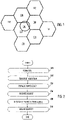
- Fig. 1 shows an example of the operation area of a network operator, where a cell 100 created by a fake base station is within the area covered by cells 102, 104, 106, 108, 110, 112, 114, 116 created by base stations of the network operator.
- the fake base station is configured to utilize the same radio technology as the cells of the network operator.
- Cellular mobile devices in the area see the cell provided by the fake base station as another one of the operator cells.
- the cell of the fake base station is not a part of the cellular operator network.
- the cells created by the real cellular base stations 102 to 116 support a given base station channel bandwidth defined by the network operator.
- the operator network provides cells 102 to 116 in the operation area with a downlink radio channel power level.
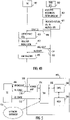
- Fig. 2 is a flowchart illustrating an embodiment. The flowchart illustrates the operation of an apparatus which may be a fake base station or a part of a fake base station.
- the apparatus is configured to form a cell 100 for carrying out downlink and uplink communication with cellular mobile devices, the cell having a physical cell identity and a tracking area code unused by neighboring real cells of a communication system.
- the communication system the neighboring real cells belong is Long term evolution LTE, Long term evolution advanced LTE-A or New radio NR communicating system.
- the proposed solution is not limited to the mentioned systems, but it may also be applied in other communication systems.
- the apparatus may be configured to scan neighboring real cells of the communication system to obtain information on the communication system and form the cell at least partly based on the obtained information.
- the obtained information comprises at least one of radio technology, frequency, bandwidth, sub carrier spacing, physical cell identifier, tracking area code, mobile country code MCC, mobile network code MNC, downlink power level.
- the apparatus uses one of a random tracking area code and a tracking area code unused in said operation area when forming the cell.
- the apparatus uses one of a random physical cell identification and a physical cell identification unused in said operation area when forming the cell.
- forming a cell comprises the activation of the transceiver of the fake base station using the radio technology, frequency, bandwidth, subcarrier spacing, MCC and MNC scanned from the cells of the network operation in the area.
- the transceiver uses the tracking area code which is either random or not used in the operator cells.
- the transceiver uses the physical cell identification which is either random or not used in this area to avoid interference with the cells of the network operator.
- the apparatus is configured to transmit channel bandwidth indication which indicates to cellular mobile devices that the formed cell utilizes bandwidth identical to the bandwidth utilized in neighboring real cells.
- the apparatus is configured to provide a downlink radio channel power level on a given continuous channel subset of the indicated channel bandwidth, the power level being higher than downlink radio channel power level utilized in real neighboring real cells.
- the higher power level is measured by the cellular mobile devices in the area. Typically, cellular mobile devices tend to make a handover to the cell which provides a higher downlink radio channel power level than the other cells in the area.
- a power amplifier of the fake base station is activated. This increases the downlink power level of the fake base station.
- the downlink radio channel power level provided to the channel subset as measured by the cellular mobile device is higher than the operator downlink power level as measured by the cellular mobile device.
- the fake base station when it is active, it starts broadcasting in the formed cell system information, SI, which includes the downlink power level and cell bandwidth indication.
- SI which includes the downlink power level and cell bandwidth indication.
- Cellular mobile devices in the area use the downlink power level information for estimating correct uplink power level for the connection request.
- Cellular mobile devices do not send connection requests to a cell if a cell uses a base station channel bandwidth not supported by the cellular mobile devices.
- the fake base station uses the power amplifier to increase the radio frequency, RF, power of the downlink channels.
- the majority of the RF power of the power amplifier may be used for amplifying the subset of the cell bandwidth used by the fake base station.
- the apparatus is configured to receive a communication request from a cellular mobile device.
- the fake base station When cellular mobile devices present in the area detect that the cell 100 of the fake base station has higher power level than the surrounding cells 102 to 116 of the network operator and the tracking area code of the fake base station is different than that of the operator cells, they may start sending a connection request to the fake base station. The higher downlink radio channel power level is attractive to the cellular mobile devices. The fake base station will then receive the connection request 206 from the cellular mobile device.
- the apparatus is configured to allocate downlink radio resources to the cellular mobile device from the given continuous channel subset of the indicated channel bandwidth.
- the fake base station may be configured to send a cellular identity request to the cellular mobile device.
- the apparatus is configured to receive a subscriber identity of the cellular mobile device sent from the cellular mobile device.
- the cellular mobile device will provide its cellular identity, such as its International Mobile Subscriber Identity IMSI, International Mobile Equipment Identity IMEI, Globally Unique Temporary Identifier GUTI or Subscription Concealed Identifier SUCI.
- the fake base station receives the cellular identity of the cellular mobile device and stores it.
- the identity of the mobile device has been collected.
- a timestamp associated to the step of receiving the subscriber identity can also be stored.
- a location of the fake base station associated to the step of receiving the identity can also be stored.
- the subscriber identity Once the subscriber identity is collected, it can be used for monitoring and analytics and/or communicated to a separate system (not shown) for further processing.
- the fake base station may maintain the connection for a while longer or simply transmit a reject and disconnect message to the cellular mobile device.
- the behavior of the cellular mobile device depends on the parameters of the reject and disconnect message, operator specific configuration on the SIM card/eSIM of the device and implementation of the cellular mobile device. For example, the cellular mobile device can try to connect to another cellular base station of the same or different cellular radio technology or try to connect to the fake base station again.
- the fake base station may be configured to return to a standby state where it is awaiting to receive connection requests from mobile devices.
- multiple cellular mobile devices can be connected to the fake base station at once.
- Fig. 3 illustrate an example of bandwidth usage.
- the figure shows the cell bandwidth of operator cells and the cell bandwidth of a fake base station.
- Cells created by base stations of the network operator utilize the maximum cell bandwidth 300 allocated to the network operator by the regulator.
- An example of such a bandwidth is 40 MHz.
- the cell created by the fake base station indicates to the cellular mobile devices that it supports the same cell bandwidth 302 as the operator cells but it is configured to allocate radio resource blocks (RB 308, RB 310, RB 312) to cellular mobile devices only from the subset 304 of the cell bandwidth.
- the subset has the bandwidth of 5 MHz.
- the fake cellular base station supports flexible base station channel bandwidth which allows to allocate resources from a continuous channel subset of the base station channel bandwidth.
- the bandwidth of the continuous channel subset is different than the bandwidths specified for radio frequency bands of the communication system.
- the fake base station may utilize a 5 MHz bandwidth in communication with the mobile devices although it is not supported by the operator cells and the mobile devices.
- Figs. 4A and 4B are signaling charts illustrating some embodiments of communication between a cellular mobile device 400 and a fake base station 402.
- Fig. 4A illustrates an embodiment when NR Standalone gNBs of a network operator use 40 MHz RF bandwidth and a fake gNB inside the operator network uses the same bandwidth but allocates radio resources only from a 5 MHz RF bandwidth.
- step 404 the fake gNB 402 (acting as a NR standalone gNB) is configured to use a modified mac layer which allocates radio resources from 5 MHz RF bandwidth.
- the fake gNB 402 is configured to use 40 MHz (or higher) RF bandwidth used in the surrounding cells of a network operator.
- the fake gNB 402 is configured to broadcast the synchronization channel 408 comprising channel bandwidth indication which indicates to cellular mobile devices that the cell utilizes bandwidth identical to the bandwidth utilized in neighboring real cells.
- step 410 the 5G NR cellular mobile device 400 in a Standalone mode searches for NR Standalone cells and detects the fake gNB by finding the synchronization channel of the gNB.
- step 412 the 5G NR cellular mobile device reads bandwidth indication from System Information Block Type 1, SIB1, from the fake gNB 402 transmission and notices that the gNB uses 40 MHz RF bandwidth.
- SIB1 System Information Block Type 1
- the 5G NR cellular mobile device 400 is compatible with the 40 MHz RF bandwidth but does not support 5 MHz bandwidth in this RF band.
- the 40 MHz indication of the fake gNB informs the cellular mobile device that it can request a connection to the gNB.
- the 5G NR cellular mobile device starts Registration Request procedure 414 with the gNB.
- the fake gNB allocates 418 radio resources (DL/UL resources) to the cellular mobile device 400 within the 5 MHz part of the 40 MHz RF bandwidth.
- the 5G NR cellular mobile device uses radio resources only inside the 5 MHz RF bandwidth.
- the cellular mobile device is configured to transmit identification to the fake gNB.
- the method described in Fig. 4A works with all 5G cellular mobile devices because the base station decides/controls which radio resources are used by each mobile device.
- Fig. 4B illustrates an embodiment when NR Standalone cells of operator network use 40 MHz RF bandwidth and a fake gNB inside the operator network use only from a 5 MHz RF bandwidth but broadcasts system information with the 40 MHz RF information. Part of the steps and signals are the same as in Fig 4A and are denoted with the same reference number.
- step 404 the fake gNB 402 (acting as a NR standalone gNB) is configured to use a modified mac layer which allocates radio resources from 5 MHz RF bandwidth.
- the fake gNB 402 is configured to use virtual 40 MHz bandwidth indication. Thus, it indicates to the cellular mobile devices that it uses the 40 MHz bandwidth, but the fake gNB supports only 5MHz subset for communication.
- the fake gNB is configured to broadcast the synchronization channel 408 comprising channel bandwidth indication which indicates to cellular mobile devices that the cell utilizes bandwidth identical to the bandwidth utilized in neighboring real cells.
- step 410 the 5G NR cellular mobile device 400 a Standalone mode searches for NR Standalone cells and detects the fake gNB by finding the synchronization channel of the gNB.
- step 412 the 5G NR cellular mobile device reads bandwidth indication from System Information Block Type 1, SIB1, from the fake gNB 402 transmission and notices that the gNB indicates that it uses 40 MHz RF bandwidth.
- SIB1 System Information Block Type 1
- the 5G NR cellular mobile device 400 is compatible with the 40 MHz RF bandwidth but does not support 5 MHz bandwidth in this RF band.
- the 40 MHz indication of the fake gNB informs the cellular mobile device that it can request a connection to the gNB.
- the 5G NR cellular mobile device starts Registration Request procedure 414 with the gNB.
- the fake gNB allocates 418 radio resources (DL/UL resources) to the cellular mobile device 400 within the 5 MHz part of the 40 MHz RF bandwidth.
- the 5G NR cellular mobile device uses radio resources only inside the 5 MHz RF bandwidth.
- the cellular mobile device is configured to transmit identification to the fake gNB.
- Fig. 4B utilizes the feature of NR specifications that allow a gNB to define location of synchronization signal (SSB) within the bandwidth defined for the gNB.
- SSB synchronization signal
- the fake gNB which indicates to the cellular mobile devices that it supports the 40 MHz band, may place the synchronization channel within the 5MHz subset that it in reality supports.
- the gNB of Fig 4A may place the synchronization channel within the 5MHz subset.
- the PA connected to the fake gNB increases the effective downlink power level of gNB compared to the case where the same PA is connected to the gNB using the full 40 MHz or 100 MHz RF bandwidth.
- Figs 4A and 4B are examples of how some example embodiments can be realized but there are also other alternatives.
- NR specifications define the concept of Bandwidth Parts.
- a fake gNB could command each cellular mobile device to use the Initial Bandwidth Part which is inside the 5 MHz subset of the 40 MHz available bandwidth.
- Fig. 5 illustrates an example of an apparatus in which some embodiments may be realized.
- the figure shows a block diagram of an apparatus which may be a fake base station or a part of a fake base station.
- the apparatus is depicted herein as an example illustrating some embodiments. It is apparent to a person skilled in the art that the apparatus may also comprise other functions and/or structures and not all described functions and structures are required. Although the apparatus has been depicted as one entity, different modules and memory may be implemented in one or more physical or logical entities.
- the apparatus comprises a controller or control circuitry 500.
- the controller is realized with a processor or other circuitry performing corresponding actions.
- the apparatus further comprises a transceiver 502 operationally connected to the controller 500, a power amplifier 504 operationally connected to the transceiver 502 and a memory or identity storage 506 operationally connected to the controller 500.
- the memory 506 may store data.
- identities of cellular mobile devices are stored in the memory.
- the memory may store software executable by the controller or processor 500.
- the memory may be integrated in the controller or processor 500.
- the transceiver 502 may be configured to scan the network 514 maintained by a network operator to obtain information about the network before the fake base station 402 is activated.
- the obtained information comprises at least one of radio technology, frequency, bandwidth, subcarrier spacing, physical cell identifier, tracking area code, mobile network code, mobile country code, downlink power level.
- the fake base station 402 may broadcast system information 508 via the power amplifier 504. It is configured to provide downlink communication 510 and receive uplink communication 512 to/from a cellular mobile device or User Equipment (UE) 400.
- the controller or processor 500 controls the network scanning and the identity collection process using the transceiver 502, the power amplifier 504 and the identity storage 506.
- the controller or processor 500 is also configured to handle cellular protocol messages used in uplink 512 and downlink 510 communications with the cellular mobile device or User Equipment 400.
- the controller 500, transceiver 502 and power amplifier 504 are configured to form a cell 100 for carrying out uplink and downlink communication with cellular mobile devices, the cell having a physical cell identity and a tracking area code unused by neighboring real cells of a communication system.
- the controller 500, transceiver 502 and power amplifier 504 are configured to transmit channel bandwidth indication which indicates to cellular mobile devices that the formed cell utilizes bandwidth identical to the bandwidth utilized in neighboring real cells.
- the controller 500, transceiver 502 and power amplifier 504 are configured to provide a downlink radio channel power level on a given continuous channel subset of the indicated channel bandwidth, the power level being higher than downlink radio channel power level utilized in real neighboring real cells.
- controller 500 and transceiver 502 are configured to receive a communication request from a cellular mobile device.
- the controller 500 is configured to allocate radio resources to the cellular mobile device from the given continuous channel subset of the indicated channel bandwidth.
- the controller 500 and transceiver 502 are configured to receive a subscriber identity of the cellular mobile device sent from the cellular mobile device.
- the subscriber identity may be stored in the memory 506.
- the apparatuses or controllers able to perform the above-described steps may be implemented as an electronic digital computer, processing system or a circuitry which may comprise a working memory (random access memory, RAM), a central processing unit (CPU), and a system clock.
- the CPU may comprise a set of registers, an arithmetic logic unit, and a controller.
- the processing system, controller or the circuitry is controlled by a sequence of program instructions transferred to the CPU from the RAM.
- the controller may contain a number of microinstructions for basic operations. The implementation of microinstructions may vary depending on the CPU design.
- the program instructions may be coded by a programming language, which may be a high-level programming language, such as C, Java, etc., or a low-level programming language, such as a machine language, or an assembler.
- the electronic digital computer may also have an operating system, which may provide system services to a computer program written with the program instructions.
- circuitry refers to all of the following: (a) hardware-only circuit implementations, such as implementations in only analog and/or digital circuitry, and (b) combinations of circuits and software (and/or firmware), such as (as applicable): (i) a combination of processor(s) or (ii) portions of processor(s)/software including digital signal processor(s), software, and memory(ies) that work together to cause an apparatus to perform various functions, and (c) circuits, such as a microprocessor(s) or a portion of a microprocessor(s), that require software or firmware for operation, even if the software or firmware is not physically present.
- circuitry' applies to all uses of this term in this application.
- the term 'circuitry' would also cover an implementation of merely a processor (or multiple processors) or a portion of a processor and its (or their) accompanying software and/or firmware.
- the term 'circuitry' would also cover, for example and if applicable to the particular element, a baseband integrated circuit or applications processor integrated circuit for a mobile phone or a similar integrated circuit in a server, a cellular network device, or another network device.
- An embodiment provides a computer program embodied on a distribution medium, comprising program instructions which, when loaded into an electronic apparatus, are configured to control the apparatus to execute the embodiments described above.
- the computer program may be in source code form, object code form, or in some intermediate form, and it may be stored in some sort of carrier, which may be any entity or device capable of carrying the program.
- carrier include a record medium, computer memory, read-only memory, and a software distribution package, for example.
- the computer program may be executed in a single electronic digital computer or it may be distributed amongst several computers.
- the apparatus may also be implemented as one or more integrated circuits, such as application-specific integrated circuits ASIC.
- Other hardware embodiments are also feasible, such as a circuit built of separate logic components.
- a hybrid of these different implementations is also feasible.
- an apparatus comprising a transceiver, a power amplifier and a processor configured to control the transceiver and the power amplifier to form a cell for carrying out uplink and downlink communication with cellular mobile devices, the cell having a physical cell identity and a tracking area code unused by neighboring real cells of a communication system, transmit channel bandwidth indication which indicates to cellular mobile devices the formed cell utilizes bandwidth identical to the bandwidth utilized in neighboring real cells, provide a downlink radio channel power level on a given continuous channel subset of the indicated channel bandwidth, the power level being higher than downlink radio channel power level utilized in real neighboring real cells, receive a communication request from a cellular mobile device, allocate radio resources to the cellular mobile device from the given continuous channel subset of the indicated channel bandwidth and receive a subscriber identity of the cellular mobile device sent from the cellular mobile device.
Description
- The invention relates generally to collecting the identity of a subscriber terminal in use and specifically to an apparatus, and a method for performing the identity collection.
- Collection of identities of cellular mobile devices is useful, when authorities need to locate a lost person who carries a cellular mobile phone or when they need to collect evidence of cellular device communication, for example. This is typically achieved using fake cellular base stations to which the cellular mobile devices connect. During connection setup, the identity of the mobile device may be detected and collected.
- There are various cellular communication systems in use in the world. Example of communication systems comprise Global system for mobile communication GSM, General Packet Radio Service GPRS, Enhanced General Packet Radio Service EGPRS, Wideband Code Division Multiple Access WCDMA, The universal mobile telecommunications system UMTS, Long term evolution LTE, Long term evolution advanced LTE-A, New radio NR or 5G, to name a few.
- As technology advances, the systems may utilize radio resources in a different manner. For example, commercial LTE networks use 1.4, 3, 5, 10 or 20 MHz radio frequency, RF, bandwidth. Typically, 20 MHz RF bandwidth is used by LTE networks to provide the highest possible speed and to provide service to a large number of LTE User Equipment, UE, at the same time. Fake cellular base stations used by authorities can use the same or smaller bandwidth than the commercial cellular network. An example of prior art solutions is disclosed in
US9167456 US 2019/246442 A1 describes a wireless device which receives a radio resource control message from a first base station. The documentEP 2733973 A2 describes a subscriber terminal identification. - Solutions working in earlier communication system do not necessarily operate optimally in new developing communication systems such as in 5G, or NR.
- The present invention seeks to provide an improved method and an improved arrangement for collecting identities of cellular mobile devices.
- According to an aspect of the present invention, there is provided an apparatus comprises means for forming a cell for carrying out uplink and downlink communication with cellular mobile devices, the cell having a physical cell identity and a tracking area code unused by neighboring real cells of a communication system; means for transmitting channel bandwidth indication which indicates to cellular mobile devices that the formed cell utilizes bandwidth identical to the bandwidth utilized in neighboring real cells; means for providing a downlink radio channel power level on a given continuous channel subset of the indicated channel bandwidth, the power level being higher than downlink radio channel power level utilized in real neighboring real cells, means for receiving a communication request from a cellular mobile device, means for allocating radio resources to the cellular mobile device from the given continuous channel subset of the indicated channel bandwidth; and means for receiving a subscriber identity of the cellular mobile device sent from the cellular mobile device.
- According to an aspect of the present invention, there is provided a method for identity collection of a cellular mobile device, the method comprising: forming a cell for carrying out uplink and downlink communication with cellular mobile devices, the cell having a physical cell identity and a tracking area code unused by neighboring real cells of a communication system; transmitting channel bandwidth indication which indicates to cellular mobile devices the formed cell utilizes bandwidth identical to the bandwidth utilized in neighboring real cells; providing a downlink radio channel power level on a given continuous channel subset of the indicated channel bandwidth, the power level being higher than downlink radio channel power level utilized in real neighboring real cells; receiving a communication request from a cellular mobile device; allocating radio resources to the cellular mobile device from the given continuous channel subset of the indicated channel bandwidth and receiving a subscriber identity of the cellular mobile device sent from the cellular mobile device.
- In an embodiment, a processor of the apparatus is configured to control a transceiver and a power amplifier of the apparatus further to support communication with cellular mobile devices on bandwidth identical to the bandwidth utilized in neighboring real cells; and allocate majority of the downlink radio channel power on the given continuous channel subset.
- In an embodiment, the transceiver and the power amplifier of the apparatus are configured to communicate with cellular mobile devices only on the given continuous channel subset and the processor of the apparatus is configured to control allocate all the downlink radio channel power on the given continuous channel subset.
- In an embodiment, the communication system the neighboring real cells belong to is Long term evolution LTE, Long term evolution advanced LTE-A or New radio NR communicating system.
- In an embodiment, the processor of the apparatus is configured to control the transceiver and the power amplifier further to transmit channel bandwidth indication within the given continuous channel subset.
- In an embodiment, the processor of the apparatus is configured to control the transceiver and the power amplifier further to scan neighboring real cells of the communication system to obtain information on the communication system, and form the cell at least partly based on the obtained information.
- In an embodiment, the obtained information comprises at least one of radio technology, frequency, bandwidth, sub carrier spacing, physical cell identifier, tracking area code, mobile network code, mobile country code, downlink power level.
- In an embodiment, the processor of the apparatus is configured to control the transceiver and the power amplifier further to form a cell using one of a random tracking area code and a tracking area code unused in said operation area.
- In an embodiment, the processor of the apparatus is configured to control the transceiver and the power amplifier further to form a cell using one of a random physical cell identification and a physical cell identification unused in said operation area.
- In an embodiment, the apparatus further comprises a memory, the processor being configured to store the received subscriber identity of the cellular mobile device into the memory.
- In an embodiment, the bandwidth of the continuous channel subset is different than the bandwidths specified for radio frequency bands of the communication system.
- The embodiments and features described in this specification that do not fall under the scope of the independent claims are to be interpreted as examples useful for understanding various embodiments of the invention.
- Example embodiments of the present invention are described below, by way of example only, with reference to the accompanying drawings, in which
-
Figure 1 illustrates an example of the operation area of a network operator; -
Figure 2 is a flowchart illustrating an embodiment; -
Figure 3 illustrates an example of bandwidth usage; -
Figures 4A and4B are signaling charts illustrating some embodiments and -
Figure 5 illustrates an example of an apparatus in which some embodiments may be realized. - The following embodiments are only examples. Although the specification may refer to "an" embodiment in several locations, this does not necessarily mean that each such reference is to the same embodiment(s), or that the feature only applies to a single embodiment. Single features of different embodiments may also be combined to provide other embodiments. Furthermore, words "comprising" and "including" should be understood as not limiting the described embodiments to consist of only those features that have been mentioned and such embodiments may contain also features/structures that have not been specifically mentioned.
- It should be noted that while Figures illustrate various embodiments of apparatuses, they are simplified block diagrams that only show some structures and functional entities. The connections shown in these Figures are logical connections; the actual physical connections may be different. Interfaces between the various elements may be implemented with suitable interface technologies, such as a message interface, a method interface, a sub-routine call interface, a block interface, or any hardware/software means enabling communication between functional sub-units. It is apparent to a person skilled in the art that the described apparatuses may also comprise other functions and structures. It should be appreciated that details of some functions, structures, and the protocols used for communication are irrelevant to the actual invention.
- Communication systems are developed in international co-operation with network manufactures, operators, and national telecommunication authorities. 5G or New Radio, or NR, is one new communication systems in development by 3GPP (3rd Generation Partnership Project (3GPP). In the first phase, 5G or NR will operate in connection with 4G communication network, but in near future also standalone 5G or NR networks will emerge on the market.
- Each cellular mobile device, user terminal (or user equipment, UE) hardware has unique identifier. The identifier may be denoted as the permanent equipment identifier, PEI, or international mobile equipment identifier, IMEI.
- A cellular mobile device wishing to utilize services of a wireless communication system such as a cellular network, needs to have a subscription from the operator of the communication system. Typically, a subscription is bounded to a physical Universal Subscriber Identity Module, USIM, card and the subscription can be identified by a unique subscription permanent identifier, SUPI, denoted also an international mobile subscriber identity, IMSI. SUPI consists of the mobile country code (MCC), mobile network code (MNC), and the mobile subscription identification number (MSIN).
- There are also so-called embedded USIMs or electronic SIMs, eSIM, available. An eSIM is a digital USIM that allows the owner to activate a subscription to a communication system without having to use a physical USIM card.
- To protect unauthorized use of IMSI, in many cellular systems an alternate value that a cellular mobile device can use instead of the IMSI (whenever possible) to access the system network is used. This alternate identification is denoted Globally Unique Temporary Identifier GUTI. Unlike an IMSI, a GUTI is not permanent and is changed into a new value whenever generated.
- In 5G systems, security specifications do not allow plain-text transmissions of SUPI over the radio interface. Instead, an encrypted identifier containing the concealed SUPI is transmitted. This concealed SUPI is known as SUCI (Subscription Concealed Identifier).
- In the development of communication systems, the trend is to increase capacity and minimize latency, for example. For this reason, the channels and bandwidths used in the new systems may be different than in the older systems. For example, in 5G the channels and bandwidth may be different compared to earlier 4G. 3GPP specifications define that 5G UEs can support RF bandwidth from 5 MHz to 100 MHz but 5 MHz RF bandwidth is not supported in all RF bands. Especially in new RF bands introduced for NR, 5 MHz RF bandwidth is not specified.
- 3GPP specification 38.104 v15.7.0, incorporated herein by reference, defines different NR channel bandwidth requirements in different RF bands. For example, in the band n77 (3300-4200 MHz), n78 (3300-3800 MHz) and n79 (4400 - 5000 MHz), the following BS (base station) channel bandwidths are possible:
Table 1 NR band / SCS / BS channel bandwidth NR Band SCS kHz 5 MHz 10 MH z 15 MH z 20 MH z 25 MH z 30 MH z 40 MH z 50 MH z 60 MH z 70 MH z 80 MH z 90 MH z 100 MH z n77 15 Yes Yes Yes Yes Yes Yes 30 Yes Yes Yes Yes Yes Yes Yes Yes Yes Yes Yes 60 Yes Yes Yes Yes Yes Yes Yes Yes Yes Yes Yes n78 15 Yes Yes Yes Yes Yes Yes 30 Yes Yes Yes Yes Yes Yes Yes Yes Yes Yes Yes 60 Yes Yes Yes Yes Yes Yes Yes Yes Yes Yes Yes n79 15 Yes Yes 30 Yes Yes Yes Yes Yes 60 Yes Yes Yes Yes Yes - Table 1 illustrates base station channel bandwidths and subcarrier spacing, SCS, per operating band in Frequency Range 1, FR1. The missing "Yes" in the 5 MHz column means that the 5 MHz RF bandwidth is not supported in the bands n77, n78 and n79. In addition, the specification 38.104 specifies that if the subcarrier spacing of a NR cell is 30 kHz or 60 kHz, the cell cannot use 5 MHz RF bandwidth.
- Using narrower bandwidths in fake cellular base stations have several advantages. A narrower bandwidth enables to build physically smaller devices which are easier to transport and also simplifies the structure of the devices. Further, as the transmission power of the power amplifier of the fake base station is directed to the continuous channel subset instead of the wider bandwidth, it is possible to obtain higher the downlink radio channel power level in the continuous channel subset than downlink radio channel power level utilized in real neighboring real cells which transmit utilizing wider bandwidth.
-
Fig. 1 shows an example of the operation area of a network operator, where acell 100 created by a fake base station is within the area covered bycells cellular base stations 102 to 116 support a given base station channel bandwidth defined by the network operator. Further, the operator network providescells 102 to 116 in the operation area with a downlink radio channel power level. -
Fig. 2 is a flowchart illustrating an embodiment. The flowchart illustrates the operation of an apparatus which may be a fake base station or a part of a fake base station. - In
step 200, the apparatus is configured to form acell 100 for carrying out downlink and uplink communication with cellular mobile devices, the cell having a physical cell identity and a tracking area code unused by neighboring real cells of a communication system. - In an embodiment, the communication system the neighboring real cells belong is Long term evolution LTE, Long term evolution advanced LTE-A or New radio NR communicating system. However, the proposed solution is not limited to the mentioned systems, but it may also be applied in other communication systems.
- In an embodiment, prior forming the cell the apparatus may be configured to scan neighboring real cells of the communication system to obtain information on the communication system and form the cell at least partly based on the obtained information.
- In an embodiment, the obtained information comprises at least one of radio technology, frequency, bandwidth, sub carrier spacing, physical cell identifier, tracking area code, mobile country code MCC, mobile network code MNC, downlink power level.
- In an embodiment, the apparatus uses one of a random tracking area code and a tracking area code unused in said operation area when forming the cell.
- In an embodiment, the apparatus uses one of a random physical cell identification and a physical cell identification unused in said operation area when forming the cell.
- Thus, in an embodiment, forming a cell comprises the activation of the transceiver of the fake base station using the radio technology, frequency, bandwidth, subcarrier spacing, MCC and MNC scanned from the cells of the network operation in the area. To make the fake base station attractive to cellular mobile devices, the transceiver uses the tracking area code which is either random or not used in the operator cells. The transceiver uses the physical cell identification which is either random or not used in this area to avoid interference with the cells of the network operator.
- In
step 202, the apparatus is configured to transmit channel bandwidth indication which indicates to cellular mobile devices that the formed cell utilizes bandwidth identical to the bandwidth utilized in neighboring real cells. - In
step 204, the apparatus is configured to provide a downlink radio channel power level on a given continuous channel subset of the indicated channel bandwidth, the power level being higher than downlink radio channel power level utilized in real neighboring real cells. The higher power level is measured by the cellular mobile devices in the area. Typically, cellular mobile devices tend to make a handover to the cell which provides a higher downlink radio channel power level than the other cells in the area. - In an embodiment, when the fake base station is active and a cell has been formed, a power amplifier of the fake base station is activated. This increases the downlink power level of the fake base station. When a cellular mobile device is in the operating range of the fake base station, the downlink radio channel power level provided to the channel subset as measured by the cellular mobile device is higher than the operator downlink power level as measured by the cellular mobile device.
- In an embodiment, when the fake base station is active, it starts broadcasting in the formed cell system information, SI, which includes the downlink power level and cell bandwidth indication. Cellular mobile devices in the area use the downlink power level information for estimating correct uplink power level for the connection request. Cellular mobile devices do not send connection requests to a cell if a cell uses a base station channel bandwidth not supported by the cellular mobile devices.
- In an embodiment, the fake base station uses the power amplifier to increase the radio frequency, RF, power of the downlink channels. The majority of the RF power of the power amplifier may be used for amplifying the subset of the cell bandwidth used by the fake base station. As a result, when a cellular mobile device is in the operating range of the fake base station, from the cellular mobile device point of view, the effective RF power of the fake base station is higher compared to the situation where the same power amplifier would be used for amplifying the full bandwidth.
- In
step 206, the apparatus is configured to receive a communication request from a cellular mobile device. - When cellular mobile devices present in the area detect that the
cell 100 of the fake base station has higher power level than the surroundingcells 102 to 116 of the network operator and the tracking area code of the fake base station is different than that of the operator cells, they may start sending a connection request to the fake base station. The higher downlink radio channel power level is attractive to the cellular mobile devices. The fake base station will then receive theconnection request 206 from the cellular mobile device. - In
step 208, the apparatus is configured to allocate downlink radio resources to the cellular mobile device from the given continuous channel subset of the indicated channel bandwidth. - Using the radio resources, the fake base station may be configured to send a cellular identity request to the cellular mobile device.
- In
step 210, the apparatus is configured to receive a subscriber identity of the cellular mobile device sent from the cellular mobile device. - As the request transmitted by the fake base station is normal behavior for any base station, real or fake, the cellular mobile device will provide its cellular identity, such as its International Mobile Subscriber Identity IMSI, International Mobile Equipment Identity IMEI, Globally Unique Temporary Identifier GUTI or Subscription Concealed Identifier SUCI. The fake base station receives the cellular identity of the cellular mobile device and stores it. The identity of the mobile device has been collected. In an embodiment, as part of the storing of the identity, a timestamp associated to the step of receiving the subscriber identity can also be stored. Additionally, a location of the fake base station associated to the step of receiving the identity can also be stored.
- Once the subscriber identity is collected, it can be used for monitoring and analytics and/or communicated to a separate system (not shown) for further processing.
- Further, once the subscriber identity is collected, the fake base station may maintain the connection for a while longer or simply transmit a reject and disconnect message to the cellular mobile device. Having received a reject message, the behavior of the cellular mobile device depends on the parameters of the reject and disconnect message, operator specific configuration on the SIM card/eSIM of the device and implementation of the cellular mobile device. For example, the cellular mobile device can try to connect to another cellular base station of the same or different cellular radio technology or try to connect to the fake base station again.
- In an embodiment, the fake base station may be configured to return to a standby state where it is awaiting to receive connection requests from mobile devices. As will be readily understood, multiple cellular mobile devices can be connected to the fake base station at once.
-
Fig. 3 illustrate an example of bandwidth usage. The figure shows the cell bandwidth of operator cells and the cell bandwidth of a fake base station. Cells created by base stations of the network operator utilize themaximum cell bandwidth 300 allocated to the network operator by the regulator. An example of such a bandwidth is 40 MHz. The cell created by the fake base station indicates to the cellular mobile devices that it supports thesame cell bandwidth 302 as the operator cells but it is configured to allocate radio resource blocks (RB 308,RB 310, RB 312) to cellular mobile devices only from thesubset 304 of the cell bandwidth. In an embodiment the subset has the bandwidth of 5 MHz. The fake cellular base station supports flexible base station channel bandwidth which allows to allocate resources from a continuous channel subset of the base station channel bandwidth. - Thus in an embodiment, the bandwidth of the continuous channel subset is different than the bandwidths specified for radio frequency bands of the communication system. For example, the fake base station may utilize a 5 MHz bandwidth in communication with the mobile devices although it is not supported by the operator cells and the mobile devices.
-
Figs. 4A and4B are signaling charts illustrating some embodiments of communication between a cellularmobile device 400 and afake base station 402. - The example of
Fig. 4A illustrates an embodiment when NR Standalone gNBs of a network operator use 40 MHz RF bandwidth and a fake gNB inside the operator network uses the same bandwidth but allocates radio resources only from a 5 MHz RF bandwidth. - In
step 404 the fake gNB 402 (acting as a NR standalone gNB) is configured to use a modified mac layer which allocates radio resources from 5 MHz RF bandwidth. - In
step 406 thefake gNB 402 is configured to use 40 MHz (or higher) RF bandwidth used in the surrounding cells of a network operator. - Next the
fake gNB 402 is configured to broadcast thesynchronization channel 408 comprising channel bandwidth indication which indicates to cellular mobile devices that the cell utilizes bandwidth identical to the bandwidth utilized in neighboring real cells. - In
step 410 the 5G NR cellularmobile device 400 in a Standalone mode searches for NR Standalone cells and detects the fake gNB by finding the synchronization channel of the gNB. - In
step 412 the 5G NR cellular mobile device reads bandwidth indication from System Information Block Type 1, SIB1, from thefake gNB 402 transmission and notices that the gNB uses 40 MHz RF bandwidth. - The 5G NR cellular
mobile device 400 is compatible with the 40 MHz RF bandwidth but does not support 5 MHz bandwidth in this RF band. The 40 MHz indication of the fake gNB informs the cellular mobile device that it can request a connection to the gNB. - The 5G NR cellular mobile device starts
Registration Request procedure 414 with the gNB. - The fake gNB allocates 418 radio resources (DL/UL resources) to the cellular
mobile device 400 within the 5 MHz part of the 40 MHz RF bandwidth. - In
step 420 the 5G NR cellular mobile device uses radio resources only inside the 5 MHz RF bandwidth. The cellular mobile device is configured to transmit identification to the fake gNB. - The method described in
Fig. 4A works with all 5G cellular mobile devices because the base station decides/controls which radio resources are used by each mobile device. - The example of
Fig. 4B illustrates an embodiment when NR Standalone cells of operator network use 40 MHz RF bandwidth and a fake gNB inside the operator network use only from a 5 MHz RF bandwidth but broadcasts system information with the 40 MHz RF information. Part of the steps and signals are the same as inFig 4A and are denoted with the same reference number. - In
step 404 the fake gNB 402 (acting as a NR standalone gNB) is configured to use a modified mac layer which allocates radio resources from 5 MHz RF bandwidth. - In
step 422 thefake gNB 402 is configured to use virtual 40 MHz bandwidth indication. Thus, it indicates to the cellular mobile devices that it uses the 40 MHz bandwidth, but the fake gNB supports only 5MHz subset for communication. - Next the fake gNB is configured to broadcast the
synchronization channel 408 comprising channel bandwidth indication which indicates to cellular mobile devices that the cell utilizes bandwidth identical to the bandwidth utilized in neighboring real cells. - In
step 410 the 5G NR cellular mobile device 400 a Standalone mode searches for NR Standalone cells and detects the fake gNB by finding the synchronization channel of the gNB. - In
step 412 the 5G NR cellular mobile device reads bandwidth indication from System Information Block Type 1, SIB1, from thefake gNB 402 transmission and notices that the gNB indicates that it uses 40 MHz RF bandwidth. - The 5G NR cellular
mobile device 400 is compatible with the 40 MHz RF bandwidth but does not support 5 MHz bandwidth in this RF band. The 40 MHz indication of the fake gNB informs the cellular mobile device that it can request a connection to the gNB. - The 5G NR cellular mobile device starts
Registration Request procedure 414 with the gNB. - The fake gNB allocates 418 radio resources (DL/UL resources) to the cellular
mobile device 400 within the 5 MHz part of the 40 MHz RF bandwidth. - In
step 420 the 5G NR cellular mobile device uses radio resources only inside the 5 MHz RF bandwidth. The cellular mobile device is configured to transmit identification to the fake gNB. - The example of
Fig. 4B utilizes the feature of NR specifications that allow a gNB to define location of synchronization signal (SSB) within the bandwidth defined for the gNB. Thus, the fake gNB, which indicates to the cellular mobile devices that it supports the 40 MHz band, may place the synchronization channel within the 5MHz subset that it in reality supports. - The same applies for the gNB of
Fig 4A as well. Although it supports the whole 40MHz band, it may place the synchronization channel within the 5MHz subset. - When these methods are used, the PA connected to the fake gNB increases the effective downlink power level of gNB compared to the case where the same PA is connected to the gNB using the full 40 MHz or 100 MHz RF bandwidth.
- The above examples of
Figs 4A and4B are examples of how some example embodiments can be realized but there are also other alternatives. For example, NR specifications define the concept of Bandwidth Parts. A fake gNB could command each cellular mobile device to use the Initial Bandwidth Part which is inside the 5 MHz subset of the 40 MHz available bandwidth. -
Fig. 5 illustrates an example of an apparatus in which some embodiments may be realized. The figure shows a block diagram of an apparatus which may be a fake base station or a part of a fake base station. - It should be understood that the apparatus is depicted herein as an example illustrating some embodiments. It is apparent to a person skilled in the art that the apparatus may also comprise other functions and/or structures and not all described functions and structures are required. Although the apparatus has been depicted as one entity, different modules and memory may be implemented in one or more physical or logical entities.
- The apparatus comprises a controller or
control circuitry 500. In an embodiment, the controller is realized with a processor or other circuitry performing corresponding actions. The apparatus further comprises atransceiver 502 operationally connected to thecontroller 500, apower amplifier 504 operationally connected to thetransceiver 502 and a memory oridentity storage 506 operationally connected to thecontroller 500. - The
memory 506 may store data. In an embodiment, identities of cellular mobile devices are stored in the memory. Furthermore, the memory may store software executable by the controller orprocessor 500. The memory may be integrated in the controller orprocessor 500. - The
transceiver 502 may be configured to scan thenetwork 514 maintained by a network operator to obtain information about the network before thefake base station 402 is activated. In an embodiment, the obtained information comprises at least one of radio technology, frequency, bandwidth, subcarrier spacing, physical cell identifier, tracking area code, mobile network code, mobile country code, downlink power level. Once activated, thefake base station 402 may broadcastsystem information 508 via thepower amplifier 504. It is configured to providedownlink communication 510 and receiveuplink communication 512 to/from a cellular mobile device or User Equipment (UE) 400. The controller orprocessor 500 controls the network scanning and the identity collection process using thetransceiver 502, thepower amplifier 504 and theidentity storage 506. The controller orprocessor 500 is also configured to handle cellular protocol messages used inuplink 512 anddownlink 510 communications with the cellular mobile device orUser Equipment 400. - In an embodiment, the
controller 500,transceiver 502 andpower amplifier 504 are configured to form acell 100 for carrying out uplink and downlink communication with cellular mobile devices, the cell having a physical cell identity and a tracking area code unused by neighboring real cells of a communication system. - In an embodiment, the
controller 500,transceiver 502 andpower amplifier 504 are configured to transmit channel bandwidth indication which indicates to cellular mobile devices that the formed cell utilizes bandwidth identical to the bandwidth utilized in neighboring real cells. - In an embodiment, the
controller 500,transceiver 502 andpower amplifier 504 are configured to provide a downlink radio channel power level on a given continuous channel subset of the indicated channel bandwidth, the power level being higher than downlink radio channel power level utilized in real neighboring real cells. - In an embodiment, the
controller 500 andtransceiver 502 are configured to receive a communication request from a cellular mobile device. - In an embodiment, the
controller 500 is configured to allocate radio resources to the cellular mobile device from the given continuous channel subset of the indicated channel bandwidth. - In an embodiment, the
controller 500 andtransceiver 502 are configured to receive a subscriber identity of the cellular mobile device sent from the cellular mobile device. The subscriber identity may be stored in thememory 506. - The steps and related functions described in the above and attached figures are in no absolute chronological order, and some of the steps may be performed simultaneously or in an order differing from the given one. Other functions can also be executed between the steps or within the steps. Some of the steps can also be left out or replaced with a corresponding step.
- The apparatuses or controllers able to perform the above-described steps may be implemented as an electronic digital computer, processing system or a circuitry which may comprise a working memory (random access memory, RAM), a central processing unit (CPU), and a system clock. The CPU may comprise a set of registers, an arithmetic logic unit, and a controller. The processing system, controller or the circuitry is controlled by a sequence of program instructions transferred to the CPU from the RAM. The controller may contain a number of microinstructions for basic operations. The implementation of microinstructions may vary depending on the CPU design. The program instructions may be coded by a programming language, which may be a high-level programming language, such as C, Java, etc., or a low-level programming language, such as a machine language, or an assembler. The electronic digital computer may also have an operating system, which may provide system services to a computer program written with the program instructions.
- As used in this application, the term 'circuitry' refers to all of the following: (a) hardware-only circuit implementations, such as implementations in only analog and/or digital circuitry, and (b) combinations of circuits and software (and/or firmware), such as (as applicable): (i) a combination of processor(s) or (ii) portions of processor(s)/software including digital signal processor(s), software, and memory(ies) that work together to cause an apparatus to perform various functions, and (c) circuits, such as a microprocessor(s) or a portion of a microprocessor(s), that require software or firmware for operation, even if the software or firmware is not physically present.
- This definition of 'circuitry' applies to all uses of this term in this application. As a further example, as used in this application, the term 'circuitry' would also cover an implementation of merely a processor (or multiple processors) or a portion of a processor and its (or their) accompanying software and/or firmware. The term 'circuitry' would also cover, for example and if applicable to the particular element, a baseband integrated circuit or applications processor integrated circuit for a mobile phone or a similar integrated circuit in a server, a cellular network device, or another network device.
- An embodiment provides a computer program embodied on a distribution medium, comprising program instructions which, when loaded into an electronic apparatus, are configured to control the apparatus to execute the embodiments described above.
- The computer program may be in source code form, object code form, or in some intermediate form, and it may be stored in some sort of carrier, which may be any entity or device capable of carrying the program. Such carriers include a record medium, computer memory, read-only memory, and a software distribution package, for example. Depending on the processing power needed, the computer program may be executed in a single electronic digital computer or it may be distributed amongst several computers.
- The apparatus may also be implemented as one or more integrated circuits, such as application-specific integrated circuits ASIC. Other hardware embodiments are also feasible, such as a circuit built of separate logic components. A hybrid of these different implementations is also feasible. When selecting the method of implementation, a person skilled in the art will consider the requirements set for the size and power consumption of the apparatus, the necessary processing capacity, production costs, and production volumes, for example.
- While illustrated in the block diagrams as groups of discrete components communicating with each other via distinct data signal connections, it will be understood by those skilled in the art that the illustrated embodiments may be provided by a combination of hardware and software components, with some components being implemented by a given function or operation of a hardware or software system, and many of the data paths illustrated being implemented by data communication within a computer application or operating system. The structure illustrated is thus provided for efficiency of teaching the described embodiments.
- In an embodiment, there is provided an apparatus comprising a transceiver, a power amplifier and a processor configured to control the transceiver and the power amplifier to form a cell for carrying out uplink and downlink communication with cellular mobile devices, the cell having a physical cell identity and a tracking area code unused by neighboring real cells of a communication system, transmit channel bandwidth indication which indicates to cellular mobile devices the formed cell utilizes bandwidth identical to the bandwidth utilized in neighboring real cells, provide a downlink radio channel power level on a given continuous channel subset of the indicated channel bandwidth, the power level being higher than downlink radio channel power level utilized in real neighboring real cells, receive a communication request from a cellular mobile device, allocate radio resources to the cellular mobile device from the given continuous channel subset of the indicated channel bandwidth and receive a subscriber identity of the cellular mobile device sent from the cellular mobile device.
- It will be obvious to a person skilled in the art that, as the technology advances, the inventive concept can be implemented in various ways. The invention and its embodiments are not limited to the examples described above but may vary within the scope of the claims.
Claims (16)
- An apparatus comprisingmeans (500, 502, 506) for forming a cell for carrying out uplink and downlink communication with cellular mobile devices, the cell having a physical cell identity and a tracking area code unused by neighboring real cells of a communication system;means (500, 502, 506) for transmitting channel bandwidth indication which indicates to cellular mobile devices that the formed cell utilizes bandwidth identical to the bandwidth utilized in neighboring real cells;means (500, 502, 506) for providing a downlink radio channel power level on a given continuous channel subset of the indicated channel bandwidth, the downlink radio channel power level being higher than downlink radio channel power level utilized in real neighboring real cells;means (500, 502, 506) for receiving a communication request from a cellular mobile device;means (500, 502, 506) for allocating radio resources to the cellular mobile device from the given continuous channel subset of the indicated channel bandwidth; andmeans (500, 502, 506) for receiving a subscriber identity of the cellular mobile device sent from the cellular mobile device.
- The apparatus of claim 1, further comprisingmeans for supporting communication with cellular mobile devices on bandwidth identical to the bandwidth utilized in neighboring real cells; andmeans for allocating majority of the downlink radio channel power on the given continuous channel subset.
- The apparatus of claim 1, further comprisingmeans for communicating with cellular mobile devices only on the given continuous channel subset andmeans for allocating all the downlink radio channel power on the given continuous channel subset.
- The apparatus of claim 1, wherein communication system the neighboring real cells belong is Long term evolution LTE, Long term evolution advanced LTE-A or New radio NR communicating system.
- The apparatus of claim 1, further comprising means for controlling the transceiver and the power amplifier further to transmit channel bandwidth indication within the given continuous channel subset.
- The apparatus of claim 1, further comprisingmeans for scanning neighboring real cells of the communication system to obtain information on the communication system;means for forming the cell at least partly based on the obtained information.
- The apparatus of claim 6, wherein the obtained information comprises at least one of radio technology, frequency, bandwidth, subcarrier spacing, physical cell identifier, tracking area code, mobile network code, mobile country code, downlink power level.
- The apparatus of claim 1, further comprising means for forming a cell using one of a random tracking area code and a tracking area code unused in said operation area and using one of a random physical cell identification and a physical cell identification unused in said operation area.
- The apparatus of claim 1, wherein the bandwidth of the continuous channel subset is different than the bandwidths specified for radio frequency bands of the communication system.
- A method for identity collection of a cellular mobile device, the method comprising:forming (200) a cell for carrying out uplink and downlink communication with cellular mobile devices, the cell having a physical cell identity and a tracking area code unused by neighboring real cells of a communication system;transmitting (202) channel bandwidth indication which indicates to cellular mobile devices the formed cell utilizes bandwidth identical to the bandwidth utilized in neighboring real cells;providing (204) a downlink radio channel power level on a given continuous channel subset of the indicated channel bandwidth, the power level being higher than downlink radio channel power level utilized in real neighboring real cells;receiving (206) a communication request from a cellular mobile device;allocating (208) radio resources to the cellular mobile device from the given continuous channel subset of the indicated channel bandwidth; andreceiving (210) a subscriber identity of the cellular mobile device sent from the cellular mobile device.
- The method of claim 10, further comprising:supporting communication with cellular mobile devices on bandwidth identical to the bandwidth utilized in neighboring real cells; andallocating majority of the downlink radio channel power on the given continuous channel subset.
- The method of claim 10, further comprising:communicating with cellular mobile devices only on the given continuous channel subset andallocating all the downlink radio channel power on the given continuous channel subset.
- The method of claim 10, wherein the bandwidth of the continuous channel subset is different than the bandwidths specified for radio frequency bands of the communication system.
- The method of claim 10, further comprising:scanning neighboring real cells of the communication system to obtain information on the communication system;forming the cell at least partly based on the obtained information.
- The method of claim 14, wherein the obtained information comprises at least one of radio technology, frequency, bandwidth, subcarrier spacing, physical cell identifier, tracking area code, mobile network code, mobile country code, downlink power level.
- A computer readable medium comprising program instructions for causing an apparatus to perform at least the following:forming (200) a cell for carrying out uplink and downlink communication with cellular mobile devices, the cell having a physical cell identity and a tracking area code unused by neighboring real cells of a communication system;transmitting (202) channel bandwidth indication which indicates to cellular mobile devices the formed cell utilizes bandwidth identical to the bandwidth utilized in neighboring real cells;providing (204) a downlink radio channel power level on a given continuous channel subset of the indicated channel bandwidth, the power level being higher than downlink radio channel power level utilized in real neighboring real cells;receiving (206) a communication request from a cellular mobile device;allocating (208) radio resources to the cellular mobile device from the given continuous channel subset of the indicated channel bandwidth; andreceiving (210) a subscriber identity of the cellular mobile device sent from the cellular mobile device.
Applications Claiming Priority (2)
| Application Number | Priority Date | Filing Date | Title |
|---|---|---|---|
| US202062976416P | 2020-02-14 | 2020-02-14 | |
| US16/946,102 US11240808B2 (en) | 2020-02-14 | 2020-06-05 | Method and arrangement for identity collection |
Publications (2)
| Publication Number | Publication Date |
|---|---|
| EP3866544A1 EP3866544A1 (en) | 2021-08-18 |
| EP3866544B1 true EP3866544B1 (en) | 2022-04-06 |
Family
ID=74561728
Family Applications (1)
| Application Number | Title | Priority Date | Filing Date |
|---|---|---|---|
| EP21155699.8A Active EP3866544B1 (en) | 2020-02-14 | 2021-02-08 | Method and arrangement for identity collection |
Country Status (6)
| Country | Link |
|---|---|
| US (1) | US11240808B2 (en) |
| EP (1) | EP3866544B1 (en) |
| CA (1) | CA3108647A1 (en) |
| DK (1) | DK3866544T3 (en) |
| ES (1) | ES2915687T3 (en) |
| PL (1) | PL3866544T3 (en) |
Cited By (1)
| Publication number | Priority date | Publication date | Assignee | Title |
|---|---|---|---|---|
| EP4297460A1 (en) * | 2022-06-23 | 2023-12-27 | EXFO Oy | Method and apparatus for identity collection |
Family Cites Families (21)
| Publication number | Priority date | Publication date | Assignee | Title |
|---|---|---|---|---|
| WO2009075620A1 (en) | 2007-12-12 | 2009-06-18 | Telefonaktiebolaget Lm Ericsson (Publ) | A method of detecting incorrect cell identity in wireless communication systems |
| TWI455626B (en) | 2009-06-22 | 2014-10-01 | Htc Corp | Method of handling positioning measurement |
| US10447441B2 (en) * | 2009-10-29 | 2019-10-15 | Nec Corporation | Wireless communication system, wireless communication method, radio station and program |
| WO2013002695A1 (en) * | 2011-06-30 | 2013-01-03 | Telefonaktiebolaget L M Ericsson (Publ) | Handover in relation to cell identity ambiguity |
| KR101833097B1 (en) | 2011-09-19 | 2018-02-27 | 엘지전자 주식회사 | Method and apparatus for measuring a position in a wireless access system |
| CN103686858B (en) | 2012-08-31 | 2018-02-06 | 华为技术有限公司 | Feedback method, base station and the user equipment of ascending control information |
| US9781137B2 (en) | 2012-10-11 | 2017-10-03 | Nokia Solutions And Networks Oy | Fake base station detection with core network support |
| FI125641B (en) | 2012-11-14 | 2015-12-31 | Exfo Oy | Subscriber terminal identification |
| US9876655B2 (en) | 2013-08-16 | 2018-01-23 | Mediatek Singapore Pte. Ltd. | Precoding-codebook-based secure uplink in LTE |
| US9955506B2 (en) | 2014-03-21 | 2018-04-24 | Telefonaktiebolaget L M Ericsson (Publ) | Adapting carrier aggregation configurations for user equipment |
| US9949125B2 (en) | 2014-08-04 | 2018-04-17 | Lg Electronics Inc. | Method for authenticating terminal in wireless communication system, and device for same |
| US9867039B2 (en) | 2015-06-26 | 2018-01-09 | Futurewei Technologies, Inc. | System and method for faked base station detection |
| US9794804B2 (en) * | 2015-09-16 | 2017-10-17 | Alcatel-Lucent Usa Inc. | Carrier priority based automatic neighboring relation optimization |
| US10873464B2 (en) | 2016-03-10 | 2020-12-22 | Futurewei Technologies, Inc. | Authentication mechanism for 5G technologies |
| US10200862B2 (en) | 2016-10-28 | 2019-02-05 | Nokia Of America Corporation | Verification of cell authenticity in a wireless network through traffic monitoring |
| US20190349765A1 (en) | 2017-01-30 | 2019-11-14 | Intel IP Corporation | Fake gnb/enb detection using identity-based authentication and encryption |
| CN117202199A (en) | 2017-06-16 | 2023-12-08 | 摩托罗拉移动有限责任公司 | Reporting monitored parameter information |
| US20190132740A1 (en) | 2017-10-31 | 2019-05-02 | Qualcomm Incorporated | Enhanced cloud information system with prefetching and caching decisions to facilitate detection of false network access nodes |
| US10750562B2 (en) | 2018-02-02 | 2020-08-18 | Ofinno, Llc | Connection failure report considering bandwidth |
| US11589228B2 (en) | 2018-05-11 | 2023-02-21 | Apple Inc. | Subscriber identity privacy protection against fake base stations |
| WO2020106546A1 (en) * | 2018-11-20 | 2020-05-28 | Intel Corporation | Mobile cellular networks authenticated access |
-
2020
- 2020-06-05 US US16/946,102 patent/US11240808B2/en active Active
-
2021
- 2021-02-08 ES ES21155699T patent/ES2915687T3/en active Active
- 2021-02-08 DK DK21155699.8T patent/DK3866544T3/en active
- 2021-02-08 EP EP21155699.8A patent/EP3866544B1/en active Active
- 2021-02-08 PL PL21155699.8T patent/PL3866544T3/en unknown
- 2021-02-11 CA CA3108647A patent/CA3108647A1/en active Pending
Cited By (1)
| Publication number | Priority date | Publication date | Assignee | Title |
|---|---|---|---|---|
| EP4297460A1 (en) * | 2022-06-23 | 2023-12-27 | EXFO Oy | Method and apparatus for identity collection |
Also Published As
| Publication number | Publication date |
|---|---|
| EP3866544A1 (en) | 2021-08-18 |
| ES2915687T3 (en) | 2022-06-24 |
| DK3866544T3 (en) | 2022-06-27 |
| CA3108647A1 (en) | 2021-08-14 |
| PL3866544T3 (en) | 2022-07-25 |
| US20210258956A1 (en) | 2021-08-19 |
| US11240808B2 (en) | 2022-02-01 |
Similar Documents
| Publication | Publication Date | Title |
|---|---|---|
| EP3908020B1 (en) | Method and apparatus for selecting an access and mobility management function in a mobile communication system | |
| EP1494497B1 (en) | A method of applying hashing algorithms in a wireless communication system | |
| US20130109301A1 (en) | D2D Discovery Process | |
| CN104662967A (en) | Apparatus and method for limiting searches for a home PLMN according to its proximity | |
| EP3507914B1 (en) | Methods for signaling or receiving cell identity, network identity, and frequency hopping patterns | |
| KR102484905B1 (en) | Paging method, terminal device and network device | |
| US20220124815A1 (en) | Method and device for transmitting user data through two-stage random access process in mobile communication system | |
| US20220330194A1 (en) | Method and apparatus for indicating mt-service for multi-sim ue | |
| EP3866544B1 (en) | Method and arrangement for identity collection | |
| CN113225696B (en) | Paging processing method, device, equipment and storage medium | |
| US20230199479A1 (en) | Capability coordination between wireless devices | |
| US20210385663A1 (en) | Utilizing nr guard band for efficient deployment of lte-m in coexistence with nr | |
| WO2008041816A1 (en) | System and method for reducing size of initial uplink message in mobile communication system | |
| EP4125298A1 (en) | Musim imsi offset value handling for paging timing collision control | |
| US20220295565A1 (en) | Enhancements for New Radio Devices with a Reduced Number of Antenna Branches | |
| WO2021186934A1 (en) | Systems and methods for supporting multi-usim user equipment | |
| CN112469107B (en) | Communication method and device | |
| EP3222106B1 (en) | Method and apparatus for efficient transmission from a dormant state | |
| US20230070472A1 (en) | System and method for multi-sim | |
| US20220303789A1 (en) | High Frequency Beam Switching | |
| US20240040364A1 (en) | Method for multi-card terminal device cooperative communication and electronic device | |
| KR20220123979A (en) | Method and apparatus for providing integrated paging in communication system | |
| CN116325937A (en) | Wireless communication method, terminal equipment and network equipment | |
| CN116368865A (en) | Wireless communication method, terminal equipment and network equipment | |
| CN116349325A (en) | Paging method and network node |
Legal Events
| Date | Code | Title | Description |
|---|---|---|---|
| PUAI | Public reference made under article 153(3) epc to a published international application that has entered the european phase |
Free format text: ORIGINAL CODE: 0009012 |
|
| STAA | Information on the status of an ep patent application or granted ep patent |
Free format text: STATUS: THE APPLICATION HAS BEEN PUBLISHED |
|
| AK | Designated contracting states |
Kind code of ref document: A1 Designated state(s): AL AT BE BG CH CY CZ DE DK EE ES FI FR GB GR HR HU IE IS IT LI LT LU LV MC MK MT NL NO PL PT RO RS SE SI SK SM TR |
|
| STAA | Information on the status of an ep patent application or granted ep patent |
Free format text: STATUS: REQUEST FOR EXAMINATION WAS MADE |
|
| 17P | Request for examination filed |
Effective date: 20210826 |
|
| RBV | Designated contracting states (corrected) |
Designated state(s): AL AT BE BG CH CY CZ DE DK EE ES FI FR GB GR HR HU IE IS IT LI LT LU LV MC MK MT NL NO PL PT RO RS SE SI SK SM TR |
|
| REG | Reference to a national code |
Ref country code: DE Ref legal event code: R079 Ref document number: 602021000036 Country of ref document: DE Free format text: PREVIOUS MAIN CLASS: H04W0072040000 Ipc: H04W0012690000 |
|
| GRAP | Despatch of communication of intention to grant a patent |
Free format text: ORIGINAL CODE: EPIDOSNIGR1 |
|
| STAA | Information on the status of an ep patent application or granted ep patent |
Free format text: STATUS: GRANT OF PATENT IS INTENDED |
|
| RIC1 | Information provided on ipc code assigned before grant |
Ipc: H04W 84/04 20090101ALN20211208BHEP Ipc: H04W 72/08 20090101ALN20211208BHEP Ipc: H04W 72/04 20090101ALI20211208BHEP Ipc: H04W 52/34 20090101ALI20211208BHEP Ipc: H04W 52/14 20090101ALI20211208BHEP Ipc: H04W 16/16 20090101ALI20211208BHEP Ipc: H04W 12/69 20210101AFI20211208BHEP |
|
| INTG | Intention to grant announced |
Effective date: 20211223 |
|
| GRAS | Grant fee paid |
Free format text: ORIGINAL CODE: EPIDOSNIGR3 |
|
| GRAA | (expected) grant |
Free format text: ORIGINAL CODE: 0009210 |
|
| STAA | Information on the status of an ep patent application or granted ep patent |
Free format text: STATUS: THE PATENT HAS BEEN GRANTED |
|
| AK | Designated contracting states |
Kind code of ref document: B1 Designated state(s): AL AT BE BG CH CY CZ DE DK EE ES FI FR GB GR HR HU IE IS IT LI LT LU LV MC MK MT NL NO PL PT RO RS SE SI SK SM TR |
|
| REG | Reference to a national code |
Ref country code: GB Ref legal event code: FG4D |
|
| REG | Reference to a national code |
Ref country code: CH Ref legal event code: EP |
|
| REG | Reference to a national code |
Ref country code: AT Ref legal event code: REF Ref document number: 1482543 Country of ref document: AT Kind code of ref document: T Effective date: 20220415 |
|
| REG | Reference to a national code |
Ref country code: IE Ref legal event code: FG4D |
|
| REG | Reference to a national code |
Ref country code: DE Ref legal event code: R096 Ref document number: 602021000036 Country of ref document: DE |
|
| REG | Reference to a national code |
Ref country code: NL Ref legal event code: FP |
|
| REG | Reference to a national code |
Ref country code: ES Ref legal event code: FG2A Ref document number: 2915687 Country of ref document: ES Kind code of ref document: T3 Effective date: 20220624 |
|
| REG | Reference to a national code |
Ref country code: DK Ref legal event code: T3 Effective date: 20220624 |
|
| REG | Reference to a national code |
Ref country code: FI Ref legal event code: FGE |
|
| REG | Reference to a national code |
Ref country code: SE Ref legal event code: TRGR |
|
| REG | Reference to a national code |
Ref country code: LT Ref legal event code: MG9D |
|
| REG | Reference to a national code |
Ref country code: GR Ref legal event code: EP Ref document number: 20220401379 Country of ref document: GR Effective date: 20220808 |
|
| REG | Reference to a national code |
Ref country code: AT Ref legal event code: MK05 Ref document number: 1482543 Country of ref document: AT Kind code of ref document: T Effective date: 20220406 |
|
| PG25 | Lapsed in a contracting state [announced via postgrant information from national office to epo] |
Ref country code: PT Free format text: LAPSE BECAUSE OF FAILURE TO SUBMIT A TRANSLATION OF THE DESCRIPTION OR TO PAY THE FEE WITHIN THE PRESCRIBED TIME-LIMIT Effective date: 20220808 Ref country code: NO Free format text: LAPSE BECAUSE OF FAILURE TO SUBMIT A TRANSLATION OF THE DESCRIPTION OR TO PAY THE FEE WITHIN THE PRESCRIBED TIME-LIMIT Effective date: 20220706 Ref country code: LT Free format text: LAPSE BECAUSE OF FAILURE TO SUBMIT A TRANSLATION OF THE DESCRIPTION OR TO PAY THE FEE WITHIN THE PRESCRIBED TIME-LIMIT Effective date: 20220406 Ref country code: HR Free format text: LAPSE BECAUSE OF FAILURE TO SUBMIT A TRANSLATION OF THE DESCRIPTION OR TO PAY THE FEE WITHIN THE PRESCRIBED TIME-LIMIT Effective date: 20220406 Ref country code: BG Free format text: LAPSE BECAUSE OF FAILURE TO SUBMIT A TRANSLATION OF THE DESCRIPTION OR TO PAY THE FEE WITHIN THE PRESCRIBED TIME-LIMIT Effective date: 20220706 Ref country code: AT Free format text: LAPSE BECAUSE OF FAILURE TO SUBMIT A TRANSLATION OF THE DESCRIPTION OR TO PAY THE FEE WITHIN THE PRESCRIBED TIME-LIMIT Effective date: 20220406 |
|
| PG25 | Lapsed in a contracting state [announced via postgrant information from national office to epo] |
Ref country code: RS Free format text: LAPSE BECAUSE OF FAILURE TO SUBMIT A TRANSLATION OF THE DESCRIPTION OR TO PAY THE FEE WITHIN THE PRESCRIBED TIME-LIMIT Effective date: 20220406 Ref country code: LV Free format text: LAPSE BECAUSE OF FAILURE TO SUBMIT A TRANSLATION OF THE DESCRIPTION OR TO PAY THE FEE WITHIN THE PRESCRIBED TIME-LIMIT Effective date: 20220406 Ref country code: IS Free format text: LAPSE BECAUSE OF FAILURE TO SUBMIT A TRANSLATION OF THE DESCRIPTION OR TO PAY THE FEE WITHIN THE PRESCRIBED TIME-LIMIT Effective date: 20220806 |
|
| REG | Reference to a national code |
Ref country code: DE Ref legal event code: R097 Ref document number: 602021000036 Country of ref document: DE |
|
| PG25 | Lapsed in a contracting state [announced via postgrant information from national office to epo] |
Ref country code: SM Free format text: LAPSE BECAUSE OF FAILURE TO SUBMIT A TRANSLATION OF THE DESCRIPTION OR TO PAY THE FEE WITHIN THE PRESCRIBED TIME-LIMIT Effective date: 20220406 Ref country code: SK Free format text: LAPSE BECAUSE OF FAILURE TO SUBMIT A TRANSLATION OF THE DESCRIPTION OR TO PAY THE FEE WITHIN THE PRESCRIBED TIME-LIMIT Effective date: 20220406 Ref country code: RO Free format text: LAPSE BECAUSE OF FAILURE TO SUBMIT A TRANSLATION OF THE DESCRIPTION OR TO PAY THE FEE WITHIN THE PRESCRIBED TIME-LIMIT Effective date: 20220406 Ref country code: EE Free format text: LAPSE BECAUSE OF FAILURE TO SUBMIT A TRANSLATION OF THE DESCRIPTION OR TO PAY THE FEE WITHIN THE PRESCRIBED TIME-LIMIT Effective date: 20220406 |
|
| PLBE | No opposition filed within time limit |
Free format text: ORIGINAL CODE: 0009261 |
|
| STAA | Information on the status of an ep patent application or granted ep patent |
Free format text: STATUS: NO OPPOSITION FILED WITHIN TIME LIMIT |
|
| PGFP | Annual fee paid to national office [announced via postgrant information from national office to epo] |
Ref country code: PL Payment date: 20221221 Year of fee payment: 3 |
|
| 26N | No opposition filed |
Effective date: 20230110 |
|
| PG25 | Lapsed in a contracting state [announced via postgrant information from national office to epo] |
Ref country code: AL Free format text: LAPSE BECAUSE OF FAILURE TO SUBMIT A TRANSLATION OF THE DESCRIPTION OR TO PAY THE FEE WITHIN THE PRESCRIBED TIME-LIMIT Effective date: 20220406 |
|
| PGFP | Annual fee paid to national office [announced via postgrant information from national office to epo] |
Ref country code: LU Payment date: 20230113 Year of fee payment: 3 Ref country code: FR Payment date: 20230109 Year of fee payment: 3 Ref country code: ES Payment date: 20230303 Year of fee payment: 3 Ref country code: DK Payment date: 20230201 Year of fee payment: 3 Ref country code: CZ Payment date: 20230112 Year of fee payment: 3 |
|
| PGFP | Annual fee paid to national office [announced via postgrant information from national office to epo] |
Ref country code: SE Payment date: 20230208 Year of fee payment: 3 Ref country code: IT Payment date: 20230228 Year of fee payment: 3 Ref country code: GR Payment date: 20230127 Year of fee payment: 3 Ref country code: DE Payment date: 20230111 Year of fee payment: 3 Ref country code: BE Payment date: 20230113 Year of fee payment: 3 |
|
| P01 | Opt-out of the competence of the unified patent court (upc) registered |
Effective date: 20230509 |
|
| PG25 | Lapsed in a contracting state [announced via postgrant information from national office to epo] |
Ref country code: MC Free format text: LAPSE BECAUSE OF FAILURE TO SUBMIT A TRANSLATION OF THE DESCRIPTION OR TO PAY THE FEE WITHIN THE PRESCRIBED TIME-LIMIT Effective date: 20220406 |
|
| REG | Reference to a national code |
Ref country code: IE Ref legal event code: MM4A |
|
| PG25 | Lapsed in a contracting state [announced via postgrant information from national office to epo] |
Ref country code: IE Free format text: LAPSE BECAUSE OF NON-PAYMENT OF DUE FEES Effective date: 20230208 |
|
| PGFP | Annual fee paid to national office [announced via postgrant information from national office to epo] |
Ref country code: FI Payment date: 20231228 Year of fee payment: 4 |
|
| PGFP | Annual fee paid to national office [announced via postgrant information from national office to epo] |
Ref country code: PL Payment date: 20231218 Year of fee payment: 4 Ref country code: NL Payment date: 20240111 Year of fee payment: 4 Ref country code: NL Payment date: 20240111 Year of fee payment: 3 |
|
| PGFP | Annual fee paid to national office [announced via postgrant information from national office to epo] |
Ref country code: LU Payment date: 20240111 Year of fee payment: 4 |
|
| PGFP | Annual fee paid to national office [announced via postgrant information from national office to epo] |
Ref country code: GR Payment date: 20240126 Year of fee payment: 4 |