EP3866485B1 - Verfahren und vorrichtung zur wiedergabe von audio - Google Patents
Verfahren und vorrichtung zur wiedergabe von audio Download PDFInfo
- Publication number
- EP3866485B1 EP3866485B1 EP19876377.3A EP19876377A EP3866485B1 EP 3866485 B1 EP3866485 B1 EP 3866485B1 EP 19876377 A EP19876377 A EP 19876377A EP 3866485 B1 EP3866485 B1 EP 3866485B1
- Authority
- EP
- European Patent Office
- Prior art keywords
- signal
- frequency
- brir
- domain signal
- rendered
- Prior art date
- Legal status (The legal status is an assumption and is not a legal conclusion. Google has not performed a legal analysis and makes no representation as to the accuracy of the status listed.)
- Active
Links
Images




Classifications
-
- H—ELECTRICITY
- H04—ELECTRIC COMMUNICATION TECHNIQUE
- H04S—STEREOPHONIC SYSTEMS
- H04S7/00—Indicating arrangements; Control arrangements, e.g. balance control
- H04S7/30—Control circuits for electronic adaptation of the sound field
-
- H—ELECTRICITY
- H04—ELECTRIC COMMUNICATION TECHNIQUE
- H04S—STEREOPHONIC SYSTEMS
- H04S7/00—Indicating arrangements; Control arrangements, e.g. balance control
- H04S7/30—Control circuits for electronic adaptation of the sound field
- H04S7/302—Electronic adaptation of stereophonic sound system to listener position or orientation
-
- G—PHYSICS
- G10—MUSICAL INSTRUMENTS; ACOUSTICS
- G10L—SPEECH ANALYSIS TECHNIQUES OR SPEECH SYNTHESIS; SPEECH RECOGNITION; SPEECH OR VOICE PROCESSING TECHNIQUES; SPEECH OR AUDIO CODING OR DECODING
- G10L25/00—Speech or voice analysis techniques not restricted to a single one of groups G10L15/00 - G10L21/00
- G10L25/03—Speech or voice analysis techniques not restricted to a single one of groups G10L15/00 - G10L21/00 characterised by the type of extracted parameters
- G10L25/18—Speech or voice analysis techniques not restricted to a single one of groups G10L15/00 - G10L21/00 characterised by the type of extracted parameters the extracted parameters being spectral information of each sub-band
-
- G—PHYSICS
- G10—MUSICAL INSTRUMENTS; ACOUSTICS
- G10L—SPEECH ANALYSIS TECHNIQUES OR SPEECH SYNTHESIS; SPEECH RECOGNITION; SPEECH OR VOICE PROCESSING TECHNIQUES; SPEECH OR AUDIO CODING OR DECODING
- G10L25/00—Speech or voice analysis techniques not restricted to a single one of groups G10L15/00 - G10L21/00
- G10L25/03—Speech or voice analysis techniques not restricted to a single one of groups G10L15/00 - G10L21/00 characterised by the type of extracted parameters
- G10L25/21—Speech or voice analysis techniques not restricted to a single one of groups G10L15/00 - G10L21/00 characterised by the type of extracted parameters the extracted parameters being power information
-
- H—ELECTRICITY
- H04—ELECTRIC COMMUNICATION TECHNIQUE
- H04S—STEREOPHONIC SYSTEMS
- H04S2420/00—Techniques used stereophonic systems covered by H04S but not provided for in its groups
- H04S2420/01—Enhancing the perception of the sound image or of the spatial distribution using head related transfer functions [HRTF's] or equivalents thereof, e.g. interaural time difference [ITD] or interaural level difference [ILD]
-
- H—ELECTRICITY
- H04—ELECTRIC COMMUNICATION TECHNIQUE
- H04S—STEREOPHONIC SYSTEMS
- H04S7/00—Indicating arrangements; Control arrangements, e.g. balance control
- H04S7/30—Control circuits for electronic adaptation of the sound field
- H04S7/307—Frequency adjustment, e.g. tone control
Definitions
- This application relates to the audio processing field, and in particular, to an audio rendering method and apparatus.
- Three-dimensional audio is an audio processing technology that simulates a sound field of a real sound source in two ears to enable a listener to perceive that a sound comes from a sound source in three-dimensional space.
- a head related transfer function (head related transfer function, HRTF) is an audio processing technology used to simulate conversion of an audio signal from a sound source to the eardrum in a free field, including impact imposed by the head, auricle, and shoulder on sound transmission.
- HRTF head related transfer function
- HRTF head related transfer function
- HRTF head related transfer function
- HRTF head related transfer function
- a sound heard by the ear includes not only a sound that directly reaches the eardrum from a sound source, but also a sound that reaches the eardrum after being reflected by the environment.
- the conventional technology provides a binaural room impulse response (binaural room impulse response, BRIR), to represent conversion of an audio signal from a sound source to the two ears in a room.
- BRIR binaural room impulse response
- An existing BRIR rendering method is roughly as follows: A mono signal or a stereo signal is used as an input audio signal, a corresponding BRIR function is selected based on an azimuth of a virtual sound source, and the input audio signal is rendered according to the BRIR function to obtain a target audio signal.
- KARAPETYAN ALEKSANDR ET AL "Elevation Control in Binaural Rendering", JAES, AES, 60 EAST 42ND STREET, ROOM 2520 NEW YORK 10165-2520, USA, (20160526 ), describes elevation control in binaural rendering using height control curves and front-back-differentiation curves.
- this application provides a binaural audio processing method and audio processing apparatus, to accurately render an audio in three-dimensional space.
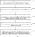
- an audio rendering method including: obtaining a to-be-rendered BRIR signal, where an elevation angle corresponding to the to-be-rendered BRIR signal is 0 degrees; obtaining a direct sound signal based on the to-be-rendered BRIR signal; correcting, based on a target elevation angle, a frequency-domain signal corresponding to the direct sound signal, to obtain a frequency-domain signal corresponding to the target elevation angle; obtaining a time-domain signal based on the corrected frequency-domain signal; and superposing the time-domain signal on a signal that is in the to-be-rendered BRIR signal and that is in a second time period after a first time period, to obtain a BRIR signal of the target elevation angle.
- the direct sound signal corresponds to the first time period in a time period corresponding to the to-be-rendered BRIR signal.
- a target BRIR signal synthesized by the signal in the second time period and the time-domain signal is a stereo BRIR signal.
- the correcting, based on a target elevation angle, a frequency-domain signal corresponding to the direct sound signal includes: determining a correction coefficient based on the target elevation angle and a correction function; and correcting, based on the correction coefficient, the frequency-domain signal corresponding to the direct sound signal, to obtain the corrected frequency-domain signal.
- the correction function includes a numerical relationship between coefficients of HRTF signals corresponding to different elevation angles.
- the correction coefficient may be determined based on the target elevation angle and the correction function corresponding to the target elevation angle.
- the correction coefficient may be a vector including a group of coefficients.
- the correction coefficient is used to process the frequency-domain signal corresponding to the direct sound signal, so that an obtained corrected frequency-domain signal corresponds to the target elevation angle. Therefore, a method for correcting the frequency-domain signal corresponding to the direct sound is provided, so that the corrected frequency-domain signal can correspond to the target elevation angle.
- the obtaining a time-domain signal based on the corrected frequency-domain signal includes: determining an energy adjustment coefficient based on the target elevation angle and an energy adjustment function; adjusting the corrected frequency-domain signal based on the energy adjustment coefficient to obtain an adjusted frequency-domain signal; and performing frequency-time conversion on the adjusted frequency-domain signal to obtain the time-domain signal.
- the energy adjustment function includes a numerical relationship between frequency band energy of the HRTF signals corresponding to different elevation angles.
- the energy adjustment coefficient may be determined based on the target elevation angle and the energy adjustment function. Because the energy adjustment function includes the numerical relationship between frequency band energy of the HRTF signals corresponding to different elevation angles, the energy adjustment coefficient can represent a difference between frequency band energy distributions of the signals.
- the corrected frequency-domain signal is adjusted based on the energy adjustment coefficient, to adjust a frequency band energy distribution of the corrected frequency-domain signal, so as to reduce a problem that a sound disappears at an eccentric ear valley point, and optimize a stereo effect.
- the obtaining a direct sound signal based on the to-be-rendered BRIR signal includes: extracting a signal in the first time period from the to-be-rendered BRIR signal, and processing the signal in the first time period by using a Hanning window, to obtain the direct sound signal.
- windowing processing is performed on the signal in the first time period by using the Hanning window, so that a truncation effect in a time-frequency conversion process can be eliminated, interference caused by trunk scattering can be reduced, and accuracy of the signal can be improved.
- a Hamming window may alternatively be used to perform windowing processing on the signal in the first time period.
- the obtaining a direct sound signal based on the to-be-rendered BRIR signal includes: extracting a signal in the first time period from the to-be-rendered BRIR signal, and processing the signal in the first time period by using a Hanning window, to obtain the direct sound signal.
- the obtaining a time-domain signal based on the corrected frequency-domain signal includes: superposing a spectrum of the corrected frequency-domain signal on a spectrum detail, and performing frequency-time conversion on a signal corresponding to a spectrum obtained through superposition, to obtain the time-domain signal.
- the spectrum detail is a difference between a spectrum of the signal in the first time period and a spectrum of the direct sound signal, and may represent an audio signal lost in a windowing process.
- the corrected frequency-domain signal is corrected by using the spectrum detail, to increase the audio signal lost in the windowing process, so as to better restore the BRIR signal and achieve a better simulation effect.
- the obtaining a direct sound signal based on the to-be-rendered BRIR signal includes: extracting a signal in the first time period from the to-be-rendered BRIR signal, and processing the signal in the first time period by using a Hanning window, to obtain the direct sound signal.
- the obtaining a time-domain signal based on the corrected frequency-domain signal includes: superposing a spectrum of the corrected frequency-domain signal on a spectrum detail, where the spectrum detail is a difference between a spectrum of the signal in the first time period and a spectrum of the direct sound signal; determining an energy adjustment coefficient based on the target elevation angle and an energy adjustment function; adjusting, based on the energy adjustment coefficient, a signal corresponding to a spectrum obtained through superposition, to obtain an adjusted frequency-domain signal; and performing frequency-time conversion on the adjusted frequency-domain signal to obtain the time-domain signal.
- the energy adjustment function includes a numerical relationship between frequency band energy of the HRTF signals corresponding to different elevation angles.
- the signal corresponding to the spectrum obtained through is adjusted by using the energy adjustment coefficient, so that a frequency band energy distribution of the signal corresponding to the spectrum obtained through superposition can be adjusted, and a stereo effect can be optimized.
- an audio rendering method including: obtaining a to-be-rendered BRIR signal, where an elevation angle corresponding to the to-be-rendered BRIR signal is 0 degrees; correcting, based on a target elevation angle, a frequency-domain signal corresponding to the to-be-rendered BRIR signal; and performing frequency-time conversion on a corrected frequency-domain signal to obtain a BRIR signal of the target elevation angle.
- the frequency-domain signal corresponding to the to-be-rendered BRIR signal is corrected based on the target elevation angle, so that the BRIR signal corresponding to the target elevation angle can be obtained. Therefore, a method for implementing a stereo BRIR signal is provided.
- the correcting, based on a target elevation angle, a frequency-domain signal corresponding to the to-be-rendered BRIR signal includes: determining a correction coefficient based on the target elevation angle and a correction function; and processing, by using the correction coefficient, the frequency-domain signal corresponding to the to-be-rendered BRIR signal, to obtain the corrected frequency-domain signal.
- the correction function includes a numerical correspondence between spectrums of HRTF signals corresponding to different elevation angles.
- the correction coefficient may be determined based on the target elevation angle and the correction function corresponding to the target elevation angle.
- the correction coefficient may be a vector including a group of coefficients, and each coefficient corresponds to one frequency-domain signal point.
- the correction coefficient is used to process the frequency-domain signal corresponding to the to-be-rendered BRIR signal, so that an obtained corrected frequency-domain signal corresponds to the target elevation angle. Therefore, a method for correcting the to-be-rendered BRIR signal is provided, so that the corrected frequency-domain signal can correspond to the target elevation angle.
- an audio rendering method including: obtaining a to-be-rendered BRIR signal, where an elevation angle corresponding to the to-be-rendered BRIR signal is 0 degrees; obtaining an HRTF spectrum corresponding to a target elevation angle; and correcting the to-be-rendered BRIR signal based on the HRTF spectrum corresponding to the target elevation angle, to obtain a BRIR signal of the target elevation angle.
- a correction coefficient may be determined based on the HRTF spectrum corresponding to the target elevation angle. The correction coefficient is used to process a frequency-domain signal corresponding to the to-be-rendered BRIR signal, so that an obtained corrected frequency-domain signal corresponds to the target elevation angle. Therefore, another method for obtaining a stereo BRIR signal is provided.
- an audio rendering apparatus may include an entity such as a terminal device or a chip, and the audio rendering apparatus includes a processor and a memory.
- the memory is configured to store instructions
- the processor is configured to execute the instructions in the memory, to enable the audio rendering apparatus to perform the method according to any one of the first aspect, the second aspect, or the third aspect.
- a computer-readable storage medium stores instructions, and when the instructions are run on a computer, the computer is enabled to perform the method according to the foregoing aspects.
- a computer program product including instructions is provided.
- the computer program product runs on a computer, the computer is enabled to perform the method according to the foregoing aspects.
- FIG. 1 is a schematic structural diagram of an audio signal system according to an embodiment of this application.
- the audio signal system includes an audio signal transmit end 11 and an audio signal receive end 12.
- the audio signal transmit end 11 is configured to collect and encode a signal sent by a sound source, to obtain an audio signal encoded bitstream. After obtaining the audio signal encoded bitstream, the audio signal receive end 12 decodes the audio signal encoded bitstream, to obtain a decoded audio signal; and then renders the decoded audio signal to obtain a rendered audio signal.
- the audio signal transmit end 11 may be connected to the audio signal receive end 12 in a wired or wireless manner.
- FIG. 2 is a diagram of a system architecture according to an embodiment of this application.
- the system architecture includes a mobile terminal 21 and a mobile terminal 22.
- the mobile terminal 21 may be an audio signal transmit end
- the mobile terminal 22 may be an audio signal receive end.
- the mobile terminal 21 may include a collection component 211, an encoding component 212, and a channel encoding component 213.
- the collection component 211 is connected to the encoding component 212
- the encoding component 212 is connected to the channel encoding component 213.
- the mobile terminal 22 may include a channel decoding component 221, a decoding and rendering component 222, and an audio playing component 223.
- the decoding and rendering component 222 is connected to the channel decoding component 221
- the audio playing component 223 is connected to the decoding and rendering component 222.
- the mobile terminal 21 sends the transmission signal to the mobile terminal 22 through the wireless or wired network.
- the mobile terminal 22 After receiving the transmission signal, the mobile terminal 22 decodes the transmission signal through the channel decoding component 221, to obtain the audio signal encoded bitstream. Through the decoding and rendering component 222, the mobile terminal 22 decodes the audio signal encoded bitstream, to obtain a to-be-processed audio signal, and renders the to-be-processed audio signal, to obtain a rendered audio signal. Then, the mobile terminal 22 plays the rendered audio signal through the audio playing component 223. It may be understood that the mobile terminal 21 may alternatively include the components included in the mobile terminal 22, and the mobile terminal 22 may alternatively include the components included in the mobile terminal 21.
- the mobile terminal 22 may alternatively include an audio playing component, a decoding component, a rendering component, and a channel decoding component.
- the channel decoding component is connected to the decoding component
- the decoding component is connected to the rendering component
- the rendering component is connected to the audio playing component.
- the mobile terminal 22 decodes the transmission signal through the channel decoding component, to obtain the audio signal encoded bitstream; decodes the audio signal encoded bitstream through the decoding component, to obtain a to-be-processed audio signal; renders the to-be-processed audio signal through the rendering component, to obtain a rendered audio signal; and plays the rendered audio signal through the audio playing component.
- a BRIR function includes an azimuth parameter.
- a mono (mono) signal or stereo (stereo) signal is used as an audio test signal, and then the BRIR function is used to process the audio test signal to obtain a BRIR signal.
- the BRIR signal may be a convolution of the audio test signal and the BRIR function, and azimuth information of the BRIR signal depends on an azimuth parameter value of the BRIR function.
- a range of an azimuth on a horizontal plane is [0, 360°).
- a head reference point is used as an origin
- an azimuth corresponding to the middle of the face is 0 degrees
- an azimuth of the right ear is 90 degrees
- an azimuth of the left ear is 270 degrees.
- an input audio signal is rendered according to a BRIR function corresponding to 90 degrees, and then a rendered audio signal is output.
- the rendered audio signal is like a sound emitted from a sound source in a right horizontal direction. Because an existing BRIR signal includes azimuth information, the BRIR signal can represent a room pulse response in a horizontal direction.
- the existing BRIR signal does not include an elevation angle parameter. It may be considered that an elevation angle of the existing BRIR signal is 0 degrees, and the existing BRIR signal cannot represent a room impulse response in a vertical direction. Therefore, a sound in three-dimensional space cannot be accurately rendered.
- this application provides an audio rendering method, to render a stereo BRIR signal.
- an embodiment of the audio rendering method provided in this application includes the following steps.
- Step 301 Obtain a to-be-rendered BRIR signal, where an elevation angle corresponding to the to-be-rendered BRIR signal is 0 degrees.
- the to-be-rendered BRIR signal is a sampling signal.
- a sampling frequency is 44.1 kHz
- 88 time-domain signal points may be obtained through sampling within 2 ms and used as the to-be-rendered BRIR signal.
- the direct sound signal corresponds to a first time period in a time period corresponding to the to-be-rendered BRIR signal.
- a signal in the first time period refers to a signal part in the to-be-rendered BRIR signal from a start time to an m th millisecond, where m may be but is not limited to a value in [1, 20].
- the signal in the first time period is an audio signal in a first 2 ms.
- the signal in the first time period may be denoted as brir_1(n), and a frequency-domain signal obtained by converting the signal in the first time period may be denoted as brir_1(f).
- the target elevation angle refers to an included angle between a horizontal plane and a straight line from a virtual sound source to a head reference point, and the head reference point may be a midpoint between two ears.
- a value of the target elevation angle is selected according to an actual application, and may be specifically any value in [-90°, 90°].
- the value of the target elevation angle may be input by a user, or may be preset in an audio rendering apparatus and locally invoked by the audio rendering apparatus.
- Step 304 Obtain a time-domain signal based on the frequency-domain signal of the target elevation angle.
- Step 305 Superpose the time-domain signal on a signal that is in the to-be-rendered BRIR signal and that is in a second time period after the first time period, to obtain a BRIR signal of the target elevation angle.
- the BRIR signal synthesized by the signal in the second time period and the time-domain signal is a stereo BRIR signal.
- step 303 includes: determining a correction coefficient based on the target elevation angle and a correction function; and processing, by using the correction coefficient, the frequency-domain signal corresponding to the direct sound signal, to obtain the corrected frequency-domain signal.
- each elevation angle range has an equal size, and the size of each elevation angle range may be but is not limited to: 5 degrees, 10 degrees, 20 degrees, or 30 degrees.
- the correction function includes a numerical relationship between coefficients of HRTF signals corresponding to different elevation angles.
- the correction function may be obtained based on spectrums of the HRTF signals corresponding to different elevation angles. For example, a first HRTF signal and a second HRTF signal have a same azimuth, but have different elevation angles. A difference between the elevation angles of the two signals is the target elevation angle.
- the correction function of the target elevation angle may be determined based on a spectrum of the first HRTF signal and a spectrum of the second HRTF signal.
- the correction coefficient is determined based on the target elevation angle and the correction function.
- the correction coefficient may be a vector including a group of coefficients, and each frequency-domain signal point has a corresponding coefficient.
- the frequency-domain signal corresponding to the direct sound signal is processed by using the correction coefficient, to obtain the corrected frequency-domain signal.
- brir_2(f) is an amplitude of a frequency-domain signal point whose frequency is f in the frequency-domain signal corresponding to the direct sound signal.
- brir_3(f) is an amplitude of a frequency-domain signal point whose frequency is f in the corrected frequency-domain signal.
- p(f) is a correction coefficient corresponding to the frequency-domain signal point whose frequency is f.
- a value range of f may be but is not limited to [0, 20000 Hz].
- This embodiment provides a method for adjusting the direct sound signal. Because a time-domain signal obtained through adjustment corresponds to the target elevation angle, and the signal in the second time period can reflect audio transformation caused by environmental reflection, a target BRIR signal obtained by superposing the signal in the second time period and the time-domain signal is a stereo BRIR signal.
- step 303 includes: correcting, based on the target elevation angle, at least one piece of information about a peak point and information about a valley point in a spectral envelope corresponding to the direct sound signal, to obtain at least one piece of corrected information about the peak point and the valley point, where the at least one piece of corrected information about the peak point and the valley point corresponds to the target elevation angle; determining a target filter based on the at least one piece of corrected information about the peak point and the valley point; and filtering the direct sound signal by using the target filter, to obtain the corrected frequency-domain signal.
- one or more peak points and one or more valley points exist in the spectral envelope corresponding to the direct sound signal, and at least one piece of information about the peak point includes but is not limited to a center frequency of the peak point, a bandwidth of the peak point, and a gain of the peak point. At least one piece of information about the valley point includes but is not limited to a bandwidth of the valley point and a gain of the valley point.
- One elevation angle corresponds to one group of weights, and each weight in the group corresponds to one piece of information.
- a group of weights corresponding to the center frequency, the bandwidth, and the gain of the peak point include a center frequency weight, a bandwidth weight, and a gain weight.
- a group of weights corresponding to the bandwidth and gain of the valley point includes a bandwidth weight and a gain weight.
- a center frequency weight, a bandwidth weight, and a gain weight of a first peak point are respectively denoted as ( q 1 ,q 2 ,q 3 ).
- a value of q 1 may be but is not limited to any value in [1.4, 1.6], for example, 1.5.
- a value of q 2 may be but is not limited to any value in [1.1, 1.3], for example, 1.2.
- a value of q 3 may be but is not limited to any value in [1.2, 1.4], for example, 1.3.
- f s is a sampling frequency
- Z represents a Z field
- a bandwidth weight and a gain weight of the first valley point are respectively ( q 4 ,q 5 ).
- a value of q 4 may be but is not limited to any value in [1.1, 1.3], for example, 1.2.
- a value of q 5 may be but is not limited to any value in [1.2, 1.4], for example, 1.3.
- the filter of the first peak point and the filter of the first valley point are connected in series to obtain the target filter, and then the target filter is used to filter the direct sound signal to obtain the corrected frequency-domain signal.
- a plurality of peak points and a plurality of valley points may alternatively be selected. Then, a peak point filter corresponding to each peak point is determined based on corrected information of each peak point, and a valley point filter corresponding to each valley point is determined based on corrected information of each valley point. Next, a plurality of determined peak point filters and a plurality of determined valley point filters are cascaded to obtain the target filter. Cascading the plurality of peak point filters and the plurality of valley point filters may be specifically: connecting the plurality of peak point filters in parallel, and then connecting the plurality of parallel peak point filters and the plurality of valley point filters in series.
- both the peak point filter and the valley point filter correspond to the corrected information
- the corrected information is related to the target elevation angle. Therefore, after the direct sound signal is filtered by using the target filter, the obtained corrected frequency-domain signal is related to the target elevation angle. Therefore, another method for obtaining the direct sound frequency-domain signal corresponding to the target elevation angle is provided.
- step 304 includes: determining an energy adjustment coefficient based on the target elevation angle and an energy adjustment function; adjusting the corrected frequency-domain signal based on the energy adjustment coefficient to obtain an adjusted frequency-domain signal; and performing frequency-time conversion on the adjusted frequency-domain signal to obtain the time-domain signal.
- the energy adjustment function includes a numerical relationship between frequency band energy of the HRTF signals corresponding to different elevation angles.
- the energy adjustment coefficient may be determined based on the target elevation angle and the energy adjustment function, and the corrected frequency-domain signal may be adjusted based on the energy adjustment coefficient.
- F( ⁇ ) is the spectrum of the adjusted frequency-domain signal
- brir_3(( ⁇ )) is the spectrum of the corrected frequency-domain signal
- M 0 E ⁇ is the energy adjustment function.
- a value range of q 6 is [1, 2]
- a value range of ⁇ is ⁇ ⁇ 2 , ⁇ 2 .
- ⁇ is a spectrum parameter
- the energy adjustment coefficient can represent a difference between frequency band energy distributions of the signals.
- the corrected frequency-domain signal is adjusted based on the energy adjustment coefficient, to adjust a frequency band energy distribution of the corrected frequency-domain signal, reduce a problem that a sound disappears at an eccentric ear valley point, and optimize a stereo effect.
- step 302 includes: extracting the signal in the first time period from the to-be-rendered BRIR signal, and processing the signal in the first time period by using a Hanning window, to obtain the direct sound signal.
- brir _ 1(n) represents an amplitude of an n th time-domain signal point in the signal in the first period
- brir_2(n) represents an amplitude of an n th time-domain signal point in the direct sound signal
- w(n) represents a weight corresponding to the n th time-domain signal point in the Hanning window function.
- N is a total quantity of time-domain signal points in the signal in the first period or in the direct sound signal.
- a function of windowing is to eliminate a truncation effect in a time-frequency conversion process, reduce interference caused by trunk scattering, and improve accuracy of the signal.
- another window for example, a Hamming window, may alternatively be used to process the signal in the first time period.
- step 302 includes: extracting the signal in the first time period from the to-be-rendered BRIR signal, and processing the signal in the first time period by using a Hanning window, to obtain the direct sound signal.
- Step 304 includes: superposing a spectrum of the corrected frequency-domain signal on a spectrum detail, where the spectrum detail is a difference between a spectrum of the signal in the first time period and a spectrum of the direct sound signal; and performing frequency-time conversion on a signal corresponding to a spectrum obtained through superposition, to obtain the time-domain signal.
- step 302 For noun explanations, specific implementations, and technical effects in step 302, refer to corresponding descriptions in the previous embodiment.
- the spectrum detail is the difference between the spectrum of the signal in the first time period and the spectrum of the direct sound signal
- the spectrum detail may be used to represent an audio signal lost in a windowing process.
- D( ⁇ ) is the spectrum detail
- brir_2( ⁇ ) is the spectrum of the direct sound signal
- brir_1( ⁇ ) is the spectrum of the signal in the first period.
- the spectrum of the corrected frequency-domain signal is superposed on the spectrum detail.
- S( ⁇ ) is the spectrum obtained through superposition
- brir_3( ⁇ ) is the spectrum of the corrected frequency-domain signal.
- the spectrum of the corrected frequency-domain signal may be weighted by using a first weight value, the spectrum detail is weighted by using a second weight value, and then the weighted spectrum information is superposed.
- the corrected frequency-domain signal is superposed on the spectrum detail, to increase a lost audio signal, so as to better restore the BRIR signal and achieve a better simulation effect.
- step 302 includes: extracting the signal in the first time period from the to-be-rendered BRIR signal, and processing the signal in the first time period by using a Hanning window, to obtain the direct sound signal.
- Step 304 includes: superposing a spectrum of the corrected frequency-domain signal on a spectrum detail, where the spectrum detail is a difference between a spectrum of the signal in the first time period and a spectrum of the direct sound signal; determining an energy adjustment coefficient based on the target elevation angle and an energy adjustment function, where the energy adjustment function includes a numerical relationship between frequency band energy of the HRTF signals corresponding to different elevation angles; adjusting, based on the energy adjustment coefficient, a signal corresponding to a spectrum obtained through superposition, to obtain an adjusted frequency-domain signal; and performing frequency-time conversion on the adjusted frequency-domain signal to obtain the time-domain signal.
- step 302 For noun explanations, specific implementations, and technical effects in step 302, refer to corresponding descriptions in the foregoing embodiments.
- the spectrum of the corrected frequency-domain signal is superposed on the spectrum detail.
- S( ⁇ ) is the spectrum obtained through superposition
- brir_3( ⁇ ) is the spectrum of the corrected frequency-domain signal
- D( ⁇ ) is the spectrum detail.
- the signal corresponding to the spectrum obtained through superposition is adjusted based on the energy adjustment coefficient.
- FIG. 4 another embodiment of the audio rendering method provided in this application includes the following steps.
- a method for obtaining the BRIR signal corresponding to the target elevation angle is provided.
- the method has advantages of low calculation complexity and a fast execution speed.
- step 402 includes: determining a correction coefficient based on the target elevation angle and a correction function, where the correction function includes a numerical correspondence between spectrums of HRTF signals corresponding to different elevation angles; and processing, by using the correction coefficient, the frequency-domain signal corresponding to the to-be-rendered BRIR signal, to obtain the corrected frequency-domain signal.
- an embodiment of the audio rendering method provided in this application includes the following steps.
- Step 502 Obtain an HRTF spectrum corresponding to a target elevation angle.
- Step 503 Correct the to-be-rendered BRIR signal based on the HRTF spectrum corresponding to the target elevation angle, to obtain a BRIR signal of the target elevation angle.
- the correction coefficient may be determined based on the HRTF spectrum corresponding to the target elevation angle.
- the correction coefficient is used to process the frequency-domain signal corresponding to the to-be-rendered BRIR signal, so that an obtained corrected frequency-domain signal corresponds to the target elevation angle. Therefore, another method for obtaining a stereo BRIR signal is provided.
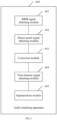
- an embodiment of an audio rendering apparatus 600 provided in this application includes:
- the time-domain signal obtaining module 604 is specifically configured to: determine an energy adjustment coefficient based on the target elevation angle and an energy adjustment function, where the energy adjustment function includes a numerical relationship between frequency band energy of the HRTF signals corresponding to different elevation angles; adjust the corrected frequency-domain signal based on the energy adjustment coefficient to obtain an adjusted frequency-domain signal; and perform frequency-time conversion on the adjusted frequency-domain signal to obtain the time-domain signal.
- the direct sound signal obtaining module 602 is specifically configured to: extract a signal in the first time period from the to-be-rendered BRIR signal; and process the signal in the first time period by using a Hanning window, to obtain the direct sound signal.
- an audio rendering apparatus 700 includes:
- the correction module 702 is specifically configured to: determine a correction coefficient based on the target elevation angle and a correction function, where the correction function includes a numerical relationship between coefficients of HRTF signals corresponding to different elevation angles; and process, by using the correction coefficient, the frequency-domain signal corresponding to the to-be-rendered BRIR signal, to obtain the corrected frequency-domain signal.
- this application provides user equipment 900, configured to implement a function of the audio rendering apparatus 600, the audio rendering apparatus 700, or the audio rendering apparatus 800 in the methods.
- the user equipment 900 includes a processor 901, a memory 902, and an audio circuit 904.
- the processor 901, the memory 902, and the audio circuit 904 are connected by using a bus 903, and the audio circuit 904 is separately connected to a speaker 905 and a microphone 906 by using an audio interface.
- the processor 901 may be a general-purpose processor, including a central processing unit (central processing unit, CPU), a network processor (network processor, NP), or the like.
- the processor 901 may be a digital signal processor (digital signal processing, DSP), an application-specific integrated circuit (application specific integrated circuit, ASIC), a field programmable gate array (field programmable gate array, FPGA) or another programmable logic device, or the like.
- the memory 902 is configured to store a program.
- the program may include program code, and the program code includes computer operation instructions.
- the memory 902 may include a random access memory (random access memory, RAM), and may further include a non-volatile memory (non-volatile memory, NVM), for example, at least one magnetic disk memory.
- the processor 901 executes the program code stored in the memory 902, to implement the method in the embodiment or the optional embodiment shown in FIG. 1, FIG. 2 , or FIG. 3 .
- the audio circuit 904, the speaker 905, and the microphone (microphone) 906 may provide an audio interface between a user and the user equipment 900.
- the audio circuit 904 may convert audio data into an electrical signal, and then transmit the electrical signal to the speaker 905, and the speaker 905 converts the electrical signal into a sound signal for output.
- the microphone 906 may convert a collected sound signal into an electrical signal.
- the audio circuit 904 receives the electrical signal, converts the electrical signal into audio data, and then outputs the audio data to the processor 901 for processing. After the processing, the processor 901 sends the audio data to, for example, other user equipment through a transmitter, or outputs the audio data to the memory 902 for further processing.
- the speaker 905 may be integrated into the user equipment 900, or may be used as an independent device.
- the speaker 905 may be disposed in a headset connected to the user equipment 900.
- All or some of the foregoing embodiments may be implemented by using software, hardware, firmware, or any combination thereof.
- software is used to implement the embodiments, all or some of the embodiments may be implemented in a form of a computer program product.
- the computer program product includes one or more computer instructions.
- the computer may be a general-purpose computer, a dedicated computer, a computer network, or another programmable apparatus.
- the computer instructions may be stored in a computer-readable storage medium or may be transmitted from a computer-readable storage medium to another computer-readable storage medium.
- the computer instructions may be transmitted from a website, computer, server, or data center to another website, computer, server, or data center in a wired (for example, a coaxial cable, an optical fiber, or a digital subscriber line) or wireless (for example, infrared, radio, or microwave) manner.
- wired for example, a coaxial cable, an optical fiber, or a digital subscriber line
- wireless for example, infrared, radio, or microwave
- the computer-readable storage medium may be any usable medium accessible by a computer, or a data storage device, such as a server or a data center, integrating one or more usable media.
- the usable medium may be a magnetic medium (for example, a floppy disk, a hard disk, or a magnetic tape), an optical medium (for example, a DVD), a semiconductor medium (for example, a solid-state drive (solid state disk, SSD)), or the like.
Landscapes
- Engineering & Computer Science (AREA)
- Physics & Mathematics (AREA)
- Acoustics & Sound (AREA)
- Signal Processing (AREA)
- Computational Linguistics (AREA)
- Health & Medical Sciences (AREA)
- Audiology, Speech & Language Pathology (AREA)
- Human Computer Interaction (AREA)
- Multimedia (AREA)
- Spectroscopy & Molecular Physics (AREA)
- Stereophonic System (AREA)
Claims (7)
- Audiowiedergabeverfahren, umfassend:Erhalten (301) eines wiederzugebenden Signals einer binauralen Raumimpulsantwort (BRIR), wobei das wiederzugebende BRIR-Signal ein Abtastsignal ist und ein dem wiederzugebenden BRIR-Signal entsprechender Höhenwinkel 0 Grad beträgt;Erhalten (302) eines Direktschallsignals basierend auf dem wiederzugebenden BRIR-Signal, wobei das Direktschallsignal ein Signal in einem ersten Zeitabschnitt in einem dem wiederzugebenden BRIR-Signal entsprechenden Zeitabschnitt ist und das Signal im ersten Zeitabschnitt ein Signalteil im wiederzugebenden BRIR-Signal von einer Startzeit bis zu einer m-ten Millisekunde ist;Korrigieren (303), basierend auf einem Ziel-Höhenwinkel, eines dem Direktschallsignal entsprechenden Frequenzbereichssignals, wobei das Frequenzbereichssignal durch Umwandeln des Direktschallsignals im ersten Zeitabschnitt erhalten wird, um ein Frequenzbereichssignal des Ziel-Höhenwinkels zu erhalten;Erhalten (304) eines Zeitbereichssignals basierend auf dem Frequenzbereichssignal des Ziel-Höhenwinkels; undÜberlagern (305) des Zeitbereichssignals auf einem Signal, das sich im wiederzugebenden BRIR-Signal befindet und das sich in einem zweiten Zeitabschnitt nach dem ersten Zeitabschnitt befindet, um ein BRIR-Signal des Ziel-Höhenwinkels zu erhalten,wobei das Korrigieren, basierend auf einem Ziel-Höhenwinkel, eines dem Direktschallsignal entsprechenden Frequenzbereichssignals umfasst:Bestimmen eines Korrekturkoeffizienten basierend auf dem Ziel-Höhenwinkel und einer Korrekturfunktion, wobei die Korrekturfunktion eine numerische Beziehung zwischen Koeffizienten von HRTF-Signalen umfasst, die verschiedenen Höhenwinkeln entsprechen; undKorrigieren, basierend auf dem Korrekturkoeffizienten, des dem Direktschallsignal entsprechenden Frequenzbereichssignals, um das korrigierte Frequenzbereichssignal zu erhalten.
- Verfahren nach Anspruch 1, wobei das Erhalten eines Zeitbereichssignals basierend auf dem korrigierten Frequenzbereichssignal umfasst:Bestimmen eines Energieanpassungskoeffizienten basierend auf dem Ziel-Höhenwinkel und einer Energieanpassungsfunktion. wobei die Energieanpassungsfunktion eine numerische Beziehung zwischen der Frequenzbandenergie der HRTF-Signale umfasst, die verschiedenen Höhenwinkeln entsprechen;Anpassen des korrigierten Frequenzbereichssignals basierend auf dem Energieanpassungskoeffizienten, um ein angepasstes Frequenzbereichssignal zu erhalten; undDurchführen einer Frequenz-Zeit-Konvertierung an dem angepassten Frequenzbereichssignal, um das Zeitbereichssignal zu erhalten.
- Verfahren nach einem der Ansprüche 1 bis 2, wobei das Erhalten eines Direktschallsignals basierend auf dem wiederzugebenden BRIR-Signal umfasst:
Extrahieren eines Signals im ersten Zeitabschnitt aus dem wiederzugebenden BRIR-Signal und Verarbeiten des Signals im ersten Zeitabschnitt unter Verwendung eines Hanning-Fensters, um das Direktschallsignal zu erhalten. - Verfahren nach Anspruch 1, wobei das Erhalten eines Direktschallsignals basierend auf dem wiederzugebenden BRIR-Signal umfasst:Extrahieren eines Signals im ersten Zeitabschnitt aus dem wiederzugebenden BRIR-Signal und Verarbeiten des Signals im ersten Zeitabschnitt unter Verwendung eines Hanning-Fensters, um das Direktschallsignal zu erhalten; undwobei das Erhalten eines Zeitbereichssignals basierend auf dem korrigierten Frequenzbereichssignal umfasst:Überlagern eines Spektrums des korrigierten Frequenzbereichssignals auf einem Spektrumdetail, wobei das Spektrumdetail eine Differenz zwischen einem Spektrum des Signals im ersten Zeitabschnitt und einem Spektrum des Direktschallsignals ist; undDurchführen einer Frequenz-Zeit-Konvertierung an einem Signal, das einem durch Überlagerung erhaltenen Spektrum entspricht, um das Zeitbereichssignal zu erhalten.
- Verfahren nach Anspruch 1, wobei das Erhalten eines Direktschallsignals basierend auf dem wiederzugebenden BRIR-Signal umfasst:Extrahieren eines Signals im ersten Zeitabschnitt aus dem wiederzugebenden BRIR-Signal, undVerarbeiten des Signals im ersten Zeitabschnitt unter Verwendung eines Hanning-Fensters, um das Direktschallsignal zu erhalten; und wobei das Erhalten eines Zeitbereichssignals basierend auf dem korrigierten Frequenzbereichssignal umfasst:Überlagern eines Spektrums des korrigierten Frequenzbereichssignals auf einem Spektrumdetail, wobei das Spektrumdetail eine Differenz zwischen einem Spektrum des Signals im ersten Zeitabschnitt und einem Spektrum des Direktschallsignals ist;Bestimmen eines Energieanpassungskoeffizienten basierend auf dem Ziel-Höhenwinkel und einer Energieanpassungsfunktion. wobei die Energieanpassungsfunktion eine numerische Beziehung zwischen der Frequenzbandenergie der HRTF-Signale umfasst, die verschiedenen Höhenwinkeln entsprechen;Anpassen, basierend auf dem Energieanpassungskoeffizienten, eines Signals, das einem durch Überlagerung erhaltenen Spektrum entspricht, um ein angepasstes Frequenzbereichssignal zu erhalten; undDurchführen einer Frequenz-Zeit-Konvertierung an dem angepassten Frequenzbereichssignal, um das Zeitbereichssignal zu erhalten.
- Audiowiedergabevorrichtung, umfassend:ein BRIR-Signalerhaltungsmodul (601), das konfiguriert ist, um ein wiederzugebendes Signal einer binauralen Raumimpulsantwort (BRIR) zu erhalten, wobei das wiederzugebende BRIR-Signal ein Abtastsignal ist und ein dem wiederzugebenden BRIR-Signal entsprechender Höhenwinkel 0 Grad beträgt;ein Direktschallsignalerhaltungsmodul (602), das konfiguriert ist, um ein Direktschallsignal basierend auf dem wiederzugebenden BRIR-Signal zu erhalten, wobei das Direktschallsignal ein Signal in einem ersten Zeitabschnitt in einem dem wiederzugebenden BRIR-Signal entsprechenden Zeitabschnitt ist und das Signal im ersten Zeitabschnitt ein Signalteil im wiederzugebenden BRIR-Signal von einer Startzeit bis zu einer m-ten Millisekunde ist;ein Korrekturmodul (603), das konfiguriert ist, um basierend auf einem Ziel-Höhenwinkel ein dem Direktschallsignal entsprechendes Frequenzbereichssignal zu korrigieren, wobei das Frequenzbereichssignal durch Umwandeln des Direktschallsignals im ersten Zeitabschnitt erhalten wird, um ein Frequenzbereichssignal des Ziel-Höhenwinkels zu erhalten;ein Zeitbereichssignal-Erhaltungsmodul (604), das konfiguriert ist, um ein Zeitbereichssignal basierend auf dem Frequenzbereichssignal des Ziel-Höhenwinkels zu erhalten; undein Überlagerungsmodul (605), das konfiguriert ist, um das Zeitbereichssignal auf einem Signal zu überlagern, das sich im wiederzugebenden BRIR-Signal befindet und das sich in einem zweiten Zeitabschnitt nach dem ersten Zeitabschnitt befindet, um ein BRIR-Signal des Ziel-Höhenwinkels zu erhalten;wobei das Korrekturmodul konfiguriert ist, um basierend auf einem Ziel-Höhenwinkel ein dem Direktschallsignal entsprechendes Frequenzbereichssignal zu korrigieren durch:Bestimmen eines Korrekturkoeffizienten basierend auf dem Ziel-Höhenwinkel und einer Korrekturfunktion, wobei die Korrekturfunktion eine numerische Beziehung zwischen Koeffizienten von HRTF-Signalen umfasst, die verschiedenen Höhenwinkeln entsprechen; undKorrigieren, basierend auf dem Korrekturkoeffizienten, des dem Direktschallsignal entsprechenden Frequenzbereichssignals, um das korrigierte Frequenzbereichssignal zu erhalten.
- Computerspeichermedium, das Anweisungen umfasst, wobei, wenn die Anweisungen auf einem Computer ausgeführt werden, der Computer das Verfahren nach einem der Ansprüche 1 bis 5 durchführen kann.
Applications Claiming Priority (2)
| Application Number | Priority Date | Filing Date | Title |
|---|---|---|---|
| CN201811261215.3A CN111107481B (zh) | 2018-10-26 | 2018-10-26 | 一种音频渲染方法及装置 |
| PCT/CN2019/111620 WO2020083088A1 (zh) | 2018-10-26 | 2019-10-17 | 一种音频渲染方法及装置 |
Publications (3)
| Publication Number | Publication Date |
|---|---|
| EP3866485A1 EP3866485A1 (de) | 2021-08-18 |
| EP3866485A4 EP3866485A4 (de) | 2021-12-08 |
| EP3866485B1 true EP3866485B1 (de) | 2025-03-26 |
Family
ID=70331882
Family Applications (1)
| Application Number | Title | Priority Date | Filing Date |
|---|---|---|---|
| EP19876377.3A Active EP3866485B1 (de) | 2018-10-26 | 2019-10-17 | Verfahren und vorrichtung zur wiedergabe von audio |
Country Status (4)
| Country | Link |
|---|---|
| US (1) | US11445324B2 (de) |
| EP (1) | EP3866485B1 (de) |
| CN (1) | CN111107481B (de) |
| WO (1) | WO2020083088A1 (de) |
Families Citing this family (2)
| Publication number | Priority date | Publication date | Assignee | Title |
|---|---|---|---|---|
| CN116055983B (zh) * | 2022-08-30 | 2023-11-07 | 荣耀终端有限公司 | 一种音频信号处理方法及电子设备 |
| CN119541512A (zh) * | 2023-08-29 | 2025-02-28 | 华为技术有限公司 | 一种渲染声音的方法以及电子设备 |
Family Cites Families (22)
| Publication number | Priority date | Publication date | Assignee | Title |
|---|---|---|---|---|
| WO2007096808A1 (en) * | 2006-02-21 | 2007-08-30 | Koninklijke Philips Electronics N.V. | Audio encoding and decoding |
| US20120093323A1 (en) * | 2010-10-14 | 2012-04-19 | Samsung Electronics Co., Ltd. | Audio system and method of down mixing audio signals using the same |
| EP2464145A1 (de) * | 2010-12-10 | 2012-06-13 | Fraunhofer-Gesellschaft zur Förderung der angewandten Forschung e.V. | Vorrichtung und Verfahren zur Dekomposition eines Eingabesignals mit einem Downmixer |
| CN102665156B (zh) * | 2012-03-27 | 2014-07-02 | 中国科学院声学研究所 | 一种基于耳机的虚拟3d重放方法 |
| EP2943952A1 (de) * | 2013-01-14 | 2015-11-18 | Koninklijke Philips N.V. | Mehrkanaliger codierer und decodierer mit effizienter übertragung von positionsinformationen |
| CN108810793B (zh) * | 2013-04-19 | 2020-12-15 | 韩国电子通信研究院 | 多信道音频信号处理装置及方法 |
| US9384741B2 (en) * | 2013-05-29 | 2016-07-05 | Qualcomm Incorporated | Binauralization of rotated higher order ambisonics |
| EP2830043A3 (de) * | 2013-07-22 | 2015-02-18 | Fraunhofer-Gesellschaft zur Förderung der angewandten Forschung e.V. | Verfahren zur Verarbeitung eines Audiosignals in Übereinstimmung mit einer Raumimpulsantwort, Signalverarbeitungseinheit, Audiocodierer, Audiodecodierer und binauraler Renderer |
| US9832589B2 (en) * | 2013-12-23 | 2017-11-28 | Wilus Institute Of Standards And Technology Inc. | Method for generating filter for audio signal, and parameterization device for same |
| CN105900457B (zh) * | 2014-01-03 | 2017-08-15 | 杜比实验室特许公司 | 用于设计和应用数值优化的双耳房间脉冲响应的方法和系统 |
| KR102216657B1 (ko) * | 2014-04-02 | 2021-02-17 | 주식회사 윌러스표준기술연구소 | 오디오 신호 처리 방법 및 장치 |
| KR101856127B1 (ko) * | 2014-04-02 | 2018-05-09 | 주식회사 윌러스표준기술연구소 | 오디오 신호 처리 방법 및 장치 |
| EP4583542A3 (de) * | 2014-04-02 | 2025-08-06 | Wilus Institute of Standards and Technology Inc. | Audiosignalverarbeitungsverfahren und -vorrichtung |
| CN104240695A (zh) * | 2014-08-29 | 2014-12-24 | 华南理工大学 | 一种优化的基于耳机重放的虚拟声合成方法 |
| EP3001701B1 (de) * | 2014-09-24 | 2018-11-14 | Harman Becker Automotive Systems GmbH | Audiowiedergabesysteme und -verfahren |
| US9560467B2 (en) * | 2014-11-11 | 2017-01-31 | Google Inc. | 3D immersive spatial audio systems and methods |
| WO2016180680A1 (en) * | 2015-05-08 | 2016-11-17 | Nagravision S.A. | Method for rendering audio-video content, decoder for implementing this method and rendering device for rendering this audio-video content |
| CN108476370B (zh) * | 2015-10-26 | 2022-01-25 | 弗劳恩霍夫应用研究促进协会 | 用于生成实现仰角渲染的滤波后的音频信号的装置和方法 |
| WO2017192972A1 (en) * | 2016-05-06 | 2017-11-09 | Dts, Inc. | Immersive audio reproduction systems |
| JP7038725B2 (ja) * | 2017-02-10 | 2022-03-18 | ガウディオ・ラボ・インコーポレイテッド | オーディオ信号処理方法及び装置 |
| WO2019004524A1 (ko) * | 2017-06-27 | 2019-01-03 | 엘지전자 주식회사 | 6자유도 환경에서 오디오 재생 방법 및 오디오 재생 장치 |
| US10390171B2 (en) * | 2018-01-07 | 2019-08-20 | Creative Technology Ltd | Method for generating customized spatial audio with head tracking |
-
2018
- 2018-10-26 CN CN201811261215.3A patent/CN111107481B/zh active Active
-
2019
- 2019-10-17 EP EP19876377.3A patent/EP3866485B1/de active Active
- 2019-10-17 WO PCT/CN2019/111620 patent/WO2020083088A1/zh not_active Ceased
-
2021
- 2021-04-26 US US17/240,655 patent/US11445324B2/en active Active
Also Published As
| Publication number | Publication date |
|---|---|
| CN111107481B (zh) | 2021-06-22 |
| CN111107481A (zh) | 2020-05-05 |
| US20210250723A1 (en) | 2021-08-12 |
| WO2020083088A1 (zh) | 2020-04-30 |
| US11445324B2 (en) | 2022-09-13 |
| EP3866485A4 (de) | 2021-12-08 |
| EP3866485A1 (de) | 2021-08-18 |
Similar Documents
| Publication | Publication Date | Title |
|---|---|---|
| EP3229498B1 (de) | Audiosignalverarbeitungsvorrichtung und -verfahren zum binauralen rendering | |
| EP3520104B1 (de) | Erzeugung eines räumlichen tonsignalformats aus einer mikrofonanordnung mit adaptiver erfassung | |
| US9763020B2 (en) | Virtual stereo synthesis method and apparatus | |
| CN103165136A (zh) | 音频处理方法及音频处理设备 | |
| US20170188175A1 (en) | Audio signal processing method and device | |
| EP4246510A1 (de) | Verfahren und vorrichtung zur audiokodierung und -dekodierung | |
| EP3776544A1 (de) | Parameter von räumlichem audio und zugehörige wiedergabe von räumlichem audio | |
| JP2020506639A (ja) | オーディオ信号処理方法及び装置 | |
| CN103348703A (zh) | 用以利用预先算出的参考曲线来分解输入信号的装置和方法 | |
| MX2013013058A (es) | Aparato y metodo para generar una señal de salida que emplea un descomponedor. | |
| US11910180B2 (en) | Audio processing method and apparatus | |
| WO2016056410A1 (ja) | 音声処理装置および方法、並びにプログラム | |
| US20240355342A1 (en) | Inter-channel phase difference parameter encoding method and apparatus | |
| US11445324B2 (en) | Audio rendering method and apparatus | |
| US20250365552A1 (en) | Binaural signal post-processing | |
| US20210250717A1 (en) | Spatial audio Capture, Transmission and Reproduction | |
| US11863964B2 (en) | Audio processing method and apparatus | |
| Lee et al. | HRTF measurement for accurate sound localization cues | |
| EP4322158A1 (de) | Verfahren und vorrichtung zur codierung dreidimensionaler audiosignale und codierer | |
| Hammond et al. | Robust full-sphere binaural sound source localization | |
| CN116261086B (zh) | 声音信号处理方法、装置、设备及存储介质 | |
| Hammond et al. | Robust median-plane binaural sound source localization | |
| CN112584300B (zh) | 音频上混方法、装置、电子设备和存储介质 | |
| WO2024202997A1 (ja) | チャネル間時間差推定装置、及び、チャネル間時間差推定方法 | |
| EP4325485A1 (de) | Verfahren und vorrichtung zur codierung dreidimensionaler audiosignale und codierer |
Legal Events
| Date | Code | Title | Description |
|---|---|---|---|
| STAA | Information on the status of an ep patent application or granted ep patent |
Free format text: STATUS: THE INTERNATIONAL PUBLICATION HAS BEEN MADE |
|
| PUAI | Public reference made under article 153(3) epc to a published international application that has entered the european phase |
Free format text: ORIGINAL CODE: 0009012 |
|
| STAA | Information on the status of an ep patent application or granted ep patent |
Free format text: STATUS: REQUEST FOR EXAMINATION WAS MADE |
|
| 17P | Request for examination filed |
Effective date: 20210511 |
|
| AK | Designated contracting states |
Kind code of ref document: A1 Designated state(s): AL AT BE BG CH CY CZ DE DK EE ES FI FR GB GR HR HU IE IS IT LI LT LU LV MC MK MT NL NO PL PT RO RS SE SI SK SM TR |
|
| REG | Reference to a national code |
Ref country code: DE Ipc: H04S0007000000 Ref legal event code: R079 Ref document number: 602019067913 Country of ref document: DE Free format text: PREVIOUS MAIN CLASS: H04R0001200000 |
|
| A4 | Supplementary search report drawn up and despatched |
Effective date: 20211110 |
|
| RIC1 | Information provided on ipc code assigned before grant |
Ipc: H04S 7/00 20060101AFI20211104BHEP |
|
| DAV | Request for validation of the european patent (deleted) | ||
| DAX | Request for extension of the european patent (deleted) | ||
| STAA | Information on the status of an ep patent application or granted ep patent |
Free format text: STATUS: EXAMINATION IS IN PROGRESS |
|
| 17Q | First examination report despatched |
Effective date: 20230324 |
|
| GRAP | Despatch of communication of intention to grant a patent |
Free format text: ORIGINAL CODE: EPIDOSNIGR1 |
|
| STAA | Information on the status of an ep patent application or granted ep patent |
Free format text: STATUS: GRANT OF PATENT IS INTENDED |
|
| INTG | Intention to grant announced |
Effective date: 20241115 |
|
| GRAS | Grant fee paid |
Free format text: ORIGINAL CODE: EPIDOSNIGR3 |
|
| GRAA | (expected) grant |
Free format text: ORIGINAL CODE: 0009210 |
|
| STAA | Information on the status of an ep patent application or granted ep patent |
Free format text: STATUS: THE PATENT HAS BEEN GRANTED |
|
| P01 | Opt-out of the competence of the unified patent court (upc) registered |
Free format text: CASE NUMBER: APP_4438/2025 Effective date: 20250127 |
|
| AK | Designated contracting states |
Kind code of ref document: B1 Designated state(s): AL AT BE BG CH CY CZ DE DK EE ES FI FR GB GR HR HU IE IS IT LI LT LU LV MC MK MT NL NO PL PT RO RS SE SI SK SM TR |
|
| REG | Reference to a national code |
Ref country code: GB Ref legal event code: FG4D |
|
| REG | Reference to a national code |
Ref country code: CH Ref legal event code: EP |
|
| REG | Reference to a national code |
Ref country code: DE Ref legal event code: R096 Ref document number: 602019067913 Country of ref document: DE |
|
| REG | Reference to a national code |
Ref country code: IE Ref legal event code: FG4D |
|
| PG25 | Lapsed in a contracting state [announced via postgrant information from national office to epo] |
Ref country code: RS Free format text: LAPSE BECAUSE OF FAILURE TO SUBMIT A TRANSLATION OF THE DESCRIPTION OR TO PAY THE FEE WITHIN THE PRESCRIBED TIME-LIMIT Effective date: 20250626 |
|
| PG25 | Lapsed in a contracting state [announced via postgrant information from national office to epo] |
Ref country code: FI Free format text: LAPSE BECAUSE OF FAILURE TO SUBMIT A TRANSLATION OF THE DESCRIPTION OR TO PAY THE FEE WITHIN THE PRESCRIBED TIME-LIMIT Effective date: 20250326 |
|
| REG | Reference to a national code |
Ref country code: LT Ref legal event code: MG9D |
|
| PG25 | Lapsed in a contracting state [announced via postgrant information from national office to epo] |
Ref country code: NO Free format text: LAPSE BECAUSE OF FAILURE TO SUBMIT A TRANSLATION OF THE DESCRIPTION OR TO PAY THE FEE WITHIN THE PRESCRIBED TIME-LIMIT Effective date: 20250626 |
|
| PG25 | Lapsed in a contracting state [announced via postgrant information from national office to epo] |
Ref country code: HR Free format text: LAPSE BECAUSE OF FAILURE TO SUBMIT A TRANSLATION OF THE DESCRIPTION OR TO PAY THE FEE WITHIN THE PRESCRIBED TIME-LIMIT Effective date: 20250326 |
|
| PG25 | Lapsed in a contracting state [announced via postgrant information from national office to epo] |
Ref country code: LV Free format text: LAPSE BECAUSE OF FAILURE TO SUBMIT A TRANSLATION OF THE DESCRIPTION OR TO PAY THE FEE WITHIN THE PRESCRIBED TIME-LIMIT Effective date: 20250326 |
|
| PG25 | Lapsed in a contracting state [announced via postgrant information from national office to epo] |
Ref country code: GR Free format text: LAPSE BECAUSE OF FAILURE TO SUBMIT A TRANSLATION OF THE DESCRIPTION OR TO PAY THE FEE WITHIN THE PRESCRIBED TIME-LIMIT Effective date: 20250627 Ref country code: BG Free format text: LAPSE BECAUSE OF FAILURE TO SUBMIT A TRANSLATION OF THE DESCRIPTION OR TO PAY THE FEE WITHIN THE PRESCRIBED TIME-LIMIT Effective date: 20250326 |
|
| REG | Reference to a national code |
Ref country code: NL Ref legal event code: MP Effective date: 20250326 |
|
| PG25 | Lapsed in a contracting state [announced via postgrant information from national office to epo] |
Ref country code: NL Free format text: LAPSE BECAUSE OF FAILURE TO SUBMIT A TRANSLATION OF THE DESCRIPTION OR TO PAY THE FEE WITHIN THE PRESCRIBED TIME-LIMIT Effective date: 20250326 |
|
| PG25 | Lapsed in a contracting state [announced via postgrant information from national office to epo] |
Ref country code: SE Free format text: LAPSE BECAUSE OF FAILURE TO SUBMIT A TRANSLATION OF THE DESCRIPTION OR TO PAY THE FEE WITHIN THE PRESCRIBED TIME-LIMIT Effective date: 20250326 |
|
| REG | Reference to a national code |
Ref country code: AT Ref legal event code: MK05 Ref document number: 1780195 Country of ref document: AT Kind code of ref document: T Effective date: 20250326 |
|
| PG25 | Lapsed in a contracting state [announced via postgrant information from national office to epo] |
Ref country code: SM Free format text: LAPSE BECAUSE OF FAILURE TO SUBMIT A TRANSLATION OF THE DESCRIPTION OR TO PAY THE FEE WITHIN THE PRESCRIBED TIME-LIMIT Effective date: 20250326 |
|
| PG25 | Lapsed in a contracting state [announced via postgrant information from national office to epo] |
Ref country code: PT Free format text: LAPSE BECAUSE OF FAILURE TO SUBMIT A TRANSLATION OF THE DESCRIPTION OR TO PAY THE FEE WITHIN THE PRESCRIBED TIME-LIMIT Effective date: 20250728 Ref country code: ES Free format text: LAPSE BECAUSE OF FAILURE TO SUBMIT A TRANSLATION OF THE DESCRIPTION OR TO PAY THE FEE WITHIN THE PRESCRIBED TIME-LIMIT Effective date: 20250326 |
|
| PG25 | Lapsed in a contracting state [announced via postgrant information from national office to epo] |
Ref country code: IT Free format text: LAPSE BECAUSE OF FAILURE TO SUBMIT A TRANSLATION OF THE DESCRIPTION OR TO PAY THE FEE WITHIN THE PRESCRIBED TIME-LIMIT Effective date: 20250326 Ref country code: PL Free format text: LAPSE BECAUSE OF FAILURE TO SUBMIT A TRANSLATION OF THE DESCRIPTION OR TO PAY THE FEE WITHIN THE PRESCRIBED TIME-LIMIT Effective date: 20250326 |
|
| PGFP | Annual fee paid to national office [announced via postgrant information from national office to epo] |
Ref country code: GB Payment date: 20250904 Year of fee payment: 7 |
|
| PG25 | Lapsed in a contracting state [announced via postgrant information from national office to epo] |
Ref country code: AT Free format text: LAPSE BECAUSE OF FAILURE TO SUBMIT A TRANSLATION OF THE DESCRIPTION OR TO PAY THE FEE WITHIN THE PRESCRIBED TIME-LIMIT Effective date: 20250326 |
|
| PG25 | Lapsed in a contracting state [announced via postgrant information from national office to epo] |
Ref country code: EE Free format text: LAPSE BECAUSE OF FAILURE TO SUBMIT A TRANSLATION OF THE DESCRIPTION OR TO PAY THE FEE WITHIN THE PRESCRIBED TIME-LIMIT Effective date: 20250326 |
|
| PG25 | Lapsed in a contracting state [announced via postgrant information from national office to epo] |
Ref country code: RO Free format text: LAPSE BECAUSE OF FAILURE TO SUBMIT A TRANSLATION OF THE DESCRIPTION OR TO PAY THE FEE WITHIN THE PRESCRIBED TIME-LIMIT Effective date: 20250326 |
|
| PG25 | Lapsed in a contracting state [announced via postgrant information from national office to epo] |
Ref country code: SK Free format text: LAPSE BECAUSE OF FAILURE TO SUBMIT A TRANSLATION OF THE DESCRIPTION OR TO PAY THE FEE WITHIN THE PRESCRIBED TIME-LIMIT Effective date: 20250326 |
|
| PG25 | Lapsed in a contracting state [announced via postgrant information from national office to epo] |
Ref country code: IS Free format text: LAPSE BECAUSE OF FAILURE TO SUBMIT A TRANSLATION OF THE DESCRIPTION OR TO PAY THE FEE WITHIN THE PRESCRIBED TIME-LIMIT Effective date: 20250726 |
|
| REG | Reference to a national code |
Ref country code: DE Ref legal event code: R097 Ref document number: 602019067913 Country of ref document: DE |
|
| PGFP | Annual fee paid to national office [announced via postgrant information from national office to epo] |
Ref country code: DE Payment date: 20250902 Year of fee payment: 7 |
|
| PG25 | Lapsed in a contracting state [announced via postgrant information from national office to epo] |
Ref country code: DK Free format text: LAPSE BECAUSE OF FAILURE TO SUBMIT A TRANSLATION OF THE DESCRIPTION OR TO PAY THE FEE WITHIN THE PRESCRIBED TIME-LIMIT Effective date: 20250326 |
|
| PG25 | Lapsed in a contracting state [announced via postgrant information from national office to epo] |
Ref country code: CZ Free format text: LAPSE BECAUSE OF FAILURE TO SUBMIT A TRANSLATION OF THE DESCRIPTION OR TO PAY THE FEE WITHIN THE PRESCRIBED TIME-LIMIT Effective date: 20250326 |
|
| PLBE | No opposition filed within time limit |
Free format text: ORIGINAL CODE: 0009261 |
|
| STAA | Information on the status of an ep patent application or granted ep patent |
Free format text: STATUS: NO OPPOSITION FILED WITHIN TIME LIMIT |
|
| REG | Reference to a national code |
Ref country code: CH Ref legal event code: L10 Free format text: ST27 STATUS EVENT CODE: U-0-0-L10-L00 (AS PROVIDED BY THE NATIONAL OFFICE) Effective date: 20260211 |
|
| 26N | No opposition filed |
Effective date: 20260105 |