EP3865908B1 - Bistatic sar phase synchronization signal processing method and device - Google Patents
Bistatic sar phase synchronization signal processing method and device Download PDFInfo
- Publication number
- EP3865908B1 EP3865908B1 EP20176890.0A EP20176890A EP3865908B1 EP 3865908 B1 EP3865908 B1 EP 3865908B1 EP 20176890 A EP20176890 A EP 20176890A EP 3865908 B1 EP3865908 B1 EP 3865908B1
- Authority
- EP
- European Patent Office
- Prior art keywords
- radar
- signal
- phase synchronization
- phase
- synchronization signal
- Prior art date
- Legal status (The legal status is an assumption and is not a legal conclusion. Google has not performed a legal analysis and makes no representation as to the accuracy of the status listed.)
- Active
Links
Images




Classifications
-
- G—PHYSICS
- G01—MEASURING; TESTING
- G01S—RADIO DIRECTION-FINDING; RADIO NAVIGATION; DETERMINING DISTANCE OR VELOCITY BY USE OF RADIO WAVES; LOCATING OR PRESENCE-DETECTING BY USE OF THE REFLECTION OR RERADIATION OF RADIO WAVES; ANALOGOUS ARRANGEMENTS USING OTHER WAVES
- G01S13/00—Systems using the reflection or reradiation of radio waves, e.g. radar systems; Analogous systems using reflection or reradiation of waves whose nature or wavelength is irrelevant or unspecified
- G01S13/88—Radar or analogous systems specially adapted for specific applications
- G01S13/89—Radar or analogous systems specially adapted for specific applications for mapping or imaging
- G01S13/90—Radar or analogous systems specially adapted for specific applications for mapping or imaging using synthetic aperture techniques, e.g. synthetic aperture radar [SAR] techniques
- G01S13/904—SAR modes
- G01S13/9058—Bistatic or multistatic SAR
-
- G—PHYSICS
- G01—MEASURING; TESTING
- G01S—RADIO DIRECTION-FINDING; RADIO NAVIGATION; DETERMINING DISTANCE OR VELOCITY BY USE OF RADIO WAVES; LOCATING OR PRESENCE-DETECTING BY USE OF THE REFLECTION OR RERADIATION OF RADIO WAVES; ANALOGOUS ARRANGEMENTS USING OTHER WAVES
- G01S7/00—Details of systems according to groups G01S13/00, G01S15/00, G01S17/00
- G01S7/02—Details of systems according to groups G01S13/00, G01S15/00, G01S17/00 of systems according to group G01S13/00
- G01S7/40—Means for monitoring or calibrating
-
- G—PHYSICS
- G01—MEASURING; TESTING
- G01S—RADIO DIRECTION-FINDING; RADIO NAVIGATION; DETERMINING DISTANCE OR VELOCITY BY USE OF RADIO WAVES; LOCATING OR PRESENCE-DETECTING BY USE OF THE REFLECTION OR RERADIATION OF RADIO WAVES; ANALOGOUS ARRANGEMENTS USING OTHER WAVES
- G01S7/00—Details of systems according to groups G01S13/00, G01S15/00, G01S17/00
- G01S7/02—Details of systems according to groups G01S13/00, G01S15/00, G01S17/00 of systems according to group G01S13/00
- G01S7/41—Details of systems according to groups G01S13/00, G01S15/00, G01S17/00 of systems according to group G01S13/00 using analysis of echo signal for target characterisation; Target signature; Target cross-section
Definitions
- the disclosure relates to the technical field of radars, and particularly relates to a Bistatic Synthetic Aperture Radar (BiSAR) phase synchronization signal processing method and device.
- BiSAR Bistatic Synthetic Aperture Radar
- the SAR is an active microwave imaging radar which has the characteristics of all-time and all-weather work, and has unique advantages in applications, such as environmental protection, disaster monitoring, marine observation, resource exploration and military reconnaissance.
- a Bistatic SAR system is a novel radar system. Radars are mounted on two satellites flying in formation to form a bistatic radar system to together complete tasks such as high-resolution imaging of large surveying and mapping areas, ground elevation measurement, ocean current velocity measurement, ground moving target monitoring, and the like.
- the Bistatic SAR system is implemented by transmitting signals through a master satellite and simultaneously receiving the signals through a slave satellite.
- the working mode of the bistatic radar system is that after the master satellite transmits a radar signal, a synchronization signal is transmitted.
- the embodiments of the present specification provide a Bistatic SAR phase synchronization signal processing method and device.
- a first radar transmits a radar signal and a first phase synchronization signal with the same carrier frequency, thereby reducing the opening time of a signal receiving window, and simplifying the design complexity of a radar system.
- the first radar receives a second phase synchronization signal, which has a same carrier frequency as the first phase synchronization signal, transmitted by a second radar, and then, the phase synchronization signal and the radar signal received by the first radar and the second radar have the same carrier frequency, so that there is no need to perform scale transformation on the received phase synchronization signal and then perform phase compensation, and the phase compensation result is more accurate.
- modules such as “modules”, “components” or “units” for representing elements
- suffixes such as “modules”, “components” or “units” for representing elements
- FIG. 1 shows a flowchart of a Bistatic SAR phase synchronization signal processing method based on carrier frequency signals according to some embodiments of the present specification.
- the Bistatic SAR phase synchronization signal processing method based on carrier frequency signals includes the following operations:
- S101 Transmitting, by a first radar a radar signal to a target object and a first phase synchronization signal to a second radar.
- the carrier frequency of the radar signal is the same as that of the first phase synchronization signal.
- the first radar is a master satellite, and the second radar is a slave satellite.
- the first radar is responsible for transmitting a radar signal to a target object, and transmitting a first phase synchronization signal to the second radar in the same pulse period.
- a plurality of second radars may be disposed in the Bistatic SAR system.
- the first radar receives an echo signal reflected by the radar signal, and the second radar receives the echo signal and the first phase synchronization signal.
- the radar signal and the first phase synchronization signal are the same carrier frequency signals which are transmitted by the first radar at the same time in two paths, wherein one path of the carrier frequency signal is mixed with a chirp signal to generate the radar signal, and the other path of the carrier frequency signal directly generates the first phase synchronization signal.
- FIG. 2 shows a schematic diagram of generation of a radar signal and a phase synchronization signal a some embodiments of the present specification.
- 201 is a carrier frequency signal
- 202 is a first phase synchronization signal directly generated by the carrier frequency signal 201
- 203 is a radar signal transmitted by a first radar, obtained by mixing the carrier frequency signal 201 and a chirp signal 204.
- the first radar receives and stores an echo signal reflected by the radar signal to obtain a received signal of the first radar; and the second radar receives and stores the echo signal and the first phase synchronization signal to obtain a received signal of the second radar.
- the second radar may not receive the first phase synchronization signal, and the second radar only stores the echo signal to obtain a received signal of the second radar.
- S102 A second phase synchronization signal transmitted by the second radar is received by the first radar.
- the carrier frequency of the second phase synchronization signal is the same as the carrier frequency of the first phase synchronization signal.
- the second radar After the second radar receives the first phase synchronization signal transmitted by the first radar, in a first time sequence of the second pulse repetition time, the second radar transmits a second phase synchronization signal to the first radar, and the first radar transmits a radar signal to a target object.
- the first radar receives and stores an echo signal reflected by the radar signal and the second phase synchronization signal to obtain a received signal of the first radar; and the second radar receives and stores the echo signal reflected by the radar signal to obtain a received signal of the second radar.
- the first radar may not receive the second phase synchronization signal, and the first radar only stores the echo signal to obtain a received signal of the first radar.
- Phase synchronization compensation is performed on the received signal of the second radar at least according to the first phase synchronization signal and the second phase synchronization signal.
- phase adjustment is performed on the received signal of the first radar and the received signal of the second radar, the received signal of the first radar at least including the second phase synchronization signal, and the received signal of the second radar at least including the first phase synchronization signal.
- Phase synchronization compensation is performed on the received signal of the second radar according to the compensation phase obtained by phase adjustment.
- phase compensation is performed on received signals of radars receiving phase synchronization signals.
- the second radar receives a phase synchronization signal, and then, phase synchronization compensation is performed on the received signal of the second radar; and in the second time sequence, the first radar receives a phase synchronization signal, and then, phase synchronization compensation is performed on the received signal of the first radar.
- the first radar transmits a radar signal and a first phase synchronization signal with the same carrier frequency, thereby reducing the opening time of a signal receiving window, and simplifying the design complexity of a radar system. Furthermore, the first radar receives a second phase synchronization signal, which has a same carrier frequency as the first phase synchronization signal, transmitted by the second radar, and then, the phase synchronization signal and the radar signal received by the first radar and the second radar have the same carrier frequency, so that there is no need to perform scale transformation on the received phase synchronization signal and then perform phase compensation, and the phase compensation result is more accurate.
- FIG. 3 shows another flowchart of implementation of a Bistatic SAR phase synchronization signal processing method based on carrier frequency signals according to some embodiments of the present specification.
- the Bistatic SAR phase synchronization signal processing method based on carrier frequency signals includes the following operations:
- S301 The carrier frequency of the radar signal is determined.
- the carrier frequency of the radar signal may be determined according to the parameters of the radar signal, wherein the carrier frequency of the radar signal is the same as the carrier frequency of the first phase synchronization signal and the carrier frequency of the second phase synchronization signal.
- S302 The pulse width of the first phase synchronization signal and the second phase synchronization signal are determined.
- the pulse width is the pulse duration, and the unit is generally ⁇ s. If the distance between the first radar and the second radar is far, in order to increase the strength of the echo signal, a wider pulse width needs to be adopted. If the distance between the first radar and the second radar is close, a narrower pulse width may be adopted. Since the starting time of the second phase synchronization signal is between two adjacent times of transmitting radar signals, in order to ensure that both the first radar and the second radar can receive the phase synchronization signals transmitted by the other party, the pulse widths of the phase synchronization signals need to be determined according to the pulse repetition time, the free duration in each pulse repetition time, and the distance between the first radar and the second radar.
- the pulse width of the first phase synchronization signal is the same as the pulse width of the second phase synchronization signal, in this way, during system design, the setting of transceivers of the phase synchronization signals may be simplified, thereby reducing the complexity of the system design.
- S303 According to the carrier frequency and the pulse width, transmitting, by the first radar the radar signal to the target object and the first phase synchronization signal to the second radar.
- the first radar transmits, according to the pulse width of the first phase synchronization signal, the first phase synchronization signal to the second radar.
- the above S301 to S303 realize that " transmitting, by the first radar the radar signal to the target object and the first phase synchronization signal to the second radar ", the first radar may determine the pulse widths of transmitting the radar signal and the first phase synchronization signal according to the distance between the two radars, and then, the second radar may receive the signal transmitted by the first radar, so that phase synchronization compensation may be performed on the received signal of the radar.
- S304 A second phase synchronization signal transmitted by the second radar is received by the first radar.
- Phase synchronization compensation is performed on the received signal of the second radar at least according to the first phase synchronization signal and the second phase synchronization signal.
- phase synchronization compensation may be performed on the phase error generated during working of the two radars.
- FIG. 4 shows another flowchart of implementation of a Bistatic SAR phase synchronization signal processing method based on carrier frequency signals according to the embodiment of the present specification.
- the Bistatic SAR phase synchronization signal processing method based on carrier frequency signals includes the following operations:
- S401 Transmitting, by a first radar a radar signal to a target object and a first phase synchronization signal to a second radar.
- the received signal of the first radar includes an echo signal reflected by the radar signal and the second phase synchronization signal
- the received signal of the first radar is transformed from a time domain to a frequency domain to obtain a first peak phase of the received signal of the first radar.
- the received signal of the first radar and the received signal of the second radar are signals obtained through one transmission and reception respectively, and in transmitting and receiving processes, there is a phase error respectively, so it may be needed to perform phase compensation on the received signal of the second radar.
- the received signal of the first radar includes an echo signal reflected by the radar signal and the second phase synchronization signal
- the received signal of the first radar is a point frequency signal
- Fourier transform may be performed on the received signal of the first radar so as to transform the received signal of the first radar from a time domain to a frequency domain to obtain a first compressed signal, and then, a peak phase of the first compressed signal is extracted.
- the first zeroing signal is transformed from a frequency domain to a time domain to obtain a first processed signal.
- inverse Fourier transform is performed on the first zeroing signal so as to transform the first zeroing signal from a frequency domain to a time domain to obtain a first processed signal.
- transformation between a time domain and a frequency domain is performed on the received signal of the first radar to convert a complicated received signal into a signal easy to process, so as to improve the efficiency of phase compensation.
- the received signal of the second radar includes the echo signal and the first phase synchronization signal
- the received signal of the second radar is transformed from a time domain to a frequency domain to obtain a second peak phase of the received signal of the second radar.
- the received signal of the second radar includes the echo signal reflected by the radar signal and the first phase synchronization signal
- Fourier transform is performed on the received signal of the second radar so as to transform the received signal of the second radar from a time domain to a frequency domain to obtain a second compressed signal, and then, a peak phase of the second compressed signal is extracted.
- the second zeroing signal is transformed from a frequency domain to a time domain to obtain a second processed signal.
- inverse Fourier transform is performed on the second zeroing signal so as to transform the second zeroing signal from a frequency domain to a time domain to obtain a second processed signal.
- transformation between a time domain and a frequency domain is performed on the received signal of the second radar to convert a complicated received signal into a signal easy to process, so as to improve the efficiency of phase compensation of the received signal.
- the difference of peak phases namely the peak phase difference, between the first peak phase and the second peak phase is determined, and 1/2 of the peak phase difference is determined as a first compensation phase.
- phase synchronization compensation is performed on the received signal of the second radar.
- the first radar as a master satellite is responsible for transmitting radar signals
- the second radar as a slave satellite does not transmit radar signals
- the second radar transmits phase synchronization signals, so that phase synchronization compensation may be performed on the received signal of the second radar according to the compensation phase.
- phase synchronization compensation may also be performed on the received signal of the second radar in the following mode.
- Operation 1 Interpolation is performed on the first compensation phase to obtain a second compensation phase.
- interpolation is performed on the obtained first compensation phase, wherein the number of interpolation points is determined by the number of azimuth points of the second processed signal, and a second compensation phase is obtained.
- Operation 2 Based on the second compensation phase, phase adjustment is performed on the second processed signal to implement phase synchronization compensation on the second processed signal.
- the second compensation phase and function corresponding to the second processed signal are multiplied to perform phase adjustment on the second processed signal, thereby implementing phase synchronization compensation on the second processed signal.
- transformation between a time domain and a frequency domain is performed on the received signal of the radar to convert the original received signal into a signal easy to process, so as to improve the efficiency of phase compensation and improve the accuracy of phase compensation.
- the phase errors of the phase synchronization signals may be reduced, and phase synchronization of echo signals in the Bistatic SAR system may be implemented.
- the method further includes the following processes:
- a third processed signal obtained by performing phase synchronization compensation on the second processed signal is determined; and based on the first processed signal and the third processed signal, imaging processing is performed on the target object to obtain an imaging result.
- the third processed signal obtained by performing phase synchronization compensation on the second processed signal and the first processed signal after compressing and zeroing imaging processing is performed on the target object, and an imaging result of the target object may be obtained.
- Some embodiments of the present specification provide a Bistatic SAR phase synchronization signal processing method based on carrier frequency signals, applied to a Bistaitc SAR system.
- the Bistatic SAR phase synchronization signal processing method based on carrier frequency signals is implemented through the following operations:
- FIG. 5 shows another flowchart of implementation of a Bistatic SAR phase synchronization signal processing method based on carrier frequency signals according to some embodiments of the present specification.
- the Bistatic SAR phase synchronization signal processing method based on carrier frequency signals is described as follows:
- S501 The pulse width of the first phase synchronization signal and the second phase synchronization signal are determined.
- the pulse width of the first phase synchronization signal is the same as the pulse width of the second phase synchronization signal.
- the first radar is controlled to transmit the first phase synchronization signal to the second radar according to the pulse width of the first phase synchronization signal, and simultaneously, a radar signal is transmitted, by the first radar, to the target object.
- the Bistatic SAR system controls the first radar to transmit the first radar signal to the target object, and simultaneously controls the first radar to transmit the first phase synchronization signal to the second radar.
- S503 A first received signal of the first radar is determined.
- the first radar receives an echo signal to obtain a first echo received signal to form a first received signal.
- S504 A second received signal of the second radar is determined.
- the second radar receives an echo signal to obtain a second echo received signal and simultaneously receives a first phase synchronization signal, and the first phase synchronization signal and the second echo received signal form a second received signal.
- the execution order of S503 and S504 may not be sequential.
- the second radar is controlled to transmit the second phase synchronization signal to the first radar according to the pulse width of the second phase synchronization signal, and simultaneously, a radar signal is transmitted, by the first radar, to the target object.
- the Bistatic SAR system controls the first radar to transmit the second radar signal to the target object, and simultaneously controls the second radar to transmit the second phase synchronization signal to the first radar.
- the first radar receives an echo signal reflected by the second radar signal to obtain a third echo received signal and simultaneously receives a second phase synchronization signal, and the third echo received signal and the second phase synchronization signal together form a third received signal of the first radar.
- S507 A fourth received signal of the second radar is determined.
- the second radar receives an echo signal reflected by the second radar signal to obtain a fourth echo received signal to form a fourth received signal.
- the first received signal and the third received signal of the first radar form the received signal of the first radar
- the second received signal and the fourth received signal of the second radar form the received signal of the second radar
- phase synchronization signal received by the first radar According to the second phase synchronization signal received by the first radar and the first phase synchronization signal received by the second radar, peak phases of respective phase synchronization signals are determined so as to determine a compensation phase.
- phase synchronization compensation is performed on the received signal of the second radar.
- FIG. 6 shows a time sequence diagram of transmitting and receiving signals by a first radar and a second radar according to some embodiments of the present specification.
- 601 means that during the PRT1, a first radar 61 transmits a radar signal and a first phase synchronization signal (corresponding to S502); 602 means that the first radar 61 receives an echo signal reflected by the radar signal (corresponding to S503); 603 means that a second radar 62 receives the echo signal and the first phase synchronization signal (corresponding to S504); 604 means that during the PRT2, the second radar 62 transmits a second phase synchronization signal to the first radar 61, and the first radar 61 transmits a radar signal (corresponding to S505); 605 means that the first radar 61 receives the second phase synchronization signal and the echo signal (corresponding to S506); and 606 means that the second radar 62 receives the echo signal (corresponding to S507).
- both the first radar (master satellite) and the second radar (slave satellite) have a sampling rate of 60MHz and a carrier frequency of 1.2GHz.
- the radar signal transmitted by the first radar is a chirp of negative frequency modulation with a pulse width of 40 ⁇ s and a band width of 50MHz
- the first phase synchronization signal transmitted by the first radar is a sinusoidal signal with a frequency of 1.2GHz
- the second phase synchronization signal transmitted by the second radar is a sinusoidal signal with a frequency of 1.2GHz.
- Operation 1 A first radar and a second radar transmit and receive signals.
- one or more echo signals of the point target are received by a first radar and a second radar to obtain a first echo signal and a second echo signal.
- the first radar transmits a first phase synchronization signal
- the second radar receives the first phase synchronization signal transmitted by the first radar to obtain a second synchronization received signal
- the second radar transmits a second phase synchronization signal
- the first radar receives the second phase synchronization signal transmitted by the second radar to obtain a first synchronization received signal.
- the time sequence diagram of signal transmission and reception of the SAR system is as shown in FIG. 6 .
- the first radar simultaneously stores the first echo received signal and the first synchronization received signal to obtain a received signal S 10 of the first radar; and the second radar simultaneously stores the second echo received signal and the second synchronization received signal to obtain a received signal S 20 of the second radar.
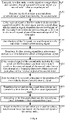
- FIG. 7 shows a flowchart of a phase compensation algorithm according to some embodiments of the present specification.
- S701 The received signal of the first radar is determined.
- S702 Whether the received signal of the first radar includes a second phase synchronization signal is determined, wherein if the received signal of the first radar includes the second phase synchronization signal, S703 is executed, and if the received signal of the first radar does not include the second phase synchronization signal, S707 is executed.
- the received signal S 10 of the first radar includes a first synchronization received signal is judged. If the S 10 does not include the first synchronization received signal, the S 10 is directly taken as a first echo processing signal. If the S 10 includes the first synchronization received signal, signal processing is performed on the S 10 .
- S703 Fourier transform is performed on the received signal of the first radar to obtain a first compressed signal.
- the first synchronization received signal in the received signal of the first radar is a point frequency signal
- Fourier transform is directly performed on the signal S 10 to obtain a first compressed signal S 11 , as shown in formula (1):
- S 11 ⁇ t S 10 wherein fft represents Fourier transform.
- the data of the peak phase of the S 11 at the position of a main lobe is zeroed to obtain a first zeroing signal S 12 .
- inverse Fourier transform is performed on the first zeroing signal so as to transform the first zeroing signal S 12 to a time domain, thereby obtaining a first echo processing signal S 13 , as shown in formula (2):
- S 13 i ⁇ t S 12 wherein ifft represents inverse Fourier transform.
- S712 Whether the received signal of the second radar includes a first phase synchronization signal is determined, wherein if the received signal of the second radar includes the first phase synchronization signal, S713 is executed, and if the received signal of the second radar does not include the first phase synchronization signal, S717 is executed.
- the received signal S 20 of the second radar includes a second synchronization received signal is judged. If the S 20 does not include the second synchronization received signal, the S 20 is directly taken as a second echo processing signal. If the S 20 includes the second synchronization received signal, signal transformation is performed on the S 20 .
- S713 Fourier transform is performed on the received signal of the second radar to obtain a second compressed signal.
- S715 The main lobe of the peak phase of the second compressed signal is zeroed to obtain a second zeroing signal.
- the data of the peak phase ⁇ 2 at the position of a main lobe is zeroed to obtain a second zeroing signal S 22 .
- a first compensation phase ⁇ 3 may be determined.
- imaging processing is performed on the target object by adopting the first echo processing signal S 13 and the third echo processing signal S 23 ' to obtain an imaging result of the target object.
- the first radar simultaneously transmits the radar signal and the first phase synchronization signal with the same carrier frequency
- the second radar transmits the second phase synchronization signal with the same carrier frequency to the first radar
- phase compensation is performed on the received signals of the first radar and the second radar according to the synchronization signals, thereby simplifying the design complexity of the radar system, reducing the phase error of the phase synchronization signals, and implementing phase synchronization of echo signals in the Bistatic SAR system.
- FIG. 8 shows a structural schematic diagram of a Bistatic SAR phase synchronization signal processing device based on carrier frequency signals according to some embodiments of the present specification.
- the device 800 includes a transmitting module 801, a receiving module 802 and a compensation module 803, wherein
- the transmitting module 801 includes:
- the compensation module 803 includes:
- the compensation module 803 further includes:
- the compensation module 803 further includes:
- the compensation sub-module includes:
- the compensation sub-module includes:
- Some embodiments of the present specification further provide Bistatic SAR phase synchronization signal processing equipment based on carrier frequency signals. All modules included in the equipment and all sub-modules and units included in the modules may be implemented by a processor in a terminal and may also be implemented by a specific logic circuit.
- the processor may be a Central Processing Unit (CPU), a Microprocessor (MPU), a Digital Signal Processor (DSP), or a Field Programmable Gate Array (FPGA).
- CPU Central Processing Unit
- MPU Microprocessor
- DSP Digital Signal Processor
- FPGA Field Programmable Gate Array
- FIG. 9 shows a schematic diagram of composition structures of the radar according to some embodiments of the present specification.
- the radar 900 at least includes a processor 901, a memory 902 and executable programs which are stored on the memory and can be executed by the processor, wherein the processor 901 may execute the executable programs, and the executable programs are configured to implement the Bistatic SAR phase synchronization signal processing method based on carrier frequency signals.
- some embodiments of the present specification provide a computer storage medium in which computer executable instructions are stored.
- the computer executable instructions are configured to execute the Bistatic SAR phase synchronization signal processing methods based on carrier frequency signals according to other embodiments in the present specification.
- the computer software product is stored in a storage medium (such as a Read Only Memory (ROM)/Random Access Memory (RAM), a magnetic disk, or an optical disk), and includes several instructions configured to enable a terminal device (such as a mobile phone, a computer, a server, or the like) to execute the method described in each embodiment of the present specification.
- a storage medium such as a Read Only Memory (ROM)/Random Access Memory (RAM), a magnetic disk, or an optical disk
- a terminal device such as a mobile phone, a computer, a server, or the like
- each flow and/or block in flow diagrams and/or block diagrams and a combination of flows and/or blocks in flow diagrams and/or block diagrams may be implemented by computer program instructions.
- These computer program instructions may be provided to a processor of a general-purpose computer, a special-purpose computer, an embedded processing machine or other programmable data processing terminals to generate a machine, so that the instructions executed by the processor of a computer or other programmable data processing terminals generate a device configured to implement the functions specified in one flow or multiple flows in flow diagrams and/or one block or multiple blocks in block diagrams.
- These computer program instructions may also be stored in a computer-readable memory that can guide a computer or other programmable data processing terminals to work in a specific mode, so that the instructions stored in the computer-readable memory generate a manufactured product including an instruction device, and the instruction device implements the functions specified in one flow or multiple flows in flow diagrams and/or one block or multiple blocks in block diagrams.
- These computer program instructions may also be loaded onto a computer or other programmable data processing terminals, so that a series of operation steps are performed on the computer or other programmable terminals to generate computer-implemented processing, and then, the instructions executed on the computer or other programmable terminals provide steps for implementing the functions specified in one flow or multiple flows in flow diagrams and/or one block or multiple blocks in block diagrams.
Landscapes
- Engineering & Computer Science (AREA)
- Remote Sensing (AREA)
- Radar, Positioning & Navigation (AREA)
- Physics & Mathematics (AREA)
- Computer Networks & Wireless Communication (AREA)
- General Physics & Mathematics (AREA)
- Electromagnetism (AREA)
- Radar Systems Or Details Thereof (AREA)
Description
- The disclosure relates to the technical field of radars, and particularly relates to a Bistatic Synthetic Aperture Radar (BiSAR) phase synchronization signal processing method and device.
- The SAR is an active microwave imaging radar which has the characteristics of all-time and all-weather work, and has unique advantages in applications, such as environmental protection, disaster monitoring, marine observation, resource exploration and military reconnaissance. A Bistatic SAR system is a novel radar system. Radars are mounted on two satellites flying in formation to form a bistatic radar system to together complete tasks such as high-resolution imaging of large surveying and mapping areas, ground elevation measurement, ocean current velocity measurement, ground moving target monitoring, and the like. The Bistatic SAR system is implemented by transmitting signals through a master satellite and simultaneously receiving the signals through a slave satellite. In related technologies, the working mode of the bistatic radar system is that after the master satellite transmits a radar signal, a synchronization signal is transmitted. Due to different time sequences of transmission of the two signals and different carrier frequencies, the design complexity of the radar system is increased, and the phase compensation accuracy is not high. Related technologies are known from
US2019/285742 A1 ,US2018/313951 A1 andCN110488285 A . - The invention is set out in the appended set of claims.
- The embodiments of the present specification provide a Bistatic SAR phase synchronization signal processing method and device. At the same time a first radar transmits a radar signal and a first phase synchronization signal with the same carrier frequency, thereby reducing the opening time of a signal receiving window, and simplifying the design complexity of a radar system. Furthermore, the first radar receives a second phase synchronization signal, which has a same carrier frequency as the first phase synchronization signal, transmitted by a second radar, and then, the phase synchronization signal and the radar signal received by the first radar and the second radar have the same carrier frequency, so that there is no need to perform scale transformation on the received phase synchronization signal and then perform phase compensation, and the phase compensation result is more accurate.
-
-
FIG. 1 is a flowchart of a Bistatic SAR phase synchronization signal processing method provided by some embodiments of the present specification. -
FIG. 2 is a schematic diagram of generation of a radar signal and a phase synchronization signal according to some embodiments of the present specification. -
FIG. 3 is another flowchart of implementation of a Bistatic SAR phase synchronization signal processing method according to some embodiments of the present specification. -
FIG. 4 is another flowchart of implementation of a Bistatic SAR phase synchronization signal processing method according to some embodiments of the present specification. -
FIG. 5 is another flowchart of implementation of a Bistatic SAR phase synchronization signal processing method based on carrier frequency signals according to some embodiments of the present specification. -
FIG. 6 is a time sequence diagram of transmitting and receiving signals by a first radar and a second radar according to some embodiments of the present specification. -
FIG. 7 is a flowchart of a phase compensation algorithm according to some embodiments of the present specification. -
FIG. 8 is a structural schematic diagram of a Bistatic SAR phase synchronization signal processing device according to some embodiments of the present specification. -
FIG. 9 is a schematic diagram of composition structures of the radar according to some embodiments of the present specification. - It should be understood that the specific embodiments described herein are merely configured to illustrate the present specification, but are not intended to limit the present specification.
- In the subsequent description, the use of suffixes, such as "modules", "components" or "units" for representing elements is only favorable for the description of the present specification, and has no specific meaning. Therefore, "modules", "components" or "units" may be used in a mixed manner.
- Some embodiments of the present specification provide a Bistatic SAR phase synchronization signal processing method based on carrier frequency signals.
FIG. 1 shows a flowchart of a Bistatic SAR phase synchronization signal processing method based on carrier frequency signals according to some embodiments of the present specification. As shown inFIG. 1 , the Bistatic SAR phase synchronization signal processing method based on carrier frequency signals includes the following operations: - S101: Transmitting, by a first radar a radar signal to a target object and a first phase synchronization signal to a second radar.
- Here, the carrier frequency of the radar signal is the same as that of the first phase synchronization signal. In a Bistatic SAR system, the first radar is a master satellite, and the second radar is a slave satellite. In a first time sequence of the first pulse repetition time, the first radar is responsible for transmitting a radar signal to a target object, and transmitting a first phase synchronization signal to the second radar in the same pulse period. In some embodiments, a plurality of second radars may be disposed in the Bistatic SAR system. In a second time sequence of the first pulse repetition time, the first radar receives an echo signal reflected by the radar signal, and the second radar receives the echo signal and the first phase synchronization signal.
- The radar signal and the first phase synchronization signal are the same carrier frequency signals which are transmitted by the first radar at the same time in two paths, wherein one path of the carrier frequency signal is mixed with a chirp signal to generate the radar signal, and the other path of the carrier frequency signal directly generates the first phase synchronization signal.
FIG. 2 shows a schematic diagram of generation of a radar signal and a phase synchronization signal a some embodiments of the present specification. As shown inFIG. 2 , 201 is a carrier frequency signal, 202 is a first phase synchronization signal directly generated by thecarrier frequency signal carrier frequency signal 201 and achirp signal 204. In the first pulse repetition time, the first radar receives and stores an echo signal reflected by the radar signal to obtain a received signal of the first radar; and the second radar receives and stores the echo signal and the first phase synchronization signal to obtain a received signal of the second radar. In some embodiments, the second radar may not receive the first phase synchronization signal, and the second radar only stores the echo signal to obtain a received signal of the second radar. - S102: A second phase synchronization signal transmitted by the second radar is received by the first radar.
- Here, the carrier frequency of the second phase synchronization signal is the same as the carrier frequency of the first phase synchronization signal. After the second radar receives the first phase synchronization signal transmitted by the first radar, in a first time sequence of the second pulse repetition time, the second radar transmits a second phase synchronization signal to the first radar, and the first radar transmits a radar signal to a target object. In a second time sequence of the second pulse repetition time, the first radar receives and stores an echo signal reflected by the radar signal and the second phase synchronization signal to obtain a received signal of the first radar; and the second radar receives and stores the echo signal reflected by the radar signal to obtain a received signal of the second radar. In some embodiments, the first radar may not receive the second phase synchronization signal, and the first radar only stores the echo signal to obtain a received signal of the first radar.
- S103: Phase synchronization compensation is performed on the received signal of the second radar at least according to the first phase synchronization signal and the second phase synchronization signal.
- Here, phase adjustment is performed on the received signal of the first radar and the received signal of the second radar, the received signal of the first radar at least including the second phase synchronization signal, and the received signal of the second radar at least including the first phase synchronization signal. Phase synchronization compensation is performed on the received signal of the second radar according to the compensation phase obtained by phase adjustment.
- In some embodiments, in different time sequences, phase compensation is performed on received signals of radars receiving phase synchronization signals. For example, in the first time sequence, the second radar receives a phase synchronization signal, and then, phase synchronization compensation is performed on the received signal of the second radar; and in the second time sequence, the first radar receives a phase synchronization signal, and then, phase synchronization compensation is performed on the received signal of the first radar.
- In the embodiments of the present specification, the first radar transmits a radar signal and a first phase synchronization signal with the same carrier frequency, thereby reducing the opening time of a signal receiving window, and simplifying the design complexity of a radar system. Furthermore, the first radar receives a second phase synchronization signal, which has a same carrier frequency as the first phase synchronization signal, transmitted by the second radar, and then, the phase synchronization signal and the radar signal received by the first radar and the second radar have the same carrier frequency, so that there is no need to perform scale transformation on the received phase synchronization signal and then perform phase compensation, and the phase compensation result is more accurate.
- Some embodiments of the present specification provide a Bistatic SAR phase synchronization signal processing method based on carrier frequency signals.
FIG. 3 shows another flowchart of implementation of a Bistatic SAR phase synchronization signal processing method based on carrier frequency signals according to some embodiments of the present specification. As shown inFIG. 3 , the Bistatic SAR phase synchronization signal processing method based on carrier frequency signals includes the following operations: - S301: The carrier frequency of the radar signal is determined.
- Here, the carrier frequency of the radar signal may be determined according to the parameters of the radar signal, wherein the carrier frequency of the radar signal is the same as the carrier frequency of the first phase synchronization signal and the carrier frequency of the second phase synchronization signal.
- S302: The pulse width of the first phase synchronization signal and the second phase synchronization signal are determined.
- Here, the pulse width is the pulse duration, and the unit is generally µs. If the distance between the first radar and the second radar is far, in order to increase the strength of the echo signal, a wider pulse width needs to be adopted. If the distance between the first radar and the second radar is close, a narrower pulse width may be adopted. Since the starting time of the second phase synchronization signal is between two adjacent times of transmitting radar signals, in order to ensure that both the first radar and the second radar can receive the phase synchronization signals transmitted by the other party, the pulse widths of the phase synchronization signals need to be determined according to the pulse repetition time, the free duration in each pulse repetition time, and the distance between the first radar and the second radar. In some embodiments, the pulse width of the first phase synchronization signal is the same as the pulse width of the second phase synchronization signal, in this way, during system design, the setting of transceivers of the phase synchronization signals may be simplified, thereby reducing the complexity of the system design.
- S303: According to the carrier frequency and the pulse width, transmitting, by the first radar the radar signal to the target object and the first phase synchronization signal to the second radar.
- Here, the first radar transmits, according to the pulse width of the first phase synchronization signal, the first phase synchronization signal to the second radar.
- The above S301 to S303 realize that " transmitting, by the first radar the radar signal to the target object and the first phase synchronization signal to the second radar ", the first radar may determine the pulse widths of transmitting the radar signal and the first phase synchronization signal according to the distance between the two radars, and then, the second radar may receive the signal transmitted by the first radar, so that phase synchronization compensation may be performed on the received signal of the radar.
- S304: A second phase synchronization signal transmitted by the second radar is received by the first radar.
- S305: Phase synchronization compensation is performed on the received signal of the second radar at least according to the first phase synchronization signal and the second phase synchronization signal.
- In the embodiments of the present specification, by determining the carrier frequency of the radar signal and the pulse widths of the phase synchronization signals, it can be ensured that the first radar and the second radar respectively receive the second phase synchronization signal and the first phase synchronization signal, so that phase synchronization compensation may be performed on the phase error generated during working of the two radars.
- Some embodiments of the present specification provide a Bistatic SAR phase synchronization signal processing method based on carrier frequency signals.
FIG. 4 shows another flowchart of implementation of a Bistatic SAR phase synchronization signal processing method based on carrier frequency signals according to the embodiment of the present specification. As shown inFIG. 4 , the Bistatic SAR phase synchronization signal processing method based on carrier frequency signals includes the following operations: - S401: Transmitting, by a first radar a radar signal to a target object and a first phase synchronization signal to a second radar.
- S402: A second phase synchronization signal transmitted by the second radar is received by the first radar.
- S403: If the received signal of the first radar includes an echo signal reflected by the radar signal and the second phase synchronization signal, the received signal of the first radar is transformed from a time domain to a frequency domain to obtain a first peak phase of the received signal of the first radar.
- Here, the received signal of the first radar and the received signal of the second radar are signals obtained through one transmission and reception respectively, and in transmitting and receiving processes, there is a phase error respectively, so it may be needed to perform phase compensation on the received signal of the second radar. When the received signal of the first radar includes an echo signal reflected by the radar signal and the second phase synchronization signal, since the received signal of the first radar is a point frequency signal, Fourier transform may be performed on the received signal of the first radar so as to transform the received signal of the first radar from a time domain to a frequency domain to obtain a first compressed signal, and then, a peak phase of the first compressed signal is extracted.
- S404: The data of the first peak phase at the position of a main lobe is zeroed to obtain a first zeroing signal.
- Here, before compensation for the phase, in order to eliminate the influence of the introduced synchronization signal on an imaging operation, it may be needed to perform a zeroing operation on the data at the position of the main lobe of the peak of the signal after Fourier transform.
- S405: The first zeroing signal is transformed from a frequency domain to a time domain to obtain a first processed signal.
- Here, inverse Fourier transform is performed on the first zeroing signal so as to transform the first zeroing signal from a frequency domain to a time domain to obtain a first processed signal.
- Thus, transformation between a time domain and a frequency domain is performed on the received signal of the first radar to convert a complicated received signal into a signal easy to process, so as to improve the efficiency of phase compensation.
- S406: If the received signal of the second radar includes the echo signal and the first phase synchronization signal, the received signal of the second radar is transformed from a time domain to a frequency domain to obtain a second peak phase of the received signal of the second radar.
- Here, when the received signal of the second radar includes the echo signal reflected by the radar signal and the first phase synchronization signal, Fourier transform is performed on the received signal of the second radar so as to transform the received signal of the second radar from a time domain to a frequency domain to obtain a second compressed signal, and then, a peak phase of the second compressed signal is extracted.
- S407: The data of the second peak phase at the position of a main lobe is zeroed to obtain a second zeroing signal.
- Here, before compensation for the phase, in order to eliminate the influence of the introduced synchronization signal on an imaging operation, it may be needed to perform a zeroing operation on the data at the position of the main lobe of the peak of the signal after Fourier transform.
- S408: The second zeroing signal is transformed from a frequency domain to a time domain to obtain a second processed signal.
- Here, inverse Fourier transform is performed on the second zeroing signal so as to transform the second zeroing signal from a frequency domain to a time domain to obtain a second processed signal.
- Thus, transformation between a time domain and a frequency domain is performed on the received signal of the second radar to convert a complicated received signal into a signal easy to process, so as to improve the efficiency of phase compensation of the received signal.
- S409: According to the first peak phase and the second peak phase, a first compensation phase is determined.
- Here, the difference of peak phases, namely the peak phase difference, between the first peak phase and the second peak phase is determined, and 1/2 of the peak phase difference is determined as a first compensation phase.
- S410: Based on the first compensation phase, phase synchronization compensation is performed on the received signal of the second radar.
- Here, in the Bistatic SAR system, the first radar as a master satellite is responsible for transmitting radar signals, the second radar as a slave satellite does not transmit radar signals, and the second radar transmits phase synchronization signals, so that phase synchronization compensation may be performed on the received signal of the second radar according to the compensation phase.
- In some achievable embodiments, phase synchronization compensation may also be performed on the received signal of the second radar in the following mode.
- Operation 1: Interpolation is performed on the first compensation phase to obtain a second compensation phase.
- Here, interpolation is performed on the obtained first compensation phase, wherein the number of interpolation points is determined by the number of azimuth points of the second processed signal, and a second compensation phase is obtained.
- Operation 2: Based on the second compensation phase, phase adjustment is performed on the second processed signal to implement phase synchronization compensation on the second processed signal.
- Here, the second compensation phase and function corresponding to the second processed signal are multiplied to perform phase adjustment on the second processed signal, thereby implementing phase synchronization compensation on the second processed signal.
- Thus, transformation between a time domain and a frequency domain is performed on the received signal of the radar to convert the original received signal into a signal easy to process, so as to improve the efficiency of phase compensation and improve the accuracy of phase compensation.
- In some embodiments of the present specification, by performing signal processing on the received signal of the first radar and the received signal of the second radar, including the phase synchronization signals, the phase errors of the phase synchronization signals may be reduced, and phase synchronization of echo signals in the Bistatic SAR system may be implemented.
- In some embodiments, after S410, the method further includes the following processes:
- a third processed signal obtained by performing phase synchronization compensation on the second processed signal is determined; and based on the first processed signal and the third processed signal, imaging processing is performed on the target object to obtain an imaging result.
- Here, according to the third processed signal obtained by performing phase synchronization compensation on the second processed signal and the first processed signal after compressing and zeroing, imaging processing is performed on the target object, and an imaging result of the target object may be obtained.
- Some embodiments of the present specification provide a Bistatic SAR phase synchronization signal processing method based on carrier frequency signals, applied to a Bistaitc SAR system. The Bistatic SAR phase synchronization signal processing method based on carrier frequency signals is implemented through the following operations:
- Here, the first radar (master satellite) is responsible for transmitting a radar signal to a target object, and the first radar (master satellite) and the second radar (slave satellite) simultaneously receive echo signals and mutually transmit and receive phase synchronization signals of the other party.
FIG. 5 shows another flowchart of implementation of a Bistatic SAR phase synchronization signal processing method based on carrier frequency signals according to some embodiments of the present specification. With reference toFIG. 5 , the Bistatic SAR phase synchronization signal processing method based on carrier frequency signals is described as follows: - S501: The pulse width of the first phase synchronization signal and the second phase synchronization signal are determined.
- Here, the pulse width of the first phase synchronization signal is the same as the pulse width of the second phase synchronization signal.
- S502: The first radar is controlled to transmit the first phase synchronization signal to the second radar according to the pulse width of the first phase synchronization signal, and simultaneously, a radar signal is transmitted, by the first radar, to the target object.
- Here, during the first pulse repetition time (PRT), the Bistatic SAR system controls the first radar to transmit the first radar signal to the target object, and simultaneously controls the first radar to transmit the first phase synchronization signal to the second radar.
- S503: A first received signal of the first radar is determined.
- Here, the first radar receives an echo signal to obtain a first echo received signal to form a first received signal.
- S504: A second received signal of the second radar is determined.
- Here, the second radar receives an echo signal to obtain a second echo received signal and simultaneously receives a first phase synchronization signal, and the first phase synchronization signal and the second echo received signal form a second received signal. The execution order of S503 and S504 may not be sequential.
- S505: The second radar is controlled to transmit the second phase synchronization signal to the first radar according to the pulse width of the second phase synchronization signal, and simultaneously, a radar signal is transmitted, by the first radar, to the target object.
- Here, during the second pulse repetition time (PRT2), the Bistatic SAR system controls the first radar to transmit the second radar signal to the target object, and simultaneously controls the second radar to transmit the second phase synchronization signal to the first radar.
- S506: A third received signal of the first radar is determined.
- Here, during the second PRT, the first radar receives an echo signal reflected by the second radar signal to obtain a third echo received signal and simultaneously receives a second phase synchronization signal, and the third echo received signal and the second phase synchronization signal together form a third received signal of the first radar.
- S507: A fourth received signal of the second radar is determined.
- Here, during the second PRT, the second radar receives an echo signal reflected by the second radar signal to obtain a fourth echo received signal to form a fourth received signal.
- In some embodiments, the first received signal and the third received signal of the first radar form the received signal of the first radar, and the second received signal and the fourth received signal of the second radar form the received signal of the second radar.
- S508: According to the second phase synchronization signal received by the first radar and the first phase synchronization signal received by the second radar, peak phases of respective phase synchronization signals are determined so as to determine a compensation phase.
- S509: According to the compensation phase, phase synchronization compensation is performed on the received signal of the second radar.
- Corresponding to the above operations of signal transmission and reception, some embodiments of the present specification provide a corresponding time sequence diagram of transmitting and receiving signals by a first radar and a second radar.
FIG. 6 shows a time sequence diagram of transmitting and receiving signals by a first radar and a second radar according to some embodiments of the present specification. With reference toFIG. 6 , 601 means that during the PRT1, a first radar 61 transmits a radar signal and a first phase synchronization signal (corresponding to S502); 602 means that the first radar 61 receives an echo signal reflected by the radar signal (corresponding to S503); 603 means that a second radar 62 receives the echo signal and the first phase synchronization signal (corresponding to S504); 604 means that during the PRT2, the second radar 62 transmits a second phase synchronization signal to the first radar 61, and the first radar 61 transmits a radar signal (corresponding to S505); 605 means that the first radar 61 receives the second phase synchronization signal and the echo signal (corresponding to S506); and 606 means that the second radar 62 receives the echo signal (corresponding to S507). - In a specific example, both the first radar (master satellite) and the second radar (slave satellite) have a sampling rate of 60MHz and a carrier frequency of 1.2GHz. The radar signal transmitted by the first radar is a chirp of negative frequency modulation with a pulse width of 40µs and a band width of 50MHz, the first phase synchronization signal transmitted by the first radar is a sinusoidal signal with a frequency of 1.2GHz, and the second phase synchronization signal transmitted by the second radar is a sinusoidal signal with a frequency of 1.2GHz. This example will be described with the contents of the embodiments of the present specification below.
- (1) Operation 1: A first radar and a second radar transmit and receive signals.
- Assuming that there is a point target in a scene and its backscattering coefficient is set to 1, one or more echo signals of the point target are received by a first radar and a second radar to obtain a first echo signal and a second echo signal. The first radar transmits a first phase synchronization signal, and the second radar receives the first phase synchronization signal transmitted by the first radar to obtain a second synchronization received signal; and the second radar transmits a second phase synchronization signal, and the first radar receives the second phase synchronization signal transmitted by the second radar to obtain a first synchronization received signal. The time sequence diagram of signal transmission and reception of the SAR system is as shown in
FIG. 6 . - The first radar simultaneously stores the first echo received signal and the first synchronization received signal to obtain a received signal S 10 of the first radar; and the second radar simultaneously stores the second echo received signal and the second synchronization received signal to obtain a received signal S 20 of the second radar.
- (2) Operation 2: Phase synchronization compensation is performed on the received signal of the second radar.
- Some embodiments of the present specification provide a flowchart of a phase compensation algorithm.
FIG. 7 shows a flowchart of a phase compensation algorithm according to some embodiments of the present specification. With reference toFIG. 7 : - S701: The received signal of the first radar is determined.
- S702: Whether the received signal of the first radar includes a second phase synchronization signal is determined, wherein if the received signal of the first radar includes the second phase synchronization signal, S703 is executed, and if the received signal of the first radar does not include the second phase synchronization signal, S707 is executed.
- Here, according to the time sequence relationship of the pulse repetition time, whether the received signal S 10 of the first radar includes a first synchronization received signal is judged. If the S 10 does not include the first synchronization received signal, the S 10 is directly taken as a first echo processing signal. If the S 10 includes the first synchronization received signal, signal processing is performed on the S 10.
- S703: Fourier transform is performed on the received signal of the first radar to obtain a first compressed signal.
- Here, because the first synchronization received signal in the received signal of the first radar is a point frequency signal, Fourier transform is directly performed on the signal S 10 to obtain a first compressed signal S 11, as shown in formula (1):

wherein fft represents Fourier transform. - S704: A first peak phase of the first compressed signal is extracted.
- Here, a peak phase ϕ 1 of the first compressed signal S 11 is extracted.
- S705: The main lobe of the peak phase of the first compressed signal is zeroed to obtain a first zeroing signal.
- Here, the data of the peak phase of the S 11 at the position of a main lobe is zeroed to obtain a first zeroing signal S 12.
- S706: Inverse Fourier transform is performed on the first zeroing signal.
- Here, inverse Fourier transform is performed on the first zeroing signal so as to transform the first zeroing signal S 12 to a time domain, thereby obtaining a first echo processing signal S 13, as shown in formula (2):

wherein ifft represents inverse Fourier transform. - S707: A first echo processing signal is determined.
- S711: A received signal of the second radar is determined.
- S712: Whether the received signal of the second radar includes a first phase synchronization signal is determined, wherein if the received signal of the second radar includes the first phase synchronization signal, S713 is executed, and if the received signal of the second radar does not include the first phase synchronization signal, S717 is executed.
- Here, according to the time sequence relationship of the pulse repetition time, whether the received signal S 20 of the second radar includes a second synchronization received signal is judged. If the S 20 does not include the second synchronization received signal, the S 20 is directly taken as a second echo processing signal. If the S 20 includes the second synchronization received signal, signal transformation is performed on the S 20.
- S713: Fourier transform is performed on the received signal of the second radar to obtain a second compressed signal.
- Here, because the second synchronization received signal in the received signal of the second radar is a point frequency signal, Fourier transform may be directly performed on the signal S 20 to obtain a second compressed signal S 21, as shown in formula (3):

- S714: A second peak phase of the second compressed signal is extracted.
- Here, a peak phase ϕ 2 of the second compressed signal S 21 is extracted.
- S715: The main lobe of the peak phase of the second compressed signal is zeroed to obtain a second zeroing signal.
- Here, the data of the peak phase ϕ 2 at the position of a main lobe is zeroed to obtain a second zeroing signal S 22.
- S716: Inverse Fourier transform is performed on the second zeroing signal.
- Here, inverse Fourier transform is performed on the second zeroing signal so as to transform the second zeroing signal S 22 to a time domain, thereby obtaining a second echo processing signal S 23, as shown in formula (4):

- S717: A second echo processing signal is determined.
- S718: A first compensation phase is determined.
- Here, based on the first peak phase and the second peak phase, a first compensation phase ϕ 3 may be determined. The specific formula of the first compensation phase ϕ 3 is as shown in formula (5):

- S719: Interpolation is performed on the first compensation phase.
- Interpolation is performed on the first compensation phase ϕ 3 to obtain a second compensation phase


- After the above operations, imaging processing is performed on the target object by adopting the first echo processing signal S 13 and the third echo processing signal S 23' to obtain an imaging result of the target object.
- In some embodiments of the present specification, the first radar simultaneously transmits the radar signal and the first phase synchronization signal with the same carrier frequency, the second radar transmits the second phase synchronization signal with the same carrier frequency to the first radar, and phase compensation is performed on the received signals of the first radar and the second radar according to the synchronization signals, thereby simplifying the design complexity of the radar system, reducing the phase error of the phase synchronization signals, and implementing phase synchronization of echo signals in the Bistatic SAR system.
- Some embodiments of the present specification provides a Bistatic SAR phase synchronization signal processing device based on carrier frequency signals.
FIG. 8 shows a structural schematic diagram of a Bistatic SAR phase synchronization signal processing device based on carrier frequency signals according to some embodiments of the present specification. As shown inFIG. 8 , the device 800 includes a transmitting module 801, a receiving module 802 and a compensation module 803, wherein - the transmitting module 801 is configured to transmit, by a first radar a radar signal to a target object and a first phase synchronization signal to a second radar, wherein the carrier frequency of the radar signal is the same as the carrier frequency of the first phase synchronization signal;
- the receiving module 802 is configured to receive, by the first radar, a second phase synchronization signal transmitted by the second radar; and
- the compensation module 803 is configured to perform phase synchronization compensation on the received signal of the second radar at least according to the first phase synchronization signal and the second phase synchronization signal.
- In the above device, the transmitting module 801 includes:
- a first determining sub-module configured to determine the carrier frequency of the radar signal;
- a second determining sub-module configured to determine the pulse width of the first phase synchronization signal and the second phase synchronization signal; and
- a first transmitting sub-module configured to transmit, by the first radar, the radar signal to the target object according to the carrier frequency and the pulse width, and transmit the first phase synchronization signal to the second radar.
- In the above device, the compensation module 803 includes:
- a first transformation sub-module configured to transform the received signal of the first radar from a time domain to a frequency domain to obtain a first peak phase of the received signal of the first radar if the received signal of the first radar includes the echo signal reflected by the radar signal and the second phase synchronization signal;
- a second transformation sub-module configured to transform the received signal of the second radar from a time domain to a frequency domain to obtain a second peak phase of the received signal of the second radar if the received signal of the second radar includes the echo signal and the first phase synchronization signal;
- a third determining sub-module configured to determine a first compensation phase according to the first peak phase and the second peak phase; and
- a compensation sub-module configured to perform phase synchronization compensation on the received signal of the second radar based on the first compensation phase.
- In the above device, the compensation module 803 further includes:
- a first zeroing sub-module configured to zero the data of the first peak phase at the position of a main lobe to obtain a first zeroing signal; and
- a third transformation sub-module configured to transform the first zeroing signal from a frequency domain to a time domain to obtain a first processed signal.
- In the above device, the compensation module 803 further includes:
- a second zeroing sub-module configured to zero the data of the second peak phase at the position of a main lobe to obtain a second zeroing signal; and
- a fourth transformation sub-module configured to transform the second zeroing signal from a frequency domain to a time domain to obtain a second processed signal.
- In the above device, the compensation sub-module includes:
- an interpolation unit configured to perform interpolation on the first compensation phase to obtain a second compensation phase; and
- a phase adjustment unit configured to perform phase adjustment on the second processed signal based on the second compensation phase to implement phase synchronization compensation on the second processed signal.
- In the above device, the compensation sub-module includes:
- a determining unit configured to determine a third processed signal obtained by performing phase synchronization compensation on the second processed signal; and
- an imaging processing unit configured to perform imaging processing on the target object based on the first processed signal and the third processed signal to obtain an imaging result.
- Some embodiments of the present specification further provide Bistatic SAR phase synchronization signal processing equipment based on carrier frequency signals. All modules included in the equipment and all sub-modules and units included in the modules may be implemented by a processor in a terminal and may also be implemented by a specific logic circuit. In implementation processes, the processor may be a Central Processing Unit (CPU), a Microprocessor (MPU), a Digital Signal Processor (DSP), or a Field Programmable Gate Array (FPGA).
- Some embodiments of the present specification provide a radar.
FIG. 9 shows a schematic diagram of composition structures of the radar according to some embodiments of the present specification. As shown inFIG. 9 , the radar 900 at least includes a processor 901, a memory 902 and executable programs which are stored on the memory and can be executed by the processor, wherein
the processor 901 may execute the executable programs, and the executable programs are configured to implement the Bistatic SAR phase synchronization signal processing method based on carrier frequency signals. - Correspondingly, some embodiments of the present specification provide a computer storage medium in which computer executable instructions are stored. The computer executable instructions are configured to execute the Bistatic SAR phase synchronization signal processing methods based on carrier frequency signals according to other embodiments in the present specification.
- It should be noted that in the disclosure, the terms "include", "contain" or any other variants thereof are intended to cover non-exclusive inclusions, so that a process, method, article or device including a series of elements includes not only those elements, but also other elements that are not explicitly listed, or further includes elements inherent to such process, method, article or device. Without more restrictions, the element defined by the sentence "include one ..." does not exclude that there are other identical elements in the process, method, article or device including the element.
- The serial numbers of the above embodiments of the present specification are merely for description, and do not represent the superiority or inferiority of the embodiments.
- Through the description of the above embodiments, those skilled in the art can clearly understand that the methods in the above embodiments may be implemented by means of software and a necessary general hardware platform, and may also be implemented by hardware. However, in many cases, the former is the better embodiment. Based on this understanding, the technical solution of the present specification or a part that contributes to the existing technology may be embodied in a form of software products. The computer software product is stored in a storage medium (such as a Read Only Memory (ROM)/Random Access Memory (RAM), a magnetic disk, or an optical disk), and includes several instructions configured to enable a terminal device (such as a mobile phone, a computer, a server, or the like) to execute the method described in each embodiment of the present specification.
- The present specification is described with reference to flow diagrams and/or block diagrams of methods, terminals (systems) and computer program products according to the embodiments of the present specification. It should be understood that each flow and/or block in flow diagrams and/or block diagrams and a combination of flows and/or blocks in flow diagrams and/or block diagrams may be implemented by computer program instructions. These computer program instructions may be provided to a processor of a general-purpose computer, a special-purpose computer, an embedded processing machine or other programmable data processing terminals to generate a machine, so that the instructions executed by the processor of a computer or other programmable data processing terminals generate a device configured to implement the functions specified in one flow or multiple flows in flow diagrams and/or one block or multiple blocks in block diagrams.
- These computer program instructions may also be stored in a computer-readable memory that can guide a computer or other programmable data processing terminals to work in a specific mode, so that the instructions stored in the computer-readable memory generate a manufactured product including an instruction device, and the instruction device implements the functions specified in one flow or multiple flows in flow diagrams and/or one block or multiple blocks in block diagrams.
- These computer program instructions may also be loaded onto a computer or other programmable data processing terminals, so that a series of operation steps are performed on the computer or other programmable terminals to generate computer-implemented processing, and then, the instructions executed on the computer or other programmable terminals provide steps for implementing the functions specified in one flow or multiple flows in flow diagrams and/or one block or multiple blocks in block diagrams.
- The above embodiments are only the exemplary embodiments of the present specification, and do not limit the claims of the present specification.
Claims (2)
- A Bistatic Synthetic Aperture Radar, SAR, phase synchronization signal processing method, comprising:transmitting, by a first radar at a same time, a radar signal to a target object and a first phase synchronization signal to a second radar, wherein a carrier frequency of the radar signal is the same as that of the first phase synchronization signal;receiving, by the first radar, a second phase synchronization signal transmitted by the second radar (S102); andperforming, at least according to the first phase synchronization signal and the second phase synchronization signal, phase synchronization compensation on the received signal of the second radar (S103),wherein the performing, at least according to the first phase synchronization signal and the second phase synchronization signal, phase synchronization compensation on the received signal of the second radar (S103) comprises:performing phase adjustment on a received signal of the first radar and the received signal of the second radar, wherein the received signal of the first radar at least comprises the second phase synchronization signal, and the received signal of the second radar at least comprises the first phase synchronization signal; andperforming, according to a compensation phase obtained by phase adjustment, phase synchronization compensation on the received signal of the second radar.
- The method of claim 1, wherein the transmitting, by a first radar at the same time, a radar signal to a target object and a first phase synchronization signal to a second radar comprises:determining the carrier frequency of the radar signal (S301);determining pulse width of the first phase synchronization signal and the second phase synchronization signal (S302); andtransmitting, by the first radar at the same time, according to the carrier frequency and the pulse width, the radar signal to the target object and the first phase synchronization signal to the second radar.
Applications Claiming Priority (1)
| Application Number | Priority Date | Filing Date | Title |
|---|---|---|---|
| CN202010089336.5A CN111257876A (en) | 2020-02-12 | 2020-02-12 | Dual-base SAR phase synchronization signal processing method and device based on carrier frequency signal |
Publications (2)
| Publication Number | Publication Date |
|---|---|
| EP3865908A1 EP3865908A1 (en) | 2021-08-18 |
| EP3865908B1 true EP3865908B1 (en) | 2022-12-28 |
Family
ID=70918197
Family Applications (1)
| Application Number | Title | Priority Date | Filing Date |
|---|---|---|---|
| EP20176890.0A Active EP3865908B1 (en) | 2020-02-12 | 2020-05-27 | Bistatic sar phase synchronization signal processing method and device |
Country Status (2)
| Country | Link |
|---|---|
| EP (1) | EP3865908B1 (en) |
| CN (1) | CN111257876A (en) |
Families Citing this family (6)
| Publication number | Priority date | Publication date | Assignee | Title |
|---|---|---|---|---|
| CN112505697B (en) * | 2020-11-13 | 2023-05-09 | 中国科学院空天信息创新研究院 | A time and frequency synchronization method, receiving device and dual multi-radio radar system |
| CN113466858B (en) * | 2021-06-02 | 2023-09-08 | 中国科学院空天信息创新研究院 | An information processing method, device and storage medium |
| CN115308740B (en) * | 2022-05-13 | 2025-08-19 | 北京理工大学 | Multi-station synchronization method for distributed synthetic aperture radar |
| CN121941941A (en) * | 2023-09-25 | 2026-04-28 | 华为技术有限公司 | Method, apparatus and system for imaging |
| CN119335518B (en) * | 2024-10-23 | 2025-12-05 | 电子科技大学 | A Time Synchronization Method for Multi-Send and Multi-Receive Radar Based on Direct Wave and Differential GPS Ranging |
| CN119667675B (en) * | 2024-11-25 | 2026-01-13 | 上海卫星工程研究所 | Spaceborne Bistatic SAR Imaging System and Method |
Family Cites Families (9)
| Publication number | Priority date | Publication date | Assignee | Title |
|---|---|---|---|---|
| DE10256420B4 (en) * | 2002-12-02 | 2005-10-20 | Deutsch Zentr Luft & Raumfahrt | Method and apparatus for compensating phase errors of a bi- or multistatic synthetic aperture radar system |
| DE10348621B4 (en) * | 2003-10-15 | 2013-10-10 | Astrium Gmbh | Method for radar measurements using reference radar signals |
| CN104459694A (en) * | 2014-12-04 | 2015-03-25 | 北京航空航天大学 | GEO SAR high-resolution imaging method based on high-order slant range model |
| CN106019278B (en) * | 2016-05-09 | 2018-06-15 | 中国人民解放军国防科学技术大学 | A kind of FMCW SAR phase synchronization methods based on distributed satellites |
| CN107422323B (en) * | 2017-04-27 | 2019-12-10 | 中国科学院电子学研究所 | Bistatic SAR non-interrupted phase synchronization method and its device and equipment |
| CN108833071B (en) * | 2018-03-19 | 2020-11-10 | 中国科学院电子学研究所 | A phase synchronization method and device |
| CN109738893B (en) * | 2019-01-24 | 2020-11-03 | 中国科学院电子学研究所 | Method and device for generating echo data of dual-base synthetic aperture radar |
| CN109917388B (en) * | 2019-04-08 | 2020-04-07 | 中国科学院电子学研究所 | Double-base synthetic aperture radar phase synchronization method, device, equipment and storage medium |
| CN110488285B (en) * | 2019-07-29 | 2020-10-02 | 中国科学院电子学研究所 | Non-interrupt bistatic SAR (synthetic aperture radar) phase synchronization signal processing method based on coding signal |
-
2020
- 2020-02-12 CN CN202010089336.5A patent/CN111257876A/en active Pending
- 2020-05-27 EP EP20176890.0A patent/EP3865908B1/en active Active
Also Published As
| Publication number | Publication date |
|---|---|
| EP3865908A1 (en) | 2021-08-18 |
| CN111257876A (en) | 2020-06-09 |
Similar Documents
| Publication | Publication Date | Title |
|---|---|---|
| EP3865908A1 (en) | Bistatic sar phase synchronization signal processing method and device | |
| US10830869B2 (en) | Vehicle radar system and method of calibrating the same | |
| EP3124994B1 (en) | Vehicle radar device | |
| EP3821268B1 (en) | Localization method for locating at least one object using wave-based signals and localization system | |
| US9910150B2 (en) | Method, antenna array, radar system and vehicle | |
| EP3407082B1 (en) | Apparatus and method for determining a distance to an object | |
| US12153125B2 (en) | Radar system and method for performing direction of arrival estimation in a radar system | |
| US20110267223A1 (en) | System and Method for Resolving Ambiguity in Radar, Lidar, and Acoustic Systems | |
| US10209347B2 (en) | Radar test systems and methods | |
| EP3561539A1 (en) | Angular resolution of targets using separate radar receivers | |
| EP3982148A1 (en) | Radar target simulator with continuous distance emulation and corresponding simulation method | |
| US12146981B2 (en) | Resolving doppler unambiguity in TDM-MIMO radars based on spatial phase change rate | |
| US12099110B2 (en) | Radar system and method for performing direction of arrival estimation | |
| EP3059609B1 (en) | Radar apparatus | |
| CN114994678B (en) | Multi-channel bistatic SAR wireless phase predistortion method, device and electronic equipment | |
| EP4394430A1 (en) | Joint communication and sensing system and signalling for user equipment sensing | |
| US20240019565A1 (en) | Motion compensation for fast target detection in automotive radar | |
| EP3767331B1 (en) | Information measurement method and information measurement device | |
| WO2023210451A1 (en) | Positioning system, vehicle provided with same, and positioning method | |
| CN109738893B (en) | Method and device for generating echo data of dual-base synthetic aperture radar | |
| EP4137839A1 (en) | Low level radar fusion for automotive radar transceivers | |
| CN118884370B (en) | Interference signal generation method, method for interfering with synthetic aperture radar, and jammer | |
| US12455306B2 (en) | Spectrum analysis program, signal processing device, radar device, communication terminal, fixed communication device, and recording medium | |
| EP4202473A1 (en) | Radar sensor processing chain | |
| Haider et al. | Automotive radar sensor behavioral models for closed loop simulations |
Legal Events
| Date | Code | Title | Description |
|---|---|---|---|
| PUAI | Public reference made under article 153(3) epc to a published international application that has entered the european phase |
Free format text: ORIGINAL CODE: 0009012 |
|
| STAA | Information on the status of an ep patent application or granted ep patent |
Free format text: STATUS: REQUEST FOR EXAMINATION WAS MADE |
|
| 17P | Request for examination filed |
Effective date: 20200527 |
|
| AK | Designated contracting states |
Kind code of ref document: A1 Designated state(s): AL AT BE BG CH CY CZ DE DK EE ES FI FR GB GR HR HU IE IS IT LI LT LU LV MC MK MT NL NO PL PT RO RS SE SI SK SM TR |
|
| RBV | Designated contracting states (corrected) |
Designated state(s): AL AT BE BG CH CY CZ DE DK EE ES FI FR GB GR HR HU IE IS IT LI LT LU LV MC MK MT NL NO PL PT RO RS SE SI SK SM TR |
|
| STAA | Information on the status of an ep patent application or granted ep patent |
Free format text: STATUS: EXAMINATION IS IN PROGRESS |
|
| 17Q | First examination report despatched |
Effective date: 20211115 |
|
| GRAP | Despatch of communication of intention to grant a patent |
Free format text: ORIGINAL CODE: EPIDOSNIGR1 |
|
| STAA | Information on the status of an ep patent application or granted ep patent |
Free format text: STATUS: GRANT OF PATENT IS INTENDED |
|
| INTG | Intention to grant announced |
Effective date: 20220729 |
|
| RIN1 | Information on inventor provided before grant (corrected) |
Inventor name: DENG, YUNKAI Inventor name: LIU, DACHENG Inventor name: CHEN, YAFENG Inventor name: LIU, KAIYU Inventor name: ZHANG, HENG Inventor name: LIANG, DA Inventor name: LIN, HAOYU Inventor name: WANG, YU |
|
| GRAS | Grant fee paid |
Free format text: ORIGINAL CODE: EPIDOSNIGR3 |
|
| GRAA | (expected) grant |
Free format text: ORIGINAL CODE: 0009210 |
|
| STAA | Information on the status of an ep patent application or granted ep patent |
Free format text: STATUS: THE PATENT HAS BEEN GRANTED |
|
| AK | Designated contracting states |
Kind code of ref document: B1 Designated state(s): AL AT BE BG CH CY CZ DE DK EE ES FI FR GB GR HR HU IE IS IT LI LT LU LV MC MK MT NL NO PL PT RO RS SE SI SK SM TR |
|
| REG | Reference to a national code |
Ref country code: GB Ref legal event code: FG4D |
|
| REG | Reference to a national code |
Ref country code: CH Ref legal event code: EP |
|
| REG | Reference to a national code |
Ref country code: DE Ref legal event code: R096 Ref document number: 602020007157 Country of ref document: DE |
|
| REG | Reference to a national code |
Ref country code: AT Ref legal event code: REF Ref document number: 1540828 Country of ref document: AT Kind code of ref document: T Effective date: 20230115 |
|
| REG | Reference to a national code |
Ref country code: IE Ref legal event code: FG4D |
|
| REG | Reference to a national code |
Ref country code: LT Ref legal event code: MG9D |
|
| PG25 | Lapsed in a contracting state [announced via postgrant information from national office to epo] |
Ref country code: SE Free format text: LAPSE BECAUSE OF FAILURE TO SUBMIT A TRANSLATION OF THE DESCRIPTION OR TO PAY THE FEE WITHIN THE PRESCRIBED TIME-LIMIT Effective date: 20221228 Ref country code: NO Free format text: LAPSE BECAUSE OF FAILURE TO SUBMIT A TRANSLATION OF THE DESCRIPTION OR TO PAY THE FEE WITHIN THE PRESCRIBED TIME-LIMIT Effective date: 20230328 Ref country code: LT Free format text: LAPSE BECAUSE OF FAILURE TO SUBMIT A TRANSLATION OF THE DESCRIPTION OR TO PAY THE FEE WITHIN THE PRESCRIBED TIME-LIMIT Effective date: 20221228 Ref country code: FI Free format text: LAPSE BECAUSE OF FAILURE TO SUBMIT A TRANSLATION OF THE DESCRIPTION OR TO PAY THE FEE WITHIN THE PRESCRIBED TIME-LIMIT Effective date: 20221228 |
|
| REG | Reference to a national code |
Ref country code: NL Ref legal event code: MP Effective date: 20221228 |
|
| REG | Reference to a national code |
Ref country code: AT Ref legal event code: MK05 Ref document number: 1540828 Country of ref document: AT Kind code of ref document: T Effective date: 20221228 |
|
| PG25 | Lapsed in a contracting state [announced via postgrant information from national office to epo] |
Ref country code: RS Free format text: LAPSE BECAUSE OF FAILURE TO SUBMIT A TRANSLATION OF THE DESCRIPTION OR TO PAY THE FEE WITHIN THE PRESCRIBED TIME-LIMIT Effective date: 20221228 Ref country code: LV Free format text: LAPSE BECAUSE OF FAILURE TO SUBMIT A TRANSLATION OF THE DESCRIPTION OR TO PAY THE FEE WITHIN THE PRESCRIBED TIME-LIMIT Effective date: 20221228 Ref country code: HR Free format text: LAPSE BECAUSE OF FAILURE TO SUBMIT A TRANSLATION OF THE DESCRIPTION OR TO PAY THE FEE WITHIN THE PRESCRIBED TIME-LIMIT Effective date: 20221228 Ref country code: GR Free format text: LAPSE BECAUSE OF FAILURE TO SUBMIT A TRANSLATION OF THE DESCRIPTION OR TO PAY THE FEE WITHIN THE PRESCRIBED TIME-LIMIT Effective date: 20230329 |
|
| PG25 | Lapsed in a contracting state [announced via postgrant information from national office to epo] |
Ref country code: NL Free format text: LAPSE BECAUSE OF FAILURE TO SUBMIT A TRANSLATION OF THE DESCRIPTION OR TO PAY THE FEE WITHIN THE PRESCRIBED TIME-LIMIT Effective date: 20221228 |
|
| PG25 | Lapsed in a contracting state [announced via postgrant information from national office to epo] |
Ref country code: SM Free format text: LAPSE BECAUSE OF FAILURE TO SUBMIT A TRANSLATION OF THE DESCRIPTION OR TO PAY THE FEE WITHIN THE PRESCRIBED TIME-LIMIT Effective date: 20221228 Ref country code: RO Free format text: LAPSE BECAUSE OF FAILURE TO SUBMIT A TRANSLATION OF THE DESCRIPTION OR TO PAY THE FEE WITHIN THE PRESCRIBED TIME-LIMIT Effective date: 20221228 Ref country code: PT Free format text: LAPSE BECAUSE OF FAILURE TO SUBMIT A TRANSLATION OF THE DESCRIPTION OR TO PAY THE FEE WITHIN THE PRESCRIBED TIME-LIMIT Effective date: 20230428 Ref country code: ES Free format text: LAPSE BECAUSE OF FAILURE TO SUBMIT A TRANSLATION OF THE DESCRIPTION OR TO PAY THE FEE WITHIN THE PRESCRIBED TIME-LIMIT Effective date: 20221228 Ref country code: EE Free format text: LAPSE BECAUSE OF FAILURE TO SUBMIT A TRANSLATION OF THE DESCRIPTION OR TO PAY THE FEE WITHIN THE PRESCRIBED TIME-LIMIT Effective date: 20221228 Ref country code: CZ Free format text: LAPSE BECAUSE OF FAILURE TO SUBMIT A TRANSLATION OF THE DESCRIPTION OR TO PAY THE FEE WITHIN THE PRESCRIBED TIME-LIMIT Effective date: 20221228 Ref country code: AT Free format text: LAPSE BECAUSE OF FAILURE TO SUBMIT A TRANSLATION OF THE DESCRIPTION OR TO PAY THE FEE WITHIN THE PRESCRIBED TIME-LIMIT Effective date: 20221228 |
|
| PG25 | Lapsed in a contracting state [announced via postgrant information from national office to epo] |
Ref country code: SK Free format text: LAPSE BECAUSE OF FAILURE TO SUBMIT A TRANSLATION OF THE DESCRIPTION OR TO PAY THE FEE WITHIN THE PRESCRIBED TIME-LIMIT Effective date: 20221228 Ref country code: PL Free format text: LAPSE BECAUSE OF FAILURE TO SUBMIT A TRANSLATION OF THE DESCRIPTION OR TO PAY THE FEE WITHIN THE PRESCRIBED TIME-LIMIT Effective date: 20221228 Ref country code: IS Free format text: LAPSE BECAUSE OF FAILURE TO SUBMIT A TRANSLATION OF THE DESCRIPTION OR TO PAY THE FEE WITHIN THE PRESCRIBED TIME-LIMIT Effective date: 20230428 Ref country code: AL Free format text: LAPSE BECAUSE OF FAILURE TO SUBMIT A TRANSLATION OF THE DESCRIPTION OR TO PAY THE FEE WITHIN THE PRESCRIBED TIME-LIMIT Effective date: 20221228 |
|
| REG | Reference to a national code |
Ref country code: DE Ref legal event code: R097 Ref document number: 602020007157 Country of ref document: DE |
|
| PG25 | Lapsed in a contracting state [announced via postgrant information from national office to epo] |
Ref country code: DK Free format text: LAPSE BECAUSE OF FAILURE TO SUBMIT A TRANSLATION OF THE DESCRIPTION OR TO PAY THE FEE WITHIN THE PRESCRIBED TIME-LIMIT Effective date: 20221228 |
|
| PLBE | No opposition filed within time limit |
Free format text: ORIGINAL CODE: 0009261 |
|
| STAA | Information on the status of an ep patent application or granted ep patent |
Free format text: STATUS: NO OPPOSITION FILED WITHIN TIME LIMIT |
|
| 26N | No opposition filed |
Effective date: 20230929 |
|
| REG | Reference to a national code |
Ref country code: CH Ref legal event code: PL |
|
| PG25 | Lapsed in a contracting state [announced via postgrant information from national office to epo] |
Ref country code: MC Free format text: LAPSE BECAUSE OF FAILURE TO SUBMIT A TRANSLATION OF THE DESCRIPTION OR TO PAY THE FEE WITHIN THE PRESCRIBED TIME-LIMIT Effective date: 20221228 |
|
| REG | Reference to a national code |
Ref country code: BE Ref legal event code: MM Effective date: 20230531 |
|
| PG25 | Lapsed in a contracting state [announced via postgrant information from national office to epo] |
Ref country code: SI Free format text: LAPSE BECAUSE OF FAILURE TO SUBMIT A TRANSLATION OF THE DESCRIPTION OR TO PAY THE FEE WITHIN THE PRESCRIBED TIME-LIMIT Effective date: 20221228 Ref country code: MC Free format text: LAPSE BECAUSE OF FAILURE TO SUBMIT A TRANSLATION OF THE DESCRIPTION OR TO PAY THE FEE WITHIN THE PRESCRIBED TIME-LIMIT Effective date: 20221228 Ref country code: LU Free format text: LAPSE BECAUSE OF NON-PAYMENT OF DUE FEES Effective date: 20230527 Ref country code: LI Free format text: LAPSE BECAUSE OF NON-PAYMENT OF DUE FEES Effective date: 20230531 Ref country code: CH Free format text: LAPSE BECAUSE OF NON-PAYMENT OF DUE FEES Effective date: 20230531 |
|
| REG | Reference to a national code |
Ref country code: IE Ref legal event code: MM4A |
|
| PG25 | Lapsed in a contracting state [announced via postgrant information from national office to epo] |
Ref country code: IE Free format text: LAPSE BECAUSE OF NON-PAYMENT OF DUE FEES Effective date: 20230527 |
|
| PG25 | Lapsed in a contracting state [announced via postgrant information from national office to epo] |
Ref country code: IE Free format text: LAPSE BECAUSE OF NON-PAYMENT OF DUE FEES Effective date: 20230527 |
|
| PG25 | Lapsed in a contracting state [announced via postgrant information from national office to epo] |
Ref country code: IT Free format text: LAPSE BECAUSE OF FAILURE TO SUBMIT A TRANSLATION OF THE DESCRIPTION OR TO PAY THE FEE WITHIN THE PRESCRIBED TIME-LIMIT Effective date: 20221228 Ref country code: FR Free format text: LAPSE BECAUSE OF NON-PAYMENT OF DUE FEES Effective date: 20230531 Ref country code: BE Free format text: LAPSE BECAUSE OF NON-PAYMENT OF DUE FEES Effective date: 20230531 |
|
| PG25 | Lapsed in a contracting state [announced via postgrant information from national office to epo] |
Ref country code: BG Free format text: LAPSE BECAUSE OF FAILURE TO SUBMIT A TRANSLATION OF THE DESCRIPTION OR TO PAY THE FEE WITHIN THE PRESCRIBED TIME-LIMIT Effective date: 20221228 |
|
| PG25 | Lapsed in a contracting state [announced via postgrant information from national office to epo] |
Ref country code: BG Free format text: LAPSE BECAUSE OF FAILURE TO SUBMIT A TRANSLATION OF THE DESCRIPTION OR TO PAY THE FEE WITHIN THE PRESCRIBED TIME-LIMIT Effective date: 20221228 |
|
| GBPC | Gb: european patent ceased through non-payment of renewal fee |
Effective date: 20240527 |
|
| PG25 | Lapsed in a contracting state [announced via postgrant information from national office to epo] |
Ref country code: GB Free format text: LAPSE BECAUSE OF NON-PAYMENT OF DUE FEES Effective date: 20240527 |
|
| PGFP | Annual fee paid to national office [announced via postgrant information from national office to epo] |
Ref country code: DE Payment date: 20250522 Year of fee payment: 6 |
|
| PG25 | Lapsed in a contracting state [announced via postgrant information from national office to epo] |
Ref country code: CY Free format text: LAPSE BECAUSE OF FAILURE TO SUBMIT A TRANSLATION OF THE DESCRIPTION OR TO PAY THE FEE WITHIN THE PRESCRIBED TIME-LIMIT; INVALID AB INITIO Effective date: 20200527 |
|
| PG25 | Lapsed in a contracting state [announced via postgrant information from national office to epo] |
Ref country code: HU Free format text: LAPSE BECAUSE OF FAILURE TO SUBMIT A TRANSLATION OF THE DESCRIPTION OR TO PAY THE FEE WITHIN THE PRESCRIBED TIME-LIMIT; INVALID AB INITIO Effective date: 20200527 |
|
| PG25 | Lapsed in a contracting state [announced via postgrant information from national office to epo] |
Ref country code: TR Free format text: LAPSE BECAUSE OF FAILURE TO SUBMIT A TRANSLATION OF THE DESCRIPTION OR TO PAY THE FEE WITHIN THE PRESCRIBED TIME-LIMIT Effective date: 20221228 |