EP3865887A1 - Cell performance measuring method - Google Patents
Cell performance measuring method Download PDFInfo
- Publication number
- EP3865887A1 EP3865887A1 EP19889603.7A EP19889603A EP3865887A1 EP 3865887 A1 EP3865887 A1 EP 3865887A1 EP 19889603 A EP19889603 A EP 19889603A EP 3865887 A1 EP3865887 A1 EP 3865887A1
- Authority
- EP
- European Patent Office
- Prior art keywords
- electrode
- cell
- performance
- electrode tab
- tab
- Prior art date
- Legal status (The legal status is an assumption and is not a legal conclusion. Google has not performed a legal analysis and makes no representation as to the accuracy of the status listed.)
- Granted
Links
Images






Classifications
-
- H—ELECTRICITY
- H01—ELECTRIC ELEMENTS
- H01M—PROCESSES OR MEANS, e.g. BATTERIES, FOR THE DIRECT CONVERSION OF CHEMICAL ENERGY INTO ELECTRICAL ENERGY
- H01M10/00—Secondary cells; Manufacture thereof
- H01M10/42—Methods or arrangements for servicing or maintenance of secondary cells or secondary half-cells
-
- G—PHYSICS
- G01—MEASURING; TESTING
- G01R—MEASURING ELECTRIC VARIABLES; MEASURING MAGNETIC VARIABLES
- G01R31/00—Arrangements for testing electric properties; Arrangements for locating electric faults; Arrangements for electrical testing characterised by what is being tested not provided for elsewhere
- G01R31/36—Arrangements for testing, measuring or monitoring the electrical condition of accumulators or electric batteries, e.g. capacity or state of charge [SoC]
-
- G—PHYSICS
- G01—MEASURING; TESTING
- G01R—MEASURING ELECTRIC VARIABLES; MEASURING MAGNETIC VARIABLES
- G01R31/00—Arrangements for testing electric properties; Arrangements for locating electric faults; Arrangements for electrical testing characterised by what is being tested not provided for elsewhere
- G01R31/36—Arrangements for testing, measuring or monitoring the electrical condition of accumulators or electric batteries, e.g. capacity or state of charge [SoC]
- G01R31/3644—Constructional arrangements
- G01R31/3647—Constructional arrangements for determining the ability of a battery to perform a critical function, e.g. cranking
-
- G—PHYSICS
- G01—MEASURING; TESTING
- G01R—MEASURING ELECTRIC VARIABLES; MEASURING MAGNETIC VARIABLES
- G01R31/00—Arrangements for testing electric properties; Arrangements for locating electric faults; Arrangements for electrical testing characterised by what is being tested not provided for elsewhere
- G01R31/36—Arrangements for testing, measuring or monitoring the electrical condition of accumulators or electric batteries, e.g. capacity or state of charge [SoC]
- G01R31/385—Arrangements for measuring battery or accumulator variables
- G01R31/3865—Arrangements for measuring battery or accumulator variables related to manufacture, e.g. testing after manufacture
-
- G—PHYSICS
- G01—MEASURING; TESTING
- G01R—MEASURING ELECTRIC VARIABLES; MEASURING MAGNETIC VARIABLES
- G01R31/00—Arrangements for testing electric properties; Arrangements for locating electric faults; Arrangements for electrical testing characterised by what is being tested not provided for elsewhere
- G01R31/36—Arrangements for testing, measuring or monitoring the electrical condition of accumulators or electric batteries, e.g. capacity or state of charge [SoC]
- G01R31/392—Determining battery ageing or deterioration, e.g. state of health
-
- G—PHYSICS
- G01—MEASURING; TESTING
- G01R—MEASURING ELECTRIC VARIABLES; MEASURING MAGNETIC VARIABLES
- G01R31/00—Arrangements for testing electric properties; Arrangements for locating electric faults; Arrangements for electrical testing characterised by what is being tested not provided for elsewhere
- G01R31/36—Arrangements for testing, measuring or monitoring the electrical condition of accumulators or electric batteries, e.g. capacity or state of charge [SoC]
- G01R31/396—Acquisition or processing of data for testing or for monitoring individual cells or groups of cells within a battery
-
- H—ELECTRICITY
- H01—ELECTRIC ELEMENTS
- H01M—PROCESSES OR MEANS, e.g. BATTERIES, FOR THE DIRECT CONVERSION OF CHEMICAL ENERGY INTO ELECTRICAL ENERGY
- H01M10/00—Secondary cells; Manufacture thereof
- H01M10/04—Construction or manufacture in general
-
- H—ELECTRICITY
- H01—ELECTRIC ELEMENTS
- H01M—PROCESSES OR MEANS, e.g. BATTERIES, FOR THE DIRECT CONVERSION OF CHEMICAL ENERGY INTO ELECTRICAL ENERGY
- H01M10/00—Secondary cells; Manufacture thereof
- H01M10/04—Construction or manufacture in general
- H01M10/0413—Large-sized flat cells or batteries for motive or stationary systems with plate-like electrodes
-
- H—ELECTRICITY
- H01—ELECTRIC ELEMENTS
- H01M—PROCESSES OR MEANS, e.g. BATTERIES, FOR THE DIRECT CONVERSION OF CHEMICAL ENERGY INTO ELECTRICAL ENERGY
- H01M10/00—Secondary cells; Manufacture thereof
- H01M10/04—Construction or manufacture in general
- H01M10/0436—Small-sized flat cells or batteries for portable equipment
-
- H—ELECTRICITY
- H01—ELECTRIC ELEMENTS
- H01M—PROCESSES OR MEANS, e.g. BATTERIES, FOR THE DIRECT CONVERSION OF CHEMICAL ENERGY INTO ELECTRICAL ENERGY
- H01M10/00—Secondary cells; Manufacture thereof
- H01M10/05—Accumulators with non-aqueous electrolyte
- H01M10/058—Construction or manufacture
- H01M10/0585—Construction or manufacture of accumulators having only flat construction elements, i.e. flat positive electrodes, flat negative electrodes and flat separators
-
- H—ELECTRICITY
- H01—ELECTRIC ELEMENTS
- H01M—PROCESSES OR MEANS, e.g. BATTERIES, FOR THE DIRECT CONVERSION OF CHEMICAL ENERGY INTO ELECTRICAL ENERGY
- H01M10/00—Secondary cells; Manufacture thereof
- H01M10/42—Methods or arrangements for servicing or maintenance of secondary cells or secondary half-cells
- H01M10/4285—Testing apparatus
-
- H—ELECTRICITY
- H01—ELECTRIC ELEMENTS
- H01M—PROCESSES OR MEANS, e.g. BATTERIES, FOR THE DIRECT CONVERSION OF CHEMICAL ENERGY INTO ELECTRICAL ENERGY
- H01M50/00—Constructional details or processes of manufacture of the non-active parts of electrochemical cells other than fuel cells, e.g. hybrid cells
- H01M50/50—Current conducting connections for cells or batteries
- H01M50/531—Electrode connections inside a battery casing
-
- Y—GENERAL TAGGING OF NEW TECHNOLOGICAL DEVELOPMENTS; GENERAL TAGGING OF CROSS-SECTIONAL TECHNOLOGIES SPANNING OVER SEVERAL SECTIONS OF THE IPC; TECHNICAL SUBJECTS COVERED BY FORMER USPC CROSS-REFERENCE ART COLLECTIONS [XRACs] AND DIGESTS
- Y02—TECHNOLOGIES OR APPLICATIONS FOR MITIGATION OR ADAPTATION AGAINST CLIMATE CHANGE
- Y02E—REDUCTION OF GREENHOUSE GAS [GHG] EMISSIONS, RELATED TO ENERGY GENERATION, TRANSMISSION OR DISTRIBUTION
- Y02E60/00—Enabling technologies; Technologies with a potential or indirect contribution to GHG emissions mitigation
- Y02E60/10—Energy storage using batteries
-
- Y—GENERAL TAGGING OF NEW TECHNOLOGICAL DEVELOPMENTS; GENERAL TAGGING OF CROSS-SECTIONAL TECHNOLOGIES SPANNING OVER SEVERAL SECTIONS OF THE IPC; TECHNICAL SUBJECTS COVERED BY FORMER USPC CROSS-REFERENCE ART COLLECTIONS [XRACs] AND DIGESTS
- Y02—TECHNOLOGIES OR APPLICATIONS FOR MITIGATION OR ADAPTATION AGAINST CLIMATE CHANGE
- Y02P—CLIMATE CHANGE MITIGATION TECHNOLOGIES IN THE PRODUCTION OR PROCESSING OF GOODS
- Y02P70/00—Climate change mitigation technologies in the production process for final industrial or consumer products
- Y02P70/50—Manufacturing or production processes characterised by the final manufactured product
Definitions
- the present invention relates to a method for measuring cell performance.
- Secondary batteries are rechargeable unlike primarily batteries, and also, the possibility of compact size and high capacity is high. Thus, recently, many studies on secondary batteries are being carried out. As technology development and demands for mobile devices increase, the demands for secondary batteries as energy sources are rapidly increasing.
- Rechargeable batteries are classified into coin type batteries, cylindrical type batteries, prismatic type batteries, and pouch type batteries according to a shape of a battery case.
- an electrode assembly mounted in a battery case is a chargeable and dischargeable power generating device having a structure in which an electrode and a separator are stacked.
- the electrode assembly may be approximately classified into a jelly-roll type electrode assembly in which a separator is interposed between a positive electrode and a negative electrode, each of which is provided as the form of a sheet coated with an active material, and then, the positive electrode, the separator, and the negative electrode are wound, a stacked type electrode assembly in which a plurality of positive and negative electrodes with a separator therebetween are sequentially stacked, and a stack/folding type electrode assembly in which stacked type unit cells are wound together with a separation film having a long length.
- the pouch-type battery in which a stack/folding type electrode assembly is built in a pouch-type battery case provided as an aluminum lamination sheet is attracting much attention due to its low manufacturing cost, small weight, easy shape deformation, and the like, and thus, its usage is gradually increasing.
- FIG. 1 is a plan view illustrating a state before a stack & folding cell is folded according to the related art
- FIG. 2 is a perspective view illustrating the state after a stack & folding cell is folded according to the related art.
- a plurality of unit cells 12 are stacked on a separation film 11 so as to be spaced a predetermined distance from each other and then sequentially filed in one direction to form the electrode assembly 10.
- One aspect of the present invention is to provide a method for measuring cell performance, which is capable of analyzing the performance of unit cells of a stack/folding type electrode assembly.
- a method for manufacturing performance of a unit cell, in which a first electrode provided with a first electrode tab, a separator, and a second electrode provided with a second electrode tab are alternately laminated to be bonded to each other, according to an embodiment of the present invention comprises: an additional lamination step of further laminating counter electrodes, each of which has the same polarity as that of the second electrode and is provided with a third electrode tab, on sides facing the first electrode at the outermost sides of the unit cell with the separator therebetween; and an outer interface analysis step of measuring a different in performance between the first electrode and each of the counter electrodes by electrically connecting the first electrode tab disposed on the first electrode to the third electrode tab disposed on the counter electrode.
- the counter electrodes may be further provided on the outer surface of the unit cell to measure a difference in performance between the interfaces, thereby analyzing the performance of the unit cell.
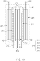
- FIG. 3 is a cross-sectional view illustrating a first unit cell applied to a method for manufacturing cell performance according to an embodiment of the present invention
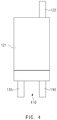
- FIG. 4 is a plan view illustrating the first unit cell applied to the method for manufacturing the cell performance according to an embodiment of the present invention.
- a method for manufacturing cell performance is a method for measuring performance of a unit cell 110 and comprises an additional lamination step of further laminating a counter electrode 121 on the outermost side of the unit cell 110, in which a first electrode 111, a separator 114, and a second electrode 112 are alternately laminated to be bonded to each other, and an outer interface analysis step of measuring a difference in performance between interfaces of the first electrode 111 and the counter electrode 121.
- the method for manufacturing the cell performance according to an embodiment of the present invention may further comprise an inner interface analysis step of measuring a difference in performance between interfaces of the first electrode 111 and the second electrode 112.
- FIG. 5 is a cross-sectional view illustrating a second unit cell applied to the method for manufacturing the cell performance according to an embodiment of the present invention
- FIG. 6 is a plan view illustrating the second unit cell applied to the method for manufacturing the cell performance according to an embodiment of the present invention.
- the method for measuring the cell performance is a method for measuring performance of a unit cell 110 in which the first electrode 111 comprising a first electrode tab 115, the separator 114, and the second electrode 112 comprising a second electrode tab 116 are alternately laminated to be bonded to each other.
- counter electrodes 121 which have the same polarity as that of the second electrode 112 at sides opposite to the first electrode 111 on the outermost sides of the unit cell 110 and each of which is provided with a third electrode tab 122 may be laminated with the separator 114 therebetween.
- the first electrode tab 115 and the second electrode tab 116 may extend in one direction of the unit cell 110
- the third electrode tab 122 may extend in the other direction of the unit cell 110.
- the counter electrodes 121 may be laminated on the outside of the first electrode 111 in a non-bonding manner. Also, in the additional lamination step, for another example, the counter electrodes 121 may be laminated on the outside of the first electrode 111 so as to be laminated in a bonding manner.
- the unit cell 110 may be provided as, for example, a bi-cell in which the second electrode 112 is disposed at a central side, and the first electrode 111 is disposed at each of both sides with respect to the second electrode 112.
- the bi-cell may be provided in plurality. At least one bi-cell of the plurality of bi-cells may be provided as a first bi-cell (unit cell) in which the first electrode 111 is provided as a negative electrode, and the second electrode 112 is provided as a positive electrode. Referring to FIGS. 5 and 6 , at least the other bi-cell may be provided as a second bi-cell (unit cell) in which the positive electrode 211 is provided as a positive electrode, and the second electrode 212 is provided as a negative electrode.
- a first bi-cell unit cell
- the second electrode 112 is provided as a positive electrode
- the other bi-cell may be provided as a second bi-cell (unit cell) in which the positive electrode 211 is provided as a positive electrode, and the second electrode 212 is provided as a negative electrode.
- the first electrode tab 215 may be disposed on the first electrode 211
- the second electrode tab 216 may be disposed on the second electrode 212
- the third electrode tab 222 may be disposed on the counter electrode 221.
- each of the first electrode tab 215, the second electrode tab 216, and the third electrode tab 222 may be electrically connected to a measurement unit.
- the separator 214 may insulate the first electrode 211, the second electrode 212, and the counter electrode 221 from each other.
- FIG. 7 is a plan view illustrating a concept of measuring performance of the first unit cell in the outer interface analysis step and the inner interface analysis step in the method for manufacturing the cell performance according to an embodiment of the present invention
- FIG. 8 is a cross-sectional view illustrating a measurement region of the first unit cell in the outer interface analysis step and the inner interface analysis step in the method for manufacturing the cell performance according to an embodiment of the present invention.
- FIG. 9 is a plan view illustrating a concept of measuring performance of the second unit cell in the outer interface analysis step and the inner interface analysis step in the method for manufacturing the cell performance according to an embodiment of the present invention
- FIG. 10 is a cross-sectional view illustrating a measurement region of the second unit cell in the outer interface analysis step and the inner interface analysis step in the method for manufacturing the cell performance according to an embodiment of the present invention.
- performance of an outer region CO of the unit cell 110 may be analyzed. That is, a difference in performance between interfaces of the first electrode 111, which is disposed at the outermost side in the unit cell 110, and the counter electrode 121 may be measured.
- the first electrode tab 115 disposed on the first electrode 111 and the third electrode tab 122 disposed on the counter electrode 121 may be electrically connected to each other to measure a difference in performance between the interfaces of the first electrode 111 and the counter electrode 121.
- the outer interface analysis step after the unit cell 110 is immersed in an electrolyte, a difference in performance between the interfaces of the first electrode 111, which is disposed at the outermost side in the unit cell 110, and the counter electrode 121 may be measured.
- the measurement unit 150 may measure a difference in performance between the interfaces by measuring a resistance value or a current value.
- the measurement unit 150 may comprises a resistance measurement part (not shown) for measuring a resistance value, a voltage measurement part (not shown) for measuring a voltage value, and a capacity measurement part for measuring a battery capacity.
- each of outer interfaces of the plurality of unit cells 110 may be analyzed to compare and analyze cell performance between the outer interfaces.
- cell performance between the interfaces when the first electrode 111 and the counter electrode 121 are bonded to each other and when the interfaces when the first electrode 111 and the counter electrode 121 are not bonded to each other may be measured to analyze a difference in performance between the interfaces when the counter electrode 121 is bonded and is not bonded to the first electrode 111.
- each of outer interfaces of the first bi-cell 110 and the second bi-cell 210 may be analyzed to analyze cell performance between the first bi-cell 110 and the second bi-cell 210.
- performance of an inner region CI of the unit cell may be analyzed. That is, a difference in performance between interfaces of the second electrode 112, which is disposed at the outermost side in the unit cell 110, and the first electrode 111, which is disposed at a central portion, may be measured.
- the second electrode tab 116 disposed on the second electrode 112 and the first electrode tab 115 disposed on the first electrode 111 may be electrically connected to each other to measure a difference in performance between the interfaces of the first electrode 111 and the second electrode 112.
- a difference in performance between the interfaces of the second electrode 112, which is disposed at the outermost side in the unit cell 110, and the first electrode 110, which is disposed at a central portion, may be measured.
- the measurement unit 150 may measure the resistance value or the current value to measure a difference in performance between the interfaces.
- the resistance value decreases, or the current value increases, it may be determined that the performance between the interfaces is improved.
- each of the difference in performance between the interfaces of the first bi-cell 110 and the difference in performance between the interfaces of the second bi-cell 210 may be measured to analyze a difference in cell performance between the first bi-cell 110 and the second bi-cell 210. That is, in the outer interface analysis step and the inner interface analysis step, cell performance in the outer region CO and the inner region CI of the first bi-cell 110 and cell performance in an outer region AO and an inner region AI of the first bi-cell 210 may be compared and analyzed with each other.
- the outer interface analysis step and the inner interface analysis step may be performed at the same time to analyze performance of entire regions CF and AF of the first bi-cell 110 and the second bi-cell 210. That is, the outer interface analysis step and the inner interface analysis step may be performed at the same time to measure the total resistance value and current value of the first bi-cell 110 and the total resistance value and current value of the second bi-cell 210, thereby comparing the resistance values and the current values of the first bi-cell 110 and the second bi-cell 210 to each other so as to analyze a difference in cell performance.
- the first electrode tabs 115 and 215 disposed on the first electrodes 111 and 211 and the third electrode tabs 122 and 222 disposed on the counter electrodes 121 may be electrically connected to each other, and the second electrode tabs 116 and 216 disposed on the second electrodes 112 and 212 and the first electrode tabs 115 and 215 disposed on the first electrodes 111 and 211 may be electrically connected to each other to measure each of differences in performance between the entire interfaces of the first bi-cell 110 and the second bi-cell 210, thereby comparing and analyzing the differences in performance therebetween.
- a charging and discharging curve is represented through the total measured resistance values and the total measured current values of the first bi-cell 110 and the second bi-cell 210, and characteristics of the charging and discharging curve may be confirmed to determine the cell performance.
- a current-voltage curve or an internal resistance value may be confirmed through the total measured resistance values and the total measured current values. For example, direct current internal resistance (DCIR) and hybrid pulse power characterization (HPPC) may be confirmed by using the current-voltage curve.
- DCIR direct current internal resistance
- HPPC hybrid pulse power characterization
- FIG. 11 is a perspective view illustrating an accommodation step of accommodating a first unit cell in a method for manufacturing cell performance according to another embodiment of the present invention
- FIG. 12 is a perspective view illustrating a state in which the first unit cell is accommodated in the method for manufacturing the cell performance according to another embodiment of the present invention
- FIG. 13 is a perspective view illustrating a state in which a second unit cell is accommodated in the method for manufacturing the cell performance according to another embodiment of the present invention.
- a method for measuring performance of a unit cell 110 in which a first electrode 111 provided with a first electrode tab 115, a separator 114, and a second electrode 112 provided with a second electrode tab 116 are alternately laminated to be bonded to each other comprises an additional lamination step of further laminating a counter electrode 121 provided with a third electrode tab 122 at the outermost side of the unit cell 110, an outer interface analysis step of measuring a difference in performance between interfaces of the first electrode 111 and the counter electrode 121, an inner interface analysis step of measuring a difference in performance between the first electrode 111 and the second electrode 112, and an accommodation step of accommodating the unit cell 110 together with an electrolyte in an accommodation part 131 of a battery case 130 to seal the battery case 130. (see FIG. 3 )
- the method for measuring the cell performance according to another embodiment of the present invention is different from the method for measuring the cell performance according to the foregoing embodiment of the present invention in that the accommodation step of accommodating the unit cell 110 together with the electrolyte in the battery case 130 is further performed.
- the accommodation step of accommodating the unit cell 110 together with the electrolyte in the battery case 130 is further performed.
- the counter electrodes 121 which have the same polarity as that of the second electrode 112 at sides opposite to the first electrode 111 on the outermost sides of the unit cell 110 and each of which is provided with a third electrode tab 122 may be laminated with the separator 114 therebetween.
- first electrode tab 115 and the second electrode tab 116 may extend in one direction of the unit cell 110, and the third electrode tab 122 may extend in the other direction of the unit cell 110.
- the unit cell 110 may be provided as, for example, a bi-cell in which the second electrode 112 is disposed at a central side, and the first electrode 111 is disposed at each of both sides with respect to the second electrode 112.
- the counter electrode 121 may be laminated on each of both the outermost sides of the bi-cell.
- the counter electrodes 121 may be laminated on the outside of the first electrode 111 in a non-bonding manner.
- the counter electrodes 121 may be laminated on the outside of the first electrode 111 so as to be laminated in a bonding manner.
- the bi-cell may be provided in plurality. At least one bi-cell of the plurality of bi-cells may be provided as a first bi-cell in which the first electrode 111 is provided as a negative electrode, and the second electrode 112 is provided as a positive electrode, and at least the other bi-cell may be provided as a second bi-cell in which the positive electrode 111 is provided as a positive electrode, and the second electrode 112 is provided as a negative electrode. (see FIG. 5 )
- the unit cell 110 may be accommodated together with the electrolyte in the battery case 130 after the additional lamination step is performed.
- the accommodation step may further comprise a lead connection step of connecting a first electrode lead 117 to the first electrode tab 115, connecting a second electrode lead 118 to the second electrode tab 116, and connecting a third electrode lead 123 to the third electrode tab 122.
- first electrode lead 117, the second electrode lead 118, and the third electrode lead 123 may protrude to the outside of the battery case 130.
- the first electrode lead 117, the second electrode lead 118, and the third electrode lead 123 may be electrically connected to a measurement unit 150.
- the measurement unit 150 may be electrically connected to the first electrode tab 115 through the first electrode lead 117, be connected to the second electrode tab 116 through the second electrode lead 118, and be connected to the third electrode tab 122 through the third electrode lead 123. (see FIG. 7 ).
- the first bi-cell 110 may be accommodated together with the electrolyte in the battery case 130 to form a first secondary battery 100
- the second bi-cell 210 may be accommodated together with the electrolyte in the battery case 130 to form a second secondary battery 200. (see FIG. 5 ) Thereafter, when measuring performance of the first bi-cell (unit cell) 110 and the second bi-cell (unit cell) 210, performance of the first secondary battery 100 and the second secondary battery 200 may be measured.
- the second electrode tab 116 disposed on the second electrode 112 and the first electrode tab 115 disposed on the first electrode 111 may be electrically connected to each other to measure a difference in performance between the interfaces of the first electrode 111 and the second electrode 112.
- the first electrode tab 115 and the second electrode tab 122 may be electrically connected to the measurement unit 150 through the first electrode lead 117 and the second electrode lead 118. (see FIG. 7 )
- the first electrode tab 115 disposed on the first electrode 111 and the third electrode tab 122 disposed on the counter electrode 121 may be electrically connected to each other to measure a difference in performance between the interfaces of the first electrode 111 and the counter electrode 121.
- the first electrode tab 115 and the third electrode tab 122 may be electrically connected to the measurement unit 150 through the first electrode lead 117 and the third electrode lead 123. (see FIG. 7 )
- each of the difference in performance between the interfaces of the first bi-cell 110 and the difference in performance between the interfaces of the second bi-cell 210 may be measured to analyze a difference in cell performance between the first bi-cell 110 and the second bi-cell 210. (see FIG. 5 )
- FIG. 14 is a graph illustrating results obtained by measuring performance of a first bi-cell and a second bi-cell through the method for manufacturing the cell performance according to an embodiment of the present invention.
- each of differences in performance between outer interfaces, inner interfaces, and entire interfaces of the first and second bi-cells was measured.
- a vertical axis represents direct current internal resistance (DCIP)
- a horizontal axis represents a state of charge (SOC).
- a counter electrodes was laminated at each of the outermost sides of the first bi-cell and the second bi-cell.
- an outer interface resistance value C-O of the first bi-cell is less than an outer interface resistance value A-O of the second bi-cell
- an inner interface resistance value C-I of the first bi-cell is greater than an inner interface resistance value A-I of the second bi-cell
- a total resistance value C-F of the first bi-cell is less than a total resistance value A-F of the second bi-cell.
- the cell performance of the first bi-cell is better than the cell performance of the second bi-cell in FIG. 14 because the total resistance value C-F of the first bi-cell is less than the total resistance value A-F of the second bi-cell even though the outer interface resistance value C-O of the first bi-cell is less than the outer interface resistance value A-O of the second bi-cell, and the inner interface resistance value C-I of the first bi-cell is greater than the inner interface resistance value A-I of the second bi-cell.
- the performance of the unit cells having the various shapes may be more easily determined through the above-described method for measuring the cell performance.
- FIG. 15 is a graph illustrating results obtained by measuring charging and discharging performance of the first bi-cell and the second bi-cell through the method for manufacturing the cell performance according to an embodiment of the present invention.
- each of differences in performance between entire interfaces comprising outer interfaces and inner interfaces of the first and second bi-cells was measured.
- a vertical axis represents a voltage V
- a horizontal axis represents a charge and discharge capacity (mAh).
- a counter electrodes was laminated at each of the outermost sides of the first bi-cell and the second bi-cell.
- a value obtained by measuring each of the total resistance value and the total current value by electrically connecting the first electrode tab, the second electrode tab, and the third electrode tab of the first bi-cell and the second bi-cell to a resistance and current measurement unit was shown in a charging and discharging curve. That is, the resistance value and the current value were measured to extract a voltage value and a capacitance value.
- the measurements were performed under conditions of 10% SOC and 25°C.
- a voltage value C of the entire interface of the first bi-cell is greater than a voltage value A of the total interface of the second bi-cell.
- the discharge capacity of the entire interface of the first bi-cell is larger than the discharge capacity of the second bi-cell. Therefore, it is seen that the charge and discharge performance of the entire interface of the first bi-cell is better than the charge and discharge performance of the entire interface of the second bi-cell.
- the performance of the unit cells having the various shapes may be more easily determined through the above-described method for measuring the cell performance.
Landscapes
- Chemical & Material Sciences (AREA)
- Chemical Kinetics & Catalysis (AREA)
- Electrochemistry (AREA)
- General Chemical & Material Sciences (AREA)
- Engineering & Computer Science (AREA)
- Manufacturing & Machinery (AREA)
- Physics & Mathematics (AREA)
- General Physics & Mathematics (AREA)
- Secondary Cells (AREA)
Abstract
Description
- The present application claims the benefit of the priority of
Korean Patent Application No. 10-2018-0151257, filed on November 29, 2018 - The present invention relates to a method for measuring cell performance.
- Secondary batteries are rechargeable unlike primarily batteries, and also, the possibility of compact size and high capacity is high. Thus, recently, many studies on secondary batteries are being carried out. As technology development and demands for mobile devices increase, the demands for secondary batteries as energy sources are rapidly increasing.
- Rechargeable batteries are classified into coin type batteries, cylindrical type batteries, prismatic type batteries, and pouch type batteries according to a shape of a battery case. In such a secondary battery, an electrode assembly mounted in a battery case is a chargeable and dischargeable power generating device having a structure in which an electrode and a separator are stacked.
- The electrode assembly may be approximately classified into a jelly-roll type electrode assembly in which a separator is interposed between a positive electrode and a negative electrode, each of which is provided as the form of a sheet coated with an active material, and then, the positive electrode, the separator, and the negative electrode are wound, a stacked type electrode assembly in which a plurality of positive and negative electrodes with a separator therebetween are sequentially stacked, and a stack/folding type electrode assembly in which stacked type unit cells are wound together with a separation film having a long length.
- Recently, the pouch-type battery in which a stack/folding type electrode assembly is built in a pouch-type battery case provided as an aluminum lamination sheet is attracting much attention due to its low manufacturing cost, small weight, easy shape deformation, and the like, and thus, its usage is gradually increasing.
-
FIG. 1 is a plan view illustrating a state before a stack & folding cell is folded according to the related art, andFIG. 2 is a perspective view illustrating the state after a stack & folding cell is folded according to the related art. - Referring to
FIGS. 1 and2 , in a stack/foldingtype electrode assembly 10, a plurality ofunit cells 12 are stacked on aseparation film 11 so as to be spaced a predetermined distance from each other and then sequentially filed in one direction to form theelectrode assembly 10. - However, it is difficult to analyze cell performance with respect to the
unit cells 12 of the stack/folding electrode assembly 10. - [PATENT DOCUMENTS]
Korean Patent Publication No. 10-2014-0015647 - One aspect of the present invention is to provide a method for measuring cell performance, which is capable of analyzing the performance of unit cells of a stack/folding type electrode assembly.
- A method for manufacturing performance of a unit cell, in which a first electrode provided with a first electrode tab, a separator, and a second electrode provided with a second electrode tab are alternately laminated to be bonded to each other, according to an embodiment of the present invention comprises: an additional lamination step of further laminating counter electrodes, each of which has the same polarity as that of the second electrode and is provided with a third electrode tab, on sides facing the first electrode at the outermost sides of the unit cell with the separator therebetween; and an outer interface analysis step of measuring a different in performance between the first electrode and each of the counter electrodes by electrically connecting the first electrode tab disposed on the first electrode to the third electrode tab disposed on the counter electrode.
- According to the present invention, the counter electrodes may be further provided on the outer surface of the unit cell to measure a difference in performance between the interfaces, thereby analyzing the performance of the unit cell.
-
-
FIG. 1 is a plan view illustrating a state before a stack & folding cell is folded according to the related art. -
FIG. 2 is a perspective view illustrating the state after a stack & folding cell is folded according to the related art. -
FIG. 3 is a cross-sectional view illustrating a first unit cell applied to a method for manufacturing cell performance according to an embodiment of the present invention. -
FIG. 4 is a plan view illustrating the first unit cell applied to the method for manufacturing the cell performance according to an embodiment of the present invention. -
FIG. 5 is a cross-sectional view illustrating a second unit cell applied to the method for manufacturing the cell performance according to an embodiment of the present invention. -
FIG. 6 is a plan view illustrating the second unit cell applied to the method for manufacturing the cell performance according to an embodiment of the present invention. -
FIG. 7 is a plan view illustrating a concept of measuring performance of the first unit cell in an outer interface analysis step and an inner interface analysis step in the method for manufacturing the cell performance according to an embodiment of the present invention. -
FIG. 8 is a cross-sectional view illustrating a measurement region of the first unit cell in the outer interface analysis step and the inner interface analysis step in the method for manufacturing the cell performance according to an embodiment of the present invention. -
FIG. 9 is a plan view illustrating a concept of measuring performance of the second unit cell in the outer interface analysis step and the inner interface analysis step in the method for manufacturing the cell performance according to an embodiment of the present invention. -
FIG. 10 is a cross-sectional view illustrating a measurement region of the second unit cell in the outer interface analysis step and the inner interface analysis step in the method for manufacturing the cell performance according to an embodiment of the present invention. -
FIG. 11 is a perspective view illustrating an accommodation step of accommodating a first unit cell in a method for manufacturing cell performance according to another embodiment of the present invention. -
FIG. 12 is a perspective view illustrating a state in which the first unit cell is accommodated in the method for manufacturing the cell performance according to another embodiment of the present invention. -
FIG. 13 is a perspective view illustrating a state in which a second unit cell is accommodated in the method for manufacturing the cell performance according to another embodiment of the present invention. -
FIG. 14 is a graph illustrating results obtained by measuring performance of a first bi-cell and a second bi-cell through the method for manufacturing the cell performance according to an embodiment of the present invention. -
FIG. 15 is a graph illustrating results obtained by measuring charging and discharging performance of the first bi-cell and the second bi-cell through the method for manufacturing the cell performance according to an embodiment of the present invention. - The objectives, specific advantages, and novel features of the present invention will become more apparent from the following detailed description taken in conjunction with the accompanying drawings. It should be noted that the reference numerals are added to the components of the drawings in the present specification with the same numerals as possible, even if they are illustrated in other drawings. Also, the present invention may be embodied in different forms and should not be construed as limited to the embodiments set forth herein. In the following description of the present invention, the detailed descriptions of related arts which may unnecessarily obscure the gist of the present invention will be omitted.
-
FIG. 3 is a cross-sectional view illustrating a first unit cell applied to a method for manufacturing cell performance according to an embodiment of the present invention, andFIG. 4 is a plan view illustrating the first unit cell applied to the method for manufacturing the cell performance according to an embodiment of the present invention. - Referring to
FIGS. 3 and4 , a method for manufacturing cell performance according to an embodiment of the present invention is a method for measuring performance of aunit cell 110 and comprises an additional lamination step of further laminating acounter electrode 121 on the outermost side of theunit cell 110, in which afirst electrode 111, aseparator 114, and asecond electrode 112 are alternately laminated to be bonded to each other, and an outer interface analysis step of measuring a difference in performance between interfaces of thefirst electrode 111 and thecounter electrode 121. - Also, the method for manufacturing the cell performance according to an embodiment of the present invention may further comprise an inner interface analysis step of measuring a difference in performance between interfaces of the
first electrode 111 and thesecond electrode 112. -
FIG. 5 is a cross-sectional view illustrating a second unit cell applied to the method for manufacturing the cell performance according to an embodiment of the present invention, andFIG. 6 is a plan view illustrating the second unit cell applied to the method for manufacturing the cell performance according to an embodiment of the present invention. - Hereinafter, the method for manufacturing the cell performance according to an embodiment of the present invention will be described in more detail with reference to
FIGS. 1 to 10 . - Referring to
FIGS. 3 and4 , the method for measuring the cell performance according to an embodiment of the present invention is a method for measuring performance of aunit cell 110 in which thefirst electrode 111 comprising afirst electrode tab 115, theseparator 114, and thesecond electrode 112 comprising asecond electrode tab 116 are alternately laminated to be bonded to each other. - In the additional lamination step,
counter electrodes 121 which have the same polarity as that of thesecond electrode 112 at sides opposite to thefirst electrode 111 on the outermost sides of theunit cell 110 and each of which is provided with athird electrode tab 122 may be laminated with theseparator 114 therebetween. Here, for example, thefirst electrode tab 115 and thesecond electrode tab 116 may extend in one direction of theunit cell 110, and thethird electrode tab 122 may extend in the other direction of theunit cell 110. - Furthermore, in the additional lamination step, for example, the
counter electrodes 121 may be laminated on the outside of thefirst electrode 111 in a non-bonding manner. Also, in the additional lamination step, for another example, thecounter electrodes 121 may be laminated on the outside of thefirst electrode 111 so as to be laminated in a bonding manner. - The
unit cell 110 may be provided as, for example, a bi-cell in which thesecond electrode 112 is disposed at a central side, and thefirst electrode 111 is disposed at each of both sides with respect to thesecond electrode 112. - Here, referring to
FIGS. 3 and4 , the bi-cell may be provided in plurality. At least one bi-cell of the plurality of bi-cells may be provided as a first bi-cell (unit cell) in which thefirst electrode 111 is provided as a negative electrode, and thesecond electrode 112 is provided as a positive electrode. Referring toFIGS. 5 and6 , at least the other bi-cell may be provided as a second bi-cell (unit cell) in which thepositive electrode 211 is provided as a positive electrode, and thesecond electrode 212 is provided as a negative electrode. Here, referring toFIGS. 3 to 6 , in thesecond bi-cell 210, like thefirst bi-cell 110, thefirst electrode tab 215 may be disposed on thefirst electrode 211, thesecond electrode tab 216 may be disposed on thesecond electrode 212, and thethird electrode tab 222 may be disposed on thecounter electrode 221. Thus, each of thefirst electrode tab 215, thesecond electrode tab 216, and thethird electrode tab 222 may be electrically connected to a measurement unit. Here, theseparator 214 may insulate thefirst electrode 211, thesecond electrode 212, and thecounter electrode 221 from each other. -
FIG. 7 is a plan view illustrating a concept of measuring performance of the first unit cell in the outer interface analysis step and the inner interface analysis step in the method for manufacturing the cell performance according to an embodiment of the present invention, andFIG. 8 is a cross-sectional view illustrating a measurement region of the first unit cell in the outer interface analysis step and the inner interface analysis step in the method for manufacturing the cell performance according to an embodiment of the present invention. -
FIG. 9 is a plan view illustrating a concept of measuring performance of the second unit cell in the outer interface analysis step and the inner interface analysis step in the method for manufacturing the cell performance according to an embodiment of the present invention, andFIG. 10 is a cross-sectional view illustrating a measurement region of the second unit cell in the outer interface analysis step and the inner interface analysis step in the method for manufacturing the cell performance according to an embodiment of the present invention. - Referring to
FIGS. 3 ,4 ,7 , and8 , in the outer interface analysis step, performance of an outer region CO of theunit cell 110 may be analyzed. That is, a difference in performance between interfaces of thefirst electrode 111, which is disposed at the outermost side in theunit cell 110, and thecounter electrode 121 may be measured. Here, in the outer interface analysis step, thefirst electrode tab 115 disposed on thefirst electrode 111 and thethird electrode tab 122 disposed on thecounter electrode 121 may be electrically connected to each other to measure a difference in performance between the interfaces of thefirst electrode 111 and thecounter electrode 121. Here, in the outer interface analysis step, after theunit cell 110 is immersed in an electrolyte, a difference in performance between the interfaces of thefirst electrode 111, which is disposed at the outermost side in theunit cell 110, and thecounter electrode 121 may be measured. - Also, in the outer interface analysis step, the measurement unit 150 (measurement unit brand name: PNE, voltage value: 0-5V/8A, and error range: ± 0.1%) may measure a difference in performance between the interfaces by measuring a resistance value or a current value. Here, in the outer interface analysis step, the more the resistance value decreases, or the current value increases, the more the performance between the interfaces is improved. Here, the
measurement unit 150 may comprises a resistance measurement part (not shown) for measuring a resistance value, a voltage measurement part (not shown) for measuring a voltage value, and a capacity measurement part for measuring a battery capacity. - In the outer interface analysis step, each of outer interfaces of the plurality of
unit cells 110 may be analyzed to compare and analyze cell performance between the outer interfaces. Here, in the outer interface analysis step, for example, cell performance between the interfaces when thefirst electrode 111 and thecounter electrode 121 are bonded to each other and when the interfaces when thefirst electrode 111 and thecounter electrode 121 are not bonded to each other may be measured to analyze a difference in performance between the interfaces when thecounter electrode 121 is bonded and is not bonded to thefirst electrode 111. Also, referring toFIGS. 3 and5 , in the outer interface analysis step, for example, each of outer interfaces of thefirst bi-cell 110 and thesecond bi-cell 210 may be analyzed to analyze cell performance between thefirst bi-cell 110 and thesecond bi-cell 210. - Referring to
FIGS. 7 and8 , in the inner interface analysis step, performance of an inner region CI of the unit cell may be analyzed. That is, a difference in performance between interfaces of thesecond electrode 112, which is disposed at the outermost side in theunit cell 110, and thefirst electrode 111, which is disposed at a central portion, may be measured. Here, in the inner interface analysis step, thesecond electrode tab 116 disposed on thesecond electrode 112 and thefirst electrode tab 115 disposed on thefirst electrode 111 may be electrically connected to each other to measure a difference in performance between the interfaces of thefirst electrode 111 and thesecond electrode 112. Here, in the outer interface analysis step, after theunit cell 110 is immersed in the electrolyte, a difference in performance between the interfaces of thesecond electrode 112, which is disposed at the outermost side in theunit cell 110, and thefirst electrode 110, which is disposed at a central portion, may be measured. - Also, in the inner interface analysis step, the
measurement unit 150 may measure the resistance value or the current value to measure a difference in performance between the interfaces. Here, in the inner interface analysis step, as the resistance value decreases, or the current value increases, it may be determined that the performance between the interfaces is improved. - Referring to
FIGS. 7 to 10 , in the outer interface analysis step and the inner interface analysis step, each of the difference in performance between the interfaces of thefirst bi-cell 110 and the difference in performance between the interfaces of thesecond bi-cell 210 may be measured to analyze a difference in cell performance between thefirst bi-cell 110 and thesecond bi-cell 210. That is, in the outer interface analysis step and the inner interface analysis step, cell performance in the outer region CO and the inner region CI of thefirst bi-cell 110 and cell performance in an outer region AO and an inner region AI of thefirst bi-cell 210 may be compared and analyzed with each other. - The outer interface analysis step and the inner interface analysis step may be performed at the same time to analyze performance of entire regions CF and AF of the
first bi-cell 110 and thesecond bi-cell 210. That is, the outer interface analysis step and the inner interface analysis step may be performed at the same time to measure the total resistance value and current value of thefirst bi-cell 110 and the total resistance value and current value of thesecond bi-cell 210, thereby comparing the resistance values and the current values of thefirst bi-cell 110 and thesecond bi-cell 210 to each other so as to analyze a difference in cell performance. That is, in thefirst bi-cell 110 and thesecond bi-cell 210, thefirst electrode tabs first electrodes third electrode tabs counter electrodes 121 may be electrically connected to each other, and thesecond electrode tabs second electrodes first electrode tabs first electrodes first bi-cell 110 and thesecond bi-cell 210, thereby comparing and analyzing the differences in performance therebetween. Here, a charging and discharging curve is represented through the total measured resistance values and the total measured current values of thefirst bi-cell 110 and thesecond bi-cell 210, and characteristics of the charging and discharging curve may be confirmed to determine the cell performance. Also, a current-voltage curve or an internal resistance value may be confirmed through the total measured resistance values and the total measured current values. For example, direct current internal resistance (DCIR) and hybrid pulse power characterization (HPPC) may be confirmed by using the current-voltage curve. - Hereinafter, a method for manufacturing cell performance according to another embodiment of the present invention will be described.
-
FIG. 11 is a perspective view illustrating an accommodation step of accommodating a first unit cell in a method for manufacturing cell performance according to another embodiment of the present invention,FIG. 12 is a perspective view illustrating a state in which the first unit cell is accommodated in the method for manufacturing the cell performance according to another embodiment of the present invention, andFIG. 13 is a perspective view illustrating a state in which a second unit cell is accommodated in the method for manufacturing the cell performance according to another embodiment of the present invention. - Referring to
FIGS. 3 and11 , a method for measuring performance of aunit cell 110 in which afirst electrode 111 provided with afirst electrode tab 115, aseparator 114, and asecond electrode 112 provided with asecond electrode tab 116 are alternately laminated to be bonded to each other comprises an additional lamination step of further laminating acounter electrode 121 provided with athird electrode tab 122 at the outermost side of theunit cell 110, an outer interface analysis step of measuring a difference in performance between interfaces of thefirst electrode 111 and thecounter electrode 121, an inner interface analysis step of measuring a difference in performance between thefirst electrode 111 and thesecond electrode 112, and an accommodation step of accommodating theunit cell 110 together with an electrolyte in anaccommodation part 131 of abattery case 130 to seal thebattery case 130. (seeFIG. 3 ) - The method for measuring the cell performance according to another embodiment of the present invention is different from the method for measuring the cell performance according to the foregoing embodiment of the present invention in that the accommodation step of accommodating the
unit cell 110 together with the electrolyte in thebattery case 130 is further performed. Thus, contents of this embodiment, which are duplicated with those according to the foregoing embodiment, will be briefly described, and also, differences therebetween will be mainly described. - In more detail, in the method for measuring the cell performance according to another embodiment of the present invention, in the additional lamination step, the
counter electrodes 121 which have the same polarity as that of thesecond electrode 112 at sides opposite to thefirst electrode 111 on the outermost sides of theunit cell 110 and each of which is provided with athird electrode tab 122 may be laminated with theseparator 114 therebetween. - Here, for example, the
first electrode tab 115 and thesecond electrode tab 116 may extend in one direction of theunit cell 110, and thethird electrode tab 122 may extend in the other direction of theunit cell 110. - The
unit cell 110 may be provided as, for example, a bi-cell in which thesecond electrode 112 is disposed at a central side, and thefirst electrode 111 is disposed at each of both sides with respect to thesecond electrode 112. - In addition, in the additional lamination step, the
counter electrode 121 may be laminated on each of both the outermost sides of the bi-cell. - Furthermore, in the additional lamination step, for example, the
counter electrodes 121 may be laminated on the outside of thefirst electrode 111 in a non-bonding manner. - Also, in the additional lamination step, for another example, the
counter electrodes 121 may be laminated on the outside of thefirst electrode 111 so as to be laminated in a bonding manner. - The bi-cell may be provided in plurality. At least one bi-cell of the plurality of bi-cells may be provided as a first bi-cell in which the
first electrode 111 is provided as a negative electrode, and thesecond electrode 112 is provided as a positive electrode, and at least the other bi-cell may be provided as a second bi-cell in which thepositive electrode 111 is provided as a positive electrode, and thesecond electrode 112 is provided as a negative electrode. (seeFIG. 5 ) - Referring to
FIGS. 2 and11 to 13 , in the accommodation step, theunit cell 110 may be accommodated together with the electrolyte in thebattery case 130 after the additional lamination step is performed. - Also, in the method for manufacturing the cell performance according to another embodiment of the present invention, the accommodation step may further comprise a lead connection step of connecting a
first electrode lead 117 to thefirst electrode tab 115, connecting asecond electrode lead 118 to thesecond electrode tab 116, and connecting athird electrode lead 123 to thethird electrode tab 122. - Ends of the
first electrode lead 117, thesecond electrode lead 118, and thethird electrode lead 123 may protrude to the outside of thebattery case 130. Here, thefirst electrode lead 117, thesecond electrode lead 118, and thethird electrode lead 123 may be electrically connected to ameasurement unit 150. Thus, themeasurement unit 150 may be electrically connected to thefirst electrode tab 115 through thefirst electrode lead 117, be connected to thesecond electrode tab 116 through thesecond electrode lead 118, and be connected to thethird electrode tab 122 through thethird electrode lead 123. (seeFIG. 7 ). - Here, the
first bi-cell 110 may be accommodated together with the electrolyte in thebattery case 130 to form a firstsecondary battery 100, and thesecond bi-cell 210 may be accommodated together with the electrolyte in thebattery case 130 to form a secondsecondary battery 200. (seeFIG. 5 ) Thereafter, when measuring performance of the first bi-cell (unit cell) 110 and the second bi-cell (unit cell) 210, performance of the firstsecondary battery 100 and the secondsecondary battery 200 may be measured. - Referring to
FIG. 8 , in the inner interface analysis step, thesecond electrode tab 116 disposed on thesecond electrode 112 and thefirst electrode tab 115 disposed on thefirst electrode 111 may be electrically connected to each other to measure a difference in performance between the interfaces of thefirst electrode 111 and thesecond electrode 112. Here, in the inner interface analysis step, thefirst electrode tab 115 and thesecond electrode tab 122 may be electrically connected to themeasurement unit 150 through thefirst electrode lead 117 and thesecond electrode lead 118. (seeFIG. 7 ) - In the outer interface analysis step, the
first electrode tab 115 disposed on thefirst electrode 111 and thethird electrode tab 122 disposed on thecounter electrode 121 may be electrically connected to each other to measure a difference in performance between the interfaces of thefirst electrode 111 and thecounter electrode 121. Here, in the outer interface analysis step, thefirst electrode tab 115 and thethird electrode tab 122 may be electrically connected to themeasurement unit 150 through thefirst electrode lead 117 and thethird electrode lead 123. (seeFIG. 7 ) - Referring to
FIGS. 8 to 10 , in the outer interface analysis step and the inner interface analysis step, each of the difference in performance between the interfaces of thefirst bi-cell 110 and the difference in performance between the interfaces of thesecond bi-cell 210 may be measured to analyze a difference in cell performance between thefirst bi-cell 110 and thesecond bi-cell 210. (seeFIG. 5 ) -
FIG. 14 is a graph illustrating results obtained by measuring performance of a first bi-cell and a second bi-cell through the method for manufacturing the cell performance according to an embodiment of the present invention. - Referring to
FIG. 14 , each of differences in performance between outer interfaces, inner interfaces, and entire interfaces of the first and second bi-cells was measured. In the graph ofFIG. 14 , a vertical axis represents direct current internal resistance (DCIP), and a horizontal axis represents a state of charge (SOC). Here, a counter electrodes was laminated at each of the outermost sides of the first bi-cell and the second bi-cell. Also, a value obtained by measuring each DC resistance by electrically connecting the first electrode tab, the second electrode tab, and the third electrode tab of the first bi-cell and the second bi-cell to a resistance measurement unit (measurement unit brand name: PNE, voltage value: 0-5V / 8A, and error range: ± 0.1%) was shown in a graph. - In the graph shown in
FIG. 14 , it is seen that an outer interface resistance value C-O of the first bi-cell is less than an outer interface resistance value A-O of the second bi-cell, an inner interface resistance value C-I of the first bi-cell is greater than an inner interface resistance value A-I of the second bi-cell, and a total resistance value C-F of the first bi-cell is less than a total resistance value A-F of the second bi-cell. - Thus, it is seen that the cell performance of the first bi-cell is better than the cell performance of the second bi-cell in
FIG. 14 because the total resistance value C-F of the first bi-cell is less than the total resistance value A-F of the second bi-cell even though the outer interface resistance value C-O of the first bi-cell is less than the outer interface resistance value A-O of the second bi-cell, and the inner interface resistance value C-I of the first bi-cell is greater than the inner interface resistance value A-I of the second bi-cell. - The performance of the unit cells having the various shapes may be more easily determined through the above-described method for measuring the cell performance.
-
FIG. 15 is a graph illustrating results obtained by measuring charging and discharging performance of the first bi-cell and the second bi-cell through the method for manufacturing the cell performance according to an embodiment of the present invention. - Referring to
FIG. 15 , each of differences in performance between entire interfaces comprising outer interfaces and inner interfaces of the first and second bi-cells was measured. In the graph ofFIG. 15 , a vertical axis represents a voltage V, and a horizontal axis represents a charge and discharge capacity (mAh). Here, a counter electrodes was laminated at each of the outermost sides of the first bi-cell and the second bi-cell. Also, a value obtained by measuring each of the total resistance value and the total current value by electrically connecting the first electrode tab, the second electrode tab, and the third electrode tab of the first bi-cell and the second bi-cell to a resistance and current measurement unit (measurement unit brand name: PNE, voltage value: 0-5V / 8A, and error range: ± 0.1%) was shown in a charging and discharging curve. That is, the resistance value and the current value were measured to extract a voltage value and a capacitance value. Here, the voltage value was obtained through the formula V (voltage value) = I (current value) * R (resistance value), and the capacitance value was obtained by multiplying the current value I by a time t. In addition, the measurements were performed under conditions of 10% SOC and 25°C. - It is seen that, as the discharge proceeds in the downward discharge graph shown in
FIG. 15 , a voltage value C of the entire interface of the first bi-cell is greater than a voltage value A of the total interface of the second bi-cell. In addition, it is seen that the discharge capacity of the entire interface of the first bi-cell is larger than the discharge capacity of the second bi-cell. Therefore, it is seen that the charge and discharge performance of the entire interface of the first bi-cell is better than the charge and discharge performance of the entire interface of the second bi-cell. - The performance of the unit cells having the various shapes may be more easily determined through the above-described method for measuring the cell performance.
- While the present invention has been particularly shown and described with reference to exemplary embodiments thereof, it is to be understood that the scope of the present invention is not limited to the method for manufacturing the cell performance according to the present invention. It will be understood by those of ordinary skill in the art that various changes in form and details may be made therein without departing from the spirit and scope of the invention.
- Furthermore, the scope of protection of the present invention will be clarified by the appended claims.
Claims (12)
- A method for manufacturing performance of a unit cell, in which a first electrode provided with a first electrode tab, a separator, and a second electrode provided with a second electrode tab are alternately laminated to be bonded to each other, the method comprising:an additional lamination step of further laminating counter electrodes, each of which has the same polarity as that of the second electrode and is provided with a third electrode tab, on sides facing the first electrode at the outermost sides of the unit cell with the separator therebetween; andan outer interface analysis step of measuring a different in performance between the first electrode and each of the counter electrodes by electrically connecting the first electrode tab disposed on the first electrode to the third electrode tab disposed on the counter electrode.
- The method of claim 1, further comprising an inner interface analysis step of measuring a difference in performance between interfaces of the first electrode and the second electrode by electrically connecting the second electrode tab disposed on the second electrode to the first electrode tab disposed on the first electrode.
- The method of claim 2, wherein the first electrode tab and the second electrode tab extend in one direction of the unit cell, and the third electrode tab extends in the other direction of the unit cell.
- The method of claim 2, further comprising, after performing the additional lamination step, an accommodation step of accommodating the unit cell together with an electrolyte in a battery case.
- The method of claim 4, wherein the accommodation step further comprises a lead connection step of connecting a first electrode lead to the first electrode tab, connecting a second electrode lead to the second electrode tab, and connecting a third electrode lead to the third electrode tab.
- The method of claim 2, wherein the unit cell is provided as a bi-cell in which the second electrode is disposed at a central side, and the first electrode is disposed at each of both sides with respect to the second electrode.
- The method of claim 6, wherein, in the additional lamination step, the counter electrodes are laminated on both the outermost sides of the bi-cell, respectively.
- The method of claim 7, wherein, in the additional lamination step, each of the counter electrodes is laminated on the outside of the first electrode in a non-bonding manner.
- The method of claim 7, wherein, in the additional lamination step, each of the counter electrodes is laminated on the outside of the first electrode in a bonding manner.
- The method of claim 6, wherein the bi-cell is provided in plurality,
at least one bi-cell of the plurality of bi-cells is provided as a first bi-cell in which the first electrode is provided as a negative electrode, and the second electrode is provided as a positive electrode, and
at least the other bi-cell is provided as a second bi-cell in which the first electrode is provided as a positive electrode, and the second electrode is provided as a negative electrode. - The method of claim 10, wherein, in the outer interface analysis step and the inner interface analysis step, each of a difference in performance between interfaces of the first bi-cell and a difference in performance between interfaces of the second bi-cell is measured to analyze a difference in cell performance between the first bi-cell and the second bi-cell.
- A method for manufacturing performance of a secondary battery comprising a unit cell, in which a first electrode provided with a first electrode tab, a separator, and a second electrode provided with a second electrode tab are alternately laminated to be bonded to each other and a battery case in which the unit cell is accommodated, the method comprising:an additional lamination step of further laminating counter electrodes, each of which has the same polarity as that of the second electrode and is provided with a third electrode tab, on sides facing the first electrode at the outermost sides of the unit cell with the separator therebetween; andan outer interface analysis step of measuring a different in performance between the first electrode and each of the counter electrodes by electrically connecting the first electrode tab disposed on the first electrode to the third electrode tab disposed on the counter electrode.
Applications Claiming Priority (2)
| Application Number | Priority Date | Filing Date | Title |
|---|---|---|---|
| KR1020180151257A KR102412587B1 (en) | 2018-11-29 | 2018-11-29 | Cell performance measuring method |
| PCT/KR2019/016273 WO2020111695A1 (en) | 2018-11-29 | 2019-11-25 | Cell performance measuring method |
Publications (3)
| Publication Number | Publication Date |
|---|---|
| EP3865887A1 true EP3865887A1 (en) | 2021-08-18 |
| EP3865887A4 EP3865887A4 (en) | 2021-12-15 |
| EP3865887B1 EP3865887B1 (en) | 2026-01-14 |
Family
ID=70851870
Family Applications (1)
| Application Number | Title | Priority Date | Filing Date |
|---|---|---|---|
| EP19889603.7A Active EP3865887B1 (en) | 2018-11-29 | 2019-11-25 | Method for measuring cell performance |
Country Status (6)
| Country | Link |
|---|---|
| US (1) | US12140638B2 (en) |
| EP (1) | EP3865887B1 (en) |
| KR (1) | KR102412587B1 (en) |
| CN (1) | CN113661398B (en) |
| ES (1) | ES3060118T3 (en) |
| WO (1) | WO2020111695A1 (en) |
Families Citing this family (2)
| Publication number | Priority date | Publication date | Assignee | Title |
|---|---|---|---|---|
| CN113728493B (en) * | 2021-02-09 | 2023-07-18 | 宁德新能源科技有限公司 | Electrochemical device and electronic device |
| KR102915324B1 (en) * | 2024-01-23 | 2026-01-19 | 주식회사 엘지에너지솔루션 | Apparatus and method for managing battery |
Family Cites Families (35)
| Publication number | Priority date | Publication date | Assignee | Title |
|---|---|---|---|---|
| JPS5850492B2 (en) * | 1980-01-10 | 1983-11-10 | 永楽産業株式会社 | Connectors between architectural hardware such as outlet boxes and electrical conduits |
| KR100477719B1 (en) * | 1997-08-04 | 2005-05-16 | 삼성에스디아이 주식회사 | Battery for testing interfacial resistance and testing method of resistance using the same |
| JP3720555B2 (en) * | 1997-12-15 | 2005-11-30 | ソニー株式会社 | Battery cell inspection method and battery cell inspection apparatus |
| JP2000285909A (en) | 1999-03-31 | 2000-10-13 | Mitsubishi Cable Ind Ltd | Testing device of electrode plate for lithium ion secondary battery |
| KR100515571B1 (en) | 2000-02-08 | 2005-09-20 | 주식회사 엘지화학 | Stacked electrochemical cell |
| JP3260349B2 (en) | 2000-06-05 | 2002-02-25 | 松下電器産業株式会社 | Sealant for electrochemical device and electrochemical device using the same |
| CA2467263A1 (en) * | 2003-05-14 | 2004-11-14 | Hydrogenics Corporation | Method, system and apparatus for testing electrochemical cells |
| JP4945882B2 (en) * | 2004-03-02 | 2012-06-06 | トヨタ自動車株式会社 | Fuel cell performance analysis method |
| JP4832229B2 (en) * | 2006-01-23 | 2011-12-07 | 三洋電機株式会社 | Nonaqueous electrolyte secondary battery |
| CN100481601C (en) * | 2007-05-30 | 2009-04-22 | 李文华 | Three-electrode electro chemical cell |
| JP2012079582A (en) * | 2010-10-04 | 2012-04-19 | Nec Corp | Secondary battery, method for measuring resistance of positive electrode or negative electrode of secondary battery, and method for diagnosing degree of deterioration in positive electrode or negative electrode of secondary battery |
| EP2442400A1 (en) | 2010-10-13 | 2012-04-18 | Fraunhofer-Gesellschaft zur Förderung der angewandten Forschung e.V. | Electrochemical cell based on lithium technology with internal reference electrode, process for its production and methods for simultaneous monitoring the voltage or impedance of the anode and the cathode thereof |
| JP5850492B2 (en) | 2011-10-13 | 2016-02-03 | 学校法人早稲田大学 | Battery system and battery evaluation method |
| CN104137320B (en) | 2012-04-17 | 2017-08-29 | 株式会社Lg 化学 | Lithium secondary battery with excellent performance |
| KR101528001B1 (en) | 2012-06-22 | 2015-06-10 | 주식회사 엘지화학 | Electrode assembly, manufacture thereof, and secondary batteries including same |
| JP6068241B2 (en) | 2013-04-15 | 2017-01-25 | 本田技研工業株式会社 | Method for manufacturing lithium ion battery |
| KR101761971B1 (en) * | 2013-10-10 | 2017-07-26 | 주식회사 엘지화학 | Short measuring apparatus |
| US9847558B1 (en) | 2013-10-11 | 2017-12-19 | Hrl Laboratories, Llc | Methods and apparatus for real-time characterization of batteries with a reference electrode |
| KR101636115B1 (en) | 2013-10-18 | 2016-07-04 | 주식회사 엘지화학 | Electrode assembly for lithium secondary battery and lithium secondary battery |
| JP2015088396A (en) * | 2013-11-01 | 2015-05-07 | 株式会社デンソー | Secondary battery |
| KR101681968B1 (en) * | 2013-11-26 | 2016-12-02 | 주식회사 엘지화학 | Apparatus for testing secondary battery |
| WO2015085580A1 (en) * | 2013-12-13 | 2015-06-18 | GM Global Technology Operations LLC | Incorporating reference electrodes into battery pouch cells |
| KR101688569B1 (en) * | 2014-02-06 | 2016-12-21 | 주식회사 엘지화학 | Battery Cell Having Step-formed Structure and Method for Checking Insulation Resistance Defects Thereof |
| CA2926327C (en) * | 2014-07-31 | 2018-03-13 | Kabushiki Kaisha Nihon Micronics | Testing device and testing method for sheet-shaped cell |
| CN104181436A (en) * | 2014-08-13 | 2014-12-03 | 江苏安瑞达新材料有限公司 | Method for testing lithium battery diaphragm short-circuit resistant capacity |
| JPWO2016051639A1 (en) * | 2014-09-29 | 2017-07-06 | パナソニックIpマネジメント株式会社 | Laminated battery |
| CN105261781B (en) * | 2015-10-28 | 2018-11-16 | 广东烛光新能源科技有限公司 | Electrochemical cell and preparation method thereof |
| KR102018849B1 (en) * | 2015-11-11 | 2019-09-05 | 주식회사 엘지화학 | Battery Cell Comprising Electrode Lead Having Protruding Extension Part and Tab Connection Part |
| CN106058302A (en) * | 2016-06-25 | 2016-10-26 | 芜湖格利特新能源科技有限公司 | Method for monitoring internal short circuit of battery cell employing three electrodes |
| KR102038611B1 (en) * | 2016-10-25 | 2019-10-30 | 주식회사 엘지화학 | A secondary battery and life prediction appratus for the same |
| WO2018084675A1 (en) * | 2016-11-04 | 2018-05-11 | 주식회사 엘지화학 | Reaction estimation method for secondary battery and secondary battery comprising battery cell used for same |
| CN106707185B (en) * | 2016-12-14 | 2019-06-07 | 天津力神电池股份有限公司 | A kind of flexible packing lithium ion secondary battery performance estimating method |
| KR102105172B1 (en) | 2017-01-03 | 2020-04-27 | 주식회사 엘지화학 | Battery Cell Capable of Measuring Inner Temperature thereof |
| CN107026282A (en) | 2017-06-02 | 2017-08-08 | 中天储能科技有限公司 | A kind of lithium ion battery three-electrode system and its method of testing |
| CN108107092B (en) * | 2017-11-17 | 2019-09-27 | 清华大学 | A kind of impregnation preparation method of lithium-ion battery with reference electrode |
-
2018
- 2018-11-29 KR KR1020180151257A patent/KR102412587B1/en active Active
-
2019
- 2019-11-25 CN CN201980076131.9A patent/CN113661398B/en active Active
- 2019-11-25 US US17/296,368 patent/US12140638B2/en active Active
- 2019-11-25 WO PCT/KR2019/016273 patent/WO2020111695A1/en not_active Ceased
- 2019-11-25 ES ES19889603T patent/ES3060118T3/en active Active
- 2019-11-25 EP EP19889603.7A patent/EP3865887B1/en active Active
Also Published As
| Publication number | Publication date |
|---|---|
| US20210396810A1 (en) | 2021-12-23 |
| KR102412587B1 (en) | 2022-06-23 |
| EP3865887B1 (en) | 2026-01-14 |
| US12140638B2 (en) | 2024-11-12 |
| WO2020111695A1 (en) | 2020-06-04 |
| CN113661398B (en) | 2024-06-07 |
| CN113661398A (en) | 2021-11-16 |
| EP3865887A4 (en) | 2021-12-15 |
| ES3060118T3 (en) | 2026-03-25 |
| KR20200064751A (en) | 2020-06-08 |
Similar Documents
| Publication | Publication Date | Title |
|---|---|---|
| US9236631B2 (en) | Electrode assembly including electrode units having the same width and different lengths, and battery cell and device including the electrode assembly | |
| EP3413387B1 (en) | Secondary battery and lifespan prediction device therefor | |
| JP6788107B2 (en) | Manufacturing method of electrode unit for battery cell and electrode unit | |
| KR101792572B1 (en) | Battery Cell Having Electrode Coated with Insulating Material | |
| EP4270565A1 (en) | Electrode assembly and secondary battery comprising same | |
| US9231279B2 (en) | Electrode assembly including electrode units having the same length and different widths, and battery cell and device including the electrode assembly | |
| KR101651712B1 (en) | Secondary Battery | |
| EP2779269A1 (en) | Battery cell having a novel structure | |
| JP7221122B2 (en) | Battery cell electrode assembly manufacturing method and battery cell | |
| US11611108B2 (en) | Composite electrode assembly and lithium-ion secondary battery including the same | |
| KR20140064418A (en) | Secondary battery module | |
| EP2413398A1 (en) | Prismatic secondary battery | |
| JP2011155015A (en) | Electrode assembly in which interelectrode resistance difference of tab-lead connection part is minimized, and an electrochemical cell to have this | |
| KR20160021716A (en) | Thin type power storage device and method of manufacturing therof | |
| KR20160092870A (en) | Electrode assembly and rechargeable battery having electrode tap | |
| EP2779296B1 (en) | Secondary battery including multiple electrode assemblies | |
| US20200358042A1 (en) | Secondary Battery | |
| US12140638B2 (en) | Method for measuring cell performance | |
| EP3654412B1 (en) | Secondary battery | |
| US11545705B2 (en) | Secondary battery and battery pack including the same | |
| KR101616502B1 (en) | Secondary battery having electrode lid and electrode tab connected by slit | |
| KR20190060963A (en) | Secondary battery | |
| KR20200092672A (en) | Secondary battery and a secondary battery module including the same | |
| KR20160131731A (en) | Electrode assembly and rechargeable battery having electrode tap |
Legal Events
| Date | Code | Title | Description |
|---|---|---|---|
| STAA | Information on the status of an ep patent application or granted ep patent |
Free format text: STATUS: THE INTERNATIONAL PUBLICATION HAS BEEN MADE |
|
| PUAI | Public reference made under article 153(3) epc to a published international application that has entered the european phase |
Free format text: ORIGINAL CODE: 0009012 |
|
| STAA | Information on the status of an ep patent application or granted ep patent |
Free format text: STATUS: REQUEST FOR EXAMINATION WAS MADE |
|
| 17P | Request for examination filed |
Effective date: 20210512 |
|
| AK | Designated contracting states |
Kind code of ref document: A1 Designated state(s): AL AT BE BG CH CY CZ DE DK EE ES FI FR GB GR HR HU IE IS IT LI LT LU LV MC MK MT NL NO PL PT RO RS SE SI SK SM TR |
|
| REG | Reference to a national code |
Ref country code: DE Ref legal event code: R079 Free format text: PREVIOUS MAIN CLASS: G01R0031360000 Ipc: H01M0010040000 Ref document number: 602019080462 Country of ref document: DE |
|
| A4 | Supplementary search report drawn up and despatched |
Effective date: 20211115 |
|
| RIC1 | Information provided on ipc code assigned before grant |
Ipc: H01M 10/42 20060101ALI20211109BHEP Ipc: G01R 31/36 20200101ALI20211109BHEP Ipc: H01M 10/0585 20100101ALI20211109BHEP Ipc: H01M 10/04 20060101AFI20211109BHEP |
|
| DAV | Request for validation of the european patent (deleted) | ||
| DAX | Request for extension of the european patent (deleted) | ||
| RAP3 | Party data changed (applicant data changed or rights of an application transferred) |
Owner name: LG ENERGY SOLUTION, LTD. |
|
| STAA | Information on the status of an ep patent application or granted ep patent |
Free format text: STATUS: EXAMINATION IS IN PROGRESS |
|
| 17Q | First examination report despatched |
Effective date: 20241205 |
|
| RIC1 | Information provided on ipc code assigned before grant |
Ipc: H01M 10/04 20060101AFI20250724BHEP Ipc: H01M 10/0585 20100101ALI20250724BHEP Ipc: G01R 31/396 20190101ALI20250724BHEP Ipc: H01M 10/42 20060101ALI20250724BHEP |
|
| GRAP | Despatch of communication of intention to grant a patent |
Free format text: ORIGINAL CODE: EPIDOSNIGR1 |
|
| STAA | Information on the status of an ep patent application or granted ep patent |
Free format text: STATUS: GRANT OF PATENT IS INTENDED |
|
| INTG | Intention to grant announced |
Effective date: 20250908 |
|
| P01 | Opt-out of the competence of the unified patent court (upc) registered |
Free format text: CASE NUMBER: UPC_APP_8714_3865887/2025 Effective date: 20251002 |
|
| GRAS | Grant fee paid |
Free format text: ORIGINAL CODE: EPIDOSNIGR3 |
|
| GRAA | (expected) grant |
Free format text: ORIGINAL CODE: 0009210 |
|
| STAA | Information on the status of an ep patent application or granted ep patent |
Free format text: STATUS: THE PATENT HAS BEEN GRANTED |
|
| AK | Designated contracting states |
Kind code of ref document: B1 Designated state(s): AL AT BE BG CH CY CZ DE DK EE ES FI FR GB GR HR HU IE IS IT LI LT LU LV MC MK MT NL NO PL PT RO RS SE SI SK SM TR |
|
| REG | Reference to a national code |
Ref country code: CH Ref legal event code: F10 Free format text: ST27 STATUS EVENT CODE: U-0-0-F10-F00 (AS PROVIDED BY THE NATIONAL OFFICE) Effective date: 20260114 Ref country code: GB Ref legal event code: FG4D |
|
| REG | Reference to a national code |
Ref country code: DE Ref legal event code: R096 Ref document number: 602019080462 Country of ref document: DE |
|
| REG | Reference to a national code |
Ref country code: IE Ref legal event code: FG4D |
|
| REG | Reference to a national code |
Ref country code: ES Ref legal event code: FG2A Ref document number: 3060118 Country of ref document: ES Kind code of ref document: T3 Effective date: 20260325 |