EP3865829A1 - Magnetfeldsensor mit einem gerätegehäuse - Google Patents
Magnetfeldsensor mit einem gerätegehäuse Download PDFInfo
- Publication number
- EP3865829A1 EP3865829A1 EP20216283.0A EP20216283A EP3865829A1 EP 3865829 A1 EP3865829 A1 EP 3865829A1 EP 20216283 A EP20216283 A EP 20216283A EP 3865829 A1 EP3865829 A1 EP 3865829A1
- Authority
- EP
- European Patent Office
- Prior art keywords
- housing part
- housing
- magnetic field
- field sensor
- wave
- Prior art date
- Legal status (The legal status is an assumption and is not a legal conclusion. Google has not performed a legal analysis and makes no representation as to the accuracy of the status listed.)
- Granted
Links
Images



Classifications
-
- G—PHYSICS
- G01—MEASURING; TESTING
- G01R—MEASURING ELECTRIC VARIABLES; MEASURING MAGNETIC VARIABLES
- G01R33/00—Arrangements or instruments for measuring magnetic variables
- G01R33/0047—Housings or packaging of magnetic sensors ; Holders
-
- B—PERFORMING OPERATIONS; TRANSPORTING
- B29—WORKING OF PLASTICS; WORKING OF SUBSTANCES IN A PLASTIC STATE IN GENERAL
- B29C—SHAPING OR JOINING OF PLASTICS; SHAPING OF MATERIAL IN A PLASTIC STATE, NOT OTHERWISE PROVIDED FOR; AFTER-TREATMENT OF THE SHAPED PRODUCTS, e.g. REPAIRING
- B29C65/00—Joining or sealing of preformed parts, e.g. welding of plastics materials; Apparatus therefor
- B29C65/02—Joining or sealing of preformed parts, e.g. welding of plastics materials; Apparatus therefor by heating, with or without pressure
-
- B—PERFORMING OPERATIONS; TRANSPORTING
- B29—WORKING OF PLASTICS; WORKING OF SUBSTANCES IN A PLASTIC STATE IN GENERAL
- B29C—SHAPING OR JOINING OF PLASTICS; SHAPING OF MATERIAL IN A PLASTIC STATE, NOT OTHERWISE PROVIDED FOR; AFTER-TREATMENT OF THE SHAPED PRODUCTS, e.g. REPAIRING
- B29C65/00—Joining or sealing of preformed parts, e.g. welding of plastics materials; Apparatus therefor
- B29C65/02—Joining or sealing of preformed parts, e.g. welding of plastics materials; Apparatus therefor by heating, with or without pressure
- B29C65/08—Joining or sealing of preformed parts, e.g. welding of plastics materials; Apparatus therefor by heating, with or without pressure using ultrasonic vibrations
-
- B—PERFORMING OPERATIONS; TRANSPORTING
- B29—WORKING OF PLASTICS; WORKING OF SUBSTANCES IN A PLASTIC STATE IN GENERAL
- B29C—SHAPING OR JOINING OF PLASTICS; SHAPING OF MATERIAL IN A PLASTIC STATE, NOT OTHERWISE PROVIDED FOR; AFTER-TREATMENT OF THE SHAPED PRODUCTS, e.g. REPAIRING
- B29C66/00—General aspects of processes or apparatus for joining preformed parts
- B29C66/01—General aspects dealing with the joint area or with the area to be joined
- B29C66/05—Particular design of joint configurations
- B29C66/10—Particular design of joint configurations particular design of the joint cross-sections
- B29C66/12—Joint cross-sections combining only two joint-segments; Tongue and groove joints; Tenon and mortise joints; Stepped joint cross-sections
- B29C66/126—Tenon and mortise joints
-
- B—PERFORMING OPERATIONS; TRANSPORTING
- B29—WORKING OF PLASTICS; WORKING OF SUBSTANCES IN A PLASTIC STATE IN GENERAL
- B29C—SHAPING OR JOINING OF PLASTICS; SHAPING OF MATERIAL IN A PLASTIC STATE, NOT OTHERWISE PROVIDED FOR; AFTER-TREATMENT OF THE SHAPED PRODUCTS, e.g. REPAIRING
- B29C66/00—General aspects of processes or apparatus for joining preformed parts
- B29C66/01—General aspects dealing with the joint area or with the area to be joined
- B29C66/05—Particular design of joint configurations
- B29C66/10—Particular design of joint configurations particular design of the joint cross-sections
- B29C66/12—Joint cross-sections combining only two joint-segments; Tongue and groove joints; Tenon and mortise joints; Stepped joint cross-sections
- B29C66/128—Stepped joint cross-sections
- B29C66/1282—Stepped joint cross-sections comprising at least one overlap joint-segment
- B29C66/12821—Stepped joint cross-sections comprising at least one overlap joint-segment comprising at least two overlap joint-segments
-
- B—PERFORMING OPERATIONS; TRANSPORTING
- B29—WORKING OF PLASTICS; WORKING OF SUBSTANCES IN A PLASTIC STATE IN GENERAL
- B29C—SHAPING OR JOINING OF PLASTICS; SHAPING OF MATERIAL IN A PLASTIC STATE, NOT OTHERWISE PROVIDED FOR; AFTER-TREATMENT OF THE SHAPED PRODUCTS, e.g. REPAIRING
- B29C66/00—General aspects of processes or apparatus for joining preformed parts
- B29C66/01—General aspects dealing with the joint area or with the area to be joined
- B29C66/05—Particular design of joint configurations
- B29C66/10—Particular design of joint configurations particular design of the joint cross-sections
- B29C66/12—Joint cross-sections combining only two joint-segments; Tongue and groove joints; Tenon and mortise joints; Stepped joint cross-sections
- B29C66/128—Stepped joint cross-sections
- B29C66/1284—Stepped joint cross-sections comprising at least one butt joint-segment
-
- B—PERFORMING OPERATIONS; TRANSPORTING
- B29—WORKING OF PLASTICS; WORKING OF SUBSTANCES IN A PLASTIC STATE IN GENERAL
- B29C—SHAPING OR JOINING OF PLASTICS; SHAPING OF MATERIAL IN A PLASTIC STATE, NOT OTHERWISE PROVIDED FOR; AFTER-TREATMENT OF THE SHAPED PRODUCTS, e.g. REPAIRING
- B29C66/00—General aspects of processes or apparatus for joining preformed parts
- B29C66/01—General aspects dealing with the joint area or with the area to be joined
- B29C66/05—Particular design of joint configurations
- B29C66/10—Particular design of joint configurations particular design of the joint cross-sections
- B29C66/12—Joint cross-sections combining only two joint-segments; Tongue and groove joints; Tenon and mortise joints; Stepped joint cross-sections
- B29C66/128—Stepped joint cross-sections
- B29C66/1284—Stepped joint cross-sections comprising at least one butt joint-segment
- B29C66/12841—Stepped joint cross-sections comprising at least one butt joint-segment comprising at least two butt joint-segments
-
- B—PERFORMING OPERATIONS; TRANSPORTING
- B29—WORKING OF PLASTICS; WORKING OF SUBSTANCES IN A PLASTIC STATE IN GENERAL
- B29C—SHAPING OR JOINING OF PLASTICS; SHAPING OF MATERIAL IN A PLASTIC STATE, NOT OTHERWISE PROVIDED FOR; AFTER-TREATMENT OF THE SHAPED PRODUCTS, e.g. REPAIRING
- B29C66/00—General aspects of processes or apparatus for joining preformed parts
- B29C66/01—General aspects dealing with the joint area or with the area to be joined
- B29C66/05—Particular design of joint configurations
- B29C66/301—Three-dimensional joints, i.e. the joined area being substantially non-flat
-
- B—PERFORMING OPERATIONS; TRANSPORTING
- B29—WORKING OF PLASTICS; WORKING OF SUBSTANCES IN A PLASTIC STATE IN GENERAL
- B29C—SHAPING OR JOINING OF PLASTICS; SHAPING OF MATERIAL IN A PLASTIC STATE, NOT OTHERWISE PROVIDED FOR; AFTER-TREATMENT OF THE SHAPED PRODUCTS, e.g. REPAIRING
- B29C66/00—General aspects of processes or apparatus for joining preformed parts
- B29C66/50—General aspects of joining tubular articles; General aspects of joining long products, i.e. bars or profiled elements; General aspects of joining single elements to tubular articles, hollow articles or bars; General aspects of joining several hollow-preforms to form hollow or tubular articles
- B29C66/51—Joining tubular articles, profiled elements or bars; Joining single elements to tubular articles, hollow articles or bars; Joining several hollow-preforms to form hollow or tubular articles
- B29C66/54—Joining several hollow-preforms, e.g. half-shells, to form hollow articles, e.g. for making balls, containers; Joining several hollow-preforms, e.g. half-cylinders, to form tubular articles
- B29C66/542—Joining several hollow-preforms, e.g. half-shells, to form hollow articles, e.g. for making balls, containers; Joining several hollow-preforms, e.g. half-cylinders, to form tubular articles joining hollow covers or hollow bottoms to open ends of container bodies
-
- B—PERFORMING OPERATIONS; TRANSPORTING
- B29—WORKING OF PLASTICS; WORKING OF SUBSTANCES IN A PLASTIC STATE IN GENERAL
- B29C—SHAPING OR JOINING OF PLASTICS; SHAPING OF MATERIAL IN A PLASTIC STATE, NOT OTHERWISE PROVIDED FOR; AFTER-TREATMENT OF THE SHAPED PRODUCTS, e.g. REPAIRING
- B29C66/00—General aspects of processes or apparatus for joining preformed parts
- B29C66/70—General aspects of processes or apparatus for joining preformed parts characterised by the composition, physical properties or the structure of the material of the parts to be joined; Joining with non-plastics material
- B29C66/73—General aspects of processes or apparatus for joining preformed parts characterised by the composition, physical properties or the structure of the material of the parts to be joined; Joining with non-plastics material characterised by the intensive physical properties of the material of the parts to be joined, by the optical properties of the material of the parts to be joined, by the extensive physical properties of the parts to be joined, by the state of the material of the parts to be joined or by the material of the parts to be joined being a thermoplastic or a thermoset
- B29C66/739—General aspects of processes or apparatus for joining preformed parts characterised by the composition, physical properties or the structure of the material of the parts to be joined; Joining with non-plastics material characterised by the intensive physical properties of the material of the parts to be joined, by the optical properties of the material of the parts to be joined, by the extensive physical properties of the parts to be joined, by the state of the material of the parts to be joined or by the material of the parts to be joined being a thermoplastic or a thermoset characterised by the material of the parts to be joined being a thermoplastic or a thermoset
- B29C66/7392—General aspects of processes or apparatus for joining preformed parts characterised by the composition, physical properties or the structure of the material of the parts to be joined; Joining with non-plastics material characterised by the intensive physical properties of the material of the parts to be joined, by the optical properties of the material of the parts to be joined, by the extensive physical properties of the parts to be joined, by the state of the material of the parts to be joined or by the material of the parts to be joined being a thermoplastic or a thermoset characterised by the material of the parts to be joined being a thermoplastic or a thermoset characterised by the material of at least one of the parts being a thermoplastic
- B29C66/73921—General aspects of processes or apparatus for joining preformed parts characterised by the composition, physical properties or the structure of the material of the parts to be joined; Joining with non-plastics material characterised by the intensive physical properties of the material of the parts to be joined, by the optical properties of the material of the parts to be joined, by the extensive physical properties of the parts to be joined, by the state of the material of the parts to be joined or by the material of the parts to be joined being a thermoplastic or a thermoset characterised by the material of the parts to be joined being a thermoplastic or a thermoset characterised by the material of at least one of the parts being a thermoplastic characterised by the materials of both parts being thermoplastics
-
- B—PERFORMING OPERATIONS; TRANSPORTING
- B29—WORKING OF PLASTICS; WORKING OF SUBSTANCES IN A PLASTIC STATE IN GENERAL
- B29L—INDEXING SCHEME ASSOCIATED WITH SUBCLASS B29C, RELATING TO PARTICULAR ARTICLES
- B29L2031/00—Other particular articles
- B29L2031/34—Electrical apparatus, e.g. sparking plugs or parts thereof
- B29L2031/3481—Housings or casings incorporating or embedding electric or electronic elements
Definitions
- the invention relates to a magnetic field sensor with at least one first housing part and a second housing part that closes the first housing part, the first housing part and the second housing part being joined in the direction of a longitudinal axis of the device housing and connected by means of a non-releasable joint.
- Such a magnetic field sensor is known, for example, as a so-called speed sensor or rotary encoder for a tachograph in a motor vehicle, in particular a commercial vehicle.
- the magnetic field sensor has a sensor head and is, for example, screwed into a transmission housing of a transmission of the motor vehicle or fastened, for example, in the vicinity of a rotating component rotating at a speed of the motor vehicle.
- the magnetic field sensor detects a movement of a gear wheel of the gear or of the rotating component.
- the movement of the gear wheel is a measure of the speed of the motor vehicle.
- Part of a first housing part of a device housing of the magnetic field sensor is part of the sensor head.
- the first housing part is closed by a second housing part of the device housing, the second housing part having connection contacts by means of which the magnetic field sensor is connected to the tachograph of the motor vehicle.
- the first housing part and the second housing part are connected by means of a non-detachable joint connection to protect components of the magnetic field sensor arranged in the device housing from both environmental influences and unauthorized external access. Due to the required high reliability of data recorded with the tachograph, it is important, inter alia, to avoid manipulation of the magnetic field sensor and the data corruption resulting from such manipulation.
- the object of the invention is to create a magnetic field sensor of the type mentioned at the beginning which is highly secure against manipulation.
- first housing part and the second housing part each have a corresponding wave contour, the wave contours being formed in the direction of the longitudinal axis of the device housing and on a housing edge of the first housing part or on a housing edge of the second housing part and in the Joint connection form a joint wave contour.
- the wave contours are thus formed in the joining direction, which results from the fact that the first housing part and the second housing part are joined in the direction of the longitudinal axis of the device housing.
- the wave contour on the first housing part and the wave contour on the second housing part result in the joining wave contour in the joint.
- the joint connection thus has the joint wave contour.
- the joining wave contour can run around the device housing of the magnetic field sensor, specifically preferably on an outside of the device housing.
- the wave contour on the first housing part and the wave contour on the second housing part each form a crown structure on the respective housing part.
- the joining wave contour also forms a crown structure. For example, sawing open the device housing, for example with a thin saw cut, is therefore not possible without leaving permanently visible changes on the device housing.
- the first housing part and / or the second housing part can preferably each be a plastic component, that is to say consist of a plastic material.
- the plastic material can preferably have glass fibers, for example a proportion of 30%.
- the provision of the corresponding wave contours on the housing edge of the first housing part and on the housing edge of the second housing part is of particular advantage in the magnetic field sensor according to the invention.
- the resulting joint wave contour in the joint connection has the consequence that a Inadmissible separation of the first housing part and the second housing part, which separation could be carried out, for example, with manipulative intent in order to get to the inside of the magnetic field sensor, and thus can be made particularly reliable, since the separation not only results in opening of the device housing, but also leads to the destruction of the joining wave contour and the formation of a separating line that deviates from the joining wave contour.
- a separating line deviating from the joining wave contour remains visible, so that the manipulation that has taken place remains permanently recognizable.
- the joint connection is an adhesive connection.
- the joint connection is a pressure welded connection.
- the pressure welded connection can preferably be an ultrasonic welded connection.
- the wave contours of the first and second housing parts serve only as a guide in the joining connection and / or during joining.
- the wave contour of the first housing part and the wave contour of the second housing part are pressure-welded, preferably ultrasonically welded, to one another.
- the wave contours of the first housing part and the second housing part are each designed to be irregular.
- the irregular shape of the wave contours means that they are not, for example, sinusoidal. It is also particularly advantageous if, in the transverse direction of the longitudinal axis of the device housing, wave contour sections of the wave contour arranged on opposite sides of the longitudinal axis are not congruent.
- the wave contours each have different wave crest heights from one another.
- the manipulation protection of the magnetic field sensor is advantageously additionally increased.
- the first housing part and / or the second housing part is in each case an injection-molded component, and a mold separating edge of the respective housing part follows the wave contour of the respective housing part.
- a mold separating edge of the respective housing part follows the wave contour of the respective housing part.
- the first housing part and / or the second housing part has a plurality of housing material weaknesses aligned parallel to the longitudinal axis of the device housing, the housing material weaknesses being arranged in the area of the joint.
- the weakened housing material can, for example, be designed as grooves in the device housing.
- the fact that the housing material weaknesses are arranged in the area of the joint connection means that the housing material weaknesses are located in the joint connection or are arranged adjacent to the joint connection.
- the weakening of the housing material acts as predetermined breaking points, so that, for example, an attempt to open the joint connection by twisting the housing parts against each other leads to the device housing being broken open and thus destroyed.
- the joint connection has a pin aligned parallel to the longitudinal axis of the device housing and a corresponding pocket receiving the pin, the pin being arranged on one of the two housing parts and the pocket on the other of the two housing parts. So that is, preferably inside of the device housing, advantageously created an additional connection between the two housing parts.
- the pin which could also be referred to as a sword or mandrel, is aligned in the joining direction of the joining connection.
- the pocket can, for example, be box-shaped. The pin is arranged on the first housing part or on the second housing part and the pocket, conversely, on the second housing part or the first housing part.
- the pin and pocket are only arranged for guidance in the joint connection.
- the pin and the pocket are pressure-welded to one another.
- the pin and the pocket are preferably ultrasonically welded to one another. Due to the welded connection between the pin and the pocket, it is almost impossible to pull apart or break the connection.
- the housing part to which the pocket is assigned has a housing material weakening all around the pocket.
- the weakening of the housing material can be a groove, for example.
- the weakened housing material is preferably designed in the form of a notch. The weakening of the housing material forms a predetermined breaking point between the pocket and the housing part.
- the housing part to which the pin is assigned has a housing material weakening that can be designed as a groove, for example, around the pin.
- the weakened housing material is preferably designed in the form of a notch. The weakening of the housing material forms a predetermined breaking point between the pin and the housing part.
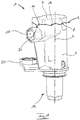
- Figure 1 shows a device housing 1 of a magnetic field sensor in a perspective side view.
- the device housing 1 has a first housing part 2, which is designed as a housing pot, and a second housing part 4, which closes the first housing part 2 and which is designed as a housing cover.
- the first housing part 2 and the second housing part 4 together form the device housing 1.
- both the first housing part 2 and the second housing part 4 are made of a plastic material and are preferably a plastic injection-molded component. Glass fibers can be added to the plastic material of the first housing part 2 and of the second housing part 4 to increase strength.
- the first housing part 2 and the second housing part 4 are joined in the direction of a longitudinal axis L of the device housing 1 and connected by means of a non-releasable joining connection 6.
- the first housing part 2 and the second housing part 4 each have a corresponding wave contour 8, 10.
- the wave contour 8 of the first housing part 2 is designed to fit precisely with the wave contour 10 of the second housing part 4.
- the wave contours 8, 10 are formed in the direction of the longitudinal axis L of the device housing 1. In addition, the wave contours 8, 10 are on a housing edge 12 of the first housing part 2 (see Figure 2 ) or on a housing edge 14 of the second housing part 4 (see Figure 11 ) educated.
- the wave contour 8 has a structure which can be referred to, for example, as a crown structure or a wave-shaped crown design.
- the wave contours 8, 10 form a joint wave contour 16.
- the joint wave contour 16 also forms a crown structure due to the wave contours 8, 10 in the form of a crown structure.
- the device housing 1 of the magnetic field sensor also has a cable inlet 18 on the first housing part 2 for the electrical connection of electronic components of the magnetic field sensor arranged in the device housing 1 with, for example, a tachograph.
- a connection cable to the tachograph is inserted through the cable inlet 18 into the device housing 1 and is electrically connected to a printed circuit board arranged in the device housing 1.
- the circuit board carries a sensor element, for example a Hall element.
- the sensor element and possibly an associated magnet arranged on the circuit board are arranged in a sensor head 19 of the magnetic field sensor, which magnetic field sensor can also be referred to as an inductive transmitter.
- Part of the first housing part 2 of the device housing 1, namely here a pot-shaped end section of the first housing part 2, is part of the sensor head 19.
- the first housing part 2 has a connection element 20 for attaching the magnetic field sensor to a motor vehicle, for example.
- the joint connection 6 is a pressure welded connection. In a special embodiment, it can in particular be an ultrasonic welded connection.
- the wave contour 8 of the first housing part 2 and the wave contour 10 of the second housing part 4 are pressure-welded to one another, in particular ultrasonically welded.
- a circumferential shoulder surface 17 forms on the first housing part 2 (see FIG Figure 4 ) a welding surface for connection to the second housing part 4.
- the joining wave contour 16 is thus the resulting wave contour of the joining connection 6 after the first housing part 2 and the second housing part 4 have been welded.
- the two parts, namely the first Housing part 2 and second housing part 4 no longer joining again without the previous separation remaining recognizable, since the saw cut leading through the joining wave contour 16 cannot be concealed.
- the joint connection is an adhesive connection and that the wave contour 8 of the first housing part 2 and the wave contour 10 of the second housing part 4 are glued to one another.
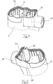
- the first housing part 2 has a plurality of housing material weakenings 22 aligned parallel to the longitudinal axis L of the device housing 1 (see, for example, FIG Figures 2 , 14th ).
- the housing material weakenings 22 are arranged in the area of the joint connection 6. They serve as predetermined breaking points, for example when attempting to open the device housing 2 by rotating the first housing part 2 and the second housing part 4 against each other.
- the housing material weakenings 22 are designed in the form of grooves.
- Figure 9 shows in a sectional view of the first housing part 2 that the housing material weaknesses 22 are arranged circumferentially on the inside of the first housing part 2.
- Figure 10 shows Figure 10 a notch-shaped cross-sectional formation 24 of the weakened housing material 22, that is to say the weakened housing material 22 is notch-shaped.
- the second housing part 4 has a joining contour 23 (see Figure 13 ) for pre-assembly of the second housing part 4 and the first housing part 2.
- An external stop surface 25 of the second housing part 4 serves as a stop for the first housing part 2 during pre-assembly.
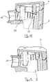
- the energy direction transmitter 27 forms an area of the second housing part 4, which area with the shoulder surface 17 of the first housing part 2 during ultrasonic welding of the first Housing part 2 and the second housing part 4 is welded. After the welding, there is a welding area 29 that runs around the device housing 1 and is part of both the first housing part 2 and the second housing part 4 (see FIG Figure 14 ).
- the joint connection 6 has a pin 26 aligned parallel to the longitudinal axis L of the device housing 1 and a corresponding pocket 28 receiving the pin 26.
- the pin 26 is on the second housing part 4 and the pocket 28 is on the first housing part 2 arranged.
- the pin 26 and the pocket 28 are pressure-welded to one another, in particular ultrasonically welded.
- the pin 26 is sword-shaped and the pocket 28 is box-shaped.
- the housing part namely here the first housing part 2 to which the pocket 28 is assigned, has a housing material weakening 30 all around the pocket 28 (see, for example, FIG Figure 7 ).
- This weakening of the housing material 30, which is designed in the form of a groove in this exemplary embodiment, serves as an additional predetermined breaking point, for example when attempting to open the device housing 1 forcibly.
- the housing material weakening 30 is preferably designed in the shape of a notch.
- the housing part namely here the second housing part 4, to which the pin 26 is assigned, has a housing material weakening 32 all around the pin 26 (see for example Figure 13 ).
- this weakened housing material 32 on the second housing part 4 is a groove. It is preferably designed in the shape of a notch.
- the plastic material of the first housing part 2 and of the second housing part 4 preferably breaks in a glass-like manner. Furthermore, the plastic material preferably has a discoloration that is discernible as a result of the destruction in the area of destruction in which it bursts or tears open or breaks open.
- the aim of preventing invisible opening of the device housing 1 can advantageously be achieved.
- the joining wave contour 16, which forms a crown structure, does not allow the first housing part 2 to be separated from the second housing part 4 with a flat and narrow (saw) cut in such a way that such a cut can be made when the first housing part 2 and the second housing part are joined again later 4 becomes unrecognizable.
- a manipulation attempt by opening the magnetic field sensor can thus be easily detected optically.
Landscapes
- Engineering & Computer Science (AREA)
- Mechanical Engineering (AREA)
- Physics & Mathematics (AREA)
- Condensed Matter Physics & Semiconductors (AREA)
- General Physics & Mathematics (AREA)
- Measuring Fluid Pressure (AREA)
- Transmission And Conversion Of Sensor Element Output (AREA)
Abstract
Description
- Die Erfindung bezieht sich auf einen Magnetfeldsensor mit einem zumindest ein erstes Gehäuseteil und ein das erste Gehäuseteil verschließendes zweites Gehäuseteil aufweisenden Gerätegehäuse, wobei das erste Gehäuseteil und das zweite Gehäuseteil in Richtung einer Längsachse des Gerätegehäuses gefügt und mittels einer nicht-lösbaren Fügeverbindung verbunden sind.
- Ein solcher Magnetfeldsensor ist zum Beispiel als sogenannter Geschwindigkeitsgeber oder Drehwertgeber für einen Fahrtschreiber in einem Kraftfahrzeug, insbesondere Nutzfahrzeug, bekannt. Der Magnetfeldsensor weist einen Sensorkopf auf und wird zum Beispiel in ein Getriebegehäuse eines Getriebes des Kraftfahrzeugs beispielsweise eingeschraubt oder zum Beispiel in der Nähe eines sich korrespondierend mit einer Fahrgeschwindigkeit des Kraftfahrzeugs drehenden Drehbauteils befestigt. Mittels des Sensorkopfes erfasst der Magnetfeldsensor eine Bewegung eines Getriebezahnrades des Getriebes bzw. des Drehbauteils. Die Bewegung des Getriebezahnrades ist ein Maß für die Geschwindigkeit des Kraftfahrzeugs. Ein Teil eines ersten Gehäuseteils eines Gerätegehäuses des Magnetfeldsensors ist Bestandteil des Sensorkopfes. Das erste Gehäuseteil wird von einem zweiten Gehäuseteil des Gerätegehäuses verschlossen, wobei das zweite Gehäuseteil Anschlusskontakte aufweist, mittels welchen der Magnetfeldsensor mit dem Fahrtschreiber des Kraftfahrzeugs verbunden wird. Zum Schutz von in dem Gerätegehäuse angeordneten Bauteilen des Magnetfeldsensors sowohl vor Umwelteinflüssen als auch vor unerlaubten äußeren Zugriffen sind das erste Gehäuseteil und das zweite Gehäuseteil mittels einer nicht-lösbaren Fügeverbindung verbunden. Aufgrund der erforderlichen hohen Zuverlässigkeit von mit dem Fahrtschreiber aufgezeichneten Daten ist es unter anderem von Bedeutung, eine Manipulation des Magnetfeldsensors und aus einer solchen Manipulation folgende Datenverfälschungen zu vermeiden.
- Aufgabe der Erfindung ist es, einen Magnetfeldsensor der eingangs genannten Art zu schaffen, der eine hohe Manipulationssicherheit aufweist.
- Diese Aufgabe wird erfindungsgemäß dadurch gelöst, dass das erste Gehäuseteil und das zweite Gehäuseteil jeweils eine korrespondierende Wellenkontur aufweisen, wobei die Wellenkonturen in Richtung der Längsachse des Gerätegehäuses und an einem Gehäuserand des ersten Gehäuseteils bzw. an einem Gehäuserand des zweiten Gehäuseteils ausgebildet sind und in der Fügeverbindung eine Fügewellenkontur bilden.
- Somit sind die Wellenkonturen in Fügerichtung, welche sich daraus ergibt, dass das erste Gehäuseteil und das zweite Gehäuseteil in Richtung der Längsachse des Gerätegehäuses gefügt sind, ausgebildet. Die Wellenkontur an dem ersten Gehäuseteil und die Wellenkontur an dem zweiten Gehäuseteil ergeben in der Fügeverbindung die Fügewellenkontur. Somit weist die Fügeverbindung die Fügewellenkontur auf. Insbesondere kann die Fügewellenkontur um das Gerätegehäuse des Magnetfeldsensors umlaufen, und zwar vorzugsweise an einer Außenseite des Gerätegehäuses. Die Wellenkontur an dem ersten Gehäuseteil und die Wellenkontur an dem zweiten Gehäuseteil bilden jeweils eine Kronenstruktur an dem jeweiligen Gehäuseteil. Entsprechend bildet auch die Fügewellenkontur eine Kronenstruktur. Zum Beispiel ein Aufsägen des Gerätegehäuses beispielsweise mit einem dünnen Sägeschnitt ist somit nicht möglich, ohne dauerhaft sichtbare Veränderungen am Gerätegehäuse zurückzulassen.
- Vorzugsweise können das erste Gehäuseteil und/oder das zweite Gehäuseteil jeweils ein Kunststoffbauteil sein, das heißt aus einem Kunststoffmaterial bestehen. Vorzugsweise kann das Kunststoffmaterial Glasfasern aufweisen, zum Beispiel einen Anteil von 30%.
- Von besonderem Vorteil ist bei dem erfindungsgemäßen Magnetfeldsensor das Vorsehen der korrespondierenden Wellenkonturen an dem Gehäuserand des ersten Gehäuseteils und an dem Gehäuserand des zweiten Gehäuseteils. Die sich daraus ergebende Fügewellenkontur in der Fügeverbindung hat zur Folge, dass ein unzulässiges Trennen von erstem Gehäuseteil und zweitem Gehäuseteil, welches Trennen zum Beispiel in manipulativer Absicht vorgenommen werden könnte, um an das Innere des Magnetfeldsensors zu gelangen, somit besonders zuverlässig erkennbar gemacht werden kann, da das Trennen nicht nur zu einem Öffnen des Gerätegehäuses, sondern auch zu einer Zerstörung der Fügewellenkontur und Bildung einer von der Fügewellenkontur abweichenden Trennlinie führt. Bei einem erneuten Fügen und Verbinden von erstem Gehäuseteil und zweitem Gehäuseteil bleibt mithin eine von der Fügewellenkontur abweichende Trennlinie sichtbar, wodurch die erfolgte Manipulation dauerhaft erkennbar bleibt.
- Man könnte sich zum Beispiel vorstellen, dass die Fügeverbindung eine Klebeverbindung ist. Hingegen ist es für eine besonders zuverlässige, dauerhaltbare und insbesondere auch in einer Großserienfertigung gut herstellbare Fügeverbindung von Vorteil, wenn gemäß einer Weiterbildung der Erfindung die Fügeverbindung eine Pressschweißverbindung ist. Vorzugsweise kann die Pressschweißverbindung eine Ultraschallschweißverbindung sein.
- Denkbar ist es beispielsweise, dass die Wellenkonturen des ersten und des zweiten Gehäuseteils in der Fügeverbindung und/oder beim Fügen lediglich einer Führung dienen. Hingegen ist es für eine besonders sichere Verbindung des ersten und des zweiten Gehäuseteils sowie für einen weiter erhöhten Manipulationsschutz von besonderem Vorteil, wenn gemäß einer Weiterbildung der Erfindung die Wellenkontur des ersten Gehäuseteils und die Wellenkontur des zweiten Gehäuseteils miteinander pressverschweißt, vorzugsweise ultraschallverschweißt, sind.
- Gemäß einer anderen vorteilhaften Weiterbildung der Erfindung sind die Wellenkonturen des ersten Gehäuseteils und des zweiten Gehäuseteils jeweils unregelmäßig ausgebildet. Die unregelmäßige Ausbildung der Wellenkonturen bedeutet, dass diese zum Beispiel nicht sinuskurvenförmig ausgebildet sind. Von besonderem Vorteil ist es zudem, wenn in Querrichtung der Längsachse des Gerätegehäuses auf gegenüberliegenden Seiten der Längsachse angeordnete Wellenkonturabschnitte der Wellenkontur nicht deckungsgleich sind.
- Gemäß einer vorteilhaften Weiterbildung der Erfindung weisen die Wellenkonturen jeweils untereinander verschiedene Wellenberghöhen auf. Mit einer solchen Ausgestaltung wird der Manipulationsschutz des Magnetfeldsensors vorteilhaft zusätzlich erhöht.
- Gemäß einer anderen vorteilhaften Weiterbildung der Erfindung ist das erste Gehäuseteil und/oder das zweite Gehäuseteil jeweils ein Spritzgussbauteil, und eine Formtrennkante des jeweiligen Gehäuseteils folgt der Wellenkontur des jeweiligen Gehäuseteils. Somit ist an dem Gehäuseteil auch keine von der Wellenkontur abweichende, sichtbare Formtrennkante vorhanden, entlang welcher ggf. ein nur schwer zu entdeckendes Auftrennen des Gerätegehäuses in manipulativer Absicht erfolgen könnte.
- Eine andere vorteilhafte Weiterbildung der Erfindung zeichnet sich dadurch aus, dass das erste Gehäuseteil und/oder das zweite Gehäuseteil eine Mehrzahl von parallel zu der Längsachse des Gerätegehäuses ausgerichteten Gehäusematerialschwächungen aufweist, wobei die Gehäusematerialschwächungen im Bereich der Fügeverbindung angeordnet sind. Somit sind nach dieser Weiterbildung der Erfindung mindestens zwei Gehäusematerialschwächungen an dem Gerätegehäuse vorhanden. Die Gehäusematerialschwächungen können zum Beispiel als Nuten in dem Gerätegehäuse ausgebildet sein. Dass die Gehäusematerialschwächungen im Bereich der Fügeverbindung angeordnet sind bedeutet, dass sich die Gehäusematerialschwächungen in der Fügeverbindung befinden oder angrenzend an die Fügeverbindung angeordnet sind. Die Gehäusematerialschwächungen wirken als Soll-Bruchstellen, sodass zum Beispiel ein Versuch, die Fügeverbindung durch Verdrehen der Gehäuseteile gegeneinander zu öffnen, zu einem Aufbrechen und somit Zerstören des Gerätegehäuses führt.
- Einer anderen vorteilhaften Weiterbildung der Erfindung gemäß weist die Fügeverbindung einen parallel zu der Längsachse des Gerätegehäuses ausgerichteten Zapfen und eine den Zapfen aufnehmende korrespondierende Tasche auf, wobei der Zapfen an einem der beiden Gehäuseteile und die Tasche an dem anderen der beiden Gehäuseteile angeordnet ist. Damit ist, vorzugsweise im Inneren des Gerätegehäuses, vorteilhaft eine zusätzliche Verbindung zwischen den beiden Gehäuseteilen geschaffen. Der Zapfen, der auch als Schwert oder Dorn bezeichnet werden könnte, ist in Fügerichtung der Fügeverbindung ausgerichtet. Die Tasche kann zum Beispiel kastenförmig ausgebildet sein. Der Zapfen ist an dem ersten Gehäuseteil oder an dem zweiten Gehäuseteil und die Tasche umgekehrt an dem zweiten Gehäuseteil bzw. dem ersten Gehäuseteil angeordnet.
- Es wäre zum Beispiel denkbar, dass Zapfen und Tasche nur zur Führung in der Fügeverbindung angeordnet sind. Hingegen ist es von besonderem Vorteil, wenn gemäß einer Weiterbildung der Erfindung der Zapfen und die Tasche miteinander pressverschweißt sind. Vorzugsweise sind der Zapfen und die Tasche miteinander ultraschallverschweißt. Aufgrund der Schweißverbindung von Zapfen und Tasche ist ein Auseinanderziehen oder Aufbrechen der Verbindung nahezu unmöglich.
- Einer anderen vorteilhaften Weiterbildung der Erfindung entsprechend weist das Gehäuseteil, dem die Tasche zugeordnet ist, umlaufend um die Tasche eine Gehäusematerialschwächung auf. Die Gehäusematerialschwächung kann zum Beispiel eine Nut sein. Vorzugsweise ist die Gehäusematerialschwächung kerbenförmig ausgebildet. Die Gehäusematerialschwächung bildet eine Soll-Bruchstelle zwischen Tasche und Gehäuseteil.
- Einer anderen vorteilhaften Weiterbildung der Erfindung gemäß weist das Gehäuseteil, dem der Zapfen zugeordnet ist, umlaufend um den Zapfen eine Gehäusematerialschwächung, die zum Beispiel als Nut ausgebildet sein kann, auf. Die Gehäusematerialschwächung ist vorzugsweise kerbenförmig ausgebildet. Die Gehäusematerialschwächung bildet eine Soll-Bruchstelle zwischen Zapfen und Gehäuseteil.
- Ausführungsbeispiele der Erfindung sind in der Zeichnung skizzenhaft und schematisiert dargestellt und werden im Folgenden näher beschrieben. Es zeigen:
- Figur 1
- ein Gerätegehäuse eines Magnetfeldsensors in einer perspektivischen Ansicht,
- Figur 2
- einen Ausschnitt eines ersten Gehäuseteils des Gerätegehäuses nach
Figur 1 in einer perspektivischen Ansicht, - Figur 3
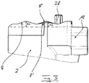
- eine Seitenansicht eines Ausschnitts des ersten Gehäuseteils nach
Figur 2 , - Figur 4
- einen Ausschnitt des ersten Gehäuseteils nach
Figur 2 in einer perspektivischen Ansicht, - Figur 5
- einen Ausschnitt des ersten Gehäuseteils nach
Figur 2 in einer weiteren perspektivischen Ansicht, - Figur 6
- einen Ausschnitt des ersten Gehäuseteils nach
Figur 2 in einer Schnittansicht, - Figur 7
- einen Ausschnitt des ersten Gehäuseteils nach
Figur 2 in einer weiteren Schnittansicht, - Figur 8
- einen Ausschnitt des ersten Gehäuseteils nach
Figur 2 in einer weiteren perspektivischen Ansicht, - Figur 9
- einen Ausschnitt des ersten Gehäuseteils nach
Figur 2 in einer weiteren Schnittansicht, - Figur 10
- einen vergrößerten Ausschnitt A der Schnittansicht nach
Figur 9 des ersten Gehäuseteils, - Figur 11
- ein zweites Gehäuseteil des Gerätegehäuses nach
Figur 1 in einer perspektivischen Ansicht, - Figur 12
- das zweite Gehäuseteil nach
Figur 11 in einer weiteren perspektivischen Ansicht, - Figur 13
- eine Schnittansicht des zweiten Gehäuseteils nach
Figur 11 , - Figur 14
- eine Schnittansicht eines Ausschnitts des Gerätegehäuses nach
Figur 1 , - Figur 15
- eine perspektivische Schnittansicht eines Ausschnitts des Gerätegehäuses nach
Figur 1 und - Figur 16
- eine weitere perspektivische Schnittansicht eines Ausschnitts des Gerätegehäuses nach
Figur 1 . - Sich jeweils entsprechende Elemente sind in allen Figuren mit gleichen Bezugszeichen versehen.
-
Figur 1 zeigt in einer perspektivischen Seitenansicht ein Gerätegehäuse 1 eines Magnetfeldsensors. Das Gerätegehäuse 1 weist ein erstes Gehäuseteil 2, das als Gehäusetopf ausgebildet ist, und ein das erste Gehäuseteil 2 verschließendes zweites Gehäuseteil 4, das als Gehäusedeckel ausgebildet ist, auf. In diesem Ausführungsbeispiel bilden das erste Gehäuseteil 2 und das zweite Gehäuseteil 4 gemeinsam das Gerätegehäuse 1. - Sowohl das erste Gehäuseteil 2 als auch das zweite Gehäuseteil 4 besteht in diesem Ausführungsbeispiel aus einem Kunststoffmaterial und ist vorzugsweise ein Kunststoffspritzgussbauteil. Dem Kunststoffmaterial des ersten Gehäuseteils 2 sowie des zweiten Gehäuseteils 4 können Glasfasern zur Festigkeitserhöhung beigefügt sein.
- Das erste Gehäuseteil 2 und das zweite Gehäuseteil 4 sind in Richtung einer Längsachse L des Gerätegehäuses 1 gefügt und mittels einer nicht-lösbaren Fügeverbindung 6 verbunden. Das erste Gehäuseteil 2 und das zweite Gehäuseteil 4 weisen jeweils eine korrespondierende Wellenkontur 8, 10 auf. Die Wellenkontur 8 des ersten Gehäuseteils 2 ist passgenau zu der Wellenkontur 10 des zweiten Gehäuseteils 4 ausgebildet.
- Die Wellenkonturen 8, 10 sind in Richtung der Längsachse L des Gerätegehäuses 1 ausgebildet. Zudem sind die Wellenkonturen 8, 10 an einem Gehäuserand 12 des ersten Gehäuseteils 2 (siehe
Figur 2 ) bzw. an einem Gehäuserand 14 des zweiten Gehäuseteils 4 (sieheFigur 11 ) ausgebildet. - Beispielsweise aus
Figur 2 wird besonders deutlich, dass die Wellenkontur 8 eine Struktur aufweist, die zum Beispiel als Kronenstruktur oder wellenförmiges Kronendesign bezeichnet werden kann. In der Fügeverbindung 6 bilden die Wellenkonturen 8, 10 eine Fügewellenkontur 16. Auch die Fügewellenkontur 16 bildet aufgrund der jeweils kronenstrukturförmigen Wellenkonturen 8, 10 eine Kronenstruktur. - Das Gerätegehäuse 1 des Magnetfeldsensors weist in diesem Ausführungsbeispiel zudem an dem ersten Gehäuseteil 2 einen Kabeleingang 18 zur elektrischen Verbindung von in dem Gerätegehäuse 1 angeordneten elektronischen Bauelementen des Magnetfeldsensors mit zum Beispiel einem Fahrtschreiber auf. Beispielsweise ist ein Verbindungskabel zu dem Fahrtschreiber durch den Kabeleingang 18 in das Gerätegehäuse 1 eingeführt und mit einer in dem Gerätegehäuse 1 angeordneten Leiterplatte elektrisch verbunden.
- Die Leiterplatte trägt ein Sensorelement, zum Beispiel ein Hall-Element. Das Sensorelement und gegebenenfalls ein zugehöriger, an der Leiterplatte angeordneter Magnet ist in einem Sensorkopf 19 des Magnetfeldsensors, welcher Magnetfeldsensor auch als Induktivgeber bezeichnet werden kann, angeordnet. Ein Teil des ersten Gehäuseteils 2 des Gerätegehäuses 1, nämlich hier ein topfförmiger Endabschnitt des ersten Gehäuseteils 2, ist Bestandteil des Sensorkopfs 19. Weiterhin weist das erste Gehäuseteil 2 ein Anschlusselement 20 zur Befestigung des Magnetfeldsensors zum Beispiel an einem Kraftfahrzeug auf.
- In dem hier gezeigten Ausführungsbeispiel ist die Fügeverbindung 6 eine Pressschweißverbindung. Sie kann in einem speziellen Ausführungsbeispiel insbesondere eine Ultraschallschweißverbindung sein. Die Wellenkontur 8 des ersten Gehäuseteils 2 und die Wellenkontur 10 des zweiten Gehäuseteils 4 sind miteinander pressverschweißt, insbesondere ultraschallverschweißt.
- Zum Beispiel bildet hierfür an dem ersten Gehäuseteil 2 eine umlaufende Absatzfläche 17 (siehe
Figur 4 ) eine Schweißfläche zur Verbindung mit dem zweiten Gehäuseteil 4. Die Fügewellenkontur 16 ist somit die resultierende Wellenkontur der Fügeverbindung 6 nach dem Verschweißen von erstem Gehäuseteil 2 und zweitem Gehäuseteil 4. Zum Beispiel mittels eines geraden Sägeschnittes aufgetrennt, lassen sich die beiden Teile, nämlich erstes Gehäuseteil 2 und zweites Gehäuseteil 4, nicht mehr erneut Fügen, ohne dass das vorherige Auftrennen weiterhin erkennbar bleibt, da sich der durch die Fügewellenkontur 16 führende Sägeschnitt nicht kaschieren lässt. - Denkbar ist es zum Beispiel auch, dass in einem anderen Ausführungsbeispiel die Fügeverbindung eine Klebeverbindung ist, und dass die Wellenkontur 8 des ersten Gehäuseteils 2 und die Wellenkontur 10 des zweiten Gehäuseteils 4 miteinander verklebt sind.
- Aus
Figuren 1 bis 8 und11 bis 16 wird deutlich, dass die Wellenkonturen 8, 10 des ersten Gehäuseteils 2 und des zweiten Gehäuseteils 4 jeweils unregelmäßig ausgebildet sind. Zum BeispielFigur 3 zeigt zudem deutlich, dass die Wellenkonturen, hier gezeigt anhand der Wellenkontur 8 des ersten Gehäuseteils 2, untereinander verschiedene Wellenberghöhen h1, h2 aufweisen. - Ferner sind, wie insbesondere aus der in
Figur 3 gezeigten Seitenansicht ersichtlich ist, in Querrichtung der Längsachse L des Gerätegehäuses 1 auf gegenüberliegenden Seiten der Längsachse L angeordnete Wellenkonturabschnitte 8', 8" der Wellenkontur 8 nicht deckungsgleich. Außerdem befindet sich im Bereich des Kabeleingangs 18 an dem ersten Gehäuseteil 2 ein Wellental 21, welches keinerlei Überdeckung mit einem anderen Konturabschnitt zulässt (siehe zum BeispielFigur 1 ). - Das erste Gehäuseteil 2 weist eine Mehrzahl von parallel zu der Längsachse L des Gerätegehäuses 1 ausgerichteten Gehäusematerialschwächungen 22 auf (siehe zum Beispiel
Figuren 2 ,14 ). Die Gehäusematerialschwächungen 22 sind im Bereich der Fügeverbindung 6 angeordnet. Sie dienen als Soll-Bruchstellen zum Beispiel bei einem Versuch, das Gerätegehäuse 2 durch Verdrehen des ersten Gehäuseteils 2 und des zweiten Gehäuseteils 4 gegeneinander zu öffnen. In dem hier gezeigten Ausführungsbeispiel sind die Gehäusematerialschwächungen 22 nutförmig ausgebildet. -
Figur 9 zeigt in einer Schnittansicht des ersten Gehäuseteils 2, dass die Gehäusematerialschwächungen 22 umlaufend an der Innenseite des ersten Gehäuseteils 2 angeordnet sind. In einem vergrößerten Ausschnitt A ausFigur 9 zeigtFigur 10 eine kerbenförmige Querschnittsausbildung 24 der Gehäusematerialschwächungen 22, das heißt die Gehäusematerialschwächungen 22 sind kerbenförmig ausgebildet. - Das zweite Gehäuseteil 4 weist eine Fügekontur 23 (siehe
Figur 13 ) zur Vormontage von zweitem Gehäuseteil 4 und erstem Gehäuseteil 2 auf. Eine außenliegende Anschlagfläche 25 des zweiten Gehäuseteils 4 dient als Anschlag für das erste Gehäuseteil 2 bei der Vormontage. Ein zwischen Fügekontur 23 und Anschlagfläche 25 angeordneter sogenannter Energierichtungsgeber 27 des zweiten Gehäuseteils 4 korrespondiert mit der Absatzfläche 17 des ersten Gehäuseteils 2. Der Energierichtungsgeber 27 bildet einen Bereich des zweiten Gehäuseteils 4, welcher Bereich mit der Absatzfläche 17 des ersten Gehäuseteils 2 beim Ultraschallverschweißen von erstem Gehäuseteil 2 und zweitem Gehäuseteil 4 verschweißt wird. Nach dem Verschweißen liegt ein um das Gerätegehäuse 1 umlaufender Verschweißungsbereich 29 vor, der sowohl Bestandteil des ersten Gehäuseteils 2 als auch des zweiten Gehäuseteils 4 ist (sieheFigur 14 ). - Zum Beispiel in
Figur 14 ist dargestellt, dass die Fügeverbindung 6 einen parallel zu der Längsachse L des Gerätegehäuses 1 ausgerichteten Zapfen 26 und eine den Zapfen 26 aufnehmende korrespondierende Tasche 28 aufweist. Dabei ist der Zapfen 26 an dem zweiten Gehäuseteil 4 und die Tasche 28 an dem ersten Gehäuseteil 2 angeordnet. Der Zapfen 26 und die Tasche 28 sind in diesem Ausführungsbeispiel miteinander pressverschweißt, insbesondere ultraschallverschweißt. Der Zapfen 26 ist schwertförmig und die Tasche 28 kastenförmig ausgebildet. - Das Gehäuseteil, nämlich hier das erste Gehäuseteil 2, dem die Tasche 28 zugeordnet ist, weist umlaufend um die Tasche 28 eine Gehäusematerialschwächung 30 auf (siehe zum Beispiel
Figur 7 ). Diese Gehäusematerialschwächung 30, die in diesem Ausführungsbeispiel nutförmig ausgebildet ist, dient als zusätzliche Soll-Bruchstelle zum Beispiel bei einem Versuch, das Gerätegehäuse 1 gewaltsam zu öffnen. Die Gehäusematerialschwächung 30 ist vorzugsweise kerbenförmig ausgebildet. - Weiterhin weist das Gehäuseteil, nämlich hier das zweite Gehäuseteil 4, dem der Zapfen 26 zugeordnet ist, umlaufend um den Zapfen 26 eine Gehäusematerialschwächung 32 auf (siehe zum Beispiel
Figur 13 ). In dem hier gezeigten Ausführungsbeispiel ist diese Gehäusematerialschwächung 32 an dem zweiten Gehäuseteil 4 eine Nut. Vorzugsweise ist sie kerbenförmig ausgebildet. - Im Falle eines Versuchs, beispielsweise mittels Walkens oder Aufhebelns die Schweißverbindung zwischen Zapfen 26 und Tasche 28 zu schwächen und zu zerstören, platzen oder reißen oder brechen die um den Zapfen 26 umlaufende Gehäusematerialschwächung 32 an dem zweiten Gehäuseteil 4 und/oder die um die Tasche 28 umlaufende Gehäusematerialschwächung 30 an dem ersten Gehäuseteil 2 auf. Damit wird ein solcher Manipulationsversuch an dem Magnetfeldsensor eindeutig sichtbar. Entsprechendes gilt auch für ein Aufplatzen oder Aufreißen oder Aufbrechen der oben beschriebenen, parallel zu der Längsachse L des Gerätegehäuses 1 ausgerichteten und im Bereich der Fügeverbindung 6 angeordneten Gehäusematerialschwächungen 22.
- Vorzugsweise bricht das Kunststoffmaterial des ersten Gehäuseteils 2 und des zweiten Gehäuseteils 4 glasartig. Weiter vorzugsweise weist das Kunststoffmaterial im Zerstörungsbereich, in dem es aufplatzt oder aufreißt oder aufbricht, eine erkennbare, sich durch die Zerstörung ergebende Verfärbung auf.
- Mit der Erfindung kann vorteilhaft das Ziel erreicht werden, ein nicht-sichtbares Öffnen des Gerätegehäuses 1 zu verhindern. Die eine Kronenstruktur bildende Fügewellenkontur 16 lässt es nicht zu, mit einem ebenen und schmalen (Säge-)Schnitt das erste Gehäuseteil 2 von dem zweiten Gehäuseteil 4 derart zu trennen, dass ein solcher Schnitt bei einem späteren erneuten Fügen von erstem Gehäuseteil 2 und zweitem Gehäuseteil 4 unerkennbar wird. Ein Manipulationsversuch durch Öffnen des Magnetfeldsensors ist dadurch optisch einfach zu detektieren.
Claims (11)
- Magnetfeldsensor mit einem zumindest ein erstes Gehäuseteil (2) und ein das erste Gehäuseteil (2) verschließendes zweites Gehäuseteil (4) aufweisenden Gerätegehäuse (1), wobei das erste Gehäuseteil (2) und das zweite Gehäuseteil (4) in Richtung einer Längsachse (L) des Gerätegehäuses (1) gefügt und mittels einer nicht-lösbaren Fügeverbindung (6) verbunden sind, dadurch gekennzeichnet, dass das erste Gehäuseteil (2) und das zweite Gehäuseteil (4) jeweils eine korrespondierende Wellenkontur (8, 10) aufweisen, wobei die Wellenkonturen (8, 10) in Richtung der Längsachse (L) des Gerätegehäuses (1) und an einem Gehäuserand (12) des ersten Gehäuseteils (2) bzw. an einem Gehäuserand (14) des zweiten Gehäuseteils (4) ausgebildet sind und in der Fügeverbindung (6) eine Fügewellenkontur (16) bilden.
- Magnetfeldsensor nach Anspruch 1, dadurch gekennzeichnet, dass die Fügeverbindung (6) eine Pressschweißverbindung ist.
- Magnetfeldsensor nach Anspruch 1 oder 2, dadurch gekennzeichnet, dass die Wellenkontur (8) des ersten Gehäuseteils (2) und die Wellenkontur (10) des zweiten Gehäuseteils (4) miteinander pressverschweißt sind.
- Magnetfeldsensor nach einem der vorhergehenden Ansprüche, dadurch gekennzeichnet, dass die Wellenkonturen (8, 10) des ersten Gehäuseteils (2) und des zweiten Gehäuseteils (4) jeweils unregelmäßig ausgebildet sind.
- Magnetfeldsensor nach Anspruch 4, dadurch gekennzeichnet, dass die Wellenkonturen (8, 10) jeweils untereinander verschiedene Wellenberghöhen (h1, h2) aufweisen.
- Magnetfeldsensor nach einem der vorhergehenden Ansprüche, dadurch gekennzeichnet, dass das erste Gehäuseteil (2) und/oder das zweite Gehäuseteil (4) jeweils ein Spritzgussbauteil ist und dass eine Formtrennkante des jeweiligen Gehäuseteils (2, 4) der Wellenkontur (8, 10) des jeweiligen Gehäuseteils (2, 4) folgt.
- Magnetfeldsensor nach einem der vorhergehenden Ansprüche, dadurch gekennzeichnet, dass das erste Gehäuseteil (2) und/oder das zweite Gehäuseteil (4) eine Mehrzahl von parallel zu der Längsachse (L) des Gerätegehäuses (1) ausgerichteten Gehäusematerialschwächungen (22) aufweist, wobei die Gehäusematerialschwächungen (22) im Bereich der Fügeverbindung (6) angeordnet sind.
- Magnetfeldsensor nach einem der vorhergehenden Ansprüche, dadurch gekennzeichnet, dass die Fügeverbindung (6) einen parallel zu der Längsachse (L) des Gerätegehäuses (1) ausgerichteten Zapfen (26) und eine den Zapfen (26) aufnehmende korrespondierende Tasche (28) aufweist, wobei der Zapfen (26) an einem der beiden Gehäuseteile (4) und die Tasche (28) an dem anderen der beiden Gehäuseteile (2) angeordnet ist.
- Magnetfeldsensor nach Anspruch 8, dadurch gekennzeichnet, dass der Zapfen (26) und die Tasche (28) miteinander pressverschweißt sind.
- Magnetfeldsensor nach Anspruch 8 oder 9, dadurch gekennzeichnet, dass das Gehäuseteil (2), dem die Tasche (28) zugeordnet ist, umlaufend um die Tasche (28) eine Gehäusematerialschwächung (30) aufweist.
- Magnetfeldsensor nach einem der Ansprüche 8 bis 10, dadurch gekennzeichnet, dass das Gehäuseteil (4), dem der Zapfen (26) zugeordnet ist, umlaufend um den Zapfen (26) eine Gehäusematerialschwächung (32) aufweist.
Applications Claiming Priority (1)
| Application Number | Priority Date | Filing Date | Title |
|---|---|---|---|
| DE102020201959.2A DE102020201959B4 (de) | 2020-02-17 | 2020-02-17 | Magnetfeldsensor mit einem Gerätegehäuse |
Publications (2)
| Publication Number | Publication Date |
|---|---|
| EP3865829A1 true EP3865829A1 (de) | 2021-08-18 |
| EP3865829B1 EP3865829B1 (de) | 2024-08-14 |
Family
ID=74184353
Family Applications (1)
| Application Number | Title | Priority Date | Filing Date |
|---|---|---|---|
| EP20216283.0A Active EP3865829B1 (de) | 2020-02-17 | 2020-12-22 | Magnetfeldsensor mit einem gerätegehäuse |
Country Status (2)
| Country | Link |
|---|---|
| EP (1) | EP3865829B1 (de) |
| DE (1) | DE102020201959B4 (de) |
Families Citing this family (1)
| Publication number | Priority date | Publication date | Assignee | Title |
|---|---|---|---|---|
| DE102020202668B4 (de) * | 2020-03-02 | 2021-09-23 | Continental Automotive Gmbh | Magnetfeldsensor mit einer Markierung und Verfahren zur Herstellung eines Magnetfeldsensors |
Citations (6)
| Publication number | Priority date | Publication date | Assignee | Title |
|---|---|---|---|---|
| DE29716262U1 (de) * | 1997-09-10 | 1997-12-18 | S + R Kunststofftechnik GmbH, 35394 Gießen | Kunststoffdose |
| GB2352443A (en) * | 1999-07-23 | 2001-01-31 | Rpc Containers Ltd | A container |
| US20030189047A1 (en) * | 2000-07-19 | 2003-10-09 | Mchutchinson Roy Neil | Tamper proof hinged lid container |
| US20190012892A1 (en) * | 2014-07-25 | 2019-01-10 | 1010210 B.C. Ltd. | Magnetic field sensor for use in a security alarm system |
| EP3441778A1 (de) * | 2017-08-07 | 2019-02-13 | Continental Automotive GmbH | Magnetfeldsensor |
| EP3557552A1 (de) * | 2018-04-16 | 2019-10-23 | Tyco Fire & Security GmbH | Verfahren und vorrichtung zur omnidirektionalen und sabotagesicheren manipulationsdetektion |
Family Cites Families (3)
| Publication number | Priority date | Publication date | Assignee | Title |
|---|---|---|---|---|
| DE10134646A1 (de) | 2001-07-17 | 2003-02-06 | Bosch Gmbh Robert | Sensorelement |
| DE102007051579A1 (de) | 2007-10-29 | 2009-05-20 | Andreas Siemes | Stromwandler für die Messung und den Schutz in Hoch- oder Mittelspannungsnetzen |
| DE102011081638A1 (de) | 2011-08-26 | 2013-02-28 | Zf Friedrichshafen Ag | Gehäuseteil für ein Gehäuse eines Sensors für ein Fahrzeuggetriebe, Gehäuse für einen Sensor für ein Fahrzeuggetriebe, Sensor für ein Fahrzeuggetriebe und Verfahren zum Herstellen eines Sensors für ein Fahrzeuggetriebe |
-
2020
- 2020-02-17 DE DE102020201959.2A patent/DE102020201959B4/de active Active
- 2020-12-22 EP EP20216283.0A patent/EP3865829B1/de active Active
Patent Citations (6)
| Publication number | Priority date | Publication date | Assignee | Title |
|---|---|---|---|---|
| DE29716262U1 (de) * | 1997-09-10 | 1997-12-18 | S + R Kunststofftechnik GmbH, 35394 Gießen | Kunststoffdose |
| GB2352443A (en) * | 1999-07-23 | 2001-01-31 | Rpc Containers Ltd | A container |
| US20030189047A1 (en) * | 2000-07-19 | 2003-10-09 | Mchutchinson Roy Neil | Tamper proof hinged lid container |
| US20190012892A1 (en) * | 2014-07-25 | 2019-01-10 | 1010210 B.C. Ltd. | Magnetic field sensor for use in a security alarm system |
| EP3441778A1 (de) * | 2017-08-07 | 2019-02-13 | Continental Automotive GmbH | Magnetfeldsensor |
| EP3557552A1 (de) * | 2018-04-16 | 2019-10-23 | Tyco Fire & Security GmbH | Verfahren und vorrichtung zur omnidirektionalen und sabotagesicheren manipulationsdetektion |
Also Published As
| Publication number | Publication date |
|---|---|
| EP3865829B1 (de) | 2024-08-14 |
| DE102020201959A1 (de) | 2021-08-19 |
| DE102020201959B4 (de) | 2021-10-28 |
Similar Documents
| Publication | Publication Date | Title |
|---|---|---|
| DE102013014456B4 (de) | Betätiger eines Sicherheitsschalters sowie Sicherheitsschalter mit einem solchen Betätiger | |
| EP2718140B1 (de) | Verriegelungsvorrichtung für elektrische ladekabel oder klappen | |
| EP2180453B1 (de) | Sicherheitsmaterial mit einem bahnartigen Gewirk | |
| WO1994008632A1 (de) | Sterilisierbehälter für chirurgische instrumente oder dergleichen | |
| EP4242616B1 (de) | Drehmomentsensorvorrichtung, flussleiteranordnung und flussleiter | |
| DE102007050258A1 (de) | Ringmagnet für eine Drehmoment- oder Drehwinkelsensoranordnung | |
| DE102020201960B4 (de) | Magnetfeldsensor mit einem Gerätegehäuse | |
| EP3441778B1 (de) | Magnetfeldsensor | |
| EP3847332B1 (de) | Schutzvorrichtung für einen türflügel für ein fahrzeug und türvorrichtung für ein fahrzeug | |
| EP3865829B1 (de) | Magnetfeldsensor mit einem gerätegehäuse | |
| EP3859351B1 (de) | Schutzhülse für einen drehzahlsensor und drehzahlsensor mit schutzhülse | |
| EP4483083B1 (de) | Vorrichtung der fluidtechnik | |
| DE102008014985A1 (de) | Magnetbaugruppe für eine Drehmoment- und/oder Drehwinkelsensoranordnung und Herstellungsverfahren | |
| DE112010003693T5 (de) | Sicherheitsschalter | |
| CH682140A5 (de) | ||
| EP1715498A1 (de) | Schalter, insbesondere Lenkstockschalter | |
| DE102020202668B4 (de) | Magnetfeldsensor mit einer Markierung und Verfahren zur Herstellung eines Magnetfeldsensors | |
| EP3474305B1 (de) | Sicherheitsschalter | |
| WO2016107683A1 (de) | Versatzerfassung zwischen gefügten bauteilen | |
| EP3767304B1 (de) | Magnetfeldsensor | |
| EP3835728B1 (de) | Magnetfeldsensor | |
| DE102021212793A1 (de) | Detektionseinrichtung zum Erfassen einer Überschreitung eines vorgegebenen maximalen Lenkdrehwinkels, Lenkvorrichtung mit einer solchen Detektionseinrichtung, Steer-by-Wire Lenksystem mit einer solchen Lenkvorrichtung, sowie Verfahren zum Erfassen einer Überschreitung eines vorgegebenen maximalen Lenkdrehwinkels | |
| DE102019203433B4 (de) | Anordnung eines Fahrzeugteils in einem Fahrzeug und Fahrzeugteil für ein Fahrzeug | |
| DE102004021032B4 (de) | Induktiver Drehzahlgeber | |
| EP4438508A1 (de) | Verpackungsbehälter |
Legal Events
| Date | Code | Title | Description |
|---|---|---|---|
| PUAI | Public reference made under article 153(3) epc to a published international application that has entered the european phase |
Free format text: ORIGINAL CODE: 0009012 |
|
| STAA | Information on the status of an ep patent application or granted ep patent |
Free format text: STATUS: THE APPLICATION HAS BEEN PUBLISHED |
|
| AK | Designated contracting states |
Kind code of ref document: A1 Designated state(s): AL AT BE BG CH CY CZ DE DK EE ES FI FR GB GR HR HU IE IS IT LI LT LU LV MC MK MT NL NO PL PT RO RS SE SI SK SM TR |
|
| STAA | Information on the status of an ep patent application or granted ep patent |
Free format text: STATUS: REQUEST FOR EXAMINATION WAS MADE |
|
| 17P | Request for examination filed |
Effective date: 20220218 |
|
| RBV | Designated contracting states (corrected) |
Designated state(s): AL AT BE BG CH CY CZ DE DK EE ES FI FR GB GR HR HU IE IS IT LI LT LU LV MC MK MT NL NO PL PT RO RS SE SI SK SM TR |
|
| RAP1 | Party data changed (applicant data changed or rights of an application transferred) |
Owner name: CONTINENTAL AUTOMOTIVE TECHNOLOGIES GMBH |
|
| RAP3 | Party data changed (applicant data changed or rights of an application transferred) |
Owner name: CONTINENTAL AUTOMOTIVE TECHNOLOGIES GMBH |
|
| GRAP | Despatch of communication of intention to grant a patent |
Free format text: ORIGINAL CODE: EPIDOSNIGR1 |
|
| STAA | Information on the status of an ep patent application or granted ep patent |
Free format text: STATUS: GRANT OF PATENT IS INTENDED |
|
| INTG | Intention to grant announced |
Effective date: 20240507 |
|
| RIN1 | Information on inventor provided before grant (corrected) |
Inventor name: FROSCH, KARL Inventor name: HUG, KLAUS Inventor name: WAHLER, TORSTEN |
|
| GRAS | Grant fee paid |
Free format text: ORIGINAL CODE: EPIDOSNIGR3 |
|
| GRAA | (expected) grant |
Free format text: ORIGINAL CODE: 0009210 |
|
| STAA | Information on the status of an ep patent application or granted ep patent |
Free format text: STATUS: THE PATENT HAS BEEN GRANTED |
|
| P01 | Opt-out of the competence of the unified patent court (upc) registered |
Free format text: CASE NUMBER: APP_34186/2024 Effective date: 20240607 |
|
| AK | Designated contracting states |
Kind code of ref document: B1 Designated state(s): AL AT BE BG CH CY CZ DE DK EE ES FI FR GB GR HR HU IE IS IT LI LT LU LV MC MK MT NL NO PL PT RO RS SE SI SK SM TR |
|
| REG | Reference to a national code |
Ref country code: GB Ref legal event code: FG4D Free format text: NOT ENGLISH |
|
| REG | Reference to a national code |
Ref country code: CH Ref legal event code: EP |
|
| REG | Reference to a national code |
Ref country code: DE Ref legal event code: R096 Ref document number: 502020008860 Country of ref document: DE |
|
| REG | Reference to a national code |
Ref country code: IE Ref legal event code: FG4D Free format text: LANGUAGE OF EP DOCUMENT: GERMAN |
|
| REG | Reference to a national code |
Ref country code: LT Ref legal event code: MG9D |
|
| REG | Reference to a national code |
Ref country code: NL Ref legal event code: MP Effective date: 20240814 |
|
| PGFP | Annual fee paid to national office [announced via postgrant information from national office to epo] |
Ref country code: DE Payment date: 20241231 Year of fee payment: 5 |
|
| PG25 | Lapsed in a contracting state [announced via postgrant information from national office to epo] |
Ref country code: NO Free format text: LAPSE BECAUSE OF FAILURE TO SUBMIT A TRANSLATION OF THE DESCRIPTION OR TO PAY THE FEE WITHIN THE PRESCRIBED TIME-LIMIT Effective date: 20241114 |
|
| PG25 | Lapsed in a contracting state [announced via postgrant information from national office to epo] |
Ref country code: NL Free format text: LAPSE BECAUSE OF FAILURE TO SUBMIT A TRANSLATION OF THE DESCRIPTION OR TO PAY THE FEE WITHIN THE PRESCRIBED TIME-LIMIT Effective date: 20240814 Ref country code: GR Free format text: LAPSE BECAUSE OF FAILURE TO SUBMIT A TRANSLATION OF THE DESCRIPTION OR TO PAY THE FEE WITHIN THE PRESCRIBED TIME-LIMIT Effective date: 20241115 Ref country code: PL Free format text: LAPSE BECAUSE OF FAILURE TO SUBMIT A TRANSLATION OF THE DESCRIPTION OR TO PAY THE FEE WITHIN THE PRESCRIBED TIME-LIMIT Effective date: 20240814 Ref country code: PT Free format text: LAPSE BECAUSE OF FAILURE TO SUBMIT A TRANSLATION OF THE DESCRIPTION OR TO PAY THE FEE WITHIN THE PRESCRIBED TIME-LIMIT Effective date: 20241216 Ref country code: FI Free format text: LAPSE BECAUSE OF FAILURE TO SUBMIT A TRANSLATION OF THE DESCRIPTION OR TO PAY THE FEE WITHIN THE PRESCRIBED TIME-LIMIT Effective date: 20240814 |
|
| PG25 | Lapsed in a contracting state [announced via postgrant information from national office to epo] |
Ref country code: BG Free format text: LAPSE BECAUSE OF FAILURE TO SUBMIT A TRANSLATION OF THE DESCRIPTION OR TO PAY THE FEE WITHIN THE PRESCRIBED TIME-LIMIT Effective date: 20240814 |
|
| PG25 | Lapsed in a contracting state [announced via postgrant information from national office to epo] |
Ref country code: LV Free format text: LAPSE BECAUSE OF FAILURE TO SUBMIT A TRANSLATION OF THE DESCRIPTION OR TO PAY THE FEE WITHIN THE PRESCRIBED TIME-LIMIT Effective date: 20240814 |
|
| PG25 | Lapsed in a contracting state [announced via postgrant information from national office to epo] |
Ref country code: IS Free format text: LAPSE BECAUSE OF FAILURE TO SUBMIT A TRANSLATION OF THE DESCRIPTION OR TO PAY THE FEE WITHIN THE PRESCRIBED TIME-LIMIT Effective date: 20241214 |
|
| PG25 | Lapsed in a contracting state [announced via postgrant information from national office to epo] |
Ref country code: HR Free format text: LAPSE BECAUSE OF FAILURE TO SUBMIT A TRANSLATION OF THE DESCRIPTION OR TO PAY THE FEE WITHIN THE PRESCRIBED TIME-LIMIT Effective date: 20240814 |
|
| PG25 | Lapsed in a contracting state [announced via postgrant information from national office to epo] |
Ref country code: ES Free format text: LAPSE BECAUSE OF FAILURE TO SUBMIT A TRANSLATION OF THE DESCRIPTION OR TO PAY THE FEE WITHIN THE PRESCRIBED TIME-LIMIT Effective date: 20240814 Ref country code: RS Free format text: LAPSE BECAUSE OF FAILURE TO SUBMIT A TRANSLATION OF THE DESCRIPTION OR TO PAY THE FEE WITHIN THE PRESCRIBED TIME-LIMIT Effective date: 20241114 |
|
| PG25 | Lapsed in a contracting state [announced via postgrant information from national office to epo] |
Ref country code: RS Free format text: LAPSE BECAUSE OF FAILURE TO SUBMIT A TRANSLATION OF THE DESCRIPTION OR TO PAY THE FEE WITHIN THE PRESCRIBED TIME-LIMIT Effective date: 20241114 Ref country code: PT Free format text: LAPSE BECAUSE OF FAILURE TO SUBMIT A TRANSLATION OF THE DESCRIPTION OR TO PAY THE FEE WITHIN THE PRESCRIBED TIME-LIMIT Effective date: 20241216 Ref country code: PL Free format text: LAPSE BECAUSE OF FAILURE TO SUBMIT A TRANSLATION OF THE DESCRIPTION OR TO PAY THE FEE WITHIN THE PRESCRIBED TIME-LIMIT Effective date: 20240814 Ref country code: NO Free format text: LAPSE BECAUSE OF FAILURE TO SUBMIT A TRANSLATION OF THE DESCRIPTION OR TO PAY THE FEE WITHIN THE PRESCRIBED TIME-LIMIT Effective date: 20241114 Ref country code: NL Free format text: LAPSE BECAUSE OF FAILURE TO SUBMIT A TRANSLATION OF THE DESCRIPTION OR TO PAY THE FEE WITHIN THE PRESCRIBED TIME-LIMIT Effective date: 20240814 Ref country code: LV Free format text: LAPSE BECAUSE OF FAILURE TO SUBMIT A TRANSLATION OF THE DESCRIPTION OR TO PAY THE FEE WITHIN THE PRESCRIBED TIME-LIMIT Effective date: 20240814 Ref country code: IS Free format text: LAPSE BECAUSE OF FAILURE TO SUBMIT A TRANSLATION OF THE DESCRIPTION OR TO PAY THE FEE WITHIN THE PRESCRIBED TIME-LIMIT Effective date: 20241214 Ref country code: HR Free format text: LAPSE BECAUSE OF FAILURE TO SUBMIT A TRANSLATION OF THE DESCRIPTION OR TO PAY THE FEE WITHIN THE PRESCRIBED TIME-LIMIT Effective date: 20240814 Ref country code: GR Free format text: LAPSE BECAUSE OF FAILURE TO SUBMIT A TRANSLATION OF THE DESCRIPTION OR TO PAY THE FEE WITHIN THE PRESCRIBED TIME-LIMIT Effective date: 20241115 Ref country code: FI Free format text: LAPSE BECAUSE OF FAILURE TO SUBMIT A TRANSLATION OF THE DESCRIPTION OR TO PAY THE FEE WITHIN THE PRESCRIBED TIME-LIMIT Effective date: 20240814 Ref country code: ES Free format text: LAPSE BECAUSE OF FAILURE TO SUBMIT A TRANSLATION OF THE DESCRIPTION OR TO PAY THE FEE WITHIN THE PRESCRIBED TIME-LIMIT Effective date: 20240814 Ref country code: BG Free format text: LAPSE BECAUSE OF FAILURE TO SUBMIT A TRANSLATION OF THE DESCRIPTION OR TO PAY THE FEE WITHIN THE PRESCRIBED TIME-LIMIT Effective date: 20240814 |
|
| PG25 | Lapsed in a contracting state [announced via postgrant information from national office to epo] |
Ref country code: SM Free format text: LAPSE BECAUSE OF FAILURE TO SUBMIT A TRANSLATION OF THE DESCRIPTION OR TO PAY THE FEE WITHIN THE PRESCRIBED TIME-LIMIT Effective date: 20240814 Ref country code: RO Free format text: LAPSE BECAUSE OF FAILURE TO SUBMIT A TRANSLATION OF THE DESCRIPTION OR TO PAY THE FEE WITHIN THE PRESCRIBED TIME-LIMIT Effective date: 20240814 Ref country code: DK Free format text: LAPSE BECAUSE OF FAILURE TO SUBMIT A TRANSLATION OF THE DESCRIPTION OR TO PAY THE FEE WITHIN THE PRESCRIBED TIME-LIMIT Effective date: 20240814 |
|
| PG25 | Lapsed in a contracting state [announced via postgrant information from national office to epo] |
Ref country code: EE Free format text: LAPSE BECAUSE OF FAILURE TO SUBMIT A TRANSLATION OF THE DESCRIPTION OR TO PAY THE FEE WITHIN THE PRESCRIBED TIME-LIMIT Effective date: 20240814 |
|
| PG25 | Lapsed in a contracting state [announced via postgrant information from national office to epo] |
Ref country code: CZ Free format text: LAPSE BECAUSE OF FAILURE TO SUBMIT A TRANSLATION OF THE DESCRIPTION OR TO PAY THE FEE WITHIN THE PRESCRIBED TIME-LIMIT Effective date: 20240814 |
|
| PG25 | Lapsed in a contracting state [announced via postgrant information from national office to epo] |
Ref country code: IT Free format text: LAPSE BECAUSE OF FAILURE TO SUBMIT A TRANSLATION OF THE DESCRIPTION OR TO PAY THE FEE WITHIN THE PRESCRIBED TIME-LIMIT Effective date: 20240814 Ref country code: SK Free format text: LAPSE BECAUSE OF FAILURE TO SUBMIT A TRANSLATION OF THE DESCRIPTION OR TO PAY THE FEE WITHIN THE PRESCRIBED TIME-LIMIT Effective date: 20240814 |
|
| REG | Reference to a national code |
Ref country code: DE Ref legal event code: R097 Ref document number: 502020008860 Country of ref document: DE |
|
| PLBE | No opposition filed within time limit |
Free format text: ORIGINAL CODE: 0009261 |
|
| STAA | Information on the status of an ep patent application or granted ep patent |
Free format text: STATUS: NO OPPOSITION FILED WITHIN TIME LIMIT |
|
| PG25 | Lapsed in a contracting state [announced via postgrant information from national office to epo] |
Ref country code: MC Free format text: LAPSE BECAUSE OF FAILURE TO SUBMIT A TRANSLATION OF THE DESCRIPTION OR TO PAY THE FEE WITHIN THE PRESCRIBED TIME-LIMIT Effective date: 20240814 |
|
| 26N | No opposition filed |
Effective date: 20250515 |
|
| REG | Reference to a national code |
Ref country code: CH Ref legal event code: PL |
|
| PG25 | Lapsed in a contracting state [announced via postgrant information from national office to epo] |
Ref country code: LU Free format text: LAPSE BECAUSE OF NON-PAYMENT OF DUE FEES Effective date: 20241222 |
|
| GBPC | Gb: european patent ceased through non-payment of renewal fee |
Effective date: 20241222 |
|
| PG25 | Lapsed in a contracting state [announced via postgrant information from national office to epo] |
Ref country code: SE Free format text: LAPSE BECAUSE OF FAILURE TO SUBMIT A TRANSLATION OF THE DESCRIPTION OR TO PAY THE FEE WITHIN THE PRESCRIBED TIME-LIMIT Effective date: 20240814 |
|
| REG | Reference to a national code |
Ref country code: BE Ref legal event code: MM Effective date: 20241231 |
|
| PG25 | Lapsed in a contracting state [announced via postgrant information from national office to epo] |
Ref country code: GB Free format text: LAPSE BECAUSE OF NON-PAYMENT OF DUE FEES Effective date: 20241222 Ref country code: BE Free format text: LAPSE BECAUSE OF NON-PAYMENT OF DUE FEES Effective date: 20241231 |
|
| PG25 | Lapsed in a contracting state [announced via postgrant information from national office to epo] |
Ref country code: FR Free format text: LAPSE BECAUSE OF NON-PAYMENT OF DUE FEES Effective date: 20241231 |
|
| PG25 | Lapsed in a contracting state [announced via postgrant information from national office to epo] |
Ref country code: CH Free format text: LAPSE BECAUSE OF NON-PAYMENT OF DUE FEES Effective date: 20241231 |
|
| PG25 | Lapsed in a contracting state [announced via postgrant information from national office to epo] |
Ref country code: IE Free format text: LAPSE BECAUSE OF NON-PAYMENT OF DUE FEES Effective date: 20241222 |
|
| PGFP | Annual fee paid to national office [announced via postgrant information from national office to epo] |
Ref country code: AT Payment date: 20260113 Year of fee payment: 5 |
|
| REG | Reference to a national code |
Ref country code: DE Ref legal event code: R081 Ref document number: 502020008860 Country of ref document: DE Owner name: AUMOVIO GERMANY GMBH, DE Free format text: FORMER OWNER: CONTINENTAL AUTOMOTIVE TECHNOLOGIES GMBH, 30175 HANNOVER, DE |
|
| PG25 | Lapsed in a contracting state [announced via postgrant information from national office to epo] |
Ref country code: CY Free format text: LAPSE BECAUSE OF FAILURE TO SUBMIT A TRANSLATION OF THE DESCRIPTION OR TO PAY THE FEE WITHIN THE PRESCRIBED TIME-LIMIT Effective date: 20240814 |
|
| PG25 | Lapsed in a contracting state [announced via postgrant information from national office to epo] |
Ref country code: TR Free format text: LAPSE BECAUSE OF FAILURE TO SUBMIT A TRANSLATION OF THE DESCRIPTION OR TO PAY THE FEE WITHIN THE PRESCRIBED TIME-LIMIT Effective date: 20240814 |
|
| PG25 | Lapsed in a contracting state [announced via postgrant information from national office to epo] |
Ref country code: HU Free format text: LAPSE BECAUSE OF FAILURE TO SUBMIT A TRANSLATION OF THE DESCRIPTION OR TO PAY THE FEE WITHIN THE PRESCRIBED TIME-LIMIT; INVALID AB INITIO Effective date: 20201222 |
|
| PG25 | Lapsed in a contracting state [announced via postgrant information from national office to epo] |
Ref country code: SI Free format text: LAPSE BECAUSE OF FAILURE TO SUBMIT A TRANSLATION OF THE DESCRIPTION OR TO PAY THE FEE WITHIN THE PRESCRIBED TIME-LIMIT Effective date: 20240814 |
|
| PG25 | Lapsed in a contracting state [announced via postgrant information from national office to epo] |
Ref country code: LT Free format text: LAPSE BECAUSE OF FAILURE TO SUBMIT A TRANSLATION OF THE DESCRIPTION OR TO PAY THE FEE WITHIN THE PRESCRIBED TIME-LIMIT Effective date: 20240814 |