EP3865775A1 - Gas turbine engine dilution chute geometry - Google Patents
Gas turbine engine dilution chute geometry Download PDFInfo
- Publication number
- EP3865775A1 EP3865775A1 EP21156869.6A EP21156869A EP3865775A1 EP 3865775 A1 EP3865775 A1 EP 3865775A1 EP 21156869 A EP21156869 A EP 21156869A EP 3865775 A1 EP3865775 A1 EP 3865775A1
- Authority
- EP
- European Patent Office
- Prior art keywords
- combustor
- tapered edge
- dilution
- dilution chute
- edge
- Prior art date
- Legal status (The legal status is an assumption and is not a legal conclusion. Google has not performed a legal analysis and makes no representation as to the accuracy of the status listed.)
- Granted
Links
Images



Classifications
-
- F—MECHANICAL ENGINEERING; LIGHTING; HEATING; WEAPONS; BLASTING
- F23—COMBUSTION APPARATUS; COMBUSTION PROCESSES
- F23R—GENERATING COMBUSTION PRODUCTS OF HIGH PRESSURE OR HIGH VELOCITY, e.g. GAS-TURBINE COMBUSTION CHAMBERS
- F23R3/00—Continuous combustion chambers using liquid or gaseous fuel
- F23R3/28—Continuous combustion chambers using liquid or gaseous fuel characterised by the fuel supply
- F23R3/34—Feeding into different combustion zones
- F23R3/346—Feeding into different combustion zones for staged combustion
-
- F—MECHANICAL ENGINEERING; LIGHTING; HEATING; WEAPONS; BLASTING
- F23—COMBUSTION APPARATUS; COMBUSTION PROCESSES
- F23R—GENERATING COMBUSTION PRODUCTS OF HIGH PRESSURE OR HIGH VELOCITY, e.g. GAS-TURBINE COMBUSTION CHAMBERS
- F23R3/00—Continuous combustion chambers using liquid or gaseous fuel
- F23R3/002—Wall structures
-
- F—MECHANICAL ENGINEERING; LIGHTING; HEATING; WEAPONS; BLASTING
- F23—COMBUSTION APPARATUS; COMBUSTION PROCESSES
- F23R—GENERATING COMBUSTION PRODUCTS OF HIGH PRESSURE OR HIGH VELOCITY, e.g. GAS-TURBINE COMBUSTION CHAMBERS
- F23R3/00—Continuous combustion chambers using liquid or gaseous fuel
- F23R3/02—Continuous combustion chambers using liquid or gaseous fuel characterised by the air-flow or gas-flow configuration
- F23R3/04—Air inlet arrangements
- F23R3/045—Air inlet arrangements using pipes
-
- F—MECHANICAL ENGINEERING; LIGHTING; HEATING; WEAPONS; BLASTING
- F23—COMBUSTION APPARATUS; COMBUSTION PROCESSES
- F23R—GENERATING COMBUSTION PRODUCTS OF HIGH PRESSURE OR HIGH VELOCITY, e.g. GAS-TURBINE COMBUSTION CHAMBERS
- F23R3/00—Continuous combustion chambers using liquid or gaseous fuel
- F23R3/02—Continuous combustion chambers using liquid or gaseous fuel characterised by the air-flow or gas-flow configuration
- F23R3/04—Air inlet arrangements
- F23R3/06—Arrangement of apertures along the flame tube
-
- B—PERFORMING OPERATIONS; TRANSPORTING
- B33—ADDITIVE MANUFACTURING TECHNOLOGY
- B33Y—ADDITIVE MANUFACTURING, i.e. MANUFACTURING OF THREE-DIMENSIONAL [3D] OBJECTS BY ADDITIVE DEPOSITION, ADDITIVE AGGLOMERATION OR ADDITIVE LAYERING, e.g. BY 3D PRINTING, STEREOLITHOGRAPHY OR SELECTIVE LASER SINTERING
- B33Y80/00—Products made by additive manufacturing
-
- F—MECHANICAL ENGINEERING; LIGHTING; HEATING; WEAPONS; BLASTING
- F05—INDEXING SCHEMES RELATING TO ENGINES OR PUMPS IN VARIOUS SUBCLASSES OF CLASSES F01-F04
- F05D—INDEXING SCHEME FOR ASPECTS RELATING TO NON-POSITIVE-DISPLACEMENT MACHINES OR ENGINES, GAS-TURBINES OR JET-PROPULSION PLANTS
- F05D2240/00—Components
- F05D2240/35—Combustors or associated equipment
-
- F—MECHANICAL ENGINEERING; LIGHTING; HEATING; WEAPONS; BLASTING
- F05—INDEXING SCHEMES RELATING TO ENGINES OR PUMPS IN VARIOUS SUBCLASSES OF CLASSES F01-F04
- F05D—INDEXING SCHEME FOR ASPECTS RELATING TO NON-POSITIVE-DISPLACEMENT MACHINES OR ENGINES, GAS-TURBINES OR JET-PROPULSION PLANTS
- F05D2250/00—Geometry
- F05D2250/10—Two-dimensional
- F05D2250/18—Two-dimensional patterned
- F05D2250/182—Two-dimensional patterned crenellated, notched
-
- F—MECHANICAL ENGINEERING; LIGHTING; HEATING; WEAPONS; BLASTING
- F23—COMBUSTION APPARATUS; COMBUSTION PROCESSES
- F23R—GENERATING COMBUSTION PRODUCTS OF HIGH PRESSURE OR HIGH VELOCITY, e.g. GAS-TURBINE COMBUSTION CHAMBERS
- F23R2900/00—Special features of, or arrangements for continuous combustion chambers; Combustion processes therefor
- F23R2900/00018—Manufacturing combustion chamber liners or subparts
-
- Y—GENERAL TAGGING OF NEW TECHNOLOGICAL DEVELOPMENTS; GENERAL TAGGING OF CROSS-SECTIONAL TECHNOLOGIES SPANNING OVER SEVERAL SECTIONS OF THE IPC; TECHNICAL SUBJECTS COVERED BY FORMER USPC CROSS-REFERENCE ART COLLECTIONS [XRACs] AND DIGESTS
- Y02—TECHNOLOGIES OR APPLICATIONS FOR MITIGATION OR ADAPTATION AGAINST CLIMATE CHANGE
- Y02T—CLIMATE CHANGE MITIGATION TECHNOLOGIES RELATED TO TRANSPORTATION
- Y02T50/00—Aeronautics or air transport
- Y02T50/60—Efficient propulsion technologies, e.g. for aircraft
Definitions
- the present disclosure relates generally to gas turbine engines. More specifically, this disclosure relates to dilution chute geometry of a gas turbine engine.
- Some aircraft can include, for example, Unpiloted (or Unmanned) Aerial Vehicles (UAVs) and expendable turbojet systems for guided munitions, missiles, and decoys.
- UAVs Unpiloted Aerial Vehicles
- UAVs Unmanned Aerial Vehicles
- turbojet systems for guided munitions, missiles, and decoys.
- Proper combustion efficiency is essential for a gas turbine engine. Improper combustion efficiency can lead to the engine running too rich or too lean. On the one hand, a gas turbine engine running too rich can result in an engine producing low power due to incomplete combustion of the fuel, producing an engine surge or stall condition, and/or producing excessive carbon build up in the combustor. On the other hand, a gas turbine running too lean can lead to engine blow out due to insufficient fuel to sustain combustion.
- a combustor for a gas turbine engine includes a combustor liner and a dilution chute integral and conformal with the combustor liner to provide an outlet into the combustor for fuel, wherein the dilution chute has at least one wall with a tapered edge extending into an interior of the combustor.
- a method of manufacturing a combustor with an integral and conformal dilution chute having a tapered edge including additively manufacturing a combustor liner and additively manufacturing an integral and conformal dilution chute having a tapered edge with the combustor liner to provide an outlet into the combustor for fuel.
- a gas turbine engine with an integrally built dilution chute simplifies manufacturing.
- a gas turbine engine can leverage additive manufacturing techniques to improve various aspects of the gas turbine engine. For example, additive manufacturing allows assembly details to be unitized, and simultaneously permits integration of many complex performance-enhancing features. The additive manufacture of the engine reduces the time to delivery to the customer and lowers the overall production costs of the unit.
- a combustor with an integrally and conformally built dilution chute with tapered edges to reduce carbon build up on the dilution chute in the combustor of a gas turbine engine.
- a combustor with a dilution chute without tapered edges builds up carbon deposits on the dilution chute compared to a dilution chute with tapered edges in a combustor.
- Carbon build up can interfere with the air flow in the combustor reducing the combustion efficiency even more.
- localized carbon build up can result in the carbon deposits breaking free and damaging engine components downstream of the combustor.
- FIG. 1 is a cross-sectional view of a gas turbine engine.
- gas turbine engine 100 including forward engine casing 102, compressor section 103, rearward engine casing 104, turbine section 105, exhaust casing 106, combustor 108, combustor liner 110, fuel rail 112, dilution chutes 114, compressor blades 115, turbine blades 117, rotor 119, and rotational axis X.
- Forward engine casing 102 encases a compressor section of gas turbine engine 100 and is connected to rearward engine casing 104, which encases combustion and turbine sections of gas turbine engine 100.
- Exhaust casing 106 is connected to rearward engine casing 104, opposing forward engine casing 102.
- Rearward engine casing 104 includes at least one combustor 108 with combustor liner 110, fuel rail 112, and dilution chutes 114.
- Fuel rail 112 circumferentially surrounds rearward engine casing 104 and receives fuel from a fuel source such as a fuel tank. Fuel rail 112 delivers fuel to each combustor 108 through dilution chute 114, which is formed integral and conformal with combustor liner 110.
- gas turbine engine 100 can include a single combustor or can include more than two combustors arranged circumferentially around rotational axis X.
- Compressed air along with fuel enters combustor 108 through dilution chutes 114 where the compressed air and fuel are combusted.
- the combusted fuel and compressed air from combustor 108 enter a turbine section 105 encased by rearward engine casing 104 and turns turbine blades 117 circumferentially around rotational axis X, which generates power by also turning rotor 119 connected to compressor blades 115.
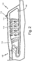
- FIG. 2 is a sectional view from FIG. 1 showing a combustor.
- FIG. 2 shows gas turbine engine 100 including rearward engine casing 104, at least one combustor 108, combustor liner 110, fuel rail 112, dilution chutes 114, and compressed air channel 116.
- Rearward engine casing 104 includes combustor 108 with combustor liner 110, fuel rail 112, and dilution chutes 114.
- Fuel rail 110 circumferentially surrounds rearward engine casing 104 and receives fuel from a fuel source such as a fuel tank.
- Fuel rail 112 delivers fuel to each combustor 108 through dilution chute 114, which is formed integral and conformal with combustor liner 110 and provides a wetting surface for the fuel entering dilution chute 114.
- integral means “formed as a unitary part” and conformal means “substantially following the geometry of.”
- Compressed air channel 116 surrounds combustor 108. Compressed air is received from the compressor section 103 (shown in FIG. 1 ) and enters combustor 108 through a series of dilution holes and dilution chutes 114.
- combustor 108 includes more than one dilution chute as shown in FIGS. 1 and 2 .
- the combustor may include more than one type of dilution chute.
- the combustor may include primary dilution chutes for allowing atomized fuel and air to enter the combustor and the combustor may also include secondary dilution chutes for allowing additional air to enter the combustor. In the illustrated embodiments in FIGS.
- each combustor 108 in gas turbine engine 100 includes twelve primary and twelve secondary dilution chutes with each set being circumferentially arranged around combustor liner 110.
- the placement, number, and orientation of the dilution chutes can be optimized for fuel efficiency. Factors which may influence fuel efficiency parameters are, for example, engine size, engine load and/or demand requirements, materials used in the build process, and engine cooling requirements. In other embodiments, a fewer or greater number of primary or secondary dilution chutes are integral and conformal with combustor liner 110.
- FIG. 3 is a cross-sectional view of a dilution chute within a combustor.
- gas turbine engine 100 including combustor 108, combustor liner 110, fuel rail 112, dilution chute 114, fuel line 116, tapered edge 118, vertex 120, and walls 122.
- Combustor 108 includes dilution chute 114 formed integral and conformal with combustor liner 110.
- Fuel rail 112 circumferentially surrounds rearward engine casing 104 (shown in FIGS. 1 and 2 ) and receives fuel from a fuel source such as a fuel tank.
- Fuel line 116 receives fuel from fuel rail 112 and delivers fuel to dilution chute 114, which provides a wetting surface for fuel exiting fuel line 116.
- Dilution chute 114 includes tapered edge 118 and vertex 120 extending from walls 122.
- Tapered edge 118 can have a substantially 45° angle of inclination measured from vertex 120.
- Tapered edge 118 can have an angle of inclination of more than 45°.
- Walls 122 extend radially away from combustor liner 110 into interior of combustor 108 terminating at tapered edge 118 and vortex 120.
- all walls 122 of dilution chute 114 have tapered edges 118.
- a subset of walls 122 of dilution chute 114 has tapered edge 118.
- tapered edge 118 can be referred to as having a knife edge shape.
- Gas turbine engine 100 including combustor 108, combustor liner 110, fuel rail 112, dilution chutes 114, fuel line 116, tapered edge 118, vertex 120, and walls 122 can be additively manufactured using any metal or alloy that can tolerate the high temperature and pressure environment of a gas turbine engine for the expected useable life of the vehicle, such as, for example, Inconel® 625 or other nickel alloys including alloys of nickel, chromium, and iron.
- guided munitions, missiles, and decoys are designed as single use vehicles and can have a maximum useable life of 10 hours. Heat protection that extends the useable life of the vehicle beyond 10 hours can unnecessarily add labor and expense to the manufacturing of such an engine.
- UAVs can be designed to perform multiple missions and more heat protection may be desirable.
- a specific metal or alloy with or without additional treatments to provide heat protection can be chosen with such considerations in mind.
- a thermal barrier layer or coating can be applied to the metal or alloy to extend the useful life of the gas turbine engine.
- FIG. 4A is a perspective view of one embodiment of a dilution chute.
- FIG. 4A shows gas turbine engine 100 including dilution chute 114, tapered edge 118, vortex 120, and walls 122.
- Dilution chute 114 includes tapered edge 118 and vertex 120 extending from walls 122. Walls 122 extend radially away from the combustor liner into the interior of the combustor.
- dilution chute 114 depicted in FIG. 4A , has four walls 122 with knife edge shaped tapered edges 118 and has a substantially square shape opening, dilution chute 114 can have any number of walls 122 or opening shape.
- dilution chute 114 can have a circular, oval, triangular, rhomboid, rectangular, pentagonal, or hexagonal opening shape with a corresponding number of walls 122.
- a circular or oval shaped opening has one wall; a triangular shaped opening has 3 walls; a rhomboid or rectangular shaped opening has 4 walls; a pentagonal shaped opening has 5 walls; and a hexagonal shaped opening has 6 walls.
- FIG. 4B is a perspective view of another embodiment of a dilution chute.
- FIG. 4B shows gas turbine engine 200 including dilution chute 214, tapered edge 218, vortices 220, and walls 222.
- Dilution chute 214 includes tapered edge 218 and vertex 220 extending from walls 222. Walls 222 extend radially away from the combustor liner into the interior of the combustor and terminate at tapered edge 218 and vortices 220.
- tapered edge 218 has a castellation shape. In other words, each tapered edge along each wall has a series of undulating plateaus and valleys with each plateau having a knife edge shape. As depicted in FIG. 4B , the intersection of any two walls 222 has vortex 220 with a peak shape.
- tapered edge has a saw tooth shape.
- each tapered edge along each wall has a series of undulating peaks and valleys with each peak defining a vortex.
- the tapered edge can have peaks, plateaus, and valleys in alternating, segregated, or partially segregated orientations relative to one another. Considerations such as, for example, reducing carbon build up on the dilution chute, combustion efficiency, cooling effects, additive manufacturing process controls, and robustness of the build can be used to determine the size, number, and orientation of the tapered edge features (i.e., knife edge shapes, castellation shapes, and saw tooth shapes defined by the peaks, plateaus, and valleys).
- a combustor with a dilution chute without tapered edges builds up carbon deposits on the dilution chute more readily compared to a dilution chute with tapered edges in a combustor.
- carbon deposits can alter the air flow characteristics in the combustor, reducing the combustion efficiency even more.
- carbon deposits can result in flaking, peeling, or breaking-off of the carbon deposits during engine operation. Large carbon deposits may damage internal downstream components as the carbon deposits travel through the engine.
- a gas turbine engine can be built with an integral and conformable dilution chute with tapered edges as disclosed in the present application, which simplifies the manufacturing and assembly process, lowering overall production costs.
- the dilution chute with tapered edges disclosed in the present application reduces the amount of carbon deposition on the dilution chute during engine operation compared to an experimental gas turbine engine without a dilution chute without tapered edges.
- a combustor for a gas turbine engine includes a combustor liner and a dilution chute integral and conformal with the combustor liner to provide an outlet into the combustor for fuel, wherein the dilution chute has at least one wall with a tapered edge extending into an interior of the combustor.
- the combustor of the preceding paragraph can optionally include, additionally and/or alternatively, any one or more of the following features, configurations and/or additional components:
- the dilution chute has four walls and a substantially square shaped opening.
- the tapered edge has a knife edge shape.
- the tapered edge has a castellation shaped edge.
- the tapered edge has a saw tooth shaped edge.
- the tapered edge has an angle of inclination of substantially 45 degrees.
- the tapered edge reduces carbon deposit formation on an exterior surface of the dilution chute compared to a dilution chute without a tapered edge.
- a method of manufacturing a combustor with an integral and conformal dilution chute having a tapered edge including additively manufacturing a combustor liner and additively manufacturing an integral and conformal dilution chute having a tapered edge with the combustor liner to provide an outlet into the combustor for fuel.
- the method of the preceding paragraph can optionally include, additionally and/or alternatively, any one or more of the following features, configurations and/or additional components:
- the tapered edge has a knife edge shape.
- the tapered edge has a castellation shaped edge.
- the tapered edge has a saw tooth shaped edge.
- the tapered edge has an angle of inclination of substantially 45 degrees.
- the tapered edge reduces carbon deposit formation on an exterior surface of the dilution chute compared to a dilution chute without a tapered edge.
- a gas turbine engine includes a compressor section and a combustor section in fluid communication with the compressor section.
- the combustion section includes a combustor liner and a dilution chute integral and conformal with the combustor liner to provide an outlet into the combustor for fuel and the dilution chute has a tapered edge extending into the combustor and the tapered edge reduces carbon buildup on an exterior surface of the dilution chute compared to a dilution chute without a tapered edge.
- the gas turbine engine includes a turbine section in fluid communication with the combustor section and an exhaust section in fluid communication with the turbine section.
Landscapes
- Engineering & Computer Science (AREA)
- Chemical & Material Sciences (AREA)
- Combustion & Propulsion (AREA)
- Mechanical Engineering (AREA)
- General Engineering & Computer Science (AREA)
- Turbine Rotor Nozzle Sealing (AREA)
- Powder Metallurgy (AREA)
Abstract
Description
- The present disclosure relates generally to gas turbine engines. More specifically, this disclosure relates to dilution chute geometry of a gas turbine engine.
- Some aircraft can include, for example, Unpiloted (or Unmanned) Aerial Vehicles (UAVs) and expendable turbojet systems for guided munitions, missiles, and decoys. These attritable aircraft are generally designed as limited lifetime vehicles, with expected lifetimes as short as a single use or single mission vehicle. As such, many components and features common in traditional piloted aircraft are unnecessary or can be simplified for attritable aircraft applications, including combustor systems.
- Conventional combustor systems including dilution chutes in aircraft, both of the attritable and non-attritable type, can have many individual parts, each requiring assembly, which can be expensive and time consuming. Furthermore, cross drilling through the engine support structures has conventionally been used in order to create necessary fluid passageways, which adds additional labor and expense to the manufacturing process.
- Proper combustion efficiency is essential for a gas turbine engine. Improper combustion efficiency can lead to the engine running too rich or too lean. On the one hand, a gas turbine engine running too rich can result in an engine producing low power due to incomplete combustion of the fuel, producing an engine surge or stall condition, and/or producing excessive carbon build up in the combustor. On the other hand, a gas turbine running too lean can lead to engine blow out due to insufficient fuel to sustain combustion.
- A combustor for a gas turbine engine includes a combustor liner and a dilution chute integral and conformal with the combustor liner to provide an outlet into the combustor for fuel, wherein the dilution chute has at least one wall with a tapered edge extending into an interior of the combustor.
- A method of manufacturing a combustor with an integral and conformal dilution chute having a tapered edge including additively manufacturing a combustor liner and additively manufacturing an integral and conformal dilution chute having a tapered edge with the combustor liner to provide an outlet into the combustor for fuel.
-
-
FIG. 1 is a cross-sectional view of a gas turbine engine. -
FIG. 2 is a sectional view fromFIG. 1 showing a combustor. -
FIG. 3 is a cross-sectional view of a dilution chute within a combustor. -
FIG. 4A is a perspective view of one embodiment of a dilution chute. -
FIG. 4B is a perspective view of another embodiment of a dilution chute. - A gas turbine engine with an integrally built dilution chute simplifies manufacturing. A gas turbine engine can leverage additive manufacturing techniques to improve various aspects of the gas turbine engine. For example, additive manufacturing allows assembly details to be unitized, and simultaneously permits integration of many complex performance-enhancing features. The additive manufacture of the engine reduces the time to delivery to the customer and lowers the overall production costs of the unit.
- Disclosed herein is a combustor with an integrally and conformally built dilution chute with tapered edges to reduce carbon build up on the dilution chute in the combustor of a gas turbine engine. In contrast, a combustor with a dilution chute without tapered edges builds up carbon deposits on the dilution chute compared to a dilution chute with tapered edges in a combustor. Carbon build up can interfere with the air flow in the combustor reducing the combustion efficiency even more. Furthermore, localized carbon build up can result in the carbon deposits breaking free and damaging engine components downstream of the combustor.
-
FIG. 1 is a cross-sectional view of a gas turbine engine.FIG. 1 showsgas turbine engine 100 includingforward engine casing 102,compressor section 103,rearward engine casing 104,turbine section 105,exhaust casing 106,combustor 108,combustor liner 110,fuel rail 112,dilution chutes 114,compressor blades 115,turbine blades 117,rotor 119, and rotational axis X.Forward engine casing 102 encases a compressor section ofgas turbine engine 100 and is connected torearward engine casing 104, which encases combustion and turbine sections ofgas turbine engine 100.Exhaust casing 106 is connected torearward engine casing 104, opposingforward engine casing 102. -
Rearward engine casing 104 includes at least onecombustor 108 withcombustor liner 110,fuel rail 112, anddilution chutes 114.Fuel rail 112 circumferentially surrounds rearwardengine casing 104 and receives fuel from a fuel source such as a fuel tank.Fuel rail 112 delivers fuel to eachcombustor 108 throughdilution chute 114, which is formed integral and conformal withcombustor liner 110. Although twocombustors 108 are depicted inFIG. 1 ,gas turbine engine 100 can include a single combustor or can include more than two combustors arranged circumferentially around rotational axis X. - Operationally, air enters the forward end of a
compressor section 103 encased byforward engine casing 102 and is compressed bycompressor blades 115. Compressed air along with fuel enterscombustor 108 throughdilution chutes 114 where the compressed air and fuel are combusted. The combusted fuel and compressed air fromcombustor 108 enter aturbine section 105 encased byrearward engine casing 104 and turnsturbine blades 117 circumferentially around rotational axis X, which generates power by also turningrotor 119 connected tocompressor blades 115. The air exits out of the aft end ofexhaust casing 106. -
FIG. 2 is a sectional view fromFIG. 1 showing a combustor.FIG. 2 showsgas turbine engine 100 includingrearward engine casing 104, at least onecombustor 108,combustor liner 110,fuel rail 112,dilution chutes 114, and compressedair channel 116.Rearward engine casing 104 includescombustor 108 withcombustor liner 110,fuel rail 112, anddilution chutes 114.Fuel rail 110 circumferentially surrounds rearwardengine casing 104 and receives fuel from a fuel source such as a fuel tank.Fuel rail 112 delivers fuel to eachcombustor 108 throughdilution chute 114, which is formed integral and conformal withcombustor liner 110 and provides a wetting surface for the fuel enteringdilution chute 114. In the context of this application, integral means "formed as a unitary part" and conformal means "substantially following the geometry of." -
Compressed air channel 116 surroundscombustor 108. Compressed air is received from the compressor section 103 (shown inFIG. 1 ) and enterscombustor 108 through a series of dilution holes anddilution chutes 114. In one embodiment,combustor 108 includes more than one dilution chute as shown inFIGS. 1 and2 . The combustor may include more than one type of dilution chute. For example, the combustor may include primary dilution chutes for allowing atomized fuel and air to enter the combustor and the combustor may also include secondary dilution chutes for allowing additional air to enter the combustor. In the illustrated embodiments inFIGS. 1 and2 , eachcombustor 108 ingas turbine engine 100 includes twelve primary and twelve secondary dilution chutes with each set being circumferentially arranged aroundcombustor liner 110. The placement, number, and orientation of the dilution chutes can be optimized for fuel efficiency. Factors which may influence fuel efficiency parameters are, for example, engine size, engine load and/or demand requirements, materials used in the build process, and engine cooling requirements. In other embodiments, a fewer or greater number of primary or secondary dilution chutes are integral and conformal withcombustor liner 110. -
FIG. 3 is a cross-sectional view of a dilution chute within a combustor.FIG. 3 showsgas turbine engine 100 includingcombustor 108,combustor liner 110,fuel rail 112,dilution chute 114,fuel line 116,tapered edge 118,vertex 120, andwalls 122. Combustor 108 includesdilution chute 114 formed integral and conformal withcombustor liner 110.Fuel rail 112 circumferentially surrounds rearward engine casing 104 (shown inFIGS. 1 and2 ) and receives fuel from a fuel source such as a fuel tank.Fuel line 116 receives fuel fromfuel rail 112 and delivers fuel todilution chute 114, which provides a wetting surface for fuel exitingfuel line 116. -
Dilution chute 114 includestapered edge 118 andvertex 120 extending fromwalls 122.Tapered edge 118 can have a substantially 45° angle of inclination measured fromvertex 120.Tapered edge 118 can have an angle of inclination of more than 45°.Walls 122 extend radially away fromcombustor liner 110 into interior ofcombustor 108 terminating attapered edge 118 andvortex 120. In one embodiment, allwalls 122 ofdilution chute 114 have taperededges 118. In one embodiment, a subset ofwalls 122 ofdilution chute 114 has taperededge 118. In some embodiments, taperededge 118 can be referred to as having a knife edge shape. -
Gas turbine engine 100 includingcombustor 108,combustor liner 110,fuel rail 112,dilution chutes 114,fuel line 116, taperededge 118,vertex 120, andwalls 122 can be additively manufactured using any metal or alloy that can tolerate the high temperature and pressure environment of a gas turbine engine for the expected useable life of the vehicle, such as, for example, Inconel® 625 or other nickel alloys including alloys of nickel, chromium, and iron. However, guided munitions, missiles, and decoys are designed as single use vehicles and can have a maximum useable life of 10 hours. Heat protection that extends the useable life of the vehicle beyond 10 hours can unnecessarily add labor and expense to the manufacturing of such an engine. On the other hand, some UAVs can be designed to perform multiple missions and more heat protection may be desirable. A specific metal or alloy with or without additional treatments to provide heat protection can be chosen with such considerations in mind. For example, a thermal barrier layer or coating can be applied to the metal or alloy to extend the useful life of the gas turbine engine. -
FIG. 4A is a perspective view of one embodiment of a dilution chute.FIG. 4A showsgas turbine engine 100 includingdilution chute 114, taperededge 118,vortex 120, andwalls 122.Dilution chute 114 includes taperededge 118 andvertex 120 extending fromwalls 122.Walls 122 extend radially away from the combustor liner into the interior of the combustor. Althoughdilution chute 114, depicted inFIG. 4A , has fourwalls 122 with knife edge shaped taperededges 118 and has a substantially square shape opening,dilution chute 114 can have any number ofwalls 122 or opening shape. For example,dilution chute 114 can have a circular, oval, triangular, rhomboid, rectangular, pentagonal, or hexagonal opening shape with a corresponding number ofwalls 122. For example, a circular or oval shaped opening has one wall; a triangular shaped opening has 3 walls; a rhomboid or rectangular shaped opening has 4 walls; a pentagonal shaped opening has 5 walls; and a hexagonal shaped opening has 6 walls. -
FIG. 4B is a perspective view of another embodiment of a dilution chute.FIG. 4B showsgas turbine engine 200 includingdilution chute 214, taperededge 218,vortices 220, andwalls 222.Dilution chute 214 includes taperededge 218 andvertex 220 extending fromwalls 222.Walls 222 extend radially away from the combustor liner into the interior of the combustor and terminate attapered edge 218 andvortices 220. As depicted inFIG. 4B , taperededge 218 has a castellation shape. In other words, each tapered edge along each wall has a series of undulating plateaus and valleys with each plateau having a knife edge shape. As depicted inFIG. 4B , the intersection of any twowalls 222 hasvortex 220 with a peak shape. - In one embodiment, tapered edge has a saw tooth shape. In other words, each tapered edge along each wall has a series of undulating peaks and valleys with each peak defining a vortex. In other embodiments, the tapered edge can have peaks, plateaus, and valleys in alternating, segregated, or partially segregated orientations relative to one another. Considerations such as, for example, reducing carbon build up on the dilution chute, combustion efficiency, cooling effects, additive manufacturing process controls, and robustness of the build can be used to determine the size, number, and orientation of the tapered edge features (i.e., knife edge shapes, castellation shapes, and saw tooth shapes defined by the peaks, plateaus, and valleys).
- A combustor with a dilution chute without tapered edges builds up carbon deposits on the dilution chute more readily compared to a dilution chute with tapered edges in a combustor. Notably, carbon deposits can alter the air flow characteristics in the combustor, reducing the combustion efficiency even more. Furthermore, carbon deposits can result in flaking, peeling, or breaking-off of the carbon deposits during engine operation. Large carbon deposits may damage internal downstream components as the carbon deposits travel through the engine.
- Using additive manufacturing techniques such as, for example, laser powder bed fusion, electron beam melting, and glue binder jetting, a gas turbine engine can be built with an integral and conformable dilution chute with tapered edges as disclosed in the present application, which simplifies the manufacturing and assembly process, lowering overall production costs. The dilution chute with tapered edges disclosed in the present application reduces the amount of carbon deposition on the dilution chute during engine operation compared to an experimental gas turbine engine without a dilution chute without tapered edges.
- The following are non-exclusive descriptions of possible embodiments of the present invention.
- A combustor for a gas turbine engine includes a combustor liner and a dilution chute integral and conformal with the combustor liner to provide an outlet into the combustor for fuel, wherein the dilution chute has at least one wall with a tapered edge extending into an interior of the combustor.
- The combustor of the preceding paragraph can optionally include, additionally and/or alternatively, any one or more of the following features, configurations and/or additional components:
The dilution chute has four walls and a substantially square shaped opening. - The tapered edge has a knife edge shape.
- The tapered edge has a castellation shaped edge.
- The tapered edge has a saw tooth shaped edge.
- The tapered edge has an angle of inclination of substantially 45 degrees.
- The tapered edge reduces carbon deposit formation on an exterior surface of the dilution chute compared to a dilution chute without a tapered edge.
- A method of manufacturing a combustor with an integral and conformal dilution chute having a tapered edge including additively manufacturing a combustor liner and additively manufacturing an integral and conformal dilution chute having a tapered edge with the combustor liner to provide an outlet into the combustor for fuel.
- The method of the preceding paragraph can optionally include, additionally and/or alternatively, any one or more of the following features, configurations and/or additional components:
The tapered edge has a knife edge shape. - The tapered edge has a castellation shaped edge.
- The tapered edge has a saw tooth shaped edge.
- The tapered edge has an angle of inclination of substantially 45 degrees.
- The tapered edge reduces carbon deposit formation on an exterior surface of the dilution chute compared to a dilution chute without a tapered edge.
- A gas turbine engine includes a compressor section and a combustor section in fluid communication with the compressor section. The combustion section includes a combustor liner and a dilution chute integral and conformal with the combustor liner to provide an outlet into the combustor for fuel and the dilution chute has a tapered edge extending into the combustor and the tapered edge reduces carbon buildup on an exterior surface of the dilution chute compared to a dilution chute without a tapered edge. The gas turbine engine includes a turbine section in fluid communication with the combustor section and an exhaust section in fluid communication with the turbine section.
- While the invention has been described with reference to an exemplary embodiment(s), it will be understood by those skilled in the art that various changes may be made and equivalents may be substituted for elements thereof without departing from the scope of the invention. In addition, many modifications may be made to adapt a particular situation or material to the teachings of the invention without departing from the essential scope thereof. Therefore, it is intended that the invention not be limited to the particular embodiment(s) disclosed, but that the invention will include all embodiments falling within the scope of the appended claims.
Claims (15)
- A combustor (108) for a gas turbine engine (100; 200), the combustor (108) comprising:a combustor liner (110); anda dilution chute (114; 214) integral and conformal with the combustor liner (110) to provide an outlet into the combustor (108) for fuel, wherein the dilution chute (114; 214) has at least one wall (122; 222) with a tapered edge (118; 218) extending into an interior of the combustor (108).
- The combustor of claim 1, wherein the dilution chute (114; 214) has four walls and a substantially square shaped opening.
- The combustor of claim 1 or 2, wherein the tapered edge (118) has a knife edge shape.
- The combustor of claim 1 or 2, wherein the tapered edge (218) has a castellation shaped edge.
- The combustor of claim 1 or 2, wherein the tapered edge has a saw tooth shaped edge.
- The combustor of any preceding claim, wherein the tapered edge (118; 218) has an angle of inclination of substantially 45 degrees.
- The combustor of any preceding claim, wherein the tapered edge (118; 218) reduces carbon deposit formation on an exterior surface of the dilution chute (114; 214) compared to a dilution chute without a tapered edge.
- A gas turbine engine (100; 200) comprising:a compressor section (103);a combustor section in fluid communication with the compressor section (103), the combustor section comprising the combustor (108) of any preceding claim;a turbine section (105) in fluid communication with the combustor section; andan exhaust section in fluid communication with the turbine section (105).
- A method of manufacturing a combustor (108) with an integral and conformal dilution chute (114; 214) having a tapered edge (118; 218), the method comprising:additively manufacturing a combustor liner (110); andadditively manufacturing an integral and conformal dilution chute (114; 214) having a tapered edge (118; 218) with the combustor liner (110) to provide an outlet into the combustor (108) for fuel.
- The method of claim 9, wherein the dilution chute (114; 214) has four walls and a substantially square shaped opening.
- The method of claim 9 or 10, wherein the tapered edge (118) has a knife edge shape.
- The method of claim 9 or 10, wherein the tapered edge (218) has a castellation shaped edge.
- The method of claim 9 or 10, wherein the tapered edge has a saw tooth shaped edge.
- The method of any of claims 9 to 13, wherein the tapered edge (118; 218) has an angle of inclination of substantially 45 degrees.
- The method of any of claims 9 to 14, wherein the tapered edge (118; 218) reduces carbon deposit formation on an exterior surface of the dilution chute (114; 214) compared to a dilution chute without a tapered edge.
Applications Claiming Priority (1)
| Application Number | Priority Date | Filing Date | Title |
|---|---|---|---|
| US16/791,499 US11543127B2 (en) | 2020-02-14 | 2020-02-14 | Gas turbine engine dilution chute geometry |
Publications (2)
| Publication Number | Publication Date |
|---|---|
| EP3865775A1 true EP3865775A1 (en) | 2021-08-18 |
| EP3865775B1 EP3865775B1 (en) | 2023-05-31 |
Family
ID=74595177
Family Applications (1)
| Application Number | Title | Priority Date | Filing Date |
|---|---|---|---|
| EP21156869.6A Active EP3865775B1 (en) | 2020-02-14 | 2021-02-12 | Gas turbine combustor with a dilution chute and associated method of manufacturing |
Country Status (2)
| Country | Link |
|---|---|
| US (1) | US11543127B2 (en) |
| EP (1) | EP3865775B1 (en) |
Cited By (2)
| Publication number | Priority date | Publication date | Assignee | Title |
|---|---|---|---|---|
| EP4545855A3 (en) * | 2023-10-27 | 2025-05-14 | RTX Corporation | Additively manufactured clocked fuel injector bolt for gas turbine engine combustor |
| EP4700292A1 (en) * | 2024-08-23 | 2026-02-25 | RTX Corporation | Additive manufactured primary combustor zone chute turbulators for enhance fuel delivery |
Families Citing this family (1)
| Publication number | Priority date | Publication date | Assignee | Title |
|---|---|---|---|---|
| US12516816B1 (en) * | 2025-03-14 | 2026-01-06 | Rtx Corporation | 3D diffuser fed scoop fuel injector |
Citations (7)
| Publication number | Priority date | Publication date | Assignee | Title |
|---|---|---|---|---|
| EP2639508A2 (en) * | 2012-03-15 | 2013-09-18 | General Electric Company | System for supplying a working fluid to a combustor |
| US20150285504A1 (en) * | 2014-04-08 | 2015-10-08 | General Electric Company | Trapped vortex fuel injector and method for manufacture |
| WO2016057009A1 (en) * | 2014-10-06 | 2016-04-14 | Siemens Aktiengesellschaft | Combustor and method for damping vibrational modes under high-frequency combustion dynamics |
| EP3249301A1 (en) * | 2016-05-26 | 2017-11-29 | Siemens Energy, Inc. | Ducting arrangement with injector assemblies arranged in an expanding cross-sectional area of a downstream combustion stage in a gas turbine engine |
| US20170370585A1 (en) * | 2016-06-22 | 2017-12-28 | General Electric Company | Combustor assembly for a turbine engine |
| WO2018063151A1 (en) * | 2016-09-27 | 2018-04-05 | Siemens Aktiengesellschaft | Fuel oil axial stage combustion for improved turbine combustor performance |
| US20190178497A1 (en) * | 2017-12-11 | 2019-06-13 | General Electric Company | Fuel injection assemblies for axial fuel staging in gas turbine combustors |
Family Cites Families (9)
| Publication number | Priority date | Publication date | Assignee | Title |
|---|---|---|---|---|
| US5749219A (en) * | 1989-11-30 | 1998-05-12 | United Technologies Corporation | Combustor with first and second zones |
| GB0219458D0 (en) * | 2002-08-21 | 2002-09-25 | Rolls Royce Plc | Fuel injection apparatus |
| US6931862B2 (en) | 2003-04-30 | 2005-08-23 | Hamilton Sundstrand Corporation | Combustor system for an expendable gas turbine engine |
| GB2470742B (en) * | 2009-06-03 | 2011-04-20 | Rolls Royce Plc | Fuel injector for a gas turbine engine |
| US9803498B2 (en) | 2012-10-17 | 2017-10-31 | United Technologies Corporation | One-piece fuel nozzle for a thrust engine |
| US9327965B2 (en) | 2013-03-15 | 2016-05-03 | Versana Micro Inc | Transportation device having a monolithically integrated multi-sensor device on a semiconductor substrate and method therefor |
| US9551490B2 (en) * | 2014-04-08 | 2017-01-24 | General Electric Company | System for cooling a fuel injector extending into a combustion gas flow field and method for manufacture |
| US20170059159A1 (en) * | 2015-08-25 | 2017-03-02 | Rolls-Royce Corporation | Cmc combustor shell with integral chutes |
| US10816203B2 (en) * | 2017-12-11 | 2020-10-27 | General Electric Company | Thimble assemblies for introducing a cross-flow into a secondary combustion zone |
-
2020
- 2020-02-14 US US16/791,499 patent/US11543127B2/en active Active
-
2021
- 2021-02-12 EP EP21156869.6A patent/EP3865775B1/en active Active
Patent Citations (7)
| Publication number | Priority date | Publication date | Assignee | Title |
|---|---|---|---|---|
| EP2639508A2 (en) * | 2012-03-15 | 2013-09-18 | General Electric Company | System for supplying a working fluid to a combustor |
| US20150285504A1 (en) * | 2014-04-08 | 2015-10-08 | General Electric Company | Trapped vortex fuel injector and method for manufacture |
| WO2016057009A1 (en) * | 2014-10-06 | 2016-04-14 | Siemens Aktiengesellschaft | Combustor and method for damping vibrational modes under high-frequency combustion dynamics |
| EP3249301A1 (en) * | 2016-05-26 | 2017-11-29 | Siemens Energy, Inc. | Ducting arrangement with injector assemblies arranged in an expanding cross-sectional area of a downstream combustion stage in a gas turbine engine |
| US20170370585A1 (en) * | 2016-06-22 | 2017-12-28 | General Electric Company | Combustor assembly for a turbine engine |
| WO2018063151A1 (en) * | 2016-09-27 | 2018-04-05 | Siemens Aktiengesellschaft | Fuel oil axial stage combustion for improved turbine combustor performance |
| US20190178497A1 (en) * | 2017-12-11 | 2019-06-13 | General Electric Company | Fuel injection assemblies for axial fuel staging in gas turbine combustors |
Cited By (2)
| Publication number | Priority date | Publication date | Assignee | Title |
|---|---|---|---|---|
| EP4545855A3 (en) * | 2023-10-27 | 2025-05-14 | RTX Corporation | Additively manufactured clocked fuel injector bolt for gas turbine engine combustor |
| EP4700292A1 (en) * | 2024-08-23 | 2026-02-25 | RTX Corporation | Additive manufactured primary combustor zone chute turbulators for enhance fuel delivery |
Also Published As
| Publication number | Publication date |
|---|---|
| EP3865775B1 (en) | 2023-05-31 |
| US20210254831A1 (en) | 2021-08-19 |
| US11543127B2 (en) | 2023-01-03 |
Similar Documents
| Publication | Publication Date | Title |
|---|---|---|
| EP3865774B1 (en) | Gas turbine combustor with integrated fuel swirlers | |
| EP3865775B1 (en) | Gas turbine combustor with a dilution chute and associated method of manufacturing | |
| EP3015648B1 (en) | Cooled component | |
| EP3006831B1 (en) | A cooled component | |
| US7805944B2 (en) | Combustion chamber air inlet | |
| US10927762B2 (en) | Cooled component | |
| EP1873459B1 (en) | Flameholder fuel-shield | |
| EP3176372B1 (en) | A cooled component of a turbomachine | |
| EP2083220A2 (en) | Effusion cooling for gas turbine combustors | |
| EP1104872A1 (en) | Method for decreasing a heat load on a combustor liner | |
| EP3822541B1 (en) | Integrated front panel for a burner of a gas turbine engine | |
| US11753952B2 (en) | Support structure for a turbine vane of a gas turbine engine | |
| US11466593B2 (en) | Double walled stator housing | |
| EP2896786B1 (en) | Turbine rotor assemblies with improved slot cavities | |
| US6782620B2 (en) | Methods for replacing a portion of a combustor dome assembly | |
| EP3855074B1 (en) | Combustion chamber for a gas turbine engine with a particle separator | |
| US12044409B2 (en) | Casing integrated fluid distribution system | |
| US12595907B2 (en) | Inspection port for an attritable engine support structure | |
| CN119508843A (en) | Heat shields for gas turbine engines |
Legal Events
| Date | Code | Title | Description |
|---|---|---|---|
| PUAI | Public reference made under article 153(3) epc to a published international application that has entered the european phase |
Free format text: ORIGINAL CODE: 0009012 |
|
| STAA | Information on the status of an ep patent application or granted ep patent |
Free format text: STATUS: THE APPLICATION HAS BEEN PUBLISHED |
|
| AK | Designated contracting states |
Kind code of ref document: A1 Designated state(s): AL AT BE BG CH CY CZ DE DK EE ES FI FR GB GR HR HU IE IS IT LI LT LU LV MC MK MT NL NO PL PT RO RS SE SI SK SM TR |
|
| STAA | Information on the status of an ep patent application or granted ep patent |
Free format text: STATUS: REQUEST FOR EXAMINATION WAS MADE |
|
| 17P | Request for examination filed |
Effective date: 20220215 |
|
| RBV | Designated contracting states (corrected) |
Designated state(s): AL AT BE BG CH CY CZ DE DK EE ES FI FR GB GR HR HU IE IS IT LI LT LU LV MC MK MT NL NO PL PT RO RS SE SI SK SM TR |
|
| GRAP | Despatch of communication of intention to grant a patent |
Free format text: ORIGINAL CODE: EPIDOSNIGR1 |
|
| STAA | Information on the status of an ep patent application or granted ep patent |
Free format text: STATUS: GRANT OF PATENT IS INTENDED |
|
| INTG | Intention to grant announced |
Effective date: 20221209 |
|
| GRAS | Grant fee paid |
Free format text: ORIGINAL CODE: EPIDOSNIGR3 |
|
| GRAA | (expected) grant |
Free format text: ORIGINAL CODE: 0009210 |
|
| STAA | Information on the status of an ep patent application or granted ep patent |
Free format text: STATUS: THE PATENT HAS BEEN GRANTED |
|
| AK | Designated contracting states |
Kind code of ref document: B1 Designated state(s): AL AT BE BG CH CY CZ DE DK EE ES FI FR GB GR HR HU IE IS IT LI LT LU LV MC MK MT NL NO PL PT RO RS SE SI SK SM TR |
|
| REG | Reference to a national code |
Ref country code: GB Ref legal event code: FG4D Ref country code: CH Ref legal event code: EP |
|
| REG | Reference to a national code |
Ref country code: DE Ref legal event code: R096 Ref document number: 602021002499 Country of ref document: DE |
|
| REG | Reference to a national code |
Ref country code: AT Ref legal event code: REF Ref document number: 1571120 Country of ref document: AT Kind code of ref document: T Effective date: 20230615 |
|
| REG | Reference to a national code |
Ref country code: IE Ref legal event code: FG4D |
|
| REG | Reference to a national code |
Ref country code: LT Ref legal event code: MG9D |
|
| REG | Reference to a national code |
Ref country code: NL Ref legal event code: MP Effective date: 20230531 |
|
| REG | Reference to a national code |
Ref country code: AT Ref legal event code: MK05 Ref document number: 1571120 Country of ref document: AT Kind code of ref document: T Effective date: 20230531 |
|
| PG25 | Lapsed in a contracting state [announced via postgrant information from national office to epo] |
Ref country code: SE Free format text: LAPSE BECAUSE OF FAILURE TO SUBMIT A TRANSLATION OF THE DESCRIPTION OR TO PAY THE FEE WITHIN THE PRESCRIBED TIME-LIMIT Effective date: 20230531 Ref country code: NO Free format text: LAPSE BECAUSE OF FAILURE TO SUBMIT A TRANSLATION OF THE DESCRIPTION OR TO PAY THE FEE WITHIN THE PRESCRIBED TIME-LIMIT Effective date: 20230831 Ref country code: ES Free format text: LAPSE BECAUSE OF FAILURE TO SUBMIT A TRANSLATION OF THE DESCRIPTION OR TO PAY THE FEE WITHIN THE PRESCRIBED TIME-LIMIT Effective date: 20230531 Ref country code: AT Free format text: LAPSE BECAUSE OF FAILURE TO SUBMIT A TRANSLATION OF THE DESCRIPTION OR TO PAY THE FEE WITHIN THE PRESCRIBED TIME-LIMIT Effective date: 20230531 |
|
| RAP4 | Party data changed (patent owner data changed or rights of a patent transferred) |
Owner name: RTX CORPORATION |
|
| PG25 | Lapsed in a contracting state [announced via postgrant information from national office to epo] |
Ref country code: RS Free format text: LAPSE BECAUSE OF FAILURE TO SUBMIT A TRANSLATION OF THE DESCRIPTION OR TO PAY THE FEE WITHIN THE PRESCRIBED TIME-LIMIT Effective date: 20230531 Ref country code: PL Free format text: LAPSE BECAUSE OF FAILURE TO SUBMIT A TRANSLATION OF THE DESCRIPTION OR TO PAY THE FEE WITHIN THE PRESCRIBED TIME-LIMIT Effective date: 20230531 Ref country code: NL Free format text: LAPSE BECAUSE OF FAILURE TO SUBMIT A TRANSLATION OF THE DESCRIPTION OR TO PAY THE FEE WITHIN THE PRESCRIBED TIME-LIMIT Effective date: 20230531 Ref country code: LV Free format text: LAPSE BECAUSE OF FAILURE TO SUBMIT A TRANSLATION OF THE DESCRIPTION OR TO PAY THE FEE WITHIN THE PRESCRIBED TIME-LIMIT Effective date: 20230531 Ref country code: LT Free format text: LAPSE BECAUSE OF FAILURE TO SUBMIT A TRANSLATION OF THE DESCRIPTION OR TO PAY THE FEE WITHIN THE PRESCRIBED TIME-LIMIT Effective date: 20230531 Ref country code: IS Free format text: LAPSE BECAUSE OF FAILURE TO SUBMIT A TRANSLATION OF THE DESCRIPTION OR TO PAY THE FEE WITHIN THE PRESCRIBED TIME-LIMIT Effective date: 20230930 Ref country code: HR Free format text: LAPSE BECAUSE OF FAILURE TO SUBMIT A TRANSLATION OF THE DESCRIPTION OR TO PAY THE FEE WITHIN THE PRESCRIBED TIME-LIMIT Effective date: 20230531 Ref country code: GR Free format text: LAPSE BECAUSE OF FAILURE TO SUBMIT A TRANSLATION OF THE DESCRIPTION OR TO PAY THE FEE WITHIN THE PRESCRIBED TIME-LIMIT Effective date: 20230901 |
|
| PG25 | Lapsed in a contracting state [announced via postgrant information from national office to epo] |
Ref country code: FI Free format text: LAPSE BECAUSE OF FAILURE TO SUBMIT A TRANSLATION OF THE DESCRIPTION OR TO PAY THE FEE WITHIN THE PRESCRIBED TIME-LIMIT Effective date: 20230531 |
|
| PG25 | Lapsed in a contracting state [announced via postgrant information from national office to epo] |
Ref country code: SK Free format text: LAPSE BECAUSE OF FAILURE TO SUBMIT A TRANSLATION OF THE DESCRIPTION OR TO PAY THE FEE WITHIN THE PRESCRIBED TIME-LIMIT Effective date: 20230531 |
|
| PG25 | Lapsed in a contracting state [announced via postgrant information from national office to epo] |
Ref country code: SM Free format text: LAPSE BECAUSE OF FAILURE TO SUBMIT A TRANSLATION OF THE DESCRIPTION OR TO PAY THE FEE WITHIN THE PRESCRIBED TIME-LIMIT Effective date: 20230531 Ref country code: SK Free format text: LAPSE BECAUSE OF FAILURE TO SUBMIT A TRANSLATION OF THE DESCRIPTION OR TO PAY THE FEE WITHIN THE PRESCRIBED TIME-LIMIT Effective date: 20230531 Ref country code: RO Free format text: LAPSE BECAUSE OF FAILURE TO SUBMIT A TRANSLATION OF THE DESCRIPTION OR TO PAY THE FEE WITHIN THE PRESCRIBED TIME-LIMIT Effective date: 20230531 Ref country code: PT Free format text: LAPSE BECAUSE OF FAILURE TO SUBMIT A TRANSLATION OF THE DESCRIPTION OR TO PAY THE FEE WITHIN THE PRESCRIBED TIME-LIMIT Effective date: 20231002 Ref country code: EE Free format text: LAPSE BECAUSE OF FAILURE TO SUBMIT A TRANSLATION OF THE DESCRIPTION OR TO PAY THE FEE WITHIN THE PRESCRIBED TIME-LIMIT Effective date: 20230531 Ref country code: DK Free format text: LAPSE BECAUSE OF FAILURE TO SUBMIT A TRANSLATION OF THE DESCRIPTION OR TO PAY THE FEE WITHIN THE PRESCRIBED TIME-LIMIT Effective date: 20230531 Ref country code: CZ Free format text: LAPSE BECAUSE OF FAILURE TO SUBMIT A TRANSLATION OF THE DESCRIPTION OR TO PAY THE FEE WITHIN THE PRESCRIBED TIME-LIMIT Effective date: 20230531 |
|
| REG | Reference to a national code |
Ref country code: DE Ref legal event code: R097 Ref document number: 602021002499 Country of ref document: DE |
|
| PLBE | No opposition filed within time limit |
Free format text: ORIGINAL CODE: 0009261 |
|
| STAA | Information on the status of an ep patent application or granted ep patent |
Free format text: STATUS: NO OPPOSITION FILED WITHIN TIME LIMIT |
|
| PG25 | Lapsed in a contracting state [announced via postgrant information from national office to epo] |
Ref country code: SI Free format text: LAPSE BECAUSE OF FAILURE TO SUBMIT A TRANSLATION OF THE DESCRIPTION OR TO PAY THE FEE WITHIN THE PRESCRIBED TIME-LIMIT Effective date: 20230531 |
|
| 26N | No opposition filed |
Effective date: 20240301 |
|
| PG25 | Lapsed in a contracting state [announced via postgrant information from national office to epo] |
Ref country code: SI Free format text: LAPSE BECAUSE OF FAILURE TO SUBMIT A TRANSLATION OF THE DESCRIPTION OR TO PAY THE FEE WITHIN THE PRESCRIBED TIME-LIMIT Effective date: 20230531 Ref country code: IT Free format text: LAPSE BECAUSE OF FAILURE TO SUBMIT A TRANSLATION OF THE DESCRIPTION OR TO PAY THE FEE WITHIN THE PRESCRIBED TIME-LIMIT Effective date: 20230531 |
|
| PG25 | Lapsed in a contracting state [announced via postgrant information from national office to epo] |
Ref country code: MC Free format text: LAPSE BECAUSE OF FAILURE TO SUBMIT A TRANSLATION OF THE DESCRIPTION OR TO PAY THE FEE WITHIN THE PRESCRIBED TIME-LIMIT Effective date: 20230531 |
|
| REG | Reference to a national code |
Ref country code: CH Ref legal event code: PL |
|
| PG25 | Lapsed in a contracting state [announced via postgrant information from national office to epo] |
Ref country code: LU Free format text: LAPSE BECAUSE OF NON-PAYMENT OF DUE FEES Effective date: 20240212 |
|
| PG25 | Lapsed in a contracting state [announced via postgrant information from national office to epo] |
Ref country code: CH Free format text: LAPSE BECAUSE OF NON-PAYMENT OF DUE FEES Effective date: 20240229 |
|
| PG25 | Lapsed in a contracting state [announced via postgrant information from national office to epo] |
Ref country code: LU Free format text: LAPSE BECAUSE OF NON-PAYMENT OF DUE FEES Effective date: 20240212 Ref country code: CH Free format text: LAPSE BECAUSE OF NON-PAYMENT OF DUE FEES Effective date: 20240229 |
|
| PG25 | Lapsed in a contracting state [announced via postgrant information from national office to epo] |
Ref country code: BG Free format text: LAPSE BECAUSE OF FAILURE TO SUBMIT A TRANSLATION OF THE DESCRIPTION OR TO PAY THE FEE WITHIN THE PRESCRIBED TIME-LIMIT Effective date: 20230531 |
|
| PG25 | Lapsed in a contracting state [announced via postgrant information from national office to epo] |
Ref country code: BG Free format text: LAPSE BECAUSE OF FAILURE TO SUBMIT A TRANSLATION OF THE DESCRIPTION OR TO PAY THE FEE WITHIN THE PRESCRIBED TIME-LIMIT Effective date: 20230531 |
|
| REG | Reference to a national code |
Ref country code: BE Ref legal event code: MM Effective date: 20240229 |
|
| PG25 | Lapsed in a contracting state [announced via postgrant information from national office to epo] |
Ref country code: BE Free format text: LAPSE BECAUSE OF NON-PAYMENT OF DUE FEES Effective date: 20240229 |
|
| PG25 | Lapsed in a contracting state [announced via postgrant information from national office to epo] |
Ref country code: IE Free format text: LAPSE BECAUSE OF NON-PAYMENT OF DUE FEES Effective date: 20240212 |
|
| PG25 | Lapsed in a contracting state [announced via postgrant information from national office to epo] |
Ref country code: IE Free format text: LAPSE BECAUSE OF NON-PAYMENT OF DUE FEES Effective date: 20240212 Ref country code: BE Free format text: LAPSE BECAUSE OF NON-PAYMENT OF DUE FEES Effective date: 20240229 |
|
| PG25 | Lapsed in a contracting state [announced via postgrant information from national office to epo] |
Ref country code: CY Free format text: LAPSE BECAUSE OF FAILURE TO SUBMIT A TRANSLATION OF THE DESCRIPTION OR TO PAY THE FEE WITHIN THE PRESCRIBED TIME-LIMIT; INVALID AB INITIO Effective date: 20210212 |
|
| PG25 | Lapsed in a contracting state [announced via postgrant information from national office to epo] |
Ref country code: HU Free format text: LAPSE BECAUSE OF FAILURE TO SUBMIT A TRANSLATION OF THE DESCRIPTION OR TO PAY THE FEE WITHIN THE PRESCRIBED TIME-LIMIT; INVALID AB INITIO Effective date: 20210212 |
|
| REG | Reference to a national code |
Ref country code: DE Ref legal event code: R081 Ref document number: 602021002499 Country of ref document: DE Owner name: RTX CORPORATION (N.D.GES.D. STAATES DELAWARE),, US Free format text: FORMER OWNER: RAYTHEON TECHNOLOGIES CORPORATION, FARMINGTON, CT, US |
|
| PG25 | Lapsed in a contracting state [announced via postgrant information from national office to epo] |
Ref country code: TR Free format text: LAPSE BECAUSE OF FAILURE TO SUBMIT A TRANSLATION OF THE DESCRIPTION OR TO PAY THE FEE WITHIN THE PRESCRIBED TIME-LIMIT Effective date: 20230531 |
|
| P01 | Opt-out of the competence of the unified patent court (upc) registered |
Free format text: CASE NUMBER: UPC_APP_0019211_3865775/2025 Effective date: 20251223 |
|
| PGFP | Annual fee paid to national office [announced via postgrant information from national office to epo] |
Ref country code: GB Payment date: 20260122 Year of fee payment: 6 |
|
| PGFP | Annual fee paid to national office [announced via postgrant information from national office to epo] |
Ref country code: DE Payment date: 20260121 Year of fee payment: 6 |
|
| PGFP | Annual fee paid to national office [announced via postgrant information from national office to epo] |
Ref country code: FR Payment date: 20260121 Year of fee payment: 6 |