EP3015648B1 - Cooled component - Google Patents
Cooled component Download PDFInfo
- Publication number
- EP3015648B1 EP3015648B1 EP15187835.2A EP15187835A EP3015648B1 EP 3015648 B1 EP3015648 B1 EP 3015648B1 EP 15187835 A EP15187835 A EP 15187835A EP 3015648 B1 EP3015648 B1 EP 3015648B1
- Authority
- EP
- European Patent Office
- Prior art keywords
- recess
- effusion cooling
- cooled component
- wall
- upstream end
- Prior art date
- Legal status (The legal status is an assumption and is not a legal conclusion. Google has not performed a legal analysis and makes no representation as to the accuracy of the status listed.)
- Active
Links
- 238000001816 cooling Methods 0.000 claims description 197
- 238000011144 upstream manufacturing Methods 0.000 claims description 96
- 238000002485 combustion reaction Methods 0.000 claims description 72
- 239000012720 thermal barrier coating Substances 0.000 claims description 36
- 230000007704 transition Effects 0.000 claims description 8
- 238000004519 manufacturing process Methods 0.000 claims description 7
- 241000826860 Trapezium Species 0.000 claims description 5
- 239000000654 additive Substances 0.000 claims description 5
- 230000000996 additive effect Effects 0.000 claims description 5
- 238000009792 diffusion process Methods 0.000 claims description 3
- 239000007789 gas Substances 0.000 description 31
- 239000002826 coolant Substances 0.000 description 28
- MCMNRKCIXSYSNV-UHFFFAOYSA-N Zirconium dioxide Chemical compound O=[Zr]=O MCMNRKCIXSYSNV-UHFFFAOYSA-N 0.000 description 10
- 239000011248 coating agent Substances 0.000 description 8
- 238000000576 coating method Methods 0.000 description 8
- 239000000446 fuel Substances 0.000 description 8
- 238000003754 machining Methods 0.000 description 6
- 239000000843 powder Substances 0.000 description 6
- 229910000951 Aluminide Inorganic materials 0.000 description 5
- 238000000151 deposition Methods 0.000 description 5
- 230000008021 deposition Effects 0.000 description 5
- PXHVJJICTQNCMI-UHFFFAOYSA-N Nickel Chemical compound [Ni] PXHVJJICTQNCMI-UHFFFAOYSA-N 0.000 description 4
- 239000000463 material Substances 0.000 description 4
- 230000008901 benefit Effects 0.000 description 3
- 238000005524 ceramic coating Methods 0.000 description 3
- 239000011651 chromium Substances 0.000 description 3
- 238000005553 drilling Methods 0.000 description 3
- 239000000945 filler Substances 0.000 description 3
- 229910052751 metal Inorganic materials 0.000 description 3
- 239000002184 metal Substances 0.000 description 3
- 238000000034 method Methods 0.000 description 3
- 238000005245 sintering Methods 0.000 description 3
- 239000000126 substance Substances 0.000 description 3
- VYZAMTAEIAYCRO-UHFFFAOYSA-N Chromium Chemical compound [Cr] VYZAMTAEIAYCRO-UHFFFAOYSA-N 0.000 description 2
- XEEYBQQBJWHFJM-UHFFFAOYSA-N Iron Chemical compound [Fe] XEEYBQQBJWHFJM-UHFFFAOYSA-N 0.000 description 2
- 230000004888 barrier function Effects 0.000 description 2
- 230000000903 blocking effect Effects 0.000 description 2
- 238000005266 casting Methods 0.000 description 2
- 229910052804 chromium Inorganic materials 0.000 description 2
- 229910017052 cobalt Inorganic materials 0.000 description 2
- 239000010941 cobalt Substances 0.000 description 2
- GUTLYIVDDKVIGB-UHFFFAOYSA-N cobalt atom Chemical compound [Co] GUTLYIVDDKVIGB-UHFFFAOYSA-N 0.000 description 2
- 230000007797 corrosion Effects 0.000 description 2
- 238000005260 corrosion Methods 0.000 description 2
- 229910052759 nickel Inorganic materials 0.000 description 2
- 230000003647 oxidation Effects 0.000 description 2
- 238000007254 oxidation reaction Methods 0.000 description 2
- BASFCYQUMIYNBI-UHFFFAOYSA-N platinum Chemical compound [Pt] BASFCYQUMIYNBI-UHFFFAOYSA-N 0.000 description 2
- 230000001141 propulsive effect Effects 0.000 description 2
- 229910000601 superalloy Inorganic materials 0.000 description 2
- XLYOFNOQVPJJNP-UHFFFAOYSA-N water Substances O XLYOFNOQVPJJNP-UHFFFAOYSA-N 0.000 description 2
- RUDFQVOCFDJEEF-UHFFFAOYSA-N yttrium(III) oxide Inorganic materials [O-2].[O-2].[O-2].[Y+3].[Y+3] RUDFQVOCFDJEEF-UHFFFAOYSA-N 0.000 description 2
- 239000003082 abrasive agent Substances 0.000 description 1
- 230000002411 adverse Effects 0.000 description 1
- 239000004411 aluminium Substances 0.000 description 1
- 229910052782 aluminium Inorganic materials 0.000 description 1
- XAGFODPZIPBFFR-UHFFFAOYSA-N aluminium Chemical compound [Al] XAGFODPZIPBFFR-UHFFFAOYSA-N 0.000 description 1
- 238000005219 brazing Methods 0.000 description 1
- CETPSERCERDGAM-UHFFFAOYSA-N ceric oxide Chemical compound O=[Ce]=O CETPSERCERDGAM-UHFFFAOYSA-N 0.000 description 1
- 229910000422 cerium(IV) oxide Inorganic materials 0.000 description 1
- MMAADVOQRITKKL-UHFFFAOYSA-N chromium platinum Chemical compound [Cr].[Pt] MMAADVOQRITKKL-UHFFFAOYSA-N 0.000 description 1
- 238000000313 electron-beam-induced deposition Methods 0.000 description 1
- ZXGIFJXRQHZCGJ-UHFFFAOYSA-N erbium(3+);oxygen(2-) Chemical compound [O-2].[O-2].[O-2].[Er+3].[Er+3] ZXGIFJXRQHZCGJ-UHFFFAOYSA-N 0.000 description 1
- VQCBHWLJZDBHOS-UHFFFAOYSA-N erbium(III) oxide Inorganic materials O=[Er]O[Er]=O VQCBHWLJZDBHOS-UHFFFAOYSA-N 0.000 description 1
- 239000012530 fluid Substances 0.000 description 1
- 238000007689 inspection Methods 0.000 description 1
- 229910052742 iron Inorganic materials 0.000 description 1
- 229910052746 lanthanum Inorganic materials 0.000 description 1
- FZLIPJUXYLNCLC-UHFFFAOYSA-N lanthanum atom Chemical compound [La] FZLIPJUXYLNCLC-UHFFFAOYSA-N 0.000 description 1
- 239000000203 mixture Substances 0.000 description 1
- 238000012986 modification Methods 0.000 description 1
- 230000004048 modification Effects 0.000 description 1
- 229910052697 platinum Inorganic materials 0.000 description 1
- 230000008569 process Effects 0.000 description 1
- 229910052761 rare earth metal Inorganic materials 0.000 description 1
- 150000002910 rare earth metals Chemical class 0.000 description 1
- 238000000110 selective laser sintering Methods 0.000 description 1
- 230000035939 shock Effects 0.000 description 1
- 229910021332 silicide Inorganic materials 0.000 description 1
- FVBUAEGBCNSCDD-UHFFFAOYSA-N silicide(4-) Chemical compound [Si-4] FVBUAEGBCNSCDD-UHFFFAOYSA-N 0.000 description 1
- 238000003466 welding Methods 0.000 description 1
- 229910052727 yttrium Inorganic materials 0.000 description 1
- VWQVUPCCIRVNHF-UHFFFAOYSA-N yttrium atom Chemical compound [Y] VWQVUPCCIRVNHF-UHFFFAOYSA-N 0.000 description 1
Images


Classifications
-
- F—MECHANICAL ENGINEERING; LIGHTING; HEATING; WEAPONS; BLASTING
- F01—MACHINES OR ENGINES IN GENERAL; ENGINE PLANTS IN GENERAL; STEAM ENGINES
- F01D—NON-POSITIVE DISPLACEMENT MACHINES OR ENGINES, e.g. STEAM TURBINES
- F01D5/00—Blades; Blade-carrying members; Heating, heat-insulating, cooling or antivibration means on the blades or the members
- F01D5/12—Blades
- F01D5/14—Form or construction
- F01D5/18—Hollow blades, i.e. blades with cooling or heating channels or cavities; Heating, heat-insulating or cooling means on blades
- F01D5/186—Film cooling
-
- F—MECHANICAL ENGINEERING; LIGHTING; HEATING; WEAPONS; BLASTING
- F01—MACHINES OR ENGINES IN GENERAL; ENGINE PLANTS IN GENERAL; STEAM ENGINES
- F01D—NON-POSITIVE DISPLACEMENT MACHINES OR ENGINES, e.g. STEAM TURBINES
- F01D5/00—Blades; Blade-carrying members; Heating, heat-insulating, cooling or antivibration means on the blades or the members
- F01D5/12—Blades
- F01D5/14—Form or construction
- F01D5/18—Hollow blades, i.e. blades with cooling or heating channels or cavities; Heating, heat-insulating or cooling means on blades
- F01D5/187—Convection cooling
- F01D5/188—Convection cooling with an insert in the blade cavity to guide the cooling fluid, e.g. forming a separation wall
-
- F—MECHANICAL ENGINEERING; LIGHTING; HEATING; WEAPONS; BLASTING
- F01—MACHINES OR ENGINES IN GENERAL; ENGINE PLANTS IN GENERAL; STEAM ENGINES
- F01D—NON-POSITIVE DISPLACEMENT MACHINES OR ENGINES, e.g. STEAM TURBINES
- F01D9/00—Stators
- F01D9/06—Fluid supply conduits to nozzles or the like
- F01D9/065—Fluid supply or removal conduits traversing the working fluid flow, e.g. for lubrication-, cooling-, or sealing fluids
-
- F—MECHANICAL ENGINEERING; LIGHTING; HEATING; WEAPONS; BLASTING
- F23—COMBUSTION APPARATUS; COMBUSTION PROCESSES
- F23R—GENERATING COMBUSTION PRODUCTS OF HIGH PRESSURE OR HIGH VELOCITY, e.g. GAS-TURBINE COMBUSTION CHAMBERS
- F23R3/00—Continuous combustion chambers using liquid or gaseous fuel
- F23R3/002—Wall structures
-
- F—MECHANICAL ENGINEERING; LIGHTING; HEATING; WEAPONS; BLASTING
- F23—COMBUSTION APPARATUS; COMBUSTION PROCESSES
- F23R—GENERATING COMBUSTION PRODUCTS OF HIGH PRESSURE OR HIGH VELOCITY, e.g. GAS-TURBINE COMBUSTION CHAMBERS
- F23R3/00—Continuous combustion chambers using liquid or gaseous fuel
- F23R3/005—Combined with pressure or heat exchangers
-
- F—MECHANICAL ENGINEERING; LIGHTING; HEATING; WEAPONS; BLASTING
- F05—INDEXING SCHEMES RELATING TO ENGINES OR PUMPS IN VARIOUS SUBCLASSES OF CLASSES F01-F04
- F05B—INDEXING SCHEME RELATING TO WIND, SPRING, WEIGHT, INERTIA OR LIKE MOTORS, TO MACHINES OR ENGINES FOR LIQUIDS COVERED BY SUBCLASSES F03B, F03D AND F03G
- F05B2260/00—Function
- F05B2260/20—Heat transfer, e.g. cooling
- F05B2260/202—Heat transfer, e.g. cooling by film cooling
-
- F—MECHANICAL ENGINEERING; LIGHTING; HEATING; WEAPONS; BLASTING
- F05—INDEXING SCHEMES RELATING TO ENGINES OR PUMPS IN VARIOUS SUBCLASSES OF CLASSES F01-F04
- F05D—INDEXING SCHEME FOR ASPECTS RELATING TO NON-POSITIVE-DISPLACEMENT MACHINES OR ENGINES, GAS-TURBINES OR JET-PROPULSION PLANTS
- F05D2240/00—Components
- F05D2240/80—Platforms for stationary or moving blades
- F05D2240/81—Cooled platforms
-
- F—MECHANICAL ENGINEERING; LIGHTING; HEATING; WEAPONS; BLASTING
- F05—INDEXING SCHEMES RELATING TO ENGINES OR PUMPS IN VARIOUS SUBCLASSES OF CLASSES F01-F04
- F05D—INDEXING SCHEME FOR ASPECTS RELATING TO NON-POSITIVE-DISPLACEMENT MACHINES OR ENGINES, GAS-TURBINES OR JET-PROPULSION PLANTS
- F05D2260/00—Function
- F05D2260/20—Heat transfer, e.g. cooling
- F05D2260/202—Heat transfer, e.g. cooling by film cooling
-
- F—MECHANICAL ENGINEERING; LIGHTING; HEATING; WEAPONS; BLASTING
- F23—COMBUSTION APPARATUS; COMBUSTION PROCESSES
- F23R—GENERATING COMBUSTION PRODUCTS OF HIGH PRESSURE OR HIGH VELOCITY, e.g. GAS-TURBINE COMBUSTION CHAMBERS
- F23R2900/00—Special features of, or arrangements for continuous combustion chambers; Combustion processes therefor
- F23R2900/00018—Manufacturing combustion chamber liners or subparts
-
- F—MECHANICAL ENGINEERING; LIGHTING; HEATING; WEAPONS; BLASTING
- F23—COMBUSTION APPARATUS; COMBUSTION PROCESSES
- F23R—GENERATING COMBUSTION PRODUCTS OF HIGH PRESSURE OR HIGH VELOCITY, e.g. GAS-TURBINE COMBUSTION CHAMBERS
- F23R2900/00—Special features of, or arrangements for continuous combustion chambers; Combustion processes therefor
- F23R2900/03041—Effusion cooled combustion chamber walls or domes
-
- F—MECHANICAL ENGINEERING; LIGHTING; HEATING; WEAPONS; BLASTING
- F23—COMBUSTION APPARATUS; COMBUSTION PROCESSES
- F23R—GENERATING COMBUSTION PRODUCTS OF HIGH PRESSURE OR HIGH VELOCITY, e.g. GAS-TURBINE COMBUSTION CHAMBERS
- F23R2900/00—Special features of, or arrangements for continuous combustion chambers; Combustion processes therefor
- F23R2900/03042—Film cooled combustion chamber walls or domes
-
- F—MECHANICAL ENGINEERING; LIGHTING; HEATING; WEAPONS; BLASTING
- F23—COMBUSTION APPARATUS; COMBUSTION PROCESSES
- F23R—GENERATING COMBUSTION PRODUCTS OF HIGH PRESSURE OR HIGH VELOCITY, e.g. GAS-TURBINE COMBUSTION CHAMBERS
- F23R2900/00—Special features of, or arrangements for continuous combustion chambers; Combustion processes therefor
- F23R2900/03043—Convection cooled combustion chamber walls with means for guiding the cooling air flow
Landscapes
- Engineering & Computer Science (AREA)
- Mechanical Engineering (AREA)
- General Engineering & Computer Science (AREA)
- Chemical & Material Sciences (AREA)
- Combustion & Propulsion (AREA)
- Physics & Mathematics (AREA)
- Fluid Mechanics (AREA)
- Turbine Rotor Nozzle Sealing (AREA)
Description
- The present invention relates to a cooled component and in particular to a cooled component of gas turbine engine.
- Components, for example turbine blades, turbine vanes, combustion chamber walls, combustion chamber tiles, of gas turbine engines and other turbomachines are cooled to maintain the component at a temperature where the material properties of the component are not adversely affected and the working life and the integrity of the component is maintained.
- One method of cooling components, turbine blades, turbine vanes, combustion chamber walls, combustion chamber tiles, of gas turbine engines provides a film of coolant on an outer surface of a wall of the component. The film of coolant is provided on the outer surface of the wall of the component by a plurality of effusion cooling apertures which are either arranged perpendicular to the outer surface of the wall or at an angle to the outer surface of the wall. The effusion apertures are generally manufactured by laser drilling, but other processes may be used, e.g. electro-chemical machining or electro-discharge machining. Effusion cooling apertures are often cylindrical and angled in the direction of flow of hot fluid over the outer surface of the component. Angled effusion cooling apertures have an increased internal surface area, compared to effusion cooling apertures arranged perpendicular to the outer surface of the wall of the component, and the increased internal surface area increases the heat transfer from the wall of the component to the coolant. Angled effusion apertures provide a film of coolant on the outer surface of the component which has improved quality compared to effusion cooling apertures arranged perpendicular to the outer surface of the wall of the component.
-
US6183199B1 discloses a cooled turbine blade comprising a wall having a first surface and a second surface, the second surface having a plurality of recesses, each recess having an upstream end and a downstream end, each recess having a planar upstream end surface arranged at an angle of more than 100° to the second surface such that the planar upstream end surface hangs over the upstream end of the recess, each recess reducing in depth from the upstream end of the recess to the downstream end of the recess, the wall having a plurality of effusion cooling apertures extending there-through from the first surface towards the second surface, the effusion cooling apertures being arranged at an angle to the first surface, each effusion cooling aperture having an inlet in the first surface and an outlet in a corresponding one of the recesses in the second surface, each effusion cooling aperture extending from the first surface parallel to the planar upstream end surface of the corresponding one of the recesses in the second surface. - In addition a thermal barrier coating is applied onto the outer surface of the wall of the component to further reduce the temperature of the component due to convective and radiant heat transfer, to improve the thermal shock capability of the material of the component and to protect the component against corrosion and oxidation.
- A number of problems arise when providing a thermal barrier coating onto the outer surface of a component which is to be cooled.
- One method of manufacturing a cooled component with a thermal barrier coating is to deposit the thermal barrier coating onto the outer surface of the component and then drill the effusion cooling apertures through the thermal barrier coating and the wall of the component. However, this may result in the loss of the thermal barrier coating immediately adjacent to the effusion cooling apertures and this may lead to early failure of the component due to hot spots, oxidation and/or corrosion.
- Another method of manufacturing a cooled component with a thermal barrier coating is to drill the effusion cooling apertures through the wall of the component and then to deposit the thermal barrier coating onto the outer surface of the wall of the component.
- However, this may result in blockage or partial blockage of one or more of the effusion cooling apertures and this may result in early failure of the component due to hot spots. It is known to use various methods to prevent blockage of the effusion cooling apertures by providing temporary fillers in the effusion cooling apertures during the deposition of the thermal barrier coating, but this necessitates the additional expense of removing all of the temporary fillers and inspecting to make sure all of the temporary fillers have been removed. It is also known to remove the blockage from the effusion cooling apertures after the thermal barrier coating has been deposited using high pressure water jets or abrasives etc, but this also necessitates the use of water jets and/or abrasive to remove the thermal barrier material blocking the effusion cooling apertures and inspecting to make sure all of the thermal barrier material blocking the apertures has been removed.
- Therefore the present disclosure seeks to provide a novel cooled component which reduces or overcomes the above mentioned problem.
- Accordingly the present invention provides a cooled component according to the accompanying claims.
- The present disclosure will be more fully described by way of example with reference to the accompanying drawings, in which:-
-
Figure 1 is partially cut away view of a turbofan gas turbine engine having a cooled combustion chamber wall according to the present disclosure. -
Figure 2 is an enlarged cross-sectional view of a cooled combustion chamber wall according to the present disclosure. -
Figure 3 is an enlarged perspective view of a portion of the second surface of the cooled combustion chamber wall shown inFigure 2 . -
Figure 4 is a further enlarged perspective view of a single recess in the second surface of the cooled combustion chamber wall shown inFigure 3 . -
Figure 5 is a longitudinal cross-sectional view of the cooled combustion chamber wall shown inFigure 4 . -
Figure 6 is a cross-sectional view in the direction of arrows A-A inFigure 5 . -
Figure 7 is a longitudinal cross-sectional view of the cooled combustion chamber wall shown inFigure 4 with a thermal barrier coating on the second surface. -
Figure 8 is a cross-sectional view in the direction of arrows B-B inFigure 7 . -
Figure 9 is a further enlarged perspective view of an alternative recess in the second surface of the cooled combustion chamber wall shown inFigure 3 . -
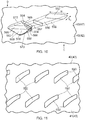
Figure 10 is a further enlarged perspective view of another recess in the second surface of the cooled combustion chamber wall shown infigure 3 . -
Figure 11 is a view in the direction of arrow C inFigure 10 looking at the first surface of the cooled combustion chamber wall. -
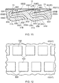
Figure 12 is a view in the direction of arrow D inFigure 10 looking at the second surface of the cooled combustion chamber wall. -
Figure 13 is an alternative view in the direction of arrow D inFigure 10 looking at the second surface of the cooled combustion chamber wall. -
Figure 14 is another alternative view in the direction of arrow D inFigure 10 looking at the second surface of the cooled combustion chamber wall. -
Figure 15 is a longitudinal cross-sectional view of an alternative cooled combustion chamber wall with a thermal barrier coating on the second surface. -
Figure 16 is an enlarged cross-sectional view of an alternative cooled combustion chamber wall according to the present disclosure. -
Figure 17 is a perspective view of cooled turbine blade according to the present disclosure. -
Figure 18 is a perspective view of a cooled turbine vane according to the present disclosure. - A turbofan
gas turbine engine 10, as shown infigure 1 , comprises in flow series an intake 11, afan 12, an intermediate pressure compressor 13, ahigh pressure compressor 14, acombustion chamber 15, a high pressure turbine 16, an intermediate pressure turbine 17, alow pressure turbine 18 and anexhaust 19. The high pressure turbine 16 is arranged to drive thehigh pressure compressor 14 via afirst shaft 26. The intermediate pressure turbine 17 is arranged to drive the intermediate pressure compressor 13 via asecond shaft 28 and thelow pressure turbine 18 is arranged to drive thefan 12 via athird shaft 30. In operation air flows into the intake 11 and is compressed by thefan 12. A first portion of the air flows through, and is compressed by, the intermediate pressure compressor 13 and thehigh pressure compressor 14 and is supplied to thecombustion chamber 15. Fuel is injected into thecombustion chamber 15 and is burnt in the air to produce hot exhaust gases which flow through, and drive, the high pressure turbine 16, the intermediate pressure turbine 17 and thelow pressure turbine 18. The hot exhaust gases leaving thelow pressure turbine 18 flow through theexhaust 19 to provide propulsive thrust. A second portion of the air bypasses the main engine to provide propulsive thrust. - The
combustion chamber 15, as shown more clearly infigure 2 , is an annular combustion chamber and comprises a radially innerannular wall 40, a radially outerannular wall structure 42 and anupstream end wall 44. The upstream end of the radially innerannular wall 40 is secured to the upstreamend wall structure 44 and the upstream end of the radially outerannular wall 42 is secured to theupstream end wall 44. Theupstream end wall 44 has a plurality of circumferentially spacedapertures 46 and eachaperture 46 has a respective one of a plurality offuel injectors 48 located therein. Thefuel injectors 48 are arranged to supply fuel into theannular combustion chamber 15 during operation of thegas turbine engine 10 and as mentioned above the fuel is burnt in air supplied into thecombustion chamber 15. - The radially inner
annular wall 40 and the radially outerannular wall 42 are cooled components of the turbofangas turbine engine 10. The radially innerannular wall 40 has afirst surface 41 and asecond surface 43 and similarly the radially outerannular wall 42 has afirst surface 45 and asecond surface 47. - The radially inner
annular wall 40 has a plurality ofeffusion cooling apertures 50 extending there-through from thefirst surface 41 towards thesecond surface 43, as shown more clearly infigures 3 to 8 . Theeffusion cooling apertures 50 are arranged at an angle α1 to thefirst surface 41 and to thesecond surface 43, as shown infigure 5 . Eachaperture 50 has aninlet 52 in thefirst surface 41 and anoutlet 54. Thesecond surface 43 has a plurality ofrecesses 58 and eachrecess 58 has anupstream end 60 and adownstream end 62, as shown infigure 3 . Eachrecess 58 has a planarupstream end surface 64 arranged at an angle α2 of more than 100° to thesecond surface 43 such that the planarupstream end surface 64 hangs over theupstream end 60 of therecess 58. Eachrecess 58 has a smoothlycurved transition 65 from the planarupstream end surface 64 to thesecond surface 43. Eachrecess 58 reduces in depth from theupstream end 60 of therecess 58 to thedownstream end 62 of therecess 58 and thus thebottom surface 59 of eachrecess 58 is also arranged at an angle α1 to thefirst surface 41 and to thesecond surface 43. Thebottom surface 59 of eachrecess 58 is thus arranged parallel to the correspondingeffusion cooling aperture 50, as shown infigure 5 . Eachrecess 58 has side surfaces 66 and 68 arranged at an angle α3 of less than 80° to thesecond surface 43 and eachrecess 58 has smoothlycurved transitions second surface 43. Thebottom surface 59 of eachrecess 58 is continuously curved between the side surfaces 66 and 68 of therecess 58, as shown infigure 6 . Eachrecess 58 has a depth D equal to the required depth DR plus the thickness T of athermal barrier coating 74 to be deposited on thesecond surface 43. The depth D is measured from thesecond surface 43 to thebottom surface 59 of therecess 58, as shown infigures 6 and 8 . - Each
effusion cooling aperture 50 as mentioned previously has aninlet 50 in thefirst surface 41 and theoutlet 54 is in a corresponding one of therecesses 58 in thesecond surface 43 and in particular eacheffusion cooling aperture 50 extends from thefirst surface 41 to the planarupstream end surface 64 of the corresponding one of therecesses 58 in thesecond surface 43. Eacheffusion cooling aperture 50 has ametering portion 56 between theinlet 52 and theoutlet 54, as clearly shown infigures 4 and 5 . - The side surfaces 66 and 68 of each
recess 58 converge from theupstream end 60 to thedownstream end 62 of therecess 58. Eachrecess 58 has a triangular shaped opening or a part elliptically shaped opening in thesecond surface 43, as shown infigures 3 and4 . - In this particular example each
recess 58 has a planarupstream end surface 64 arranged at an angle α2 of 105° to thesecond surface 43, eachrecess 58 has side surfaces 66 and 68 arranged at an angle α3 of 75° to thesecond surface 43, eacheffusion cooling aperture 50 has a circularcross-section metering portion 56 and eacheffusion cooling aperture 50 has an elliptically shapedinlet 52 in thefirst surface 42. - The
metering portion 56 of eacheffusion cooling aperture 50 is arranged at an angle α1 of between 10° and 30° to thefirst surface 41 and in this example themetering portion 56 of eacheffusion cooling aperture 50 is arranged at an angle α1 of 20° to thefirst surface 41. Themetering portion 56 of eacheffusion cooling apertures 50 has a diameter of 0.4mm. Thesecond surface 43 has athermal barrier coating 74 which has a thickness of 0.5mm. It is to be noted that theoutlet 54 of eacheffusion cooling aperture 50 is arranged in the planarupstream end surface 64 at a position such that it spaced from the bottom of theupstream end 60 of therecess 58 so that thethermal barrier coating 74 does not block theoutlet 54, e.g. the distance S from the centre of theoutlet 54 to thebottom surface 59 at theupstream end 60 of therecess 58 is at least equal to and preferably greater than the radius R of theoutlet 54 and the thickness T of thethermal barrier coating 74, as shown infigures 7 and8 . Thebottom surface 59 at theupstream end 60 of eachrecess 58 in this example is an arc of a circle with a radius S, seefigures 6 and 8 . - The
effusion cooling apertures 50 are arranged in longitudinally spaced rows and theapertures 50 in each row are laterally spaced apart and in particular theeffusion cooling apertures 50 are arranged in axially spaced rows and theapertures 50 in each row are circumferentially spaced apart. Theeffusion cooling apertures 50 in each row are offset laterally from theeffusion cooling apertures 50 in each adjacent row and in particular theeffusion cooling apertures 50 in each row are offset circumferentially from theeffusion cooling apertures 50 in each adjacent row. Thus, theeffusion cooling apertures 50 in thefirst surface 41 are arranged in axially spaced rows and theeffusion cooling apertures 50 in each row are circumferentially spaced apart. - The
recesses 58 are arranged in longitudinally spaced rows and therecesses 58 in each row are laterally spaced apart and in particular therecesses 58 are arranged in axially spaced rows and therecesses 58 in each row are circumferentially spaced apart. Therecesses 58 in each row are offset laterally from therecesses 58 in each adjacent row and in particular therecesses 58 in each row are offset circumferentially from therecesses 58 in each adjacent row. Thus, therecesses 58 in thesecond surface 43 are also arranged in axially spaced rows and therecesses 58 in each row are circumferentially spaced apart, as shown more clearly infigure 3 . - The
recesses 58 are arranged such that the planar upstream end surfaces 64 extend circumferentially of the radially innerannular wall 40 of theannular combustion chamber 15 and the side surfaces 66 and 68 extend substantially axially or with axial and circumferential components of the radially innerannular wall 40 of theannular combustion chamber 15. - The radially outer
annular wall 42 has a plurality ofeffusion cooling apertures 50 extending there-through from thefirst surface 41 towards thesecond surface 43 and a plurality ofrecesses 58 and each recess has anupstream end 60 and adownstream end 62, as shown more clearly infigures 3 to 8 and theseeffusion cooling apertures 50 and recesses 58 are arranged substantially the same as theeffusion cooling apertures 50 and recesses 58 in the radially innerannular wall 40. - In operation coolant, for example air supplied from the
high pressure compressor 14 of thegas turbine engine 10, flowing over the radially inner and outerannular walls effusion cooling apertures 50 from thefirst surface second surface annular walls effusion cooling apertures 50 exits theeffusion cooling apertures 50 and then flows over thesecond surfaces annular walls second surfaces annular walls outlets 54, in the planar upstream end surfaces 64 of therecesses 58, of theeffusion cooling apertures 50 and flows through therecesses 58 and onto thesecond surface annular walls -
Figure 9 shows a cooled component with an alternative effusion cooling aperture and recess. The radially innerannular wall 40 has a plurality ofeffusion cooling apertures 450 extending there-through from thefirst surface 41 towards thesecond surface 43. Theeffusion cooling apertures 450 are arranged at an angle α1 to thefirst surface 41 and to thesecond surface 43. Eachaperture 450 has aninlet 452 in thefirst surface 41 and anoutlet 454. Thesecond surface 43 has a plurality ofrecesses 458 and eachrecess 458 has anupstream end 460 and adownstream end 462. Eachrecess 458 has a planarupstream end surface 464 arranged at an angle α2 of more than 100° to thesecond surface 43 such that the planarupstream end surface 464 hangs over theupstream end 460 of therecess 458. Eachrecess 458 has a smoothlycurved transition 465 from the planarupstream end surface 464 to thesecond surface 43. Eachrecess 458 reduces in depth from theupstream end 460 of therecess 458 to thedownstream end 462 of therecess 458 and eachrecess 58 has a depth equal to the required depth plus the thickness of a thermal barrier coating to be deposited on thesecond surface 43. Eachrecess 458 hasside surfaces second surface 43 and eachrecess 458 has smoothlycurved transitions second surface 43. - Each
effusion cooling aperture 450 as mentioned previously has aninlet 450 in thefirst surface 41 and theoutlet 454 is in a corresponding one of therecesses 458 in thesecond surface 43 and in particular eacheffusion cooling aperture 450 extends from thefirst surface 41 to the planarupstream end surface 464 of the corresponding one of therecesses 458 in thesecond surface 43. - The side surfaces 466 and 468 of the
recesses 458 may diverge from theupstream end 460 to thedownstream end 462 of therecesses 458. The side surfaces 466 and 468 of eachrecess 458 may diverge from theupstream end 460 to thedownstream end 462 of therecess 458. Eachrecess 458 may having an isosceles trapezium shaped opening in thesecond surface 43. Alternatively, the side surfaces 466 and 468 of therecesses 458 may be parallel from theupstream end 460 to thedownstream end 462 of therecesses 458. The side surfaces 466 and 468 of eachrecess 458 may be parallel from theupstream end 460 to thedownstream end 462 of therecess 458. Eachrecess 458 may having a rectangular shaped opening in thesecond surface 43 or a square shaped opening in thesecond surface 43. - Each
effusion cooling aperture 450 has ametering portion 456 and a diffusingportion 457 arranged in flow series from theinlet 450 to theoutlet 454. Eacheffusion cooling aperture 450 diverges in thediffusion portion 457 from themetering portion 456 to theoutlet 454 in the planarupstream end surface 464 of therecess 458. - The
bottom surface 459 of eachrecess 458 is arranged parallel to the correspondingeffusion cooling aperture 450. Thebottom surface 459 of eachrecess 458 is planar and is curved to connect with the side surfaces 466 and 468 of therecess 458. - In this particular example each
recess 458 has a planarupstream end surface 464 arranged at an angle α2 of 105° to thesecond surface 43, eachrecess 458 hasside surfaces second surface 43, eacheffusion cooling aperture 450 has a circularcross-section metering portion 456 and eacheffusion cooling aperture 450 has an elliptically shapedinlet 452 in thefirst surface 42. Themetering portion 456 of eacheffusion cooling aperture 450 is arranged at an angle α1 of between 10° and 30° to thefirst surface 41 and in this example themetering portion 456 of eacheffusion cooling aperture 450 is arranged at an angle α1 of 20° to thefirst surface 41. Themetering portion 456 of eacheffusion cooling apertures 450 has a diameter of 0.4mm. Thesecond surface 43 has athermal barrier coating 74 which has a thickness of 0.5mm. It is to be noted that theoutlet 454 of eacheffusion cooling aperture 450 is arranged in the planarupstream end surface 464 at a position such that it spaced from the bottom of theupstream end 460 of therecess 458 so that thethermal barrier coating 74 does not block theoutlet 454, e.g. the distance S from the centre of theoutlet 454 to the bottom of theupstream end 460 of therecess 458 is at least equal to and preferably greater than the radius R of theoutlet 454 and the thickness T of thethermal barrier coating 74. - The
effusion cooling apertures 450 are arranged in longitudinally spaced rows and theapertures 450 in each row are laterally spaced apart and in particular theeffusion cooling apertures 450 are arranged in axially spaced rows and theapertures 450 in each row are circumferentially spaced apart. Theeffusion cooling apertures 450 in each row are offset laterally from theeffusion cooling apertures 450 in each adjacent row and in particular theeffusion cooling apertures 450 in each row are offset circumferentially from theeffusion cooling apertures 450 in each adjacent row. Thus, theeffusion cooling apertures 450 in thefirst surface 41 are arranged in axially spaced rows and theeffusion cooling apertures 450 in each row are circumferentially spaced apart. - The
recesses 458 are arranged in longitudinally spaced rows and therecesses 458 in each row are laterally spaced apart and in particular therecesses 458 are arranged in axially spaced rows and therecesses 458 in each row are circumferentially spaced apart. Therecesses 458 in each row are offset laterally from therecesses 458 in each adjacent row and in particular therecesses 458 in each row are offset circumferentially from therecesses 458 in each adjacent row. Thus, therecesses 458 in thesecond surface 43 are also arranged in axially spaced rows and therecesses 458 in each row are circumferentially spaced apart. - The
recesses 458 are arranged such that the planar upstream end surfaces 464 extend circumferentially of the radially innerannular wall 40 of theannular combustion chamber 15 and the side surfaces 466 and 468 extend substantially axially of the radially innerannular wall 40 or with axial and circumferential components of theannular combustion chamber 15. - The
effusion cooling apertures 450 and recesses 458 offigure 9 may also be provided in a combustion chamber tile, a combustion chamber heat shield, a combustion chamber segment, a turbine blade, a turbine vane or a turbine shroud. -
Figure 10 shows a cooled component with another alternative effusion cooling aperture and recess. Thesecond surface 43 has a plurality ofrecesses 558 and eachrecess 558 has anupstream end 560 and adownstream end 562. Theeffusion cooling aperture 550 andrecess 558 are substantially the same as that shown infigure 9 , but theeffusion cooling aperture 550 comprises anelongate metering portion 556 and the width W is greater than the length L1 of themetering portion 556. Eachaperture 550 has ametering portion 556 and a diffusingportion 557 arranged in flow series. Eacheffusion cooling aperture 550 as mentioned previously has aninlet 552 in thefirst surface 41 and an outlet 554 in a corresponding one of therecesses 558 in thesecond surface 43 and in particular eacheffusion cooling aperture 550 extends from thefirst surface 41 to the planarupstream end surface 564 of the corresponding one of therecesses 558 in thesecond surface 43. Eachinlet 552 has an elongate shape in thefirst surface 41 of the innerannular wall 40 and theinlet 552 in thewall 40 is arranged substantially diagonally with respect to the opening of therecess 558 in the innerannular wall 40, as shown infigure 11 . Eachrecess 558 has a rectangular shaped opening in thesecond surface 43 of the innerannular wall 40, as shown infigure 12 . Eachaperture 550 effectively increases in dimension in length from theinlet 552 of themetering portion 556 in thefirst surface 41 to the opening of therecess 558 in thesecond surface 43. - Alternatively, each
recess 558A has an isosceles trapezium shaped opening in thesecond surface 43 of the innerannular wall 40, as shown infigure 13 . In a further alternative, eachrecess 558B has a rhombus shaped opening in thesecond surface 43 of the innerannular wall 40, as shown infigure 14 . -
Figure 15 shows a cooled component with another alternative effusion cooling aperture and recess. Thesecond surface 43 has a plurality ofrecesses 658 and eachrecess 658 has anupstream end 660 and a downstream end 662. Theeffusion cooling aperture 650 andrecess 658 are substantially the same as that shown infigure 9 , but theeffusion cooling aperture 650 comprises anelongate metering portion 656 and the width W is greater than the length L1 of themetering portion 656. Eachaperture 650 has ametering portion 656 and a diffusing portion 657 arranged in flow series. Eacheffusion cooling aperture 650 as mentioned previously has aninlet 652 in thefirst surface 41 and theoutlet 654 is in a corresponding one of therecesses 658 in thesecond surface 43 and in particular eacheffusion cooling aperture 650 extends from thefirst surface 41 to the planarupstream end surface 664 of the corresponding one of therecesses 658 in thesecond surface 43. Eachinlet 652 has an elongate shape in thefirst surface 41 of the innerannular wall 40 and theinlet 652 in thewall 40 is arranged substantially diagonally with respect to the outlet of therecess 658 in the innerannular wall 40, similar to that shown infigure 11 . Eachrecess 658 has a rectangular shaped opening in thesecond surface 43 of the innerannular wall 40, similar to that shown infigure 12 . Eachaperture 650 effectively increases in dimension in length from theinlet 652 of themetering portion 656 in thefirst surface 41 to the opening of therecess 658 in thesecond surface 43. - The
metering portion 656 of eacheffusion cooling aperture 650 comprises aninlet portion 656A, a longitudinallyupstream extending portion 656B, aU-shaped bend portion 656C and a longitudinallydownstream extending portion 656D, as shown infigure 15 . The longitudinallydownstream extending portion 656D is connected to theoutlet 654 into therecess 658 of theeffusion cooling aperture 650. The longitudinallyupstream extending portion 656B and the longitudinallydownstream extending portion 656D are substantially parallel. The longitudinallyupstream extending portion 656B and the longitudinallydownstream extending portion 656D of themetering portion 656 and thebottom surface 659 of therecess 658 are substantially parallel. - It is to be noted that the
inlet 652 of eacheffusion cooling aperture 650 is arranged substantially diagonally, extending with lateral, circumferential, and longitudinal, axial, components and the opening of eachrecess 658 in thesecond surface 43 is rectangular in shape. Themetering portion 656 of eacheffusion cooling aperture 650 gradually changes theeffusion cooling aperture 650 from the diagonal alignment at theinlet 652 to a rectangular shape at the junction between theinlet portion 656A and the longitudinallyupstream extending portion 656B. The gradual changes in theeffusion cooling aperture 650 between the diagonal alignment to the rectangular shape at the junction between theinlet portion 656A and the longitudinallyupstream extending portion 656B and therecess 658 are preferably designed to be aerodynamic. The opening of therecess 658 is designed to aerodynamically blend to the second surface 53. - The
first surface 41 of the radially innerannular wall 40 is provided with a plurality of rows ofbulges 41A, thebulges 41A in each row are laterally, circumferentially, spaced and the rows ofbulges 41A are longitudinally, axially, spaced on the radially innerannular wall 40. Thebulges 41A are localised regions where thefirst surface 41 of the radially innerannular wall 40 is curved to a maximum distance from thesecond surface 43 of the radially innerannular wall 40. TheU-shaped bend portion 656C of themetering portion 56 of eacheffusion cooling aperture 650 is aligned laterally, circumferentially, and longitudinally, axially, with a corresponding one of thebulges 41A in thefirst surface 41. In particular the junction between the longitudinallyupstream extending portion 656B and theU-shaped bend portion 656C of eacheffusion cooling aperture 650 is aligned longitudinally, axially, with the point of an associatedbulge 41A which is at a maximum distance from thesecond surface 43 of the radially innerannular wall 40. The U-bend shapedportion 656C of eacheffusion cooling aperture 650 is the most upstream portion of theeffusion cooling aperture 650. The longitudinallyupstream extending portion 656B of eacheffusion cooling aperture 650 is arranged substantially parallel with aportion 41 B of thefirst surface 41 of the radially innerannular wall 40 between thebulge 41A aligned with the junction between the longitudinallyupstream extending portion 656B and theU-shaped bend portion 656C of thateffusion cooling aperture 650 and theinlet 652 of thateffusion cooling aperture 650. - Alternatively, the
first surface 41 of the radially innerannular wall 40 is corrugated and thecorrugations 41A are longitudinally, axially, spaced and thecorrugations 41A extend laterally, circumferentially, of the radially innerannular wall 40. Thecorrugations 41A are regions where thefirst surface 41 of the radially innerannular wall 40 is curved to a maximum distance from thesecond surface 43 of the radially innerannular wall 40. TheU-shaped bend portion 656C of themetering portion 656 of eacheffusion cooling aperture 650 is aligned longitudinally, axially, with a corresponding one of thecorrugations 41A in thefirst surface 41. In particular the junction between the longitudinallyupstream extending portion 656B and theU-shaped bend portion 656C of eacheffusion cooling aperture 650 is aligned longitudinally, axially, with the point of an associatedcorrugation 41A which is at a maximum distance from thesecond surface 43 of the radially innerannular wall 40. The U-bend shapedportion 656C of eacheffusion cooling aperture 650 is the most upstream portion of theeffusion cooling aperture 650. The longitudinallyupstream extending portion 656B of eacheffusion cooling aperture 650 is arranged substantially parallel with aportion 41 B of thefirst surface 41 of the radially innerannular wall 40 between thecorrugation 41A aligned with the junction between the longitudinally upstream extending portion 56B and theU-shaped bend portion 656C of thateffusion cooling aperture 650 and theinlet 652 of thateffusion cooling aperture 650. - The
U-shaped bend portion 656B of eacheffusion cooling aperture 650 has a curved upstream end wall and the curved upstream surface is convex so as to enable theeffusion cooling aperture 650 to be manufactured by additive layer manufacturing. TheU-shaped bend portion 656B of eacheffusion cooling aperture 650 also has a curved downstream end wall and the curved downstream surface is concave so as to enable theeffusion cooling aperture 650 to be manufactured by additive layer manufacturing. The laterally spaced end walls of eachU-shaped bend portion 656B of eacheffusion cooling aperture 650 may be planar or may be curved. The laterally spaced end walls of themetering portion 656 of eacheffusion cooling aperture 650 may be planar or may be curved, e.g. concave. - It is to be noted that the
inlet 652 of eacheffusion cooling aperture 650 is axially downstream of theU-shaped bend portion 656B of themetering portion 656 of theeffusion cooling aperture 650 and theoutlet 654 of eacheffusion cooling aperture 650 is axially downstream of theU-shaped bend portion 656B of themetering portion 656 of theeffusion cooling aperture 650. - Alternatively, each
recess 658 may have an isosceles trapezium shaped opening in the second surface of the inner annular wall, similar to that shown infigure 13 . In a further alternative, eachrecess 658 may have a rhombus shaped opening in the second surface of the inner annular wall, similar to that shown infigure 14 . - Another
combustion chamber 115, as shown more clearly infigure 16 , is an annular combustion chamber and comprises a radially innerannular wall structure 140, a radially outer annular wall structure 142 and an upstream end wall structure 144. The radially innerannular wall structure 140 comprises a firstannular wall 146 and a secondannular wall 148. The radially outer annular wall structure 142 comprises a thirdannular wall 150 and a fourthannular wall 152. The secondannular wall 148 is spaced radially from and is arranged radially around the firstannular wall 146 and the firstannular wall 146 supports the secondannular wall 148. The fourthannular wall 152 is spaced radially from and is arranged radially within the thirdannular wall 150 and the thirdannular wall 150 supports the fourthannular wall 152. The upstream end of the firstannular wall 146 is secured to the upstream end wall structure 144 and the upstream end of the thirdannular wall 150 is secured to the upstream end wall structure 144. The upstream end wall structure 144 has a plurality of circumferentially spacedapertures 154 and eachaperture 154 has a respective one of a plurality offuel injectors 156 located therein. Thefuel injectors 156 are arranged to supply fuel into theannular combustion chamber 115 during operation of thegas turbine engine 10. - The second
annular wall 148 comprises a plurality of rows ofcombustor tiles annular wall 152 comprises a plurality of rows ofcombustor tiles combustor tiles combustor tiles annular wall 146 and thecombustor tiles combustor tiles annular wall 150. - The
combustor tiles gas turbine engine 10. Each of thecombustor tiles first surface 41 and asecond surface 43. Thecombustion chamber tiles combustion chamber wall 140 and 142 and eachcombustion chamber tile figures 3 to 8 , effusion cooling apertures and recesses as shown infigure 9 , effusion cooling apertures and recesses as shown infigures 10 to 14 or effusion cooling apertures and recesses as shown infigures 11 to 15 . - Each
combustion chamber tile recess 58 arranged such that the planar upstream end surfaces 64 which extend laterally extend circumferentially of thecombustion chamber tile combustion chamber tile recesses 58 are arranged in axially spaced rows and therecesses 58 in each row are circumferentially spaced apart. Theeffusion cooling apertures 50 are arranged in axially spaced rows and theapertures 50 in each row are circumferentially spaced apart. Therecesses 58 in each row are offset circumferentially from therecesses 58 in each adjacent row. Theeffusion cooling apertures 50 in each row are offset circumferentially from theeffusion cooling apertures 50 in each adjacent row. - The first
annular wall 146 and the thirdannular wall 150 are provided with a plurality of impingement cooling apertures extending there-through to direct coolant onto thefirst surfaces 41 of thecombustor tiles - In operation coolant, for example air supplied from the
high pressure compressor 14 of thegas turbine engine 10, flowing over the radially inner and outerannular wall structures 140 and 142 respectively is supplied through the impingement cooling apertures in the first and thirdannular walls first surfaces 41 of thecombustor tiles annular walls combustor tiles effusion cooling apertures 50 in thecombustor tiles annular walls first surface 41 to thesecond surface 43 of thecombustor tiles annular walls annular wall structures 140 and 142 respectively. The flow of coolant through theeffusion cooling apertures 50 exits theeffusion cooling apertures 50 and then flows over thesecond surfaces 43 of thecombustor tiles annular walls annular wall structures 140 and 142 respectively to form a film of coolant on thesecond surfaces 43 of thecombustor tiles annular walls annular wall structures 140 and 142 respectively. In particular the flow of coolant exits theoutlets 54, in the planar upstream end surfaces 64 of therecesses 58, of theeffusion cooling apertures 50 and flows through therecesses 58 and onto thesecond surfaces 43 of thecombustor tiles annular walls annular wall structures 140 and 142 respectively. - If the effusion cooling apertures on the
combustor tiles figure 15 , some of the impingement cooling apertures in the first and thirdannular walls bulges 41A, or corrugations, 41A on thefirst surface 41 to increase heat removal from thefirst surface 41. - In another arrangement, not shown, an annular combustion chamber wall comprises a plurality of wall segments and each of the combustion chamber wall segments is a cooled component of the gas turbine engine. Each combustion chamber wall segment comprises an outer wall and an inner wall spaced from the inner wall, the outer wall has a plurality of impingement cooling apertures and the inner wall has a plurality of effusion cooling apertures and a plurality of recesses. The inner wall of each combustion chamber wall segment has each recess arranged such that the planar upstream end surfaces which extend laterally extend circumferentially of the combustion chamber segment and the side surfaces which extend longitudinally extend axially of the combustion chamber segment. The recesses are arranged in axially spaced rows and the recesses in each row are circumferentially spaced apart. The effusion cooling apertures are arranged in axially spaced rows and the apertures in each row are circumferentially spaced apart. The recesses in each row are offset laterally from the recesses in each adjacent row. The effusion cooling apertures in each row are offset circumferentially from the effusion cooling apertures in each adjacent row. The combustion chamber wall segment has effusion cooling apertures and recesses as shown in
figures 3 to 8 , effusion cooling apertures and recesses as shown infigure 9 , effusion cooling apertures and recesses as shown infigures 10 to 14 or effusion cooling apertures and recesses as shown infigures 11 to 15 . - A
turbine blade 200, as shown more clearly infigure 17 , comprises aroot portion 202, ashank portion 204, aplatform portion 206 and anaerofoil portion 208. Theaerofoil portion 208 has aleading edge 210, a trailingedge 212,convex wall 214 and aconcave wall 216 and the convex andconcave walls leading edge 210 to the trailingedge 212. Theturbine blade 200 is hollow and has a plurality of passages formed therein and is a cooled component of thegas turbine engine 10. The cooledturbine blade 200 has a plurality ofeffusion cooling apertures 50 extending through the convex andconcave walls aerofoil portion 208 to cool theaerofoil portion 208 of theturbine blade 200. The cooledturbine blade 200 has eachrecess 58 arranged such that the planar upstream end surfaces 64 which extend laterally extend radially of theturbine blade 200 and the side surfaces 66 and 68 which extend longitudinally extend axially of theturbine blade 200. Therecesses 58 are arranged in axially spaced rows and therecesses 58 in each row are radially spaced apart. Theeffusion cooling apertures 50 are arranged in axially spaced rows and theapertures 50 in each row are radially spaced apart. Therecesses 58 in each row are offset radially from therecesses 58 in each adjacent row. Theeffusion cooling apertures 50 in each row are offset radially from theeffusion cooling apertures 50 in each adjacent row. Theturbine blade 200 has effusion cooling apertures and recesses as shown infigures 3 to 8 , effusion cooling apertures and recesses as shown infigure 9 , effusion cooling apertures and recesses as shown infigures 10 to 14 or effusion cooling apertures and recesses as shown infigures 11 to 15 . - In operation coolant, for example air supplied from the
high pressure compressor 14 of thegas turbine engine 10, is supplied into the passages within theturbine blade 200 and the coolant flows through theeffusion cooling apertures 50 from thefirst surface 41 to thesecond surface 43 of the convex andconcave walls aerofoil portion 208. The flow of coolant through theeffusion cooling apertures 50 exits theeffusion cooling apertures 50 and then flows over thesecond surfaces 43 of the convex andconcave walls aerofoil portion 208 to form a film of coolant on thesecond surfaces 43 of the convex andconcave walls aerofoil portion 208. In particular the flow of coolant exits theoutlets 54, in the planar upstream end surfaces 64 of therecesses 58, of theeffusion cooling apertures 50 and flows through therecesses 58 and onto thesecond surfaces 43 of theturbine blade 200. - A
turbine vane 300, as shown more clearly infigure 18 , comprises aninner platform portion 302, anaerofoil portion 304 and anouter platform portion 306. Theaerofoil portion 304 has aleading edge 308, a trailingedge 310,convex wall 312 and aconcave wall 314 and the convex andconcave walls leading edge 308 to the trailingedge 310. Theturbine vane 300 is hollow and has a plurality of passages formed therein and is a cooled component of thegas turbine engine 10. The cooledturbine vane 300 has a plurality ofeffusion cooling apertures 50 extending through the convex andconcave walls aerofoil portion 304 to cool theaerofoil portion 304 of theturbine vane 300. The cooledturbine vane 300 has eachrecess 58 arranged such that the planar upstream end surfaces 64 which extend laterally extend radially of theturbine vane 300 and the side surfaces 66 and 68 which extend longitudinally extend axially of theturbine vane 300. Therecesses 58 are arranged in axially spaced rows and therecesses 58 in each row are radially spaced apart. Theeffusion cooling apertures 50 are arranged in axially spaced rows and theapertures 50 in each row are radially spaced apart. Therecesses 58 in each row are offset radially from therecesses 58 in each adjacent row. Theeffusion cooling apertures 50 in each row are offset radially from theeffusion cooling apertures 50 in each adjacent row. Theturbine vane 300 has effusion cooling apertures and recesses as shown infigures 3 to 8 , effusion cooling apertures and recesses as shown infigure 9 , effusion cooling apertures and recesses as shown infigures 10 to 14 or effusion cooling apertures and recesses as shown infigures 11 to 15 . - In operation coolant, for example air supplied from the
high pressure compressor 14 of thegas turbine engine 10, is supplied into the passages within theturbine vane 300 and the coolant flows through theeffusion cooling apertures 50 from thefirst surface 41 to thesecond surface 43 of the convex andconcave walls aerofoil portion 304. The flow of coolant through theeffusion cooling apertures 50 exits theeffusion cooling apertures 50 and then flows over thesecond surfaces 43 of the convex andconcave walls aerofoil portion 304 to form a film of coolant on thesecond surfaces 43 of the convex andconcave walls aerofoil portion 304. In particular the flow of coolant exits theoutlets 54, in the planar upstream end surfaces 64 of therecesses 58, of theeffusion cooling apertures 50 and flows through therecesses 58 and onto thesecond surfaces 43 of theturbine vane 300. - The
turbine blade 200 may additionally have effusion cooling apertures and recesses in theplatform portion 206 and/or theturbine vane 300 may additionally have effusion cooling apertures and recesses in the inner and/orouter platform portions - In any of the embodiments discussed above, the cooled component may comprise a second wall, the second wall being spaced from the first surface of the wall, the second wall having a third surface and a fourth surface, the fourth surface of the second wall being spaced from the first surface of the wall and the second wall having a plurality of impingement cooling apertures extending there-through from the third surface to the fourth surface.
- It is to be noted that the effusion cooling apertures are inclined in the direction of flow of the hot gases over the cooled component.
- The cooled components, the cooled combustor chamber wall, the cooled combustion chamber combustor tile, the cooled combustion chamber heat shield, the cooled combustion chamber wall segment, the cooled turbine blade, the cooled turbine vane or cooled turbine shroud are preferably formed by additive layer manufacturing, for example direct laser deposition, selective laser sintering or direct electron beam deposition. The cooled component is built up layer by layer using additive layer manufacturing in the longitudinal, axial, direction of the wall which corresponds to the direction of flow of hot gases over the second surface of the wall.
- The cooled combustion chamber walls may be manufactured by direct laser deposition in a powder bed by producing a spiral shaped wall sintering the powder metal layer by layer, (in the longitudinal, axial, direction of the wall) and then unravelling and welding, bonding, brazing or fastening the ends of what was the spiral shaped wall together to form an annular combustion chamber wall. The combustion chamber tiles may be manufactured by direct laser deposition in a powder bed by sintering the powder metal layer by layer in the longitudinal, axial, direction of the combustion chamber tile. The combustion chamber segments may be manufactured by direct laser deposition in a powder bed by sintering the powder metal layer by layer in the longitudinal, axial, direction of the combustion chamber tile.
- The cooled components, the cooled combustor chamber wall, the cooled combustion chamber combustor tile, the cooled combustion chamber heat shield, the cooled combustion chamber wall segment, the cooled turbine blade, the cooled turbine vane or cooled turbine shroud may be formed by casting and the effusion cooling apertures and recesses may be formed by laser drilling, electro-discharge machining or electro-chemical machining. The cooled components, the cooled combustor chamber wall, the cooled combustion chamber combustor tile, the cooled combustion chamber heat shield, the cooled combustion chamber wall segment, the cooled turbine blade, the cooled turbine vane or cooled turbine shroud with recesses in the second surface may be formed by casting and the effusion cooling apertures may be formed by laser drilling, electro-discharge machining or electro-chemical machining.
- The cooled components comprise a superalloy, for example a nickel, or cobalt, superalloy. The thermal barrier coating may comprise a ceramic coating or a metallic bond coating and a ceramic coating. The ceramic coating may comprise zirconia, for example stabilised zirconia, e.g. yttria stabilised zirconia, ceria stabilised zirconia, yttria and erbia stabilised zirconia etc. The metallic bond coating may comprise an aluminide coating, e.g. a platinum aluminide coating, a chromium aluminide coating, a platinum chromium aluminide coating, a silicide aluminide coating or a MCrAlY coating where M is one or more of iron, nickel and cobalt, Cr is chromium, Al is aluminium and Y is a rare earth metal, e.g. yttrium, lanthanum etc.
- The cooled component may be a turbine blade, a turbine vane, a combustion chamber wall, a combustion chamber tile, a combustion chamber heat shield, a combustion chamber wall segment or a turbine shroud.
- The cooled component may be a gas turbine engine component or other turbomachine component, e.g. a steam turbine, or an internal combustion engine etc.
- The gas turbine engine may be an aero gas turbine engine, an industrial gas turbine engine, a marine gas turbine engine or an automotive gas turbine engine. The aero gas turbine engine may be a turbofan gas turbine engine, a turbo-shaft gas turbine engine, a turbo-propeller gas turbine engine or a turbojet gas turbine engine.
- Thus, in each of the embodiments described above each recess is arranged such that the planar upstream end surface extends laterally and the side surfaces extend longitudinally. The recesses are arranged in longitudinally spaced rows and the recesses in each row are laterally spaced apart. The effusion cooling apertures are arranged in longitudinally spaced rows and the apertures in each row are laterally spaced apart. The recesses in each row are offset laterally from the recesses in each adjacent row. The effusion cooling apertures in each row are offset laterally from the effusion cooling apertures in each adjacent row.
- The advantage of the present disclosure is that the recesses and effusion cooling apertures are arranged such that a thermal barrier coating subsequently applied onto the second surface minimises, or avoids, blockage of the effusion cooling apertures and minimises aerodynamic disturbance of the coolant flow through the effusion cooling apertures. The present disclosure allows a thermal barrier coating to be applied to the second surface of the component after the effusion cooling apertures have been formed with minimum blockage of the effusion cooling apertures and minimum aerodynamic disturbance of the coolant flow through the effusion cooling apertures. Each recess and associated effusion cooling aperture is arranged such that the recess has a depth equal to the required finished depth of the recess plus the thickness of the thermal barrier coating. Each recess is provided with a planar upstream end surface and the outlet of the associated effusion cooling aperture is provided in the planar upstream end surface. Each recess and associated effusion cooling aperture is arranged so that the planar upstream end surface hangs over the upstream end of the recess such that the outlet of the associated effusion cooing aperture is shadowed by the overhang and blockage of the outlet of the effusion cooling apertures is minimised, or avoided. Each recess has a smoothly curved transition from the planar upstream end surface to the second surface to minimise, or avoid, the thermal barrier coating, "snow-drifting", building up over the outlet of the associated effusion cooling aperture. Each recess has side surfaces angled to the second surface and each recess has smoothly curved transitions from the side surfaces to the second surface to minimise, or avoid, the thermal barrier coating, "snow-drifting", building up over the side surfaces of the recess which creates a thermal barrier coating with non-uniform thickness and furthermore creates un-aerodynamic edges which disrupt the coolant flow exiting the effusion cooling aperture. The effusion cooling apertures with a diffusion portion have additional advantages in that the diffusing portion is within the body of the cooled component leading to the outlet in the planar upstream end surface and is thus defined by the cooled component and is not defined by the thickness of the thermal barrier coating. If thermal barrier coating were to enter the outlet of the effusion cooling aperture then only the diffusing portion of the effusion cooling aperture is partially blocked and not the metering portion of the effusion cooling aperture. Thus, there is minimal effusion cooling aperture blockage, the depth of the recess may be tailored to match the thickness of the thermal barrier coating, component cost and inspection cost are reduced, the thermal barrier coating has a more uniform thickness, the working life of the cooled component is increased due to reduced thermal barrier coating loss and to more uniform thermal barrier coating thickness and there is improved aerodynamic interface between the effusion cooing apertures and the thermal barrier coating.
- Althogh the present disclosure has referred to effusion cooling apertures with circular cross-sectional metering portions it is also applicable to effusion cooling apertures with other cross-sectional shapes of metering portions, e.g. elliptical, slots, fanned. Although the present disclosure has been described with reference to recesses with rectangular shape, square shape, isosceles trapezium shape and rhombus shape outlet in the surface of the component it may be possible to use parallelogram shapes or any other suitable quadrilateral shape.
- While the present invention has been illustrated by a description of various embodiments and while these embodiments have been described in considerable detail, it is not the intention of the applicants to restrict or in any way limit the scope of the appended claims to such detail. Additional advantages and modifications will readily appear to those skilled in the art. Accordingly, departures may be made from such details without departing from the scope of applicant's general inventive concept.
Claims (20)
- A cooled component comprising a wall (40) having a first surface (41) and a second surface (43), the second surface (43) having a plurality of recesses (58), each recess (58) having an upstream end (60) and a downstream end (62), each recess (58) having a planar upstream end surface (64) arranged at an angle (α2) of more than 100° to the second surface (43) such that the planar upstream end surface (64) hangs over the upstream end (60) of the recess (58), each recess (58) reducing in depth from the upstream end (60) of the recess (58) to the downstream end (62) of the recess (58), the wall (40) having a plurality of effusion cooling apertures (50) extending there-through from the first surface (41) towards the second surface (43), the effusion cooling apertures (50) being arranged at an angle (α1) to the first surface (41), each effusion cooling aperture (50) having an inlet (52) in the first surface (41), characterised in:each recess (58) having a smoothly curved transition (65) from the planar upstream end surface (64) to the second surface (43),each recess (58) having side surfaces (66, 68) arranged at an angle (α3) of less than 80° to the second surface (43) and each recess (58) having smoothly curved transitions (70, 72) from the side surfaces (66, 68) to the second surface (43),
each effusion cooling aperture (50) having an outlet (54) in the planar upstream surface (64) of a corresponding one of the recesses (58) in the second surface (43), and
each effusion cooling aperture (50) extending from the first surface (41) to the planar upstream end surface (64) of the corresponding one of the recesses (58) in the second surface (43). - A cooled component as claimed in claim 1 wherein the side surfaces (66, 68) of each recess (58) converge from the upstream end (60) to the downstream end (62) of the recess (58).
- A cooled component as claimed in claim 2 wherein each recess (58) has a triangular shaped opening in the second surface (43) or a part elliptically shaped opening in the second surface (43).
- A cooled component as claimed in claim 1 wherein the side surfaces (466, 468) of each recess (458) diverge from the upstream end (460) to the downstream end (462) of the recess (458).
- A cooled component as claimed in claim 4 wherein each recess (458) has an isosceles trapezium shaped opening in the second surface (43).
- A cooled component as claimed in claim 1 wherein the side surfaces (466, 468) of each recess (458) are parallel from the upstream end (460) to the downstream end (462) of the recess (458).
- A cooled component as claimed in claim 6 wherein each recess (458, 558, 558B) has a rectangular shaped opening, a square shaped opening or a rhombus shaped opening in the second surface (43).
- A cooled component as claimed in any of claims 1 to 7 wherein each effusion cooling aperture (50) has a metering portion (56) between the inlet (52) and the outlet (54).
- A cooled component as claimed in any of claims 1 to 8 wherein each effusion cooling aperture (450) has a metering portion (456) and a diffusing portion (457) arranged in flow series between the inlet (452) and the outlet (454).
- A cooled component as claimed in any of claims 1 to 9 wherein the bottom (59) of each recess (58) is arranged parallel to the corresponding effusion cooling aperture (50).
- A cooled component as claimed in any of claims 1 to 10 wherein each recess (58) has a planar upstream end surface (64) arranged at an angle of 105° to the second surface (43).
- A cooled component as claimed in any of claims 1 to 11 wherein each recess (58) has side surfaces (66, 68) arranged at an angle of 75° to the second surface (43).
- A cooled component as claimed in any of claims 1 to 12 wherein each effusion cooling aperture (50) has an elliptically shaped inlet (52) in the first surface (41).
- A cooled component as claimed in any of claims 1 to 13 wherein each effusion cooling aperture (50) has a circular cross-section metering portion (56).
- A cooled component as claimed in any of claims 1 to 14 wherein each effusion cooling aperture (450) diverges in the diffusion portion (457).
- A cooled component as claimed in claim 8 or claim 9 wherein the metering portion (56) is arranged at an angle (α1) of between 10° and 30° to the first surface (41).
- A cooled component as claimed in any of claims 1 to 16 wherein the cooled component has a thermal barrier coating (74) on the second surface (43), each recess (58) having a depth (D) equal to the required depth (DR) plus the thickness (T) of the thermal barrier coating (74) to be deposited.
- A cooled component as claimed in any of claims 1 to 17 wherein the cooled component comprises a second wall, the second wall having a third surface and a fourth surface, the fourth surface of the second wall being spaced from the first surface of the wall and the second wall having a plurality of impingement cooling apertures extending there-through from the third surface to the fourth surface.
- A cooled component as claimed in any of claims 1 to 18 wherein the cooled component is a turbine blade (200), a turbine vane (300), a combustion chamber wall (40, 42), a combustion chamber tile (148A, 148B, 152A, 152B), a combustion chamber heat shield, a combustion chamber wall segment or a turbine shroud.
- A cooled component as claimed in any of claims 1 to 19 wherein the cooled component is manufactured by additive layer manufacturing.
Applications Claiming Priority (1)
| Application Number | Priority Date | Filing Date | Title |
|---|---|---|---|
| GBGB1419327.0A GB201419327D0 (en) | 2014-10-30 | 2014-10-30 | A cooled component |
Publications (2)
| Publication Number | Publication Date |
|---|---|
| EP3015648A1 EP3015648A1 (en) | 2016-05-04 |
| EP3015648B1 true EP3015648B1 (en) | 2017-08-23 |
Family
ID=52118435
Family Applications (1)
| Application Number | Title | Priority Date | Filing Date |
|---|---|---|---|
| EP15187835.2A Active EP3015648B1 (en) | 2014-10-30 | 2015-10-01 | Cooled component |
Country Status (3)
| Country | Link |
|---|---|
| US (1) | US9957811B2 (en) |
| EP (1) | EP3015648B1 (en) |
| GB (1) | GB201419327D0 (en) |
Families Citing this family (23)
| Publication number | Priority date | Publication date | Assignee | Title |
|---|---|---|---|---|
| DE102013214487A1 (en) * | 2013-07-24 | 2015-01-29 | Rolls-Royce Deutschland Ltd & Co Kg | Combustor shingle of a gas turbine |
| EP3967854B1 (en) * | 2013-11-25 | 2023-07-05 | Raytheon Technologies Corporation | Assembly for a turbine engine |
| US20160230993A1 (en) * | 2015-02-10 | 2016-08-11 | United Technologies Corporation | Combustor liner effusion cooling holes |
| CA2933884A1 (en) * | 2015-06-30 | 2016-12-30 | Rolls-Royce Corporation | Combustor tile |
| GB201511776D0 (en) * | 2015-07-06 | 2015-08-19 | Rolls Royce Plc | Manufacture of component with cooling channels |
| GB201521077D0 (en) | 2015-11-30 | 2016-01-13 | Rolls Royce | A cooled component |
| US10876407B2 (en) * | 2017-02-16 | 2020-12-29 | General Electric Company | Thermal structure for outer diameter mounted turbine blades |
| US10895157B2 (en) * | 2017-04-24 | 2021-01-19 | Honeywell International Inc. | Gas turbine engine components with air-cooling features, and related methods of manufacturing the same |
| DE102017216595A1 (en) | 2017-09-19 | 2019-03-21 | Rolls-Royce Deutschland Ltd & Co Kg | Engine component with at least one cooling hole |
| US11402096B2 (en) * | 2018-11-05 | 2022-08-02 | Rolls-Royce Corporation | Combustor dome via additive layer manufacturing |
| US11085641B2 (en) | 2018-11-27 | 2021-08-10 | Honeywell International Inc. | Plug resistant effusion holes for gas turbine engine |
| US10822958B2 (en) | 2019-01-16 | 2020-11-03 | General Electric Company | Component for a turbine engine with a cooling hole |
| US11306659B2 (en) * | 2019-05-28 | 2022-04-19 | Honeywell International Inc. | Plug resistant effusion holes for gas turbine engine |
| WO2020246494A1 (en) | 2019-06-07 | 2020-12-10 | 株式会社Ihi | Film cooling structure, and turbine blade for gas turbine engine |
| US11486578B2 (en) | 2020-05-26 | 2022-11-01 | Raytheon Technologies Corporation | Multi-walled structure for a gas turbine engine |
| US11585224B2 (en) | 2020-08-07 | 2023-02-21 | General Electric Company | Gas turbine engines and methods associated therewith |
| US11428160B2 (en) | 2020-12-31 | 2022-08-30 | General Electric Company | Gas turbine engine with interdigitated turbine and gear assembly |
| CN113107612A (en) * | 2021-04-28 | 2021-07-13 | 浙江意动科技股份有限公司 | Air film hole turbine blade with turning angle |
| US11674686B2 (en) * | 2021-05-11 | 2023-06-13 | Honeywell International Inc. | Coating occlusion resistant effusion cooling holes for gas turbine engine |
| US11965653B2 (en) | 2021-06-23 | 2024-04-23 | General Electric Company | Dilution air inlets with notched tip and slotted tail for combustor |
| US20230243265A1 (en) * | 2022-01-28 | 2023-08-03 | Raytheon Technologies Corporation | Ceramic matrix composite article and method of making the same |
| US11927111B2 (en) | 2022-06-09 | 2024-03-12 | General Electric Company | Turbine engine with a blade |
| US11898460B2 (en) | 2022-06-09 | 2024-02-13 | General Electric Company | Turbine engine with a blade |
Family Cites Families (24)
| Publication number | Priority date | Publication date | Assignee | Title |
|---|---|---|---|---|
| US4773593A (en) | 1987-05-04 | 1988-09-27 | United Technologies Corporation | Coolable thin metal sheet |
| US5771577A (en) | 1996-05-17 | 1998-06-30 | General Electric Company | Method for making a fluid cooled article with protective coating |
| US5902647A (en) | 1996-12-03 | 1999-05-11 | General Electric Company | Method for protecting passage holes in a metal-based substrate from becoming obstructed, and related compositions |
| US6383602B1 (en) | 1996-12-23 | 2002-05-07 | General Electric Company | Method for improving the cooling effectiveness of a gaseous coolant stream which flows through a substrate, and related articles of manufacture |
| DE59808269D1 (en) | 1998-03-23 | 2003-06-12 | Alstom Switzerland Ltd | Film cooling hole |
| DE59810031D1 (en) | 1998-09-10 | 2003-12-04 | Alstom Switzerland Ltd | Process for forming a film cooling hole |
| US6847004B2 (en) | 2003-01-10 | 2005-01-25 | General Electric Company | Process of removing a ceramic coating deposit in a surface hole of a component |
| US7328580B2 (en) | 2004-06-23 | 2008-02-12 | General Electric Company | Chevron film cooled wall |
| JP4931507B2 (en) * | 2005-07-26 | 2012-05-16 | スネクマ | Cooling flow path formed in the wall |
| EP1967696B1 (en) | 2005-11-01 | 2017-03-15 | IHI Corporation | Turbine part |
| US20080271457A1 (en) | 2007-05-01 | 2008-11-06 | General Electric Company | Cooling Holes For Gas Turbine Combustor Having A Non-Uniform Diameter Therethrough |
| FR2926481B1 (en) | 2008-01-23 | 2011-09-23 | Snecma | COOLING CHANNEL CLEANING IN A WALL |
| GB2461897B (en) | 2008-07-17 | 2010-11-03 | Rolls Royce Plc | Combustion apparatus |
| DE102009007164A1 (en) | 2009-02-03 | 2010-08-12 | Rolls-Royce Deutschland Ltd & Co Kg | A method of forming a cooling air opening in a wall of a gas turbine combustor and combustor wall made by the method |
| US8672613B2 (en) | 2010-08-31 | 2014-03-18 | General Electric Company | Components with conformal curved film holes and methods of manufacture |
| US20120102959A1 (en) | 2010-10-29 | 2012-05-03 | John Howard Starkweather | Substrate with shaped cooling holes and methods of manufacture |
| US20120167389A1 (en) | 2011-01-04 | 2012-07-05 | General Electric Company | Method for providing a film cooled article |
| JP2013167205A (en) | 2012-02-15 | 2013-08-29 | Hitachi Ltd | Gas turbine blade, and tool for electrical discharge machining and machining method of the same |
| GB201205011D0 (en) | 2012-03-22 | 2012-05-09 | Rolls Royce Plc | A thermal barrier coated article and a method of manufacturing a thermal barrier coated article |
| GB201205020D0 (en) | 2012-03-22 | 2012-05-09 | Rolls Royce Plc | A method of manufacturing a thermal barrier coated article |
| US9181809B2 (en) | 2012-12-04 | 2015-11-10 | General Electric Company | Coated article |
| US20140161585A1 (en) | 2012-12-10 | 2014-06-12 | General Electric Company | Turbo-machine component and method |
| US9328616B2 (en) * | 2013-02-01 | 2016-05-03 | Siemens Aktiengesellschaft | Film-cooled turbine blade for a turbomachine |
| US10101030B2 (en) * | 2014-09-02 | 2018-10-16 | Honeywell International Inc. | Gas turbine engines with plug resistant effusion cooling holes |
-
2014
- 2014-10-30 GB GBGB1419327.0A patent/GB201419327D0/en not_active Ceased
-
2015
- 2015-10-01 EP EP15187835.2A patent/EP3015648B1/en active Active
- 2015-10-01 US US14/872,511 patent/US9957811B2/en active Active
Non-Patent Citations (1)
| Title |
|---|
| None * |
Also Published As
| Publication number | Publication date |
|---|---|
| EP3015648A1 (en) | 2016-05-04 |
| GB201419327D0 (en) | 2014-12-17 |
| US20160123156A1 (en) | 2016-05-05 |
| US9957811B2 (en) | 2018-05-01 |
Similar Documents
| Publication | Publication Date | Title |
|---|---|---|
| EP3015648B1 (en) | Cooled component | |
| EP3006831B1 (en) | A cooled component | |
| US10927762B2 (en) | Cooled component | |
| EP3176372B1 (en) | A cooled component of a turbomachine | |
| EP3255344B1 (en) | A combustion chamber | |
| US8858175B2 (en) | Film hole trench | |
| EP2557270B1 (en) | Airfoil including trench with contoured surface | |
| EP3318720B1 (en) | Cooled structure for a gas turbine, corresponding gas turbine and method of making a cooled structure | |
| US9394796B2 (en) | Turbine component and methods of assembling the same | |
| US20130045106A1 (en) | Angled trench diffuser | |
| US20150059357A1 (en) | Method and system for providing cooling for turbine components | |
| US8668454B2 (en) | Turbine airfoil fillet cooling system | |
| US20190085705A1 (en) | Component for a turbine engine with a film-hole | |
| EP3156597B1 (en) | Cooling holes of turbine | |
| US10907830B2 (en) | Combustor chamber arrangement with sealing ring | |
| US10823413B2 (en) | Combustion chamber assembly and a combustion chamber segment | |
| US20220412219A1 (en) | Component for a gas turbine engine with a film hole | |
| US20220145764A1 (en) | Component for a turbine engine with a cooling hole | |
| CN107143382B (en) | CMC article with small complex features for advanced film cooling | |
| EP3508689B1 (en) | Two portion cooling passage for airfoil | |
| EP3508691B1 (en) | Method of forming cooling a passage for turbine component with cap element |
Legal Events
| Date | Code | Title | Description |
|---|---|---|---|
| PUAI | Public reference made under article 153(3) epc to a published international application that has entered the european phase |
Free format text: ORIGINAL CODE: 0009012 |
|
| AK | Designated contracting states |
Kind code of ref document: A1 Designated state(s): AL AT BE BG CH CY CZ DE DK EE ES FI FR GB GR HR HU IE IS IT LI LT LU LV MC MK MT NL NO PL PT RO RS SE SI SK SM TR |
|
| AX | Request for extension of the european patent |
Extension state: BA ME |
|
| 17P | Request for examination filed |
Effective date: 20160824 |
|
| RBV | Designated contracting states (corrected) |
Designated state(s): AL AT BE BG CH CY CZ DE DK EE ES FI FR GB GR HR HU IE IS IT LI LT LU LV MC MK MT NL NO PL PT RO RS SE SI SK SM TR |
|
| GRAP | Despatch of communication of intention to grant a patent |
Free format text: ORIGINAL CODE: EPIDOSNIGR1 |
|
| INTG | Intention to grant announced |
Effective date: 20170531 |
|
| GRAS | Grant fee paid |
Free format text: ORIGINAL CODE: EPIDOSNIGR3 |
|
| GRAA | (expected) grant |
Free format text: ORIGINAL CODE: 0009210 |
|
| AK | Designated contracting states |
Kind code of ref document: B1 Designated state(s): AL AT BE BG CH CY CZ DE DK EE ES FI FR GB GR HR HU IE IS IT LI LT LU LV MC MK MT NL NO PL PT RO RS SE SI SK SM TR |
|
| REG | Reference to a national code |
Ref country code: GB Ref legal event code: FG4D |
|
| REG | Reference to a national code |
Ref country code: CH Ref legal event code: EP |
|
| REG | Reference to a national code |
Ref country code: AT Ref legal event code: REF Ref document number: 921569 Country of ref document: AT Kind code of ref document: T Effective date: 20170915 |
|
| REG | Reference to a national code |
Ref country code: IE Ref legal event code: FG4D |
|
| REG | Reference to a national code |
Ref country code: DE Ref legal event code: R096 Ref document number: 602015004273 Country of ref document: DE |
|
| REG | Reference to a national code |
Ref country code: FR Ref legal event code: PLFP Year of fee payment: 3 |
|
| REG | Reference to a national code |
Ref country code: NL Ref legal event code: MP Effective date: 20170823 |
|
| REG | Reference to a national code |
Ref country code: LT Ref legal event code: MG4D |
|
| REG | Reference to a national code |
Ref country code: AT Ref legal event code: MK05 Ref document number: 921569 Country of ref document: AT Kind code of ref document: T Effective date: 20170823 |
|
| PG25 | Lapsed in a contracting state [announced via postgrant information from national office to epo] |
Ref country code: FI Free format text: LAPSE BECAUSE OF FAILURE TO SUBMIT A TRANSLATION OF THE DESCRIPTION OR TO PAY THE FEE WITHIN THE PRESCRIBED TIME-LIMIT Effective date: 20170823 Ref country code: NL Free format text: LAPSE BECAUSE OF FAILURE TO SUBMIT A TRANSLATION OF THE DESCRIPTION OR TO PAY THE FEE WITHIN THE PRESCRIBED TIME-LIMIT Effective date: 20170823 Ref country code: AT Free format text: LAPSE BECAUSE OF FAILURE TO SUBMIT A TRANSLATION OF THE DESCRIPTION OR TO PAY THE FEE WITHIN THE PRESCRIBED TIME-LIMIT Effective date: 20170823 Ref country code: SE Free format text: LAPSE BECAUSE OF FAILURE TO SUBMIT A TRANSLATION OF THE DESCRIPTION OR TO PAY THE FEE WITHIN THE PRESCRIBED TIME-LIMIT Effective date: 20170823 Ref country code: LT Free format text: LAPSE BECAUSE OF FAILURE TO SUBMIT A TRANSLATION OF THE DESCRIPTION OR TO PAY THE FEE WITHIN THE PRESCRIBED TIME-LIMIT Effective date: 20170823 Ref country code: NO Free format text: LAPSE BECAUSE OF FAILURE TO SUBMIT A TRANSLATION OF THE DESCRIPTION OR TO PAY THE FEE WITHIN THE PRESCRIBED TIME-LIMIT Effective date: 20171123 Ref country code: HR Free format text: LAPSE BECAUSE OF FAILURE TO SUBMIT A TRANSLATION OF THE DESCRIPTION OR TO PAY THE FEE WITHIN THE PRESCRIBED TIME-LIMIT Effective date: 20170823 |
|
| PG25 | Lapsed in a contracting state [announced via postgrant information from national office to epo] |
Ref country code: RS Free format text: LAPSE BECAUSE OF FAILURE TO SUBMIT A TRANSLATION OF THE DESCRIPTION OR TO PAY THE FEE WITHIN THE PRESCRIBED TIME-LIMIT Effective date: 20170823 Ref country code: BG Free format text: LAPSE BECAUSE OF FAILURE TO SUBMIT A TRANSLATION OF THE DESCRIPTION OR TO PAY THE FEE WITHIN THE PRESCRIBED TIME-LIMIT Effective date: 20171123 Ref country code: ES Free format text: LAPSE BECAUSE OF FAILURE TO SUBMIT A TRANSLATION OF THE DESCRIPTION OR TO PAY THE FEE WITHIN THE PRESCRIBED TIME-LIMIT Effective date: 20170823 Ref country code: PL Free format text: LAPSE BECAUSE OF FAILURE TO SUBMIT A TRANSLATION OF THE DESCRIPTION OR TO PAY THE FEE WITHIN THE PRESCRIBED TIME-LIMIT Effective date: 20170823 Ref country code: IS Free format text: LAPSE BECAUSE OF FAILURE TO SUBMIT A TRANSLATION OF THE DESCRIPTION OR TO PAY THE FEE WITHIN THE PRESCRIBED TIME-LIMIT Effective date: 20171223 Ref country code: LV Free format text: LAPSE BECAUSE OF FAILURE TO SUBMIT A TRANSLATION OF THE DESCRIPTION OR TO PAY THE FEE WITHIN THE PRESCRIBED TIME-LIMIT Effective date: 20170823 Ref country code: GR Free format text: LAPSE BECAUSE OF FAILURE TO SUBMIT A TRANSLATION OF THE DESCRIPTION OR TO PAY THE FEE WITHIN THE PRESCRIBED TIME-LIMIT Effective date: 20171124 |
|
| PG25 | Lapsed in a contracting state [announced via postgrant information from national office to epo] |
Ref country code: CZ Free format text: LAPSE BECAUSE OF FAILURE TO SUBMIT A TRANSLATION OF THE DESCRIPTION OR TO PAY THE FEE WITHIN THE PRESCRIBED TIME-LIMIT Effective date: 20170823 Ref country code: DK Free format text: LAPSE BECAUSE OF FAILURE TO SUBMIT A TRANSLATION OF THE DESCRIPTION OR TO PAY THE FEE WITHIN THE PRESCRIBED TIME-LIMIT Effective date: 20170823 Ref country code: RO Free format text: LAPSE BECAUSE OF FAILURE TO SUBMIT A TRANSLATION OF THE DESCRIPTION OR TO PAY THE FEE WITHIN THE PRESCRIBED TIME-LIMIT Effective date: 20170823 |
|
| REG | Reference to a national code |
Ref country code: DE Ref legal event code: R097 Ref document number: 602015004273 Country of ref document: DE |
|
| PG25 | Lapsed in a contracting state [announced via postgrant information from national office to epo] |
Ref country code: SK Free format text: LAPSE BECAUSE OF FAILURE TO SUBMIT A TRANSLATION OF THE DESCRIPTION OR TO PAY THE FEE WITHIN THE PRESCRIBED TIME-LIMIT Effective date: 20170823 Ref country code: IT Free format text: LAPSE BECAUSE OF FAILURE TO SUBMIT A TRANSLATION OF THE DESCRIPTION OR TO PAY THE FEE WITHIN THE PRESCRIBED TIME-LIMIT Effective date: 20170823 Ref country code: SM Free format text: LAPSE BECAUSE OF FAILURE TO SUBMIT A TRANSLATION OF THE DESCRIPTION OR TO PAY THE FEE WITHIN THE PRESCRIBED TIME-LIMIT Effective date: 20170823 Ref country code: EE Free format text: LAPSE BECAUSE OF FAILURE TO SUBMIT A TRANSLATION OF THE DESCRIPTION OR TO PAY THE FEE WITHIN THE PRESCRIBED TIME-LIMIT Effective date: 20170823 Ref country code: MC Free format text: LAPSE BECAUSE OF FAILURE TO SUBMIT A TRANSLATION OF THE DESCRIPTION OR TO PAY THE FEE WITHIN THE PRESCRIBED TIME-LIMIT Effective date: 20170823 |
|
| PLBE | No opposition filed within time limit |
Free format text: ORIGINAL CODE: 0009261 |
|
| STAA | Information on the status of an ep patent application or granted ep patent |
Free format text: STATUS: NO OPPOSITION FILED WITHIN TIME LIMIT |
|
| REG | Reference to a national code |
Ref country code: IE Ref legal event code: MM4A |
|
| PG25 | Lapsed in a contracting state [announced via postgrant information from national office to epo] |
Ref country code: LU Free format text: LAPSE BECAUSE OF NON-PAYMENT OF DUE FEES Effective date: 20171001 |
|
| 26N | No opposition filed |
Effective date: 20180524 |
|
| REG | Reference to a national code |
Ref country code: BE Ref legal event code: MM Effective date: 20171031 |
|
| PG25 | Lapsed in a contracting state [announced via postgrant information from national office to epo] |
Ref country code: BE Free format text: LAPSE BECAUSE OF NON-PAYMENT OF DUE FEES Effective date: 20171031 Ref country code: SI Free format text: LAPSE BECAUSE OF FAILURE TO SUBMIT A TRANSLATION OF THE DESCRIPTION OR TO PAY THE FEE WITHIN THE PRESCRIBED TIME-LIMIT Effective date: 20170823 |
|
| PG25 | Lapsed in a contracting state [announced via postgrant information from national office to epo] |
Ref country code: MT Free format text: LAPSE BECAUSE OF NON-PAYMENT OF DUE FEES Effective date: 20171001 |
|
| REG | Reference to a national code |
Ref country code: FR Ref legal event code: PLFP Year of fee payment: 4 |
|
| PG25 | Lapsed in a contracting state [announced via postgrant information from national office to epo] |
Ref country code: IE Free format text: LAPSE BECAUSE OF NON-PAYMENT OF DUE FEES Effective date: 20171001 |
|
| REG | Reference to a national code |
Ref country code: CH Ref legal event code: PL |
|
| PG25 | Lapsed in a contracting state [announced via postgrant information from national office to epo] |
Ref country code: HU Free format text: LAPSE BECAUSE OF FAILURE TO SUBMIT A TRANSLATION OF THE DESCRIPTION OR TO PAY THE FEE WITHIN THE PRESCRIBED TIME-LIMIT; INVALID AB INITIO Effective date: 20151001 |
|
| PG25 | Lapsed in a contracting state [announced via postgrant information from national office to epo] |
Ref country code: CH Free format text: LAPSE BECAUSE OF NON-PAYMENT OF DUE FEES Effective date: 20181031 Ref country code: LI Free format text: LAPSE BECAUSE OF NON-PAYMENT OF DUE FEES Effective date: 20181031 |
|
| PG25 | Lapsed in a contracting state [announced via postgrant information from national office to epo] |
Ref country code: CY Free format text: LAPSE BECAUSE OF FAILURE TO SUBMIT A TRANSLATION OF THE DESCRIPTION OR TO PAY THE FEE WITHIN THE PRESCRIBED TIME-LIMIT Effective date: 20170823 |
|
| PG25 | Lapsed in a contracting state [announced via postgrant information from national office to epo] |
Ref country code: MK Free format text: LAPSE BECAUSE OF FAILURE TO SUBMIT A TRANSLATION OF THE DESCRIPTION OR TO PAY THE FEE WITHIN THE PRESCRIBED TIME-LIMIT Effective date: 20170823 |
|
| PG25 | Lapsed in a contracting state [announced via postgrant information from national office to epo] |
Ref country code: TR Free format text: LAPSE BECAUSE OF FAILURE TO SUBMIT A TRANSLATION OF THE DESCRIPTION OR TO PAY THE FEE WITHIN THE PRESCRIBED TIME-LIMIT Effective date: 20170823 |
|
| PG25 | Lapsed in a contracting state [announced via postgrant information from national office to epo] |
Ref country code: PT Free format text: LAPSE BECAUSE OF FAILURE TO SUBMIT A TRANSLATION OF THE DESCRIPTION OR TO PAY THE FEE WITHIN THE PRESCRIBED TIME-LIMIT Effective date: 20170823 |
|
| PG25 | Lapsed in a contracting state [announced via postgrant information from national office to epo] |
Ref country code: AL Free format text: LAPSE BECAUSE OF FAILURE TO SUBMIT A TRANSLATION OF THE DESCRIPTION OR TO PAY THE FEE WITHIN THE PRESCRIBED TIME-LIMIT Effective date: 20170823 |
|
| P01 | Opt-out of the competence of the unified patent court (upc) registered |
Effective date: 20230528 |
|
| PGFP | Annual fee paid to national office [announced via postgrant information from national office to epo] |
Ref country code: GB Payment date: 20231024 Year of fee payment: 9 |
|
| PGFP | Annual fee paid to national office [announced via postgrant information from national office to epo] |
Ref country code: FR Payment date: 20231026 Year of fee payment: 9 Ref country code: DE Payment date: 20231027 Year of fee payment: 9 |