EP3865735A1 - Near zero velocity lubrication system for a turbine engine - Google Patents
Near zero velocity lubrication system for a turbine engine Download PDFInfo
- Publication number
- EP3865735A1 EP3865735A1 EP21159742.2A EP21159742A EP3865735A1 EP 3865735 A1 EP3865735 A1 EP 3865735A1 EP 21159742 A EP21159742 A EP 21159742A EP 3865735 A1 EP3865735 A1 EP 3865735A1
- Authority
- EP
- European Patent Office
- Prior art keywords
- lubricant
- rotating assembly
- bearing
- lubrication system
- turbine engine
- Prior art date
- Legal status (The legal status is an assumption and is not a legal conclusion. Google has not performed a legal analysis and makes no representation as to the accuracy of the status listed.)
- Granted
Links
- 238000005461 lubrication Methods 0.000 title claims abstract description 66
- 239000000314 lubricant Substances 0.000 claims abstract description 126
- 230000008878 coupling Effects 0.000 description 9
- 238000010168 coupling process Methods 0.000 description 9
- 238000005859 coupling reaction Methods 0.000 description 9
- 238000002485 combustion reaction Methods 0.000 description 7
- 230000005540 biological transmission Effects 0.000 description 5
- 238000010586 diagram Methods 0.000 description 5
- 239000012530 fluid Substances 0.000 description 5
- 239000000446 fuel Substances 0.000 description 5
- 230000001050 lubricating effect Effects 0.000 description 3
- 239000000203 mixture Substances 0.000 description 3
- 230000005484 gravity Effects 0.000 description 2
- 238000005086 pumping Methods 0.000 description 2
- 230000000153 supplemental effect Effects 0.000 description 2
- 230000000712 assembly Effects 0.000 description 1
- 238000000429 assembly Methods 0.000 description 1
- 230000002457 bidirectional effect Effects 0.000 description 1
- 230000006835 compression Effects 0.000 description 1
- 238000007906 compression Methods 0.000 description 1
- 238000005096 rolling process Methods 0.000 description 1
- 238000011144 upstream manufacturing Methods 0.000 description 1
Images


Classifications
-
- F—MECHANICAL ENGINEERING; LIGHTING; HEATING; WEAPONS; BLASTING
- F01—MACHINES OR ENGINES IN GENERAL; ENGINE PLANTS IN GENERAL; STEAM ENGINES
- F01D—NON-POSITIVE DISPLACEMENT MACHINES OR ENGINES, e.g. STEAM TURBINES
- F01D15/00—Adaptations of machines or engines for special use; Combinations of engines with devices driven thereby
- F01D15/08—Adaptations for driving, or combinations with, pumps
-
- F—MECHANICAL ENGINEERING; LIGHTING; HEATING; WEAPONS; BLASTING
- F01—MACHINES OR ENGINES IN GENERAL; ENGINE PLANTS IN GENERAL; STEAM ENGINES
- F01D—NON-POSITIVE DISPLACEMENT MACHINES OR ENGINES, e.g. STEAM TURBINES
- F01D15/00—Adaptations of machines or engines for special use; Combinations of engines with devices driven thereby
- F01D15/12—Combinations with mechanical gearing
-
- F—MECHANICAL ENGINEERING; LIGHTING; HEATING; WEAPONS; BLASTING
- F01—MACHINES OR ENGINES IN GENERAL; ENGINE PLANTS IN GENERAL; STEAM ENGINES
- F01D—NON-POSITIVE DISPLACEMENT MACHINES OR ENGINES, e.g. STEAM TURBINES
- F01D21/00—Shutting-down of machines or engines, e.g. in emergency; Regulating, controlling, or safety means not otherwise provided for
- F01D21/14—Shutting-down of machines or engines, e.g. in emergency; Regulating, controlling, or safety means not otherwise provided for responsive to other specific conditions
-
- F—MECHANICAL ENGINEERING; LIGHTING; HEATING; WEAPONS; BLASTING
- F01—MACHINES OR ENGINES IN GENERAL; ENGINE PLANTS IN GENERAL; STEAM ENGINES
- F01D—NON-POSITIVE DISPLACEMENT MACHINES OR ENGINES, e.g. STEAM TURBINES
- F01D25/00—Component parts, details, or accessories, not provided for in, or of interest apart from, other groups
- F01D25/18—Lubricating arrangements
- F01D25/20—Lubricating arrangements using lubrication pumps
-
- F—MECHANICAL ENGINEERING; LIGHTING; HEATING; WEAPONS; BLASTING
- F02—COMBUSTION ENGINES; HOT-GAS OR COMBUSTION-PRODUCT ENGINE PLANTS
- F02C—GAS-TURBINE PLANTS; AIR INTAKES FOR JET-PROPULSION PLANTS; CONTROLLING FUEL SUPPLY IN AIR-BREATHING JET-PROPULSION PLANTS
- F02C7/00—Features, components parts, details or accessories, not provided for in, or of interest apart form groups F02C1/00 - F02C6/00; Air intakes for jet-propulsion plants
- F02C7/06—Arrangements of bearings; Lubricating
-
- F—MECHANICAL ENGINEERING; LIGHTING; HEATING; WEAPONS; BLASTING
- F02—COMBUSTION ENGINES; HOT-GAS OR COMBUSTION-PRODUCT ENGINE PLANTS
- F02C—GAS-TURBINE PLANTS; AIR INTAKES FOR JET-PROPULSION PLANTS; CONTROLLING FUEL SUPPLY IN AIR-BREATHING JET-PROPULSION PLANTS
- F02C7/00—Features, components parts, details or accessories, not provided for in, or of interest apart form groups F02C1/00 - F02C6/00; Air intakes for jet-propulsion plants
- F02C7/32—Arrangement, mounting, or driving, of auxiliaries
-
- F—MECHANICAL ENGINEERING; LIGHTING; HEATING; WEAPONS; BLASTING
- F16—ENGINEERING ELEMENTS AND UNITS; GENERAL MEASURES FOR PRODUCING AND MAINTAINING EFFECTIVE FUNCTIONING OF MACHINES OR INSTALLATIONS; THERMAL INSULATION IN GENERAL
- F16H—GEARING
- F16H57/00—General details of gearing
- F16H57/04—Features relating to lubrication or cooling or heating
- F16H57/048—Type of gearings to be lubricated, cooled or heated
- F16H57/0482—Gearings with gears having orbital motion
-
- F—MECHANICAL ENGINEERING; LIGHTING; HEATING; WEAPONS; BLASTING
- F01—MACHINES OR ENGINES IN GENERAL; ENGINE PLANTS IN GENERAL; STEAM ENGINES
- F01M—LUBRICATING OF MACHINES OR ENGINES IN GENERAL; LUBRICATING INTERNAL COMBUSTION ENGINES; CRANKCASE VENTILATING
- F01M1/00—Pressure lubrication
- F01M1/02—Pressure lubrication using lubricating pumps
- F01M2001/0253—Pressure lubrication using lubricating pumps characterised by the pump driving means
-
- F—MECHANICAL ENGINEERING; LIGHTING; HEATING; WEAPONS; BLASTING
- F01—MACHINES OR ENGINES IN GENERAL; ENGINE PLANTS IN GENERAL; STEAM ENGINES
- F01M—LUBRICATING OF MACHINES OR ENGINES IN GENERAL; LUBRICATING INTERNAL COMBUSTION ENGINES; CRANKCASE VENTILATING
- F01M11/00—Component parts, details or accessories, not provided for in, or of interest apart from, groups F01M1/00 - F01M9/00
- F01M11/0004—Oilsumps
- F01M2011/0079—Oilsumps with the oil pump integrated or fixed to sump
-
- F—MECHANICAL ENGINEERING; LIGHTING; HEATING; WEAPONS; BLASTING
- F05—INDEXING SCHEMES RELATING TO ENGINES OR PUMPS IN VARIOUS SUBCLASSES OF CLASSES F01-F04
- F05D—INDEXING SCHEME FOR ASPECTS RELATING TO NON-POSITIVE-DISPLACEMENT MACHINES OR ENGINES, GAS-TURBINES OR JET-PROPULSION PLANTS
- F05D2220/00—Application
- F05D2220/30—Application in turbines
- F05D2220/32—Application in turbines in gas turbines
- F05D2220/323—Application in turbines in gas turbines for aircraft propulsion, e.g. jet engines
-
- F—MECHANICAL ENGINEERING; LIGHTING; HEATING; WEAPONS; BLASTING
- F05—INDEXING SCHEMES RELATING TO ENGINES OR PUMPS IN VARIOUS SUBCLASSES OF CLASSES F01-F04
- F05D—INDEXING SCHEME FOR ASPECTS RELATING TO NON-POSITIVE-DISPLACEMENT MACHINES OR ENGINES, GAS-TURBINES OR JET-PROPULSION PLANTS
- F05D2260/00—Function
- F05D2260/98—Lubrication
-
- F—MECHANICAL ENGINEERING; LIGHTING; HEATING; WEAPONS; BLASTING
- F16—ENGINEERING ELEMENTS AND UNITS; GENERAL MEASURES FOR PRODUCING AND MAINTAINING EFFECTIVE FUNCTIONING OF MACHINES OR INSTALLATIONS; THERMAL INSULATION IN GENERAL
- F16N—LUBRICATING
- F16N2210/00—Applications
- F16N2210/02—Turbines
-
- F—MECHANICAL ENGINEERING; LIGHTING; HEATING; WEAPONS; BLASTING
- F16—ENGINEERING ELEMENTS AND UNITS; GENERAL MEASURES FOR PRODUCING AND MAINTAINING EFFECTIVE FUNCTIONING OF MACHINES OR INSTALLATIONS; THERMAL INSULATION IN GENERAL
- F16N—LUBRICATING
- F16N2210/00—Applications
- F16N2210/08—Aircraft
-
- F—MECHANICAL ENGINEERING; LIGHTING; HEATING; WEAPONS; BLASTING
- F16—ENGINEERING ELEMENTS AND UNITS; GENERAL MEASURES FOR PRODUCING AND MAINTAINING EFFECTIVE FUNCTIONING OF MACHINES OR INSTALLATIONS; THERMAL INSULATION IN GENERAL
- F16N—LUBRICATING
- F16N2210/00—Applications
- F16N2210/14—Bearings
Definitions
- This disclosure relates generally to an aircraft propulsion system and, more particularly, to a lubrication system for a turbine engine such as a geared turbofan turbine engine.
- a turbine engine for an aircraft propulsion system typically includes a lubrication system for lubricating one or more of its components.
- lubricated components include bearings, gears, seals, etc.
- Various types and configurations of lubrication systems are known in the art. While these lubrication systems address various problems, there is still a need in the art for an improved lubrication system for a turbine engine.
- a system for a turbine engine.
- This turbine engine system includes a rotating assembly, a bearing and a lubrication system.
- the bearing is configured with the rotating assembly.
- the lubrication system is configured to lubricate the bearing.
- the lubrication system includes a lubricant pump and a lubricant reservoir.
- the lubricant pump is mechanically coupled with and driven by the rotating assembly.
- the lubricant pump is configured with the lubricant reservoir so as to be at least partially submersed in lubricant contained within the lubricant reservoir.
- this turbine engine system includes a rotating assembly, a bearing and a lubrication system.
- the bearing is configured with the rotating assembly.
- the lubrication system is configured to lubricate the bearing as the rotating assembly rotates at less than about five revolutions per minute ( ⁇ 5rpm).
- the lubrication system includes a lubricant pump mechanically coupled with and driven by the rotating assembly.
- a turbine engine for an aircraft propulsion system.
- This turbine engine includes a fan rotor, a turbine rotor, a gear system and a lubrication system.
- the gear system mechanically couples the fan rotor with the turbine rotor.
- the gear system includes a bearing.
- the lubrication system is configured to lubricate the bearing.
- the lubrication system includes a lubricant pump and a lubricant reservoir.
- the lubricant pump is mechanically coupled with and driven by the gear system.
- the lubricant pump is configured with the lubricant reservoir so as to gravitationally receive lubricant contained within the lubricant reservoir.
- the lubricant pump may be configured with the lubricant reservoir so as to be substantially completely submersed in lubricant contained within the lubricant reservoir.
- the lubrication system may include a lubricant reservoir.
- the lubricant pump may be configured with the lubricant reservoir so as to be at least partially submersed in lubricant contained within the lubricant reservoir.
- the lubrication system may be configured to lubricate the bearing as the fan rotor rotates at less than about five revolutions per minute ( ⁇ 5rpm).
- the rotating assembly may include a fan rotor, a compressor rotor and a turbine rotor.
- the rotating assembly may also include a gear system mechanically coupled between the fan rotor and the compressor rotor and/or the turbine rotor.
- the bearing may be configured with the gear system.
- the bearing may be configured as or include a journal bearing.
- the fan rotor may be operable to windmill.
- the lubrication system may be configured to lubricate the bearing during the windmilling.
- the lubrication system may be configured to lubricate the bearing as the rotating assembly rotates in a first rotational direction.
- the lubrication system may also or alternatively be configured to lubricate the bearing as the rotating assembly rotates in a second rotational direction.
- the lubrication system may be operable to lubricate the bearing where the rotating assembly rotates starting at less than five revolutions per minute ( ⁇ 5rpm).
- the lubrication system may be operable to lubricate the bearing where the rotating assembly rotates at a near zero rotational velocity.
- the lubrication system may include a clutch configured to mechanically couple the lubricant pump to the rotating assembly where the rotating assembly rotates at or below a threshold rotational velocity.
- the clutch may also or alternatively be configured to mechanically decouple the lubricant pump from the rotating assembly where the rotating assembly rotates above the threshold rotational velocity.
- the clutch may be a mechanically actuated clutch.
- the clutch may be an electrically actuated clutch.
- the clutch may be configured for mounting with the turbine engine as a line replaceable unit.
- the lubricant pump may be configured for mounting with the turbine engine as a line replaceable unit.
- the lubricant pump may be configured for mounting with the turbine engine as a line replaceable unit.
- the lubrication system may include a lubricant flow regulator arranged inline between the lubricant pump and the bearing.
- a combustor and a second lubrication system may be included.
- the second lubrication system may be configured to lubricate the bearing during at least a mode of operation where the combustor is operational. In this mode, the lubrication system may be non-operation and, therefore, not provide lubricate to the bearing.
- the lubrication system may be configured to lubricate the bearing during at least another mode of operation where the combustor is non-operational. In this other mode, the second lubrication system may be non-operation and, therefore, not provide lubricate to the bearing.
- a guide vane and a tower shaft may be included.
- the tower shaft may extend radially through the guide vane.
- a gravitational upper end of the tower shaft may be mechanically coupled with the rotating assembly.
- a gravitational lower end of the tower shaft may be mechanically coupled with the lubricant pump.
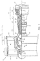
- FIG. 1 is a side cutaway illustration of a geared turbine engine 10, which is configured as a turbofan engine for an aircraft propulsion system.
- This turbine engine 10 extends along an axial centerline 12 between an upstream airflow inlet 14 and a downstream airflow exhaust 16.
- the turbine engine 10 includes a fan section 18, a compressor section 19, a combustor section 20 and a turbine section 21.
- the compressor section 19 includes a low pressure compressor (LPC) section 19A and a high pressure compressor (HPC) section 19B.
- the turbine section 21 includes a high pressure turbine (HPT) section 21A and a low pressure turbine (LPT) section 21B.
- Each of the engine sections 18, 19A, 19B, 21A and 21B includes a respective rotor 28-32.
- Each of these rotors 28-32 includes a plurality of rotor blades arranged circumferentially around and connected to one or more respective rotor disks.
- the rotor blades may be formed integral with or mechanically fastened, welded, brazed, adhered and/or otherwise attached to the respective rotor disk(s).
- the fan rotor 28 is mechanically coupled with a gear system 34, for example, through a fan shaft 36, where the gear system 34 may be configured as an epicyclic gear train or otherwise.
- the gear system 34 and the LPC rotor 29 are mechanically coupled with and driven by the LPT rotor 32 through a low speed shaft 37.
- the combination of at least the fan rotor 28, the LPC rotor 29, the LPT rotor 32, the gear system 34, the fan shaft 36 and low speed shaft 37 form a first rotating assembly 39.
- the HPC rotor 30 is mechanically coupled with and driven by the HPT rotor 31 through a high speed shaft 38.
- the combination of at least the HPC rotor 30, the HPT rotor 31 and high speed shaft 38 form a second rotating assembly 41.
- the shafts 36-38 are rotatably supported by a plurality of bearings 40; e.g., rolling element and/or thrust bearings.
- bearings 40 e.g., rolling element and/or thrust bearings.
- Each of these bearings 40 is connected to the engine housing 22 by at least one stationary structure such as, for example, an annular support strut.
- the core gas path 42 flows sequentially through the engine sections 19-21.
- the air within the core gas path 42 may be referred to as "core air”.
- the bypass gas path 44 flows through a duct between the inner case structure 24 and the outer case structure 26.
- the air within the bypass gas path 44 may be referred to as "bypass air”.
- the core air is compressed by the compressor rotors 29 and 30 and directed into a combustion chamber 46 of a combustor 48 in the combustor section 20.
- Fuel is injected into the combustion chamber 46 and mixed with the compressed core air to provide a fuel-air mixture.
- This fuel air mixture is ignited and combustion products thereof expand and flow through and sequentially cause the turbine rotors 31 and 32 to rotate.
- the rotation of the turbine rotors 31 and 32 respectively drive rotation of the compressor rotors 30 and 29 and, thus, compression of the air received from the core airflow inlet 14.
- the rotation of the turbine rotor 32 also drives rotation of the fan rotor 28, which propels bypass air through and out of the bypass gas path 44.
- the propulsion of the bypass air may account for a majority of thrust generated by the turbine engine 10, e.g., more than seventy-five percent (75%) of engine thrust.
- the turbine engine 10 of the present disclosure is not limited to the foregoing exemplary thrust ratio.
- combustor 48 may be described as being “non-operational”.
- the combustor 48 may be described as being “operational” where fuel is injected into the combustion chamber 46.
- the turbine rotors 31 and 32 are no longer caused to rotate by expanding combustion products generated by igniting a fuel-air mixture within the combustion chamber 46 as described above.
- the first and the second rotating assemblies 39 and 41 therefore may become rotationally stationary.
- the turbine engine 10 will be placed in this second mode when parked at an airport or in an airplane hangar.
- forces external to the turbine engine 10 may cause at least the first rotating assembly 39 (e.g., components 28, 29, 32, 34, 36 and 37) to rotate during the second mode.
- a headwind may enter the turbine engine 10 through the airflow inlet 14 and cause the fan rotor 28 to rotate in a first rotational direction (e.g., a counter-clockwise direction).
- a tailwind may enter the turbine engine 10 through the bypass gas path 44 and cause the fan rotor 28 to rotate in a second rotational direction (e.g., a clockwise direction), which is opposite the first direction.
- first or second direction fan rotor 28 rotation may be generally referred to as "windmilling".
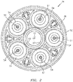
- ring gear 50 may be attached to the fan shaft 36.
- planetary gears 51 may be supported by a respective bearing 54 such as a journal bearing; however, other types of bearing configurations are contemplated by the present disclosure.
- the sin gear 52 may be attached to the low speed shaft 37.
- a typical primary lubrication system for a turbine engine utilizes a mechanical lubricant pump mounted to an accessory gearbox.
- This accessory gearbox is typically mechanically coupled to and driven by a rotating assembly which includes a HPC rotor and a HPT rotor.
- HPC and HPT rotors are typically rotationally stationary in modes where a fan rotor is windmilling for similar reasons as set forth above. Therefore, the mechanical lubricant pump of the primary lubrication system may be incapable of pumping lubricant during windmilling.
- such a lubricant pump typically utilizes suction to draw lubricant through a conduit from a lubricant reservoir to the pump.
- a lubricant pump must be driven at a relatively high rotational velocity in order to generate enough suction to draw the lubricant out of the reservoir and through the conduit.
- Driving the lubricant pump at a relatively high rotational velocity may be difficult or impossible in low wind speed conditions where the wind is utilized to power the pump.
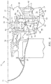
- the turbine engine 10 of the present disclosure includes a lubrication system 56 as shown in FIG. 3 .
- This lubrication system 56 may be configured as a supplemental lubrication system as described below in further detail; however, the present disclosure is not limited to such a "supplemental" configuration.
- the lubrication system 56 may be configured to lubricate the bearings 54 even where one or more of the components 28, 29, 32, 34, 36 and 37 of the first rotating assembly 39 rotate at rotational velocities near zero.
- near zero may describe a rotational velocity that is just slightly above a zero (0) rotational velocity such as, for example, a rotational velocity of less than about five revolutions per minute (RPM).
- RPM revolutions per minute
- the lubrication system 56 of FIG. 3 includes a lubricant reservoir 58, a lubricant pump 60 and a coupling assembly 62 (or device).
- the lubricant reservoir 58 may be a discrete container.
- the lubricant reservoir 58 may be formed by one or more other components of the turbine engine 10.
- the lubricant reservoir 58 is formed by one or more fluidly interconnected cavities 64-66 within other turbine engine components, which cavities may include chambers, passages, etc.
- the first cavity 64 is formed by and within a discrete portion 68 of the inner case structure 24.
- the second cavity 65 is formed by and within a hollow stator guide vane 70, which extends radially across the core gas path 42.
- the third cavity 66 is formed by and within a discrete portion 72 of a center body structure 74 of the turbine engine 10.
- the lubrication reservoir 58 of FIG. 3 is configured to contain a quantity of lubricant (see shaded region in FIG. 4 ).
- the lubricant reservoir 58 is sized such that the quantity of lubricant may fill the lubricant reservoir 58 to a lubricant level during the second mode (see FIG. 4 ).
- the lubricant reservoir 58 is also arranged in a gravitational lower region of the turbine engine 10.
- the lubricant reservoir 58 of FIG. 3 for example, is located gravitationally below the gear system 34.
- the lubricant reservoir 58 may also be located in a readably accessible region of the turbine engine 10; e.g., a region where a technician may have access while the turbine engine 10 remains attached to the aircraft and/or while the aircraft remains on the runway.
- a readably accessible region of the turbine engine 10 e.g., a region where a technician may have access while the turbine engine 10 remains attached to the aircraft and/or while the aircraft remains on the runway.
- the bottom portion of the lubricant reservoir 58 is located adjacent an area 76 which may become exposed and accessible to a technician by removal of a panel 78 of the inner case structure 24.
- the present disclosure is not limited to the foregoing exemplary lubricant reservoir 58 configuration or location.
- the lubricant pump 60 is a mechanical pump such as, but not limited to, a geared pump with constant direction gearing.
- the lubricant pump 60 is configured with the lubricant reservoir 58.
- the lubricant pump 60 of FIG. 4 is mounted to a sidewall of the inner case structure 24 which partially forms the cavity 64.
- the lubricant pump 60 is at least partially submersed within the lubricant contained in the lubricant reservoir 58.
- the lubricant pump 60 may be fully submersed within the lubricant contained in the lubricant reservoir 58 as illustrated in FIG. 5 . With these arrangements, the lubricant pump 60 may gravitationally receive the lubricant contained in the lubricant reservoir 58; e.g., gravity may force the lubricant to the pump 60.
- the lubricant pump 60 may remain primed even where the pump 60 is non-operation.
- the lubricant may remain within the lubricant pump 60 even where the pump 60 is not pumping the lubricant to the bearings 54.
- gravity may cause lubricant to flow backwards out of the pump and back to the reservoir where that pump is non-operation.
- the lubricant pump 60 of FIG. 4 does not need to generate a minimum suction force to draw the lubricant therein since the pump 60 is arranged within the lubricant.
- that pump must generate a minimum suction force to draw lubricant from the reservoir to the pump as described above.
- the lubricant pump 60 may be further configured as a line replaceable unit.
- line replaceable unit may describe a component of the turbine engine 10 which may be replaced by a technician while the airplane is parked on the runway (or within a hangar) without requiring detaching the turbine engine 10 from the airplane.
- the lubricant pump 60 of FIG. 3 is configured to be accessible to a technician through the area 76 which may become exposed and accessible by removal of the panel 78.
- the lubricant pump 60 may have alternative configurations where, for example, the pump 60 is located in the center body structure 74 and, thus, may not be a line replaceable unit.
- An outlet of the lubricant pump 60 may be fluidly coupled with a manifold structure 80 through a lubricant conduit 82, where the manifold structure 80 is configured to provide lubricant to the bearings 54.
- the lubricant pump 60 is operable to pump lubricant from the lubricant reservoir 58 to the bearings 54 for lubricating those bearings 54.
- the coupling assembly 62 is configured to mechanically couple the first rotating assembly 39 to the lubricant pump 60.
- the coupling assembly 62 of FIG. 3 is configured to mechanically couple a component of the gear system 34 to the lubricant pump 60.
- this coupling assembly 62 includes a tower shaft 84 and a bevel gear 86, which is meshed with a bevel gear 88 configured with the ring gear 52.
- the tower shaft 84 extends radially through the cavity of the guide vane 70 between a gravitational upper end and a gravitational lower end. The upper end is connected to the bevel gear 86. The lower end is mechanically coupled (directly or indirectly) to the lubricant pump 60.
- the coupling assembly 62 may include or be configured with a transmission 90.
- This transmission 90 may include one or more clutches and/or one or more sets of gearing.
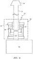
- the transmission 90 of FIG. 6 includes a set of first and second clutches 92 and 94 and associated first and second sets of gearing 96 and 98.
- the first clutch 92 e.g., a Sprag type clutch
- the first clutch 92 is configured to mechanically couple the tower shaft 84 to an input shaft 100 of the lubricant pump 60 through the first set of gearing 96, where the first rotating assembly 39 is rotating in a first rotational direction.
- the second clutch 94 (e.g., a Sprag type clutch) is configured to mechanically couple the tower shaft 84 to the input shaft 100 through the second set of gearing 98, where the first rotating assembly 39 is rotating in a second rotational direction opposite the first rotational direction.
- a Sprag type clutch e.g., a Sprag type clutch
- the second clutch 94 may be combined into a single bidirectional clutch or replaced by one or more other types of clutches.
- the transmission 90 may also or include an additional clutch 102.
- This additional clutch 102 is configured to mechanically couple the first rotating assembly 39 and, for example, tower shaft 84 in particular to the lubricant pump 60 where the first rotating assembly 39 rotates at or below a threshold rotational velocity.
- the additional clutch 102 is also configured to mechanically decouple the first rotating assembly 39 and, for example, tower shaft 84 in particular from the lubricant pump 60 where the first rotating assembly 39 rotates above the threshold rotational velocity.
- This threshold rotational velocity may be selected to correspond to a point during, for example, turbine engine 10 startup and/or low speed turbine engine 10 operation where a primary lubrication system driven by an accessory gearbox becomes operational and, thus, the lubrication system 56 is no longer needed for lubricating the bearings 54.
- the threshold rotational velocity may fall within a range between ground idle speed and about two times ground idle speed; however, the threshold rotational velocity of the present disclosure is not limited thereto.
- the additional clutch 102 may be an electrically actuated clutch. In other embodiments, the additional clutch 102 may be a mechanically actuated clutch.
- the lubrication system 56 may be configured without the transmission 90.
- the lubrication system 56 may include at least one fluid regulator 104 as shown in FIG. 5 .
- This fluid regulator 104 may be configured inline between the lubricant pump 60 and the bearing 54.
- the fluid regulator 104 for example, may be configured inline with the conduit 82.
- An example of such a fluid regulator a pressure relief valve; however, the fluid regulator 104 of the present disclosure is not limited to such a configuration.
- the lubrication system 56 may also or alternatively be configured to lubricant turbine engine components other than the bearings 54.
- the lubrication system 56 may lubricate one or more of the bearings 40 (see FIG. 1 ).
- the lubrication system 56 may lubricant one or more of the gears 50-52 (see FIG. 2 ), etc.
- the coupling assembly 62 may mechanically couple the lubricant pump 60 to another component of the first rotating assembly 39.
- the coupling assembly 62 may mechanically couple the lubricant pump 60 to one of the rotors 28, 29 or 32 or one of the shafts 36 or 37.
- the lubrication system 56 may be included in various turbine engines other than the one described above.
- the lubrication system 56 may be included in a geared turbine engine where a gear train connects one or more shafts to one or more rotors in a fan section, a compressor section and/or any other engine section.
- the lubrication system 56 may be included in a turbine engine configured without a gear train.
- the lubrication system 56 may be included in a geared or non-geared turbine engine configured with a single spool, with two spools (e.g., see FIG. 1 ), or with more than two spools.
- the turbine engine may be configured as a turbofan engine, a turbojet engine, a propfan engine, a pusher fan engine or any other type of turbine engine. The present invention therefore is not limited to any particular types or configurations of turbine engines.
Abstract
Description
- This disclosure relates generally to an aircraft propulsion system and, more particularly, to a lubrication system for a turbine engine such as a geared turbofan turbine engine.
- A turbine engine for an aircraft propulsion system typically includes a lubrication system for lubricating one or more of its components. Examples of such lubricated components include bearings, gears, seals, etc. Various types and configurations of lubrication systems are known in the art. While these lubrication systems address various problems, there is still a need in the art for an improved lubrication system for a turbine engine.
- According to an aspect of the present disclosure, a system is provided for a turbine engine. This turbine engine system includes a rotating assembly, a bearing and a lubrication system. The bearing is configured with the rotating assembly. The lubrication system is configured to lubricate the bearing. The lubrication system includes a lubricant pump and a lubricant reservoir. The lubricant pump is mechanically coupled with and driven by the rotating assembly. The lubricant pump is configured with the lubricant reservoir so as to be at least partially submersed in lubricant contained within the lubricant reservoir.
- According to another aspect of the present disclosure, another system is provided for a turbine engine. This turbine engine system includes a rotating assembly, a bearing and a lubrication system. The bearing is configured with the rotating assembly. The lubrication system is configured to lubricate the bearing as the rotating assembly rotates at less than about five revolutions per minute (~5rpm). The lubrication system includes a lubricant pump mechanically coupled with and driven by the rotating assembly.
- According to another aspect of the present disclosure, a turbine engine is provided for an aircraft propulsion system. This turbine engine includes a fan rotor, a turbine rotor, a gear system and a lubrication system. The gear system mechanically couples the fan rotor with the turbine rotor. The gear system includes a bearing. The lubrication system is configured to lubricate the bearing. The lubrication system includes a lubricant pump and a lubricant reservoir. The lubricant pump is mechanically coupled with and driven by the gear system. The lubricant pump is configured with the lubricant reservoir so as to gravitationally receive lubricant contained within the lubricant reservoir.
- The lubricant pump may be configured with the lubricant reservoir so as to be substantially completely submersed in lubricant contained within the lubricant reservoir.
- The lubrication system may include a lubricant reservoir. The lubricant pump may be configured with the lubricant reservoir so as to be at least partially submersed in lubricant contained within the lubricant reservoir.
- The lubrication system may be configured to lubricate the bearing as the fan rotor rotates at less than about five revolutions per minute (∼5rpm).
- The rotating assembly may include a fan rotor, a compressor rotor and a turbine rotor.
- The rotating assembly may also include a gear system mechanically coupled between the fan rotor and the compressor rotor and/or the turbine rotor. The bearing may be configured with the gear system.
- The bearing may be configured as or include a journal bearing.
- The fan rotor may be operable to windmill. The lubrication system may be configured to lubricate the bearing during the windmilling.
- The lubrication system may be configured to lubricate the bearing as the rotating assembly rotates in a first rotational direction. The lubrication system may also or alternatively be configured to lubricate the bearing as the rotating assembly rotates in a second rotational direction.
- The lubrication system may be operable to lubricate the bearing where the rotating assembly rotates starting at less than five revolutions per minute (∼5rpm).
- The lubrication system may be operable to lubricate the bearing where the rotating assembly rotates at a near zero rotational velocity.
- The lubrication system may include a clutch configured to mechanically couple the lubricant pump to the rotating assembly where the rotating assembly rotates at or below a threshold rotational velocity. The clutch may also or alternatively be configured to mechanically decouple the lubricant pump from the rotating assembly where the rotating assembly rotates above the threshold rotational velocity.
- The clutch may be a mechanically actuated clutch. Alternatively, the clutch may be an electrically actuated clutch.
- The clutch may be configured for mounting with the turbine engine as a line replaceable unit. In addition or alternatively, the lubricant pump may be configured for mounting with the turbine engine as a line replaceable unit.
- The lubricant pump may be configured for mounting with the turbine engine as a line replaceable unit.
- The lubrication system may include a lubricant flow regulator arranged inline between the lubricant pump and the bearing.
- A combustor and a second lubrication system may be included. The second lubrication system may be configured to lubricate the bearing during at least a mode of operation where the combustor is operational. In this mode, the lubrication system may be non-operation and, therefore, not provide lubricate to the bearing. The lubrication system may be configured to lubricate the bearing during at least another mode of operation where the combustor is non-operational. In this other mode, the second lubrication system may be non-operation and, therefore, not provide lubricate to the bearing.
- A guide vane and a tower shaft may be included. The tower shaft may extend radially through the guide vane. A gravitational upper end of the tower shaft may be mechanically coupled with the rotating assembly. A gravitational lower end of the tower shaft may be mechanically coupled with the lubricant pump.
- The foregoing features and the operation of the invention will become more apparent in light of the following description and the accompanying drawings.
-
-
FIG. 1 is a side cutaway illustration of a geared turbine engine. -
FIG. 2 is a cross-sectional illustration of a gear system for the turbine engine. -
FIG. 3 is a schematic diagram of a lubrication system configured with the turbine engine. -
FIG. 4 is another schematic diagram of the lubrication system configured with the turbine engine, where a lubricant reservoir for the lubrication system is filled with lubricant. -
FIG. 5 is a schematic diagram of another lubrication system configured with the turbine engine. -
FIG. 6 is a block diagram of a coupling system connected with a lubricant pump for the lubrication system. -
FIG. 7 is a block diagram of another coupling system connected with the lubricant pump for the lubrication system. -
FIG. 1 is a side cutaway illustration of a gearedturbine engine 10, which is configured as a turbofan engine for an aircraft propulsion system. Thisturbine engine 10 extends along anaxial centerline 12 between anupstream airflow inlet 14 and adownstream airflow exhaust 16. - The
turbine engine 10 includes afan section 18, acompressor section 19, acombustor section 20 and aturbine section 21. Thecompressor section 19 includes a low pressure compressor (LPC)section 19A and a high pressure compressor (HPC)section 19B. Theturbine section 21 includes a high pressure turbine (HPT)section 21A and a low pressure turbine (LPT)section 21B. - Each of the
engine sections - The
fan rotor 28 is mechanically coupled with agear system 34, for example, through afan shaft 36, where thegear system 34 may be configured as an epicyclic gear train or otherwise. Thegear system 34 and theLPC rotor 29 are mechanically coupled with and driven by theLPT rotor 32 through alow speed shaft 37. The combination of at least thefan rotor 28, theLPC rotor 29, theLPT rotor 32, thegear system 34, thefan shaft 36 andlow speed shaft 37 form a firstrotating assembly 39. TheHPC rotor 30 is mechanically coupled with and driven by theHPT rotor 31 through ahigh speed shaft 38. The combination of at least theHPC rotor 30, theHPT rotor 31 andhigh speed shaft 38 form a secondrotating assembly 41. The shafts 36-38 are rotatably supported by a plurality ofbearings 40; e.g., rolling element and/or thrust bearings. Each of thesebearings 40 is connected to theengine housing 22 by at least one stationary structure such as, for example, an annular support strut. - During a first mode of
turbine engine 10 operation, air enters theturbine engine 10 through theairflow inlet 14. This air is directed through thefan section 18 and into acore gas path 42 and abypass gas path 44. Thecore gas path 42 flows sequentially through the engine sections 19-21. The air within thecore gas path 42 may be referred to as "core air". Thebypass gas path 44 flows through a duct between theinner case structure 24 and theouter case structure 26. The air within thebypass gas path 44 may be referred to as "bypass air". - The core air is compressed by the
compressor rotors combustion chamber 46 of acombustor 48 in thecombustor section 20. Fuel is injected into thecombustion chamber 46 and mixed with the compressed core air to provide a fuel-air mixture. This fuel air mixture is ignited and combustion products thereof expand and flow through and sequentially cause theturbine rotors turbine rotors compressor rotors core airflow inlet 14. The rotation of theturbine rotor 32 also drives rotation of thefan rotor 28, which propels bypass air through and out of thebypass gas path 44. The propulsion of the bypass air may account for a majority of thrust generated by theturbine engine 10, e.g., more than seventy-five percent (75%) of engine thrust. Theturbine engine 10 of the present disclosure, however, is not limited to the foregoing exemplary thrust ratio. - During a second mode of
turbine engine 10 operation, fuel may no longer be injected into and ignited within thecombustion chamber 46. Thus, during this second mode, thecombustor 48 may be described as being "non-operational". In contrast, in the first mode described above, thecombustor 48 may be described as being "operational" where fuel is injected into thecombustion chamber 46. - Due to aforementioned fuel cutoff, the
turbine rotors combustion chamber 46 as described above. The first and the secondrotating assemblies turbine engine 10 will be placed in this second mode when parked at an airport or in an airplane hangar. - Under certain conditions, forces external to the
turbine engine 10 may cause at least the first rotating assembly 39 (e.g.,components turbine engine 10 through theairflow inlet 14 and cause thefan rotor 28 to rotate in a first rotational direction (e.g., a counter-clockwise direction). In another example, a tailwind may enter theturbine engine 10 through thebypass gas path 44 and cause thefan rotor 28 to rotate in a second rotational direction (e.g., a clockwise direction), which is opposite the first direction. Such first or seconddirection fan rotor 28 rotation may be generally referred to as "windmilling". - During windmilling, rotation of the
fan rotor 28 causes corresponding rotation of theLPC rotor 29 and theLPT rotor 32 and, thus, one or more internal components of thegear system 34. Referring toFIG. 2 , examples of such internal components include, but are not limited to aring gear 50,planetary gears 51 and asun gear 52. Thering gear 50 may be attached to thefan shaft 36. Each of theplanetary gears 51 may be supported by arespective bearing 54 such as a journal bearing; however, other types of bearing configurations are contemplated by the present disclosure. Thesin gear 52 may be attached to thelow speed shaft 37. - It may be desirable to lubricate one or more turbine engine components, such as one or more of the
bearings 54, during windmilling in order to reduce or prevent wear thereto. However, a typical primary lubrication system for a turbine engine utilizes a mechanical lubricant pump mounted to an accessory gearbox. This accessory gearbox is typically mechanically coupled to and driven by a rotating assembly which includes a HPC rotor and a HPT rotor. These HPC and HPT rotors are typically rotationally stationary in modes where a fan rotor is windmilling for similar reasons as set forth above. Therefore, the mechanical lubricant pump of the primary lubrication system may be incapable of pumping lubricant during windmilling. Furthermore, even where the mechanical lubricant pump is driven by the rotating assembly during windmilling or another means, such a lubricant pump typically utilizes suction to draw lubricant through a conduit from a lubricant reservoir to the pump. Thus, such a lubricant pump must be driven at a relatively high rotational velocity in order to generate enough suction to draw the lubricant out of the reservoir and through the conduit. Driving the lubricant pump at a relatively high rotational velocity may be difficult or impossible in low wind speed conditions where the wind is utilized to power the pump. - In order to lubricate one or more of the
bearings 54 during windmilling and/or other conditions / modes, theturbine engine 10 of the present disclosure includes alubrication system 56 as shown inFIG. 3 . Thislubrication system 56 may be configured as a supplemental lubrication system as described below in further detail; however, the present disclosure is not limited to such a "supplemental" configuration. - The
lubrication system 56 may be configured to lubricate thebearings 54 even where one or more of thecomponents rotating assembly 39 rotate at rotational velocities near zero. Herein, the term "near zero" may describe a rotational velocity that is just slightly above a zero (0) rotational velocity such as, for example, a rotational velocity of less than about five revolutions per minute (RPM). The present disclosure, of course, is not limited to such a near zero operational configuration. - The
lubrication system 56 ofFIG. 3 includes alubricant reservoir 58, alubricant pump 60 and a coupling assembly 62 (or device). Thelubricant reservoir 58 may be a discrete container. In addition or alternatively, thelubricant reservoir 58 may be formed by one or more other components of theturbine engine 10. For example, as illustrated inFIGS. 3 and4 , thelubricant reservoir 58 is formed by one or more fluidly interconnected cavities 64-66 within other turbine engine components, which cavities may include chambers, passages, etc. Thefirst cavity 64 is formed by and within adiscrete portion 68 of theinner case structure 24. Thesecond cavity 65 is formed by and within a hollowstator guide vane 70, which extends radially across thecore gas path 42. Thethird cavity 66 is formed by and within adiscrete portion 72 of acenter body structure 74 of theturbine engine 10. - The
lubrication reservoir 58 ofFIG. 3 is configured to contain a quantity of lubricant (see shaded region inFIG. 4 ). Thelubricant reservoir 58 is sized such that the quantity of lubricant may fill thelubricant reservoir 58 to a lubricant level during the second mode (seeFIG. 4 ). Thelubricant reservoir 58 is also arranged in a gravitational lower region of theturbine engine 10. Thelubricant reservoir 58 ofFIG. 3 , for example, is located gravitationally below thegear system 34. Thelubricant reservoir 58 may also be located in a readably accessible region of theturbine engine 10; e.g., a region where a technician may have access while theturbine engine 10 remains attached to the aircraft and/or while the aircraft remains on the runway. InFIG. 3 , for example, the bottom portion of thelubricant reservoir 58 is located adjacent anarea 76 which may become exposed and accessible to a technician by removal of apanel 78 of theinner case structure 24. Of course, the present disclosure is not limited to the foregoingexemplary lubricant reservoir 58 configuration or location. - The
lubricant pump 60 is a mechanical pump such as, but not limited to, a geared pump with constant direction gearing. Thelubricant pump 60 is configured with thelubricant reservoir 58. In particular, thelubricant pump 60 ofFIG. 4 is mounted to a sidewall of theinner case structure 24 which partially forms thecavity 64. In this location, thelubricant pump 60 is at least partially submersed within the lubricant contained in thelubricant reservoir 58. Of course, in other embodiments, thelubricant pump 60 may be fully submersed within the lubricant contained in thelubricant reservoir 58 as illustrated inFIG. 5 . With these arrangements, thelubricant pump 60 may gravitationally receive the lubricant contained in thelubricant reservoir 58; e.g., gravity may force the lubricant to thepump 60. - By maintaining the
lubricant pump 60 at least partially submersed within the lubricant, thelubricant pump 60 may remain primed even where thepump 60 is non-operation. For example, the lubricant may remain within thelubricant pump 60 even where thepump 60 is not pumping the lubricant to thebearings 54. In contrast, where a pump is located outside of a reservoir, gravity may cause lubricant to flow backwards out of the pump and back to the reservoir where that pump is non-operation. Furthermore, thelubricant pump 60 ofFIG. 4 does not need to generate a minimum suction force to draw the lubricant therein since thepump 60 is arranged within the lubricant. In contrast, where a pump is located outside of a reservoir or above lubricant within the reservoir, that pump must generate a minimum suction force to draw lubricant from the reservoir to the pump as described above. - Referring now to
FIG. 3 , thelubricant pump 60 may be further configured as a line replaceable unit. Herein, the term "line replaceable unit" may describe a component of theturbine engine 10 which may be replaced by a technician while the airplane is parked on the runway (or within a hangar) without requiring detaching theturbine engine 10 from the airplane. For example, thelubricant pump 60 ofFIG. 3 is configured to be accessible to a technician through thearea 76 which may become exposed and accessible by removal of thepanel 78. Of course, in other embodiments, thelubricant pump 60 may have alternative configurations where, for example, thepump 60 is located in thecenter body structure 74 and, thus, may not be a line replaceable unit. - An outlet of the
lubricant pump 60 may be fluidly coupled with amanifold structure 80 through alubricant conduit 82, where themanifold structure 80 is configured to provide lubricant to thebearings 54. In this manner, thelubricant pump 60 is operable to pump lubricant from thelubricant reservoir 58 to thebearings 54 for lubricating thosebearings 54. - The
coupling assembly 62 is configured to mechanically couple the firstrotating assembly 39 to thelubricant pump 60. Thecoupling assembly 62 ofFIG. 3 , for example, is configured to mechanically couple a component of thegear system 34 to thelubricant pump 60. In particular, thiscoupling assembly 62 includes atower shaft 84 and abevel gear 86, which is meshed with abevel gear 88 configured with thering gear 52. Thetower shaft 84 extends radially through the cavity of theguide vane 70 between a gravitational upper end and a gravitational lower end. The upper end is connected to thebevel gear 86. The lower end is mechanically coupled (directly or indirectly) to thelubricant pump 60. - Referring to
FIG. 6 , to facilitate operation of thelubricant pump 60 where the firstrotating assembly 39 may rotate in both first and second directions, thecoupling assembly 62 may include or be configured with atransmission 90. Thistransmission 90 may include one or more clutches and/or one or more sets of gearing. For example, thetransmission 90 ofFIG. 6 includes a set of first andsecond clutches tower shaft 84 to aninput shaft 100 of thelubricant pump 60 through the first set of gearing 96, where the firstrotating assembly 39 is rotating in a first rotational direction. The second clutch 94 (e.g., a Sprag type clutch) is configured to mechanically couple thetower shaft 84 to theinput shaft 100 through the second set of gearing 98, where the firstrotating assembly 39 is rotating in a second rotational direction opposite the first rotational direction. Of course, in other embodiments, one or more of theclutches - In some embodiments, referring to
FIG. 7 , thetransmission 90 may also or include anadditional clutch 102. This additional clutch 102 is configured to mechanically couple the firstrotating assembly 39 and, for example,tower shaft 84 in particular to thelubricant pump 60 where the firstrotating assembly 39 rotates at or below a threshold rotational velocity. Theadditional clutch 102 is also configured to mechanically decouple the firstrotating assembly 39 and, for example,tower shaft 84 in particular from thelubricant pump 60 where the firstrotating assembly 39 rotates above the threshold rotational velocity. This threshold rotational velocity may be selected to correspond to a point during, for example,turbine engine 10 startup and/or lowspeed turbine engine 10 operation where a primary lubrication system driven by an accessory gearbox becomes operational and, thus, thelubrication system 56 is no longer needed for lubricating thebearings 54. For example, the threshold rotational velocity may fall within a range between ground idle speed and about two times ground idle speed; however, the threshold rotational velocity of the present disclosure is not limited thereto. - In some embodiments, the
additional clutch 102 may be an electrically actuated clutch. In other embodiments, theadditional clutch 102 may be a mechanically actuated clutch. - In some embodiments, the
lubrication system 56 may be configured without thetransmission 90. - In some embodiments, the
lubrication system 56 may include at least onefluid regulator 104 as shown inFIG. 5 . Thisfluid regulator 104 may be configured inline between thelubricant pump 60 and thebearing 54. Thefluid regulator 104, for example, may be configured inline with theconduit 82. An example of such a fluid regulator a pressure relief valve; however, thefluid regulator 104 of the present disclosure is not limited to such a configuration. - In some embodiments, the
lubrication system 56 may also or alternatively be configured to lubricant turbine engine components other than thebearings 54. For example, thelubrication system 56 may lubricate one or more of the bearings 40 (seeFIG. 1 ). In another example, thelubrication system 56 may lubricant one or more of the gears 50-52 (seeFIG. 2 ), etc. - In some embodiments, the
coupling assembly 62 may mechanically couple thelubricant pump 60 to another component of the firstrotating assembly 39. For example, thecoupling assembly 62 may mechanically couple thelubricant pump 60 to one of therotors shafts - The
lubrication system 56 may be included in various turbine engines other than the one described above. Thelubrication system 56, for example, may be included in a geared turbine engine where a gear train connects one or more shafts to one or more rotors in a fan section, a compressor section and/or any other engine section. Alternatively, thelubrication system 56 may be included in a turbine engine configured without a gear train. Thelubrication system 56 may be included in a geared or non-geared turbine engine configured with a single spool, with two spools (e.g., seeFIG. 1 ), or with more than two spools. The turbine engine may be configured as a turbofan engine, a turbojet engine, a propfan engine, a pusher fan engine or any other type of turbine engine. The present invention therefore is not limited to any particular types or configurations of turbine engines. - While various embodiments of the present invention have been disclosed, it will be apparent to those of ordinary skill in the art that many more embodiments and implementations are possible within the scope of the invention. For example, the present invention as described herein includes several aspects and embodiments that include particular features. Although these features may be described individually, it is within the scope of the present invention that some or all of these features may be combined with any one of the aspects and remain within the scope of the invention. Accordingly, the present invention is not to be restricted except in light of the attached claims and their equivalents.
Claims (13)
- A system for a turbine engine, comprising:a rotating assembly (39);a bearing (54) configured with the rotating assembly (39); anda lubrication system (56) configured to lubricate the bearing (54) as the rotating assembly (39) rotates at less than about five revolutions per minute;wherein the lubrication system (56) includes a lubricant pump (60) mechanically coupled with and driven by the rotating assembly (39).
- The system of claim 1, wherein the rotating assembly (39) includes a fan rotor (28), a compressor rotor (29, 30) and a turbine rotor (31, 32).
- The system of claim 2, wherein the rotating assembly (39) further includes a gear system (34) mechanically coupled between the fan rotor (28) and the turbine rotor (29, 30), and the bearing (54) is configured with the gear system (34);
wherein optionally the bearing comprises a journal bearing. - The system of claim 2 or 3, wherein the fan rotor (28) is operable to windmill, and the lubrication system (56) is configured to lubricate the bearing (54) during the windmilling.
- The system of any preceding claim, wherein the lubrication system (56) is configured to lubricate the bearing (54) as the rotating assembly (39) rotates in a first rotational direction and a second rotational direction.
- The system of any preceding claim, wherein the lubrication system (56) further includes a clutch (92) configured to:mechanically couple the lubricant pump (60) to the rotating assembly (39) where the rotating assembly (39) rotates at or below a threshold rotational velocity; andmechanically decouple the lubricant pump (60) from the rotating assembly (39) where the rotating assembly (39) rotates above the threshold rotational velocity.
- The system of claim 6, wherein the clutch (92) is a mechanically or electrically actuated clutch.
- The system of claim 6 or 7, wherein the clutch (92) is configured for mounting with the turbine engine as a line replaceable unit.
- The system of any preceding claim, wherein the lubricant pump (60) is configured for mounting with the turbine engine as a line replaceable unit.
- The system of any preceding claim, wherein the lubrication system (56) further includes a lubricant flow regulator (104) arranged inline between the lubricant pump (60) and the bearing (54).
- The system of any preceding claim, further comprising:a combustor (48); anda second lubrication system configured to lubricate the bearing (54) during at least a mode of operation where the combustor (48) is operational;wherein the lubrication system (56) is configured to lubricate the bearing (54) during at least another mode of operation where the combustor (48) is non-operational.
- The system of any preceding claim, further comprising:a guide vane (70); anda tower shaft (84) extending radially through the guide vane (70);wherein a gravitational upper end of the tower shaft (84) is mechanically coupled with the rotating assembly (39), and a gravitational lower end of the tower shaft (84) is mechanically coupled with the lubricant pump (60).
- The system of any preceding claim, wherein the lubrication system (56) further includes a lubricant reservoir (58), and the lubricant pump (60) is configured with the lubricant reservoir (58) so as to be at least partially submersed in lubricant contained within the lubricant reservoir (58).
Applications Claiming Priority (2)
| Application Number | Priority Date | Filing Date | Title |
|---|---|---|---|
| US14/949,273 US10570824B2 (en) | 2015-11-23 | 2015-11-23 | Near zero velocity lubrication system for a turbine engine |
| EP16199918.0A EP3171055B1 (en) | 2015-11-23 | 2016-11-22 | Near zero velocity lubrication system for a turbine engine |
Related Parent Applications (1)
| Application Number | Title | Priority Date | Filing Date |
|---|---|---|---|
| EP16199918.0A Division EP3171055B1 (en) | 2015-11-23 | 2016-11-22 | Near zero velocity lubrication system for a turbine engine |
Publications (2)
| Publication Number | Publication Date |
|---|---|
| EP3865735A1 true EP3865735A1 (en) | 2021-08-18 |
| EP3865735B1 EP3865735B1 (en) | 2023-12-27 |
Family
ID=57389285
Family Applications (2)
| Application Number | Title | Priority Date | Filing Date |
|---|---|---|---|
| EP21159742.2A Active EP3865735B1 (en) | 2015-11-23 | 2016-11-22 | Near zero velocity lubrication system for a turbine engine |
| EP16199918.0A Active EP3171055B1 (en) | 2015-11-23 | 2016-11-22 | Near zero velocity lubrication system for a turbine engine |
Family Applications After (1)
| Application Number | Title | Priority Date | Filing Date |
|---|---|---|---|
| EP16199918.0A Active EP3171055B1 (en) | 2015-11-23 | 2016-11-22 | Near zero velocity lubrication system for a turbine engine |
Country Status (2)
| Country | Link |
|---|---|
| US (1) | US10570824B2 (en) |
| EP (2) | EP3865735B1 (en) |
Families Citing this family (9)
| Publication number | Priority date | Publication date | Assignee | Title |
|---|---|---|---|---|
| US10539053B2 (en) * | 2017-07-06 | 2020-01-21 | General Electric Company | Engine transportation apparatus |
| DE102017128384A1 (en) * | 2017-11-30 | 2019-06-06 | Rolls-Royce Corporation | Jet engine |
| US10982678B2 (en) | 2018-05-21 | 2021-04-20 | Raytheon Technologies Corporation | Epicyclic drive for gas turbine engine lubricant pump |
| US11441450B2 (en) * | 2018-06-06 | 2022-09-13 | Raytheon Technologies Corporation | Dual direction windmill pump for geared turbofan engines |
| FR3092367B1 (en) * | 2019-02-05 | 2021-02-12 | Safran Aircraft Engines | AIRCRAFT TURBOMACHINE |
| WO2020180366A1 (en) * | 2019-03-01 | 2020-09-10 | United Technologies Advanced Projects Inc. | Circulating coolant fluid in hybrid electrical propulsion systems |
| GB201905207D0 (en) | 2019-04-12 | 2019-05-29 | Rolls Royce Plc | Gas turbine engine generator oil pump |
| FR3096742B1 (en) * | 2019-05-31 | 2021-05-14 | Safran Aircraft Engines | Aircraft turbomachine comprising a disengageable pump for lubricating a fan reducer. |
| FR3109963B1 (en) * | 2020-05-06 | 2022-10-07 | Safran Aircraft Engines | LUBRICATION MODULE FOR A TURBOMACHINE BLOWER GEARBOX IN THE FAN AUTOROTATION PHASE |
Citations (3)
| Publication number | Priority date | Publication date | Assignee | Title |
|---|---|---|---|---|
| US20060260323A1 (en) * | 2005-05-19 | 2006-11-23 | Djamal Moulebhar | Aircraft with disengageable engine and auxiliary power unit components |
| EP2584174A2 (en) * | 2011-10-21 | 2013-04-24 | United Technologies Corporation | Windmill operation of a gas turbine engine |
| US20130319798A1 (en) * | 2012-05-31 | 2013-12-05 | William G. Sheridan | Auxiliary oil system for negative gravity event |
Family Cites Families (27)
| Publication number | Priority date | Publication date | Assignee | Title |
|---|---|---|---|---|
| GB1322405A (en) * | 1970-10-02 | 1973-07-04 | Secr Defence | Oil systems for gas turbine engines |
| DE3714990A1 (en) | 1987-05-06 | 1988-12-01 | Mtu Muenchen Gmbh | PROPFAN TURBO ENGINE |
| US4922119A (en) * | 1988-11-29 | 1990-05-01 | Sundstrand Corporation | Integrated starting system |
| DE19645005A1 (en) | 1995-11-01 | 1997-05-07 | Samsung Electronics Co Ltd | Determining colour temperature colour display arrangement e.g. CRT, LCD |
| US7377098B2 (en) * | 2004-08-26 | 2008-05-27 | United Technologies Corporation | Gas turbine engine frame with an integral fluid reservoir and air/fluid heat exchanger |
| US7530430B2 (en) | 2004-11-04 | 2009-05-12 | Pratt & Whitney Canada Corp. | Pressure lubrication for inverted flight |
| US8312728B2 (en) * | 2007-06-28 | 2012-11-20 | United Technologies Corporation | Generator with separate oil system for improved nacelle performance |
| JP4990122B2 (en) | 2007-12-28 | 2012-08-01 | 本田技研工業株式会社 | Engine oil pump drive |
| US8192143B2 (en) * | 2008-05-21 | 2012-06-05 | United Technologies Corporation | Gearbox assembly |
| US8627667B2 (en) * | 2008-12-29 | 2014-01-14 | Roll-Royce Corporation | Gas turbine engine duct having a coupled fluid volume |
| US8230974B2 (en) | 2009-05-22 | 2012-07-31 | United Technologies Corporation | Windmill and zero gravity lubrication system for a gas turbine engine |
| US8381878B2 (en) | 2009-11-12 | 2013-02-26 | United Technologies Corporation | Oil capture and bypass system |
| US8312969B2 (en) * | 2010-06-29 | 2012-11-20 | Pratt & Whitney Canada Corp. | Lubrication system for aircraft engine |
| US8893469B2 (en) | 2011-06-22 | 2014-11-25 | United Technologies Corporation | Oil bypass channel deaerator for a geared turbofan engine |
| US8966876B2 (en) * | 2011-10-21 | 2015-03-03 | United Technologies Corporation | Controllable speed windmill operation of a gas turbine engine through low spool power extraction |
| US9970352B2 (en) * | 2012-01-27 | 2018-05-15 | United Technologies Corporation | Turbomachine fan clutch |
| US9194294B2 (en) * | 2012-05-07 | 2015-11-24 | United Technologies Corporation | Gas turbine engine oil tank |
| US9945252B2 (en) * | 2012-07-05 | 2018-04-17 | United Technologies Corporation | Gas turbine engine oil tank with integrated packaging configuration |
| US9404381B2 (en) | 2012-09-04 | 2016-08-02 | United Technologies Corporation | Turbine engine transmission gutter |
| US10208624B2 (en) | 2013-02-26 | 2019-02-19 | United Technologies Corporation | Lubrication of journal bearing during clockwise and counter-clockwise rotation |
| GB2511315B (en) | 2013-02-27 | 2016-08-10 | Ford Global Tech Llc | Oil pump drive |
| US8702373B1 (en) | 2013-07-15 | 2014-04-22 | United Technologies Corporation | Lubrication of journal bearing during clockwise and counter-clockwise rotation |
| US9739173B2 (en) | 2013-10-01 | 2017-08-22 | United Technologies Corporation | Gas turbine lubrication systems |
| US10196926B2 (en) * | 2014-04-11 | 2019-02-05 | United Technologies Corporation | Lubricating a rotating component during forward and/or reverse rotation |
| DE102014117960A1 (en) * | 2014-12-05 | 2016-06-09 | Rolls-Royce Deutschland Ltd & Co Kg | Aircraft with an apparatus for separating oil and a device for increasing a pressure |
| US9897010B2 (en) * | 2015-03-30 | 2018-02-20 | Honeywell International Inc. | Air turbine starter systems including gearbox-integrated clutch modules and gas turbine engines employing the same |
| US10634053B2 (en) * | 2015-12-21 | 2020-04-28 | United Technologies Corporation | Electric windmill pump for gearbox durability |
-
2015
- 2015-11-23 US US14/949,273 patent/US10570824B2/en active Active
-
2016
- 2016-11-22 EP EP21159742.2A patent/EP3865735B1/en active Active
- 2016-11-22 EP EP16199918.0A patent/EP3171055B1/en active Active
Patent Citations (3)
| Publication number | Priority date | Publication date | Assignee | Title |
|---|---|---|---|---|
| US20060260323A1 (en) * | 2005-05-19 | 2006-11-23 | Djamal Moulebhar | Aircraft with disengageable engine and auxiliary power unit components |
| EP2584174A2 (en) * | 2011-10-21 | 2013-04-24 | United Technologies Corporation | Windmill operation of a gas turbine engine |
| US20130319798A1 (en) * | 2012-05-31 | 2013-12-05 | William G. Sheridan | Auxiliary oil system for negative gravity event |
Also Published As
| Publication number | Publication date |
|---|---|
| EP3865735B1 (en) | 2023-12-27 |
| US10570824B2 (en) | 2020-02-25 |
| US20170145920A1 (en) | 2017-05-25 |
| EP3171055A1 (en) | 2017-05-24 |
| EP3171055B1 (en) | 2021-03-31 |
Similar Documents
| Publication | Publication Date | Title |
|---|---|---|
| EP3171055B1 (en) | Near zero velocity lubrication system for a turbine engine | |
| CN110185775B (en) | Passive lubrication system for gas turbine engine gearbox during wind turns | |
| EP3282093B1 (en) | Geared turbofan with low spool power extraction | |
| EP2224120B1 (en) | Auxiliary lubricating pump for turbofan drive gear system | |
| US10196926B2 (en) | Lubricating a rotating component during forward and/or reverse rotation | |
| US7493753B2 (en) | Gas turbine engine assembly and methods of assembling same | |
| US9062611B2 (en) | Split accessory drive system | |
| EP3449101B1 (en) | Integral offset oil tank for inline accessory gearbox | |
| US10197150B2 (en) | Gear baffle configured with lubricant outlet passage | |
| EP3047126B1 (en) | Dual direction windmill pump for geared turbofan engine | |
| EP3636899B1 (en) | Coupling shaft for gas turbine fan drive gear system | |
| RU2686248C2 (en) | Front part of aircraft double-flow gas turbine engine and aircraft double-flow gas turbine engine | |
| EP3597885B1 (en) | Gear train architecture for a multi-spool gas turbine engine | |
| JP2007534873A (en) | Gas turbine engine with a single oil cavity or gas turbine engine with inner and outer concentric shafts | |
| EP2959129B1 (en) | Auxiliary lubricant supply pump stage integral with main lubricant pump stage | |
| US9260980B2 (en) | Rotating fluid pumping system | |
| EP3543483A1 (en) | Windmill lubrication gear train for lubricant system in a geared gas turbine engine | |
| EP2900979A1 (en) | Geared turbofan with fan and core mounted accessory gearboxes | |
| CA2970389A1 (en) | Gear train architecture for a multi-spool gas turbine engine | |
| EP3260668A1 (en) | Lubrication system with multiple lubrication circuits | |
| EP2946082B1 (en) | Oil pump transfer plate |
Legal Events
| Date | Code | Title | Description |
|---|---|---|---|
| PUAI | Public reference made under article 153(3) epc to a published international application that has entered the european phase |
Free format text: ORIGINAL CODE: 0009012 |
|
| STAA | Information on the status of an ep patent application or granted ep patent |
Free format text: STATUS: THE APPLICATION HAS BEEN PUBLISHED |
|
| AC | Divisional application: reference to earlier application |
Ref document number: 3171055 Country of ref document: EP Kind code of ref document: P |
|
| AK | Designated contracting states |
Kind code of ref document: A1 Designated state(s): AL AT BE BG CH CY CZ DE DK EE ES FI FR GB GR HR HU IE IS IT LI LT LU LV MC MK MT NL NO PL PT RO RS SE SI SK SM TR |
|
| STAA | Information on the status of an ep patent application or granted ep patent |
Free format text: STATUS: REQUEST FOR EXAMINATION WAS MADE |
|
| 17P | Request for examination filed |
Effective date: 20220218 |
|
| RBV | Designated contracting states (corrected) |
Designated state(s): AL AT BE BG CH CY CZ DE DK EE ES FI FR GB GR HR HU IE IS IT LI LT LU LV MC MK MT NL NO PL PT RO RS SE SI SK SM TR |
|
| RIC1 | Information provided on ipc code assigned before grant |
Ipc: F01M 11/00 20060101ALN20230503BHEP Ipc: F01M 1/02 20060101ALN20230503BHEP Ipc: F02C 7/32 20060101ALI20230503BHEP Ipc: F02C 3/107 20060101ALI20230503BHEP Ipc: F16H 57/04 20100101AFI20230503BHEP |
|
| GRAP | Despatch of communication of intention to grant a patent |
Free format text: ORIGINAL CODE: EPIDOSNIGR1 |
|
| STAA | Information on the status of an ep patent application or granted ep patent |
Free format text: STATUS: GRANT OF PATENT IS INTENDED |
|
| RIC1 | Information provided on ipc code assigned before grant |
Ipc: F01M 11/00 20060101ALN20230512BHEP Ipc: F01M 1/02 20060101ALN20230512BHEP Ipc: F02C 7/32 20060101ALI20230512BHEP Ipc: F02C 3/107 20060101ALI20230512BHEP Ipc: F16H 57/04 20100101AFI20230512BHEP |
|
| RIC1 | Information provided on ipc code assigned before grant |
Ipc: F01M 11/00 20060101ALN20230601BHEP Ipc: F01M 1/02 20060101ALN20230601BHEP Ipc: F02C 7/32 20060101ALI20230601BHEP Ipc: F02C 3/107 20060101ALI20230601BHEP Ipc: F16H 57/04 20100101AFI20230601BHEP |
|
| INTG | Intention to grant announced |
Effective date: 20230620 |
|
| GRAS | Grant fee paid |
Free format text: ORIGINAL CODE: EPIDOSNIGR3 |
|
| RAP3 | Party data changed (applicant data changed or rights of an application transferred) |
Owner name: RTX CORPORATION |
|
| GRAA | (expected) grant |
Free format text: ORIGINAL CODE: 0009210 |
|
| STAA | Information on the status of an ep patent application or granted ep patent |
Free format text: STATUS: THE PATENT HAS BEEN GRANTED |
|
| AC | Divisional application: reference to earlier application |
Ref document number: 3171055 Country of ref document: EP Kind code of ref document: P |
|
| AK | Designated contracting states |
Kind code of ref document: B1 Designated state(s): AL AT BE BG CH CY CZ DE DK EE ES FI FR GB GR HR HU IE IS IT LI LT LU LV MC MK MT NL NO PL PT RO RS SE SI SK SM TR |
|
| REG | Reference to a national code |
Ref country code: GB Ref legal event code: FG4D |
|
| REG | Reference to a national code |
Ref country code: CH Ref legal event code: EP |
|
| REG | Reference to a national code |
Ref country code: DE Ref legal event code: R096 Ref document number: 602016085091 Country of ref document: DE |
|
| REG | Reference to a national code |
Ref country code: IE Ref legal event code: FG4D |
|
| PG25 | Lapsed in a contracting state [announced via postgrant information from national office to epo] |
Ref country code: GR Free format text: LAPSE BECAUSE OF FAILURE TO SUBMIT A TRANSLATION OF THE DESCRIPTION OR TO PAY THE FEE WITHIN THE PRESCRIBED TIME-LIMIT Effective date: 20240328 |
|
| REG | Reference to a national code |
Ref country code: LT Ref legal event code: MG9D |
|
| PG25 | Lapsed in a contracting state [announced via postgrant information from national office to epo] |
Ref country code: LT Free format text: LAPSE BECAUSE OF FAILURE TO SUBMIT A TRANSLATION OF THE DESCRIPTION OR TO PAY THE FEE WITHIN THE PRESCRIBED TIME-LIMIT Effective date: 20231227 |