EP3865697A1 - Control system for moving object - Google Patents
Control system for moving object Download PDFInfo
- Publication number
- EP3865697A1 EP3865697A1 EP21153552.1A EP21153552A EP3865697A1 EP 3865697 A1 EP3865697 A1 EP 3865697A1 EP 21153552 A EP21153552 A EP 21153552A EP 3865697 A1 EP3865697 A1 EP 3865697A1
- Authority
- EP
- European Patent Office
- Prior art keywords
- digital signal
- signal
- control
- actuator
- controller
- Prior art date
- Legal status (The legal status is an assumption and is not a legal conclusion. Google has not performed a legal analysis and makes no representation as to the accuracy of the status listed.)
- Pending
Links
Images


Classifications
-
- B—PERFORMING OPERATIONS; TRANSPORTING
- B60—VEHICLES IN GENERAL
- B60W—CONJOINT CONTROL OF VEHICLE SUB-UNITS OF DIFFERENT TYPE OR DIFFERENT FUNCTION; CONTROL SYSTEMS SPECIALLY ADAPTED FOR HYBRID VEHICLES; ROAD VEHICLE DRIVE CONTROL SYSTEMS FOR PURPOSES NOT RELATED TO THE CONTROL OF A PARTICULAR SUB-UNIT
- B60W50/00—Details of control systems for road vehicle drive control not related to the control of a particular sub-unit, e.g. process diagnostic or vehicle driver interfaces
-
- G—PHYSICS
- G05—CONTROLLING; REGULATING
- G05B—CONTROL OR REGULATING SYSTEMS IN GENERAL; FUNCTIONAL ELEMENTS OF SUCH SYSTEMS; MONITORING OR TESTING ARRANGEMENTS FOR SUCH SYSTEMS OR ELEMENTS
- G05B19/00—Program-control systems
- G05B19/02—Program-control systems electric
- G05B19/04—Program control other than numerical control, i.e. in sequence controllers or logic controllers
- G05B19/042—Program control other than numerical control, i.e. in sequence controllers or logic controllers using digital processors
- G05B19/0428—Safety, monitoring
-
- F—MECHANICAL ENGINEERING; LIGHTING; HEATING; WEAPONS; BLASTING
- F02—COMBUSTION ENGINES; HOT-GAS OR COMBUSTION-PRODUCT ENGINE PLANTS
- F02D—CONTROLLING COMBUSTION ENGINES
- F02D41/00—Electrical control of supply of combustible mixture or its constituents
- F02D41/24—Electrical control of supply of combustible mixture or its constituents characterised by the use of digital means
- F02D41/26—Electrical control of supply of combustible mixture or its constituents characterised by the use of digital means using computer, e.g. microprocessor
- F02D41/28—Interface circuits
-
- B—PERFORMING OPERATIONS; TRANSPORTING
- B60—VEHICLES IN GENERAL
- B60R—VEHICLES, VEHICLE FITTINGS, OR VEHICLE PARTS, NOT OTHERWISE PROVIDED FOR
- B60R16/00—Electric or fluid circuits specially adapted for vehicles and not otherwise provided for; Arrangement of elements of electric or fluid circuits specially adapted for vehicles and not otherwise provided for
- B60R16/02—Electric or fluid circuits specially adapted for vehicles and not otherwise provided for; Arrangement of elements of electric or fluid circuits specially adapted for vehicles and not otherwise provided for electric constitutive elements
- B60R16/023—Electric or fluid circuits specially adapted for vehicles and not otherwise provided for; Arrangement of elements of electric or fluid circuits specially adapted for vehicles and not otherwise provided for electric constitutive elements for transmission of signals between vehicle parts or subsystems
- B60R16/0231—Circuits relating to the driving or the functioning of the vehicle
-
- G—PHYSICS
- G05—CONTROLLING; REGULATING
- G05B—CONTROL OR REGULATING SYSTEMS IN GENERAL; FUNCTIONAL ELEMENTS OF SUCH SYSTEMS; MONITORING OR TESTING ARRANGEMENTS FOR SUCH SYSTEMS OR ELEMENTS
- G05B15/00—Systems controlled by a computer
- G05B15/02—Systems controlled by a computer electric
-
- B—PERFORMING OPERATIONS; TRANSPORTING
- B60—VEHICLES IN GENERAL
- B60W—CONJOINT CONTROL OF VEHICLE SUB-UNITS OF DIFFERENT TYPE OR DIFFERENT FUNCTION; CONTROL SYSTEMS SPECIALLY ADAPTED FOR HYBRID VEHICLES; ROAD VEHICLE DRIVE CONTROL SYSTEMS FOR PURPOSES NOT RELATED TO THE CONTROL OF A PARTICULAR SUB-UNIT
- B60W50/00—Details of control systems for road vehicle drive control not related to the control of a particular sub-unit, e.g. process diagnostic or vehicle driver interfaces
- B60W2050/0001—Details of the control system
- B60W2050/0002—Automatic control, details of type of controller or control system architecture
- B60W2050/0004—In digital systems, e.g. discrete-time systems involving sampling
-
- B—PERFORMING OPERATIONS; TRANSPORTING
- B60—VEHICLES IN GENERAL
- B60W—CONJOINT CONTROL OF VEHICLE SUB-UNITS OF DIFFERENT TYPE OR DIFFERENT FUNCTION; CONTROL SYSTEMS SPECIALLY ADAPTED FOR HYBRID VEHICLES; ROAD VEHICLE DRIVE CONTROL SYSTEMS FOR PURPOSES NOT RELATED TO THE CONTROL OF A PARTICULAR SUB-UNIT
- B60W50/00—Details of control systems for road vehicle drive control not related to the control of a particular sub-unit, e.g. process diagnostic or vehicle driver interfaces
- B60W2050/0001—Details of the control system
- B60W2050/0019—Control system elements or transfer functions
- B60W2050/0028—Mathematical models, e.g. for simulation
-
- F—MECHANICAL ENGINEERING; LIGHTING; HEATING; WEAPONS; BLASTING
- F02—COMBUSTION ENGINES; HOT-GAS OR COMBUSTION-PRODUCT ENGINE PLANTS
- F02D—CONTROLLING COMBUSTION ENGINES
- F02D41/00—Electrical control of supply of combustible mixture or its constituents
- F02D41/20—Output circuits, e.g. for controlling currents in command coils
- F02D2041/202—Output circuits, e.g. for controlling currents in command coils characterised by the control of the circuit
-
- F—MECHANICAL ENGINEERING; LIGHTING; HEATING; WEAPONS; BLASTING
- F02—COMBUSTION ENGINES; HOT-GAS OR COMBUSTION-PRODUCT ENGINE PLANTS
- F02D—CONTROLLING COMBUSTION ENGINES
- F02D41/00—Electrical control of supply of combustible mixture or its constituents
- F02D41/20—Output circuits, e.g. for controlling currents in command coils
- F02D2041/202—Output circuits, e.g. for controlling currents in command coils characterised by the control of the circuit
- F02D2041/2024—Output circuits, e.g. for controlling currents in command coils characterised by the control of the circuit the control switching a load after time-on and time-off pulses
-
- F—MECHANICAL ENGINEERING; LIGHTING; HEATING; WEAPONS; BLASTING
- F02—COMBUSTION ENGINES; HOT-GAS OR COMBUSTION-PRODUCT ENGINE PLANTS
- F02D—CONTROLLING COMBUSTION ENGINES
- F02D41/00—Electrical control of supply of combustible mixture or its constituents
- F02D41/20—Output circuits, e.g. for controlling currents in command coils
- F02D2041/202—Output circuits, e.g. for controlling currents in command coils characterised by the control of the circuit
- F02D2041/2024—Output circuits, e.g. for controlling currents in command coils characterised by the control of the circuit the control switching a load after time-on and time-off pulses
- F02D2041/2027—Control of the current by pulse width modulation or duty cycle control
-
- F—MECHANICAL ENGINEERING; LIGHTING; HEATING; WEAPONS; BLASTING
- F02—COMBUSTION ENGINES; HOT-GAS OR COMBUSTION-PRODUCT ENGINE PLANTS
- F02D—CONTROLLING COMBUSTION ENGINES
- F02D41/00—Electrical control of supply of combustible mixture or its constituents
- F02D41/24—Electrical control of supply of combustible mixture or its constituents characterised by the use of digital means
- F02D41/26—Electrical control of supply of combustible mixture or its constituents characterised by the use of digital means using computer, e.g. microprocessor
- F02D41/28—Interface circuits
- F02D2041/281—Interface circuits between sensors and control unit
- F02D2041/285—Interface circuits between sensors and control unit the sensor having a signal processing unit external to the engine control unit
-
- F—MECHANICAL ENGINEERING; LIGHTING; HEATING; WEAPONS; BLASTING
- F02—COMBUSTION ENGINES; HOT-GAS OR COMBUSTION-PRODUCT ENGINE PLANTS
- F02D—CONTROLLING COMBUSTION ENGINES
- F02D41/00—Electrical control of supply of combustible mixture or its constituents
- F02D41/24—Electrical control of supply of combustible mixture or its constituents characterised by the use of digital means
- F02D41/26—Electrical control of supply of combustible mixture or its constituents characterised by the use of digital means using computer, e.g. microprocessor
- F02D41/28—Interface circuits
- F02D2041/286—Interface circuits comprising means for signal processing
-
- F—MECHANICAL ENGINEERING; LIGHTING; HEATING; WEAPONS; BLASTING
- F02—COMBUSTION ENGINES; HOT-GAS OR COMBUSTION-PRODUCT ENGINE PLANTS
- F02D—CONTROLLING COMBUSTION ENGINES
- F02D37/00—Non-electrical conjoint control of two or more functions of engines, not otherwise provided for
- F02D37/02—Non-electrical conjoint control of two or more functions of engines, not otherwise provided for one of the functions being ignition
-
- F—MECHANICAL ENGINEERING; LIGHTING; HEATING; WEAPONS; BLASTING
- F02—COMBUSTION ENGINES; HOT-GAS OR COMBUSTION-PRODUCT ENGINE PLANTS
- F02D—CONTROLLING COMBUSTION ENGINES
- F02D41/00—Electrical control of supply of combustible mixture or its constituents
- F02D41/30—Controlling fuel injection
- F02D41/38—Controlling fuel injection of the high pressure type
- F02D41/40—Controlling fuel injection of the high pressure type with means for controlling injection timing or duration
- F02D41/401—Controlling injection timing
-
- G—PHYSICS
- G05—CONTROLLING; REGULATING
- G05B—CONTROL OR REGULATING SYSTEMS IN GENERAL; FUNCTIONAL ELEMENTS OF SUCH SYSTEMS; MONITORING OR TESTING ARRANGEMENTS FOR SUCH SYSTEMS OR ELEMENTS
- G05B2219/00—Program-control systems
- G05B2219/20—Pc systems
- G05B2219/24—Pc safety
- G05B2219/24024—Safety, surveillance
Definitions
- the technology disclosed herein relates to a control system that controls many devices installed in a moving object such as a vehicle.
- Patent document 1 discloses the structure of a control system for controlling various in-vehicle devices installed in a vehicle.
- This control system is divided into a plurality of domains (energy domain, body domain, and motion domain) according to the roles (functions) of individual in-vehicle devices and each of the domains has a layered structure in which the device control unit for controlling the in-vehicle devices and the domain control unit for centrally controlling the device control unit are present.
- this control system has an integrated control unit for coordinating and collaborating the control by the individual domain control units.
- the device control units, domain control units, and integrated control units are actually embodied by being implemented in ECUs as programs and databases.
- An object of the technology disclosed herein is to achieve a control system that controls a plurality of hard units installed in a moving object, using a simple structure.
- a control system that controls a plurality of hard units installed in a moving object, the control system including a digital signal transmission path that transmits a digital signal without including a relay ECU (electronic control unit); a controller that includes at least a calculation device for calculating an operation of the moving object and a signal bus control IC (integrated circuit) for inputting and outputting the digital signal to and from the digital signal transmission path; and a plurality of ICs that are attached to actuators for controlling the hard units and connected to the digital signal transmission path, in which the controller causes the calculation device to perform calculation that determines an operation of the moving object, generates a digital signal that defines an operation of the actuators according to a result of the calculation, and causes the signal bus control IC to output the generated digital signal to the digital signal transmission path, and the plurality of ICs obtains the digital signal that defines the operations of the actuators from the digital signal transmission path and generates a control signal for the actuators based on
- the controller causes the calculation device to perform calculation that determines the operation of the moving object and generates the digital signal that defines the operation of the actuators according to the result of the calculation.
- the generated digital signal is output to the digital signal transmission path by the signal bus control IC.
- the ICs attached to the actuators obtain the digital signal that defines the operation of the actuators from the digital signal transmission path and generate the control signal for the actuators based on the operation defined by this digital signal. That is, the controller only needs to output the digital signal that defines the operation of the actuators to the digital signal transmission path to control the plurality of hard units and does not need to control the actuators via full time communication.
- the real-time control of the actuators is performed by the ICs attached to the actuators. Accordingly, the control system can control the actuators responsively using the single controller.
- the digital signal transmission path does not include a relay ECU, the signal is transmitted without relaying by the ECU in the communication path between the controller and the actuators. Accordingly, the cost can be reduced significantly and the power consumption can also be reduced.
- the ICs attached to the actuators can be made versatile by defining standards or rules concerning the information represented by the digital signal output by the controller. That is, the ICs attached to the actuators only need to have the function (so-called signal translating function) of converting the operation of the actuators specified by the obtained digital signal to the control signal given to the actuators. Accordingly, the cost of the ICs attached to the actuators can be reduced and the cost performance of the control system can be improved.
- the actuators include a first actuator having a solenoid
- the controller outputs, to the digital signal transmission path, a first digital signal that identifies an electric signal given to the solenoid of the first actuator, and a first IC attached to the first actuator among the plurality of ICs obtains the first digital signal from the digital signal transmission path, generates the electric signal identified by the first digital signal, and gives the generated electric signal to the solenoid of the first actuator.
- the controller in controlling the first actuator having the solenoid, the controller only needs to output, to the digital signal transmission path, the first digital signal that identifies the electric signal given to the solenoid of the first actuator.
- the real-time control of the first actuator is performed by the first IC attached to the first actuator. Accordingly, the control system can control the actuator having the solenoid responsively.
- the actuators include a second actuator having a motor
- the controller outputs a second digital signal that identifies a target state of the second actuator to the digital signal transmission path
- a second IC attached to the second actuator among the plurality of ICs obtains the second digital signal from the digital signal transmission path, generates an electric signal that drives the motor so that the second actuator reaches a target state identified by the second digital signal, and gives the generated electric signal to the motor of the second actuator.
- the controller in controlling the second actuator having the motor, the controller only needs to output the second digital signal that identifies the target state of the second actuator to the digital signal transmission path.
- the real-time control of the second actuator is performed by the second IC attached to the second actuator. Accordingly, the control system can control the actuator having the motor responsively.
- the technology disclosed herein can achieve the control system that controls the plurality of hard units installed in the moving object using a simple structure.
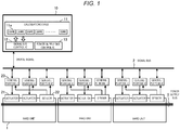
- Fig. 1 is an image diagram illustrating a structural example of a control system for a moving object according to an embodiment.
- the moving object has a plurality of hard units 1 and this control system controls the individual hard units 1.
- the hard units 1 are, for example, an engine, a transmission, a brake, and the like.
- the control system in Fig. 1 is provided with a signal bus 2 through which digital signals are transmitted.
- the protocol of the signal bus 2 is, for example, CAN (controller area network), Ethernet (registered trademark), or the like.
- a controller 10 includes a calculation device 11 that calculates the operation of the moving object, a signal bus control IC 12 that inputs or outputs digital signals with the signal bus 2, and a power supply bus control IC 13 that controls the power supply bus 5.
- the calculation device 11 has, for example, a plurality of calculation cores 11a and is capable of executing ultra-high-speed calculation.
- Each of the hard units 1 is provided with an actuator 21 for controlling the hard unit 1 and a sensor 22 for detecting the state of the hard unit 1.
- the actuator 21 is, for example, an injector or a spark plug provided in the engine, a braking device provided in each wheel, a power steering device for assisting steering operations, a power window device provided in each door, or the like.
- the sensor 22 is, for example, a crank position sensor that detects the rotational position of the crankshaft, a throttle position sensor that detects the degree of opening of the throttle valve, or the like.
- General-purpose ICs 23 are attached to the actuator 21 and the sensor 22.
- the general-purpose ICs 23 are connected to the signal bus 2. That is, in the communication path between the controller 10 and the general-purpose ICs 23, digital signals are transmitted without intervention of relay ECUs (electronic control unit).
- the controller 10 causes the calculation device 11 to perform calculation that determines the operation of the moving object and generates digital signals that define the operations of the actuators 21 according to the result of the calculation.
- the digital signals represent the physical quantity data that defines the operations of the actuators 21.
- the physical quantity data is, for example, the energy representing the work performed by the actuators 21, the target temperature and target pressure of adjustment by the actuators 21, the number of revolutions of the engine, the valve opening, and the like.
- the digital signals identify the electric signals given to the devices of the actuators.
- the electric signals are, for example, the signal waveforms of the electric signals, the time indicating the generation timing of the electric signals, the frequency and voltage of the electric signals, and the like.
- the general-purpose IC 23 attached to the actuator 21 obtains the digital signal that defines the operation of the hard unit 1 from the signal bus 2. Then, the general-purpose IC 23 generates a control signal for the actuator 21 based on the operation defined by the obtained digital signal. The general-purpose IC 23 continues to give the generated control signal to the actuator 21 until a new digital signal is obtained.
- the general-purpose IC 23 attached to the sensor 22 generates the digital signal indicating the state of the hard unit 1 based on the data signal obtained from the sensor 22 and outputs the generated digital signal to the signal bus 2.
- This digital signal represents, for example, the physical quantity data indicating the state of the hard unit 1.
- the physical quantity data is the temperature, the pressure, the number of revolutions, and the like.
- the controller 10 obtains the digital signals representing the states of the hard units 1 from the signal bus 2.
- the calculation device 11 performs calculation that determines the next operation of the moving object based on the states of the hard units 1 represented by the obtained digital signals. Then, the controller 10 generates the digital signal that defines the operations of the actuators 21 according to the result of the calculation.
- the cycle in which the controller 10 generates the digital signals is much longer than the cycle in which the general-purpose ICs 23 give the control signals to the actuators 21.
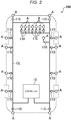
- Fig. 2 illustrates a structural example when the control system according to the embodiment is applied to a vehicle.
- a vehicle AM is provided with a plurality of actuators A.
- the actuators A are connected to ICs 110.
- the ICs 110 are connected to the controller 10 via a communication line CL.
- the communication line CL is an example of the unit for achieving the signal bus 2 in Fig. 1 and has a communication speed of, for example, 1 Gbps or more.
- the vehicle AM illustrated in Fig. 2 is an automobile that enables a manual operation for a travel by the driver's operation, an assisted operation for a travel by assisting the driver's operation, and an automatic operation for a travel without the driver's intervention.
- This vehicle AM adopts a by-wire system that performs an electric operation in drive control, braking control, and steering control. That is, in the vehicle AM, an operation of the accelerator pedal, an operation of the brake pedal, and an operation of the steering wheel are detected by the sensor. Then, the actuators A in charge of individual types of control are controlled via the control signals generated by the controller 10 based on the outputs of the sensors.
- controller 10 is disposed in the rear part of the vehicle AM in Fig. 2 , the disposition of the controller 10 is not limited to this example.
- Fig. 7 is an image diagram illustrating the structure of a control device for a conventional hard unit.
- one hard unit 500 is provided with one ECU 510 and the actuators and the sensors of the hard unit 500 are connected to the ECU 510 via many signal lines.
- the ECU 510 includes many cabinets, electronic boards, and heat dissipation devices, the ECU 510 has many input-output circuits and power supply circuits, and many connectors and signal lines that connect the hard unit 500 to the ECU 510 are present.
- a plurality of hard units installed in the moving object may be preferably controlled by a single controller to simplify the structure of the control system. This can eliminate the duplication of cabinets, electronic boards, heat dissipation devices, input-output circuits, power supply circuits, and the like that constitute the controller.
- the communication control between the controller and the actuators and between the controller and the sensors becomes very complicated and the amount of communication becomes enormous.
- the hard unit that needs high-speed control such as the internal combustion engine of the vehicle
- extremely fine control is required for the actuators.
- the responsiveness degrades.
- the controller performs calculation that determines the operation of the moving object and generates digital signals that define the operations of the actuators according to the result of the calculation.
- the digital signals represent, for example, the physical quantity data for control and have a higher degree of abstraction than the control signal actually given to the actuators.
- the digital signals are transmitted within the moving object using the high-speed digital signal transmission path.
- the ICs attached to the actuators obtain the digital signals generated by the controller via the digital signal transmission path and generate control signals for the actuators based on the operation specified by the digital signals.
- the communication control between the controller and the ICs attached to the actuators becomes simple and easy and significantly reduce the amount of communication. Accordingly, the individual actuators can be controlled responsively by the single controller.
- the digital signal transmission path does not include a relay ECU, the signals are transmitted in the communication path from the controller to the actuators without relaying by the ECU. Accordingly, the cost can be reduced significantly and the power consumption can also be reduced.
- the ICs attached to the actuators can be made versatile by defining standards or rules concerning the information represented by the digital signals output by the controller. That is, the ICs attached to the actuators only need to have the function (so-called signal translating function) of converting the operations of the actuators defined by the obtained digital signals to the control signals given to the actuators. This can reduce the cost of the ICs attached to the actuators and improve the cost performance of the control system.
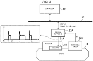
- Fig. 3 illustrates an example of injector injection control.
- An injector 21A is provided in the fuel device that supplies fuel to an engine 1A.
- the injector 21A injects, from a valve, the fuel pumped by a pump and the degree of opening or closing of the valve is controlled by a solenoid 211.
- the engine combustion chamber is provided with a crank angle sensor 22A.
- the crank angle sensor 22A outputs a trigger signal Tr when the piston of the cylinder reaches the top dead center.
- a general-purpose IC 23A is attached to the injector 21A.
- the general-purpose IC 23A functions as a solenoid voltage control unit that applies a voltage to the solenoid 211 in the injector 21A.
- the general-purpose IC 23A After receiving the trigger signal Tr from the crank angle sensor 22A, the general-purpose IC 23A gives the solenoid 211 a control signal with a signal waveform as illustrated in the dashed frame in Fig. 3 . It should be noted here that, in the signal waveform in Fig. 3 , the signal is raised with an impulse to improve the initial response of the solenoid 211 and then the state of the solenoid 211 is held at a constant voltage.
- the controller 10 generates a digital signal for injector injection control.
- This digital signal defines the operation of the injector 21A and, in this example, identifies the signal waveform of the control signal to be given to the solenoid 211.
- the digital signal for injector injection control includes profiles (target waveform) and timings t1, t2, ..., Tn.
- the controller 10 outputs the generated digital signal to the signal bus 2.
- the general-purpose IC 23A receives, via the signal bus 2, the digital signal for injector injection control output from the controller 10. Then, the general-purpose IC 23A generates a control signal according to the profiles and timings t1, t2, ..., tn indicated by this digital signal and gives the generated control signal to the solenoid 211 each time the trigger signal Tr is received from the crank angle sensor 22A.
- the injector injection control described above is an example of the control (referred to as the profile control in this specification) for causing the actuator to perform a desired operation by controlling the voltage or current applied to an electric device such as a solenoid according to the instructed target waveform (profile).
- This example can also be used for profile control other than injector injection control.
- this example can also be used for ignition control of the engine. That is, in the ignition system, the general-purpose IC gives an ignition signal to the ignition coil.
- the controller 10 outputs a digital signal for ignition control of the engine to the signal bus 2. This digital signal includes the profile and timing that identify the ignition signal.
- the general-purpose IC receives the digital signal for ignition control of the engine, generates an ignition signal, and gives the generated ignition signal to the ignition coil.
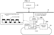
- Fig. 4 illustrates an example of idle speed control.
- An idle speed control valve 21B controls the number of idle revolutions by adjusting the amount of air flowing through the bypass passage of the throttle valve.
- the opening or closing of the idle speed control valve 21B is controlled by the solenoid 212.
- the engine combustion chamber is provided with the crank angle sensor 22A.
- the crank angle sensor 22A outputs the trigger signal Tr when the crank angle reaches a predetermined angle.
- the timing at which the idle speed control system changes the flow rate of air is preferably synchronized with the crank angle. This is because the best match between air and fuel is easily optimized and a misfire and the like are unlikely to occur.
- a general-purpose IC 23B is attached to the idle speed control valve 21B.
- the general-purpose IC 23B functions as a solenoid voltage control unit that applies a voltage to the solenoid 212 in the idle speed control valve 21B.
- the general-purpose IC 23B After receiving the trigger signal Tr from the crank angle sensor 22A, the general-purpose IC 23B gives the solenoid 212 a control signal with a signal waveform as illustrated in the dashed frame in Fig. 4 .
- the signal waveform in Fig. 4 is a duty waveform (pulse signal with a fixed period) on which a dither waveform is superimposed. Dithering gives slight vibrations at a frequency higher than in the control signal to improve the responsiveness of the solenoid 212.
- the controller 10 generates a digital signal for idle speed control.
- This digital signal defines the operation of the idle speed control valve 21B and, in this example, identifies the signal waveform of the control signal given to the solenoid 212.
- the digital signal for idle speed control represents a reference frequency f1, a reference voltage v1, and a duty ratio D1 that indicate a duty waveform, and a frequency f2 and a voltage v2 that indicate a dither waveform.
- the controller 10 outputs the generated digital signal to the signal bus 2.
- the general-purpose IC 23B receives the digital signal for idle speed control via the signal bus 2. Then, the general-purpose IC 23B generates a control signal according to the reference frequency f1, the reference voltage v1, and the duty ratio D1 of the duty waveform, and the frequency f2 and the voltage v2 of the dither waveform indicated by this digital signal, and gives the generated control signal to the solenoid 212.
- the general-purpose IC 23B updates the duty waveform of the control signal according to the digital signal for idle speed control each time the general-purpose IC 23B receives the trigger signal Tr from the crank angle sensor 22A.
- the idle speed control described above is an example of the control (referred to as the duty control in this specification) that causes the actuator to perform a desired operation by controlling the voltage or the current applied to an electrical device such as a solenoid according to the instructed duty waveform.
- This duty control can also be used for control other than idle speed control.
- the duty control can be used for valve control by the air pressure or the hydraulic pressure.
- Fig. 5 illustrates an example of throttle control.
- the throttle system is a mechanism that adjusts the amount of intake air supplied to the engine 1A.
- the throttle valve opening is adjusted by a motor 213.
- the engine combustion chamber is provided with the crank angle sensor 22A.
- the crank angle sensor 22A outputs the trigger signal Tr when the crank angle reaches a predetermined angle.
- the throttle valve 213 is provided with a throttle position sensor 22B that detects the current position of the throttle.
- a general-purpose IC 23C is attached to the throttle valve 21C.
- the general-purpose IC 23C functions as a control unit that drives the motor 213 in the throttle valve 21C and controls the motor position.
- the general-purpose IC 23C drives the motor 213 of the throttle valve 21C according to the instructed target opening.
- the controller 10 generates a digital signal for throttle control. This digital signal defines the operation of the throttle valve 21C and indicates the target opening of the throttle valve 21C.
- the controller 10 outputs the generated digital signals to the signal bus 2.
- the general-purpose IC 23C receives the digital signal for throttle control via the signal bus 2. Then, the general-purpose IC 23C drives the motor 213 with reference to the signal transmitted from the throttle position sensor 22B so that the opening of the throttle valve 21C becomes the target opening indicated by this digital signal. When receiving the trigger signal Tr from the crank angle sensor 22A, the general-purpose IC 23C updates the target opening of the throttle bar 21C by receiving a new digital signal.
- the throttle control described above is an example of the motor position control that causes the actuator to perform a desired operation by controlling the drive signal given to the motor according to the instructed position target.
- This motor position control can also be used for control other than throttle control.
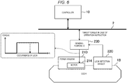
- FIG. 6 illustrates an example of power window control.
- a power window 21D provided in a door 1B performs an open-close operation of the window via a motor 214.
- the power window 21D is provided with a lock detection sensor 22C.
- the lock detection sensor 22C receives the feedback of an energy change from the motor 214, detects that a hand or the like has been caught in the power window 21D based on the feedback, and outputs a motor lock signal during detection.
- a general-purpose IC 23D is attached to the power window 21D.
- the general-purpose IC 23D drives the motor 214 of the power window 21D according to the instructed target torque.
- the general-purpose IC 23D reduces the torque of the motor 214 regardless of the instructed target torque.
- the controller 10 generates a digital signal for power window control. This digital signal defines the operation of the power window 21D and indicates a window open-close operation instruction and the target torque while the power window operates.
- the controller 10 outputs the generated digital signal to the signal bus 2.
- the general-purpose IC 23D receives the digital signal for power window control via the signal bus 2. Then, when an open-close operation instruction is present, the general-purpose IC 23D drives the motor 214 of the power window 21D according to the instructed target torque. However, when receiving the motor lock signal from the lock detection sensor 22C while driving the motor 214, the general-purpose IC 23D reduces the torque of the motor 214.
- the power window control described above is an example of the motor torque control that causes the actuator to perform a desired operation by controlling the drive signal given to the motor according to the instructed torque target.
- This motor torque control can also be used not only for power window control but also for the control of, for example, a power seat belt.
- fan control heater control
- supercharger control the controller 10 only needs to output digital signals indicating the turn-on or -off of a supercharger and the opening of an air bypass valve when the supercharger turns on.
- the plurality of hard units 1 installed in the moving object is controlled by the single controller 10.
- the controller 10 only needs to output the digital signals that define the operations of the actuators 21 to the signal bus 2 to control the plurality of hard units 1 and the real-time control of the actuators 21 is performed by the ICs 23 attached to the actuators 21. Therefore, according to this control system, the actuators 21 can be controlled responsively by the single controller 10.
- the signal bus 2 does not include a relay ECU, signals are transmitted through the communication path from controller 10 to the actuators 23 without relaying by the ECU. Accordingly, the cost can be reduced significantly and the power consumption can also be reduced.
- the digital signal transmission path may be other than the signal bus 2 or the communication line CL and may be achieved by, for example, an optical fiber cable, wireless communication, or the like.
- the moving object according to the present disclosure is not limited to a vehicle and the control system according to the present disclosure is applicable to, for example, a ship, an airplane, a robot, or the like.
- the technology disclosed herein is useful in achieving a control system that controls a plurality of hard units installed in a moving object using a simple structure.
Landscapes
- Engineering & Computer Science (AREA)
- Automation & Control Theory (AREA)
- Mechanical Engineering (AREA)
- General Engineering & Computer Science (AREA)
- General Physics & Mathematics (AREA)
- Physics & Mathematics (AREA)
- Human Computer Interaction (AREA)
- Transportation (AREA)
- Computer Hardware Design (AREA)
- Microelectronics & Electronic Packaging (AREA)
- Chemical & Material Sciences (AREA)
- Combustion & Propulsion (AREA)
- Combined Controls Of Internal Combustion Engines (AREA)
Abstract
Description
- The technology disclosed herein relates to a control system that controls many devices installed in a moving object such as a vehicle.
- In recent years, almost all actuators installed in vehicles are electronically controlled. Accordingly, many ECUs (electronic control units) for controlling individual actuators are installed in vehicles.
-
Patent document 1 discloses the structure of a control system for controlling various in-vehicle devices installed in a vehicle. This control system is divided into a plurality of domains (energy domain, body domain, and motion domain) according to the roles (functions) of individual in-vehicle devices and each of the domains has a layered structure in which the device control unit for controlling the in-vehicle devices and the domain control unit for centrally controlling the device control unit are present. Furthermore, this control system has an integrated control unit for coordinating and collaborating the control by the individual domain control units. The device control units, domain control units, and integrated control units are actually embodied by being implemented in ECUs as programs and databases. - [Patent document 1]
JP-A-2017-61278 - In the structure in which an ECU is provided for each device in a vehicle, the number of dedicated ECUs is enormous and one vehicle has several hundreds of ECUs for a model with many ECUs. Accordingly, the number of wires and connectors that connect between individual ECUs and between individual ECUs and sensors also increases. As a result, the structure of the communication system of a vehicle becomes complicated and the cost increases.
- In addition, in the structure in which the control units are layered as in
patent document 1, a plurality of ECUs is present in the communication paths from the integrated control unit to individual in-vehicle devices. This leads to an increase in cost and power consumption. In an ideal case, signals are preferably transmitted without relaying by ECUs in the communication paths from the calculation device to individual in-vehicle devices. Accordingly, the cost can be reduced significantly and the power consumption can also be reduced. - For example, in the case of a vehicle, however, fine control is required for actuators for an internal combustion engine or the like. Accordingly, even if the functions of individual ECUs are simply integrated into one calculation device, the communication control between the actuators and the calculation device becomes complicated and the amount of communication becomes enormous, thereby causing degradation of responsiveness of control.
- An object of the technology disclosed herein is to achieve a control system that controls a plurality of hard units installed in a moving object, using a simple structure.
- To solve the above problems, according to the technique disclosed herein, there is provided a control system that controls a plurality of hard units installed in a moving object, the control system including a digital signal transmission path that transmits a digital signal without including a relay ECU (electronic control unit); a controller that includes at least a calculation device for calculating an operation of the moving object and a signal bus control IC (integrated circuit) for inputting and outputting the digital signal to and from the digital signal transmission path; and a plurality of ICs that are attached to actuators for controlling the hard units and connected to the digital signal transmission path, in which the controller causes the calculation device to perform calculation that determines an operation of the moving object, generates a digital signal that defines an operation of the actuators according to a result of the calculation, and causes the signal bus control IC to output the generated digital signal to the digital signal transmission path, and the plurality of ICs obtains the digital signal that defines the operations of the actuators from the digital signal transmission path and generates a control signal for the actuators based on the operations defined by the obtained digital signal.
- According to this structure, the controller causes the calculation device to perform calculation that determines the operation of the moving object and generates the digital signal that defines the operation of the actuators according to the result of the calculation. The generated digital signal is output to the digital signal transmission path by the signal bus control IC. The ICs attached to the actuators obtain the digital signal that defines the operation of the actuators from the digital signal transmission path and generate the control signal for the actuators based on the operation defined by this digital signal. That is, the controller only needs to output the digital signal that defines the operation of the actuators to the digital signal transmission path to control the plurality of hard units and does not need to control the actuators via full time communication. The real-time control of the actuators is performed by the ICs attached to the actuators. Accordingly, the control system can control the actuators responsively using the single controller.
- In addition, since the digital signal transmission path does not include a relay ECU, the signal is transmitted without relaying by the ECU in the communication path between the controller and the actuators. Accordingly, the cost can be reduced significantly and the power consumption can also be reduced.
- In addition, the ICs attached to the actuators can be made versatile by defining standards or rules concerning the information represented by the digital signal output by the controller. That is, the ICs attached to the actuators only need to have the function (so-called signal translating function) of converting the operation of the actuators specified by the obtained digital signal to the control signal given to the actuators. Accordingly, the cost of the ICs attached to the actuators can be reduced and the cost performance of the control system can be improved.
- In addition, preferably, the actuators include a first actuator having a solenoid, the controller outputs, to the digital signal transmission path, a first digital signal that identifies an electric signal given to the solenoid of the first actuator, and a first IC attached to the first actuator among the plurality of ICs obtains the first digital signal from the digital signal transmission path, generates the electric signal identified by the first digital signal, and gives the generated electric signal to the solenoid of the first actuator.
- Accordingly, in controlling the first actuator having the solenoid, the controller only needs to output, to the digital signal transmission path, the first digital signal that identifies the electric signal given to the solenoid of the first actuator. The real-time control of the first actuator is performed by the first IC attached to the first actuator. Accordingly, the control system can control the actuator having the solenoid responsively.
- In addition, preferably, the actuators include a second actuator having a motor, the controller outputs a second digital signal that identifies a target state of the second actuator to the digital signal transmission path, and a second IC attached to the second actuator among the plurality of ICs obtains the second digital signal from the digital signal transmission path, generates an electric signal that drives the motor so that the second actuator reaches a target state identified by the second digital signal, and gives the generated electric signal to the motor of the second actuator.
- Accordingly, in controlling the second actuator having the motor, the controller only needs to output the second digital signal that identifies the target state of the second actuator to the digital signal transmission path. The real-time control of the second actuator is performed by the second IC attached to the second actuator. Accordingly, the control system can control the actuator having the motor responsively.
- As described above, the technology disclosed herein can achieve the control system that controls the plurality of hard units installed in the moving object using a simple structure.
-
- [
Fig. 1] Fig. 1 illustrates a structural example of a control system for a moving object according to an embodiment. - [
Fig. 2] Fig. 2 illustrates a structural example when the control system according to the embodiment is applied to a vehicle. - [
Fig. 3] Fig. 3 illustrates an example of injector injection control. - [
Fig. 4] Fig. 4 illustrates an example of idle speed control. - [
Fig. 5] Fig. 5 illustrates an example of throttle control. - [
Fig. 6] Fig. 6 illustrates an example of power window control. - [
Fig. 7] Fig. 7 is a structure image diagram illustrating the control device of a conventional hard unit. - An exemplary embodiment will be described in detail below with reference to the drawings.
-
Fig. 1 is an image diagram illustrating a structural example of a control system for a moving object according to an embodiment. The moving object has a plurality ofhard units 1 and this control system controls the individualhard units 1. In the case of an automobile, which is an example of the moving object, thehard units 1 are, for example, an engine, a transmission, a brake, and the like. - The control system in
Fig. 1 is provided with asignal bus 2 through which digital signals are transmitted. The protocol of thesignal bus 2 is, for example, CAN (controller area network), Ethernet (registered trademark), or the like. Acontroller 10 includes acalculation device 11 that calculates the operation of the moving object, a signalbus control IC 12 that inputs or outputs digital signals with thesignal bus 2, and a power supply bus control IC 13 that controls the power supply bus 5. Thecalculation device 11 has, for example, a plurality ofcalculation cores 11a and is capable of executing ultra-high-speed calculation. - Each of the
hard units 1 is provided with anactuator 21 for controlling thehard unit 1 and asensor 22 for detecting the state of thehard unit 1. Theactuator 21 is, for example, an injector or a spark plug provided in the engine, a braking device provided in each wheel, a power steering device for assisting steering operations, a power window device provided in each door, or the like. Thesensor 22 is, for example, a crank position sensor that detects the rotational position of the crankshaft, a throttle position sensor that detects the degree of opening of the throttle valve, or the like. - General-
purpose ICs 23 are attached to theactuator 21 and thesensor 22. The general-purpose ICs 23 are connected to thesignal bus 2. That is, in the communication path between thecontroller 10 and the general-purpose ICs 23, digital signals are transmitted without intervention of relay ECUs (electronic control unit). - The
controller 10 causes thecalculation device 11 to perform calculation that determines the operation of the moving object and generates digital signals that define the operations of theactuators 21 according to the result of the calculation. For example, the digital signals represent the physical quantity data that defines the operations of theactuators 21. Specifically, the physical quantity data is, for example, the energy representing the work performed by theactuators 21, the target temperature and target pressure of adjustment by theactuators 21, the number of revolutions of the engine, the valve opening, and the like. In addition, for example, the digital signals identify the electric signals given to the devices of the actuators. Specifically, the electric signals are, for example, the signal waveforms of the electric signals, the time indicating the generation timing of the electric signals, the frequency and voltage of the electric signals, and the like. - The general-
purpose IC 23 attached to theactuator 21 obtains the digital signal that defines the operation of thehard unit 1 from thesignal bus 2. Then, the general-purpose IC 23 generates a control signal for theactuator 21 based on the operation defined by the obtained digital signal. The general-purpose IC 23 continues to give the generated control signal to theactuator 21 until a new digital signal is obtained. - The general-
purpose IC 23 attached to thesensor 22 generates the digital signal indicating the state of thehard unit 1 based on the data signal obtained from thesensor 22 and outputs the generated digital signal to thesignal bus 2. This digital signal represents, for example, the physical quantity data indicating the state of thehard unit 1. Specifically, the physical quantity data is the temperature, the pressure, the number of revolutions, and the like. - The
controller 10 obtains the digital signals representing the states of thehard units 1 from thesignal bus 2. Thecalculation device 11 performs calculation that determines the next operation of the moving object based on the states of thehard units 1 represented by the obtained digital signals. Then, thecontroller 10 generates the digital signal that defines the operations of theactuators 21 according to the result of the calculation. The cycle in which thecontroller 10 generates the digital signals is much longer than the cycle in which the general-purpose ICs 23 give the control signals to theactuators 21. -
Fig. 2 illustrates a structural example when the control system according to the embodiment is applied to a vehicle. InFig. 2 , a vehicle AM is provided with a plurality of actuators A. The actuators A are connected toICs 110. TheICs 110 are connected to thecontroller 10 via a communication line CL. The communication line CL is an example of the unit for achieving thesignal bus 2 inFig. 1 and has a communication speed of, for example, 1 Gbps or more. - The vehicle AM illustrated in
Fig. 2 is an automobile that enables a manual operation for a travel by the driver's operation, an assisted operation for a travel by assisting the driver's operation, and an automatic operation for a travel without the driver's intervention. This vehicle AM adopts a by-wire system that performs an electric operation in drive control, braking control, and steering control. That is, in the vehicle AM, an operation of the accelerator pedal, an operation of the brake pedal, and an operation of the steering wheel are detected by the sensor. Then, the actuators A in charge of individual types of control are controlled via the control signals generated by thecontroller 10 based on the outputs of the sensors. - Although the
controller 10 is disposed in the rear part of the vehicle AM inFig. 2 , the disposition of thecontroller 10 is not limited to this example. -
Fig. 7 is an image diagram illustrating the structure of a control device for a conventional hard unit. In the structure inFig. 7 , onehard unit 500 is provided with oneECU 510 and the actuators and the sensors of thehard unit 500 are connected to theECU 510 via many signal lines. When many structures as illustrated inFig. 7 are installed in a moving object, many duplicate components are present and the system structure becomes complicated. Specifically, theECU 510 includes many cabinets, electronic boards, and heat dissipation devices, theECU 510 has many input-output circuits and power supply circuits, and many connectors and signal lines that connect thehard unit 500 to theECU 510 are present. - A plurality of hard units installed in the moving object may be preferably controlled by a single controller to simplify the structure of the control system. This can eliminate the duplication of cabinets, electronic boards, heat dissipation devices, input-output circuits, power supply circuits, and the like that constitute the controller. However, even if the functions of individual ECUs are simply integrated into a single controller, the communication control between the controller and the actuators and between the controller and the sensors becomes very complicated and the amount of communication becomes enormous. In addition, for the hard unit that needs high-speed control, such as the internal combustion engine of the vehicle, extremely fine control is required for the actuators. When the control signals for the actuators are sent from the controller in this case, the responsiveness degrades.
- Accordingly, in the present disclosure, the controller performs calculation that determines the operation of the moving object and generates digital signals that define the operations of the actuators according to the result of the calculation. The digital signals represent, for example, the physical quantity data for control and have a higher degree of abstraction than the control signal actually given to the actuators. Then, the digital signals are transmitted within the moving object using the high-speed digital signal transmission path. Then, the ICs attached to the actuators obtain the digital signals generated by the controller via the digital signal transmission path and generate control signals for the actuators based on the operation specified by the digital signals.
- This can make the communication control between the controller and the ICs attached to the actuators becomes simple and easy and significantly reduce the amount of communication. Accordingly, the individual actuators can be controlled responsively by the single controller. In addition, since the digital signal transmission path does not include a relay ECU, the signals are transmitted in the communication path from the controller to the actuators without relaying by the ECU. Accordingly, the cost can be reduced significantly and the power consumption can also be reduced.
- In addition, the ICs attached to the actuators can be made versatile by defining standards or rules concerning the information represented by the digital signals output by the controller. That is, the ICs attached to the actuators only need to have the function (so-called signal translating function) of converting the operations of the actuators defined by the obtained digital signals to the control signals given to the actuators. This can reduce the cost of the ICs attached to the actuators and improve the cost performance of the control system.
- A specific example of the control form of the actuators according to the embodiment will be described below.
-
Fig. 3 illustrates an example of injector injection control. Aninjector 21A is provided in the fuel device that supplies fuel to anengine 1A. Theinjector 21A injects, from a valve, the fuel pumped by a pump and the degree of opening or closing of the valve is controlled by asolenoid 211. - The engine combustion chamber is provided with a
crank angle sensor 22A. Thecrank angle sensor 22A outputs a trigger signal Tr when the piston of the cylinder reaches the top dead center. - A general-
purpose IC 23A is attached to theinjector 21A. The general-purpose IC 23A functions as a solenoid voltage control unit that applies a voltage to thesolenoid 211 in theinjector 21A. After receiving the trigger signal Tr from thecrank angle sensor 22A, the general-purpose IC 23A gives the solenoid 211 a control signal with a signal waveform as illustrated in the dashed frame inFig. 3 . It should be noted here that, in the signal waveform inFig. 3 , the signal is raised with an impulse to improve the initial response of thesolenoid 211 and then the state of thesolenoid 211 is held at a constant voltage. - The
controller 10 generates a digital signal for injector injection control. This digital signal defines the operation of theinjector 21A and, in this example, identifies the signal waveform of the control signal to be given to thesolenoid 211. Specifically, the digital signal for injector injection control includes profiles (target waveform) and timings t1, t2, ..., Tn. Thecontroller 10 outputs the generated digital signal to thesignal bus 2. - The general-
purpose IC 23A receives, via thesignal bus 2, the digital signal for injector injection control output from thecontroller 10. Then, the general-purpose IC 23A generates a control signal according to the profiles and timings t1, t2, ..., tn indicated by this digital signal and gives the generated control signal to thesolenoid 211 each time the trigger signal Tr is received from thecrank angle sensor 22A. - The injector injection control described above is an example of the control (referred to as the profile control in this specification) for causing the actuator to perform a desired operation by controlling the voltage or current applied to an electric device such as a solenoid according to the instructed target waveform (profile). This example can also be used for profile control other than injector injection control.
- For example, this example can also be used for ignition control of the engine. That is, in the ignition system, the general-purpose IC gives an ignition signal to the ignition coil. The
controller 10 outputs a digital signal for ignition control of the engine to thesignal bus 2. This digital signal includes the profile and timing that identify the ignition signal. The general-purpose IC receives the digital signal for ignition control of the engine, generates an ignition signal, and gives the generated ignition signal to the ignition coil. -
Fig. 4 illustrates an example of idle speed control. An idlespeed control valve 21B controls the number of idle revolutions by adjusting the amount of air flowing through the bypass passage of the throttle valve. The opening or closing of the idlespeed control valve 21B is controlled by thesolenoid 212. - The engine combustion chamber is provided with the
crank angle sensor 22A. Thecrank angle sensor 22A outputs the trigger signal Tr when the crank angle reaches a predetermined angle. The timing at which the idle speed control system changes the flow rate of air is preferably synchronized with the crank angle. This is because the best match between air and fuel is easily optimized and a misfire and the like are unlikely to occur. - A general-
purpose IC 23B is attached to the idlespeed control valve 21B. The general-purpose IC 23B functions as a solenoid voltage control unit that applies a voltage to thesolenoid 212 in the idlespeed control valve 21B. After receiving the trigger signal Tr from thecrank angle sensor 22A, the general-purpose IC 23B gives the solenoid 212 a control signal with a signal waveform as illustrated in the dashed frame inFig. 4 . The signal waveform inFig. 4 is a duty waveform (pulse signal with a fixed period) on which a dither waveform is superimposed. Dithering gives slight vibrations at a frequency higher than in the control signal to improve the responsiveness of thesolenoid 212. - The
controller 10 generates a digital signal for idle speed control. This digital signal defines the operation of the idlespeed control valve 21B and, in this example, identifies the signal waveform of the control signal given to thesolenoid 212. Specifically, the digital signal for idle speed control represents a reference frequency f1, a reference voltage v1, and a duty ratio D1 that indicate a duty waveform, and a frequency f2 and a voltage v2 that indicate a dither waveform. Thecontroller 10 outputs the generated digital signal to thesignal bus 2. - The general-
purpose IC 23B receives the digital signal for idle speed control via thesignal bus 2. Then, the general-purpose IC 23B generates a control signal according to the reference frequency f1, the reference voltage v1, and the duty ratio D1 of the duty waveform, and the frequency f2 and the voltage v2 of the dither waveform indicated by this digital signal, and gives the generated control signal to thesolenoid 212. The general-purpose IC 23B updates the duty waveform of the control signal according to the digital signal for idle speed control each time the general-purpose IC 23B receives the trigger signal Tr from thecrank angle sensor 22A. - The idle speed control described above is an example of the control (referred to as the duty control in this specification) that causes the actuator to perform a desired operation by controlling the voltage or the current applied to an electrical device such as a solenoid according to the instructed duty waveform. This duty control can also be used for control other than idle speed control. For example, the duty control can be used for valve control by the air pressure or the hydraulic pressure.
-
Fig. 5 illustrates an example of throttle control. The throttle system is a mechanism that adjusts the amount of intake air supplied to theengine 1A. In thethrottle valve 21C, the throttle valve opening is adjusted by amotor 213. - The engine combustion chamber is provided with the
crank angle sensor 22A. Thecrank angle sensor 22A outputs the trigger signal Tr when the crank angle reaches a predetermined angle. Thethrottle valve 213 is provided with athrottle position sensor 22B that detects the current position of the throttle. - A general-
purpose IC 23C is attached to thethrottle valve 21C. The general-purpose IC 23C functions as a control unit that drives themotor 213 in thethrottle valve 21C and controls the motor position. The general-purpose IC 23C drives themotor 213 of thethrottle valve 21C according to the instructed target opening. - The
controller 10 generates a digital signal for throttle control. This digital signal defines the operation of thethrottle valve 21C and indicates the target opening of thethrottle valve 21C. Thecontroller 10 outputs the generated digital signals to thesignal bus 2. - The general-
purpose IC 23C receives the digital signal for throttle control via thesignal bus 2. Then, the general-purpose IC 23C drives themotor 213 with reference to the signal transmitted from thethrottle position sensor 22B so that the opening of thethrottle valve 21C becomes the target opening indicated by this digital signal. When receiving the trigger signal Tr from thecrank angle sensor 22A, the general-purpose IC 23C updates the target opening of thethrottle bar 21C by receiving a new digital signal. - The throttle control described above is an example of the motor position control that causes the actuator to perform a desired operation by controlling the drive signal given to the motor according to the instructed position target. This motor position control can also be used for control other than throttle control.
-
Fig. 6 illustrates an example of power window control. Apower window 21D provided in a door 1B performs an open-close operation of the window via amotor 214. - The
power window 21D is provided with alock detection sensor 22C. Thelock detection sensor 22C receives the feedback of an energy change from themotor 214, detects that a hand or the like has been caught in thepower window 21D based on the feedback, and outputs a motor lock signal during detection. - A general-
purpose IC 23D is attached to thepower window 21D. When instructed to operate thepower window 21D, the general-purpose IC 23D drives themotor 214 of thepower window 21D according to the instructed target torque. When receiving the motor lock signal while thepower window 21D operates, the general-purpose IC 23D reduces the torque of themotor 214 regardless of the instructed target torque. - The
controller 10 generates a digital signal for power window control. This digital signal defines the operation of thepower window 21D and indicates a window open-close operation instruction and the target torque while the power window operates. Thecontroller 10 outputs the generated digital signal to thesignal bus 2. - The general-
purpose IC 23D receives the digital signal for power window control via thesignal bus 2. Then, when an open-close operation instruction is present, the general-purpose IC 23D drives themotor 214 of thepower window 21D according to the instructed target torque. However, when receiving the motor lock signal from thelock detection sensor 22C while driving themotor 214, the general-purpose IC 23D reduces the torque of themotor 214. - The power window control described above is an example of the motor torque control that causes the actuator to perform a desired operation by controlling the drive signal given to the motor according to the instructed torque target. This motor torque control can also be used not only for power window control but also for the control of, for example, a power seat belt.
- In addition to the examples described above, for example, fan control, heater control, supercharger control, and the like can also be achieved similarly. For example, in supercharger control, the
controller 10 only needs to output digital signals indicating the turn-on or -off of a supercharger and the opening of an air bypass valve when the supercharger turns on. - As described above, according to the embodiment, the plurality of
hard units 1 installed in the moving object is controlled by thesingle controller 10. Then, thecontroller 10 only needs to output the digital signals that define the operations of theactuators 21 to thesignal bus 2 to control the plurality ofhard units 1 and the real-time control of theactuators 21 is performed by theICs 23 attached to theactuators 21. Therefore, according to this control system, theactuators 21 can be controlled responsively by thesingle controller 10. In addition, since thesignal bus 2 does not include a relay ECU, signals are transmitted through the communication path fromcontroller 10 to theactuators 23 without relaying by the ECU. Accordingly, the cost can be reduced significantly and the power consumption can also be reduced. - In the present disclosure, the digital signal transmission path may be other than the
signal bus 2 or the communication line CL and may be achieved by, for example, an optical fiber cable, wireless communication, or the like. - The moving object according to the present disclosure is not limited to a vehicle and the control system according to the present disclosure is applicable to, for example, a ship, an airplane, a robot, or the like.
- The embodiment described above is only an example and the scope of the present disclosure should not be understood in a limited manner. The scope of the present disclosure is defined by the claims and all modifications and changes belonging to the equivalent scope of the claims fall within the scope of the present disclosure.
- The technology disclosed herein is useful in achieving a control system that controls a plurality of hard units installed in a moving object using a simple structure.
-
- 1:
- hard unit
- 2:
- signal bus (digital signal transmission path)
- 10:
- controller
- 11:
- calculation device
- 12:
- signal bus control IC
- 21:
- actuator
- 23, 23A, 23B, 23C, 23D:
- IC
- 110:
- IC
- 211, 212:
- solenoid
- 213, 214:
- motor
- A:
- actuator
- CL:
- communication line
Claims (11)
- A control system that controls a plurality of hard units installed in a moving object, the control system comprising:a digital signal transmission path that transmits a digital signal without including a relay ECU (electronic control unit);a controller that includes at least a calculation device for calculating an operation of the moving object and a signal bus control IC (integrated circuit) for inputting and outputting the digital signal to and from the digital signal transmission path; anda plurality of ICs that are attached to actuators for controlling the hard units and connected to the digital signal transmission path,wherein the controller causes the calculation device to perform calculation that determines an operation of the moving object, generates a digital signal that defines an operation of the actuators according to a result of the calculation, and causes the signal bus control IC to output the generated digital signal to the digital signal transmission path, andthe plurality of ICs obtains the digital signal that defines the operation of the actuators from the digital signal transmission path and generates a control signal for the actuators based on the operation defined by the obtained digital signal.
- A control system according to the preceding claim, wherein the controller is configured to generate the digital signal to include at least one characteristic of the control signal to be generated by the IC for controlling the actuator and to have a higher degree of abstraction than said control signal.
- A control system according to one of the preceding claims, wherein the IC is connected to a sensor to receive a sensor signal representative of the operation of the moving object and/or of the actuator, wherein said IC is configured to generate the control signal for said actuator in response to the at least one characteristic defined by the digital signal and said sensor signal.
- A control system according to one of the preceding claims, wherein the sensor is directly connected to the IC to send the sensor signal to the IC via a signal path other than said digital signal transmission path.
- The control system for the moving object according to any of the preceding claims,
wherein the actuators include a first actuator having a solenoid,
the controller outputs, to the digital signal transmission path, a first digital signal that identifies an electric signal given to the solenoid of the first actuator, and
a first IC attached to the first actuator among the plurality of ICs obtains the first digital signal from the digital signal transmission path, generates the electric signal identified by the first digital signal, and gives the generated electric signal to the solenoid of the first actuator. - The control system for the moving object according to any of the preceding claims,
wherein the actuators include a second actuator having a motor,
the controller outputs a second digital signal that identifies a target state of the second actuator to the digital signal transmission path, and
a second IC attached to the second actuator among the plurality of ICs obtains the second digital signal from the digital signal transmission path, generates an electric signal that drives the motor so that the second actuator reaches a target state identified by the second digital signal, and gives the generated electric signal to the motor of the second actuator. - A control system according to any of the preceding claims, wherein the digital signal send from the controller to the IC includes at least one of the following characteristics of the control signal to be generated by the IC: signal wave form and timing of an electric control signal for the solenoid of the actuator or a spark plug.
- A control system according to one of the preceding claims, wherein the IC is configured to generate the control signal for the actuator in response to a trigger signal received from a crank angle sensor.
- A control system according to any of the preceding claims, wherein the digital signal sent from the controller to the IC includes at least one of the following characteristics of the controller signal to be generated by the IC: reference frequency, reference voltage and duty ratio of the electric control signal for the actuator.
- A control system according to any of the preceding claims, wherein the digital signal sent from the controller to the IC includes at least one of the following characteristics of the control signal to be generated by the IC: target position and/or target torque of an electric motor, wherein the IC is configured to generate the control signal to the electric motor in response to the target position and/or target torque and in response to a sensor signal indicating the position and/or the torque of the actuator.
- A control system according to any of the preceding claims, wherein the transmission path includes a signal bus to which said plurality of ICs and said controller are connected.
Applications Claiming Priority (1)
| Application Number | Priority Date | Filing Date | Title |
|---|---|---|---|
| JP2020023625A JP7380294B2 (en) | 2020-02-14 | 2020-02-14 | Mobile control system |
Publications (1)
| Publication Number | Publication Date |
|---|---|
| EP3865697A1 true EP3865697A1 (en) | 2021-08-18 |
Family
ID=74285296
Family Applications (1)
| Application Number | Title | Priority Date | Filing Date |
|---|---|---|---|
| EP21153552.1A Pending EP3865697A1 (en) | 2020-02-14 | 2021-01-26 | Control system for moving object |
Country Status (4)
| Country | Link |
|---|---|
| US (1) | US11912288B2 (en) |
| EP (1) | EP3865697A1 (en) |
| JP (1) | JP7380294B2 (en) |
| CN (1) | CN113268017B (en) |
Citations (4)
| Publication number | Priority date | Publication date | Assignee | Title |
|---|---|---|---|---|
| US8156269B2 (en) * | 2008-11-04 | 2012-04-10 | Renesas Electronics America Inc. | Reference distribution bus |
| US20150057806A1 (en) * | 2013-08-20 | 2015-02-26 | Infineon Technologies Ag | Driver Circuit for Driving Electromagnetic Actuators |
| JP2017061278A (en) | 2015-09-25 | 2017-03-30 | 株式会社デンソー | Control system |
| US20170292467A1 (en) * | 2016-04-08 | 2017-10-12 | Infineon Technologies Ag | Control infrastructure for automotive applications |
Family Cites Families (11)
| Publication number | Priority date | Publication date | Assignee | Title |
|---|---|---|---|---|
| JPH0879841A (en) * | 1994-09-02 | 1996-03-22 | Nippondenso Co Ltd | Communication connector for vehicle use electronic controller |
| JP2001055945A (en) | 1999-08-12 | 2001-02-27 | Hitachi Ltd | Engine control device |
| JP4253110B2 (en) | 2000-09-04 | 2009-04-08 | 株式会社日立製作所 | Vehicle control system |
| JP2006315620A (en) * | 2005-05-16 | 2006-11-24 | Advics:Kk | In-vehicle electronic control device relay drive circuit |
| JPWO2014184840A1 (en) * | 2013-05-13 | 2017-02-23 | トヨタ自動車株式会社 | Brake device |
| US9586488B2 (en) * | 2013-05-21 | 2017-03-07 | Toyota Jidosha Kabushiki Kaisha | Brake apparatus |
| JP6136595B2 (en) * | 2013-06-04 | 2017-05-31 | 株式会社ジェイテクト | Actuator control device |
| US9702419B2 (en) * | 2014-11-07 | 2017-07-11 | Means Industries, Inc. | Electromechanical system for controlling the operating mode of a selectable clutch assembly and overrunning coupling and electromechanical control assembly using the system |
| US10343660B2 (en) * | 2016-06-16 | 2019-07-09 | GM Global Technology Operations LLC | Vehicle brake control system including eBoost regulated voltage control |
| JP6857000B2 (en) | 2016-09-27 | 2021-04-14 | 株式会社Subaru | Electronic control system for vehicles |
| WO2019218098A1 (en) * | 2018-05-14 | 2019-11-21 | Lu Shan | Automobile tire blowout security and stability control method |
-
2020
- 2020-02-14 JP JP2020023625A patent/JP7380294B2/en active Active
- 2020-12-07 CN CN202011428287.XA patent/CN113268017B/en active Active
-
2021
- 2021-01-26 EP EP21153552.1A patent/EP3865697A1/en active Pending
- 2021-01-29 US US17/161,673 patent/US11912288B2/en active Active
Patent Citations (4)
| Publication number | Priority date | Publication date | Assignee | Title |
|---|---|---|---|---|
| US8156269B2 (en) * | 2008-11-04 | 2012-04-10 | Renesas Electronics America Inc. | Reference distribution bus |
| US20150057806A1 (en) * | 2013-08-20 | 2015-02-26 | Infineon Technologies Ag | Driver Circuit for Driving Electromagnetic Actuators |
| JP2017061278A (en) | 2015-09-25 | 2017-03-30 | 株式会社デンソー | Control system |
| US20170292467A1 (en) * | 2016-04-08 | 2017-10-12 | Infineon Technologies Ag | Control infrastructure for automotive applications |
Also Published As
| Publication number | Publication date |
|---|---|
| US20210253114A1 (en) | 2021-08-19 |
| JP7380294B2 (en) | 2023-11-15 |
| US11912288B2 (en) | 2024-02-27 |
| CN113268017B (en) | 2024-01-02 |
| CN113268017A (en) | 2021-08-17 |
| JP2021127038A (en) | 2021-09-02 |
Similar Documents
| Publication | Publication Date | Title |
|---|---|---|
| US20080006236A1 (en) | Control system for engine with auxiliary device and related engine control method | |
| WO2003004847A3 (en) | Control system for electrically assisted turbocharger | |
| DE10219665A1 (en) | Method and device for deactivating and reactivating cylinders for an engine with demand-dependent displacement | |
| KR20090064545A (en) | Method for operating a hybrid drive of a vehicle | |
| EP2803548B1 (en) | Vehicle speed control apparatus | |
| US6895941B2 (en) | Method and apparatus for a variable displacement internal combustion engine | |
| US9441558B2 (en) | Controller for internal combustion engines | |
| US20040069272A1 (en) | Displacement on demand torque smoothing using engine speed control | |
| US7004141B2 (en) | Method and apparatus for obtaining a consistent pedal position for a vehicle having an engine with displacement on demand | |
| EP3865697A1 (en) | Control system for moving object | |
| JP3993659B2 (en) | Method and apparatus for controlling setting elements of internal combustion engine | |
| JP5123251B2 (en) | Actuator control device | |
| US7580786B2 (en) | Vehicle and nonlinear control method for vehicle | |
| CN108894844B (en) | Seated buffering type electromagnetic fully-variable valve control method | |
| US7513235B2 (en) | Method and apparatus for operating impulse charger for transient torque management | |
| JPH10238390A (en) | Electronic throttle control device for internal combustion engine | |
| JP2005163549A (en) | Injector drive device | |
| GB2537690A (en) | Method of controlling the slew rate of a mosfet and apparatus thereof | |
| WO2014004775A2 (en) | Chassis mount multi-input h-bridge electrical harness | |
| US7440837B2 (en) | Mechanism for interconnecting independent functionalities of an engine controller | |
| JP2004360691A (en) | Method and apparatus for operating an internal combustion engine of a vehicle | |
| EP2612011A1 (en) | Method for initiation calibration of a damper | |
| JP2000054888A (en) | Engine intake control device | |
| US20150112572A1 (en) | Centralized actuator control module | |
| WO2019076692A1 (en) | Arrangement to transmit data from an electronic control unit to a fuel injector |
Legal Events
| Date | Code | Title | Description |
|---|---|---|---|
| PUAI | Public reference made under article 153(3) epc to a published international application that has entered the european phase |
Free format text: ORIGINAL CODE: 0009012 |
|
| STAA | Information on the status of an ep patent application or granted ep patent |
Free format text: STATUS: THE APPLICATION HAS BEEN PUBLISHED |
|
| AK | Designated contracting states |
Kind code of ref document: A1 Designated state(s): AL AT BE BG CH CY CZ DE DK EE ES FI FR GB GR HR HU IE IS IT LI LT LU LV MC MK MT NL NO PL PT RO RS SE SI SK SM TR |
|
| STAA | Information on the status of an ep patent application or granted ep patent |
Free format text: STATUS: REQUEST FOR EXAMINATION WAS MADE |
|
| 17P | Request for examination filed |
Effective date: 20220217 |
|
| RBV | Designated contracting states (corrected) |
Designated state(s): AL AT BE BG CH CY CZ DE DK EE ES FI FR GB GR HR HU IE IS IT LI LT LU LV MC MK MT NL NO PL PT RO RS SE SI SK SM TR |
|
| STAA | Information on the status of an ep patent application or granted ep patent |
Free format text: STATUS: EXAMINATION IS IN PROGRESS |
|
| 17Q | First examination report despatched |
Effective date: 20230920 |