EP3865680A1 - Impingement cooled rotating seal - Google Patents
Impingement cooled rotating seal Download PDFInfo
- Publication number
- EP3865680A1 EP3865680A1 EP21156971.0A EP21156971A EP3865680A1 EP 3865680 A1 EP3865680 A1 EP 3865680A1 EP 21156971 A EP21156971 A EP 21156971A EP 3865680 A1 EP3865680 A1 EP 3865680A1
- Authority
- EP
- European Patent Office
- Prior art keywords
- channels
- plenum
- entrance
- rotating seal
- entrance channels
- Prior art date
- Legal status (The legal status is an assumption and is not a legal conclusion. Google has not performed a legal analysis and makes no representation as to the accuracy of the status listed.)
- Granted
Links
Images


Classifications
-
- F—MECHANICAL ENGINEERING; LIGHTING; HEATING; WEAPONS; BLASTING
- F01—MACHINES OR ENGINES IN GENERAL; ENGINE PLANTS IN GENERAL; STEAM ENGINES
- F01D—NON-POSITIVE DISPLACEMENT MACHINES OR ENGINES, e.g. STEAM TURBINES
- F01D25/00—Component parts, details, or accessories, not provided for in, or of interest apart from, other groups
- F01D25/08—Cooling; Heating; Heat-insulation
- F01D25/12—Cooling
-
- B—PERFORMING OPERATIONS; TRANSPORTING
- B29—WORKING OF PLASTICS; WORKING OF SUBSTANCES IN A PLASTIC STATE IN GENERAL
- B29C—SHAPING OR JOINING OF PLASTICS; SHAPING OF MATERIAL IN A PLASTIC STATE, NOT OTHERWISE PROVIDED FOR; AFTER-TREATMENT OF THE SHAPED PRODUCTS, e.g. REPAIRING
- B29C64/00—Additive manufacturing, i.e. manufacturing of three-dimensional [3D] objects by additive deposition, additive agglomeration or additive layering, e.g. by 3D printing, stereolithography or selective laser sintering
- B29C64/10—Processes of additive manufacturing
-
- B—PERFORMING OPERATIONS; TRANSPORTING
- B33—ADDITIVE MANUFACTURING TECHNOLOGY
- B33Y—ADDITIVE MANUFACTURING, i.e. MANUFACTURING OF THREE-DIMENSIONAL [3D] OBJECTS BY ADDITIVE DEPOSITION, ADDITIVE AGGLOMERATION OR ADDITIVE LAYERING, e.g. BY 3D PRINTING, STEREOLITHOGRAPHY OR SELECTIVE LASER SINTERING
- B33Y10/00—Processes of additive manufacturing
-
- F—MECHANICAL ENGINEERING; LIGHTING; HEATING; WEAPONS; BLASTING
- F01—MACHINES OR ENGINES IN GENERAL; ENGINE PLANTS IN GENERAL; STEAM ENGINES
- F01D—NON-POSITIVE DISPLACEMENT MACHINES OR ENGINES, e.g. STEAM TURBINES
- F01D11/00—Preventing or minimising internal leakage of working-fluid, e.g. between stages
- F01D11/001—Preventing or minimising internal leakage of working-fluid, e.g. between stages for sealing space between stator blade and rotor
-
- F—MECHANICAL ENGINEERING; LIGHTING; HEATING; WEAPONS; BLASTING
- F01—MACHINES OR ENGINES IN GENERAL; ENGINE PLANTS IN GENERAL; STEAM ENGINES
- F01D—NON-POSITIVE DISPLACEMENT MACHINES OR ENGINES, e.g. STEAM TURBINES
- F01D11/00—Preventing or minimising internal leakage of working-fluid, e.g. between stages
- F01D11/003—Preventing or minimising internal leakage of working-fluid, e.g. between stages by packing rings; Mechanical seals
-
- F—MECHANICAL ENGINEERING; LIGHTING; HEATING; WEAPONS; BLASTING
- F01—MACHINES OR ENGINES IN GENERAL; ENGINE PLANTS IN GENERAL; STEAM ENGINES
- F01D—NON-POSITIVE DISPLACEMENT MACHINES OR ENGINES, e.g. STEAM TURBINES
- F01D25/00—Component parts, details, or accessories, not provided for in, or of interest apart from, other groups
- F01D25/18—Lubricating arrangements
- F01D25/183—Sealing means
-
- F—MECHANICAL ENGINEERING; LIGHTING; HEATING; WEAPONS; BLASTING
- F04—POSITIVE - DISPLACEMENT MACHINES FOR LIQUIDS; PUMPS FOR LIQUIDS OR ELASTIC FLUIDS
- F04D—NON-POSITIVE-DISPLACEMENT PUMPS
- F04D29/00—Details, component parts, or accessories
- F04D29/08—Sealings
- F04D29/10—Shaft sealings
- F04D29/12—Shaft sealings using sealing-rings
- F04D29/122—Shaft sealings using sealing-rings especially adapted for elastic fluid pumps
-
- F—MECHANICAL ENGINEERING; LIGHTING; HEATING; WEAPONS; BLASTING
- F16—ENGINEERING ELEMENTS AND UNITS; GENERAL MEASURES FOR PRODUCING AND MAINTAINING EFFECTIVE FUNCTIONING OF MACHINES OR INSTALLATIONS; THERMAL INSULATION IN GENERAL
- F16J—PISTONS; CYLINDERS; SEALINGS
- F16J15/00—Sealings
- F16J15/16—Sealings between relatively-moving surfaces
- F16J15/162—Special parts or details relating to lubrication or cooling of the sealing itself
-
- F—MECHANICAL ENGINEERING; LIGHTING; HEATING; WEAPONS; BLASTING
- F16—ENGINEERING ELEMENTS AND UNITS; GENERAL MEASURES FOR PRODUCING AND MAINTAINING EFFECTIVE FUNCTIONING OF MACHINES OR INSTALLATIONS; THERMAL INSULATION IN GENERAL
- F16J—PISTONS; CYLINDERS; SEALINGS
- F16J15/00—Sealings
- F16J15/16—Sealings between relatively-moving surfaces
- F16J15/34—Sealings between relatively-moving surfaces with slip-ring pressed against a more or less radial face on one member
- F16J15/3404—Sealings between relatively-moving surfaces with slip-ring pressed against a more or less radial face on one member and characterised by parts or details relating to lubrication, cooling or venting of the seal
-
- F—MECHANICAL ENGINEERING; LIGHTING; HEATING; WEAPONS; BLASTING
- F05—INDEXING SCHEMES RELATING TO ENGINES OR PUMPS IN VARIOUS SUBCLASSES OF CLASSES F01-F04
- F05D—INDEXING SCHEME FOR ASPECTS RELATING TO NON-POSITIVE-DISPLACEMENT MACHINES OR ENGINES, GAS-TURBINES OR JET-PROPULSION PLANTS
- F05D2220/00—Application
- F05D2220/30—Application in turbines
- F05D2220/32—Application in turbines in gas turbines
-
- F—MECHANICAL ENGINEERING; LIGHTING; HEATING; WEAPONS; BLASTING
- F05—INDEXING SCHEMES RELATING TO ENGINES OR PUMPS IN VARIOUS SUBCLASSES OF CLASSES F01-F04
- F05D—INDEXING SCHEME FOR ASPECTS RELATING TO NON-POSITIVE-DISPLACEMENT MACHINES OR ENGINES, GAS-TURBINES OR JET-PROPULSION PLANTS
- F05D2230/00—Manufacture
- F05D2230/30—Manufacture with deposition of material
- F05D2230/31—Layer deposition
-
- F—MECHANICAL ENGINEERING; LIGHTING; HEATING; WEAPONS; BLASTING
- F05—INDEXING SCHEMES RELATING TO ENGINES OR PUMPS IN VARIOUS SUBCLASSES OF CLASSES F01-F04
- F05D—INDEXING SCHEME FOR ASPECTS RELATING TO NON-POSITIVE-DISPLACEMENT MACHINES OR ENGINES, GAS-TURBINES OR JET-PROPULSION PLANTS
- F05D2240/00—Components
- F05D2240/55—Seals
-
- F—MECHANICAL ENGINEERING; LIGHTING; HEATING; WEAPONS; BLASTING
- F05—INDEXING SCHEMES RELATING TO ENGINES OR PUMPS IN VARIOUS SUBCLASSES OF CLASSES F01-F04
- F05D—INDEXING SCHEME FOR ASPECTS RELATING TO NON-POSITIVE-DISPLACEMENT MACHINES OR ENGINES, GAS-TURBINES OR JET-PROPULSION PLANTS
- F05D2260/00—Function
- F05D2260/20—Heat transfer, e.g. cooling
-
- F—MECHANICAL ENGINEERING; LIGHTING; HEATING; WEAPONS; BLASTING
- F05—INDEXING SCHEMES RELATING TO ENGINES OR PUMPS IN VARIOUS SUBCLASSES OF CLASSES F01-F04
- F05D—INDEXING SCHEME FOR ASPECTS RELATING TO NON-POSITIVE-DISPLACEMENT MACHINES OR ENGINES, GAS-TURBINES OR JET-PROPULSION PLANTS
- F05D2260/00—Function
- F05D2260/20—Heat transfer, e.g. cooling
- F05D2260/201—Heat transfer, e.g. cooling by impingement of a fluid
-
- F—MECHANICAL ENGINEERING; LIGHTING; HEATING; WEAPONS; BLASTING
- F05—INDEXING SCHEMES RELATING TO ENGINES OR PUMPS IN VARIOUS SUBCLASSES OF CLASSES F01-F04
- F05D—INDEXING SCHEME FOR ASPECTS RELATING TO NON-POSITIVE-DISPLACEMENT MACHINES OR ENGINES, GAS-TURBINES OR JET-PROPULSION PLANTS
- F05D2260/00—Function
- F05D2260/20—Heat transfer, e.g. cooling
- F05D2260/221—Improvement of heat transfer
- F05D2260/2212—Improvement of heat transfer by creating turbulence
-
- Y—GENERAL TAGGING OF NEW TECHNOLOGICAL DEVELOPMENTS; GENERAL TAGGING OF CROSS-SECTIONAL TECHNOLOGIES SPANNING OVER SEVERAL SECTIONS OF THE IPC; TECHNICAL SUBJECTS COVERED BY FORMER USPC CROSS-REFERENCE ART COLLECTIONS [XRACs] AND DIGESTS
- Y02—TECHNOLOGIES OR APPLICATIONS FOR MITIGATION OR ADAPTATION AGAINST CLIMATE CHANGE
- Y02T—CLIMATE CHANGE MITIGATION TECHNOLOGIES RELATED TO TRANSPORTATION
- Y02T50/00—Aeronautics or air transport
- Y02T50/60—Efficient propulsion technologies, e.g. for aircraft
Definitions
- Exemplary embodiments of the present disclosure relate generally to gas turbine engines and, in one embodiment, to an impingement cooled rotating seal.
- a gas turbine engine air is compressed in a compressor and compressor air is then mixed with fuel and combusted in a combustor to produce a high-temperature and high-pressure working fluid.
- This working fluid is directed into a turbine in which the working fluid is expanded to generate power.
- the generated power drives the rotation of a rotor within the turbine through aerodynamic interactions between the working fluid and turbine blades or airfoils.
- the rotor can be used to drive rotations of a propeller or to produce electricity in a generator.
- the turbine or turbine section of the gas turbine engine has multiple rotating components and multiple stationary components and, in some cases, a rotating component contacts with a stationary component. This occurs, for example, with the rotating seal plate and the stationary seal of a turbine section and a significant amount of heat can be generated at the contact surface between the rotating seal and the stationary seal during operational conditions.
- this generated heat has been dissipated by the implementation of cooling channels within the rotating seal and the introduction of oil into the cooling channels as a coolant to remove the generated heat.
- the cooling channels are normally provided as compound angle cooling channels that are positioned as close as possible to hot spots in the rotating seal but the locations of these cooling channels are typically limited by conventional machining processes that are incapable of forming cooling channels in locations where the oil can fully achieve the desired cooling effect. This limits the overall cooling performance of the cooling channels.
- a rotating seal rotatable about a rotational axis includes a body having a first surface disposable to face the rotational axis and a second surface disposable to contact with a stationary element.
- the body defines a cooling channel including one or more entrance channels respectively extending from the first surface, one or more exit channels and a plenum.
- the plenum extends circumferentially through the body and has a hot side adjacent to the second surface.
- the plenum is fluidly interposed between the one or more entrance channels and the one or more exit channels whereby fluid exiting the one or more entrance channels and entering the plenum impinges against the hot side.
- the first surface includes an axial surface disposable to face radially inwardly toward the rotational axis and the second surface is disposable to face axially toward the stationary element.
- the one or more entrance channels and the one or more exit channels have circular cross-sections.
- the one or more entrance channels are angled at about -30-60 degrees from the rotational axis.
- the plenum has a racetrack-shaped cross-section and a larger cross-sectional area than the one or more entrance channels and the one or more exit channels.
- the plenum includes a protrusion surface portion that protrudes toward the one or more entrance channels.
- the one or more entrance channels are oriented along a radial dimension relative to the rotational axis and the one or more exit channels are angled relative to the radial dimension.
- the one or more entrance channels have flared outlets.
- a turbine section of a gas turbine engine having an engine centerline includes stationary and rotating seals, which are stationary and rotatable relative to the engine centerline, respectively.
- the rotating seal includes a body having a first surface disposable to face the engine centerline and a second surface disposable to contact with the stationary element.
- the body defines a cooling channel that includes one or more entrance channels respectively extending from the first surface, one or more exit channels and a plenum.
- the plenum extends circumferentially through the body and haves a hot side adjacent to the second surface.
- the plenum is fluidly interposed between the one or more entrance channels and the one or more exit channels whereby fluid exiting the one or more entrance channels and entering the plenum flows along outer surfaces of the one or more entrance channels and impinges against the hot side.
- the stationary and rotating seals face in the forward and aft directions, respectively, or the stationary and rotating seals face in the aft and forward directions, respectively, and the first surface includes an axial surface disposable to face radially inwardly toward the engine centerline and the second surface is disposable to face axially toward the stationary element.
- the one or more entrance channels and the one or more exit channels have circular cross-sections.
- the one or more entrance channels are angled at about -30-60 degrees from the engine centerline.
- the plenum has a racetrack-shaped cross-section and a larger cross-sectional area than the one or more entrance channels and the one or more exit channels.
- the plenum includes a protrusion surface portion that protrudes toward the one or more entrance channels.
- the one or more entrance channels are oriented along a radial dimension relative to the engine centerline and the one or more exit channels are angled relative to the radial dimension.
- the one or more entrance channels have flared outlets.
- a method of additively manufacturing a rotating seal to be rotatable about a rotational axis includes additively manufacturing a body to have a first surface disposable to face the rotational axis and a second surface disposable to contact with a stationary element and to define a cooling channel.
- the cooling channel includes one or more entrance channels respectively extending from the first surface, one or more exit channels and a plenum.
- the plenum extends circumferentially through the body and has a hot side adjacent to the second surface.
- the plenum is fluidly interposed between the one or more entrance channels and the one or more exit channels whereby fluid exiting the one or more entrance channels and entering the plenum impinges against the hot side.
- the one or more entrance channels and the one or more exit channels have circular cross-sections and the one or more entrance channels are angled at about -30-60 degrees from the rotational axis.
- the plenum has a racetrack-shaped cross-section and a larger cross-sectional area than the one or more entrance channels and the one or more exit channels or the plenum includes a protrusion surface portion that protrudes toward the one or more entrance channels.
- the one or more entrance channels are oriented along a radial dimension relative to the rotational axis and the one or more exit channels are angled relative to the radial dimension.
- the one or more entrance channels have flared outlets.
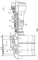
- FIG. 1 schematically illustrates a gas turbine engine 20.
- the gas turbine engine 20 is disclosed herein as a two-spool turbofan that generally incorporates a fan section 22, a compressor section 24, a combustor section 26 and a turbine section 28.
- Alternative engines might include other systems or features.
- the fan section 22 drives air along a bypass flow path B in a bypass duct, while the compressor section 24 drives air along a core flow path C for compression and communication into the combustor section 26 and then expansion through the turbine section 28.
- FIG. 1 schematically illustrates a gas turbine engine 20.
- the gas turbine engine 20 is disclosed herein as a two-spool turbofan that generally incorporates a fan section 22, a compressor section 24, a combustor section 26 and a turbine section 28.
- Alternative engines might include other systems or features.
- the fan section 22 drives air along a bypass flow path B in a bypass duct
- the compressor section 24 drives air along a core flow path C for compression and communication into the combustor section
- the exemplary gas turbine engine 20 generally includes a low speed spool 30 and a high speed spool 32 mounted for rotation about an engine central longitudinal axis A relative to an engine static structure 36 via several bearing systems 38. It should be understood that various bearing systems 38 at various locations may alternatively or additionally be provided, and the location of bearing systems 38 may be varied as appropriate to the application.
- the low speed spool 30 generally includes an inner shaft 40 that interconnects a fan 42, a low pressure compressor 44 and a low pressure turbine 46.
- the inner shaft 40 is connected to the fan 42 through a speed change mechanism, which in exemplary gas turbine engine 20 is illustrated as a geared architecture 48 to drive the fan 42 at a lower speed than the low speed spool 30.
- the high speed spool 32 includes an outer shaft 50 that interconnects a high pressure compressor 52 and high pressure turbine 54.
- a combustor 56 is arranged in the gas turbine engine 20 between the high pressure compressor 52 and the high pressure turbine 54.
- the engine static structure 36 is arranged generally between the high pressure turbine 54 and the low pressure turbine 46.
- the engine static structure 36 further supports the bearing systems 38 in the turbine section 28.
- the inner shaft 40 and the outer shaft 50 are concentric and rotate via bearing systems 38 about the engine central longitudinal axis A which is collinear with their longitudinal axes.
- the core airflow is compressed by the low pressure compressor 44 and then the high pressure compressor 52, is mixed and burned with fuel in the combustor 56 and is then expanded over the high pressure turbine 54 and the low pressure turbine 46.
- the high and low pressure turbines 54 and 46 rotationally drive the low speed spool 30 and the high speed spool 32, respectively, in response to the expansion.
- geared architecture 48 may be located aft of the combustor section 26 or even aft of the turbine section 28, and the fan section 22 may be positioned forward or aft of the location of geared architecture 48.
- the gas turbine engine 20 in one example is a high-bypass geared aircraft engine.
- the gas turbine engine 20 bypass ratio is greater than about six (6), with an example embodiment being greater than about ten (10)
- the geared architecture 48 is an epicyclic gear train, such as a planetary gear system or other gear system, with a gear reduction ratio of greater than about 2.3 and the low pressure turbine 46 has a pressure ratio that is greater than about five (5).
- the gas turbine engine 20 bypass ratio is greater than about ten (10:1)
- the fan diameter is significantly larger than that of the low pressure compressor 44
- the low pressure turbine 46 has a pressure ratio that is greater than about five (5:1).
- Low pressure turbine 46 pressure ratio is pressure measured prior to inlet of low pressure turbine 46 as related to the pressure at the outlet of the low pressure turbine 46 prior to an exhaust nozzle.
- the geared architecture 48 may be an epicycle gear train, such as a planetary gear system or other gear system, with a gear reduction ratio of greater than about 2.3:1. It should be understood, however, that the above parameters are only exemplary of one embodiment of a geared architecture engine and that the present disclosure is applicable to other gas turbine engines including direct drive turbofans.
- the fan section 22 of the gas turbine engine 20 is designed for a particular flight condition--typically cruise at about 0.8 Mach and about 35,000 feet (10,668 meters).
- 'TSFC' Thrust Specific Fuel Consumption
- Low fan pressure ratio is the pressure ratio across the fan blade alone, without a Fan Exit Guide Vane (“FEGV”) system.
- an impingement cooling approach for use in a rotating seal or another suitable component of a gas turbine engine, such as the gas turbine engine 20 of FIG. 1 .
- the impingement cooling approach is characterized in that oil is fed through an entrance channel to a plenum and from the plenum to an exit channel.
- the entrance channel can, in some cases, have a circular cross-section and is positioned between 30-60 degrees from the horizontal plane (i.e., the engine central longitudinal axis of the gas turbine engine 20 of FIG. 1 ).
- the plenum can be provided as a racetrack-shaped channel and can have a larger cross-sectional area than the entrance and exit channels.
- the plenum can be arranged to extend circumferentially through the rotating seal of the gas turbine engine 20 and across the stationary seal with which the rotating seal makes contact.
- a compartment 201 of the gas turbine engine 20 of FIG. 1 includes a forward stationary seal 210 that is stationary relative to a rotational axis, such as the engine centerline A (see FIG. 1 ), a forward rotating seal 220 that is rotatable about the rotational axis, an aft stationary seal 230 that is stationary relative to the rotational axis and an aft rotating seal 240 that is rotatable about the rotational axis.
- the forward stationary seal 210 faces in the aft direction and the forward rotating seal 220 faces in the forward direction and contacts with the forward stationary seal 210.
- the aft stationary seal 230 faces in the forward direction and the aft rotating seal 240 faces in the aft direction and contacts with the aft stationary seal 210.
- the following description will generally relate to the configuration of the aft rotating seal 240 and the contact between the aft rotating seal 240 and the aft stationary seal 230. This is done for clarity and brevity and should not be interpreted as limiting the scope of the disclosure in any way. It should be further understood that the features of the following description are applicable to both the aft rotating seal 240 and the contact between the aft rotating seal 240 and the aft stationary seal 230 as well as the forward rotating seal 220 and the contact between the forward rotating seal 220 and the forward stationary seal 210 as well.
- a conventional version of the aft rotating seal 240 has a cooling channel defined therein from an interior facing surface to an exterior facing surface such that, when the conventional aft rotating seal rotates about the engine centerline, cooling fluid (e.g., oil) is forced by centrifugal force to flow radially outwardly through the cooling channel.
- cooling fluid e.g., oil
- the cooling channel does not extend near where the conventional aft rotating seal 240 contacts the aft stationary seal 230.
- the portion of the conventional aft rotating seal 240 that makes frictional, heat generating contact with the aft stationary seal 230 during operations of the gas turbine engine 20 does not thermally interact with the cooling fluid in the cooling channel to a substantial degree.
- a hot-zone 301 can be generated in the portion of the conventional aft rotating seal 240. This hot-zone can lead to damage and wear of the aft rotating seal 240 as well as degraded performance of the gas turbine engine 20.
- an aft rotating seal 401 is provided for use in the gas turbine engine 20 of FIG. 1 and the compartment 201 of FIG. 2 and includes a body 410.
- the body 410 has a first surface 411, a second surface 412 and first and second additional surfaces 413 and 414.
- the first surface 411 is disposable to face the rotational axis or engine centerline A of FIG. 1 (hereinafter referred to as the "rotational axis").
- the second surface 412 is disposable to contact with a stationary element (hereinafter referred to as the "aft stationary seal 230" of FIG. 2 ).
- the first and second additional surfaces 413 and 414 are opposite the first surface 411 and the second surface 412, respectively.
- the body 410 is formed to define a cooling channel 420 that includes one or more entrance channels 430, one or more exit channels 440 and a plenum 450.
- Each of the one or more entrance channels 430 respectively extends from an inlet 431 coincident with the first surface 411 to an outlet 432 at an entrance to the plenum 450.
- Each of the one or more exit channels 440 respectively extends from an inlet 441 at an exit of the plenum 450 to an outlet 442 coincident with one of the first and second additional surfaces 413 and 414.
- the plenum 450 extends circumferentially through the body 410 and has a hot side 451 that is adjacent to the second surface 412 and a relatively cool side 452 that is opposite the hot side 451.
- the formation of the body 410 and the cooling channel 410 can be accomplished by additive manufacturing, three-dimensional (3D) printing or other similar procceses.
- the plenum 450 is fluidly interposed between the one or more entrance channels 430 and the one or more exit channels 440.
- cooling fluid e.g., oil
- centrifugal force is forced by centrifugal force to enter and flow through the one or more entrance channels 430 to the plenum 450, to impinge against at least the hot side 451 of the plenum 450 and to exit and then flow through the one or more exit channels 440.
- the cooling fluid moving through the one or more entrance channels 430 flows along radial outer surfaces 4301 of the one or more entrance channels 430 and is expelled in a jet-like flow from the outlets 432 to impinge against the hot side 451 of the plenum 450.
- the cooling fluid moves in a turbulent manner between the hot side 451 and the relatively cool side 452 before forming a film of cooling fluid and exiting into the one or more exit channels 440.
- the impingement of the cooling fluid against the hot side 451 and the subsequent turbulent flow causes the cooling fluid to efficiently thermally interact with the hot side 451 and thus to remove the heat generated by the frictional, heat generating contact between the second surface 412 and the aft stationary seal 430.
- the one or more entrance channels 430 and the one or more exit channels 440 can have circular cross-sections when viewed along the perspectives identified by lines 4-4 in FIG. 4 , the one or more entrance channels 430 can be angled at about -30-60 degrees from the rotational axis and are substantially straight along respective entire lengths thereof.
- the plenum 450 can have a racetrack-shaped cross-section when viewed along the circumferential perspective identified by line 5-5 in FIG. 4 .
- This racetrack-shaped cross-section can have a larger cross-sectional area than that of any of the one or more entrance channels 430 or any of the one or more exit channels 440 and provides for separation distance D between the hot side 451 and the relatively cool side 452, which encourages turbulent flow of the cooling fluid.
- the one or more entrance channels 430 can exhibit one or more turns or angles 501 or curves (which are depicted as the dashed lines) between the inlet 431 and the outlet 432. These turns or angles 501 or the curves can be disposed to cause cooling fluid to flow through an increased percentage of an interior of the body 410 or can increase or decrease the angle ⁇ at which the cooling fluid impinges against the hot side 451 of the plenum 450.
- the turns or angles 501 or the curves can be oriented counter-clockwise relative to the initial angling of the one or more entrance channels 430 as shown in FIG. 5 or can be oriented clockwise.
- the hot side 451 of the plenum 450 can include a protrusion surface portion 502 that protrudes toward the one or more entrance channels 430 and the relatively cool side 452.
- the protrusion surface portion 502 includes an impingement section 503 that is disposed to be impinged upon by the cooling fluid exiting the one of more entrance channels 430, a substantially flat section 504 and a curved section 505 that is radially interposed between the impingement section 503 and the substantially flat section 504.
- the protrusion surface portion 502 increases a turbulence of the flows of cooling fluid within the plenum 450 and thereby increases thermal communication from the second surface 412 to the cooling fluid.
- the aft rotating seal 401 can be ring-shaped when viewed along the perspective of the rotational axis and the plenum 450 can extend circumferentially through an entirety of the body 410. That is, the plenum 450 can be continuous along the circumferential dimension.
- the one or more entrance channels 430 can be oriented along the radial dimension R relative to the rotational axis and the one or more exit channels 440 can be angled relative to the radial dimension R. Regardless of the angling or lack thereof of the one or more entrance channels 230 and the one or more exit channels 440, the outlets 442 of one or more exit channels 440 can be coincident with the first additional surface 413 (see FIG. 4 ) or the second additional surface 414 (see FIGS. 6-8 ).
- numbers of the one or more entrance channels 430 and the one or more exit channels 440 can be the same or can vary relative to one another by design or application need (only one entrance channel 430 and only one exit channel 440 are shown in FIG. 6 for clarity).
- the variation in numbers of entrance channels 430 and exit channels 440 can be provided for optimization purposes, depending on cooling fluid distribution from a design perspective. That is, by having lesser exit channels 440 than entrance channels 430, for example, cooling fluid can be retained within the plenum 450 for longer residence times to allow for more heat removal.
- the outlets 432 of the one or more entrance channels 430 can be formed as flared outlets 901.
- a greater spread of the cooling fluid can impinge on an increased percentage of the hot side 451 of the plenum 450.
- the flared outlets 901 can be varied.
- Benefits of the features described herein are the provision of an impingement cooling approach that dissipates the heat generated between rotating and stationary seals that contact one another in a gas turbine engine.
- the impingement cooling provides a relatively high heat removal capability at hot zones as compared to conventional cooling approaches and disperses heat removed from the hot zones to neighboring zones by the formation of cooling oil films exiting the plenum.
Landscapes
- Engineering & Computer Science (AREA)
- General Engineering & Computer Science (AREA)
- Mechanical Engineering (AREA)
- Chemical & Material Sciences (AREA)
- Materials Engineering (AREA)
- Manufacturing & Machinery (AREA)
- Physics & Mathematics (AREA)
- Optics & Photonics (AREA)
- Turbine Rotor Nozzle Sealing (AREA)
Abstract
Description
- Exemplary embodiments of the present disclosure relate generally to gas turbine engines and, in one embodiment, to an impingement cooled rotating seal.
- In a gas turbine engine, air is compressed in a compressor and compressor air is then mixed with fuel and combusted in a combustor to produce a high-temperature and high-pressure working fluid. This working fluid is directed into a turbine in which the working fluid is expanded to generate power. The generated power drives the rotation of a rotor within the turbine through aerodynamic interactions between the working fluid and turbine blades or airfoils. The rotor can be used to drive rotations of a propeller or to produce electricity in a generator.
- The turbine or turbine section of the gas turbine engine has multiple rotating components and multiple stationary components and, in some cases, a rotating component contacts with a stationary component. This occurs, for example, with the rotating seal plate and the stationary seal of a turbine section and a significant amount of heat can be generated at the contact surface between the rotating seal and the stationary seal during operational conditions. Previously, this generated heat has been dissipated by the implementation of cooling channels within the rotating seal and the introduction of oil into the cooling channels as a coolant to remove the generated heat. The cooling channels are normally provided as compound angle cooling channels that are positioned as close as possible to hot spots in the rotating seal but the locations of these cooling channels are typically limited by conventional machining processes that are incapable of forming cooling channels in locations where the oil can fully achieve the desired cooling effect. This limits the overall cooling performance of the cooling channels.
- Accordingly, a need exists for an impingement cooling approach in a rotating seal that provides improved performance as compared to what is possible with conventional cooling channels.
- According to an aspect of the disclosure, a rotating seal rotatable about a rotational axis is provided. The rotating seal includes a body having a first surface disposable to face the rotational axis and a second surface disposable to contact with a stationary element. The body defines a cooling channel including one or more entrance channels respectively extending from the first surface, one or more exit channels and a plenum. The plenum extends circumferentially through the body and has a hot side adjacent to the second surface. The plenum is fluidly interposed between the one or more entrance channels and the one or more exit channels whereby fluid exiting the one or more entrance channels and entering the plenum impinges against the hot side.
- In accordance with additional or alternative embodiments, the first surface includes an axial surface disposable to face radially inwardly toward the rotational axis and the second surface is disposable to face axially toward the stationary element.
- In accordance with additional or alternative embodiments, the one or more entrance channels and the one or more exit channels have circular cross-sections.
- In accordance with additional or alternative embodiments, the one or more entrance channels are angled at about -30-60 degrees from the rotational axis.
- In accordance with additional or alternative embodiments, the plenum has a racetrack-shaped cross-section and a larger cross-sectional area than the one or more entrance channels and the one or more exit channels.
- In accordance with additional or alternative embodiments, the plenum includes a protrusion surface portion that protrudes toward the one or more entrance channels.
- In accordance with additional or alternative embodiments, the one or more entrance channels are oriented along a radial dimension relative to the rotational axis and the one or more exit channels are angled relative to the radial dimension.
- In accordance with additional or alternative embodiments, the one or more entrance channels have flared outlets.
- According to an aspect of the disclosure, a turbine section of a gas turbine engine having an engine centerline is provided and includes stationary and rotating seals, which are stationary and rotatable relative to the engine centerline, respectively. The rotating seal includes a body having a first surface disposable to face the engine centerline and a second surface disposable to contact with the stationary element. The body defines a cooling channel that includes one or more entrance channels respectively extending from the first surface, one or more exit channels and a plenum. The plenum extends circumferentially through the body and haves a hot side adjacent to the second surface. The plenum is fluidly interposed between the one or more entrance channels and the one or more exit channels whereby fluid exiting the one or more entrance channels and entering the plenum flows along outer surfaces of the one or more entrance channels and impinges against the hot side.
- In accordance with additional or alternative embodiments, the stationary and rotating seals face in the forward and aft directions, respectively, or the stationary and rotating seals face in the aft and forward directions, respectively, and the first surface includes an axial surface disposable to face radially inwardly toward the engine centerline and the second surface is disposable to face axially toward the stationary element.
- In accordance with additional or alternative embodiments, the one or more entrance channels and the one or more exit channels have circular cross-sections.
- In accordance with additional or alternative embodiments, the one or more entrance channels are angled at about -30-60 degrees from the engine centerline.
- In accordance with additional or alternative embodiments, the plenum has a racetrack-shaped cross-section and a larger cross-sectional area than the one or more entrance channels and the one or more exit channels.
- In accordance with additional or alternative embodiments, the plenum includes a protrusion surface portion that protrudes toward the one or more entrance channels.
- In accordance with additional or alternative embodiments, the one or more entrance channels are oriented along a radial dimension relative to the engine centerline and the one or more exit channels are angled relative to the radial dimension.
- In accordance with additional or alternative embodiments, the one or more entrance channels have flared outlets.
- According to an aspect of the disclosure, a method of additively manufacturing a rotating seal to be rotatable about a rotational axis is provided. The method includes additively manufacturing a body to have a first surface disposable to face the rotational axis and a second surface disposable to contact with a stationary element and to define a cooling channel. The cooling channel includes one or more entrance channels respectively extending from the first surface, one or more exit channels and a plenum. The plenum extends circumferentially through the body and has a hot side adjacent to the second surface. The plenum is fluidly interposed between the one or more entrance channels and the one or more exit channels whereby fluid exiting the one or more entrance channels and entering the plenum impinges against the hot side.
- In accordance with additional or alternative embodiments, the one or more entrance channels and the one or more exit channels have circular cross-sections and the one or more entrance channels are angled at about -30-60 degrees from the rotational axis. The plenum has a racetrack-shaped cross-section and a larger cross-sectional area than the one or more entrance channels and the one or more exit channels or the plenum includes a protrusion surface portion that protrudes toward the one or more entrance channels.
- In accordance with additional or alternative embodiments, the one or more entrance channels are oriented along a radial dimension relative to the rotational axis and the one or more exit channels are angled relative to the radial dimension.
- In accordance with additional or alternative embodiments, the one or more entrance channels have flared outlets.
- These and other advantages and features will become more apparent from the following description taken in conjunction with the drawings.
- The following descriptions should not be considered limiting in any way. With reference to the accompanying drawings, like elements are numbered alike:
-
FIG. 1 is a partial cross-sectional view of a gas turbine engine; -
FIG. 2 is a side view of a compartment of the gas turbine engine ofFIG. 1 ; -
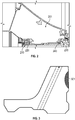
FIG. 3 is an illustration of a hot spot of a rotating seal of the compartment ofFIG. 2 ; -
FIG. 4 is schematic side view of a rotating seal with a cooling channel in accordance with embodiments; -
FIG. 5 is schematic side view of a rotating seal with a cooling channel in accordance with further embodiments; -
FIG. 6 is an axial view of the rotating seal ofFIG. 4 in accordance with embodiments; -
FIG. 7 is a perspective view of the rotating seal ofFIG. 4 in accordance with embodiments; -
FIG. 8 is a perspective view of the rotating seal ofFIG. 4 in accordance with embodiments; and -
FIG. 9 is a schematic side view of an outlet of an entrance channel of the rotating seal ofFIG. 4 in accordance with further embodiments. - These and other advantages and features will become more apparent from the following description taken in conjunction with the drawings.
- A detailed description of one or more embodiments of the disclosed apparatus and method are presented herein by way of exemplification and not limitation with reference to the Figures.
-
FIG. 1 schematically illustrates agas turbine engine 20. Thegas turbine engine 20 is disclosed herein as a two-spool turbofan that generally incorporates afan section 22, acompressor section 24, acombustor section 26 and aturbine section 28. Alternative engines might include other systems or features. Thefan section 22 drives air along a bypass flow path B in a bypass duct, while thecompressor section 24 drives air along a core flow path C for compression and communication into thecombustor section 26 and then expansion through theturbine section 28. Although depicted as a two-spool turbofan gas turbine engine in the disclosed non-limiting embodiment, it should be understood that the concepts described herein are not limited to use with two-spool turbofans and may be applied to other types of turbine engines including three-spool architectures. - The exemplary
gas turbine engine 20 generally includes alow speed spool 30 and ahigh speed spool 32 mounted for rotation about an engine central longitudinal axis A relative to an enginestatic structure 36 viaseveral bearing systems 38. It should be understood that various bearingsystems 38 at various locations may alternatively or additionally be provided, and the location of bearingsystems 38 may be varied as appropriate to the application. - The
low speed spool 30 generally includes aninner shaft 40 that interconnects afan 42, alow pressure compressor 44 and alow pressure turbine 46. Theinner shaft 40 is connected to thefan 42 through a speed change mechanism, which in exemplarygas turbine engine 20 is illustrated as a gearedarchitecture 48 to drive thefan 42 at a lower speed than thelow speed spool 30. Thehigh speed spool 32 includes anouter shaft 50 that interconnects ahigh pressure compressor 52 andhigh pressure turbine 54. Acombustor 56 is arranged in thegas turbine engine 20 between thehigh pressure compressor 52 and thehigh pressure turbine 54. The enginestatic structure 36 is arranged generally between thehigh pressure turbine 54 and thelow pressure turbine 46. The enginestatic structure 36 further supports the bearingsystems 38 in theturbine section 28. Theinner shaft 40 and theouter shaft 50 are concentric and rotate via bearingsystems 38 about the engine central longitudinal axis A which is collinear with their longitudinal axes. - The core airflow is compressed by the
low pressure compressor 44 and then thehigh pressure compressor 52, is mixed and burned with fuel in thecombustor 56 and is then expanded over thehigh pressure turbine 54 and thelow pressure turbine 46. The high andlow pressure turbines low speed spool 30 and thehigh speed spool 32, respectively, in response to the expansion. It will be appreciated that each of the positions of thefan section 22,compressor section 24,combustor section 26,turbine section 28, and fandrive gear system 48 may be varied. For example, gearedarchitecture 48 may be located aft of thecombustor section 26 or even aft of theturbine section 28, and thefan section 22 may be positioned forward or aft of the location of gearedarchitecture 48. - The
gas turbine engine 20 in one example is a high-bypass geared aircraft engine. In a further example, thegas turbine engine 20 bypass ratio is greater than about six (6), with an example embodiment being greater than about ten (10), the gearedarchitecture 48 is an epicyclic gear train, such as a planetary gear system or other gear system, with a gear reduction ratio of greater than about 2.3 and thelow pressure turbine 46 has a pressure ratio that is greater than about five (5). In one disclosed embodiment, thegas turbine engine 20 bypass ratio is greater than about ten (10:1), the fan diameter is significantly larger than that of thelow pressure compressor 44, and thelow pressure turbine 46 has a pressure ratio that is greater than about five (5:1).Low pressure turbine 46 pressure ratio is pressure measured prior to inlet oflow pressure turbine 46 as related to the pressure at the outlet of thelow pressure turbine 46 prior to an exhaust nozzle. The gearedarchitecture 48 may be an epicycle gear train, such as a planetary gear system or other gear system, with a gear reduction ratio of greater than about 2.3:1. It should be understood, however, that the above parameters are only exemplary of one embodiment of a geared architecture engine and that the present disclosure is applicable to other gas turbine engines including direct drive turbofans. - A significant amount of thrust is provided by the bypass flow B due to the high bypass ratio. The
fan section 22 of thegas turbine engine 20 is designed for a particular flight condition--typically cruise at about 0.8 Mach and about 35,000 feet (10,668 meters). The flight condition of 0.8 Mach and 35,000 ft (10,668 meters), with the engine at its best fuel consumption--also known as "bucket cruise Thrust Specific Fuel Consumption ('TSFC')"--is the industry standard parameter of lbm of fuel being burned divided by lbf of thrust the engine produces at that minimum point. "Low fan pressure ratio" is the pressure ratio across the fan blade alone, without a Fan Exit Guide Vane ("FEGV") system. - As will be described below, an impingement cooling approach for use in a rotating seal or another suitable component of a gas turbine engine, such as the
gas turbine engine 20 ofFIG. 1 , is provided. The impingement cooling approach is characterized in that oil is fed through an entrance channel to a plenum and from the plenum to an exit channel. The entrance channel can, in some cases, have a circular cross-section and is positioned between 30-60 degrees from the horizontal plane (i.e., the engine central longitudinal axis of thegas turbine engine 20 ofFIG. 1 ). The plenum can be provided as a racetrack-shaped channel and can have a larger cross-sectional area than the entrance and exit channels. The plenum can be arranged to extend circumferentially through the rotating seal of thegas turbine engine 20 and across the stationary seal with which the rotating seal makes contact. - With continued reference to
FIG. 1 and with additional reference toFIGS. 2 and 3 , acompartment 201 of thegas turbine engine 20 ofFIG. 1 includes a forwardstationary seal 210 that is stationary relative to a rotational axis, such as the engine centerline A (seeFIG. 1 ), a forwardrotating seal 220 that is rotatable about the rotational axis, an aftstationary seal 230 that is stationary relative to the rotational axis and an aftrotating seal 240 that is rotatable about the rotational axis. The forwardstationary seal 210 faces in the aft direction and the forwardrotating seal 220 faces in the forward direction and contacts with the forwardstationary seal 210. The aftstationary seal 230 faces in the forward direction and the aftrotating seal 240 faces in the aft direction and contacts with the aftstationary seal 210. - The following description will generally relate to the configuration of the aft
rotating seal 240 and the contact between the aftrotating seal 240 and the aftstationary seal 230. This is done for clarity and brevity and should not be interpreted as limiting the scope of the disclosure in any way. It should be further understood that the features of the following description are applicable to both the aftrotating seal 240 and the contact between the aftrotating seal 240 and the aftstationary seal 230 as well as the forwardrotating seal 220 and the contact between the forwardrotating seal 220 and the forwardstationary seal 210 as well. - As shown in
FIG. 3 , a conventional version of the aftrotating seal 240 has a cooling channel defined therein from an interior facing surface to an exterior facing surface such that, when the conventional aft rotating seal rotates about the engine centerline, cooling fluid (e.g., oil) is forced by centrifugal force to flow radially outwardly through the cooling channel. However, due to limits in manufacturing processes, the cooling channel does not extend near where the conventional aftrotating seal 240 contacts the aftstationary seal 230. Thus, the portion of the conventional aftrotating seal 240 that makes frictional, heat generating contact with the aftstationary seal 230 during operations of thegas turbine engine 20 does not thermally interact with the cooling fluid in the cooling channel to a substantial degree. Therefore, heat generated by the frictional, heat generating contact is not efficiently removed and a hot-zone 301 can be generated in the portion of the conventional aftrotating seal 240. This hot-zone can lead to damage and wear of the aftrotating seal 240 as well as degraded performance of thegas turbine engine 20. - With reference to
FIG. 4 , an aftrotating seal 401 is provided for use in thegas turbine engine 20 ofFIG. 1 and thecompartment 201 ofFIG. 2 and includes abody 410. Thebody 410 has afirst surface 411, asecond surface 412 and first and secondadditional surfaces first surface 411 is disposable to face the rotational axis or engine centerline A ofFIG. 1 (hereinafter referred to as the "rotational axis"). Thesecond surface 412 is disposable to contact with a stationary element (hereinafter referred to as the "aftstationary seal 230" ofFIG. 2 ). The first and secondadditional surfaces first surface 411 and thesecond surface 412, respectively. Thebody 410 is formed to define acooling channel 420 that includes one ormore entrance channels 430, one ormore exit channels 440 and aplenum 450. Each of the one ormore entrance channels 430 respectively extends from aninlet 431 coincident with thefirst surface 411 to anoutlet 432 at an entrance to theplenum 450. Each of the one ormore exit channels 440 respectively extends from aninlet 441 at an exit of theplenum 450 to anoutlet 442 coincident with one of the first and secondadditional surfaces plenum 450 extends circumferentially through thebody 410 and has ahot side 451 that is adjacent to thesecond surface 412 and a relativelycool side 452 that is opposite thehot side 451. - The formation of the
body 410 and thecooling channel 410 can be accomplished by additive manufacturing, three-dimensional (3D) printing or other similar procceses. - The
plenum 450 is fluidly interposed between the one ormore entrance channels 430 and the one ormore exit channels 440. During operations of thegas turbine engine 20 in which the aftrotating seal 401 rotates about the rotational axis, cooling fluid (e.g., oil) is forced by centrifugal force to enter and flow through the one ormore entrance channels 430 to theplenum 450, to impinge against at least thehot side 451 of theplenum 450 and to exit and then flow through the one ormore exit channels 440. In greater detail, the cooling fluid moving through the one ormore entrance channels 430 flows along radialouter surfaces 4301 of the one ormore entrance channels 430 and is expelled in a jet-like flow from theoutlets 432 to impinge against thehot side 451 of theplenum 450. Once the cooling fluid is inside theplenum 450, the cooling fluid moves in a turbulent manner between thehot side 451 and the relativelycool side 452 before forming a film of cooling fluid and exiting into the one ormore exit channels 440. The impingement of the cooling fluid against thehot side 451 and the subsequent turbulent flow causes the cooling fluid to efficiently thermally interact with thehot side 451 and thus to remove the heat generated by the frictional, heat generating contact between thesecond surface 412 and the aftstationary seal 430. - In accordance with embodiments, the one or
more entrance channels 430 and the one ormore exit channels 440 can have circular cross-sections when viewed along the perspectives identified by lines 4-4 inFIG. 4 , the one ormore entrance channels 430 can be angled at about -30-60 degrees from the rotational axis and are substantially straight along respective entire lengths thereof. In accordance with additional embodiments, theplenum 450 can have a racetrack-shaped cross-section when viewed along the circumferential perspective identified by line 5-5 inFIG. 4 . This racetrack-shaped cross-section can have a larger cross-sectional area than that of any of the one ormore entrance channels 430 or any of the one ormore exit channels 440 and provides for separation distance D between thehot side 451 and the relativelycool side 452, which encourages turbulent flow of the cooling fluid. - With reference to
FIG. 5 , alternative and further embodiments of the aftrotating seal 401 are provided. - For example, in accordance with alternative embodiments, the one or
more entrance channels 430 can exhibit one or more turns orangles 501 or curves (which are depicted as the dashed lines) between theinlet 431 and theoutlet 432. These turns orangles 501 or the curves can be disposed to cause cooling fluid to flow through an increased percentage of an interior of thebody 410 or can increase or decrease the angle α at which the cooling fluid impinges against thehot side 451 of theplenum 450. The turns orangles 501 or the curves can be oriented counter-clockwise relative to the initial angling of the one ormore entrance channels 430 as shown inFIG. 5 or can be oriented clockwise. - As another example, in accordance with further embodiments, the
hot side 451 of theplenum 450 can include aprotrusion surface portion 502 that protrudes toward the one ormore entrance channels 430 and the relativelycool side 452. Theprotrusion surface portion 502 includes animpingement section 503 that is disposed to be impinged upon by the cooling fluid exiting the one ofmore entrance channels 430, a substantiallyflat section 504 and acurved section 505 that is radially interposed between theimpingement section 503 and the substantiallyflat section 504. Theprotrusion surface portion 502 increases a turbulence of the flows of cooling fluid within theplenum 450 and thereby increases thermal communication from thesecond surface 412 to the cooling fluid. - The following description will relate to the embodiments shown in
FIG. 4 . This is done for purposes of clarity and brevity and it is to be understood that the following description is also applicable to the embodiments ofFIG. 5 as well. - With reference to
FIGS. 6-8 , the aftrotating seal 401 can be ring-shaped when viewed along the perspective of the rotational axis and theplenum 450 can extend circumferentially through an entirety of thebody 410. That is, theplenum 450 can be continuous along the circumferential dimension. - In addition, as shown in
FIGS. 6-8 , the one ormore entrance channels 430 can be oriented along the radial dimension R relative to the rotational axis and the one ormore exit channels 440 can be angled relative to the radial dimension R. Regardless of the angling or lack thereof of the one ormore entrance channels 230 and the one ormore exit channels 440, theoutlets 442 of one ormore exit channels 440 can be coincident with the first additional surface 413 (seeFIG. 4 ) or the second additional surface 414 (seeFIGS. 6-8 ). In addition, numbers of the one ormore entrance channels 430 and the one ormore exit channels 440 can be the same or can vary relative to one another by design or application need (only oneentrance channel 430 and only oneexit channel 440 are shown inFIG. 6 for clarity). In particular, the variation in numbers ofentrance channels 430 and exitchannels 440 can be provided for optimization purposes, depending on cooling fluid distribution from a design perspective. That is, by havinglesser exit channels 440 thanentrance channels 430, for example, cooling fluid can be retained within theplenum 450 for longer residence times to allow for more heat removal. - With reference to
FIG. 9 and in accordance with further embodiments, theoutlets 432 of the one ormore entrance channels 430 can be formed as flaredoutlets 901. In such cases, a greater spread of the cooling fluid can impinge on an increased percentage of thehot side 451 of theplenum 450. Here, while an overall velocity of the sprayed cooling fluid can be reduced by the flaredoutlets 901, the increased coverage of thehot side 451 can result in more uniform cooling. A shape and geometry of the flaredoutlets 901 can be varied. - Benefits of the features described herein are the provision of an impingement cooling approach that dissipates the heat generated between rotating and stationary seals that contact one another in a gas turbine engine. The impingement cooling provides a relatively high heat removal capability at hot zones as compared to conventional cooling approaches and disperses heat removed from the hot zones to neighboring zones by the formation of cooling oil films exiting the plenum.
- The term "about" is intended to include the degree of error associated with measurement of the particular quantity based upon the equipment available at the time of filing the application.
- The terminology used herein is for the purpose of describing particular embodiments only and is not intended to be limiting of the present disclosure. As used herein, the singular forms "a", "an" and "the" are intended to include the plural forms as well, unless the context clearly indicates otherwise. It will be further understood that the terms "comprises" and/or "comprising," when used in this specification, specify the presence of stated features, integers, steps, operations, elements, and/or components, but do not preclude the presence or addition of one or more other features, integers, steps, operations, element components, and/or groups thereof.
- While the present disclosure has been described with reference to an exemplary embodiment or embodiments, it will be understood by those skilled in the art that various changes may be made and equivalents may be substituted for elements thereof without departing from the scope of the present disclosure. In addition, many modifications may be made to adapt a particular situation or material to the teachings of the present disclosure without departing from the scope thereof. Therefore, it is intended that the present disclosure not be limited to the particular embodiment disclosed as the best mode contemplated for carrying out this present disclosure, but that the present disclosure will include all embodiments falling within the scope of the claims.
Claims (14)
- A rotating seal (401) rotatable about a rotational axis (A) and comprising:a body (410) having a first surface (411) disposable to face the rotational axis (A) and a second surface (412) disposable to contact with a stationary element (230),the body (410) defining a cooling channel (420) comprising:one or more entrance channels (430) respectively extending from the first surface (411);one or more exit channels (440); anda plenum (450) extending circumferentially through the body (410) and having a hot side (451) adjacent to the second surface (412),the plenum (450) being fluidly interposed between the one or more entrance channels (430) and the one or more exit channels (440) whereby fluid exiting the one or more entrance channels (430) and entering the plenum (450) impinges against the hot side (451).
- The rotating seal (401) according to claim 1, wherein the first surface (411) comprises an axial surface disposable to face radially inwardly toward the rotational axis (A) and the second surface (412) is disposable to face axially toward the stationary element (230).
- The rotating seal (401) according to claim 1 or 2, wherein the one or more entrance channels (430) and the one or more exit channels (440) have circular cross-sections.
- The rotating seal (401) according to claim 1, 2 or 3 wherein the one or more entrance channels (430) are angled at about -30-60 degrees from the rotational axis (A).
- The rotating seal (401) according to any preceding claim, wherein the plenum (450) has a racetrack-shaped cross-section and a larger cross-sectional area than the one or more entrance channels (430) and the one or more exit channels (440).
- The rotating seal (401) according to any of claims 1 to 4, wherein the plenum (450) comprises a protrusion surface portion (502) that protrudes toward the one or more entrance channels (430).
- The rotating seal (430) according to any preceding claim, wherein the one or more entrance channels (430) are oriented along a radial dimension (R) relative to the rotational axis (A) and the one or more exit channels (440) are angled relative to the radial dimension (R).
- The rotating seal (440) according to any preceding claim, wherein the one or more entrance channels (430) have flared outlets (432).
- A turbine section (28) of a gas turbine engine (20) having an engine centerline (A), the turbine section (28) comprising:stationary and rotating seals (230, 401), which are stationary and rotatable relative to the engine centerline (A), respectively;wherein the rotating seal (401) is the rotating seal (401) of any preceding claim; andwherein the fluid exiting the one or more entrance channels and entering the plenum (450) flows along outer surfaces (4301) of the one or more entrance channels (430).
- The turbine section (28) according to claim 9 when dependent on claim 2, wherein:
the stationary and rotating seals (230, 401) face in the forward and aft directions, respectively, or the stationary and rotating seals (230, 401) face in the aft and forward directions, respectively. - A method of additively manufacturing a rotating seal (401) to be rotatable about a rotational axis (A), the method comprising:
additively manufacturing a body (410) to have a first surface (411) disposable to face the rotational axis (A) and a second surface (412) disposable to contact with a stationary element (230) and to define a cooling channel (420) comprising:one or more entrance channels (430) respectively extending from the first surface (411);one or more exit channels (440); anda plenum (450) extending circumferentially through the body (410) and having a hot side (451) adjacent to the second surface (412),the plenum (450) being fluidly interposed between the one or more entrance channels (430) and the one or more exit channels (440) whereby fluid exiting the one or more entrance channels (430) and entering the plenum (450) impinges against the hot side (451). - The method according to claim 11, wherein:the one or more entrance channels (430) and the one or more exit channels (440) have circular cross-sections, andthe one or more entrance channels (430) are angled at about ∼30-60 degrees from the rotational axis (A),wherein:the plenum (450) has a racetrack-shaped cross-section and a larger cross-sectional area than the one or more entrance channels (430) and the one or more exit channels (440), orthe plenum (450) comprises a protrusion surface portion (502) that protrudes toward the one or more entrance channels (430).
- The method according to claim 11 or 12, wherein the one or more entrance channels (430) are oriented along a radial dimension (R) relative to the rotational axis (A) and the one or more exit channels (440) are angled relative to the radial dimension (R).
- The method according to claim 11, 12 or 13 wherein the one or more entrance channels (430) have flared outlets (432).
Applications Claiming Priority (1)
| Application Number | Priority Date | Filing Date | Title |
|---|---|---|---|
| US16/789,977 US11441448B2 (en) | 2020-02-13 | 2020-02-13 | Impingement cooled rotating seal |
Publications (2)
| Publication Number | Publication Date |
|---|---|
| EP3865680A1 true EP3865680A1 (en) | 2021-08-18 |
| EP3865680B1 EP3865680B1 (en) | 2024-05-08 |
Family
ID=74595235
Family Applications (1)
| Application Number | Title | Priority Date | Filing Date |
|---|---|---|---|
| EP21156971.0A Active EP3865680B1 (en) | 2020-02-13 | 2021-02-12 | Impingement cooled rotating seal |
Country Status (2)
| Country | Link |
|---|---|
| US (1) | US11441448B2 (en) |
| EP (1) | EP3865680B1 (en) |
Families Citing this family (1)
| Publication number | Priority date | Publication date | Assignee | Title |
|---|---|---|---|---|
| IT201800010391A1 (en) * | 2018-11-16 | 2020-05-16 | Nuovo Pignone Tecnologie Srl | PRE-MIXER FOR USE WITH CROSS-MOVING PISTON RODS AND RELATIVE MANUFACTURING METHOD |
Citations (12)
| Publication number | Priority date | Publication date | Assignee | Title |
|---|---|---|---|---|
| US2857182A (en) * | 1955-05-31 | 1958-10-21 | Gen Motors Corp | Shaft seal |
| US3578343A (en) * | 1969-04-24 | 1971-05-11 | Koppers Co Inc | Annular shoulder assembly for a rotating seal |
| DE202010003158U1 (en) * | 2010-03-04 | 2010-06-02 | Eagleburgmann Germany Gmbh & Co. Kg | Mechanical seal with integrated flushing device |
| US20140119887A1 (en) * | 2012-11-01 | 2014-05-01 | United Technologies Corporation | Fluid-cooled seal arrangement for a gas turbine engine |
| US20160273657A1 (en) * | 2013-11-06 | 2016-09-22 | United Technologies Corporation | Axial scoop seal plate |
| EP3282153A1 (en) * | 2016-08-09 | 2018-02-14 | United Technologies Corporation | Hydrodynamic seal seat cooling features |
| EP3382240A1 (en) * | 2017-03-28 | 2018-10-03 | United Technologies Corporation | Seal element with internal lubricant plenum for rotational equipment |
| US10174629B1 (en) * | 2017-09-11 | 2019-01-08 | United Technologies Corporation | Phonic seal seat |
| EP3495617A1 (en) * | 2017-12-05 | 2019-06-12 | United Technologies Corporation | Airfoil with internal cooling passages |
| EP3626936A2 (en) * | 2018-09-21 | 2020-03-25 | United Technologies Corporation | Hybrid wet-dry face seal seat |
| EP3647634A1 (en) * | 2018-10-29 | 2020-05-06 | United Technologies Corporation | Oil-cooled carbon seal |
| EP3702586A1 (en) * | 2019-02-26 | 2020-09-02 | United Technologies Corporation | Gas turbine engine including seal plate providing increased cooling adjacent contact area |
Family Cites Families (8)
| Publication number | Priority date | Publication date | Assignee | Title |
|---|---|---|---|---|
| US4928978A (en) * | 1988-04-07 | 1990-05-29 | United Technologies Corporation | Rotating shaft seal |
| US4990054A (en) * | 1989-12-13 | 1991-02-05 | Westinghouse Electric Corp. | Device incorporating micro-porous membrane for venting gases from seal assembly of a reactor coolant pump |
| JP3555683B2 (en) * | 1992-08-11 | 2004-08-18 | ユナイテッド・テクノロジーズ・コーポレイション | Seal assembly for rotating machine |
| EP1793144A1 (en) * | 2005-12-05 | 2007-06-06 | Jean Frédéric Melchior | Piston-sealing device for alternative internal combustion fitter or alternative compressor, and system comprising such a piston |
| SG10201708489UA (en) | 2012-11-20 | 2017-11-29 | New Way Machine Components Inc | Air bearing for use as seal |
| US9631508B2 (en) | 2013-06-13 | 2017-04-25 | Pratt & Whitney Canada Corp. | Internally cooled seal runner |
| US9909438B2 (en) * | 2016-04-12 | 2018-03-06 | United Technologies Corporation | Hydrodynamic carbon face seal pressure booster |
| US10494941B2 (en) | 2016-10-17 | 2019-12-03 | United Technologies Corporation | Seal face plate cooling |
-
2020
- 2020-02-13 US US16/789,977 patent/US11441448B2/en active Active
-
2021
- 2021-02-12 EP EP21156971.0A patent/EP3865680B1/en active Active
Patent Citations (12)
| Publication number | Priority date | Publication date | Assignee | Title |
|---|---|---|---|---|
| US2857182A (en) * | 1955-05-31 | 1958-10-21 | Gen Motors Corp | Shaft seal |
| US3578343A (en) * | 1969-04-24 | 1971-05-11 | Koppers Co Inc | Annular shoulder assembly for a rotating seal |
| DE202010003158U1 (en) * | 2010-03-04 | 2010-06-02 | Eagleburgmann Germany Gmbh & Co. Kg | Mechanical seal with integrated flushing device |
| US20140119887A1 (en) * | 2012-11-01 | 2014-05-01 | United Technologies Corporation | Fluid-cooled seal arrangement for a gas turbine engine |
| US20160273657A1 (en) * | 2013-11-06 | 2016-09-22 | United Technologies Corporation | Axial scoop seal plate |
| EP3282153A1 (en) * | 2016-08-09 | 2018-02-14 | United Technologies Corporation | Hydrodynamic seal seat cooling features |
| EP3382240A1 (en) * | 2017-03-28 | 2018-10-03 | United Technologies Corporation | Seal element with internal lubricant plenum for rotational equipment |
| US10174629B1 (en) * | 2017-09-11 | 2019-01-08 | United Technologies Corporation | Phonic seal seat |
| EP3495617A1 (en) * | 2017-12-05 | 2019-06-12 | United Technologies Corporation | Airfoil with internal cooling passages |
| EP3626936A2 (en) * | 2018-09-21 | 2020-03-25 | United Technologies Corporation | Hybrid wet-dry face seal seat |
| EP3647634A1 (en) * | 2018-10-29 | 2020-05-06 | United Technologies Corporation | Oil-cooled carbon seal |
| EP3702586A1 (en) * | 2019-02-26 | 2020-09-02 | United Technologies Corporation | Gas turbine engine including seal plate providing increased cooling adjacent contact area |
Also Published As
| Publication number | Publication date |
|---|---|
| US11441448B2 (en) | 2022-09-13 |
| EP3865680B1 (en) | 2024-05-08 |
| US20210254502A1 (en) | 2021-08-19 |
Similar Documents
| Publication | Publication Date | Title |
|---|---|---|
| EP3054113B1 (en) | Impingement cooled component and corresponding method for cooling a component | |
| US11407065B2 (en) | Systems and methods for manufacturing film cooling hole diffuser portion | |
| US20030223856A1 (en) | Gas turbine and method of bleeding gas therefrom | |
| EP3734019B1 (en) | Labyrinth seal with passive check valve | |
| US10544803B2 (en) | Method and system for cooling fluid distribution | |
| EP3702586B1 (en) | Gas turbine engine including seal plate providing increased cooling adjacent contact area | |
| WO2012146481A1 (en) | Casing cooling duct | |
| EP3246523B1 (en) | Cooled blade outer air seal | |
| US20190154050A1 (en) | Rotor hub seal | |
| EP3354853B1 (en) | Turbine blade with slot film cooling and manufacturing method | |
| EP3514331A1 (en) | Cooled airfoil and corresponding gas turbine engine | |
| EP3561229B1 (en) | Gas turbine engine component with platform cover plate | |
| CN115250037A (en) | Embedded Motor Cooling | |
| EP3865680B1 (en) | Impingement cooled rotating seal | |
| EP3392457B1 (en) | Turbine with upstream facing tangential onboard injector | |
| EP3663517B1 (en) | Component for a gas turbine engine and corresponding gas turbine engine | |
| EP3783203B1 (en) | Gas turbine engine component comprising a radial seal arrangement with axially elongated oil cooled runner | |
| US12215601B2 (en) | Air foil with staggered cooling hole configuration | |
| EP3712471B1 (en) | Two-piece seat for contacting seal | |
| EP3581762B1 (en) | Platform cooling arrangement for a gas turbine engine | |
| US20200182085A1 (en) | Impingement cooling of components | |
| CN117988936A (en) | Rotating machine seal having a wear protection assembly with an abradable cover |
Legal Events
| Date | Code | Title | Description |
|---|---|---|---|
| PUAI | Public reference made under article 153(3) epc to a published international application that has entered the european phase |
Free format text: ORIGINAL CODE: 0009012 |
|
| STAA | Information on the status of an ep patent application or granted ep patent |
Free format text: STATUS: THE APPLICATION HAS BEEN PUBLISHED |
|
| AK | Designated contracting states |
Kind code of ref document: A1 Designated state(s): AL AT BE BG CH CY CZ DE DK EE ES FI FR GB GR HR HU IE IS IT LI LT LU LV MC MK MT NL NO PL PT RO RS SE SI SK SM TR |
|
| STAA | Information on the status of an ep patent application or granted ep patent |
Free format text: STATUS: REQUEST FOR EXAMINATION WAS MADE |
|
| 17P | Request for examination filed |
Effective date: 20220218 |
|
| RBV | Designated contracting states (corrected) |
Designated state(s): AL AT BE BG CH CY CZ DE DK EE ES FI FR GB GR HR HU IE IS IT LI LT LU LV MC MK MT NL NO PL PT RO RS SE SI SK SM TR |
|
| STAA | Information on the status of an ep patent application or granted ep patent |
Free format text: STATUS: EXAMINATION IS IN PROGRESS |
|
| 17Q | First examination report despatched |
Effective date: 20230629 |
|
| RAP3 | Party data changed (applicant data changed or rights of an application transferred) |
Owner name: RTX CORPORATION |
|
| GRAP | Despatch of communication of intention to grant a patent |
Free format text: ORIGINAL CODE: EPIDOSNIGR1 |
|
| STAA | Information on the status of an ep patent application or granted ep patent |
Free format text: STATUS: GRANT OF PATENT IS INTENDED |
|
| INTG | Intention to grant announced |
Effective date: 20231201 |
|
| GRAS | Grant fee paid |
Free format text: ORIGINAL CODE: EPIDOSNIGR3 |
|
| GRAA | (expected) grant |
Free format text: ORIGINAL CODE: 0009210 |
|
| STAA | Information on the status of an ep patent application or granted ep patent |
Free format text: STATUS: THE PATENT HAS BEEN GRANTED |
|
| AK | Designated contracting states |
Kind code of ref document: B1 Designated state(s): AL AT BE BG CH CY CZ DE DK EE ES FI FR GB GR HR HU IE IS IT LI LT LU LV MC MK MT NL NO PL PT RO RS SE SI SK SM TR |
|
| REG | Reference to a national code |
Ref country code: GB Ref legal event code: FG4D |
|
| REG | Reference to a national code |
Ref country code: CH Ref legal event code: EP |
|
| REG | Reference to a national code |
Ref country code: DE Ref legal event code: R096 Ref document number: 602021012909 Country of ref document: DE |
|
| REG | Reference to a national code |
Ref country code: IE Ref legal event code: FG4D |
|
| REG | Reference to a national code |
Ref country code: LT Ref legal event code: MG9D |
|
| REG | Reference to a national code |
Ref country code: NL Ref legal event code: MP Effective date: 20240508 |
|
| PG25 | Lapsed in a contracting state [announced via postgrant information from national office to epo] |
Ref country code: IS Free format text: LAPSE BECAUSE OF FAILURE TO SUBMIT A TRANSLATION OF THE DESCRIPTION OR TO PAY THE FEE WITHIN THE PRESCRIBED TIME-LIMIT Effective date: 20240908 |
|
| PG25 | Lapsed in a contracting state [announced via postgrant information from national office to epo] |
Ref country code: BG Free format text: LAPSE BECAUSE OF FAILURE TO SUBMIT A TRANSLATION OF THE DESCRIPTION OR TO PAY THE FEE WITHIN THE PRESCRIBED TIME-LIMIT Effective date: 20240508 |
|
| PG25 | Lapsed in a contracting state [announced via postgrant information from national office to epo] |
Ref country code: FI Free format text: LAPSE BECAUSE OF FAILURE TO SUBMIT A TRANSLATION OF THE DESCRIPTION OR TO PAY THE FEE WITHIN THE PRESCRIBED TIME-LIMIT Effective date: 20240508 Ref country code: HR Free format text: LAPSE BECAUSE OF FAILURE TO SUBMIT A TRANSLATION OF THE DESCRIPTION OR TO PAY THE FEE WITHIN THE PRESCRIBED TIME-LIMIT Effective date: 20240508 |
|
| PG25 | Lapsed in a contracting state [announced via postgrant information from national office to epo] |
Ref country code: GR Free format text: LAPSE BECAUSE OF FAILURE TO SUBMIT A TRANSLATION OF THE DESCRIPTION OR TO PAY THE FEE WITHIN THE PRESCRIBED TIME-LIMIT Effective date: 20240809 |
|
| PG25 | Lapsed in a contracting state [announced via postgrant information from national office to epo] |
Ref country code: PT Free format text: LAPSE BECAUSE OF FAILURE TO SUBMIT A TRANSLATION OF THE DESCRIPTION OR TO PAY THE FEE WITHIN THE PRESCRIBED TIME-LIMIT Effective date: 20240909 |
|
| REG | Reference to a national code |
Ref country code: AT Ref legal event code: MK05 Ref document number: 1685154 Country of ref document: AT Kind code of ref document: T Effective date: 20240508 |
|
| PG25 | Lapsed in a contracting state [announced via postgrant information from national office to epo] |
Ref country code: NL Free format text: LAPSE BECAUSE OF FAILURE TO SUBMIT A TRANSLATION OF THE DESCRIPTION OR TO PAY THE FEE WITHIN THE PRESCRIBED TIME-LIMIT Effective date: 20240508 |
|
| PG25 | Lapsed in a contracting state [announced via postgrant information from national office to epo] |
Ref country code: ES Free format text: LAPSE BECAUSE OF FAILURE TO SUBMIT A TRANSLATION OF THE DESCRIPTION OR TO PAY THE FEE WITHIN THE PRESCRIBED TIME-LIMIT Effective date: 20240508 |
|
| PG25 | Lapsed in a contracting state [announced via postgrant information from national office to epo] |
Ref country code: AT Free format text: LAPSE BECAUSE OF FAILURE TO SUBMIT A TRANSLATION OF THE DESCRIPTION OR TO PAY THE FEE WITHIN THE PRESCRIBED TIME-LIMIT Effective date: 20240508 |
|
| PG25 | Lapsed in a contracting state [announced via postgrant information from national office to epo] |
Ref country code: PL Free format text: LAPSE BECAUSE OF FAILURE TO SUBMIT A TRANSLATION OF THE DESCRIPTION OR TO PAY THE FEE WITHIN THE PRESCRIBED TIME-LIMIT Effective date: 20240508 |
|
| PG25 | Lapsed in a contracting state [announced via postgrant information from national office to epo] |
Ref country code: LV Free format text: LAPSE BECAUSE OF FAILURE TO SUBMIT A TRANSLATION OF THE DESCRIPTION OR TO PAY THE FEE WITHIN THE PRESCRIBED TIME-LIMIT Effective date: 20240508 |
|
| PG25 | Lapsed in a contracting state [announced via postgrant information from national office to epo] |
Ref country code: PT Free format text: LAPSE BECAUSE OF FAILURE TO SUBMIT A TRANSLATION OF THE DESCRIPTION OR TO PAY THE FEE WITHIN THE PRESCRIBED TIME-LIMIT Effective date: 20240909 Ref country code: PL Free format text: LAPSE BECAUSE OF FAILURE TO SUBMIT A TRANSLATION OF THE DESCRIPTION OR TO PAY THE FEE WITHIN THE PRESCRIBED TIME-LIMIT Effective date: 20240508 Ref country code: NO Free format text: LAPSE BECAUSE OF FAILURE TO SUBMIT A TRANSLATION OF THE DESCRIPTION OR TO PAY THE FEE WITHIN THE PRESCRIBED TIME-LIMIT Effective date: 20240808 Ref country code: NL Free format text: LAPSE BECAUSE OF FAILURE TO SUBMIT A TRANSLATION OF THE DESCRIPTION OR TO PAY THE FEE WITHIN THE PRESCRIBED TIME-LIMIT Effective date: 20240508 Ref country code: LV Free format text: LAPSE BECAUSE OF FAILURE TO SUBMIT A TRANSLATION OF THE DESCRIPTION OR TO PAY THE FEE WITHIN THE PRESCRIBED TIME-LIMIT Effective date: 20240508 Ref country code: IS Free format text: LAPSE BECAUSE OF FAILURE TO SUBMIT A TRANSLATION OF THE DESCRIPTION OR TO PAY THE FEE WITHIN THE PRESCRIBED TIME-LIMIT Effective date: 20240908 Ref country code: HR Free format text: LAPSE BECAUSE OF FAILURE TO SUBMIT A TRANSLATION OF THE DESCRIPTION OR TO PAY THE FEE WITHIN THE PRESCRIBED TIME-LIMIT Effective date: 20240508 Ref country code: GR Free format text: LAPSE BECAUSE OF FAILURE TO SUBMIT A TRANSLATION OF THE DESCRIPTION OR TO PAY THE FEE WITHIN THE PRESCRIBED TIME-LIMIT Effective date: 20240809 Ref country code: FI Free format text: LAPSE BECAUSE OF FAILURE TO SUBMIT A TRANSLATION OF THE DESCRIPTION OR TO PAY THE FEE WITHIN THE PRESCRIBED TIME-LIMIT Effective date: 20240508 Ref country code: ES Free format text: LAPSE BECAUSE OF FAILURE TO SUBMIT A TRANSLATION OF THE DESCRIPTION OR TO PAY THE FEE WITHIN THE PRESCRIBED TIME-LIMIT Effective date: 20240508 Ref country code: BG Free format text: LAPSE BECAUSE OF FAILURE TO SUBMIT A TRANSLATION OF THE DESCRIPTION OR TO PAY THE FEE WITHIN THE PRESCRIBED TIME-LIMIT Effective date: 20240508 Ref country code: AT Free format text: LAPSE BECAUSE OF FAILURE TO SUBMIT A TRANSLATION OF THE DESCRIPTION OR TO PAY THE FEE WITHIN THE PRESCRIBED TIME-LIMIT Effective date: 20240508 Ref country code: RS Free format text: LAPSE BECAUSE OF FAILURE TO SUBMIT A TRANSLATION OF THE DESCRIPTION OR TO PAY THE FEE WITHIN THE PRESCRIBED TIME-LIMIT Effective date: 20240808 |
|
| PG25 | Lapsed in a contracting state [announced via postgrant information from national office to epo] |
Ref country code: DK Free format text: LAPSE BECAUSE OF FAILURE TO SUBMIT A TRANSLATION OF THE DESCRIPTION OR TO PAY THE FEE WITHIN THE PRESCRIBED TIME-LIMIT Effective date: 20240508 |
|
| PG25 | Lapsed in a contracting state [announced via postgrant information from national office to epo] |
Ref country code: EE Free format text: LAPSE BECAUSE OF FAILURE TO SUBMIT A TRANSLATION OF THE DESCRIPTION OR TO PAY THE FEE WITHIN THE PRESCRIBED TIME-LIMIT Effective date: 20240508 |
|
| PG25 | Lapsed in a contracting state [announced via postgrant information from national office to epo] |
Ref country code: CZ Free format text: LAPSE BECAUSE OF FAILURE TO SUBMIT A TRANSLATION OF THE DESCRIPTION OR TO PAY THE FEE WITHIN THE PRESCRIBED TIME-LIMIT Effective date: 20240508 |
|
| PG25 | Lapsed in a contracting state [announced via postgrant information from national office to epo] |
Ref country code: SK Free format text: LAPSE BECAUSE OF FAILURE TO SUBMIT A TRANSLATION OF THE DESCRIPTION OR TO PAY THE FEE WITHIN THE PRESCRIBED TIME-LIMIT Effective date: 20240508 Ref country code: RO Free format text: LAPSE BECAUSE OF FAILURE TO SUBMIT A TRANSLATION OF THE DESCRIPTION OR TO PAY THE FEE WITHIN THE PRESCRIBED TIME-LIMIT Effective date: 20240508 |
|
| PG25 | Lapsed in a contracting state [announced via postgrant information from national office to epo] |
Ref country code: SM Free format text: LAPSE BECAUSE OF FAILURE TO SUBMIT A TRANSLATION OF THE DESCRIPTION OR TO PAY THE FEE WITHIN THE PRESCRIBED TIME-LIMIT Effective date: 20240508 |
|
| PG25 | Lapsed in a contracting state [announced via postgrant information from national office to epo] |
Ref country code: SM Free format text: LAPSE BECAUSE OF FAILURE TO SUBMIT A TRANSLATION OF THE DESCRIPTION OR TO PAY THE FEE WITHIN THE PRESCRIBED TIME-LIMIT Effective date: 20240508 Ref country code: SK Free format text: LAPSE BECAUSE OF FAILURE TO SUBMIT A TRANSLATION OF THE DESCRIPTION OR TO PAY THE FEE WITHIN THE PRESCRIBED TIME-LIMIT Effective date: 20240508 Ref country code: RO Free format text: LAPSE BECAUSE OF FAILURE TO SUBMIT A TRANSLATION OF THE DESCRIPTION OR TO PAY THE FEE WITHIN THE PRESCRIBED TIME-LIMIT Effective date: 20240508 Ref country code: EE Free format text: LAPSE BECAUSE OF FAILURE TO SUBMIT A TRANSLATION OF THE DESCRIPTION OR TO PAY THE FEE WITHIN THE PRESCRIBED TIME-LIMIT Effective date: 20240508 Ref country code: DK Free format text: LAPSE BECAUSE OF FAILURE TO SUBMIT A TRANSLATION OF THE DESCRIPTION OR TO PAY THE FEE WITHIN THE PRESCRIBED TIME-LIMIT Effective date: 20240508 Ref country code: CZ Free format text: LAPSE BECAUSE OF FAILURE TO SUBMIT A TRANSLATION OF THE DESCRIPTION OR TO PAY THE FEE WITHIN THE PRESCRIBED TIME-LIMIT Effective date: 20240508 |
|
| PG25 | Lapsed in a contracting state [announced via postgrant information from national office to epo] |
Ref country code: IT Free format text: LAPSE BECAUSE OF FAILURE TO SUBMIT A TRANSLATION OF THE DESCRIPTION OR TO PAY THE FEE WITHIN THE PRESCRIBED TIME-LIMIT Effective date: 20240508 |
|
| REG | Reference to a national code |
Ref country code: DE Ref legal event code: R097 Ref document number: 602021012909 Country of ref document: DE |
|
| PLBE | No opposition filed within time limit |
Free format text: ORIGINAL CODE: 0009261 |
|
| STAA | Information on the status of an ep patent application or granted ep patent |
Free format text: STATUS: NO OPPOSITION FILED WITHIN TIME LIMIT |
|
| 26N | No opposition filed |
Effective date: 20250211 |
|
| PG25 | Lapsed in a contracting state [announced via postgrant information from national office to epo] |
Ref country code: SI Free format text: LAPSE BECAUSE OF FAILURE TO SUBMIT A TRANSLATION OF THE DESCRIPTION OR TO PAY THE FEE WITHIN THE PRESCRIBED TIME-LIMIT Effective date: 20240508 |
|
| PG25 | Lapsed in a contracting state [announced via postgrant information from national office to epo] |
Ref country code: SE Free format text: LAPSE BECAUSE OF FAILURE TO SUBMIT A TRANSLATION OF THE DESCRIPTION OR TO PAY THE FEE WITHIN THE PRESCRIBED TIME-LIMIT Effective date: 20240508 |
|
| PG25 | Lapsed in a contracting state [announced via postgrant information from national office to epo] |
Ref country code: MC Free format text: LAPSE BECAUSE OF FAILURE TO SUBMIT A TRANSLATION OF THE DESCRIPTION OR TO PAY THE FEE WITHIN THE PRESCRIBED TIME-LIMIT Effective date: 20240508 |
|
| REG | Reference to a national code |
Ref country code: CH Ref legal event code: PL |
|
| PG25 | Lapsed in a contracting state [announced via postgrant information from national office to epo] |
Ref country code: LU Free format text: LAPSE BECAUSE OF NON-PAYMENT OF DUE FEES Effective date: 20250212 |
|
| PG25 | Lapsed in a contracting state [announced via postgrant information from national office to epo] |
Ref country code: CH Free format text: LAPSE BECAUSE OF NON-PAYMENT OF DUE FEES Effective date: 20250228 |
|
| REG | Reference to a national code |
Ref country code: BE Ref legal event code: MM Effective date: 20250228 |
|
| PG25 | Lapsed in a contracting state [announced via postgrant information from national office to epo] |
Ref country code: BE Free format text: LAPSE BECAUSE OF NON-PAYMENT OF DUE FEES Effective date: 20250228 |
|
| PG25 | Lapsed in a contracting state [announced via postgrant information from national office to epo] |
Ref country code: IE Free format text: LAPSE BECAUSE OF NON-PAYMENT OF DUE FEES Effective date: 20250212 |
|
| PGFP | Annual fee paid to national office [announced via postgrant information from national office to epo] |
Ref country code: GB Payment date: 20260121 Year of fee payment: 6 |
|
| PGFP | Annual fee paid to national office [announced via postgrant information from national office to epo] |
Ref country code: DE Payment date: 20260121 Year of fee payment: 6 |
|
| PGFP | Annual fee paid to national office [announced via postgrant information from national office to epo] |
Ref country code: FR Payment date: 20260121 Year of fee payment: 6 |