EP3865410A1 - Manufacturing machine for the production of disposable cartridges for electronic cigarettes - Google Patents
Manufacturing machine for the production of disposable cartridges for electronic cigarettes Download PDFInfo
- Publication number
- EP3865410A1 EP3865410A1 EP21166649.0A EP21166649A EP3865410A1 EP 3865410 A1 EP3865410 A1 EP 3865410A1 EP 21166649 A EP21166649 A EP 21166649A EP 3865410 A1 EP3865410 A1 EP 3865410A1
- Authority
- EP
- European Patent Office
- Prior art keywords
- seats
- sealing ring
- station
- seat
- support element
- Prior art date
- Legal status (The legal status is an assumption and is not a legal conclusion. Google has not performed a legal analysis and makes no representation as to the accuracy of the status listed.)
- Granted
Links
Images













Classifications
-
- A—HUMAN NECESSITIES
- A24—TOBACCO; CIGARS; CIGARETTES; SIMULATED SMOKING DEVICES; SMOKERS' REQUISITES
- A24F—SMOKERS' REQUISITES; MATCH BOXES; SIMULATED SMOKING DEVICES
- A24F40/00—Electrically operated smoking devices; Component parts thereof; Manufacture thereof; Maintenance or testing thereof; Charging means specially adapted therefor
- A24F40/70—Manufacture
-
- B—PERFORMING OPERATIONS; TRANSPORTING
- B65—CONVEYING; PACKING; STORING; HANDLING THIN OR FILAMENTARY MATERIAL
- B65B—MACHINES, APPARATUS OR DEVICES FOR, OR METHODS OF, PACKAGING ARTICLES OR MATERIALS; UNPACKING
- B65B43/00—Forming, feeding, opening or setting-up containers or receptacles in association with packaging
- B65B43/42—Feeding or positioning bags, boxes, or cartons in the distended, opened, or set-up state; Feeding preformed rigid containers, e.g. tins, capsules, glass tubes, glasses, to the packaging position; Locating containers or receptacles at the filling position; Supporting containers or receptacles during the filling operation
- B65B43/54—Means for supporting containers or receptacles during the filling operation
- B65B43/60—Means for supporting containers or receptacles during the filling operation rotatable
-
- A—HUMAN NECESSITIES
- A24—TOBACCO; CIGARS; CIGARETTES; SIMULATED SMOKING DEVICES; SMOKERS' REQUISITES
- A24F—SMOKERS' REQUISITES; MATCH BOXES; SIMULATED SMOKING DEVICES
- A24F40/00—Electrically operated smoking devices; Component parts thereof; Manufacture thereof; Maintenance or testing thereof; Charging means specially adapted therefor
- A24F40/40—Constructional details, e.g. connection of cartridges and battery parts
- A24F40/42—Cartridges or containers for inhalable precursors
-
- B—PERFORMING OPERATIONS; TRANSPORTING
- B65—CONVEYING; PACKING; STORING; HANDLING THIN OR FILAMENTARY MATERIAL
- B65B—MACHINES, APPARATUS OR DEVICES FOR, OR METHODS OF, PACKAGING ARTICLES OR MATERIALS; UNPACKING
- B65B7/00—Closing containers or receptacles after filling
- B65B7/16—Closing semi-rigid or rigid containers or receptacles not deformed by, or not taking-up shape of, contents, e.g. boxes or cartons
- B65B7/28—Closing semi-rigid or rigid containers or receptacles not deformed by, or not taking-up shape of, contents, e.g. boxes or cartons by applying separate preformed closures, e.g. lids, covers
- B65B7/2807—Feeding closures
-
- B—PERFORMING OPERATIONS; TRANSPORTING
- B65—CONVEYING; PACKING; STORING; HANDLING THIN OR FILAMENTARY MATERIAL
- B65B—MACHINES, APPARATUS OR DEVICES FOR, OR METHODS OF, PACKAGING ARTICLES OR MATERIALS; UNPACKING
- B65B7/00—Closing containers or receptacles after filling
- B65B7/16—Closing semi-rigid or rigid containers or receptacles not deformed by, or not taking-up shape of, contents, e.g. boxes or cartons
- B65B7/28—Closing semi-rigid or rigid containers or receptacles not deformed by, or not taking-up shape of, contents, e.g. boxes or cartons by applying separate preformed closures, e.g. lids, covers
- B65B7/2842—Securing closures on containers
- B65B7/285—Securing closures on containers by deformation of the closure
-
- B—PERFORMING OPERATIONS; TRANSPORTING
- B65—CONVEYING; PACKING; STORING; HANDLING THIN OR FILAMENTARY MATERIAL
- B65B—MACHINES, APPARATUS OR DEVICES FOR, OR METHODS OF, PACKAGING ARTICLES OR MATERIALS; UNPACKING
- B65B7/00—Closing containers or receptacles after filling
- B65B7/16—Closing semi-rigid or rigid containers or receptacles not deformed by, or not taking-up shape of, contents, e.g. boxes or cartons
- B65B7/28—Closing semi-rigid or rigid containers or receptacles not deformed by, or not taking-up shape of, contents, e.g. boxes or cartons by applying separate preformed closures, e.g. lids, covers
- B65B7/2842—Securing closures on containers
- B65B7/2878—Securing closures on containers by heat-sealing
-
- B—PERFORMING OPERATIONS; TRANSPORTING
- B65—CONVEYING; PACKING; STORING; HANDLING THIN OR FILAMENTARY MATERIAL
- B65B—MACHINES, APPARATUS OR DEVICES FOR, OR METHODS OF, PACKAGING ARTICLES OR MATERIALS; UNPACKING
- B65B51/00—Devices for, or methods of, sealing or securing package folds or closures; Devices for gathering or twisting wrappers, or necks of bags
- B65B51/10—Applying or generating heat or pressure or combinations thereof
- B65B51/22—Applying or generating heat or pressure or combinations thereof by friction or ultrasonic or high-frequency electrical means
- B65B51/225—Applying or generating heat or pressure or combinations thereof by friction or ultrasonic or high-frequency electrical means by ultrasonic welding
Definitions
- each filling station S2 Downstream of the feeding station S1, relative to the rotation direction of the manufacturing drum 9, three filling stations S2 are arranged in succession, in each of which a filling unit 18 is arranged, which feeds a corresponding quantity 5 of tobacco into each tubular casing 2 carried by a seat 12 of a group 11, that is standing still; in particular, each filling unit 18 simultaneously feeds fourteen quantities 5 of tobacco into as many seats 12 of a group 11 that is standing still in the feeding station S2.
- a feeding station S3 Downstream of the filling stations S2 (i.e. downstream of the last filling station S2), relative to the rotation direction of the manufacturing drum 9, a feeding station S3 is arranged, in which a feeding unit 19 feeds a corresponding tab 6 of filtering material into each tubular casing 2 carried by a seat 12 of a group 11, that is standing still; in particular, the filling unit 19 simultaneously feeds forty-two tabs 6 of filtering material into as many seats 12 of a group 11 that is standing still in the feeding station S3.
- the two manufacturing drums 9 and 13 are partially overlapped so that the seats 12 of a group 11 of the manufacturing drum 9 are vertically aligned with the seats 16 of a group 15 of the manufacturing drum 13; consequently, in the transfer station S4 the transfer of the tubular casings 2 takes place by means of a linear and vertical movement (i.e. a rise of the casings 2 if the manufacturing drum 9 is arranged below the manufacturing drum 13 or a lowering of the casings 2 if the manufacturing drum 9 is arranged above the manufacturing drum 13) .
- the welding unit 22 of the first welding station S6 welds fourteen sealing rings 7 in as many seats 16 of the intermediate row of the group 15 that is standing still in the first welding station S6, the welding unit 22 of the second welding station S6 welds fourteen sealing rings 7 in as many seats 16 of the outermost row of the group 15 that is standing still in the second welding station S6, and the welding unit 22 of the third welding station S6 welds fourteen sealing rings 7 in as many seats 16 of the innermost row of the group 15 that is standing still in the third welding station S6.
- Each seat 16 of the manufacturing drum 13 comprises, furthermore, a pair of opposite jaws 27, which are mounted in the housing channel 26 and are movable between a gripping position (illustrated in the two seats 16 on the right in Figure 6 ) in which they engage a tubular casing 2 arranged in the housing channel 26 (thus preventing the descent of the tubular casing 2 through the housing channel 26) and a transfer position (illustrated in the seat 16 on the left in Figure 6 ) in which they do not engage a tubular casing 2 arranged in the housing channel 26 (thus allowing the free sliding of the tubular casing 2 along the housing channel 26).
- the actuator device 33 can translate the fingers 31 of each group 30 into the feeding station S1 (when the feeding drum 28 is standing still), in the insertion station S8 (when the feeding drum 28 is standing still) or in the path between the feeding station S1 and the insertion station S8 (when the feeding drum 28 is moving).
- the actuator device 33 comprises a motor (typically electric)
- the actuator device 33 is able to translate the fingers 31 of each group 30 even when the feeding drum 28 is standing still
- the actuator device 33 comprises cams which exploit the rotary movement of the feeding drum 28, then the actuator device 33 is able to translate the fingers 31 of each group 30 only when the feeding drum 28 is moving.
- each plug 62 is permeable to air (but not to tobacco) so as to allow a bottom suction to be applied to the seats 49, which tends to favor the entering of the tobacco into the seats 49; in particular, each plug 62 is permeable to air due to the presence of a plurality of through-holes of a size smaller than the size of the tobacco fibers so that air can pass through said through-holes but not tobacco.
- each plug 62 is permeable to air due to the presence of a plurality of through-holes of a size smaller than the size of the tobacco fibers so that air can pass through said through-holes but not tobacco.
- each plug 62 is completely sealed (i.e. it is not permeable to air nor to tobacco).
- each welding device 101 comprises a sonotrode 102 which is placed in contact with an upper end of the corresponding tubular casing 2 carrying the sealing ring 7 and has the function of transmitting the vibrations, in ultrasonic field, to the tubular casing 2 carrying the sealing ring 7; furthermore, each welding device 101 comprises an anvil 103 which is opposite to the sonotrode 102 and is arranged in contact with a lower end of the corresponding tubular casing 2 (i.e. with the bottom wall 3 of the corresponding tubular casing 2) and has both the function of providing a contrast to the sonotrode 102, and of pushing the tubular casing 2 from the bottom towards the sonotrode 102 (i.e.
- the pushers 107 and the accompanying elements 108 would not be strictly necessary, since the vertical descent movement would in any case be impressed on the disposable cartridges 1 by the force of gravity; however, the presence of the pushers 107 and of the accompanying elements 108 allows to impart a controlled movement to the disposable cartridges 1, which prevents any incorrect positioning or bouncing of the disposable cartridges 1.
- Each control unit 112 comprises an optical control device 116 (adapted to capture a complete, i.e. 360°, image of each disposable cartridge 1 through the use of particular optics) and a subsequent microwave control device 117 which measures the weight of the quantity 5 of tobacco contained in each disposable cartridge 1.
- the microwave control device 117 uses microwaves to determine the weight of the quantity 5 of tobacco contained in each disposable cartridge 1 since the microwaves are sensitive to water (moisture) of the tobacco.
- each control station S10 comprises a discarding device 118 which is coupled to the corresponding feeding drum 113 downstream of the control unit 112 (i.e. downstream of the optical control device 116 and of the microwave control device 117) and is adapted to extract, from the corresponding seat 115, a non-compliant (i.e. defective) disposable cartridge 1 previously detected by the control unit 112.
- a discarding device 118 which is coupled to the corresponding feeding drum 113 downstream of the control unit 112 (i.e. downstream of the optical control device 116 and of the microwave control device 117) and is adapted to extract, from the corresponding seat 115, a non-compliant (i.e. defective) disposable cartridge 1 previously detected by the control unit 112.
- the insertion station S8 comprises a centring device 119, which arranges the tubular casings 2 (in particular the forty-two tubular casings 2 arranged in three rows) in the correct position. (i.e. in perfect vertical alignment with the corresponding seats 32 of the underlying fingers 31 of a group 30 that is standing still in the insertion station S8) so as to allow a subsequent precise and smooth transfer of the tubular casings 2 from the conveying channels 34 to the underlying fingers 31 of a group 30 that is standing still in the insertion station S8.
- a centring device 119 which arranges the tubular casings 2 (in particular the forty-two tubular casings 2 arranged in three rows) in the correct position. (i.e. in perfect vertical alignment with the corresponding seats 32 of the underlying fingers 31 of a group 30 that is standing still in the insertion station S8) so as to allow a subsequent precise and smooth transfer of the tubular casings 2 from the conveying channels 34 to the underlying fingers 31 of a group 30 that is standing still
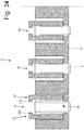
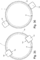
- the teeth 128 of the jaws 27 prevent the passage of the sealing rings 7 and also of the tubular casings 2 when the jaws 27 are in the gripping position (illustrated in the two seats 16 on the right in Figure 34 and illustrated in Figure 35 ); consequently, in the feeding station S5 it is necessary to move the jaws 27 from the gripping position (illustrated in the two seats 16 on the right in Figure 34 and illustrated in Figure 35 ) to the transfer position (illustrated in the seat 16 on the left in Figure 34 and illustrated in Figure 36 ) to initially allow the tubular casings 2 contained in the seats 16 to be raised towards the fingers 88 (and then towards the corresponding seats 89 containing the sealing rings 7) and subsequently allow the descent of the tubular casings 2 coupled to the corresponding sealing rings 7, again, inside the seats 16.
Landscapes
- Engineering & Computer Science (AREA)
- Mechanical Engineering (AREA)
- Cigarettes, Filters, And Manufacturing Of Filters (AREA)
- Automatic Assembly (AREA)
- Closing Of Containers (AREA)
- Package Closures (AREA)
- Making Paper Articles (AREA)
Abstract
Description
- The present invention relates to a manufacturing machine for the production of disposable cartridges for electronic cigarettes.
- Recently, disposable (i.e. single use) cartridges have been proposed for electronic cigarettes comprising a tubular-shaped casing made of a plastic material with a micro-perforated bottom wall and a quantity of powdered tobacco is contained therein with a tab made of filtering material on top; the casing is closed at an upper end (i.e. opposite to the micro-perforated bottom wall) by means of a sealing ring which is welded to the casing.
- The production of said cartridges provides for filling each casing with a calibrated quantity of powdered tobacco, slightly compressing the quantity of powdered tobacco inside the casing so as to obtain the desired density and then capping the casing by applying both the tab of filtering material and the sealing ring to the open upper end. The cartridges are subsequently individually weighed in order to allow discarding of non-compliant ones which contain an insufficient or excessive amount of powdered tobacco therein.
- Once the production of the cartridges is finished, the latter are inserted inside sealed packages, typically blister packets.
- Patent applications
WO2017051348A1 ,WO2017051349A1 andWO2017051350A1 provide an example of a manufacturing machine for the production of disposable cartridges for electronic cigarettes of the type described above. This manufacturing machine is able to operate efficiently (i.e. with a high hourly production rate, in terms of the number of cartridges produced per time unit) and effectively (i.e. with a small number of discarded pieces and with a high final quality); however, electronic cigarettes that use the above-described cartridge are experiencing considerable market success and therefore the manufacturers of the above-described cartridges require an even more performing manufacturing machine, i.e. with a higher hourly production rate, compared to the known manufacturing machine described in the patent applicationsWO2017051348A1 ,WO2017051349A1 andWO2017051350A1 . - The patent
US4782644A provides a further example of a manufacturing machine for the production of disposable cartridges for electronic cigarettes; however, this manufacturing machine is not capable of operating efficiently (i.e. with a high hourly production rate, in terms of the number of cartridges produced per time unit) - The object of the present invention is to provide a manufacturing machine for the production of disposable cartridges for electronic cigarettes, the which filling unit allows to achieve increased productivity while ensuring high quality standards and, at the same time, being easy and inexpensive to produce.
- According to the present invention, a manufacturing machine is provided for the production of disposable cartridges for electronic cigarettes, according to what is claimed in the appended claims.
- The claims describe preferred embodiments of the present invention forming an integral part of the present disclosure.
- The present invention will now be described with reference to the attached drawings, which illustrate some non-limiting embodiments thereof, wherein:
-
Figure 1 is a longitudinal section view of a cartridge for an electronic cigarette; -
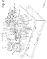
Figure 2 is a perspective view of a manufacturing machine which produces the cartridge for the electronic cigarette ofFigure 1 ; -
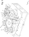
Figure 3 is a perspective view of the manufacturing machine ofFigure 2 with some parts removed for clarity; -
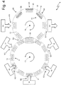
Figure 4 is a schematic plan view of the manufacturing machine ofFigure 2 ; -
Figure 5 is a schematic and longitudinal section view of part of a first manufacturing drum of the manufacturing machine ofFigure 2 ; -
Figure 6 is a schematic and longitudinal section view of part of a second manufacturing drum of the manufacturing machine ofFigure 2 ; -
Figure 7 is a schematic plan view of a feeding unit of the manufacturing machine ofFigure 2 ; -
Figures 8 and 9 are two enlarged-scale views of some fingers of the feeding unit for the tubular casings ofFigure 7 in an expanded configuration and in a compressed configuration, respectively; -
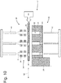
Figures 10 and11 are two schematic and longitudinal section views of part of the feeding unit ofFigure 7 at an insertion station and at two different operating times; -
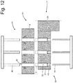
Figure 12 is a schematic and longitudinal section view of part of the feeding unit ofFigure 7 at an insertion station; -
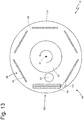
Figure 13 is a schematic plan view of a filling unit of the manufacturing machine ofFigure 2 ; -
Figure 14 is a schematic and longitudinal section view of part of the filling unit ofFigure 13 ; -
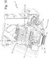
Figure 15 is a perspective view, and with parts removed for clarity, of a feeding unit of tabs of filtering material of the manufacturing machine ofFigure 2 ; -
Figures 16 and17 are two schematic side views of the feeding unit ofFigure 15 at two different operating times; -
Figure 18 is a schematic and front view of a hopper and of a cutting device of the feeding unit ofFigure 15 ; -
Figure 19 is a schematic and partially longitudinal section view of a distributing device of the feeding unit ofFigure 15 ; -
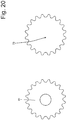
Figure 20 is a schematic plan view of a pusher and of a corresponding delivering channel of the feeding unit ofFigure 15 ; -
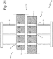
Figure 21 is a schematic and longitudinal section view of a transfer unit of the manufacturing machine ofFigure 2 ; -
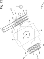
Figure 22 is a schematic plan view of a feeding unit of the sealing rings of the manufacturing machine ofFigure 2 ; -
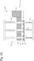
Figure 23 is a schematic and longitudinal section view of part of the feeding unit ofFigure 22 at an insertion station; -
Figure 24 is a schematic and longitudinal section view of part of the feeding unit ofFigure 22 at a feeding station; -
Figure 25 is a schematic and longitudinal section view of a welding unit of the manufacturing machine ofFigure 2 ; -
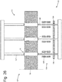
Figure 26 is a schematic and longitudinal section view of an extraction unit of the manufacturing machine ofFigure 2 ; -
Figure 27 is a schematic plan view of a control station of the manufacturing machine ofFigure 2 ; -
Figures 28 and29 are two schematic and longitudinal section views of an alternative of the feeding unit ofFigure 7 at an insertion station and at two different operating times; -
Figure 30 is a schematic plan view of a centring device of the feeding unit ofFigures 28 and29 ; -
Figures 31 and32 are two schematic and longitudinal section views of an alternative of the feeding unit ofFigure 22 at an insertion station and at two different operating times; -
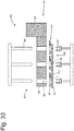
Figure 33 is a schematic and longitudinal section view of a further alternative of the feeding unit ofFigure 22 at an insertion station; -
Figure 34 is a schematic and longitudinal section view of part of a second manufacturing drum in an alternative of the manufacturing machine ofFigure 2 ; -
Figures 35 and 36 are two schematic top views of a seat of the second manufacturing drum ofFigure 34 with a pair of jaws arranged respectively in a gripping position and in a transfer position. -
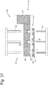
Figure 37 is a schematic and longitudinal section view of part of an alternative embodiment of the feeding unit ofFigure 22 at an insertion station; -
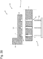
Figure 38 is a schematic and longitudinal section view of part of the feeding unit ofFigure 37 at a feeding station; -
Figure 39 is a schematic section view and on an enlarged scale, of a detail of the feeding unit ofFigure 37 ; -
Figure 40 is a schematic plan view of the detail ofFigure 39 ; and -
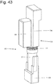
Figures 41 ,42 and43 schematically illustrate the coupling of an individual sealing ring to a corresponding tubular casing by means of the feeding unit ofFigure 37 . - In
Figure 1 , thenumber 1 denotes, as a whole, a disposable cartridge for electronic cigarettes. Thedisposable cartridge 1 comprises atubular casing 2 made of plastic material having amicro-perforated bottom wall 3 and a substantially cylindrical-shaped side wall 4; inside the tubular casing 2 aquantity 5 of powdered tobacco (in contact with the bottom wall 3) is contained therein with atab 6 of filtering material on top. Finally, thedisposable cartridge 1 comprises a sealing ring 7 (i.e. a sealing washer 7) which is inserted around an upper end (otherwise completely open) of thetubular casing 2 so as to prevent thetab 6 of filtering material from escaping; preferably, thesealing ring 7 is welded to thetubular casing 2. According to a preferred but non-binding embodiment illustrated in the attached figures, thetubular casing 2 has a bulge (i.e. a transversely larger portion) near the upper end (i.e. of the end opposite to thebottom wall 3 and near the sealing ring 7); this bulge determines the presence of an undercut near the upper end. - In
Figures 2 and3 , thenumber 8 denotes, as a whole, a manufacturing machine for the production of thedisposable cartridges 1 described above. Themanufacturing machine 8 performs an intermittent movement, i.e. its conveyors cyclically alternate motion steps and still steps. - As illustrated in
Figure 4 , themanufacturing machine 8 comprises amanufacturing drum 9 which is arranged horizontally and is mounted in a rotatable stepwise manner around avertical rotation axis 10; in other words, themanufacturing drum 9 is set into rotation with an intermittent motion, i.e. a non-continuous motion which provides a cyclical alternation of motion steps, wherein themanufacturing drum 9 is moving, and of still steps, in which themanufacturing drum 9 stops. Themanufacturing drum 9 supports twelvegroups 11 ofseats 12, each of which is adapted to receive and contain a correspondingtubular casing 2; in particular, eachgroup 11 comprises forty-twoseats 12 aligned along three straight lines parallel to each other (each of the three straight lines has fourteen seats 12) and the twelvegroups 11 are arranged to define, in plan, a regular polygon (i.e. a dodecahedron) on the surface of themanufacturing drum 9. - The
manufacturing machine 8 comprises afurther manufacturing drum 13 which is arranged horizontally beside themanufacturing drum 9 and is mounted in a rotatable stepwise manner around avertical rotation axis 14 parallel to therotation axis 10; in other words, themanufacturing drum 13 is set into rotation with an intermittent motion, i.e. a non-continuous motion which provides a cyclical alternation of motion steps, wherein themanufacturing drum 13 is moving, and still steps, wherein themanufacturing drum 13 stops. Themanufacturing drum 13 supports twelvegroups 15 ofseats 16, each of which is adapted to receive and contain a correspondingtubular casing 2; in particular, eachgroup 15 comprises forty-twoseats 16 aligned along three straight lines parallel to each other (each of the three straight lines has fourteen seats 16) and the twelvegroups 15 are arranged to define, in plan, a regular polygon (i.e. a dodecahedron) on the surface of themanufacturing drum 13. - The
manufacturing machine 8 comprises a feeding station S1, in which afeeding unit 17 inserts a corresponding emptytubular casing 2 in eachseat 12 of agroup 11, that is standing still; in particular, thefeeding unit 17 simultaneously inserts forty-two emptytubular casings 2 into asmany seats 12 of agroup 11 that is standing still in the feeding station S1. Downstream of the feeding station S1, relative to the rotation direction of themanufacturing drum 9, three filling stations S2 are arranged in succession, in each of which afilling unit 18 is arranged, which feeds acorresponding quantity 5 of tobacco into eachtubular casing 2 carried by aseat 12 of agroup 11, that is standing still; in particular, eachfilling unit 18 simultaneously feeds fourteenquantities 5 of tobacco into asmany seats 12 of agroup 11 that is standing still in the feeding station S2. Thefilling unit 18 of the first feeding station S2 feeds fourteenquantities 5 of tobacco into asmany seats 12 of the innermost row of thegroup 11 that is standing still in the first feeding station S2, thefilling unit 18 of the second feeding station S2 feeds fourteenquantities 5 of tobacco into asmany seats 12 of the intermediate row of thegroup 11 that is standing still in the second feeding station S2, and thefilling unit 18 of the third feeding station S2 feeds fourteenquantities 5 of tobacco into asmany seats 12 of the outermost row of thegroup 11 that is standing still in the third feeding station S2. - Downstream of the filling stations S2 (i.e. downstream of the last filling station S2), relative to the rotation direction of the
manufacturing drum 9, a feeding station S3 is arranged, in which afeeding unit 19 feeds acorresponding tab 6 of filtering material into eachtubular casing 2 carried by aseat 12 of agroup 11, that is standing still; in particular, the fillingunit 19 simultaneously feeds forty-twotabs 6 of filtering material into asmany seats 12 of agroup 11 that is standing still in the feeding station S3. - Downstream of the feeding station S3, relative to the rotation direction of the
manufacturing drum 9, a transfer station S4 is arranged, in which atransfer unit 20 transfers the tubular casings 2 (each containing aquantity 5 of tobacco and atab 6 of filtering material) from theseats 12 of agroup 11 of themanufacturing drum 9 to theseats 16 of agroup 15 of themanufacturing drum 13; in particular, thetransfer unit 20 simultaneously transfers forty-twotubular casings 2 from asmany seats 12 of agroup 11 that is standing still in the transfer station S4 to asmany seats 16 of agroup 15 that is standing still in the transfer station S4. In the transfer station S4, the twomanufacturing drums seats 12 of agroup 11 of themanufacturing drum 9 are vertically aligned with theseats 16 of agroup 15 of themanufacturing drum 13; consequently, in the transfer station S4 the transfer of thetubular casings 2 takes place by means of a linear and vertical movement (i.e. a rise of thecasings 2 if themanufacturing drum 9 is arranged below themanufacturing drum 13 or a lowering of thecasings 2 if themanufacturing drum 9 is arranged above the manufacturing drum 13) . - Downstream of the insertion station S4, relative to the rotation direction of the
manufacturing drum 13, a feeding station S5 is arranged, in which afeeding unit 21 feeds acorresponding sealing ring 7 into eachtubular casing 2 carried by aseat 16 of agroup 15, that is standing still; in particular, the fillingunit 21 simultaneously feeds forty-twosealing rings 7 into asmany seats 16 of agroup 15 that is standing still in the feeding station S5. Downstream of the feeding station S5, relative to the rotation direction of themanufacturing drum 13, three welding stations S6 are arranged in succession, in each of which awelding unit 22 performs (preferably by ultrasonic welding) the welding of each sealingring 7 to the correspondingtubular casing 2 carried by aseat 16 of agroup 15 that is standing still; in particular, eachwelding unit 22 simultaneously welds fourteen sealingrings 7 to as manytubular casings 2 carried by theseats 16 of agroup 15 that is standing still in the welding station S6. Thewelding unit 22 of the first welding station S6 welds fourteen sealingrings 7 in asmany seats 16 of the intermediate row of thegroup 15 that is standing still in the first welding station S6, thewelding unit 22 of the second welding station S6 welds fourteen sealingrings 7 in asmany seats 16 of the outermost row of thegroup 15 that is standing still in the second welding station S6, and thewelding unit 22 of the third welding station S6 welds fourteen sealingrings 7 in asmany seats 16 of the innermost row of thegroup 15 that is standing still in the third welding station S6. - In the welding stations S6, the manufacturing of the
disposable cartridges 1 is completed, i.e. downstream of the welding stations S6 thedisposable cartridges 1 are finished and ready for use. Downstream of the welding stations S6 (i.e. downstream of the last welding station S6), relative to the rotation direction of themanufacturing drum 13, an output station S7 is arranged, in which anextraction unit 23 extracts a correspondingdisposable cartridge 1 out of eachseat 16 of agroup 15 that is standing still; in particular, theextraction unit 23 simultaneously extracts forty-twodisposable cartridges 1 out of asmany seats 16 of agroup 15 that is standing still in the output station S7. - From the foregoing it is clear that all the steps of the production process of the disposable cartridges 1 (such as for example the filling of the
quantities 5 of tobacco, the feeding of thetabs 6 of filtering material, the feeding of the sealing rings 7, the welding of the sealing rings 7) contained in theseats 12/16 of asame group 11/15 are carried out in parallel, i.e. they are carried out simultaneously for a plurality (fourteen or forty-two) ofdisposable cartridges 1 contained in theseats 12/16 of asame group 11/15. - As illustrated in
Figure 5 , eachseat 12 of themanufacturing drum 13 comprises a housing throughchannel 24 which crosses themanufacturing drum 9 from side-to-side and is adapted to contain atubular casing 2; in particular, eachhousing channel 24 is transversely wider than atubular casing 2 so as to allow thetubular casing 2 to pass through the inside of the housing channel 24 (as will be described in the following, eachtubular casing 2 enters, from the bottom, thecorresponding housing channel 24 in the feeding station S1 and exits, from the top, thecorresponding housing channel 24 in the transfer station S4). Eachseat 12 of themanufacturing drum 13 further comprises a pair ofopposite jaws 25, which are mounted in thehousing channel 24 and are movable between a gripping position (illustrated in the twoseats 12 on the right inFigure 5 ) in which they engage atubular casing 2 arranged in the housing channel 24 (thus preventing the descent of thetubular casing 2 through the housing channel 24) and a transfer position (illustrated in theseat 12 on the left inFigure 5 ) in which they do not engage atubular casing 2 arranged in the housing channel 24 (thus allowing the free sliding of thetubular casing 2 along the housing channel 24). According to a preferred embodiment, theopposite jaws 25 are arranged immediately below the undercut formed by the transverse bulge of the upper part of thetubular casing 2 so that said undercut rests on thejaws 25 when thejaws 25 are arranged in the gripping position (illustrated in the twoseats 12 on the right inFigure 5 ). In the embodiment illustrated in the attached figures, the axial length of eachhousing channel 24 is (slightly) longer than the axial length of thetubular casings 2 and therefore thetubular casings 2 are completely contained (without any protrusion) in thehousing channels 24; according to other embodiments not illustrated and perfectly equivalent, the axial length of eachhousing channel 24 is much longer than the axial length of thetubular casings 2 or the axial length of eachhousing channel 24 is (slightly or much) shorter than the axial length of the tubular casings 2 (in this last case thetubular casings 2 are not completely contained in thehousing channels 24 and therefore protrude, at the top and/or at the bottom, from the housing channels 24). - In the embodiment illustrated in the attached figures, the two
jaws 25 of eachseat 12 have a limited axial extension, i.e. they are (much) shorter than thehousing channel 24; in other words, in the embodiment illustrated in the attached figures, the twojaws 25 of eachseat 12 engage a limited portion of thehousing channel 24 which has fixed walls above and below thejaws 25. According to an alternative and perfectly equivalent embodiment not illustrated, the twojaws 25 of eachseat 12 have a greater axial extension which can also coincide with the axial extension of the inside of thehousing channel 24; in other words, thehousing channel 24 may have fixed walls only above the twojaws 25, thehousing channel 24 may have fixed walls only below the twojaws 25, or thehousing channel 24 may not have fixed walls neither above nor below the two jaws 25 (i.e. thehousing channel 24 may not have fixed walls, but only two jaws 25). - As illustrated in
Figure 6 , eachseat 16 of themanufacturing drum 13 comprises a housing throughchannel 26 which crosses themanufacturing drum 13 from side-to-side and is adapted to contain atubular casing 2; in particular, eachhousing channel 26 is transversely wider than atubular casing 2 so as to allow thetubular casing 2 to pass through the inside of the housing channel 26 (as will be described in the following, eachtubular casing 2 enters, from the bottom, thecorresponding housing channel 26 in the feeding station S1 and always comes out of the bottom of thecorresponding housing channel 26 in the transfer station S4) . Eachseat 16 of themanufacturing drum 13 comprises, furthermore, a pair ofopposite jaws 27, which are mounted in thehousing channel 26 and are movable between a gripping position (illustrated in the twoseats 16 on the right inFigure 6 ) in which they engage atubular casing 2 arranged in the housing channel 26 (thus preventing the descent of thetubular casing 2 through the housing channel 26) and a transfer position (illustrated in theseat 16 on the left inFigure 6 ) in which they do not engage atubular casing 2 arranged in the housing channel 26 (thus allowing the free sliding of thetubular casing 2 along the housing channel 26). According to a preferred embodiment, theopposite jaws 27 are arranged immediately below the undercut formed by the transverse bulge of the upper part of thetubular casing 2 so that said undercut rests on thejaws 27 when thejaws 27 are arranged in the gripping position (illustrated in the twoseats 16 on the right inFigure 6 ). In the preferred embodiment illustrated in the attached figures, the axial length of eachhousing channel 26 is (slightly) shorter than the axial length of thetubular casings 2 and therefore thetubular casings 2 protrude (slightly), both at the top and at the bottom, from thehousing channels 26; according to other embodiments not illustrated and perfectly equivalent, the axial length of eachhousing channel 24 is (much or slightly) longer than the axial length of the tubular casings 2 (therefore thetubular casings 2 are completely contained, without any protrusion, in the housing channels 24) or the axial length of eachhousing channel 24 is greatly shorter than the axial length of the tubular casings 2 (in this latter case thetubular casings 2 widely protrude, both at the top and at the bottom, from the housing channels 26). - In the embodiment illustrated in the attached figures, the two
jaws 27 of eachseat 16 have a limited axial extension, i.e. they are (much) shorter than thehousing channel 26; in other words, in the embodiment illustrated in the attached figures, the twojaws 27 of eachseat 16 engage a limited portion of thehousing channel 26 which has fixed walls above and below thejaws 27. According to an alternative and perfectly equivalent embodiment not illustrated, the twojaws 27 of eachseat 16 have a greater axial extension which can also coincide with the axial extension of the inside of thehousing channel 26; in other words, thehousing channel 26 may have fixed walls only above the twojaws 27, thehousing channel 26 may have fixed walls only under the twojaws 27, or thehousing channel 26 may not have fixed walls neither above nor below the two jaws 27 (i.e. thehousing channel 26 may not have fixed walls, but only two jaws 27). - The
feeding unit 17 feeds thetubular casings 2 to theseats 12 of agroup 11 ofseats 12 that is standing still at the feeding unit 17 (i.e. that is standing still in the feeding station S1). As illustrated inFigure 7 , thefeeding unit 17 comprises a feeding drum 28 (having a parallelepiped shape) which is mounted in a rotatable stepwise manner around avertical rotation axis 29 parallel to therotation axis 10 of themanufacturing drum 9; the feedingdrum 28 supports twogroups 30 of opposite fingers 31 (i.e. the twogroups 30 are arranged on opposite sides of the rotation axis 28). Eachgroup 30 comprises fourteenfingers 31 which are parallel and next to one another and eachfinger 31 has threeseats 32, each adapted to receive a corresponding tubular casing 2 (as better illustrated inFigures 8 and 9 ); it is important to note that the number ofseats 32 of eachfinger 31 is equal to the number of lines of eachgroup 11 ofseats 12 of themanufacturing drum 9. As illustrated inFigures 10 ,11 and12 , eachsecond seat 32 is formed by a blind hole (obtained inside the corresponding finger 31) having a bottom wall on which a correspondingtubular casing 2 rests. - As illustrated in
Figure 7 , eachgroup 30 offingers 31 is adapted to receive corresponding tubular casings 2 (in particular forty-two tubular casings 2) in an insertion station S8 and is adapted to release the tubular casings 2 (in particular forty-two tubular casings 2) to thegroup 11 ofseats 12 of themanufacturing drum 9 that is standing still in the feeding station S1. Furthermore, eachfinger 31 is mounted on the feedingdrum 28 so as to translate relative to the feedingdrum 28 along a spacing direction D1 perpendicular to therotation axis 29 so as to move away from or closer to theadjacent fingers 31. The feedingdrum 28 is provided with anactuator device 33 which translates thefingers 31 along the spacing direction D1 so as to arrange thefingers 31 at a first mutual distance in the insertion station S8 and at a second mutual distance, which is different from the first mutual distance, in the feeding station S1; in the embodiment illustrated in the attached figures, the second mutual distance is greater than the first mutual distance. - In the embodiment illustrated in the attached figures, the
fingers 31 of eachgroup 30 move relative to one another by means of a translation along the spacing direction D1; according to a different and perfectly equivalent embodiment not illustrated, thefingers 31 of eachgroup 30 move relative to one another by means of a roto-translation or by means of a rotation which has a component along the spacing direction D1. - The function of the
actuator device 33 is to modify the pitch (i.e. the mutual distance) between thetubular casings 2 which, in the embodiment illustrated in the attached figures, have a 9.5 mm pitch in the insertion station S8 and have a 12 mm pitch in the feeding station S1. The increase in the pitch (i.e. the mutual distance) between thetubular casings 2 is clearly visible inFigures 8 and 9 showing the fingers 31 (carrying the seats 32) in the feeding station S1 (Figure 9 , pitch equal to 12 mm) and in the insertion station S8 (Figure 8 , pitch equal to 9.5 mm). According to a preferred embodiment, theactuator device 33 is a passive one (i.e. it has no sources which autonomously generate a movement) and uses cams which move thefingers 31 by using the rotation movement of the feedingdrum 28 around therotation axis 29; according to a preferred, but non-binding, embodiment, thecam actuator device 33 is of the desmodromic type devoid of elastic elements, i.e. the translation movement of thefingers 31 is always impressed by cams which move thefingers 31 in both directions without using elastic thrust. - It is important to note that, according to different embodiments equivalent to one another, the
actuator device 33 can translate thefingers 31 of eachgroup 30 into the feeding station S1 (when the feedingdrum 28 is standing still), in the insertion station S8 (when the feedingdrum 28 is standing still) or in the path between the feeding station S1 and the insertion station S8 (when the feedingdrum 28 is moving). Obviously, if theactuator device 33 comprises a motor (typically electric), then theactuator device 33 is able to translate thefingers 31 of eachgroup 30 even when the feedingdrum 28 is standing still; on the other hand, if theactuator device 33 comprises cams which exploit the rotary movement of the feedingdrum 28, then theactuator device 33 is able to translate thefingers 31 of eachgroup 30 only when the feedingdrum 28 is moving. - As illustrated in
Figure 7 , thefeeding unit 17 comprises three conveyingchannels 34 which are inclined downwards (but may also be horizontal) and feed three respective rows oftubular casings 2 towards the insertion station S8; as is clear inFigure 7 , in the feeding station S8 each conveyingchannel 34 is coupled (aligned) to acorresponding seat 32 in eachfinger 31. As better illustrated inFigures 10 and11 , each conveyingchannel 34 is laterally delimited by corresponding sides 35 (which can be doubled as illustrated in the attached figures, single, or triple) and is delimited, at the bottom, by asupport plane 36. The conveyingchannels 34 can feed the respective rows oftubular casings 2 solely by gravity (by exploiting the downward inclination) or by adding compressed air blowers (blower air conveyor) or vibrations (vibrating conveyor); alternatively, other configurations of the conveyingchannels 34 are also possible with the only constraint that the conveyingchannels 34 feed the respective rows oftubular casings 2 towards the insertion station S8. - As illustrated in
Figure 7 , thefeeding unit 17 also comprises an accompanyingelement 37 which has three parallel prongs, each of which is coupled to a corresponding conveyingchannel 34; in particular, the accompanyingelement 37 is movable within the conveyingchannels 34 and parallel to the conveyingchannels 34 to accompany the progressive descent of thetubular casings 2 inside the insertion station S8. Moreover, thefeeding unit 17 comprises agate 38 which is coupled to the conveyingchannels 34, is arranged immediately upstream of the insertion station S8 (i.e. delimits the beginning of the insertion station S8) and is movable between an opening position, in which it allows thetubular casings 2 to enter the insertion station S8 and a closing position which prevents thetubular casings 2 from entering the insertion station S8. - In use, when the insertion station S8 is full (i.e. when in the insertion station S8, there are forty-two
tubular casings 2 arranged in three rows of fourteentubular casings 2 in the three conveyingchannels 34 as illustrated inFigure 7 ), thegate 38 it is closed (i.e. it is arranged in the closing position) so as to "isolate" the segments of the conveyingchannels 34 comprised in the insertion station S8 from the remaining parts of the conveyingchannels 34 and then the forty-twotubular casings 2 present in the insertion station S8 are transferred (with the methods described in the following) from the conveyingchannels 34 to theseats 32 of thefingers 31 of agroup 30 that is standing still in the insertion station S8. When the forty-two tubular casings present in the insertion station S8 have been transferred from the conveyingchannels 34 to theseats 32 of thefingers 31 of agroup 30 that is standing still in the insertion station S8, the insertion station S8 is empty (i.e. completely devoid of tubular casings 2); at this point, the prongs of the accompanyingdevice 37 are fed along the conveyingchannels 34 until reaching thegate 38 and therefore thegate 38 is opened (i.e. is arranged in the opening position) so as to allow thetubular casings 2 to enter the insertion station S8 again sliding by gravity along the three conveyingchannels 34; the descent of thetubular casings 2 along the three conveyingchannels 34 and in the insertion station S8 is not free (i.e. uncontrolled) but is controlled by the three prongs of the accompanyingelement 37 which rest on the corresponding first threetubular casings 2 to accompany, at a controlled and predetermined rate, the descent of the first three tubular casings 2 (followed by the other tubular casings 2) along the three conveyingchannels 34. Due to the action of the accompanyingelement 37, thetubular casings 2 are never "abandoned" and therefore have no possibility of "tilting" inside the conveyingchannels 34. - According to a preferred embodiment, the
gate 38 comprises, for each conveyingchannel 34, a corresponding wedge-shaped stopping element which is inserted (in the closing position) between two successivetubular casings 2 to prevent further advancement of thetubular casing 2 arranged upstream along the conveyingchannel 34. - As illustrated in
Figures 10 and11 , in the insertion station S8 theseats 32 of thefingers 31 are aligned with the corresponding conveyingchannels 34 and are arranged under the corresponding conveyingchannels 34 so that eachtubular casing 2 carried by a conveyingchannel 34 is vertically aligned with acorresponding seat 32 of thefingers 31. As previously said, the conveyingchannels 34 comprise asupport plane 36 on which thetubular casings 2 rest. In the insertion station S8, thesupport plane 36 has a plurality of through-holes 39, each of which is adapted to allow the passage of atubular casing 2; moreover, thesupport plane 36, at least in the insertion station S8, is movable (under the thrust of an actuator device 40) between a filling position (illustrated inFigure 10 ) in which the through-holes 39 are not aligned with respect to the corresponding conveyingchannels 34 so as to prevent the passage of thetubular casings 2 through the through-holes 39 (i.e. so as to misalign the through-holes 39 relative to thetubular casings 2 contained in the conveying channels 34) and a transfer position (illustrated inFigure 11 ) in which the through-holes 39 are aligned with the corresponding conveyingchannels 34 so as to allow the passage of thetubular casings 2 through the through-holes 39 (i.e. to align the through-holes 39 relative to thetubular casings 2 contained in the conveying channels 34). In particular, theactuator device 40 moves thesupport plane 36 between the filling position (illustrated inFigure 10 ) and the transfer position (illustrated inFigure 11 ) by translating thesupport plane 36 along a control direction D2 which is perpendicular to the spacing direction D1, is perpendicular to therotation axis 29, and is perpendicular to the conveyingchannels 34. According to a possible embodiment, the through-holes 39 are not separated from one another, and, together form a single slot (i.e. a single large through-hole 39 which has an elongated shape). - As illustrated in
Figures 10 and11 , thefeeding unit 17 comprises a group of (forty-two)pushers 41 which are arranged in the insertion station S8 and are movable in a vertical manner for pushing thetubular casings 2 from the conveyingchannel 34 to theseats 32 of thefingers 31 of agroup 30 that is standing still in the insertion station S8; furthermore, thefeeding unit 17 comprises a group of (forty-two) accompanyingelements 42 which are opposite to thepushers 41 and are movable in a vertical manner so as to be inserted into theseats 32 of thefingers 31 of agroup 30 that is standing still in the insertion station S8 and to accompany the descent of thetubular casings 2 from the conveyingchannel 34 to theseats 32 of thefingers 31. Eachseat 32 of thefingers 31 has, at the bottom, a through-hole 43 (small enough to prevent the entry of a tubular casing) through which an accompanyingelement 42 can enter theseat 32 from below. - In other words, in the insertion station S8, each
tubular casing 2 is transferred by a conveying channel 34 (passing through a through-hole 39 of the support plane 36) to theunderlying seat 32 of afinger 31 of agroup 30 that is standing still in the insertion station S8 thus performing a vertical downward movement during which thetubular casing 2 is engaged, at the top, by apusher 41 and at the bottom by an accompanying device 42 (i.e. being "pinched" between apusher 41 arranged at the top and by an accompanyingelement 42 arranged at the bottom). In this regard, it is important to note thatpushers 41 and the accompanyingelements 42 would not be strictly necessary, since the vertical downward movement would in any case be impressed onto thetubular casings 2 by the force of gravity; however, the presence of thepushers 41 and of the accompanyingelements 42 allows to impart a controlled movement to thetubular casings 2 which prevents any incorrect positioning or bouncing of thetubular casings 2. - As illustrated in
Figure 12 , theseats 32 of thefingers 31 of agroup 30 that is standing still in the feeding station S1 are aligned with the correspondingseats 12 of agroup 11 that is standing still in the feeding station S1 so that eachtubular casing 2 carried by aseat 32 of thefingers 31 is vertically aligned with acorresponding seat 12 of themanufacturing drum 9. As illustrated inFigure 12 , thefeeding unit 17 comprises a group of (forty-two)pushers 44 which are arranged in the feeding station S1 and are movable in a vertical manner to be inserted (by means of the through-holes 43) inside theseats 32 of thefingers 31 of agroup 30 that is standing still in the feeding station S1 thus pushing thetubular casings 2 from theseats 32 of thefingers 31 to theseats 12 of agroup 11 that is standing still in the feeding station S1; moreover, thefeeding unit 17 comprises a group of (forty-two) accompanyingelements 45 which are opposite to thepushers 44 and are movable in a vertical manner to accompany the ascent of thetubular casings 2 from theseats 32 of thefingers 31 to theseats 12 of themanufacturing drum 9. As previously stated, eachseat 32 of thefingers 31 has a through-hole 43 (small enough to prevent the entry of a tubular casing 2) in the lower part, through which apusher 44 can enter into theseat 32 from below. - In other words, in the feeding station S1 each
tubular casing 2 is transferred from aseat 32 of afinger 31 of agroup 30 that is standing still in the feeding station S1 to theoverlying seat 12 of agroup 11 that is standing still in the feeding station S1 by performing a vertical upward movement during which thetubular casing 2 is engaged at the bottom by apusher 44 and, at the top, by an accompanying element 45 (i.e. being "pinched" between apusher 44 arranged at the bottom and by an accompanyingelement 45 arranged at the top). In this regard it is important to note that accompanyingelements 45 would not be strictly necessary; however, the presence of the accompanyingelements 45 allows to impart a controlled movement to thetubular casings 2 which prevents any incorrect positioning or bouncing of thetubular casings 2. - As previously stated, each
seat 12 of themanufacturing drum 9 comprises a housing throughchannel 24 which crosses themanufacturing drum 9 from side-to-side and is adapted to contain atubular casing 2 and a pair ofopposite jaws 25, which are fitted into thehousing channel 24 and are movable between a gripping position, in which they engage atubular casing 2 arranged in thehousing channel 24 and a transfer position, in which they do not engage atubular casing 2 arranged in thehousing channel 24. During the entering of atubular casing 2 into acorresponding seat 12 of themanufacturing drum 9, the twojaws 25 are kept in the transfer position and then, only when the entering oftubular casing 2 into theseat 12 has been completed, the twojaws 25 are brought into the gripping position. - Each filling
unit 18 is similar, in its general structure, to the filling unit described and illustrated in the patent applicationsWO2017051348A1 ,WO2017051349A1 andWO2017051350A1 to which we refer for a more detailed description of the fillingunit 18. - As illustrated in
Figure 13 , each fillingunit 18 comprises a cylindrical-shapedtank 46 which is arranged horizontally and is mounted in a rotatable stepwise manner around avertical rotation axis 47 parallel to therotation axis 10; in other words, thetank 46 is set into rotation with an intermittent motion, i.e. a non-continuous motion which provides a cyclical alternation of steps of motion, wherein thetank 46 is moving, and still steps, wherein thetank 46 stops. Eachtank 46 is arranged beside themanufacturing drum 9 and partially overlapping themanufacturing drum 9 at the filling station S2; in particular, thetank 46 is arranged higher than themanufacturing drum 9 so as to be on top of themanufacturing drum 9 at the filling station S2 (as illustrated inFigure 14 ). Eachtank 46 supports sixgroups 48 ofseats 49, each of which is adapted to receive and contain acorresponding quantity 5 of tobacco; in particular, eachgroup 48 comprises fourteenseats 49 aligned along a straight line and the sixgroups 48 are arranged to define, in plan, a regular polygon (i.e. a hexagon) on the surface of theannular tank 46. - Each
tank 46 is delimited at the bottom by abase disc 50 having a circular shape and is delimited, on the sides, by acylindrical side wall 51 which projects perpendicular from thebase disc 50; theseats 49 are obtained in thebase disc 50, i.e. they are (partially) formed by circular through-holes made through thebase disc 50. Centrally, from thebase disc 50, a cylindricalcentral element 52 rises, which gives an annular shape (i.e. a "donut" shape) to the inner volume of thetank 46. - Each
tank 46 is coupled to acylindrical feeding duct 53 which is oriented in a vertical manner (at least in its end portion) and has an outlet opening arranged inside thetank 46; the feedingduct 53 continuously feeds, inside thetank 46, a flow of tobacco which forms a bed resting on thebase disc 50 of thetank 46. - Each filling
unit 18 comprises atransfer device 54 which is arranged in a fixed position (i.e. without rotating together with the tank 46) at the filling station S2 and cyclically transfers thequantities 5 of tobacco contained in theseats 49 of agroup 48 that is standing still in the filling station S2 into correspondingseats 12 of agroup 11 that is standing still in the filling station S2 of themanufacturing drum 9. As illustrated inFigure 14 , in each filling station S2, the tank 46 (i.e. thebase disc 50 of the tank 46) is partially overlapping themanufacturing drum 9 so that theseats 49 of agroup 48 of thetank 46 are vertically aligned and arranged above theseats 12 of agroup 11 of themanufacturing drum 9; consequently, in each filling station S2 the transfer of thequantities 5 of tobacco takes place by means of a linear and vertical downward movement (i.e. a descent of thequantities 5 of tobacco). Eachtransfer device 54 comprises a plurality ofpushers 55, each of which is coupled to acorresponding seat 49 of agroup 48 that is standing still in the filling station S2 and is provided with an alternating vertical motion for pushing thequantity 5 of tobacco contained in thecorresponding seat 49 downwards, i.e. towards a correspondingtubular casing 2 that is standing still. - As illustrated in
Figure 14 , under thebase disc 50, a furtherintermediate disc 56 is arranged, which is interposed between thebase disc 50 and the manufacturing drum 9 (i.e. between theseats 49 containing thequantities 5 of tobacco and theseats 12 containing the tubular casings 2); through theintermediate disc 56 groups of through-holes are formed, which are internally lined by means of respective feeding ducts 57 which protrude downwardly towards the outside of theintermediate disc 56. In use, eachtubular casing 2, which is housed in aseat 12 of themanufacturing drum 9 and that is standing still in the corresponding filling station S2, is pushed upwards (i.e. towards the intermediate disc 56) by apusher 58 so as to bring its upper open end in contact with the mouth of the respective feeding duct 57. According to a possible embodiment, the outlet mouth of each feeding duct 57 can be funnel-shaped (i.e. a truncated-conical shape). According to a possible embodiment, the outlet mouth of each feeding duct 57 can be inserted partially inside the open upper end of a correspondingtubular casing 2 when thetubular casing 2 is pushed upward (i.e. towards the intermediate disc 56) by the correspondingpusher 58. - According to a preferred embodiment illustrated in
Figure 14 , eachseat 49 has a variable axial size (therefore a variable volume) due to a telescopic mechanism: eachseat 49 is formed by a through-hole made through thebase disc 50 which is lined by means of atubular liner 59 and by a furthertubular liner 60 which is partially arranged around thetubular liner 59 and can slide relative to thetubular liner 59. In use, the tubular liners 60 (together with the underlying intermediate disc 56) can axially slide so as to vary the overall volume of theseats 49. - Immediately below each
group 48 of seats 49 ashutter element 61 is arranged, which is provided, for eachseat 49, with a plug 62 which is permeable to air (but not to tobacco) and with a through-hole 63 arranged beside the plug 62. Eachshutter element 61 is movably mounted so as to move radially under the thrust of anactuator device 64, between a closing position (illustrated inFigure 14 ) in which a corresponding plug 62 is arranged below eachseat 49 for closing theseat 49 at the bottom and prevent the descent of the tobacco and an opening position, in which a corresponding through-hole 63 is arranged below eachseat 49 so as so as to allow the descent of the tobacco. In use, theactuator device 64 keeps eachshutter element 61 in the closing position (illustrated inFigure 14 ) outside of the filling station S2 and moves theshutter element 61 to the opening position inside the filling station S2 so as to allow the descent of thequantity 5 of tobacco from theseat 49 towards a correspondingtubular casing 2 carried by aseat 12 of themanufacturing drum 9. - In the illustrated embodiment, each plug 62 is permeable to air (but not to tobacco) so as to allow a bottom suction to be applied to the
seats 49, which tends to favor the entering of the tobacco into theseats 49; in particular, each plug 62 is permeable to air due to the presence of a plurality of through-holes of a size smaller than the size of the tobacco fibers so that air can pass through said through-holes but not tobacco. In use, during the formation of thequantities 5 of tobacco (i.e. on the outside of the filling station S2) a suction source is connected to the feeding ducts 57, so as to generate a depression inside the feeding ducts 57 that, through the plugs 62 which are permeable to air, is also provided inside theseats 49, thus favoring the entering of the tobacco into theseats 49. - According to a different embodiment, not illustrated, each plug 62 is completely sealed (i.e. it is not permeable to air nor to tobacco).
- According to a preferred embodiment, the
actuator device 64 controls the sliding of the shutter elements 61 (there is ashutter element 61 for eachgroup 48 of seats 49) independently of the rotation of thetank 46 around therotation axis 47; in this way it is possible to rotate thetank 46 around therotation axis 47 without letting thequantities 5 of tobacco descend towards thetubular casings 2 in the corresponding filling station S2. Said possibility (i.e. the rotation of thetank 46 around therotation axis 47 without the descent of thequantities 5 of tobacco) is used when themanufacturing machine 8 is started, following a stop, so as to allow the formation of an uniform tobacco bed and with an adequate thickness inside thetank 46 before letting thequantities 5 of tobacco descend and when themanufacturing machine 8 is a function and, for some malfunctioning and/or discard, in a filling station S2 there are not (all) of thetubular casings 2 . - According to a possible embodiment, the
actuator device 64 controls the sliding of theshutter elements 61 so that when thequantities 5 of tobacco are removed from theseats 49 each shutter element 61 (quickly) carries out a succession of strokes between the closing position and the opening position (i.e. opens and closes theseats 49 several times) in order to "shake" theseats 49 and therefore favor the descent of all the tobacco present inside theseats 49. - According to a possible embodiment illustrated in
Figures 13 and14 , each fillingunit 18 comprises acleaning device 110, which is arranged in a fixed position (i.e. does not rotate with the tank 26) at the filling station S2 so as to perform the cleaning of the air-permeable plugs 62, namely to free the air-permeable plugs 62 from any tobacco residues "stuck" in the through-holes of the plugs 62 before theseats 49 are filled withnew quantities 5 of tobacco. In other words, after having emptied theseats 49 of thetank 46 by transferring thecorresponding quantities 5 of tobacco from theseats 49 of thetank 46 to theseats 12 of agroup 11 that is standing still in the filling station S2 and before starting again the filling of theseats 49 of thetank 46 with other tobacco in order to reform thequantities 5 of tobacco, the air-permeable plugs 62 are cleaned by means of thecleaning device 110 which eliminates any tobacco residues "stuck" in the through-holes of the air-permeable plugs 62. It is important to note that thecleaning device 110 can clean the air-permeable plugs 62 at each cycle, every group of cycles (for example every 3-5 cycles), or occasionally. According to a preferred embodiment, thecleaning device 110 aims powerful compressed air jets at the air-permeable plugs 62 to free the through-holes of the air-permeable plugs 62 from any foreign objects; consequently, for each air-permeable plug 62 thecleaning device 110 comprises (at least) a corresponding nozzle which aims a compressed air jet at the plug 62. According to a possible embodiment, thecleaning device 110 is arranged beside theseats 49 in order to act on the air-permeable plugs 62 when the plugs 62 are moved away from theseats 49 by the movement of theshutter element 61; in this embodiment, the air-permeable plugs 62 are cleaned by thecleaning device 110 when they are (relatively) far from theseats 49, i.e. when theseats 49 are opened at the bottom to release thecorresponding quantities 5 of tobacco. According to an alternative embodiment, thecleaning device 110 is arranged at theseats 49 to act on the air-permeable plugs 62 when the plugs 62 are coupled to theseats 49; obviously this cleaning is done after having extracted thequantities 5 of tobacco from theseats 49 and before starting the entry of new tobacco into theseats 49. - As illustrated in
Figures 16 and17 , thetabs 6 of filtering material are obtained by means of the transverse cut of correspondingpieces 65 of filtering material; i.e. thepieces 65 of filtering material are "sliced" in order to obtain thetabs 6 of filtering material. In this regard, it is important to note that the axial length of eachpiece 65 of filtering material is equal to an internal multiple of the axial length of atab 6 of filtering material; for example, eachpiece 65 of filtering material could have an axial length of 114 mm and eachtab 6 of filtering material has an axial length of 4.75 mm (therefore, from eachpiece 65 of filtering material, twenty-fourtabs 6 of filtering material are obtained). - The feeding unit 19 (illustrated as a whole in
Figure 15 ) comprises a supplyingdevice 66 which supplies a group ofpieces 65 of filtering material; in the embodiment illustrated in the attached figures, said group comprises fourteenpieces 65 of filtering material, i.e. a number ofpieces 65 of filtering material equal to the number ofseats 12 in a line of agroup 11. Furthermore, thefeeding unit 19 comprises acutting device 67 which cyclically carries out a transverse cut of the group ofpieces 65 of filtering material in order to separate a respective group oftabs 6 of filtering material from the group ofpieces 65 of filtering material. Finally, thefeeding unit 19 comprises atransfer device 68 which picks up the group oftabs 6 of filtering material immediately after the transverse cut and inserts thetabs 6 of filtering material into the correspondingseats 12 of agroup 11 that is standing still in the feeding station S3. - The supplying
device 66 comprises a hopper 69 (better illustrated inFigure 18 ) provided with a group ofvertical channels 70 which receive a plurality ofpieces 65 of filtering material; along thevertical channels 70 thepieces 65 of filtering material descend by gravity until reaching a lower portion at which thepieces 65 of filtering material are axially extracted from the hopper 69 (i.e. they are axially pushed out of the hopper 69). The supplyingdevice 66 comprises a group of horizontal pushers 71 (only one of which is visible inFigures 16 and17 ), each engaging a lower portion of a correspondingvertical channel 70 so as to progressively push apiece 65 of filtering material out of thevertical channel 70 and towards the cuttingdevice 67. - According to a preferred embodiment, the
pieces 65 of filtering material come from individual distributing devices which are loaded into an upper hopper and then supplied to a deep reaching drum which, by means of a pair of blades mounted on the same axis, removes the end terminals of each filter both for the purpose of obtainingpieces 65 of filtering material of the desired length with a precision of the length higher than the initial one, and of removing the ends which could have dents or wrinkles due to storage and transport. The flow of the trimmedpieces 65 of filtering material is brought to a height and conveyed by means of traditional down-drop inside a vertical chimney which feeds thehopper 69, in which thepieces 65 of filtering material are separated and spaced apart by step to then fall, one row at a time, at the base of thehopper 69 where thehorizontal pushers 71 extract thepieces 65 of filtering material. - According to a preferred embodiment, each
horizontal pusher 71 has a free end which comes into contact with acorresponding piece 65 of filtering material (i.e. with a base wall of thepiece 65 of filtering material opposite to the cutting device 67) and is provided with suction (i.e. is adapted to hold thepiece 65 of filtering material by means of suction). - As illustrated in
Figures 16 and17 , the supplyingdevice 66 comprises anactuator device 72 which imparts to the group of horizontal pusher 71 a work cycle comprising: a first delivery stroke, which brings thepieces 65 of filtering material from the lower portion of thevertical channels 70 to thecutting device 67, a subsequent plurality of second delivery strokes each having a range equal to the axial size of thetab 6 of filtering material, and finally one single return stroke which moves thehorizontal pushers 71 away from the cuttingdevice 67 returning thehorizontal pushers 71 to the outside of thevertical channels 70. In other words, initially eachhorizontal pusher 71 is arranged completely outside of the correspondingvertical channel 70 so as to allow the complete descent of apiece 65 of filtering material which then reaches the lower portion of thehopper 69; at this point eachhorizontal pusher 71 carries out the first delivery stroke during which thehorizontal pusher 71 enters the lower portion of thehopper 69 and pushes thepiece 65 of filtering material out of the lower portion of thehopper 69 until it reaches the cuttingdevice 67. Once the cuttingdevice 67 has been reached, eachhorizontal pusher 71 carries out in succession the second delivery strokes in order to allow thecutting device 67 to "slice" thepiece 65 of filtering material a little at a time thus obtaining thetabs 6 of filtering material. Once thepiece 65 of filtering material has been completely "sliced", eachhorizontal pusher 71 carries out the return stroke to exit the correspondingvertical channel 70 again, thus allowing the complete descent of anew piece 65 of filtering material and starting the work cycle again. - Preferably, the
actuator device 72 comprises its own electric motor which linearly moves thehorizontal pushers 71 and individually and independently performs every single second delivery stroke; in this way, theactuator device 72 cannot always make the same error in the length of the second outward strokes and therefore does not "sum" any errors in the length of the second outward strokes, thus preventing thelast tabs 6 of filtering material from being excessively thin or excessively thick as they suffer the sum of all errors in the length of the second delivery strokes accomplished in succession during all the second delivery strokes. - As illustrated in
Figure 18 , the cuttingdevice 67 comprises arotary blade 73 which is orientated perpendicularly to thepieces 65 of filtering material and is moved forward and backward by aconveyor belt 74; at each stroke of the rotary blade 73 (i.e. at each translation of theblade 73 rotating from one end of thehopper 69 to the opposite end of the hopper 69), therotary blade 73 carries out the transverse cut of all thepieces 65 of filtering material. Therotary blade 73 operates within ancounter element 75 which keeps thepieces 65 of filtering material still and locked during the transverse cut; in particular, thecounter element 75 comprises a plurality of cutting channels through which thepieces 65 of filtering material pass with minimal clearance (so that thepieces 65 of filtering material cannot "shake" inside the cutting channels) and a slit open at the bottom through which therotary blade 73 passes (always with minimal clearance) when it carries out the transverse cut. - According to a preferred embodiment, mechanical safety locks are provided which enable (allow) the opening of the front doors of the hopper 69 (typically for eliminating clogging of the
pieces 65 of filtering material) only when the rotary blade 73 (which is very sharp, therefore with highly cutting edges) is arranged all on one side (i.e. outside the area affected by the hopper 69); moreover, further mechanical safety devices are provided which prevent (lock) the displacement of therotary blade 73 when the front doors of thehopper 69 are open. In this way, an operator when opening the front doors of thehopper 69 is always in safe conditions because it cannot come into contact (even accidentally) with therotary blade 73. - As illustrated in
Figures 16 and17 , thetransfer device 68 comprises a group of sucking holding heads 76 (only one of which is shown inFigures 16 and17 ) mounted movable and adapted to engage correspondingtabs 6 of filtering material; obviously the number of holding heads 76 is equal to the number ofpieces 65 of filtering material which, as previously said, is equal to the number ofseats 12 in a line of agroup 11. - Furthermore, the
transfer device 68 comprises anactuator device 77 which is adapted to cyclically move each holdinghead 76 between a gripping position (illustrated inFigure 16 ) in which the holdinghead 76 engages atab 6 of filtering material at the moment of execution of the transverse cut which separates thetab 6 of filtering material from the correspondingpiece 65 of filtering material and a release position (illustrated inFigure 17 ) in which the holdinghead 76 releases acorresponding tab 6 of filtering material. Each holdinghead 76 can engage atab 6 of filtering material immediately before or immediately after execution of the transverse cut which separates thetab 6 of filtering material from the correspondingpiece 65 of filtering material; in particular, when each holdinghead 76 engages atab 6 of filtering material immediately after performing the transverse cut, the holdinghead 76 is arranged very close to (for example fractions of a millimeter) and, without contact with, the end of thepiece 65 of filtering material, before performing the transverse cut, and then "capture" by suction thetab 6 of filtering material by means of suction immediately after the transverse cut. Theactuator device 77 comprises an arm, which is mounted movable on a frame of themanufacturing machine 8 to perform a roto-translation movement so as to move between the gripping position (illustrated inFigure 16 ) and the release position (illustrated in theFigure 17 ). - The
transfer device 68 comprises, furthermore, a distributingdevice 78 which is arranged above themanufacturing drum 9 and is provided with a group of through-deliveringchannels 79, each crossing the distributingdevice 78 from side-to-side and adapted to contain atab 6 of filtering material; the number and the arrangement of the through-deliveringchannels 79 are the same as theseats 12 of themanufacturing drum 9, therefore forty-two deliveringchannels 79 are provided, aligned along three straight lines, which are parallel to one another (each of the three straight lines has fourteen delivering channels 79) . - As better illustrated in
Figure 19 , each deliveringchannel 79 has an inlet opening (upper, i.e. obtained through an upper wall of the distributing device 78) through which acorresponding tab 6 of filtering material enters the deliveringchannel 79 and an outlet opening (lower, i.e. obtained through a lower wall of the distributing device 78) which is opposite to the inlet opening and through which acorresponding tab 6 of filtering material exits the deliveringchannel 79. - According to a preferred embodiment illustrated in
Figure 19 , each deliveringchannel 79 is funnel-shaped, i.e. it has a progressively decreasing cross-section, for transversely compressing acorresponding tab 6 of filtering material during the passage of thetab 6 of filtering material along the deliveringchannel 79. Accordingly, when atab 6 of filtering material exits the corresponding deliveringchannel 79, thetab 6 of filtering material is elastically compressed to have a reduced diameter and therefore being able to easily enter into a correspondingtubular casing 2. The funnel shape of the deliveringchannels 79 is also used to block thetabs 6 of filtering material inside the delivering channels 79: each holdinghead 76 inserts acorresponding tab 6 of filtering material inside a deliveringchannel 79 thus determining a given (elastic) compression of thetab 6 of filtering material and therefore "fitting with interference" thetab 6 of filtering material inside the deliveringchannel 79; consequently, thetab 6 of filtering material remains still within the deliveringchannel 79 without the need for any retaining element. - As illustrated in
Figures 16 and17 , the distributingdevice 78 is mounted movable; for translating between a receiving position (illustrated inFigure 17 ) in which the deliveringchannels 79 are (relatively) far away from theseats 12 of agroup 11 that is standing still in the feeding station S3 and the holding heads 76 insert thetabs 6 of filtering material into the corresponding deliveringchannels 79, and an insertion position (illustrated inFigure 16 ) in which the deliveringchannels 79 are aligned with the correspondingseats 12 of agroup 11 that is standing still in the feeding station S3 so as to insert thetabs 6 of filtering material into thetubular casings 2 carried by theseats 12. In particular, thetransfer device 68 comprises anactuator device 80 adapted to cyclically move the distributingdevice 78 between the receiving position (illustrated inFigure 17 ) and the insertion position (illustrated inFigure 16 ). - In use, the empty distributing device 78 (i.e. completely devoid of
tabs 6 of filtering material) is placed in the receiving position (illustrated inFigure 17 ) and therefore the group of holdingheads 76 is cyclically moved between the gripping position (illustrated inFigure 16 ) in which the holding heads 76 pick-upnew tabs 6 of filtering material separated from the correspondingpieces 65 of filtering material and the release position (illustrated inFigure 17 ) in which the holding heads 76 release thecorresponding tabs 6 of filtering material in the deliveringchannels 79 of the distributingdevice 78. In particular, at each insertion cycle the fourteen holdingheads 76 insert fourteentabs 6 of filtering material into fourteen deliveringchannels 79 which form a line (of three overall lines) of the group of deliveringchannels 79; consequently, the complete filling of the distributingdevice 78 requires three successive insertion cycles. According to a preferred embodiment, at the end of an insertion cycle the distributingdevice 78 is slightly translated by theactuator device 80 in order to arrange a line of fourteen empty deliveringchannels 79 at the release position (illustrated inFigure 17 ) of the holding heads 76; in other words, the holding heads 76 have a single release position (illustrated inFigure 17 ) which cannot be modified and therefore the distributingdevice 78 must be translated each time in order to arrange a line of fourteen empty deliveringchannels 79 at the release position (illustrated inFigure 17 ) of the holding heads 76. To summarize, the actuator device 80 (which is part of the transfer device 68) cyclically moves the distributingdevice 78 between three distinct receiving positions so as to insert thetabs 6 of filtering material into the deliveringchannels 79 of three distinct lines of deliveringchannels 79, respectively. - At the feeding station S3, the
transfer device 68 comprises a group of forty-twopushers 81, each aligned in a vertical (longitudinal) manner with a corresponding deliveringchannel 79 when the distributingdevice 78 is arranged in the insertion position (illustrated inFigure 16 ); in said position, thepushers 81 are movable in a vertical manner (i.e. parallel to the delivering channels 79) to be inserted into the corresponding deliveringchannels 79 thus pushing thetabs 6 of filtering material out of the deliveringchannels 79 and then into a correspondingtubular casing 2 carried by theseats 12 of agroup 11 that is standing still in the feeding station S3. - According to a preferred embodiment, at the feeding station S3, the
transfer device 68 comprises a group of forty-twopushers 82, each opposite to a corresponding pusher 81 (i.e. it is arranged on the opposite side of thecorresponding pusher 81 relative to the manufacturing drum 9) and is aligned in a vertical (longitudinal) manner with acorresponding seat 12 of agroup 11 that is standing still in the feeding station S3; thepushers 82 are movable in a vertical manner (i.e. parallel to the seats 12) to be inserted inside theseats 12 and to push thetubular casings 2 contained in theseats 12 towards the distributingdevice 78 and, therefore, towards the corresponding deliveringchannels 79. - In use, when the distributing
device 78 is full, i.e. all the deliveringchannels 79 of the distributingdevice 78 contain acorresponding tab 6 of filtering material, theactuator device 80 moves the distributingdevice 78 into the insertion position (illustrated inFigure 16 ) to align the deliveringchannels 79 with theseats 12 of agroup 11 that is standing still in the feeding station S3. At this point, thepushers 82 enter from the bottom into theseats 12 to push thetubular casings 2 carried by theseats 12 towards the distributing device 78 (i.e. substantially in contact with the distributing device 78) while, at the same time, thepushers 81 enter the deliveringchannels 79 by pushing thecorresponding tabs 6 of filtering material out of the deliveringchannels 79 and therefore into thetubular casings 2. Once thetabs 6 of filtering material have been inserted into the correspondingtubular casings 2, thepushers 81 retract by exiting the deliveringchannels 79 of the distributingdevice 78 and thepushers 82 retract by exiting theseat 12; at this point, themanufacturing drum 9 can perform a feed step and the cycle starts again. - According to a preferred embodiment illustrated in
Figure 20 , each deliveringchannel 79 has an indented (knurled) cross-section and eachpusher 81 has a pushing head which has an indented (knurled) cross-section which reproduces, in negative, the indented (knurled) cross-section of the corresponding deliveringchannel 79. The indented (knurled) shape of thepushers 81 allows thepushers 81 to press not only on the central part of thetabs 6 of filtering material but also, and above all, on the peripheral paper ring which surrounds the central part of thetabs 6 of filtering material; thus avoiding that thepushers 81 tend to extrude the central part of thetabs 6 of filtering material from the peripheral paper ring which surrounds the central part. In other words, the "teeth" of the indentation (knurling) make it possible to maximize the pushing area on the paper to avoid damaging it and the slots between two "teeth" of the indentation (knurling) allow to house the overabundance of paper that is generated in the transverse compression step. - As illustrated in
Figure 21 , theseats 12 of agroup 11 that is standing still in the transfer station S4 are vertically aligned with the correspondingseats 16 of agroup 15 that is standing still in the transfer station S4. Thetransfer unit 20 comprises a group of (forty-two)pushers 83, which are arranged in the transfer station S4 and are movable in a vertical manner so as to be inserted into theseats 12 of agroup 11 that is standing still in the transfer station S4 thus pushing thetubular casings 2 from theseats 12 of agroup 11 that is standing still in the transfer station S4 to theseats 16 of agroup 15 that is standing still in the transfer station S4; moreover, thetransfer unit 20 comprises a group of (forty-two) accompanyingelements 84 which are opposite to thepushers 83 and are movable in a vertical manner to accompany the ascent of thetubular casings 2 from theseats 12 of themanufacturing drum 9 to theseats 16 of themanufacturing drum 13. - In other words, in the transfer station S4 each
tubular casing 2 is transferred from aseat 12 of agroup 11 that is standing still in the transfer station S4 to theoverlying seat 16 of agroup 15 that is standing still in the transfer station S4 by performing a vertical ascent movement during which thetubular casing 2 is engaged at the bottom by apusher 83 and at the top by an accompanying element 84 (i.e. by being "pinched" between apusher 83 arranged at the bottom and by an accompanyingelement 84 arranged at the top). In this regard it is important to note that the accompanyingelements 84 would not be strictly necessary; however, the presence of the accompanyingelements 84 allows to impart a controlled movement to thetubular casings 2 which prevents any incorrect positioning or bouncing of thetubular casings 2. - As previously stated, each
seat 16 of themanufacturing drum 13 comprises a housing throughchannel 26 which crosses themanufacturing drum 13 from side-to-side and is adapted to contain atubular casing 2 and a pair ofopposite jaws 27, which are mounted in thehousing channel 26 and are movable between a gripping position, in which they engage atubular casing 2 arranged in thehousing channel 26 and a transfer position, in which they do not engage atubular casing 2 arranged in thehousing channel 26. During the entering of atubular casing 2 into acorresponding seat 16 of themanufacturing drum 13, the twojaws 27 are kept in the transfer position and only when the entering of thetubular casing 2 into theseat 16 has been completed, then, the twojaws 27 are brought into the gripping position. - The
feeding unit 21 feeds the sealing rings 7 to thetubular casings 2 carried by the correspondingseats 16 of agroup 15 that is standing still at the feeding unit 21 (i.e. that is standing still in the feeding station S5). Thefeeding unit 21 of the sealing rings 7 is very similar (but not perfectly identical) to thefeeding unit 17 of thetubular casings 2 described above. - As illustrated in
Figure 22 , thefeeding unit 21 comprises a feeding drum 85 (having a parallelepiped shape) which is mounted in a rotatable stepwise manner around arotation axis 86 parallel to therotation axis 14 of themanufacturing drum 13; the feedingdrum 85 supports twogroups 87 of opposite fingers 88 (i.e. the twogroups 87 are arranged on opposite sides of the rotation axis 85). Eachgroup 87 comprises fourteenfingers 88 which are parallel and next to one another and eachfinger 88 has threeseats 89 each adapted to receive acorresponding sealing ring 7; it is important to note that the number ofseats 89 of eachfinger 88 is equal to the number of lines of eachgroup 15 ofseats 16 of themanufacturing drum 13. As illustrated inFigures 23 and24 eachseat 89 is formed by a through-hole which is obtained inside the correspondingfinger 88, crosses thecorresponding finger 88 from side-to-side and is adapted to contain acorresponding sealing ring 7. - Each
group 87 offingers 88 is adapted to receive corresponding sealing rings 7 (in particular forty-two sealing rings 7) in an insertion station S9 and is adapted to release the sealing rings 7 (in particular forty-two sealing rings 7) to thegroup 15 ofseats 16 of themanufacturing drum 13 in the feeding station S5. Furthermore, eachfinger 88 is mounted on the feedingdrum 85 to translate relative to the feedingdrum 85 along a spacing direction D3 perpendicular to therotation axis 86 so as to move away from or closer to theadjacent fingers 88. The feedingdrum 85 is provided with anactuator device 90 which moves thefingers 88 along the spacing direction D3 so as to arrange thefingers 88 at a first mutual distance in the insertion station S9 and at a second mutual distance, which is different from the first mutual distance, in the feeding station S5; in the embodiment illustrated in the attached figures, the second mutual distance is greater than the first mutual distance. - In the embodiment illustrated in the attached figures, the
fingers 88 of eachgroup 87 move one with respect to the others by means of a translation along the spacing direction D3; according to a different and perfectly equivalent embodiment not illustrated, thefingers 88 of eachgroup 87 move one with respect to the others by a roto-translation or by a rotation which has a component along the spacing direction D3. - The function of the
actuator device 90 is to modify the pitch (i.e. the mutual distance) between the sealing rings 7 which, in the embodiment illustrated in the attached figures, have a 9.5 mm pitch in the insertion station S9 and have a 12 mm pitch in the feeding station S5. The increase in the pitch (i.e. the mutual distance) between the sealing rings 7 is clearly visible inFigure 22 which show the fingers 88 (carrying the seats 89) in the feeding station S5 (pitch equal to 12 mm) and in the insertion station S9 (pitch equal to 9.5 mm). According to a preferred embodiment, theactuator device 90 is a passive one (i.e. it has no sources which autonomously generate a movement) and uses cams which move thefingers 88 by using the rotation movement of the feedingdrum 85 around therotation axis 86; according to a preferred, but non-binding, embodiment, thecam actuator device 90 is of the desmodromic type devoid of elastic elements, i.e. the translation movement of thefingers 88 is always impressed by cams which move thefingers 88 in both directions without using elastic thrust. - It is important to note that, according to different embodiments equivalent to one another, the
actuator device 90 can translate thefingers 88 of eachgroup 87 in the feeding station S5 (when the feedingdrum 28 is standing still), in the insertion station S9 (when the feedingdrum 28 is standing still) or in the path between the feeding station S5 and the insertion station S9 (when the feedingdrum 28 is moving). - As illustrated in
Figure 22 , thefeeding unit 21 comprises three conveyingchannels 91 which are inclined downwards (but may also be horizontal) and feed by gravity (by using downward inclination) three respective rows of sealingrings 7 towards the insertion station S9; as is evident inFigure 22 , in the insertion station S9 each conveyingchannel 91 is coupled (aligned) with acorresponding seat 89 in eachfinger 88. As better illustrated inFigure 23 , each conveyingchannel 91 is laterally delimited by corresponding sides 92 (which can be singular double, or triple as illustrated in the attached figures) and is delimited, at the bottom, by asupport plane 93. The conveyingchannels 91 can feed the respective rows of sealingrings 7 solely by gravity (by exploiting the downward inclination) or by adding compressed air blowers (blower air conveyor) or vibrations (vibrating conveyor); alternatively, other configurations of the conveyingchannels 91 are also possible with the only constraint that the conveyingchannels 91 feed the respective rows of sealingrings 7 towards the insertion station S8. - As illustrated in
Figure 22 , thefeeding unit 21 also comprises an accompanyingelement 94 which has three parallel prongs, each of which is coupled to a corresponding conveyingchannel 91; in particular, the accompanyingelement 94 is movable within the conveyingchannels 91 and parallel to the conveyingchannels 91 to accompany the progressive descent of the sealing rings 7 inside the insertion station S9. Moreover, thefeeding unit 21 comprises agate 95 which is coupled to the conveyingchannels 91, is arranged immediately upstream of the insertion station S9 (i.e. it delimits the beginning of the insertion station S9) and is movable between an opening position, in which it allows the entering of the sealing rings 7 into the insertion station S9 and a closing position which prevents the entering of the sealing rings 7 into the insertion station S9. - In use, when the insertion station S9 is full (i.e. when in the insertion station S9 there are forty-two
sealing rings 7 arranged in three rows of fourteen sealingrings 7 in the three conveyingchannels 91 as illustrated inFigure 22 ), thegate 95 is closed (i.e. is arranged in the closing position) so as to "isolate" the segments of the conveyingchannels 91 comprised in the insertion station S9 from the remaining parts of the conveyingchannels 91 and then the forty-twosealing rings 7 present in the insertion station S9 are transferred (with the methods described in the following) from the conveyingchannels 91 to theseats 89 of thefingers 88 of agroup 87 that is standing still in the insertion station S9. When the forty-twosealing rings 7 present in the insertion station S9 have been transferred from the conveyingchannels 91 to theseats 89 of thefingers 88 of agroup 87 that is standing still in the insertion station S9, the insertion station S9 is empty (i.e. completely devoid of sealing rings 7); at this point, the prongs of the accompanyingdevice 94 are fed along the conveyingchannels 91 until reaching thegate 95 and therefore thegate 95 is opened (i.e. is arranged in the opening position) so as to again allow the sealing rings 7 to enter the insertion station S9 sliding by gravity along the three conveyingchannels 91; the descent of the sealing rings 7 along the three conveyingchannels 91 and in the insertion station S9 is not free (i.e. uncontrolled) but is controlled by the three prongs of the accompanyingelement 94 which rest on the corresponding first three sealingrings 7 to accompany at controlled and predetermined speed the descent of the first three sealing rings 7 (followed by the other sealing rings 7) along the three conveyingchannels 91. Due to the action of the accompanyingelement 94, the sealing rings 7 are never "abandoned" and therefore have no possibility of "tipping over" inside the conveyingchannels 91. - According to a preferred embodiment, the
gate 95 comprises for each conveying channel 91 a corresponding wedge-shaped stopping element which is inserted (in the closing position) between two successive sealing rings 7 to prevent further advancement of the sealingring 7 arranged upstream along the conveyingchannel 91. - According to a possible embodiment illustrated in
Figure 22 , a video camera T is provided which frames the three conveyingchannels 91 at thegate 95 so as to detect the exact (actual) position of the sealing rings 7 inside the three conveyingchannels 91; in this way, the movement of the accompanyingdevice 94 inside the conveyingchannels 91 is controlled based on the actual (exact) position of the sealing rings 7 inside the conveyingchannels 91 so that thegate 95 can be moved from the opening position to the closing position by enclosing the correct number of sealing rings 7 behind it and without being pressed against the sealing rings 7. In other words, the actual (exact) position of the sealing rings 7 within the three conveyingchannels 91 is not left the "chance" by means of an open-loop control of the movement of the accompanyingelement 94, but the actual (exact) position of the sealing rings 7 inside the three conveyingchannels 91 is guaranteed by a closed-loop control of the movement of the accompanying element 94 (by using, as a feedback variable, the position of the sealing rings 7 inside the three conveyingchannels 91 detected by the video camera T). In this regard it is important to note that the sealing rings 7 (unlike the tubular casings 2) are elastically deformable and therefore, due to possible elastic deformation, the position of the sealing rings 7 inside the three conveyingchannels 91 can be (slightly) variable in a substantially unpredictable way; said unpredictability is detected and compensated for by means of the video camera T which is able to accurately determine the actual position of the sealing rings 7 inside the three conveyingchannels 91 and therefore to control (adapt, correct) accordingly, the movement of the accompanyingelement 94. - According to a possible embodiment, even or only the movement of the gate 95 (particularly the movement from the opening position to the closing position) is synchronized with the exact position of the sealing rings 7 inside the three conveying
channels 91 in order to avoid errors in the maneuvering of thegate 95. In other words, the movement of thegate 95 is controlled according to the exact position of the sealing rings 7 inside each conveyingchannel 91 detected by the video camera T in combination or alternatively to control the movement of the accompanyingelement 94 as a function of the exact position of the sealing rings 7 inside each conveyingchannel 91 detected by the video camera T. - As illustrated in
Figure 23 , in the insertion station S9 theseats 89 of thefingers 88 are aligned with the corresponding conveyingchannels 91 and are arranged under the corresponding conveyingchannels 91 so that each sealingring 7 carried by a conveyingchannel 91 is vertically aligned with acorresponding seat 89 of thefingers 88. As previously stated, the conveyingchannels 91 comprise asupport plane 93 on which thetubular casings 2 rest. In the insertion station S9, thesupport plane 93 has a plurality of through-holes 96, each smaller than a sealingring 7; unlike thefeeding unit 17, in thefeeding unit 21 thesupport plane 93 is fixed, i.e. it is devoid of moving parts. - As illustrated in
Figure 23 , thefeeding unit 21 comprises a group of (forty-two)pushers 97 which are arranged in the insertion station S9 and are movable in a vertical manner so as to push the sealing rings 7 from the conveyingchannel 91 to theseats 89 of thefingers 88 of agroup 87 that is standing still in the insertion station S9; moreover, thefeeding unit 21 comprises a group of (forty-two) accompanyingelements 98 which are opposite to thepushers 97 and are movable in a vertical manner so as to be inserted into theseats 89 of thefingers 88 of agroup 87 that is standing still in the insertion station S9 and to accompanying the ascent of the sealing rings 7 from the conveyingchannel 91 to theseats 89 of thefingers 88. In other words, in the insertion station S9 each sealingring 7 is transferred from a conveyingchannel 91 to theoverlying seat 89 of afinger 88 of agroup 87 that is standing still in the insertion station S9, carrying out a vertical upward movement during which thesealing ring 7 is engaged, at the bottom, by apusher 97 and, at the top, by an accompanying element 98 (i.e. being "pinched" between apusher 97 arranged at the bottom, and by an accompanyingelement 98 arranged at the top). In this regard it is important to note that accompanyingelements 98 would not be strictly necessary; however, the presence of the accompanyingelements 98 allows to impart a controlled movement to the sealing rings 7 which prevents any incorrect positioning or bouncing of the sealing rings 7. - In the
seats 89 of thefingers 88, the sealing rings 7 are held by mechanical interference, i.e. thepushers 97 "fit with interference" the sealing rings 7 inside theseats 89 of thefingers 88 thus causing a (small) elastic deformation of the sealing rings 7. In this regard, the inlet opening (i.e. the lower opening) of eachseat 89 can have a flared shape (i.e. a funnel shape, a truncated-conical shape) to allow easy entering of acorresponding sealing ring 7 and then a subsequent gradual compression of the sealing ring as it goes up again into theseat 89. - As illustrated in
Figure 24 , theseats 89 of thefingers 88 of agroup 87 that is standing still in the feeding station S5 are aligned and overlap the correspondingseats 16 of agroup 15 that is standing still in the feeding station S5 so that each sealingring 7 carried by aseat 89 of thefingers 88 is vertically aligned with acorresponding seat 16 of themanufacturing drum 13. Thefeeding unit 21 comprises a group of (forty-two)pushers 99 which are arranged in the feeding station S5 and are movable in a vertical manner so as to be inserted into theseats 89 of thefingers 88 of agroup 87 that is standing still in the feeding station S5 thus pushing the sealing rings 7 from theseats 89 of thefingers 88 to theseats 16 of agroup 15 that is standing still in the feeding station S5. Moreover, thefeeding unit 21 comprises a group of (forty-two)pushers 100, each opposite to a corresponding pusher 99 (i.e. is arranged on the opposite side of thecorresponding pusher 99 with respect to the manufacturing drum 13) and is aligned in a vertical (longitudinal) manner with acorresponding seat 16 of agroup 15 that is standing still in the feeding station S5; thepushers 100 are movable in a vertical manner (i.e. parallel to the seats 16) to be inserted inside theseats 16 and push thetubular casings 2 contained in theseats 16 towards thefingers 88 and, hence, towards the correspondingseats 89. - In other words, in the feeding station S5 each sealing
ring 7 is transferred from aseat 89 of afinger 88 of agroup 87 that is standing still in the feeding station S5 to theunderlying seat 16 of agroup 15 that is standing still in the feeding station S5 by performing a vertical downward movement during which thesealing ring 7 is engaged, at the top, by apusher 99; at the same time, eachtubular casing 2 carried by acorresponding seat 16 of agroup 15 that is standing still in the feeding station S5 is pushed upwards by apusher 100 to exit from theseat 16 and approach thecorresponding finger 88. When asealing ring 7 comes into contact with a correspondingtubular casing 2, the sealingring 7 is fitted around an upper portion of the sealingring 7 as illustrated inFigure 1 . The main function of thepusher 100 is to lift thetubular casings 2 from thejaws 27 of theseats 16 and "back-up" (i.e. provide a suitable lower support) when the sealing rings 7 are fitted around the correspondingtubular casings 2; therefore in this step thejaws 27 of theseats 16 are in no way mechanically stressed, since the contrast necessary to fit the sealing rings 7 around the correspondingtubular casings 2 is provided solely by thepusher 100. - As illustrated in
Figure 25 , eachwelding unit 22 comprises a group of ultrasonic welding devices 101 (only one of which is illustrated inFigure 25 ) formed by a number ofwelding devices 101 equal to the number ofseats 16 of a same line of seats 16 (i.e. in the embodiment illustrated in the attached figures, fourteen welding devices 101). When agroup 15 ofseats 16 stops in a welding station S6, all of and only theseats 16 of a same line ofseats 16 are coupled tocorresponding welding devices 101 which perform an annular welding between eachtubular casing 2 and thecorresponding sealing ring 7 previously fitted in the feeding station S5. According to a preferred embodiment, eachwelding device 101 comprises asonotrode 102 which is placed in contact with an upper end of the correspondingtubular casing 2 carrying the sealingring 7 and has the function of transmitting the vibrations, in ultrasonic field, to thetubular casing 2 carrying the sealingring 7; furthermore, eachwelding device 101 comprises ananvil 103 which is opposite to thesonotrode 102 and is arranged in contact with a lower end of the corresponding tubular casing 2 (i.e. with thebottom wall 3 of the corresponding tubular casing 2) and has both the function of providing a contrast to thesonotrode 102, and of pushing thetubular casing 2 from the bottom towards the sonotrode 102 (i.e. in close contact with the sonotrode 102) while separating thetubular casing 2 from the correspondingjaws 27 of theseat 16. According to a preferred embodiment, theanvils 103 of all thewelding devices 101 form an individual monolithic body mounted in a fixed position next to the lower face of the conveyingdrum 13; moreover, theanvils 103 of all thewelding devices 101 are present, at the beginning and at the end, of the inclined planes, so as to progressively make both the ascent of thetubular casings 2 upward (i.e. towards the sonotrodes 102), and the subsequent descent of thetubular casings 2 downward. - It is important to underline that during the welding, each
tubular casing 2 must be separated from the correspondingjaws 27 so as to rest only on thecorresponding anvil 103, since only theanvils 103 are sufficiently rigid to provide an adequate contrast for the ultrasonic welding. - According to a preferred embodiment, each
sonotrode 102 is mounted to the frame by means of the interposition of an elastic element (for example a pneumatic spring) so as to constantly exert a constant pressure on thesealing ring 7 when the correspondingtubular casing 2 is pushed against thesonotrode 102 by theunderlying anvil 103. In other words, theanvils 103 always lift thetubular casings 2 with the same stroke and the adjustments to compensate for the constructive tolerances are performed by thesonotrodes 102 which translate in a vertical manner thus compressing the corresponding elastic elements. - For example, each
welding device 101 can be made as described in the patent applicationIT102016000094855 - As illustrated in
Figure 26 , in the output station S7 theextraction unit 23 transfers the disposable cartridges 1 (i.e. thetubular casings 2 provided with thecorresponding quantities 5 of tobacco,tabs 6 of filtering material and sealing rings 7) from theseats 16 of agroup 15 that is standing still in the output station S7 to three conveyingchannels 104 which are inclined downwards and feed, by gravity (by exploiting the downward inclination) three respective rows ofdisposable cartridges 1 towards the output of the manufacturing machine 1 (passing through an optical control station, a weight control station, and a station for discarding the non-compliant disposable cartridges). As is evident inFigure 7 , each conveyingchannel 104 is coupled to (aligned with) a corresponding line ofseats 16 of agroup 15 that is standing still in the output station S7. According to a preferred embodiment illustrated inFigure 26 , each conveyingchannel 104 is laterally delimited by corresponding sides 105 (which can be double as illustrated in the attached figures, single, or triple) and is delimited, at the bottom, by asupport plane 106. - The
extraction unit 23 comprises a group of (forty-two)pushers 107 which are arranged in the output station S7 and are movable in a vertical manner so as to push thedisposable cartridges 1 from theseats 16 of agroup 15 that is standing still in the output station S7 to the corresponding conveyingchannels 106; moreover, theextraction unit 23 comprises a group of (forty-two) accompanyingelements 108 which are opposite to thepushers 107 and are movable in a vertical manner to accompany the descent from theseats 16 of agroup 15 that is standing still in the output station S7 to the corresponding conveyingchannels 106. Thesupport plane 106 of the conveyingchannels 104 has a plurality of through-holes 109 (smaller than the disposable cartridges 1) through which the accompanyingelements 108 can reach, from the bottom, theseats 16 of agroup 15 that is standing still in the output station S7. - In other words, in the output station S7 each
disposable cartridge 1 is transferred from aseat 16 of agroup 15 that is standing still in the output station S7 to an underlying conveyingchannel 106 thus carrying out a vertical downward movement during which thedisposable cartridge 1 is engaged, at the top, by apusher 107 and, at the bottom, by an accompanying element 108 (i.e. by being "pinched" between apusher 107 arranged at the top and by an accompanyingelement 108 arranged at the bottom). In this regard it is important to note that thepushers 107 and the accompanyingelements 108 would not be strictly necessary, since the vertical descent movement would in any case be impressed on thedisposable cartridges 1 by the force of gravity; however, the presence of thepushers 107 and of the accompanyingelements 108 allows to impart a controlled movement to thedisposable cartridges 1, which prevents any incorrect positioning or bouncing of thedisposable cartridges 1. - As illustrated in
Figure 27 , a discardingdevice 111 is arranged along the three conveyingchannels 104 and downstream of the output station S7 (i.e. downstream of theextraction unit 23 and out of the manufacturing drum 13), which is adapted to extract and discard thedisposable cartridges 1 from a corresponding conveyingchannel 104; for example, the discardingdevice 111 could be controlled so as to discard a group of fourteen disposable cartridges 1 (i.e. a number ofdisposable cartridges 1 equal to the number ofseats group 11 and 15) from a corresponding conveyingchannel 104. In particular, for each conveyingchannel 104 the discardingdevice 111 comprises a respective motorized deviator element which acts as a "railway exchange" in order to divert thedisposable cartridges 1 which advance along the conveyingchannel 104 towards a discarding direction; preferably, thedisposable cartridges 1 diverted by the deviator element are directed towards an underlying collecting container in which they fall by gravity. - The discarding
device 111 can be actuated by an operator to extract samples of thedisposable cartridges 1, it can be actuated automatically when some problems have been detected during the manufacturing of the disposable cartridges 1 (for example the failure to supply thetubular casings 2, thequantities 5 of tobacco, thetabs 6 of filtering material, or the sealing rings 7 or the failure of the welding devices 101); alternatively, the discardingdevice 111 can be actuated at the start/stop of themanufacturing machine 8 in order to eliminate thedisposable cartridges 1 produced as first/last (therefore potentially incomplete). Alternatively or in addition, themanufacturing machine 8 could comprise control devices (typically optical by means of video cameras) which are arranged at themanufacturing drums disposable cartridges 1 by means of the discardingdevice 111 arranged downstream of themanufacturing drums - As illustrated in
Figure 27 , three respective control stations S10 are arranged along the three conveyingchannels 104; for this purpose the three conveyingchannels 104 are initially next to one another (i.e. they are beside one another at the output station S7 and at the discarding device 111), they separate from one another (i.e. they move away from one another) to create the space necessary for the corresponding control stations S10, and finally meet again at an output of themanufacturing machine 8 towards a subsequent packing machine. - Each control station S10 comprises a
control unit 112 which carries out an external optical control (typically by means of video cameras) and a weight control for eachdisposable cartridge 1 and therefore discards thedisposable cartridges 1 which are not compliant (i.e. showing visible surface defects and/or not having the required weight within a given tolerance). Furthermore, each control station S10 comprises afeeding drum 113 which is interposed along a corresponding conveyingchannel 104, i.e. locally interrupts the conveyingchannel 104; in other words, each conveyingchannel 104 temporarily transfers thedisposable cartridges 1 to thecorresponding feeding drum 113 from which it receives, again, thedisposable cartridges 1 after the controlling and discarding operations. - Each feeding
drum 113 is arranged horizontally and is mounted in a rotatable stepwise manner or with continuous motion around avertical rotation axis 114; in other words, each feedingdrum 113 is set into rotation with an intermittent motion, i.e. a non-continuous motion which provides a cyclical alternation of motion steps, in which thefeeding drum 113 is moving, and still steps, in which thefeeding drum 113 stops, or, according to an alternative embodiment, each feedingdrum 113 is set into rotation with a continuous motion which does not provide stops. Each feedingdrum 113 has a plurality of peripheral seats 115 (i.e. arranged on the outer periphery of the feedingdrum 113 and open towards the outside of the feeding drum 113), each adapted to receive and contain a correspondingdisposable cartridge 1 so as to feed thedisposable cartridge 1 along a circular path between an input (in which the corresponding conveyingchannel 104 arrives) and an output (in which the corresponding conveyingchannel 104 starts again). - Each
control unit 112 comprises an optical control device 116 (adapted to capture a complete, i.e. 360°, image of eachdisposable cartridge 1 through the use of particular optics) and a subsequentmicrowave control device 117 which measures the weight of thequantity 5 of tobacco contained in eachdisposable cartridge 1. In particular, themicrowave control device 117 uses microwaves to determine the weight of thequantity 5 of tobacco contained in eachdisposable cartridge 1 since the microwaves are sensitive to water (moisture) of the tobacco. According to a possible embodiment, eachoptical control device 116 comprises at least one video camera (but two or three video cameras may also be used) coupled to one or more mirrors which allow the video camera to also frame the hidden faces of eachdisposable cartridge 1; in other words, the video camera can directly see only one part of eachdisposable cartridge 1, while the remaining unseen part of eachdisposable cartridge 1 is viewed indirectly through the reflected image in one or more suitably positioned mirrors. - Finally, each control station S10 comprises a discarding
device 118 which is coupled to thecorresponding feeding drum 113 downstream of the control unit 112 (i.e. downstream of theoptical control device 116 and of the microwave control device 117) and is adapted to extract, from thecorresponding seat 115, a non-compliant (i.e. defective)disposable cartridge 1 previously detected by thecontrol unit 112. - According to the alternative embodiment illustrated in
Figures 28 ,29 and30 , the insertion station S8 comprises acentring device 119, which arranges the tubular casings 2 (in particular the forty-twotubular casings 2 arranged in three rows) in the correct position. (i.e. in perfect vertical alignment with the correspondingseats 32 of theunderlying fingers 31 of agroup 30 that is standing still in the insertion station S8) so as to allow a subsequent precise and smooth transfer of thetubular casings 2 from the conveyingchannels 34 to theunderlying fingers 31 of agroup 30 that is standing still in the insertion station S8. - The
centring device 119 comprises three centring elements 120 (better illustrated inFigure 30 ), each of which is "saw tooth" shaped (i.e. it has fourteen side-by-side seats which reproduce, in negative, part of the outer shape of the tubular casings 2) and is linearly movable between a rest position (illustrated inFigure 28 ) and a work position (illustrated inFigure 29 ). In the rest position (illustrated inFigure 28 ), eachcentring element 120 is offset (i.e. relatively far) from thetubular casings 2 carried by the corresponding conveyingchannel 34 and therefore does not interact in any way with thetubular casings 2. In the work position (illustrated inFigure 29 ), eachcentring element 120 is in contact with thetubular casings 2 carried by the corresponding conveyingchannel 34 and therefore does not "constrain" thetubular casings 2 to assume a predetermined desired position (i.e. a position of perfect vertical alignment with the correspondingseats 32 of theunderlying fingers 31 of agroup 30 that is standing still in the insertion station S8). - As illustrated in
Figure 30 , thecentring device 119 comprises asupport body 121 which supports the threecentring elements 120 and is mounted in a movable manner to linearly translate between the rest position (illustrated inFigure 28 ) and the work position (illustrated inFigure 29 ). An actuator device 122 (e.g. an electric motor) is coupled to thesupport body 121, which imparts the linear translation movement to thesupport body 121. Thesupport body 121 has two throughopenings 123, at which twocentring elements 120 are arranged, while thethird centring element 120 is arranged at an outer edge of thesupport body 121. - According to a preferred but non-binding embodiment, illustrated in
Figure 30 , thecentring device 119 also integrates the gate 38 (or, from another point of view, thegate 38 also integrates the centring device 119); in other words, thecentring device 119 and thegate 38 together form a single aggregate which carries out both tasks. In particular, eachcentring element 120 is provided with a wedge-shaped stoppingelement 124 which is inserted (in the closing position) between two successivetubular casings 2 to prevent further advancement of thetubular casing 2 arranged upstream along the corresponding conveyingchannel 34. In other words, the stoppingelement 124 of eachcentring element 120 is movable together with thecentring element 120 between the opening position (corresponding to the rest position of the centring element 120) in which it allows the entering of thetubular casings 2 in the insertion station S8 and the closing position (corresponding to the work position of the centring element 120) which prevents the entering of thetubular casings 2 into the insertion station S8. - According to a different embodiment not illustrated, the
centring device 119 can be completely separate and independent from thegate 38. - The
centring device 119 can be operated to centre thetubular casings 2 in the insertion station S8 immediately before the start of the transfer of thetubular casings 2 or simultaneously with the start of the transfer. Moreover, once the centring has been made (i.e. once thecentring device 119 has been placed in the work position), thecentring device 119 can be left in the work position until the transfer of thetubular casings 2 is completed, thecentring device 119 can be left in the work position only during part of the transfer of the tubular casings 2 (i.e. thecentring device 119 is placed in the rest position during the transfer of the tubular casings 2), or thecentring device 119 can be arranged immediately after in the rest position (i.e. thecentring device 119 is arranged in the rest position before starting the transfer of thetubular casings 2 or coinciding with the start of the transfer of the tubular casings 2). - According to the alternative embodiment illustrated in
Figures 31 and32 , also the insertion station S9 comprises acentring device 126, which arranges the sealing rings 7 (in particular the forty-twosealing rings 7 arranged in three rows) in the correct position (i.e. in perfect vertical alignment with the correspondingseats 89 of the overlyingfingers 88 of agroup 87 that is standing still in the insertion station S9) so as to allow a subsequent precise and smooth transfer of the sealing rings 7 from the conveyingchannels 91 to the overlyingfingers 88 of agroup 87 that is standing still in the insertion station S8. - The
centring device 126 of the insertion station S9 is completely identical to thecentring device 119 of the insertion station S8 (to which we refer for a detailed description of the centring device 126); consequently, also thecentring device 126 comprises three centringelements 127, each "saw tooth" shaped (i.e. it has fourteen side-by-side seats which reproduce, in negative, part of the outer shape of the sealing rings 7), it is linearly movable between a rest position (illustrated inFigure 31 ) and a work position (illustrated inFigure 32 ), and can integrate thegate 95. - In the embodiment illustrated in
Figures 23 ,31 and32 , at each conveyingchannel 91 thesupport plane 93 comprises a single row of through-holes 96 through which thecorresponding pushers 97 are inserted, each having a single point; consequently, in the embodiment illustrated inFigures 23 ,31 and32 , eachpusher 97 centrally engages acorresponding sealing ring 7. In the alternative illustrated inFigure 33 , at each conveyingchannel 91, thesupport plane 93 comprises two rows, next to one another, of through-holes 96 through which thecorresponding pushers 97 are inserted each having two twin points next to one another; consequently, in the embodiment illustrated inFigure 33 , eachpusher 97 laterally engages a corresponding sealing ring 7 (this alternative is preferable as the sealing rings 7 have greater rigidity at the outer edge). - According to the alternative illustrated in
Figures 34 ,35 and 36 , the twojaws 27, opposite and coupled to eachseat 16 of themanufacturing drum 13, have tworespective teeth 128 which have the function of holding acorresponding sealing ring 7 inside theseat 16; for this purpose, the twoopposite teeth 128 are arranged on the top of the correspondingjaws 27 and protrude from the correspondingjaws 27 towards the inside (i.e. towards the centre of the seat 16) so that, when the twojaws 27 are arranged in the gripping position (illustrated in the twoseats 16 on the right inFigure 34 and illustrated inFigure 35 ), the twoteeth 128 hold, from the top, the sealingring 7 inside the seat 16 (thus preventing thecorresponding sealing ring 7 from escaping). In other words, when the twojaws 27 are arranged in the gripping position (illustrated in the twoseats 16 on the right inFigure 34 and illustrated inFigure 35 ), the twoteeth 128 close (plug), from the top, theseat 16, thus preventing the sealingring 7 from escaping from theseat 16 and therefore holding the sealingring 7, from the top, inside theseat 16. - In other words, it has been observed that during the rotation movement of the
manufacturing drum 13 around therotation axis 14, the accelerations/decelerations to which the sealing rings 7 are subjected between the feeding station S5 (in which the sealing rings 7 are resting on the correspondingtubular casings 2 housed in theseats 16 of the manufacturing drum 13) and the corresponding welding station S6 (in which the sealing rings 7 are welded to the correspondingtubular casings 2 housed in theseats 16 of the manufacturing drum 13) may occasionally and accidentally release some sealing rings 7 from thecorresponding seat 16; in order to avoid the accidental loss of the sealing rings 7 between the feeding station S5 and the corresponding welding station S6, the twojaws 27 opposite and coupled to eachseat 16 of themanufacturing drum 13 are provided with twoteeth 128 which prevent the escaping of the sealingring 7 from theseat 16. - In the embodiment illustrated in the attached figures, both the
jaws 27 opposite and coupled to eachseat 16 of themanufacturing drum 13 have arespective tooth 128; according to a different embodiment not illustrated, only one of the twojaws 27 opposite and coupled to eachseat 16 of themanufacturing drum 13 has arespective tooth 128 while theother jaw 27 has notooth 128. As previously stated, theteeth 128 of thejaws 27 prevent the passage of the sealing rings 7 and also of thetubular casings 2 when thejaws 27 are in the gripping position (illustrated in the twoseats 16 on the right inFigure 34 and illustrated inFigure 35 ); consequently, in the feeding station S5 it is necessary to move thejaws 27 from the gripping position (illustrated in the twoseats 16 on the right inFigure 34 and illustrated inFigure 35 ) to the transfer position (illustrated in theseat 16 on the left inFigure 34 and illustrated inFigure 36 ) to initially allow thetubular casings 2 contained in theseats 16 to be raised towards the fingers 88 (and then towards the correspondingseats 89 containing the sealing rings 7) and subsequently allow the descent of thetubular casings 2 coupled to the corresponding sealing rings 7, again, inside theseats 16. Once thetubular casings 2, coupled to the corresponding sealing rings 7, are returned inside theseats 16, thejaws 27 are moved from the transfer position (illustrated in theseat 16 on the left inFigure 34 and illustrated inFigure 36 ) to the gripping position (illustrated in the twoseats 16 on the right inFigure 34 and illustrated inFigure 35 ). - In the feeding station S5, the temporary opening of the jaws 27 (i.e. the temporary movement of the
jaws 27 from the gripping position to the transfer position) causes a loss of the perfect centring of thetubular casings 2 relative to theseats 16; to overcome this drawback, thepushers 100 are shaped to impart and preserve the perfect centring of thetubular casings 2 relative to theseats 16. In other words, thepushers 100 center and keep thetubular casings 2 centered relative to theseats 16 until thejaws 27 are closed again (i.e. they are moved from the transfer position to the gripping position). - According to a possible embodiment, in the welding station S6 (in which the sealing rings 7 are welded to the corresponding
tubular casings 2 housed in theseats 16 of the manufacturing drum 13) the twojaws 27 opposite to one another and coupled to eachseat 16 of themanufacturing drum 13 are moved from the gripping position (illustrated on the right inFigure 34 and illustrated inFigure 35 ) to the transfer position (illustrated inseat 16 on the left inFigure 34 and illustrated inFigure 36 ) to allow thesonotrodes 102 of thewelding devices 101 to perform a complete annular seal (i.e. without interruptions for 360°) between eachtubular casing 2 and the corresponding sealing ring 7 (as illustrated inFigure 36 ). - According to an alternative embodiment, in the welding station S6 (in which the sealing rings 7 are welded to the corresponding
tubular casings 2 housed in theseats 16 of the manufacturing drum 13) the twojaws 27 opposed to one another and coupled to eachseat 16 of thepackaging drum 13 are kept in the gripping position (illustrated in the twoseats 16 on the right inFigure 34 and illustrated inFigure 35 ) and thesonotrode 102 of eachwelding device 101 has tworecesses 129 which are arranged at the twoteeth 128 and reproduce, in negative, the shape of the two teeth 128 (as illustrated inFigure 35 ). In this way, thesonotrodes 102 of thewelding devices 101 perform an incomplete annular seal (i.e. interrupted in two small opposing zones at the two recesses 129) between eachtubular casing 2 and thecorresponding sealing ring 7. - According to a different embodiment, not illustrated, the two
jaws 27 which are opposed to one another and coupled to eachseat 16 of themanufacturing drum 13 have more than two (for example three, four or five)respective teeth 128. - As illustrated in
Figure 22 , thefeeding unit 21 comprises the feeding drum 85 (having a parallelepiped shape) which is mounted in a rotatable stepwise manner around therotation axis 86 parallel to therotation axis 14 of themanufacturing drum 13; the feedingdrum 85 supports twogroups 87 of opposed fingers 88 (i.e. the twogroups 87 are arranged on opposite sides of the rotation axis 85). Eachgroup 87 comprises fourteenfingers 88 which are parallel and next to one another and eachfinger 88 has threeseats 89 each adapted to receive acorresponding sealing ring 7. As illustrated inFigures 23 and24 , eachseat 89 is formed by a through-hole which is obtained inside the correspondingfinger 88, crosses thecorresponding finger 88 from side-to-side and is adapted to contain acorresponding sealing ring 7. - In the alternative embodiment illustrated in
Figures 37-40 , eachseat 89 comprises a support element 130 (better illustrated inFigures 39 and40 ) which is integral with the corresponding finger 88 (i.e. does not move relative to the finger 88) and is adapted to receive and hold asealing ring 7 from the inside by mechanical interlocking. In other words, eachseat 89 of the embodiment illustrated inFigures 23 and24 is formed by a cylindrical cavity inside of which asealing ring 7 is fitted (lodged) which externally touches the cylindrical cavity; therefore, in the embodiment illustrated inFigures 23 and24 eachseat 89 engages only and exclusively externally (from the outside) acorresponding sealing ring 7. Instead, eachseat 89 of the embodiment illustrated inFigures 37-40 is formed by asupport element 130 at the outside of which asealing ring 7 is fitted (lodged) which touches thesupport element 130 only internally; therefore, in the embodiment illustrated inFigures 37 and38 eachseat 89 engages only and exclusively internally (from the inside) acorresponding sealing ring 7, leaving the sealingring 7 externally free. Being asealing ring 7 carried by an externally free support element 130 (as thesupport element 130 engages the sealingring 7 only and exclusively from the inside), while the sealingring 7 is engaged by thesupport element 130 the sealingring 7 can be fitted around the upper end of a corresponding tubular casing 2 (as illustrated inFigure 39 ) . - As better illustrated in
Figures 39 and40 , each sealingring 7 has, at the centre, a central through-hole 131 in which thesupport element 130 is inserted by means of an elastic deformation of the sealingring 7; in other words, thesupport element 130 enters thecentral hole 131 of asealing ring 7 by means of an elastic deformation of the sealingring 7. - The
support element 130 of eachseat 89 has an approximately elliptical shape in plan view (i.e. a shape that is a cross between the elliptical shape and the rectangular shape) having a larger dimension dmax according to a major axis which is slightly greater than an inner diameter φin of thecentral hole 131 of asealing ring 7 and according to a minor axis (perpendicular to the major axis) a smaller dimension dmin which is substantially smaller than the inner diameter φin of thecentral hole 131 of asealing ring 7. According to a preferred embodiment, the largest dimension dmax of eachsupport element 130 is comprised between 1.02 and 1.07 times the inner diameter of thecentral hole 131 of asealing ring 7 and the smaller dimension dmin of eachsupport element 130 is comprised between 0.4 and 0.6 times the inner diameter of thecentral hole 131 of asealing ring 7. Consequently, a sealingring 7 is fitted (lodged) in asupport element 130 being elastically deformed so as to elongate along the major axis of thesupport element 130 and, at the same time, to shorten along the minor axis of thesupport element 130. - To assist the fitting (lodging) of a
sealing ring 7 into a support element 130 (i.e. to favor the entry of thesupport element 130 into thecentral hole 131 of the sealing ring 7), thesupport element 130 has, externally, a truncated-conical shape which, from the bottom upwards, initially progressively increases its size until it reaches a maximum size at aband 132 of maximum width and subsequently gradually decreases its size for a given segment after which the size remains constant. - As illustrated in
Figures 41 ,42 and43 , eachsupport element 130 is coupled with a pushingbody 133 which is "U"-shaped (or "fork"-like shaped) and has twoprongs 134 which are arranged on opposite sides of thesupport element 130 so that the pushingbody 133 can slide laterally to thesupport element 130 without touching or otherwise interfering with the support element 130 (as schematically illustrated inFigure 40 where it is shown how the twoprongs 134 are arranged sideways with respect to the support element 130). - In use and as illustrated in
Figure 37 , in the insertion station S9 eachgroup 87 offingers 88 is adapted to receive corresponding sealing rings 7 (in particular forty-two sealing rings 7) which are pushed upwards and therefore towards theseats 89 by the action of the (forty-two)pushers 97; in particular, thepushers 97 lodge ("fit with interference") the sealing rings 7 into thesupport elements 130 of theseats 89, causing a (small) elastic deformation of the sealing rings 7. According to a possible, but non-binding, embodiment, eachpusher 97 is "U"-shaped (or "fork"-like shaped) and has two prongs which are arranged on opposite sides of thesupport element 130. Also in this embodiment, the accompanying elements 98 (which are not indispensable) can be provided, each is "U"-shaped (or "fork"-like shaped) and has two prongs which are arranged on opposite sides of thesupport element 130 so that the accompanyingelement 98 can slide laterally to thesupport element 130 without touching or otherwise interfering with thesupport element 130. - In use and as illustrated in
Figure 38 , in the feeding station S5 eachgroup 87 offingers 88 is adapted to release corresponding sealing rings 7 (in particular forty-two sealing rings 7), carried by theseats 89, to correspondingtubular casings 2 carried by agroup 15 ofseats 16 of themanufacturing drum 13. - The
seats 89 of thefingers 88 of agroup 87 standing still in the feeding station S5 are aligned and overlapping the correspondingseats 16 of agroup 15 that is standing still in the feeding station S5 so that each sealingring 7, carried by aseat 89 of thefingers 88, is vertically aligned with a correspondingtubular casing 2 carried by aseat 16 of themanufacturing drum 13; this situation is illustrated inFigure 41 with reference, for simplicity, to asingle sealing ring 7 and to a singletubular casing 2. - Once the
seats 89 of thefingers 88 of agroup 87 standing still the feeding station S5 are aligned and overlapping the correspondingseats 16 of agroup 15 that is standing still in the feeding station S5, thepushers 100 perform an upwardly forward vertical stroke to fit inside theseats 16 and to push thetubular casings 2 contained in theseats 16 towards thefingers 88 and then towards the correspondingseats 89 until eachtubular casing 2 is coupled to a corresponding sealing ring 7 (still lodged into a corresponding support element 130); this situation is illustrated inFigure 42 with reference, for simplicity, to asingle sealing ring 7 and to a singletubular casing 2. - Once the
tubular casings 2 have been coupled to the sealing rings 7, thepushers 100 perform a downwardly return vertical stroke to take back thetubular casings 2, provided with the sealing rings 7, to theseats 16 and, at the same time, the pushingbodies 133 perform a downwardly vertical stroke to push the sealing rings 7 out of the support elements 130 (with an elastic deformation of the sealing rings 7) while the sealing rings 7 remain coupled to thetubular casings 2; this situation is illustrated inFigure 43 with reference, for simplicity, to asingle sealing ring 7 and to a singletubular casing 2. - The embodiments described herein can be combined with each other.
- The
manufacturing machine 8 described above has numerous advantages. - First of all, the
manufacturing machine 8 described above allows to achieve high hourly productivity while ensuring a high-quality standard. This result is achieved, among other things, thanks to a particularly gentle, but at the same time very effective and efficient treatment of the sealing rings 7 which are never excessively mechanically stressed and, at the same time, always having a known and given position without the risk that asealing ring 7 accidentally falls out early from aseat 89 and also without the risk that asealing ring 7 will not be extracted during extraction from a seat 89 (or is damaged during the extraction from the seat 89). - Moreover, the
manufacturing machine 8 is particularly compact and allows an operator in the vicinity of themanufacturing machine 8 to reach all the various parts of themanufacturing machine 8 with his own hands without having to perform unnatural movements. - Finally, the
manufacturing machine 8 is relatively simple and inexpensive to manufacture.
Claims (11)
- The manufacturing machine (8) for the production of disposable cartridges (1) for electronic cigarettes; each disposable cartridge (1) comprises a tubular casing (2) and a sealing ring (7) fitted around an upper end of the tubular casing (2); the manufacturing machine (8) comprises:a manufacturing drum (13), which is mounted in a rotatable stepwise manner around a vertical rotation axis (14) and supports at least one group (15) of first seats (16), each of which is adapted to house a corresponding tubular casing (2); anda feeding unit (21), which couples corresponding sealing rings (7) to the tubular casings (2) carried by the first seats (16) that are standing still at the feeding unit (21);wherein the feeding unit (21) comprises a plurality of second seats (89), each adapted to house a corresponding sealing ring (7); andwherein the feeding unit (21) comprises a plurality of first pushers (100) arranged in a feeding station (S5), each of which is adapted to lift a corresponding tubular casing (2), which is in a first seat (16) to move the tubular casing (2) towards a sealing ring (7) carried by a second seat (89);the manufacturing machine (8) is characterized in that:each second seat (89) comprises a support element (130), which engages a sealing ring (7) only and exclusively from the inside; andeach first pusher (100) is adapted to lift a corresponding tubular casing (2) until the tubular casing (2) is coupled to a sealing ring (7) while the sealing ring (7) is internally engaged by a support element (130) of a second seat (89).
- The manufacturing machine (8) according to claim 1, wherein each support element (130) is adapted to be inserted inside a central hole (131) of a sealing ring (7).
- The manufacturing machine (8) according to claim 1 or 2, wherein the feeding unit (21) comprises a plurality of pushing bodies (133), each associated with a corresponding second seat (89) and movable for pushing a sealing ring (7) out of the support element (130).
- The manufacturing machine (8) according to claim 3, wherein each pushing body (133) is movable to push a sealing ring (7), fitted around a tubular casing (2), out of the support element (130).
- The manufacturing machine (8) according to claim 3 or 4, wherein each pushing body (133) is U-shaped and has two prongs (134) which are arranged on opposite sides of the support element (130) so that the pushing body (133) can slide laterally to the support element (130) without touching the support element (130).
- The manufacturing machine (8) according to one of the claims from 1 to 5, wherein each support element (130) has an approximately elliptical shape in plan view having, according to a major axis, a larger dimension (dmax) greater than an inner diameter (φin) of a central hole (131) of a sealing ring (7) and, according to a minor axis, a smaller dimension (dmin) which is smaller than the inner diameter (Φin) of the central hole (131) of a sealing ring (7).
- The manufacturing machine (8) according to claim 6, wherein the larger dimension (dmax) of each support element (130) is comprised between 1.02 and 1.07 times the inner diameter (φin) of the central hole (131) of a sealing ring (7).
- The manufacturing machine (8) according to claim 6 or 7, wherein the smaller dimension (dmin) of each support element (130) is comprised between 0.4 and 0.6 times the inner diameter (φin) of the central hole (131) of a sealing ring (7).
- The manufacturing machine (8) according to one of the claims from 1 to 8, wherein each support element (130) has, on the outside, a truncated-conical shape which progressively increases its size from bottom to top until it reaches a maximum size and, then, decreases its size.
- The manufacturing machine (8) according to one of the claims from 1 to 9, wherein the feeding unit (21) comprises a plurality of second pushers (97) arranged in an insertion station (S9), each of which is adapted to lift a corresponding sealing ring (7) to insert the sealing ring (7) into a corresponding support element (130).
- The manufacturing machine (8) according to claim 10, wherein the feeding unit (21) comprises a plurality of accompanying elements (98) arranged in the insertion station (S9), each "U"-shaped and with two prongs, which are arranged on opposite sides of the support element (130) so that the accompanying element (98) can slide laterally to the support element (130) without touching the support element (130).
Applications Claiming Priority (4)
| Application Number | Priority Date | Filing Date | Title |
|---|---|---|---|
| IT102018000007950A IT201800007950A1 (en) | 2018-08-08 | 2018-08-08 | Packaging machine for the production of disposable cartridges for electronic cigarettes |
| IT102019000009288A IT201900009288A1 (en) | 2019-06-18 | 2019-06-18 | Packaging machine and packaging method for the production of disposable cartridges for electronic cigarettes |
| EP19769584.4A EP3833604B1 (en) | 2018-08-08 | 2019-08-08 | Manufacturing machine for the production of disposable cartridges for electronic cigarettes |
| PCT/IB2019/056772 WO2020031138A1 (en) | 2018-08-08 | 2019-08-08 | Manufacturing machine for the production of disposable cartridges for electronic cigarettes |
Related Parent Applications (2)
| Application Number | Title | Priority Date | Filing Date |
|---|---|---|---|
| EP19769584.4A Division EP3833604B1 (en) | 2018-08-08 | 2019-08-08 | Manufacturing machine for the production of disposable cartridges for electronic cigarettes |
| EP19769584.4A Division-Into EP3833604B1 (en) | 2018-08-08 | 2019-08-08 | Manufacturing machine for the production of disposable cartridges for electronic cigarettes |
Publications (2)
| Publication Number | Publication Date |
|---|---|
| EP3865410A1 true EP3865410A1 (en) | 2021-08-18 |
| EP3865410B1 EP3865410B1 (en) | 2022-10-05 |
Family
ID=67982111
Family Applications (2)
| Application Number | Title | Priority Date | Filing Date |
|---|---|---|---|
| EP21166649.0A Active EP3865410B1 (en) | 2018-08-08 | 2019-08-08 | Manufacturing machine for the production of disposable cartridges for electronic cigarettes |
| EP19769584.4A Active EP3833604B1 (en) | 2018-08-08 | 2019-08-08 | Manufacturing machine for the production of disposable cartridges for electronic cigarettes |
Family Applications After (1)
| Application Number | Title | Priority Date | Filing Date |
|---|---|---|---|
| EP19769584.4A Active EP3833604B1 (en) | 2018-08-08 | 2019-08-08 | Manufacturing machine for the production of disposable cartridges for electronic cigarettes |
Country Status (5)
| Country | Link |
|---|---|
| US (1) | US11910840B2 (en) |
| EP (2) | EP3865410B1 (en) |
| JP (2) | JP7411634B2 (en) |
| PL (2) | PL3833604T3 (en) |
| WO (1) | WO2020031138A1 (en) |
Cited By (1)
| Publication number | Priority date | Publication date | Assignee | Title |
|---|---|---|---|---|
| EP4144655A1 (en) * | 2021-09-01 | 2023-03-08 | G.D S.p.A. | An operating station for a machine for filling and capping cartridges for electronic cigarettes |
Families Citing this family (1)
| Publication number | Priority date | Publication date | Assignee | Title |
|---|---|---|---|---|
| IT202300007113A1 (en) | 2023-04-13 | 2024-10-13 | Gd Spa | PACKAGING MACHINE AND PACKAGING METHOD FOR THE PRODUCTION OF DISPOSABLE CARTRIDGES FOR ELECTRONIC CIGARETTE |
Citations (5)
| Publication number | Priority date | Publication date | Assignee | Title |
|---|---|---|---|---|
| US4782644A (en) | 1986-08-07 | 1988-11-08 | Robert Bosch Gmbh | Machine for sorting, filling and closing hollow containers |
| WO2017051348A1 (en) | 2015-09-22 | 2017-03-30 | G.D Società per Azioni | Machine to manufacture cartridges for electronic cigarettes |
| WO2017051350A2 (en) | 2015-09-22 | 2017-03-30 | G.D Società per Azioni | Machine to manufacture cartridges for electronic cigarettes and plant for the production of packages containing said cartridges for electronic cigarettes |
| WO2017051349A1 (en) | 2015-09-22 | 2017-03-30 | G.D Società per Azioni | Machine to manufacture cartridges for electronic cigarettes |
| IT201600094855A1 (en) | 2016-09-21 | 2018-03-21 | Gd Spa | Method and device for ultrasonic welding of plastic components of an electronic cigarette or of an electronic cigarette cartridge. |
Family Cites Families (9)
| Publication number | Priority date | Publication date | Assignee | Title |
|---|---|---|---|---|
| JP2509184Y2 (en) * | 1990-01-10 | 1996-08-28 | 大和製衡株式会社 | Container holding device for rotary weighing machine |
| JP2011084322A (en) | 2009-10-17 | 2011-04-28 | Tosho Inc | Liquid subdividing device |
| US11085550B2 (en) * | 2014-02-28 | 2021-08-10 | Ayr Ltd. | Electronic vaporiser system |
| WO2015140768A2 (en) * | 2014-03-21 | 2015-09-24 | G.D Societa' Per Azioni | Machine and method for producing electronic-cigarette cartridges |
| PL3125710T3 (en) * | 2014-04-01 | 2018-10-31 | G.D Societa' Per Azioni | Disposable electronic-cigarette cartridge and respective production method |
| US10154692B2 (en) * | 2014-11-26 | 2018-12-18 | G.D Societa' Per Azioni | Machine for producing a cartridge for an electronic cigarette |
| US9861139B2 (en) * | 2014-11-26 | 2018-01-09 | G.D Societa' Per Azioni | Machine and method for producing a cartridge for an electronic cigarette |
| US9862060B2 (en) * | 2014-11-26 | 2018-01-09 | G.D Societa' Per Azioni | Machine and method for producing a cartridge for an electronic cigarette provided with a heat resistor |
| US10015988B2 (en) | 2014-12-22 | 2018-07-10 | G.D Societa' Per Azioni | Coupling unit and method for inserting a support fitted with a hygroscopic pad in a base during the manufacture of a disposable cartridge for an electronic cigarette |
-
2019
- 2019-08-08 EP EP21166649.0A patent/EP3865410B1/en active Active
- 2019-08-08 PL PL19769584.4T patent/PL3833604T3/en unknown
- 2019-08-08 US US17/264,678 patent/US11910840B2/en active Active
- 2019-08-08 PL PL21166649.0T patent/PL3865410T3/en unknown
- 2019-08-08 WO PCT/IB2019/056772 patent/WO2020031138A1/en not_active Ceased
- 2019-08-08 JP JP2021506522A patent/JP7411634B2/en active Active
- 2019-08-08 EP EP19769584.4A patent/EP3833604B1/en active Active
-
2023
- 2023-10-11 JP JP2023175821A patent/JP7634059B2/en active Active
Patent Citations (5)
| Publication number | Priority date | Publication date | Assignee | Title |
|---|---|---|---|---|
| US4782644A (en) | 1986-08-07 | 1988-11-08 | Robert Bosch Gmbh | Machine for sorting, filling and closing hollow containers |
| WO2017051348A1 (en) | 2015-09-22 | 2017-03-30 | G.D Società per Azioni | Machine to manufacture cartridges for electronic cigarettes |
| WO2017051350A2 (en) | 2015-09-22 | 2017-03-30 | G.D Società per Azioni | Machine to manufacture cartridges for electronic cigarettes and plant for the production of packages containing said cartridges for electronic cigarettes |
| WO2017051349A1 (en) | 2015-09-22 | 2017-03-30 | G.D Società per Azioni | Machine to manufacture cartridges for electronic cigarettes |
| IT201600094855A1 (en) | 2016-09-21 | 2018-03-21 | Gd Spa | Method and device for ultrasonic welding of plastic components of an electronic cigarette or of an electronic cigarette cartridge. |
Cited By (1)
| Publication number | Priority date | Publication date | Assignee | Title |
|---|---|---|---|---|
| EP4144655A1 (en) * | 2021-09-01 | 2023-03-08 | G.D S.p.A. | An operating station for a machine for filling and capping cartridges for electronic cigarettes |
Also Published As
| Publication number | Publication date |
|---|---|
| US11910840B2 (en) | 2024-02-27 |
| PL3833604T3 (en) | 2022-07-18 |
| JP7411634B2 (en) | 2024-01-11 |
| EP3833604A1 (en) | 2021-06-16 |
| EP3833604B1 (en) | 2022-04-13 |
| PL3865410T3 (en) | 2023-01-16 |
| JP2021532817A (en) | 2021-12-02 |
| JP2024008938A (en) | 2024-01-19 |
| US20210298366A1 (en) | 2021-09-30 |
| WO2020031138A1 (en) | 2020-02-13 |
| JP7634059B2 (en) | 2025-02-20 |
| EP3865410B1 (en) | 2022-10-05 |
Similar Documents
| Publication | Publication Date | Title |
|---|---|---|
| EP3678947B1 (en) | Filling unit for a manufacturing machine for the production of disposable cartridges for electronic cigarettes | |
| EP3678944B1 (en) | Manufacturing machine for the production of disposable cartridges for electronic cigarettes | |
| EP3678946B1 (en) | Manufacturing machine for the production of disposable cartridges for electronic cigarettes | |
| JP7634059B2 (en) | Production equipment for the production of disposable cartridges for electronic cigarettes | |
| CN108135279B (en) | Machine for producing substantially cylindrical articles | |
| AU2019261540A1 (en) | Packaging apparatus and system | |
| EP3822178B1 (en) | Manufacturing machine and manufacturing method for the production of disposable cartridges | |
| EP3678943B1 (en) | Manufacturing machine for the production of disposable cartridges for electronic cigarettes | |
| EP3822181A1 (en) | Manufacturing machine and manufacturing method for the production of disposable cartridges | |
| EP3821732B1 (en) | Manufacturing machine and manufacturing method for the production of disposable cartridges | |
| CN105848845A (en) | Rotary compression moulding apparatus and machine | |
| EP3822182B1 (en) | Manufacturing machine and manufacturing method for the production of disposable cartridges | |
| IT201900009288A1 (en) | Packaging machine and packaging method for the production of disposable cartridges for electronic cigarettes | |
| EP3822180B1 (en) | Packaging machine and packaging method for the insertion of disposable cartridges in respective blister packs | |
| IT201800007950A1 (en) | Packaging machine for the production of disposable cartridges for electronic cigarettes | |
| EP2923953B1 (en) | Reject station and method for expelling a flawed group of cigarettes from a pocket of a cigarette packing machine group-forming conveyor | |
| EP3822179B1 (en) | Manufacturing machine and manufacturing method for the production of disposable cartridges | |
| IT201600068514A1 (en) | Filling machine for filling a capsule with a dose of inconsistent product. |
Legal Events
| Date | Code | Title | Description |
|---|---|---|---|
| PUAI | Public reference made under article 153(3) epc to a published international application that has entered the european phase |
Free format text: ORIGINAL CODE: 0009012 |
|
| STAA | Information on the status of an ep patent application or granted ep patent |
Free format text: STATUS: THE APPLICATION HAS BEEN PUBLISHED |
|
| AC | Divisional application: reference to earlier application |
Ref document number: 3833604 Country of ref document: EP Kind code of ref document: P |
|
| AK | Designated contracting states |
Kind code of ref document: A1 Designated state(s): AL AT BE BG CH CY CZ DE DK EE ES FI FR GB GR HR HU IE IS IT LI LT LU LV MC MK MT NL NO PL PT RO RS SE SI SK SM TR |
|
| STAA | Information on the status of an ep patent application or granted ep patent |
Free format text: STATUS: REQUEST FOR EXAMINATION WAS MADE |
|
| 17P | Request for examination filed |
Effective date: 20211025 |
|
| RBV | Designated contracting states (corrected) |
Designated state(s): AL AT BE BG CH CY CZ DE DK EE ES FI FR GB GR HR HU IE IS IT LI LT LU LV MC MK MT NL NO PL PT RO RS SE SI SK SM TR |
|
| GRAP | Despatch of communication of intention to grant a patent |
Free format text: ORIGINAL CODE: EPIDOSNIGR1 |
|
| STAA | Information on the status of an ep patent application or granted ep patent |
Free format text: STATUS: GRANT OF PATENT IS INTENDED |
|
| INTG | Intention to grant announced |
Effective date: 20220303 |
|
| GRAS | Grant fee paid |
Free format text: ORIGINAL CODE: EPIDOSNIGR3 |
|
| GRAA | (expected) grant |
Free format text: ORIGINAL CODE: 0009210 |
|
| STAA | Information on the status of an ep patent application or granted ep patent |
Free format text: STATUS: THE PATENT HAS BEEN GRANTED |
|
| AC | Divisional application: reference to earlier application |
Ref document number: 3833604 Country of ref document: EP Kind code of ref document: P |
|
| AK | Designated contracting states |
Kind code of ref document: B1 Designated state(s): AL AT BE BG CH CY CZ DE DK EE ES FI FR GB GR HR HU IE IS IT LI LT LU LV MC MK MT NL NO PL PT RO RS SE SI SK SM TR |
|
| REG | Reference to a national code |
Ref country code: GB Ref legal event code: FG4D |
|
| REG | Reference to a national code |
Ref country code: CH Ref legal event code: EP |
|
| REG | Reference to a national code |
Ref country code: AT Ref legal event code: REF Ref document number: 1522626 Country of ref document: AT Kind code of ref document: T Effective date: 20221015 |
|
| REG | Reference to a national code |
Ref country code: IE Ref legal event code: FG4D |
|
| REG | Reference to a national code |
Ref country code: DE Ref legal event code: R096 Ref document number: 602019020407 Country of ref document: DE |
|
| REG | Reference to a national code |
Ref country code: NL Ref legal event code: FP |
|
| REG | Reference to a national code |
Ref country code: LT Ref legal event code: MG9D |
|
| REG | Reference to a national code |
Ref country code: AT Ref legal event code: MK05 Ref document number: 1522626 Country of ref document: AT Kind code of ref document: T Effective date: 20221005 |
|
| PG25 | Lapsed in a contracting state [announced via postgrant information from national office to epo] |
Ref country code: SE Free format text: LAPSE BECAUSE OF FAILURE TO SUBMIT A TRANSLATION OF THE DESCRIPTION OR TO PAY THE FEE WITHIN THE PRESCRIBED TIME-LIMIT Effective date: 20221005 Ref country code: PT Free format text: LAPSE BECAUSE OF FAILURE TO SUBMIT A TRANSLATION OF THE DESCRIPTION OR TO PAY THE FEE WITHIN THE PRESCRIBED TIME-LIMIT Effective date: 20230206 Ref country code: NO Free format text: LAPSE BECAUSE OF FAILURE TO SUBMIT A TRANSLATION OF THE DESCRIPTION OR TO PAY THE FEE WITHIN THE PRESCRIBED TIME-LIMIT Effective date: 20230105 Ref country code: LT Free format text: LAPSE BECAUSE OF FAILURE TO SUBMIT A TRANSLATION OF THE DESCRIPTION OR TO PAY THE FEE WITHIN THE PRESCRIBED TIME-LIMIT Effective date: 20221005 Ref country code: FI Free format text: LAPSE BECAUSE OF FAILURE TO SUBMIT A TRANSLATION OF THE DESCRIPTION OR TO PAY THE FEE WITHIN THE PRESCRIBED TIME-LIMIT Effective date: 20221005 Ref country code: ES Free format text: LAPSE BECAUSE OF FAILURE TO SUBMIT A TRANSLATION OF THE DESCRIPTION OR TO PAY THE FEE WITHIN THE PRESCRIBED TIME-LIMIT Effective date: 20221005 Ref country code: AT Free format text: LAPSE BECAUSE OF FAILURE TO SUBMIT A TRANSLATION OF THE DESCRIPTION OR TO PAY THE FEE WITHIN THE PRESCRIBED TIME-LIMIT Effective date: 20221005 |
|
| PG25 | Lapsed in a contracting state [announced via postgrant information from national office to epo] |
Ref country code: RS Free format text: LAPSE BECAUSE OF FAILURE TO SUBMIT A TRANSLATION OF THE DESCRIPTION OR TO PAY THE FEE WITHIN THE PRESCRIBED TIME-LIMIT Effective date: 20221005 Ref country code: LV Free format text: LAPSE BECAUSE OF FAILURE TO SUBMIT A TRANSLATION OF THE DESCRIPTION OR TO PAY THE FEE WITHIN THE PRESCRIBED TIME-LIMIT Effective date: 20221005 Ref country code: IS Free format text: LAPSE BECAUSE OF FAILURE TO SUBMIT A TRANSLATION OF THE DESCRIPTION OR TO PAY THE FEE WITHIN THE PRESCRIBED TIME-LIMIT Effective date: 20230205 Ref country code: HR Free format text: LAPSE BECAUSE OF FAILURE TO SUBMIT A TRANSLATION OF THE DESCRIPTION OR TO PAY THE FEE WITHIN THE PRESCRIBED TIME-LIMIT Effective date: 20221005 Ref country code: GR Free format text: LAPSE BECAUSE OF FAILURE TO SUBMIT A TRANSLATION OF THE DESCRIPTION OR TO PAY THE FEE WITHIN THE PRESCRIBED TIME-LIMIT Effective date: 20230106 |
|
| REG | Reference to a national code |
Ref country code: DE Ref legal event code: R097 Ref document number: 602019020407 Country of ref document: DE |
|
| P01 | Opt-out of the competence of the unified patent court (upc) registered |
Effective date: 20230529 |
|
| PG25 | Lapsed in a contracting state [announced via postgrant information from national office to epo] |
Ref country code: SM Free format text: LAPSE BECAUSE OF FAILURE TO SUBMIT A TRANSLATION OF THE DESCRIPTION OR TO PAY THE FEE WITHIN THE PRESCRIBED TIME-LIMIT Effective date: 20221005 Ref country code: RO Free format text: LAPSE BECAUSE OF FAILURE TO SUBMIT A TRANSLATION OF THE DESCRIPTION OR TO PAY THE FEE WITHIN THE PRESCRIBED TIME-LIMIT Effective date: 20221005 Ref country code: EE Free format text: LAPSE BECAUSE OF FAILURE TO SUBMIT A TRANSLATION OF THE DESCRIPTION OR TO PAY THE FEE WITHIN THE PRESCRIBED TIME-LIMIT Effective date: 20221005 Ref country code: DK Free format text: LAPSE BECAUSE OF FAILURE TO SUBMIT A TRANSLATION OF THE DESCRIPTION OR TO PAY THE FEE WITHIN THE PRESCRIBED TIME-LIMIT Effective date: 20221005 Ref country code: CZ Free format text: LAPSE BECAUSE OF FAILURE TO SUBMIT A TRANSLATION OF THE DESCRIPTION OR TO PAY THE FEE WITHIN THE PRESCRIBED TIME-LIMIT Effective date: 20221005 |
|
| PLBE | No opposition filed within time limit |
Free format text: ORIGINAL CODE: 0009261 |
|
| STAA | Information on the status of an ep patent application or granted ep patent |
Free format text: STATUS: NO OPPOSITION FILED WITHIN TIME LIMIT |
|
| PG25 | Lapsed in a contracting state [announced via postgrant information from national office to epo] |
Ref country code: SK Free format text: LAPSE BECAUSE OF FAILURE TO SUBMIT A TRANSLATION OF THE DESCRIPTION OR TO PAY THE FEE WITHIN THE PRESCRIBED TIME-LIMIT Effective date: 20221005 Ref country code: AL Free format text: LAPSE BECAUSE OF FAILURE TO SUBMIT A TRANSLATION OF THE DESCRIPTION OR TO PAY THE FEE WITHIN THE PRESCRIBED TIME-LIMIT Effective date: 20221005 |
|
| 26N | No opposition filed |
Effective date: 20230706 |
|
| PG25 | Lapsed in a contracting state [announced via postgrant information from national office to epo] |
Ref country code: SI Free format text: LAPSE BECAUSE OF FAILURE TO SUBMIT A TRANSLATION OF THE DESCRIPTION OR TO PAY THE FEE WITHIN THE PRESCRIBED TIME-LIMIT Effective date: 20221005 |
|
| PG25 | Lapsed in a contracting state [announced via postgrant information from national office to epo] |
Ref country code: MC Free format text: LAPSE BECAUSE OF FAILURE TO SUBMIT A TRANSLATION OF THE DESCRIPTION OR TO PAY THE FEE WITHIN THE PRESCRIBED TIME-LIMIT Effective date: 20221005 |
|
| REG | Reference to a national code |
Ref country code: CH Ref legal event code: PL |
|
| PG25 | Lapsed in a contracting state [announced via postgrant information from national office to epo] |
Ref country code: MC Free format text: LAPSE BECAUSE OF FAILURE TO SUBMIT A TRANSLATION OF THE DESCRIPTION OR TO PAY THE FEE WITHIN THE PRESCRIBED TIME-LIMIT Effective date: 20221005 |
|
| PG25 | Lapsed in a contracting state [announced via postgrant information from national office to epo] |
Ref country code: LU Free format text: LAPSE BECAUSE OF NON-PAYMENT OF DUE FEES Effective date: 20230808 |
|
| GBPC | Gb: european patent ceased through non-payment of renewal fee |
Effective date: 20230808 |
|
| PG25 | Lapsed in a contracting state [announced via postgrant information from national office to epo] |
Ref country code: LU Free format text: LAPSE BECAUSE OF NON-PAYMENT OF DUE FEES Effective date: 20230808 Ref country code: CH Free format text: LAPSE BECAUSE OF NON-PAYMENT OF DUE FEES Effective date: 20230831 |
|
| REG | Reference to a national code |
Ref country code: BE Ref legal event code: MM Effective date: 20230831 |
|
| REG | Reference to a national code |
Ref country code: IE Ref legal event code: MM4A |
|
| PG25 | Lapsed in a contracting state [announced via postgrant information from national office to epo] |
Ref country code: IT Free format text: LAPSE BECAUSE OF FAILURE TO SUBMIT A TRANSLATION OF THE DESCRIPTION OR TO PAY THE FEE WITHIN THE PRESCRIBED TIME-LIMIT Effective date: 20221005 |
|
| PG25 | Lapsed in a contracting state [announced via postgrant information from national office to epo] |
Ref country code: IE Free format text: LAPSE BECAUSE OF NON-PAYMENT OF DUE FEES Effective date: 20230808 |
|
| PG25 | Lapsed in a contracting state [announced via postgrant information from national office to epo] |
Ref country code: GB Free format text: LAPSE BECAUSE OF NON-PAYMENT OF DUE FEES Effective date: 20230808 |
|
| PG25 | Lapsed in a contracting state [announced via postgrant information from national office to epo] |
Ref country code: IE Free format text: LAPSE BECAUSE OF NON-PAYMENT OF DUE FEES Effective date: 20230808 Ref country code: GB Free format text: LAPSE BECAUSE OF NON-PAYMENT OF DUE FEES Effective date: 20230808 Ref country code: FR Free format text: LAPSE BECAUSE OF NON-PAYMENT OF DUE FEES Effective date: 20230831 |
|
| PG25 | Lapsed in a contracting state [announced via postgrant information from national office to epo] |
Ref country code: BE Free format text: LAPSE BECAUSE OF NON-PAYMENT OF DUE FEES Effective date: 20230831 |
|
| PG25 | Lapsed in a contracting state [announced via postgrant information from national office to epo] |
Ref country code: BG Free format text: LAPSE BECAUSE OF FAILURE TO SUBMIT A TRANSLATION OF THE DESCRIPTION OR TO PAY THE FEE WITHIN THE PRESCRIBED TIME-LIMIT Effective date: 20221005 |
|
| PG25 | Lapsed in a contracting state [announced via postgrant information from national office to epo] |
Ref country code: BG Free format text: LAPSE BECAUSE OF FAILURE TO SUBMIT A TRANSLATION OF THE DESCRIPTION OR TO PAY THE FEE WITHIN THE PRESCRIBED TIME-LIMIT Effective date: 20221005 |
|
| PG25 | Lapsed in a contracting state [announced via postgrant information from national office to epo] |
Ref country code: CY Free format text: LAPSE BECAUSE OF FAILURE TO SUBMIT A TRANSLATION OF THE DESCRIPTION OR TO PAY THE FEE WITHIN THE PRESCRIBED TIME-LIMIT; INVALID AB INITIO Effective date: 20190808 |
|
| PG25 | Lapsed in a contracting state [announced via postgrant information from national office to epo] |
Ref country code: HU Free format text: LAPSE BECAUSE OF FAILURE TO SUBMIT A TRANSLATION OF THE DESCRIPTION OR TO PAY THE FEE WITHIN THE PRESCRIBED TIME-LIMIT; INVALID AB INITIO Effective date: 20190808 |
|
| PGFP | Annual fee paid to national office [announced via postgrant information from national office to epo] |
Ref country code: NL Payment date: 20250826 Year of fee payment: 7 |
|
| PGFP | Annual fee paid to national office [announced via postgrant information from national office to epo] |
Ref country code: DE Payment date: 20250827 Year of fee payment: 7 |
|
| PGFP | Annual fee paid to national office [announced via postgrant information from national office to epo] |
Ref country code: PL Payment date: 20250718 Year of fee payment: 7 |
|
| PG25 | Lapsed in a contracting state [announced via postgrant information from national office to epo] |
Ref country code: TR Free format text: LAPSE BECAUSE OF FAILURE TO SUBMIT A TRANSLATION OF THE DESCRIPTION OR TO PAY THE FEE WITHIN THE PRESCRIBED TIME-LIMIT Effective date: 20221005 |