EP3865368A1 - Rail vehicle underframe structure and rail vehicle - Google Patents
Rail vehicle underframe structure and rail vehicle Download PDFInfo
- Publication number
- EP3865368A1 EP3865368A1 EP18933737.1A EP18933737A EP3865368A1 EP 3865368 A1 EP3865368 A1 EP 3865368A1 EP 18933737 A EP18933737 A EP 18933737A EP 3865368 A1 EP3865368 A1 EP 3865368A1
- Authority
- EP
- European Patent Office
- Prior art keywords
- vehicle
- underframe
- bolster
- adapter
- key
- Prior art date
- Legal status (The legal status is an assumption and is not a legal conclusion. Google has not performed a legal analysis and makes no representation as to the accuracy of the status listed.)
- Granted
Links
Images





Classifications
-
- B—PERFORMING OPERATIONS; TRANSPORTING
- B61—RAILWAYS
- B61F—RAIL VEHICLE SUSPENSIONS, e.g. UNDERFRAMES, BOGIES OR ARRANGEMENTS OF WHEEL AXLES; RAIL VEHICLES FOR USE ON TRACKS OF DIFFERENT WIDTH; PREVENTING DERAILING OF RAIL VEHICLES; WHEEL GUARDS, OBSTRUCTION REMOVERS OR THE LIKE FOR RAIL VEHICLES
- B61F5/00—Constructional details of bogies; Connections between bogies and vehicle underframes; Arrangements or devices for adjusting or allowing self-adjustment of wheel axles or bogies when rounding curves
- B61F5/02—Arrangements permitting limited transverse relative movements between vehicle underframe or bolster and bogie; Connections between underframes and bogies
- B61F5/14—Side bearings
-
- B—PERFORMING OPERATIONS; TRANSPORTING
- B61—RAILWAYS
- B61F—RAIL VEHICLE SUSPENSIONS, e.g. UNDERFRAMES, BOGIES OR ARRANGEMENTS OF WHEEL AXLES; RAIL VEHICLES FOR USE ON TRACKS OF DIFFERENT WIDTH; PREVENTING DERAILING OF RAIL VEHICLES; WHEEL GUARDS, OBSTRUCTION REMOVERS OR THE LIKE FOR RAIL VEHICLES
- B61F1/00—Underframes
Definitions
- the present invention relates to an underframe structure of a rail vehicle and a rail vehicle.
- a vehicle structure (hereinafter, referred to as a structure) is a hexahedral structure composed of an underframe forming a floor surface, side structures disposed at both end portions of the underframe in a width direction thereof, end structures disposed at both end portions of the underframe in a longitudinal direction thereof, and a roof structure disposed on the side structures and the end structures.
- the underframe (hereinafter, also referred to as a underframe structure) includes: side beams provided at both end portions of the underframe in the width direction along the longitudinal direction thereof; end beams each connecting both end portions of the side beams in the longitudinal direction; bolster beams each being provided, along the end beam, at a position away from a longitudinal end portion of the structure by a predetermined distance; a middle beam disposed along the longitudinal direction of the structure to connect the end beams and the bolster beams with the structure.
- a center pin provided along a structure vertical direction on a lower surface of the bolster beam is connected to a truck frame constituting the truck. During acceleration and deceleration of the vehicle, a load in a vehicle front-rear direction is transmitted from the truck to the bolster beam via the center pin.
- PTLs 1 and 2 propose a truck including a bolster beam that is fastened only to the side beam using a bolt.
- the load transmitted from the truck to the bolster beam is transmitted only to the side beam, so that the load applied to a connecting portion between the bolster beam and the side beam increases. Further, a load is also transmitted from the end beam to the side beam only at the time of coupling, so that the load applied to the connecting portion between the bolster beam and the side beam increases similarly as described above.
- a shear load applied to a bolt for attaching the bolster beam to the structure increases when a vehicle body receives a load at the time of pulling or coupling, and thus reliability of a bolt fastening portion may be reduced.
- the invention is made in view of the problems in the related art, and an object thereof is to provide a rail vehicle and an underframe structure of a rail vehicle that contributes to improving the assemblability of a vehicle body and has high reliability.
- the underframe structure of a rail vehicle including a side beam and a bolster beam, and coupled to a truck via the bolster beam includes an adapter attached to the side beam and having a plurality of projection portions arranged along a vehicle longitudinal direction, the bolster beam includes a key, the key is disposed between the projection portions of the adapter, and the key and the projection portions are fastened using a bolt extending in the vehicle longitudinal direction.
- Embodiments disclosed in the invention relate to a structure in which a bolster beam is fastened to a side beam using a bolt.
- Directions used in the following description are defined as follows .
- a vehicle longitudinal direction front-rear direction, rail direction
- a vehicle width direction is set as a Y direction
- a height direction is set as a Z direction.
- the directions are simply referred to as the X direction, the Y direction, and the Z direction.
- a rail vehicle is a vehicle that moves along a laid rail, and includes a railway vehicle, a monorail vehicle, a tram, an automated guideway transit vehicle, and the like.
- the embodiments of the invention will be described by taking the railway vehicle as a representative example of the rail vehicle.
- the structure 1 of the railway vehicle including an underframe 10 shown as a first embodiment in FIGS. 1 to 5 includes the underframe 10 forming a floor surface, side structures 30 disposed at both end portions of the underframe 10 in a width direction thereof, end structures 40 disposed at both end portions of the underframe 10 in a longitudinal direction thereof, and a roof structure 50 disposed on the end structures 40 and the side structures 30.
- the underframe 10 has a pair of side beams 11 provided at both end portions of the underframe 10 in the width direction thereof and extending along the longitudinal direction thereof, end beams 12 each connecting both end portions of the side beams 11 in the vehicle longitudinal direction, and bolster beams 13 each being provided at a position facing a truck frame 3 under the underframe 10.
- the underframe 10 is provided with portions protruding in the Y direction from both end portions of the bolster beam 13 in the vehicle width direction. In the present specification, this protruding portion is referred to as a "key" .
- a key 18 has a rectangular cross section in an X-Z plane, a rectangular cross section in an X-Y plane, and a rectangular cross section in a Y-Z plane.
- at least one of the cross sections may have a shape other than a rectangle.
- a screw hole 19 is provided on a side surface of the key 18 in the X direction.
- adapters 15 each are disposed at a position facing the key 18.
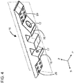
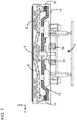
- the adapter 15 is provided with three projection portions 16 arranged along the vehicle longitudinal direction at a lower surface of a beam-shaped body 15a extending along the vehicle longitudinal direction.
- the projection portions 16 on both end sides in the vehicle longitudinal direction each have a trapezoidal cross section, and the projection portion 16 at the center has a rectangular cross section.
- holes 17 each having a stepped shape for holding a head portion of a bolt BT are provided to penetrate in the X direction in the projection portions 16 which are at both end portions in the X direction.
- the adapter 15 is fastened to the lower surface of the side beam 11 in advance by using bolts (not shown) inserted into a plurality of holes 20 ( FIG. 3 ) penetrating in the Z direction in the vicinity of both end portions of the beam-shaped body 15a.
- the bolster beam 13 to be coupled to a truck 2 and the adapter 15 attached to the side beam 11 are combined such that the key 18 is disposed between the projection portions 16 and the projection portion 16 and the key 18 intersect with each other, and two bolts BT ( FIG. 5 ) are inserted through the holes 17 at both sides and screwed into the screw holes 19, respectively.
- two bolts BT FIG. 5
- a bolt (not shown) for fastening the adapter 15 and the side beam 11 is applied with a shear load in addition to a load caused by friction of the contact surfaces, but many bolts (for example, 12 bolts per adapter 15) are used, so that the load received by the respective bolts can be distributed.
- many bolts for example, 12 bolts per adapter 15
- the bolster beam 13 and the adapter 15 can also be fastened by providing coaxial holes penetrating all the projection portions 16 and the keys 18 in the X direction, inserting a single bolt having a length penetrating these holes, and screwing a nut to a penetrating end of the bolt.
- a height position of a center portion of the bolster beam 13 in the vehicle width direction is higher than those at both end portions as shown in a cross sectional view of the truck 2 and the underframe 10 in FIG. 6 , with respect to the underframe structure in the first embodiment.
- the center portion of the bolster beam 13 in the vehicle width direction is support with respect to the truck 2 via an air spring 4, and a center pin 14 provided on a lower surface of the center portion of the bolster beam 13 in the vehicle width direction is coupled to the truck 2.
- joint positions between the adapters 15 and both end portions of the bolster beam 13 in the vehicle width direction can be lowered, so that it is possible to minimize or eliminate a change in a height position of the structure 1 even when the adapter 15 is provided between the side beam 11 and the bolster beam 13.
- the bending rigidity of the bolster beam 13 in the X direction can be improved, so that it is possible to reduce bending deformation of the bolster beam 13 due to vibration in a vehicle vertical direction.
- a height position of a center portion of a floor structure 5 in the vehicle width direction is higher than those at both end portions as shown in a cross sectional view of the truck 2 and the underframe 10 in FIG. 7 , with respect to the underframe structure in the second embodiment.
- a side beam 11 ( FIG. 2 ) attached to a lower surface of the floor structure 5 is coupled to the adapter 15.
- an offset amount between height positions of a connector receiver 21 used for vehicle coupling and the floor structure 5 is reduced, and even when a middle beam is omitted, a load at the time of coupling can be efficiently transmitted to the floor structure 5. Further, it is possible to dispose a wiring/duct 6 in a space between a floor plate 7 and the floor structure 5, or to dispose a damping material or the like for noise reduction. Further, since the bending rigidity of the floor structure 5 in the X direction can be improved, deformation of the vehicle body due to an airtightness load and weight of passengers can be reduced. Further, the configuration of the third embodiment may be combined with the configuration of the first embodiment.
- the structure 1 having an underframe structure shown as a fourth embodiment includes plate members 22A and 22B provided on a connecting portion between the end beam 12 and the side beam 11 as reinforcement members that increase the strength when a coupling load is transmitted to the side beam 11 and the floor structure 5, as shown in a schematic view of a connecting portion of the end beam and the side beam in FIG. 8 , and the present embodiment can be applied to any of the underframe structures of the first to third embodiments.
- the plate member 22A includes a vertical plate 22a and a horizontal plate 22b.
- the vertical plate 22a bent at the center has a trapezoidal shape, which is narrowed as away from the end beam 12, on a distal end portion side, a proximal end portion is welded to the end beam 12, and a bottom edge is welded to the floor structure 5.
- the horizontal plate 22b spaced apart from the floor structure 5 has a trapezoidal shape, which is narrowed as away from the end beam 12, on a distal end portion side, a proximal end portion is welded to the end beam 12, one side edge is welded to the vertical plate 22a, and the other side edge is welded to a side surface of the side beam 11. That is, a cross-sectional shape of the plate member 22A on the distal end portion side becomes smaller as away from the end beam 12.
- the plate member 22B includes a vertical plate 22c and a horizontal plate 22d.
- the vertical plate 22c has a trapezoidal shape, which is narrowed as away from the end beam 12, on a distal end portion side, a proximal end portion is welded to the end beam 12, a bottom edge is welded to the upper surface of the side beam 11, and an upper edge is welded to the center of a lower surface of the horizontal plate 22d.
- the rectangular horizontal plate 22d is bent at the center, and a proximal end portion is welded to the end beam 12. That is, a height of the plate member 22B on the distal end portion side reduces as away from the end beam 12.
- the plate members 22A and 22B increase the strength of the connecting portion between the end beam 12 and the side beam 11, and even when the middle beam is omitted, a load at the time of coupling can be transmitted to the side beam 11 and the floor structure 5 while relaxing the stress. Further, it is sufficient to provide at least one of the plate members 22A and 22B.
- the adapter 15 is attached to the structure 1 by bolt fastening, but it is also possible to attach the adapter 15 to the structure by welding. Further, it is also possible to adopt a configuration in which a member for receiving a load from a yaw damper attached to the truck 2 is attached to the bolster beam 13.
- the invention is not limited to the embodiments described above, and includes various modifications.
- the above-described embodiments have been described in detail for easy understanding of the invention, and the invention is not necessarily limited to one having all the described configurations.
- a part of the configurations of one embodiment can be replaced with the configurations of another embodiment, and the configurations of a certain embodiment can be added to the configurations of another embodiment.
- a part of the configurations of each embodiment may be added to, deleted from, or replaced with other configurations.
Landscapes
- Engineering & Computer Science (AREA)
- Mechanical Engineering (AREA)
- Body Structure For Vehicles (AREA)
- Connection Of Plates (AREA)
Abstract
Description
- The present invention relates to an underframe structure of a rail vehicle and a rail vehicle.
- In general, a vehicle structure (hereinafter, referred to as a structure) is a hexahedral structure composed of an underframe forming a floor surface, side structures disposed at both end portions of the underframe in a width direction thereof, end structures disposed at both end portions of the underframe in a longitudinal direction thereof, and a roof structure disposed on the side structures and the end structures.
- The underframe (hereinafter, also referred to as a underframe structure) includes: side beams provided at both end portions of the underframe in the width direction along the longitudinal direction thereof; end beams each connecting both end portions of the side beams in the longitudinal direction; bolster beams each being provided, along the end beam, at a position away from a longitudinal end portion of the structure by a predetermined distance; a middle beam disposed along the longitudinal direction of the structure to connect the end beams and the bolster beams with the structure.
- A center pin provided along a structure vertical direction on a lower surface of the bolster beam is connected to a truck frame constituting the truck. During acceleration and deceleration of the vehicle, a load in a vehicle front-rear direction is transmitted from the truck to the bolster beam via the center pin.
- On the other hand, from the viewpoint of improving assemblability of a railway vehicle, it is required to facilitate attachment of wirings and ducts attached to the underfloor. In order to facilitate the attachment, it is effective to adopt a structure in which the middle beam is omitted, and to assemble the structure in a state where the bolster beams are attached to the truck. As a truck structure corresponding to a structure in which such a middle beam is omitted,
PTLs 1 and 2 propose a truck including a bolster beam that is fastened only to the side beam using a bolt. -
- PTL 1:
European Patent Application Publication Number 2500231 - PTL 1:
European Patent Application Publication Number 2540592 - When the middle beam is omitted in the underframe structure of the railway vehicle, the load transmitted from the truck to the bolster beam is transmitted only to the side beam, so that the load applied to a connecting portion between the bolster beam and the side beam increases. Further, a load is also transmitted from the end beam to the side beam only at the time of coupling, so that the load applied to the connecting portion between the bolster beam and the side beam increases similarly as described above.
- Therefore, in the truck structure described in
PTLs 1 and 2, a shear load applied to a bolt for attaching the bolster beam to the structure increases when a vehicle body receives a load at the time of pulling or coupling, and thus reliability of a bolt fastening portion may be reduced. - The invention is made in view of the problems in the related art, and an object thereof is to provide a rail vehicle and an underframe structure of a rail vehicle that contributes to improving the assemblability of a vehicle body and has high reliability.
- To solve the above problems, as one representive underframe structure of the invention, the underframe structure of a rail vehicle including a side beam and a bolster beam, and coupled to a truck via the bolster beam includes an adapter attached to the side beam and having a plurality of projection portions arranged along a vehicle longitudinal direction, the bolster beam includes a key, the key is disposed between the projection portions of the adapter, and the key and the projection portions are fastened using a bolt extending in the vehicle longitudinal direction.
- According to the invention, it is possible to provide a rail vehicle and an underframe structure of a rail vehicle that contributes to improving assemblability of a vehicle body and has high reliability.
- Problems, configurations and effects other than the above will be apparent with reference to description of following embodiments.
-
- [
FIG. 1] FIG. 1 is a side view of a railway vehicle including an underframe structure according to a first embodiment. - [
FIG. 2] FIG. 2 is a bottom perspective view of a vehicle structure including the underframe structure according to the first embodiment. - [
FIG. 3] FIG. 3 is an external view of a bolster beam and adapters in the underframe structure according to the first embodiment. - [
FIG. 4] FIG. 4 is an external view of the adapter according to the first embodiment. - [
FIG. 5] FIG. 5 is a cross-sectional view of the adapter according to the first embodiment. - [
FIG. 6] FIG. 6 is a cross-sectional view of an underframe structure and a truck according to a second embodiment. - [
FIG. 7] FIG. 7 is a cross-sectional view of an underframe structure and a truck according to a third embodiment. - [
FIG. 8] FIG. 8 is an external view of a connecting portion of an end beam and a side beam according to a fourth embodiment. - Embodiments disclosed in the invention relate to a structure in which a bolster beam is fastened to a side beam using a bolt. Directions used in the following description are defined as follows . In a structure 1 shown in the drawings, a vehicle longitudinal direction (front-rear direction, rail direction) is set as a X direction, a vehicle width direction (sleeper direction) is set as a Y direction, and a height direction is set as a Z direction. Further, in some cases, the directions are simply referred to as the X direction, the Y direction, and the Z direction.
- A rail vehicle is a vehicle that moves along a laid rail, and includes a railway vehicle, a monorail vehicle, a tram, an automated guideway transit vehicle, and the like. The embodiments of the invention will be described by taking the railway vehicle as a representative example of the rail vehicle.
- As shown in
FIG. 1 , the structure 1 of the railway vehicle including anunderframe 10 shown as a first embodiment inFIGS. 1 to 5 includes theunderframe 10 forming a floor surface,side structures 30 disposed at both end portions of theunderframe 10 in a width direction thereof,end structures 40 disposed at both end portions of theunderframe 10 in a longitudinal direction thereof, and aroof structure 50 disposed on theend structures 40 and theside structures 30. - Further, as shown in
FIG. 1 or2 , theunderframe 10 has a pair ofside beams 11 provided at both end portions of theunderframe 10 in the width direction thereof and extending along the longitudinal direction thereof,end beams 12 each connecting both end portions of theside beams 11 in the vehicle longitudinal direction, andbolster beams 13 each being provided at a position facing atruck frame 3 under theunderframe 10. As shown inFIG. 3 , theunderframe 10 is provided with portions protruding in the Y direction from both end portions of thebolster beam 13 in the vehicle width direction. In the present specification, this protruding portion is referred to as a "key" . In the following embodiments, akey 18 has a rectangular cross section in an X-Z plane, a rectangular cross section in an X-Y plane, and a rectangular cross section in a Y-Z plane. However, at least one of the cross sections may have a shape other than a rectangle. Ascrew hole 19 is provided on a side surface of thekey 18 in the X direction. - Further, on lower surfaces of the side beams 11 (not shown in
FIG. 3 ),adapters 15 each are disposed at a position facing thekey 18. As shown inFIG. 5 , theadapter 15 is provided with threeprojection portions 16 arranged along the vehicle longitudinal direction at a lower surface of a beam-shaped body 15a extending along the vehicle longitudinal direction. As shown inFIG. 5 , theprojection portions 16 on both end sides in the vehicle longitudinal direction each have a trapezoidal cross section, and theprojection portion 16 at the center has a rectangular cross section. As shown inFIGS. 4 and5 ,holes 17 each having a stepped shape for holding a head portion of a bolt BT are provided to penetrate in the X direction in theprojection portions 16 which are at both end portions in the X direction. - The
adapter 15 is fastened to the lower surface of theside beam 11 in advance by using bolts (not shown) inserted into a plurality of holes 20 (FIG. 3 ) penetrating in the Z direction in the vicinity of both end portions of the beam-shaped body 15a. At a time of assembling a truck, thebolster beam 13 to be coupled to atruck 2 and theadapter 15 attached to theside beam 11 are combined such that thekey 18 is disposed between theprojection portions 16 and theprojection portion 16 and thekey 18 intersect with each other, and two bolts BT (FIG. 5 ) are inserted through theholes 17 at both sides and screwed into thescrew holes 19, respectively. By tightening the bolts BT, facing surfaces of theprojection portion 16 and thekey 18 are in close contact with each other, and thebolster beam 13 and theside beam 11 can be coupled via theadapter 15. - Therefore, a part of load transmitted to the connecting portion between the
bolster beam 13 and theside beam 11 at the time of pulling or coupling is applied to the bolts BT for fastening thekey 18 and theadapter 15 of thebolster beam 13 on a traveling direction forward side as a tensile load, and the remaining load is applied to contact surfaces between theprojection portion 16 and thekey 18 on a traveling direction rearward side. Therefore, the tensile load applied to the bolt BT is not excessively large. On the other hand, a bolt (not shown) for fastening theadapter 15 and theside beam 11 is applied with a shear load in addition to a load caused by friction of the contact surfaces, but many bolts (for example, 12 bolts per adapter 15) are used, so that the load received by the respective bolts can be distributed. As described above, according to the present embodiment, it is possible to avoid a concentration of the shear load on the bolts for fastening the connecting portion of thebolster beam 13 and theside beam 11. - Further, the
bolster beam 13 and theadapter 15 can also be fastened by providing coaxial holes penetrating all theprojection portions 16 and thekeys 18 in the X direction, inserting a single bolt having a length penetrating these holes, and screwing a nut to a penetrating end of the bolt. - In the
underframe 10 shown as a second embodiment, a height position of a center portion of thebolster beam 13 in the vehicle width direction is higher than those at both end portions as shown in a cross sectional view of thetruck 2 and theunderframe 10 inFIG. 6 , with respect to the underframe structure in the first embodiment. The center portion of thebolster beam 13 in the vehicle width direction is support with respect to thetruck 2 via anair spring 4, and acenter pin 14 provided on a lower surface of the center portion of thebolster beam 13 in the vehicle width direction is coupled to thetruck 2. - According to the present embodiment, joint positions between the
adapters 15 and both end portions of thebolster beam 13 in the vehicle width direction can be lowered, so that it is possible to minimize or eliminate a change in a height position of the structure 1 even when theadapter 15 is provided between theside beam 11 and thebolster beam 13. Further, the bending rigidity of thebolster beam 13 in the X direction can be improved, so that it is possible to reduce bending deformation of thebolster beam 13 due to vibration in a vehicle vertical direction. - In the
underframe 10 shown as a third embodiment, a height position of a center portion of afloor structure 5 in the vehicle width direction is higher than those at both end portions as shown in a cross sectional view of thetruck 2 and theunderframe 10 inFIG. 7 , with respect to the underframe structure in the second embodiment. A side beam 11 (FIG. 2 ) attached to a lower surface of thefloor structure 5 is coupled to theadapter 15. - According to the present embodiment, an offset amount between height positions of a
connector receiver 21 used for vehicle coupling and thefloor structure 5 is reduced, and even when a middle beam is omitted, a load at the time of coupling can be efficiently transmitted to thefloor structure 5. Further, it is possible to dispose a wiring/duct 6 in a space between a floor plate 7 and thefloor structure 5, or to dispose a damping material or the like for noise reduction. Further, since the bending rigidity of thefloor structure 5 in the X direction can be improved, deformation of the vehicle body due to an airtightness load and weight of passengers can be reduced. Further, the configuration of the third embodiment may be combined with the configuration of the first embodiment. - The structure 1 having an underframe structure shown as a fourth embodiment includes
plate members end beam 12 and theside beam 11 as reinforcement members that increase the strength when a coupling load is transmitted to theside beam 11 and thefloor structure 5, as shown in a schematic view of a connecting portion of the end beam and the side beam inFIG. 8 , and the present embodiment can be applied to any of the underframe structures of the first to third embodiments. - The
plate member 22A includes avertical plate 22a and ahorizontal plate 22b. Thevertical plate 22a bent at the center has a trapezoidal shape, which is narrowed as away from theend beam 12, on a distal end portion side, a proximal end portion is welded to theend beam 12, and a bottom edge is welded to thefloor structure 5. Further, thehorizontal plate 22b spaced apart from thefloor structure 5 has a trapezoidal shape, which is narrowed as away from theend beam 12, on a distal end portion side, a proximal end portion is welded to theend beam 12, one side edge is welded to thevertical plate 22a, and the other side edge is welded to a side surface of theside beam 11. That is, a cross-sectional shape of theplate member 22A on the distal end portion side becomes smaller as away from theend beam 12. - The
plate member 22B includes avertical plate 22c and ahorizontal plate 22d. Thevertical plate 22c has a trapezoidal shape, which is narrowed as away from theend beam 12, on a distal end portion side, a proximal end portion is welded to theend beam 12, a bottom edge is welded to the upper surface of theside beam 11, and an upper edge is welded to the center of a lower surface of thehorizontal plate 22d. Further, the rectangularhorizontal plate 22d is bent at the center, and a proximal end portion is welded to theend beam 12. That is, a height of theplate member 22B on the distal end portion side reduces as away from theend beam 12. - The
plate members end beam 12 and theside beam 11, and even when the middle beam is omitted, a load at the time of coupling can be transmitted to theside beam 11 and thefloor structure 5 while relaxing the stress. Further, it is sufficient to provide at least one of theplate members - In the embodiments described above, the
adapter 15 is attached to the structure 1 by bolt fastening, but it is also possible to attach theadapter 15 to the structure by welding. Further, it is also possible to adopt a configuration in which a member for receiving a load from a yaw damper attached to thetruck 2 is attached to the bolsterbeam 13. - The invention is not limited to the embodiments described above, and includes various modifications. For example, the above-described embodiments have been described in detail for easy understanding of the invention, and the invention is not necessarily limited to one having all the described configurations. Further, a part of the configurations of one embodiment can be replaced with the configurations of another embodiment, and the configurations of a certain embodiment can be added to the configurations of another embodiment. Further, a part of the configurations of each embodiment may be added to, deleted from, or replaced with other configurations.
-
- 1: structure
- 2: truck
- 3: truck frame
- 4: air spring
- 5: floor structure
- 6: wiring/duct
- 7: floor plate
- 10: underframe
- 11: side beam
- 12: end beam
- 13: bolster beam
- 14: center pin
- 15: adapter
- 16: projection portion
- 17: hole
- 18: key
- 19: screw hole
- 20: hole
- 21: connector receiver
- 22A, 22B: plate member
- 30: side structure
- 40: end structure
- 50: roof structure
Claims (6)
- An underframe structure of a rail vehicle, including a side beam and a bolster beam, and connected to a truck via the bolster beam, the underframe structure comprising:an adapter attached to the side beam and having a plurality of projection portions arranged along a vehicle longitudinal direction, whereinthe bolster beam includes a key, andthe key is disposed between the projection portions of the adapter, and the key and the projection portions are fastened using a bolt extending in the vehicle longitudinal direction.
- The underframe structure according to claim 1, wherein
at least one of the projection portions of the adapter has a through hole extending along the vehicle longitudinal direction,
the key has a screw hole, and
the bolt is inserted into the through hole and screwed into the screw hole. - The underframe structure according to claim 1 or 2, wherein
a center portion of the bolster beam in a vehicle width direction is supported with respect to the truck, and the adapter is attached to both end portions of the bolster beam in the vehicle width direction, and
the center portion of the bolster beam is positioned higher than the both end portions of the bolster beam. - The underframe structure according to any one of claims 1 to 3, wherein
the underframe structure includes a floor structure disposed on the side beam, and
a center portion of the floor structure in the vehicle width direction is positioned higher than both end portions of the floor structure in the vehicle width direction. - The underframe structure according to any one of claims 1 to 4, further comprising:
a reinforcement member that reinforces a connecting portion of the side beam and an end beam. - A rail vehicle, comprising:
the underframe structure according to claim 5.
Applications Claiming Priority (1)
| Application Number | Priority Date | Filing Date | Title |
|---|---|---|---|
| PCT/JP2018/037904 WO2020075264A1 (en) | 2018-10-11 | 2018-10-11 | Rail vehicle underframe structure and rail vehicle |
Publications (3)
| Publication Number | Publication Date |
|---|---|
| EP3865368A1 true EP3865368A1 (en) | 2021-08-18 |
| EP3865368A4 EP3865368A4 (en) | 2022-06-15 |
| EP3865368B1 EP3865368B1 (en) | 2022-11-23 |
Family
ID=70165224
Family Applications (1)
| Application Number | Title | Priority Date | Filing Date |
|---|---|---|---|
| EP18933737.1A Active EP3865368B1 (en) | 2018-10-11 | 2018-10-11 | Rail vehicle underframe structure and rail vehicle |
Country Status (3)
| Country | Link |
|---|---|
| EP (1) | EP3865368B1 (en) |
| JP (1) | JP6837182B2 (en) |
| WO (1) | WO2020075264A1 (en) |
Families Citing this family (4)
| Publication number | Priority date | Publication date | Assignee | Title |
|---|---|---|---|---|
| CN111976769B (en) * | 2020-08-20 | 2021-11-26 | 中车大同电力机车有限公司 | Locomotive underframe structure and locomotive with same |
| CN112519817B (en) * | 2020-11-27 | 2024-08-20 | 中铁宝桥集团有限公司 | Vehicle body underframe structure of medium-low speed magnetic levitation vehicle |
| CN113451951B (en) * | 2021-06-24 | 2022-12-09 | 中车株洲电力机车有限公司 | Urban rail vehicle chassis wiring method |
| CN116534068B (en) * | 2023-06-26 | 2025-08-08 | 中车株洲电力机车有限公司 | Rail vehicle body underframe structure and rail vehicle |
Family Cites Families (5)
| Publication number | Priority date | Publication date | Assignee | Title |
|---|---|---|---|---|
| ES2547087T3 (en) | 2011-03-16 | 2015-10-01 | Bombardier Transportation Gmbh | Railway vehicle unit with bearing support |
| ES2547431T3 (en) | 2011-06-29 | 2015-10-06 | Bombardier Transportation Gmbh | Undercarriage for rail vehicle with pneumatic spring device |
| GB2567545B (en) * | 2012-04-17 | 2019-08-14 | Hitachi Ltd | Rail vehicle body structure |
| JP6535757B2 (en) * | 2015-12-17 | 2019-06-26 | 株式会社日立製作所 | Pillow beam and rail vehicle assembly having the same |
| JP6791706B2 (en) * | 2016-09-30 | 2020-11-25 | 株式会社日立製作所 | Rail vehicle structure |
-
2018
- 2018-10-11 EP EP18933737.1A patent/EP3865368B1/en active Active
- 2018-10-11 JP JP2020509547A patent/JP6837182B2/en active Active
- 2018-10-11 WO PCT/JP2018/037904 patent/WO2020075264A1/en not_active Ceased
Also Published As
| Publication number | Publication date |
|---|---|
| EP3865368B1 (en) | 2022-11-23 |
| EP3865368A4 (en) | 2022-06-15 |
| WO2020075264A1 (en) | 2020-04-16 |
| JPWO2020075264A1 (en) | 2021-02-15 |
| JP6837182B2 (en) | 2021-03-03 |
Similar Documents
| Publication | Publication Date | Title |
|---|---|---|
| EP3865368B1 (en) | Rail vehicle underframe structure and rail vehicle | |
| US7841649B2 (en) | Vehicle body structure | |
| US8002064B2 (en) | Frame structure of automotive vehicle | |
| US6416117B1 (en) | Beam connection | |
| US20120097066A1 (en) | Railcar | |
| EP3431357B1 (en) | Vehicle body structure adapted for use in railroad vehicle and provided with wire/pipe module, and method for manufacturing same | |
| EP2204309B1 (en) | Car body structure | |
| KR20210119213A (en) | Body for vehicle | |
| US10549764B2 (en) | Attaching metal fitting, attaching unit, and railcar | |
| CN101674971B (en) | Underframe for automobile | |
| CN106945730A (en) | Vehicle frame structure | |
| US12337880B2 (en) | Railroad vehicle | |
| US20140150688A1 (en) | Railcar | |
| US20120298609A1 (en) | Car equipment protection structure for railcar | |
| US9475506B2 (en) | Rolling stock | |
| CN220391349U (en) | Suspension mounting structure and vehicle | |
| KR102621565B1 (en) | Vehicle under structure for mounting a battery | |
| EP4177129B1 (en) | Railway vehicle including a body bolster srtucture | |
| KR102900541B1 (en) | Connection Structure of Center Pivot and Traction Link Bracket for Railway Vehicle | |
| JP6510215B2 (en) | Railway car | |
| RU2675102C1 (en) | Railway train and construction of carrier plate of car | |
| JP2017165124A (en) | Vertical joist, substructure of truck bed and truck | |
| JP2014080065A (en) | Track system vehicle and manufacturing method thereof |
Legal Events
| Date | Code | Title | Description |
|---|---|---|---|
| STAA | Information on the status of an ep patent application or granted ep patent |
Free format text: STATUS: UNKNOWN |
|
| STAA | Information on the status of an ep patent application or granted ep patent |
Free format text: STATUS: THE INTERNATIONAL PUBLICATION HAS BEEN MADE |
|
| PUAI | Public reference made under article 153(3) epc to a published international application that has entered the european phase |
Free format text: ORIGINAL CODE: 0009012 |
|
| STAA | Information on the status of an ep patent application or granted ep patent |
Free format text: STATUS: REQUEST FOR EXAMINATION WAS MADE |
|
| 17P | Request for examination filed |
Effective date: 20200327 |
|
| AK | Designated contracting states |
Kind code of ref document: A1 Designated state(s): AL AT BE BG CH CY CZ DE DK EE ES FI FR GB GR HR HU IE IS IT LI LT LU LV MC MK MT NL NO PL PT RO RS SE SI SK SM TR |
|
| RIN1 | Information on inventor provided before grant (corrected) |
Inventor name: KIMURA, SOTA Inventor name: KOREISHI, KAZUTO Inventor name: MOCHIDA, TOSHIHIKO |
|
| DAV | Request for validation of the european patent (deleted) | ||
| DAX | Request for extension of the european patent (deleted) | ||
| A4 | Supplementary search report drawn up and despatched |
Effective date: 20220512 |
|
| RIC1 | Information provided on ipc code assigned before grant |
Ipc: B61F 5/14 20060101ALI20220506BHEP Ipc: B61F 5/02 20060101ALI20220506BHEP Ipc: B61F 1/00 20060101AFI20220506BHEP |
|
| GRAP | Despatch of communication of intention to grant a patent |
Free format text: ORIGINAL CODE: EPIDOSNIGR1 |
|
| STAA | Information on the status of an ep patent application or granted ep patent |
Free format text: STATUS: GRANT OF PATENT IS INTENDED |
|
| RIC1 | Information provided on ipc code assigned before grant |
Ipc: B61F 5/14 20060101ALI20220615BHEP Ipc: B61F 5/02 20060101ALI20220615BHEP Ipc: B61F 1/00 20060101AFI20220615BHEP |
|
| INTG | Intention to grant announced |
Effective date: 20220708 |
|
| GRAS | Grant fee paid |
Free format text: ORIGINAL CODE: EPIDOSNIGR3 |
|
| GRAA | (expected) grant |
Free format text: ORIGINAL CODE: 0009210 |
|
| STAA | Information on the status of an ep patent application or granted ep patent |
Free format text: STATUS: THE PATENT HAS BEEN GRANTED |
|
| AK | Designated contracting states |
Kind code of ref document: B1 Designated state(s): AL AT BE BG CH CY CZ DE DK EE ES FI FR GB GR HR HU IE IS IT LI LT LU LV MC MK MT NL NO PL PT RO RS SE SI SK SM TR |
|
| REG | Reference to a national code |
Ref country code: GB Ref legal event code: FG4D |
|
| REG | Reference to a national code |
Ref country code: CH Ref legal event code: EP |
|
| REG | Reference to a national code |
Ref country code: DE Ref legal event code: R096 Ref document number: 602018043516 Country of ref document: DE |
|
| REG | Reference to a national code |
Ref country code: AT Ref legal event code: REF Ref document number: 1532976 Country of ref document: AT Kind code of ref document: T Effective date: 20221215 |
|
| REG | Reference to a national code |
Ref country code: IE Ref legal event code: FG4D |
|
| REG | Reference to a national code |
Ref country code: LT Ref legal event code: MG9D |
|
| REG | Reference to a national code |
Ref country code: NL Ref legal event code: MP Effective date: 20221123 |
|
| REG | Reference to a national code |
Ref country code: AT Ref legal event code: MK05 Ref document number: 1532976 Country of ref document: AT Kind code of ref document: T Effective date: 20221123 |
|
| PG25 | Lapsed in a contracting state [announced via postgrant information from national office to epo] |
Ref country code: SE Free format text: LAPSE BECAUSE OF FAILURE TO SUBMIT A TRANSLATION OF THE DESCRIPTION OR TO PAY THE FEE WITHIN THE PRESCRIBED TIME-LIMIT Effective date: 20221123 Ref country code: PT Free format text: LAPSE BECAUSE OF FAILURE TO SUBMIT A TRANSLATION OF THE DESCRIPTION OR TO PAY THE FEE WITHIN THE PRESCRIBED TIME-LIMIT Effective date: 20230323 Ref country code: NO Free format text: LAPSE BECAUSE OF FAILURE TO SUBMIT A TRANSLATION OF THE DESCRIPTION OR TO PAY THE FEE WITHIN THE PRESCRIBED TIME-LIMIT Effective date: 20230223 Ref country code: LT Free format text: LAPSE BECAUSE OF FAILURE TO SUBMIT A TRANSLATION OF THE DESCRIPTION OR TO PAY THE FEE WITHIN THE PRESCRIBED TIME-LIMIT Effective date: 20221123 Ref country code: FI Free format text: LAPSE BECAUSE OF FAILURE TO SUBMIT A TRANSLATION OF THE DESCRIPTION OR TO PAY THE FEE WITHIN THE PRESCRIBED TIME-LIMIT Effective date: 20221123 Ref country code: ES Free format text: LAPSE BECAUSE OF FAILURE TO SUBMIT A TRANSLATION OF THE DESCRIPTION OR TO PAY THE FEE WITHIN THE PRESCRIBED TIME-LIMIT Effective date: 20221123 Ref country code: AT Free format text: LAPSE BECAUSE OF FAILURE TO SUBMIT A TRANSLATION OF THE DESCRIPTION OR TO PAY THE FEE WITHIN THE PRESCRIBED TIME-LIMIT Effective date: 20221123 |
|
| PG25 | Lapsed in a contracting state [announced via postgrant information from national office to epo] |
Ref country code: RS Free format text: LAPSE BECAUSE OF FAILURE TO SUBMIT A TRANSLATION OF THE DESCRIPTION OR TO PAY THE FEE WITHIN THE PRESCRIBED TIME-LIMIT Effective date: 20221123 Ref country code: PL Free format text: LAPSE BECAUSE OF FAILURE TO SUBMIT A TRANSLATION OF THE DESCRIPTION OR TO PAY THE FEE WITHIN THE PRESCRIBED TIME-LIMIT Effective date: 20221123 Ref country code: LV Free format text: LAPSE BECAUSE OF FAILURE TO SUBMIT A TRANSLATION OF THE DESCRIPTION OR TO PAY THE FEE WITHIN THE PRESCRIBED TIME-LIMIT Effective date: 20221123 Ref country code: IS Free format text: LAPSE BECAUSE OF FAILURE TO SUBMIT A TRANSLATION OF THE DESCRIPTION OR TO PAY THE FEE WITHIN THE PRESCRIBED TIME-LIMIT Effective date: 20230323 Ref country code: HR Free format text: LAPSE BECAUSE OF FAILURE TO SUBMIT A TRANSLATION OF THE DESCRIPTION OR TO PAY THE FEE WITHIN THE PRESCRIBED TIME-LIMIT Effective date: 20221123 Ref country code: GR Free format text: LAPSE BECAUSE OF FAILURE TO SUBMIT A TRANSLATION OF THE DESCRIPTION OR TO PAY THE FEE WITHIN THE PRESCRIBED TIME-LIMIT Effective date: 20230224 |
|
| PG25 | Lapsed in a contracting state [announced via postgrant information from national office to epo] |
Ref country code: NL Free format text: LAPSE BECAUSE OF FAILURE TO SUBMIT A TRANSLATION OF THE DESCRIPTION OR TO PAY THE FEE WITHIN THE PRESCRIBED TIME-LIMIT Effective date: 20221123 |
|
| PG25 | Lapsed in a contracting state [announced via postgrant information from national office to epo] |
Ref country code: SM Free format text: LAPSE BECAUSE OF FAILURE TO SUBMIT A TRANSLATION OF THE DESCRIPTION OR TO PAY THE FEE WITHIN THE PRESCRIBED TIME-LIMIT Effective date: 20221123 Ref country code: RO Free format text: LAPSE BECAUSE OF FAILURE TO SUBMIT A TRANSLATION OF THE DESCRIPTION OR TO PAY THE FEE WITHIN THE PRESCRIBED TIME-LIMIT Effective date: 20221123 Ref country code: EE Free format text: LAPSE BECAUSE OF FAILURE TO SUBMIT A TRANSLATION OF THE DESCRIPTION OR TO PAY THE FEE WITHIN THE PRESCRIBED TIME-LIMIT Effective date: 20221123 Ref country code: DK Free format text: LAPSE BECAUSE OF FAILURE TO SUBMIT A TRANSLATION OF THE DESCRIPTION OR TO PAY THE FEE WITHIN THE PRESCRIBED TIME-LIMIT Effective date: 20221123 Ref country code: CZ Free format text: LAPSE BECAUSE OF FAILURE TO SUBMIT A TRANSLATION OF THE DESCRIPTION OR TO PAY THE FEE WITHIN THE PRESCRIBED TIME-LIMIT Effective date: 20221123 |
|
| REG | Reference to a national code |
Ref country code: DE Ref legal event code: R097 Ref document number: 602018043516 Country of ref document: DE |
|
| PG25 | Lapsed in a contracting state [announced via postgrant information from national office to epo] |
Ref country code: SK Free format text: LAPSE BECAUSE OF FAILURE TO SUBMIT A TRANSLATION OF THE DESCRIPTION OR TO PAY THE FEE WITHIN THE PRESCRIBED TIME-LIMIT Effective date: 20221123 Ref country code: AL Free format text: LAPSE BECAUSE OF FAILURE TO SUBMIT A TRANSLATION OF THE DESCRIPTION OR TO PAY THE FEE WITHIN THE PRESCRIBED TIME-LIMIT Effective date: 20221123 |
|
| PLBE | No opposition filed within time limit |
Free format text: ORIGINAL CODE: 0009261 |
|
| STAA | Information on the status of an ep patent application or granted ep patent |
Free format text: STATUS: NO OPPOSITION FILED WITHIN TIME LIMIT |
|
| 26N | No opposition filed |
Effective date: 20230824 |
|
| PG25 | Lapsed in a contracting state [announced via postgrant information from national office to epo] |
Ref country code: SI Free format text: LAPSE BECAUSE OF FAILURE TO SUBMIT A TRANSLATION OF THE DESCRIPTION OR TO PAY THE FEE WITHIN THE PRESCRIBED TIME-LIMIT Effective date: 20221123 |
|
| PG25 | Lapsed in a contracting state [announced via postgrant information from national office to epo] |
Ref country code: IT Free format text: LAPSE BECAUSE OF FAILURE TO SUBMIT A TRANSLATION OF THE DESCRIPTION OR TO PAY THE FEE WITHIN THE PRESCRIBED TIME-LIMIT Effective date: 20221123 Ref country code: MC Free format text: LAPSE BECAUSE OF FAILURE TO SUBMIT A TRANSLATION OF THE DESCRIPTION OR TO PAY THE FEE WITHIN THE PRESCRIBED TIME-LIMIT Effective date: 20221123 |
|
| REG | Reference to a national code |
Ref country code: CH Ref legal event code: PL |
|
| REG | Reference to a national code |
Ref country code: BE Ref legal event code: MM Effective date: 20231031 |
|
| PG25 | Lapsed in a contracting state [announced via postgrant information from national office to epo] |
Ref country code: LU Free format text: LAPSE BECAUSE OF NON-PAYMENT OF DUE FEES Effective date: 20231011 |
|
| GBPC | Gb: european patent ceased through non-payment of renewal fee |
Effective date: 20231011 |
|
| PG25 | Lapsed in a contracting state [announced via postgrant information from national office to epo] |
Ref country code: LU Free format text: LAPSE BECAUSE OF NON-PAYMENT OF DUE FEES Effective date: 20231011 |
|
| PG25 | Lapsed in a contracting state [announced via postgrant information from national office to epo] |
Ref country code: GB Free format text: LAPSE BECAUSE OF NON-PAYMENT OF DUE FEES Effective date: 20231011 |
|
| PG25 | Lapsed in a contracting state [announced via postgrant information from national office to epo] |
Ref country code: CH Free format text: LAPSE BECAUSE OF NON-PAYMENT OF DUE FEES Effective date: 20231031 |
|
| PG25 | Lapsed in a contracting state [announced via postgrant information from national office to epo] |
Ref country code: GB Free format text: LAPSE BECAUSE OF NON-PAYMENT OF DUE FEES Effective date: 20231011 Ref country code: CH Free format text: LAPSE BECAUSE OF NON-PAYMENT OF DUE FEES Effective date: 20231031 |
|
| PG25 | Lapsed in a contracting state [announced via postgrant information from national office to epo] |
Ref country code: BE Free format text: LAPSE BECAUSE OF NON-PAYMENT OF DUE FEES Effective date: 20231031 |
|
| PG25 | Lapsed in a contracting state [announced via postgrant information from national office to epo] |
Ref country code: IE Free format text: LAPSE BECAUSE OF NON-PAYMENT OF DUE FEES Effective date: 20231011 |
|
| PG25 | Lapsed in a contracting state [announced via postgrant information from national office to epo] |
Ref country code: IE Free format text: LAPSE BECAUSE OF NON-PAYMENT OF DUE FEES Effective date: 20231011 |
|
| PG25 | Lapsed in a contracting state [announced via postgrant information from national office to epo] |
Ref country code: BG Free format text: LAPSE BECAUSE OF FAILURE TO SUBMIT A TRANSLATION OF THE DESCRIPTION OR TO PAY THE FEE WITHIN THE PRESCRIBED TIME-LIMIT Effective date: 20221123 |
|
| PG25 | Lapsed in a contracting state [announced via postgrant information from national office to epo] |
Ref country code: BG Free format text: LAPSE BECAUSE OF FAILURE TO SUBMIT A TRANSLATION OF THE DESCRIPTION OR TO PAY THE FEE WITHIN THE PRESCRIBED TIME-LIMIT Effective date: 20221123 |
|
| PG25 | Lapsed in a contracting state [announced via postgrant information from national office to epo] |
Ref country code: CY Free format text: LAPSE BECAUSE OF FAILURE TO SUBMIT A TRANSLATION OF THE DESCRIPTION OR TO PAY THE FEE WITHIN THE PRESCRIBED TIME-LIMIT; INVALID AB INITIO Effective date: 20181011 |
|
| PG25 | Lapsed in a contracting state [announced via postgrant information from national office to epo] |
Ref country code: HU Free format text: LAPSE BECAUSE OF FAILURE TO SUBMIT A TRANSLATION OF THE DESCRIPTION OR TO PAY THE FEE WITHIN THE PRESCRIBED TIME-LIMIT; INVALID AB INITIO Effective date: 20181011 |
|
| PGFP | Annual fee paid to national office [announced via postgrant information from national office to epo] |
Ref country code: FR Payment date: 20250924 Year of fee payment: 8 |
|
| PG25 | Lapsed in a contracting state [announced via postgrant information from national office to epo] |
Ref country code: TR Free format text: LAPSE BECAUSE OF FAILURE TO SUBMIT A TRANSLATION OF THE DESCRIPTION OR TO PAY THE FEE WITHIN THE PRESCRIBED TIME-LIMIT Effective date: 20221123 |
|
| PGFP | Annual fee paid to national office [announced via postgrant information from national office to epo] |
Ref country code: DE Payment date: 20250923 Year of fee payment: 8 |