EP3865328A1 - Motoreducteur de traction pour vehicule et procede d'assemblage - Google Patents
Motoreducteur de traction pour vehicule et procede d'assemblage Download PDFInfo
- Publication number
- EP3865328A1 EP3865328A1 EP21156808.4A EP21156808A EP3865328A1 EP 3865328 A1 EP3865328 A1 EP 3865328A1 EP 21156808 A EP21156808 A EP 21156808A EP 3865328 A1 EP3865328 A1 EP 3865328A1
- Authority
- EP
- European Patent Office
- Prior art keywords
- rotor
- housing
- casing
- machine
- primary
- Prior art date
- Legal status (The legal status is an assumption and is not a legal conclusion. Google has not performed a legal analysis and makes no representation as to the accuracy of the status listed.)
- Granted
Links
Images


Classifications
-
- B—PERFORMING OPERATIONS; TRANSPORTING
- B60—VEHICLES IN GENERAL
- B60K—ARRANGEMENT OR MOUNTING OF PROPULSION UNITS OR OF TRANSMISSIONS IN VEHICLES; ARRANGEMENT OR MOUNTING OF PLURAL DIVERSE PRIME-MOVERS IN VEHICLES; AUXILIARY DRIVES FOR VEHICLES; INSTRUMENTATION OR DASHBOARDS FOR VEHICLES; ARRANGEMENTS IN CONNECTION WITH COOLING, AIR INTAKE, GAS EXHAUST OR FUEL SUPPLY OF PROPULSION UNITS IN VEHICLES
- B60K1/00—Arrangement or mounting of electrical propulsion units
-
- B—PERFORMING OPERATIONS; TRANSPORTING
- B60—VEHICLES IN GENERAL
- B60K—ARRANGEMENT OR MOUNTING OF PROPULSION UNITS OR OF TRANSMISSIONS IN VEHICLES; ARRANGEMENT OR MOUNTING OF PLURAL DIVERSE PRIME-MOVERS IN VEHICLES; AUXILIARY DRIVES FOR VEHICLES; INSTRUMENTATION OR DASHBOARDS FOR VEHICLES; ARRANGEMENTS IN CONNECTION WITH COOLING, AIR INTAKE, GAS EXHAUST OR FUEL SUPPLY OF PROPULSION UNITS IN VEHICLES
- B60K1/00—Arrangement or mounting of electrical propulsion units
- B60K2001/001—Arrangement or mounting of electrical propulsion units one motor mounted on a propulsion axle for rotating right and left wheels of this axle
Definitions
- the present invention relates to vehicle geared motors.
- a traction motor for a road vehicle grouping together in a casing in several elements, an electric machine composed of a stator and a rotor rotating in bearings supported by the casing, a drive toothing primary carried by the rotor shaft, and a secondary toothing transmitting the movement of the primary toothing on a differential.
- Geared motors used in electric or hybrid vehicles include an electric machine driving the input shaft of a speed reducer ensuring the reduction of the movement of the electric machine transmitted to the kinematic chain of the vehicle in the direction of the wheels thereof. this.
- stator and the rotor of the electric machine, as well as the drive shaft of the reduction gear are housed in a housing.
- the assembled rotor usually consists of a shaft, as well as a set of windings. It is extended by the input shaft of the reduction gear, carrying a primary toothing, driving reduction gears. The assembly is closed by added casing elements.
- the rotor is introduced axially into the housing with its bearings, which find their place in rolling bearings provided in the housings.
- the drive teeth, the rotor, or the bearings may strike the stator or parts of the casing when it is inserted, with a risk of irreversible degradation of these various elements. There is therefore an essential need to ensure the protection of the components of the geared motor and of the casing elements during assembly.
- the object of the present invention is to facilitate the assembly of a geared motor, while ensuring the protection of its components against impacts.
- one of its casing elements has a radial projection approaching the primary teeth over part of its circumference.
- the radial projection has an opening freeing up sufficient space to accommodate the secondary teeth.
- the radial projection constitutes a cylindrical guide bearing surface for a removable protection element, covering the primary teeth when the rotor is introduced into the housing element.
- the rotor is inserted into the machine housing with its bearings, capped with the removable protector.
- This protector ensures the centering of the rotor in the machine casing, being guided along the cylindrical surface of the radial advance.
- the figures 1 and 2 show a geared motor 1, without its mechanism housing 2.
- This is a traction gear motor for a vehicle. It groups together in a casing in several elements 2, 3, 4, an electric machine composed of a stator and a rotor, which rotates in bearings supported by the casing.
- the housing also contains a primary drive toothing 12 carried by the shaft 11 of the rotor 5, and a secondary toothing 15 transmitting the movement of the primary toothing 12 on a differential 16.
- On the figure 1 we see the seam plane of the casing of the electric machine, (or casing machine 2).
- the surface 2c corresponds to a section of the casing at the level of the cylindrical centering surface 17 of a protector 14, around the teeth 12 of the rotor shaft 11.
- the centering surface 17 does not extend over 360 °, to allow the teeth 15 of the secondary shaft to pass.
- the section plane also reveals part of the differential 16.
- the figure 2 is an open side view of the geared motor 1.
- the internal profile of the machine housing 2, the guide surface 17, as well as the bearings 18, 19, of the rotor shaft 11 and of the secondary shaft can be seen.
- the rotor 6 rotates in two bearings 7, 8, which are supported by housings or bearings 9, 10, formed in the mass of the machine casing 2 and of the closing casing 4.
- the rotor shaft 11 extends to the body. exterior of the first bearing 7. It carries the primary drive teeth 12.
- the teeth 12 can be made integral with the shaft 11 of the rotor by splines and / or by smooth shrinking over part of its length. It transmits the torque generated on the rotor, on the secondary line (toothing 15), then on the differential 16. Its axial immobilization on the shaft 11 is provided by a clip 13.
- a plate 21 retaining the outer ring 7a of the first bearing 7 on the machine housing 2.
- the bearings 9, 10 of the bearings 7, 8 extend over 360 in the machine and closing casings 2, 4.
- the machine casing 2 has a radial projection 2a, approaching the primary toothing 12 on part of its circumference.
- This radial projection 2a has in its lower part an opening 2b, which frees up sufficient space to accommodate the secondary teeth 15.
- the radial projection 2a is thus open over approximately a quarter of its circumference. It corresponds to the cylindrical guide surface 17, identified on a figure 1 .
- the means proposed to avoid these risks is to use the removable protection element (or removable protector 14), which is engaged on the end of the rotor shaft 11, before the machine is introduced into its housing. 2.
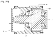
- FIGS. 5A to 5D illustrate the assembly of the geared motor, with the help of the protector 14.
- the projection 2a constitutes a cylindrical guide bearing surface 17 for this protector 14, which covers the primary teeth 12 when the rotor 6 is introduced into the machine housing 2 ( figures 5A, 5B ).
- Protector 14 can then be removed.
- the assembly continues by closing the machine housing 2 by the closing housing 4 on its right ( figure 5C ), and by the mechanism housing 3 on its left ( figure 5D ).
- the proposed architecture has particularities compared to known geared motors, because several components are integrated, in particular the stator 5, which is mounted and fixed on the machine casing 2, to constitute a first sub-assembly of the geared motor 1.
- the rotor 6 can thus be introduced into the machine casing 2 with its bearings 7, 8, while being capped with its protector 14.
- the protector 14 ensures the centering of the rotor 6 in the machine casing 2 by being guided along the cylindrical surface 17 of the 'radial advance 2a.
- the bearings 7, 8 and the teeth 12 are assembled on the rotor, to form a second sub-assembly. Its introduction into the first takes place smoothly, thanks to the protector 14, which is guided by the surface 17 during this operation. Finally, the recess 2b over part of the circumference of the radial projection 2a of the machine housing, frees up sufficient space to accommodate the teeth 15 of the secondary line.
- the protector 14 is an assembly tool, which plays an essential role in protecting the primary teeth 12 against impacts during assembly, by guiding the rotor on the bearing surface of the advance 2a machined in the machine housing. It is centered on the rotor by the cylindrical seat 17, and is positioned axially in abutment on the end of the rotor shaft 11. The centering is not done over its entire periphery, because the housing must allow the passage of the rotor. teeth of the secondary shaft. This does not affect the quality of the centering between the guard and the machine housing.
- the protector 14 can be removed. At this stage, the casing is still open on its left and on its right. It is also possible to screw the retaining plate 21 of the bearing 7 on the machine housing 2, before fitting the closing housing 4. The final stages of the assembly are the assembly of the closing housing 4, and the mechanism housing. 3.
- the main advantage of the proposed geared motor is the ease and reliability of its assembly, thanks to the removable protector 14, and to the arrangement of the casing produced at the level of the radial projection 2a of the machine casing.
- the protector is removed before closing the assembly: the arrangements are limited to providing the centering surfaces on the teeth, and on the machine housing.
- the solution is therefore easy to implement.
- the quality of the centering is excellent, because the chain of centering dimensions between the rotor and the machine housing is direct thanks to the protector.
Landscapes
- Engineering & Computer Science (AREA)
- Chemical & Material Sciences (AREA)
- Combustion & Propulsion (AREA)
- Transportation (AREA)
- Mechanical Engineering (AREA)
- Connection Of Motors, Electrical Generators, Mechanical Devices, And The Like (AREA)
Abstract
Description
- La présente invention se rapporte aux motoréducteurs de véhicule.
- Plus précisément, elle a pour objet un motoréducteur de traction pour véhicule routier, regroupant dans un carter en plusieurs éléments, une machine électrique composée d'un stator et d'un rotor tournant dans des roulements supportés par le carter, une denture d'entraînement primaire portée par l'arbre du rotor, et une denture secondaire transmettant le mouvement de la denture primaire sur un différentiel.
- Elle a également pour objet le procédé d'assemblage d'un tel motoréducteur.
- Les motoréducteurs utilisés dans les véhicules électriques ou hybrides, comprennent une machine électrique entraînant l'arbre d'entrée d'un réducteur de vitesses assurant la démultiplication du mouvement de la machine électrique transmis à la chaîne cinématique du véhicule en direction des roues de celui-ci.
- Selon une disposition habituelle, le stator et le rotor de la machine électrique, ainsi que l'arbre d'entraînement du réducteur sont logés dans un carter. Le rotor assemblé est généralement composé d'un arbre, ainsi que d'un ensemble de bobinages. Il se prolonge par l'arbre d'entrée du réducteur, portant une denture primaire, entraînant des engrenages de réduction. L'ensemble est fermé par des éléments de carters rapportés.
- Lors de l'assemblage, le rotor est introduit axialement dans le carter avec ses roulements, qui trouvent leur place dans des paliers de roulement prévus dans les carters. En l'absence de précautions particulières, la denture d'entraînement, le rotor, ou les roulements, peuvent heurter le stator ou des parties du carter lors de son introduction, avec un risque de dégradation irréversible de ces différents éléments. Il existe donc un besoin essentiel d'assurer la protection des composants du motoréducteur et des éléments de carter lors de l'assemblage.
- La présente invention a pour but de faciliter l'assemblage d'un motoréducteur, tout en assurant la protection de ses composants contre les chocs.
- Dans ce but, un de ses éléments de carter présente une avancée radiale se rapprochant de la denture primaire sur une partie de sa circonférence.
- De préférence, l'avancée radiale présente une ouverture libérant un espace suffisant pour loger la denture secondaire.
- Selon une autre caractéristique, l'avancée radiale constitue une portée cylindrique de guidage pour un élément de protection amovible, coiffant la denture primaire lors de l'introduction du rotor dans l'élément de carter.
- Lors de l'assemblage, le rotor est introduit dans le carter machine avec ses roulements, coiffé du protecteur amovible.
- Ce protecteur assure le centrage du rotor dans le carter machine, en étant guidé le long de la portée cylindrique de l'avancée radiale.
- La présente invention sera mieux comprise à la lecture de la description suivante d'un mode de réalisation non limitatif de celle-ci, en se reportant aux dessins annexés.
- [
fig.1 ] montre l'architecture générale d'un motoréducteur 1 conforme à l'invention. - [
fig.2 ] également. - [
fig.3 ] est un schéma simplifié du même motoréducteur. - [
fig.3A ] est une coupe selon A-A de lafigure 3 . - [
fig.4A ] met en évidence les risques de heurts lors de son assemblage. - [
fig.4B ] également. - [
fig.4C ] également. - [
fig.5A ] montre une étape d'assemblage du motoréducteur avec son dispositif de protection. - [
fig.5B ] également. - [
fig.5C ] montre une étape de fermeture du carter. - [
fig.5D ] également. - Les
figures 1 et 2 montrent un motoréducteur 1, sans son carter de mécanisme 2. Il s'agit d'un motoréducteur de traction pour véhicule. Il regroupe dans un carter en plusieurs éléments 2, 3, 4, une machine électrique composée d'un stator et d'un rotor, qui tourne dans des roulements supportés par le carter. Le carter renferme également une denture d'entraînement primaire 12 portée par l'arbre 11 du rotor 5, et une denture secondaire 15 transmettant le mouvement de la denture primaire 12 sur un différentiel 16. Sur lafigure 1 , on voit le plan de couture du carter de la machine électrique, (ou carter machine 2). La surface 2c correspond à une coupe du carter au niveau de la surface de centrage 17 cylindrique d'un protecteur 14, autour de la denture 12 de l'arbre rotor 11. La surface de centrage 17 ne s'étend pas sur 360°, pour laisser passer la denture 15 de l'arbre secondaire. Le plan de coupe laisse également apparaître une partie du différentiel 16. - La
figure 2 est une vue latérale, ouverte du motoréducteur 1. On voit le profil intérieur du carter machine 2, la surface de guidage 17, ainsi que les paliers 18, 19, de l'arbre de rotor 11, et de l'arbre secondaire. - Les schémas simplifiés suivants illustrent l'architecture du même motoréducteur et son assemblage. Le carter complet comporte trois parties :
- un carter machine 2 supportant le stator 5 de la machine électrique, et un roulement 7 du rotor 6,
- un carter de mécanisme 3 coiffant le carter machine 2 autour des dentures primaire 12 et secondaire 15, et
- un carter de fermeture 4 sur le rotor 6, supportant un des roulements 8 de celui-ci.
- Le rotor 6 tourne dans deux roulements 7, 8, qui sont supportés par des logements ou paliers 9, 10, formés dans la masse du carter machine 2 et du carter de fermeture 4. L'arbre du rotor 11 s'étend à l'extérieur du premier roulement 7. Il porte la denture d'entraînement primaire 12. La denture 12 peut être rendue solidaire de l'arbre 11 du rotor par des cannelures et /ou par un frettage lisse sur une partie de sa longueur. Elle transmet le couple généré sur le rotor, sur la ligne secondaire (denture 15), puis sur le différentiel 16. Son immobilisation axiale sur l'arbre 11, est assurée par un clip 13. On voit également sur le schéma, une plaque 21 retenant la bague extérieure 7a du premier roulement 7 sur le carter machine 2.
- Les paliers 9, 10 des roulements 7, 8 s'étendent sur 360 dans les carters machine et de fermeture 2, 4. A gauche du premier roulement 7, le carter machine 2 présente une avancée radiale 2a, se rapprochant de la denture primaire 12 sur une partie de sa circonférence. Cette avancée radiale 2a présente dans sa partie inférieure, une ouverture 2b, qui libère un espace suffisant pour loger la denture secondaire 15.
- Sur la coupe 3A de la
figure 3 , on retrouve l'arbre de rotor 11, sa denture 12, un espace libre, et le carter machine 2, au niveau de l'avancée radiale 2a. L'avancée 2a du carter mécanisme s'étend approximativement sur les trois quarts de sa circonférence, en couvrant par exemple autour de 230°. - Dans le mode de réalisation non limitatif illustré par les figures, l'avancée radiale 2a est ainsi ouverte sur environ un quart de sa circonférence. Elle correspond à la portée de guidage cylindrique 17, identifiée sur a
figure 1 . - Les
figures 4A à 4C mettent en évidence, comment un défaut d'axialité ou l'inclinaison du rotor 6 par rapport au carter machine 2, peut se traduire lors de l'assemblage par des chocs à plusieurs niveaux : - entre le rotor 6 et le stator 5(
figure 4A ), - entre le premier roulement 7 et l'entrée de son palier 9 (
figure 4B ), ou - entre la denture 12 et l'avancée 2a du carter machine 2 (
figure 4C ). - Le moyen proposé pour éviter ces risques, est d'utiliser l'élément de protection amovible (ou protecteur amovible 14), qui est engagé sur l'extrémité de l'arbre de rotor 11, avant l'introduction de la machine dans son carter 2.
- Les
figures 5A à 5D , illustrent le montage du motoréducteur, avec l'aide du protecteur 14. L'avancée 2a constitue une portée cylindrique de guidage 17 pour ce protecteur 14, qui coiffe la denture primaire 12 lors de l'introduction du rotor 6 dans le carter machine 2 (figures 5A, 5B ). Le protecteur 14 peut ensuite être retiré. L'assemblage se poursuit par la fermeture du carter machine 2 par le carter de fermeture 4 sur sa droite (figure 5C ), et par le carter de mécanisme 3 sur sa gauche (figure 5D ). - L'architecture proposée présente des particularités par rapport aux motoréducteurs connus, car plusieurs composants sont intégrés, en particulier le stator 5, qui est monté et fixé sur le carter machine 2, pour constituer un premier sous-ensemble du motoréducteur 1. Le rotor 6 peut ainsi être introduit dans le carter machine 2 avec ses roulements 7, 8, en étant coiffé de son protecteur 14. le protecteur 14 assure le centrage du rotor 6 dans le carter machine 2 en étant guidé le long de la portée cylindrique 17 de l'avancée radiale 2a.
- Les roulements 7, 8 et la denture 12, sont assemblés sur le rotor, pour constituer un deuxième sous ensemble. Son introduction dans le premier s'effectue sans heurts, grâce au protecteur 14, qui est guidé par la surface 17 lors de cette opération. Enfin, l'évidement 2b sur une partie de la circonférence de l'avancée radiale 2a du carter machine, libère un espace suffisant pour loger la denture 15 de la ligne secondaire.
- Le protecteur 14 est un outil de montage, qui joue un rôle essentiel pour protéger la denture primaire 12 contre les chocs lors de l'assemblage, en guidant le rotor sur la portée de l'avancée 2a usinée dans le carter machine. Il est centré sur le rotor par la portée cylindrique 17, et se positionne axialement en butée sur l'extrémité de l'arbre de rotor 11. Le centrage ne se fait pas sur toute sa périphérie, car le carter doit permettre le passage de la denture de l'arbre secondaire. Cela n'affecte pas la qualité du centrage, entre le protecteur et le carter machine.
- Lorsque le rotor est positionné dans le carter machine, on peut enlever le protecteur 14. A ce stade, le carter est encore ouvert sur sa gauche et sur sa droite. On peut aussi visser la plaque de retenue 21 du roulement 7 sur le carter machine 2, avant la mise en place du carter de fermeture 4. Les dernières étapes de l'assemblage, sont le montage du carter de fermeture 4, et du carter mécanisme 3.
- Le principal intérêt du motoréducteur proposé, est la facilité et la fiabilité de son assemblage, grâce au protecteur amovible 14, et à l'aménagement du carter réalisé au niveau de l'avancée radiale 2a du carter machine. L'impact est faible sur le produit, étant donné que le protecteur est retiré avant de fermer l'ensemble : les aménagements se limitent à prévoir les surfaces de centrage sur la denture, et sur le carter machine. La solution est donc facile à mettre en place. De plus, la qualité du centrage est excellente, car la chaîne de cotes de centrage entre le rotor et le carter machine est directe grâce au protecteur.
Claims (10)
- Motoréducteur de traction (1) pour véhicule regroupant dans un carter en plusieurs éléments (2, 3, 4) une machine électrique composée d'un stator et d'un rotor (6) tournant dans des roulements supportés (7, 8) par le carter, une denture d'entraînement primaire (12) portée par l'arbre (11) du rotor (5), et une denture secondaire (15) transmettant le mouvement de la denture primaire sur un différentiel (16), caractérisé en ce qu'un des élément de carter (2) présente une avancée radiale (2a) se rapprochant de la denture primaire (12) sur une partie de sa circonférence.
- Motoréducteur selon la revendication 1, caractérisé en ce l'avancée radiale (2a) de l'élément de carter (2) présente une ouverture (2b) libérant un espace suffisant pour loger la denture secondaire (15).
- Motoréducteur selon la revendication 1 ou 2, caractérisé en ce que l'avancée radiale (2a) constitue une portée cylindrique de guidage (17) pour élément de protection amovible (14) coiffant la denture primaire (12), lors de l'introduction du rotor (6) dans l'élément de carter (2).
- Motoréducteur selon la revendication 2, caractérisé en ce que l'avancée radiale (2a) est ouverte sur environ un quart de sa circonférence.
- Motoréducteur selon l'une des revendications précédentes, caractérisé en ce qu'il comprend un carter machine (2) supportant le stator (5) de la machine électrique, et un roulement (7) du rotor (6).
- Motoréducteur selon la revendication 5, caractérisé en ce qu'il comprend un carter de mécanisme (3) se coiffant le carter machine (2) autour des dentures primaire (12) et secondaire (15).
- Motoréducteur selon la revendication 5 ou 6, caractérisé en ce qu'il comprend un carter de fermeture (4) sur le rotor (6), supportant un des roulements (8) de celui-ci.
- Procédé d'assemblage d'un motoréducteur selon l'une des revendications 3 à 6, caractérisé en ce que le rotor (6) est introduit dans le carter machine (2) avec ses roulements (7, 8), et en étant coiffé de son protecteur (14).
- Procédé d'assemblage selon la revendication 8, caractérisé en ce que le protecteur (14) assure le centrage du rotor (6) dans le carter machine (2) en étant guidé le long de la portée cylindrique (17) de l'avancée radiale (2a).
- Procédé d'assemblage selon la revendication 8 ou 9, caractérisé en ce qu'on visse une plaque de retenue (21) d'un (7) sur le carter machine (2) avant la mise en place du carter de fermeture (4) sur celui-ci.
Applications Claiming Priority (1)
| Application Number | Priority Date | Filing Date | Title |
|---|---|---|---|
| FR2001430A FR3107213B1 (fr) | 2020-02-13 | 2020-02-13 | Motoreducteur de traction pour vehicule et procede d’assemblage |
Publications (2)
| Publication Number | Publication Date |
|---|---|
| EP3865328A1 true EP3865328A1 (fr) | 2021-08-18 |
| EP3865328B1 EP3865328B1 (fr) | 2023-01-04 |
Family
ID=70295417
Family Applications (1)
| Application Number | Title | Priority Date | Filing Date |
|---|---|---|---|
| EP21156808.4A Active EP3865328B1 (fr) | 2020-02-13 | 2021-02-12 | Motoreducteur de traction pour vehicule et procede d'assemblage correspondant |
Country Status (2)
| Country | Link |
|---|---|
| EP (1) | EP3865328B1 (fr) |
| FR (1) | FR3107213B1 (fr) |
Citations (3)
| Publication number | Priority date | Publication date | Assignee | Title |
|---|---|---|---|---|
| US5832789A (en) * | 1995-12-27 | 1998-11-10 | Aisin Aw Co., Ltd. | Drive unit for an electric vehicle |
| US20030037976A1 (en) * | 2001-03-14 | 2003-02-27 | Bowen Thomas C. | Electric drive motor axle with integrated reduction and differential gearset |
| US20040130224A1 (en) * | 2002-11-28 | 2004-07-08 | Seiichi Mogi | Motor drive unit |
-
2020
- 2020-02-13 FR FR2001430A patent/FR3107213B1/fr not_active Expired - Fee Related
-
2021
- 2021-02-12 EP EP21156808.4A patent/EP3865328B1/fr active Active
Patent Citations (3)
| Publication number | Priority date | Publication date | Assignee | Title |
|---|---|---|---|---|
| US5832789A (en) * | 1995-12-27 | 1998-11-10 | Aisin Aw Co., Ltd. | Drive unit for an electric vehicle |
| US20030037976A1 (en) * | 2001-03-14 | 2003-02-27 | Bowen Thomas C. | Electric drive motor axle with integrated reduction and differential gearset |
| US20040130224A1 (en) * | 2002-11-28 | 2004-07-08 | Seiichi Mogi | Motor drive unit |
Also Published As
| Publication number | Publication date |
|---|---|
| FR3107213B1 (fr) | 2022-05-06 |
| FR3107213A1 (fr) | 2021-08-20 |
| EP3865328B1 (fr) | 2023-01-04 |
Similar Documents
| Publication | Publication Date | Title |
|---|---|---|
| FR3003813A1 (fr) | Transmission pour un essieu pouvant etre entraine electriquement d'un vehicule automobile | |
| EP3298304A1 (fr) | Transmission, ainsi qu'un engin roulant equipe d'une telle transmission | |
| WO2013030478A1 (fr) | Dispositif de liaison d'une colonne de direction avec un boitier de direction. | |
| EP2783062B1 (fr) | Actionneur électrique tubulaire d'entraînement pour un écran domotique, procédé d'assemblage d'un tel actionneur et installation comprenant un tel actionneur | |
| EP1825944A1 (fr) | Mandrin porte-outil pour l'équipement d'une machine tournante, muni de moyens de verrouillage radial et axial séquencés | |
| FR2927682A1 (fr) | Carter pour boite de vitesses d'un vehicule. | |
| EP1957734B1 (fr) | Verrou debrayable pour un mecanisme de serrure automobile | |
| WO2015144528A1 (fr) | Moyeu motorisé pour un véhicule à traction électrique | |
| EP3865328B1 (fr) | Motoreducteur de traction pour vehicule et procede d'assemblage correspondant | |
| EP3465884B1 (fr) | Enveloppe d'une machine electrique avec gaine de refroidissement | |
| FR3000775A1 (fr) | Boite de vitesses pour engin automoteur, tel que tondeuse a gazon | |
| EP3697195B1 (fr) | Boitier de transmission et engin roulant equipe d'un tel boitier | |
| FR3036450A1 (fr) | Transmission pour engin roulant a conducteur de preference marchant et engin roulant equipe d'une telle transmission | |
| FR2895762A1 (fr) | Verrou debrayable pour un mecanisme de serrure automobile | |
| FR2992367A1 (fr) | Dispositif de demarrage et procede de montage d'un dispositif de demarrage | |
| FR2934933A1 (fr) | Machine electrique tournante comprenant un ensemble reducteur de vitesse a organe de liaison | |
| EP2542794B1 (fr) | Transmission rotative flexible anti vibrations | |
| EP1669594B1 (fr) | Dispositif de démarrage d'un moteur thermique | |
| EP3895923B1 (fr) | Systeme d'aide au centrage d'un arbre de rotor et d'un arbre primaire complementaire de transmission d'un groupe motopropulseur electrique | |
| EP3578405B1 (fr) | Ensemble de transmission d'un couple en sortie d'un moteur vers un réducteur et procédé de fabrication associé | |
| JP4725326B2 (ja) | 車両の駆動力伝達用シャフト | |
| EP4248104B1 (fr) | Reducteur de vibrations pour groupe motoreducteur pour actionneur electrique de frein a disque | |
| WO2020039132A1 (fr) | Joint dynamique d'interface entre deux pièces mobiles en rotation l'une par rapport à l'autre, intégrant un opercule sécable | |
| FR2849685A1 (fr) | Boite de vitesses | |
| FR2987003A1 (fr) | Dispositif de demultiplication pour vehicules motorises |
Legal Events
| Date | Code | Title | Description |
|---|---|---|---|
| PUAI | Public reference made under article 153(3) epc to a published international application that has entered the european phase |
Free format text: ORIGINAL CODE: 0009012 |
|
| STAA | Information on the status of an ep patent application or granted ep patent |
Free format text: STATUS: THE APPLICATION HAS BEEN PUBLISHED |
|
| AK | Designated contracting states |
Kind code of ref document: A1 Designated state(s): AL AT BE BG CH CY CZ DE DK EE ES FI FR GB GR HR HU IE IS IT LI LT LU LV MC MK MT NL NO PL PT RO RS SE SI SK SM TR |
|
| STAA | Information on the status of an ep patent application or granted ep patent |
Free format text: STATUS: REQUEST FOR EXAMINATION WAS MADE |
|
| RAP3 | Party data changed (applicant data changed or rights of an application transferred) |
Owner name: RENAULT S.A.S |
|
| 17P | Request for examination filed |
Effective date: 20220218 |
|
| RBV | Designated contracting states (corrected) |
Designated state(s): AL AT BE BG CH CY CZ DE DK EE ES FI FR GB GR HR HU IE IS IT LI LT LU LV MC MK MT NL NO PL PT RO RS SE SI SK SM TR |
|
| GRAP | Despatch of communication of intention to grant a patent |
Free format text: ORIGINAL CODE: EPIDOSNIGR1 |
|
| STAA | Information on the status of an ep patent application or granted ep patent |
Free format text: STATUS: GRANT OF PATENT IS INTENDED |
|
| RAP3 | Party data changed (applicant data changed or rights of an application transferred) |
Owner name: RENAULT S.A.S |
|
| INTG | Intention to grant announced |
Effective date: 20220720 |
|
| GRAS | Grant fee paid |
Free format text: ORIGINAL CODE: EPIDOSNIGR3 |
|
| GRAA | (expected) grant |
Free format text: ORIGINAL CODE: 0009210 |
|
| STAA | Information on the status of an ep patent application or granted ep patent |
Free format text: STATUS: THE PATENT HAS BEEN GRANTED |
|
| AK | Designated contracting states |
Kind code of ref document: B1 Designated state(s): AL AT BE BG CH CY CZ DE DK EE ES FI FR GB GR HR HU IE IS IT LI LT LU LV MC MK MT NL NO PL PT RO RS SE SI SK SM TR |
|
| REG | Reference to a national code |
Ref country code: GB Ref legal event code: FG4D Free format text: NOT ENGLISH |
|
| REG | Reference to a national code |
Ref country code: CH Ref legal event code: EP |
|
| REG | Reference to a national code |
Ref country code: AT Ref legal event code: REF Ref document number: 1541690 Country of ref document: AT Kind code of ref document: T Effective date: 20230115 |
|
| REG | Reference to a national code |
Ref country code: DE Ref legal event code: R096 Ref document number: 602021001117 Country of ref document: DE |
|
| REG | Reference to a national code |
Ref country code: IE Ref legal event code: FG4D Free format text: LANGUAGE OF EP DOCUMENT: FRENCH |
|
| REG | Reference to a national code |
Ref country code: LT Ref legal event code: MG9D |
|
| REG | Reference to a national code |
Ref country code: NL Ref legal event code: MP Effective date: 20230104 |
|
| REG | Reference to a national code |
Ref country code: AT Ref legal event code: MK05 Ref document number: 1541690 Country of ref document: AT Kind code of ref document: T Effective date: 20230104 |
|
| PG25 | Lapsed in a contracting state [announced via postgrant information from national office to epo] |
Ref country code: NL Free format text: LAPSE BECAUSE OF FAILURE TO SUBMIT A TRANSLATION OF THE DESCRIPTION OR TO PAY THE FEE WITHIN THE PRESCRIBED TIME-LIMIT Effective date: 20230104 |
|
| P01 | Opt-out of the competence of the unified patent court (upc) registered |
Effective date: 20230608 |
|
| PG25 | Lapsed in a contracting state [announced via postgrant information from national office to epo] |
Ref country code: RS Free format text: LAPSE BECAUSE OF FAILURE TO SUBMIT A TRANSLATION OF THE DESCRIPTION OR TO PAY THE FEE WITHIN THE PRESCRIBED TIME-LIMIT Effective date: 20230104 Ref country code: PT Free format text: LAPSE BECAUSE OF FAILURE TO SUBMIT A TRANSLATION OF THE DESCRIPTION OR TO PAY THE FEE WITHIN THE PRESCRIBED TIME-LIMIT Effective date: 20230504 Ref country code: NO Free format text: LAPSE BECAUSE OF FAILURE TO SUBMIT A TRANSLATION OF THE DESCRIPTION OR TO PAY THE FEE WITHIN THE PRESCRIBED TIME-LIMIT Effective date: 20230404 Ref country code: LV Free format text: LAPSE BECAUSE OF FAILURE TO SUBMIT A TRANSLATION OF THE DESCRIPTION OR TO PAY THE FEE WITHIN THE PRESCRIBED TIME-LIMIT Effective date: 20230104 Ref country code: LT Free format text: LAPSE BECAUSE OF FAILURE TO SUBMIT A TRANSLATION OF THE DESCRIPTION OR TO PAY THE FEE WITHIN THE PRESCRIBED TIME-LIMIT Effective date: 20230104 Ref country code: HR Free format text: LAPSE BECAUSE OF FAILURE TO SUBMIT A TRANSLATION OF THE DESCRIPTION OR TO PAY THE FEE WITHIN THE PRESCRIBED TIME-LIMIT Effective date: 20230104 Ref country code: ES Free format text: LAPSE BECAUSE OF FAILURE TO SUBMIT A TRANSLATION OF THE DESCRIPTION OR TO PAY THE FEE WITHIN THE PRESCRIBED TIME-LIMIT Effective date: 20230104 Ref country code: AT Free format text: LAPSE BECAUSE OF FAILURE TO SUBMIT A TRANSLATION OF THE DESCRIPTION OR TO PAY THE FEE WITHIN THE PRESCRIBED TIME-LIMIT Effective date: 20230104 |
|
| PG25 | Lapsed in a contracting state [announced via postgrant information from national office to epo] |
Ref country code: SE Free format text: LAPSE BECAUSE OF FAILURE TO SUBMIT A TRANSLATION OF THE DESCRIPTION OR TO PAY THE FEE WITHIN THE PRESCRIBED TIME-LIMIT Effective date: 20230104 Ref country code: PL Free format text: LAPSE BECAUSE OF FAILURE TO SUBMIT A TRANSLATION OF THE DESCRIPTION OR TO PAY THE FEE WITHIN THE PRESCRIBED TIME-LIMIT Effective date: 20230104 Ref country code: IS Free format text: LAPSE BECAUSE OF FAILURE TO SUBMIT A TRANSLATION OF THE DESCRIPTION OR TO PAY THE FEE WITHIN THE PRESCRIBED TIME-LIMIT Effective date: 20230504 Ref country code: GR Free format text: LAPSE BECAUSE OF FAILURE TO SUBMIT A TRANSLATION OF THE DESCRIPTION OR TO PAY THE FEE WITHIN THE PRESCRIBED TIME-LIMIT Effective date: 20230405 Ref country code: FI Free format text: LAPSE BECAUSE OF FAILURE TO SUBMIT A TRANSLATION OF THE DESCRIPTION OR TO PAY THE FEE WITHIN THE PRESCRIBED TIME-LIMIT Effective date: 20230104 |
|
| REG | Reference to a national code |
Ref country code: DE Ref legal event code: R097 Ref document number: 602021001117 Country of ref document: DE |
|
| REG | Reference to a national code |
Ref country code: BE Ref legal event code: MM Effective date: 20230228 |
|
| PG25 | Lapsed in a contracting state [announced via postgrant information from national office to epo] |
Ref country code: SM Free format text: LAPSE BECAUSE OF FAILURE TO SUBMIT A TRANSLATION OF THE DESCRIPTION OR TO PAY THE FEE WITHIN THE PRESCRIBED TIME-LIMIT Effective date: 20230104 Ref country code: RO Free format text: LAPSE BECAUSE OF FAILURE TO SUBMIT A TRANSLATION OF THE DESCRIPTION OR TO PAY THE FEE WITHIN THE PRESCRIBED TIME-LIMIT Effective date: 20230104 Ref country code: MC Free format text: LAPSE BECAUSE OF FAILURE TO SUBMIT A TRANSLATION OF THE DESCRIPTION OR TO PAY THE FEE WITHIN THE PRESCRIBED TIME-LIMIT Effective date: 20230104 Ref country code: LU Free format text: LAPSE BECAUSE OF NON-PAYMENT OF DUE FEES Effective date: 20230212 Ref country code: EE Free format text: LAPSE BECAUSE OF FAILURE TO SUBMIT A TRANSLATION OF THE DESCRIPTION OR TO PAY THE FEE WITHIN THE PRESCRIBED TIME-LIMIT Effective date: 20230104 Ref country code: DK Free format text: LAPSE BECAUSE OF FAILURE TO SUBMIT A TRANSLATION OF THE DESCRIPTION OR TO PAY THE FEE WITHIN THE PRESCRIBED TIME-LIMIT Effective date: 20230104 Ref country code: CZ Free format text: LAPSE BECAUSE OF FAILURE TO SUBMIT A TRANSLATION OF THE DESCRIPTION OR TO PAY THE FEE WITHIN THE PRESCRIBED TIME-LIMIT Effective date: 20230104 |
|
| PLBE | No opposition filed within time limit |
Free format text: ORIGINAL CODE: 0009261 |
|
| STAA | Information on the status of an ep patent application or granted ep patent |
Free format text: STATUS: NO OPPOSITION FILED WITHIN TIME LIMIT |
|
| PG25 | Lapsed in a contracting state [announced via postgrant information from national office to epo] |
Ref country code: SK Free format text: LAPSE BECAUSE OF FAILURE TO SUBMIT A TRANSLATION OF THE DESCRIPTION OR TO PAY THE FEE WITHIN THE PRESCRIBED TIME-LIMIT Effective date: 20230104 |
|
| 26N | No opposition filed |
Effective date: 20231005 |
|
| REG | Reference to a national code |
Ref country code: IE Ref legal event code: MM4A |
|
| PG25 | Lapsed in a contracting state [announced via postgrant information from national office to epo] |
Ref country code: SI Free format text: LAPSE BECAUSE OF FAILURE TO SUBMIT A TRANSLATION OF THE DESCRIPTION OR TO PAY THE FEE WITHIN THE PRESCRIBED TIME-LIMIT Effective date: 20230104 Ref country code: IE Free format text: LAPSE BECAUSE OF NON-PAYMENT OF DUE FEES Effective date: 20230212 |
|
| PG25 | Lapsed in a contracting state [announced via postgrant information from national office to epo] |
Ref country code: BE Free format text: LAPSE BECAUSE OF NON-PAYMENT OF DUE FEES Effective date: 20230228 |
|
| PG25 | Lapsed in a contracting state [announced via postgrant information from national office to epo] |
Ref country code: IT Free format text: LAPSE BECAUSE OF FAILURE TO SUBMIT A TRANSLATION OF THE DESCRIPTION OR TO PAY THE FEE WITHIN THE PRESCRIBED TIME-LIMIT Effective date: 20230104 |
|
| REG | Reference to a national code |
Ref country code: DE Ref legal event code: R081 Ref document number: 602021001117 Country of ref document: DE Owner name: AMPERE S.A.S., FR Free format text: FORMER OWNER: RENAULT S.A.S., BOULOGNE BILLANCOURT, FR |
|
| REG | Reference to a national code |
Ref country code: CH Ref legal event code: PL |
|
| PG25 | Lapsed in a contracting state [announced via postgrant information from national office to epo] |
Ref country code: CH Free format text: LAPSE BECAUSE OF NON-PAYMENT OF DUE FEES Effective date: 20240229 |
|
| PG25 | Lapsed in a contracting state [announced via postgrant information from national office to epo] |
Ref country code: CH Free format text: LAPSE BECAUSE OF NON-PAYMENT OF DUE FEES Effective date: 20240229 |
|
| PG25 | Lapsed in a contracting state [announced via postgrant information from national office to epo] |
Ref country code: BG Free format text: LAPSE BECAUSE OF FAILURE TO SUBMIT A TRANSLATION OF THE DESCRIPTION OR TO PAY THE FEE WITHIN THE PRESCRIBED TIME-LIMIT Effective date: 20230104 |
|
| PG25 | Lapsed in a contracting state [announced via postgrant information from national office to epo] |
Ref country code: BG Free format text: LAPSE BECAUSE OF FAILURE TO SUBMIT A TRANSLATION OF THE DESCRIPTION OR TO PAY THE FEE WITHIN THE PRESCRIBED TIME-LIMIT Effective date: 20230104 |
|
| REG | Reference to a national code |
Ref country code: GB Ref legal event code: 732E Free format text: REGISTERED BETWEEN 20250501 AND 20250507 |
|
| PG25 | Lapsed in a contracting state [announced via postgrant information from national office to epo] |
Ref country code: CY Free format text: LAPSE BECAUSE OF FAILURE TO SUBMIT A TRANSLATION OF THE DESCRIPTION OR TO PAY THE FEE WITHIN THE PRESCRIBED TIME-LIMIT; INVALID AB INITIO Effective date: 20210212 |
|
| PG25 | Lapsed in a contracting state [announced via postgrant information from national office to epo] |
Ref country code: HU Free format text: LAPSE BECAUSE OF FAILURE TO SUBMIT A TRANSLATION OF THE DESCRIPTION OR TO PAY THE FEE WITHIN THE PRESCRIBED TIME-LIMIT; INVALID AB INITIO Effective date: 20210212 |
|
| PG25 | Lapsed in a contracting state [announced via postgrant information from national office to epo] |
Ref country code: TR Free format text: LAPSE BECAUSE OF FAILURE TO SUBMIT A TRANSLATION OF THE DESCRIPTION OR TO PAY THE FEE WITHIN THE PRESCRIBED TIME-LIMIT Effective date: 20230104 |
|
| PGFP | Annual fee paid to national office [announced via postgrant information from national office to epo] |
Ref country code: GB Payment date: 20260220 Year of fee payment: 6 |
|
| PGFP | Annual fee paid to national office [announced via postgrant information from national office to epo] |
Ref country code: DE Payment date: 20260218 Year of fee payment: 6 |
|
| PGFP | Annual fee paid to national office [announced via postgrant information from national office to epo] |
Ref country code: FR Payment date: 20260218 Year of fee payment: 6 |