EP3865321A1 - Apparatus and process for the assembly and disassembly of tires - Google Patents
Apparatus and process for the assembly and disassembly of tires Download PDFInfo
- Publication number
- EP3865321A1 EP3865321A1 EP21154807.8A EP21154807A EP3865321A1 EP 3865321 A1 EP3865321 A1 EP 3865321A1 EP 21154807 A EP21154807 A EP 21154807A EP 3865321 A1 EP3865321 A1 EP 3865321A1
- Authority
- EP
- European Patent Office
- Prior art keywords
- rim
- bead
- wheel
- tire
- rotation axis
- Prior art date
- Legal status (The legal status is an assumption and is not a legal conclusion. Google has not performed a legal analysis and makes no representation as to the accuracy of the status listed.)
- Granted
Links
Images





Classifications
-
- B—PERFORMING OPERATIONS; TRANSPORTING
- B60—VEHICLES IN GENERAL
- B60C—VEHICLE TYRES; TYRE INFLATION; TYRE CHANGING; CONNECTING VALVES TO INFLATABLE ELASTIC BODIES IN GENERAL; DEVICES OR ARRANGEMENTS RELATED TO TYRES
- B60C25/00—Apparatus or tools adapted for mounting, removing or inspecting tyres
- B60C25/01—Apparatus or tools adapted for mounting, removing or inspecting tyres for removing tyres from or mounting tyres on wheels
- B60C25/05—Machines
- B60C25/132—Machines for removing and mounting tyres
- B60C25/135—Machines for removing and mounting tyres having a tyre support or a tool, movable along wheel axis
- B60C25/138—Machines for removing and mounting tyres having a tyre support or a tool, movable along wheel axis with rotary motion of tool or tyre support
-
- B—PERFORMING OPERATIONS; TRANSPORTING
- B60—VEHICLES IN GENERAL
- B60C—VEHICLE TYRES; TYRE INFLATION; TYRE CHANGING; CONNECTING VALVES TO INFLATABLE ELASTIC BODIES IN GENERAL; DEVICES OR ARRANGEMENTS RELATED TO TYRES
- B60C25/00—Apparatus or tools adapted for mounting, removing or inspecting tyres
- B60C25/01—Apparatus or tools adapted for mounting, removing or inspecting tyres for removing tyres from or mounting tyres on wheels
- B60C25/05—Machines
- B60C25/0527—Adapting to different wheel diameters, i.e. distance between support and tool
-
- B—PERFORMING OPERATIONS; TRANSPORTING
- B60—VEHICLES IN GENERAL
- B60C—VEHICLE TYRES; TYRE INFLATION; TYRE CHANGING; CONNECTING VALVES TO INFLATABLE ELASTIC BODIES IN GENERAL; DEVICES OR ARRANGEMENTS RELATED TO TYRES
- B60C25/00—Apparatus or tools adapted for mounting, removing or inspecting tyres
- B60C25/14—Apparatus or tools for spreading or locating tyre beads
- B60C25/145—Apparatus or tools for spreading or locating tyre beads for locating provisionally the beads of tubeless tyres against the sealing surfaces of the rims, e.g. air filling bell
-
- B—PERFORMING OPERATIONS; TRANSPORTING
- B60—VEHICLES IN GENERAL
- B60C—VEHICLE TYRES; TYRE INFLATION; TYRE CHANGING; CONNECTING VALVES TO INFLATABLE ELASTIC BODIES IN GENERAL; DEVICES OR ARRANGEMENTS RELATED TO TYRES
- B60C25/00—Apparatus or tools adapted for mounting, removing or inspecting tyres
- B60C25/01—Apparatus or tools adapted for mounting, removing or inspecting tyres for removing tyres from or mounting tyres on wheels
- B60C25/05—Machines
- B60C25/0548—Machines equipped with sensing means, e.g. for positioning, measuring or controlling
-
- B—PERFORMING OPERATIONS; TRANSPORTING
- B60—VEHICLES IN GENERAL
- B60C—VEHICLE TYRES; TYRE INFLATION; TYRE CHANGING; CONNECTING VALVES TO INFLATABLE ELASTIC BODIES IN GENERAL; DEVICES OR ARRANGEMENTS RELATED TO TYRES
- B60C25/00—Apparatus or tools adapted for mounting, removing or inspecting tyres
- B60C25/14—Apparatus or tools for spreading or locating tyre beads
- B60C25/147—Safety cages for inflation
Definitions
- the object of the present invention is a tire changer apparatus, a process for the disassembly from vehicle wheels and a process for the assembly of tires on vehicle wheels.
- the present invention can be applied in the field of construction of equipment for the assistance and repair of transport means.
- the present invention can also be applied in the automobile field for replacing car tires or for the first assembly of a tire on a rim of a car.
- the present invention can nevertheless be generally employed in all fields that require the assembly and/or the disassembly of tires from rims for many different types of vehicles, including trucks, vans, farming vehicles or motorcycles.
- Tire changer apparatuses are employed today which allow executing the first assembly or the replacement of tires from rims of vehicles.
- Tire changer apparatuses comprise a base carrying a drive unit configured to support the wheel and to allow the rotation around an axis; such known apparatuses have a frame emerging from the base and carrying an upper pressing tool and a lower pressing tool, both configured for pressing the bead of the tire so as to allow, in step of disassembly, the unsticking of the bead from the rim and, in step of assembly, the insertion of the bead between the edges of the rim.
- an inserter-extractor tool is also known, it too carried by the frame, configured to be radially interposed between the bead of the tire and the edge of the rim in order to allow the lifting of the bead and the partial engagement or disengagement of the latter with the edge of the rim. Due to the interaction of the tools with the tire and the simultaneous rotation of the wheel on the drive unit, the tire changer apparatuses allow inserting the tire on the rim of a wheel.
- a first type of known tire changer apparatus provides for a drive unit that is fixed with respect to the frame, configured to allow only the rotation of the wheel around its axis; such apparatus, in order to allow the assembly/disassembly of tires from rims of different dimensions, provides for the use of tools carried by extensible arms configured to move the tools apart/close together depending on the size of the rim, such that the tools themselves can operate at the bead of the tire: such tools are movable only along the extension of the arm which nevertheless maintains a fixed tilt with respect to the frame and to the base of the apparatus.
- a first drawback is tied to the extensibility of the arms carrying the tools, which renders the structure extremely complex and often delicate. It is in fact useful to specify that, both during the step of assembly and that of disassembly of the tire, the tools are subjected to high stresses generated by the necessary pressures to be applied on the tire.
- the extensible structure of the arms has section with low structural strength, which are often subjected to damage and which can consequently involve costly operations of maintenance/repair of the apparatus. It is also detected that the presence of arms with tilt fixed with respect to the frame and to the base prevents the tools from working correctly with the variation of the size of the wheel.
- the correct use of the tools provides for a suitable tilt of the latter with respect to the tire and a suitable and not excessive relative distance between said tools: the impossibility of varying the tilt of the tools therefore renders the known apparatuses, just described above, not very flexible in use.
- tire changer apparatuses having extensible arms are described in the patent applications No. WO2014/129476A1 and No. EP1040941A2 .
- the apparatus of the patent applications No. WO2014/129476A1 and No. EP1040941A2 have a drive unit that is movable relative to the frame.
- the tire changer apparatus of application No. WO2014/129476A1 comprises a synchronization plate which connects the rotation of the extensible arm carrying the tool of assembly/disassembly with the axial movement of the drive unit.
- the tire changer apparatus of the patent application No. EP1040941A2 comprises an actuator for each of the movements of the tool-carrier arms and of the drive unit.
- a second type of tire changer apparatus provides for a drive unit movable along a pre-established direction, close to and away from the frame; this tire changer apparatus only comprises two pressing tools with respect to an ideal plane defined by a rotation axis of the wheel and by the pre-established direction of movement of the drive unit. Both the pressing tools are carried by arms fixed to the frame and having a fixed length: the pressing or pressing tools are only movable close to or away from the wheel along a direction parallel to the rotation axis of the wheel. The arms with fixed length, locked to the frame, have a high structural strength and provide the correct support for the pressing tools; the apparatus described in the patent No.
- EP1916125B1 unlike the apparatus of the above-described first type, is therefore strong and reliable. Nevertheless, the Applicant has detected that also the latter apparatus does not lack limitations and drawbacks.
- the structure of the arms prevents the tools from maintaining, upon varying the dimensions of the wheel, a correct tilt with respect to the tire and a correct distance between the same tools; this limitation prevents the apparatus from working in a correct manner with a wide range of tires with different diameter and width, a condition which renders such apparatus poorly flexible in use.
- a third known type of tire changer apparatus provides for a unit for driving the wheel in rotation, which is movable along a pre-established direction close to and away from the frame.
- Such tire changer apparatus comprises an inserter-extractor tool carried by a non-extensible arm fixed to the frame, lying on an ideal plane defined by the rotation axis of the wheel and by the abovementioned direction of movement of the drive unit: the inserter-extractor tool results movable close to and away from the wheel only along a vertical direction parallel to the rotation axis of the wheel.
- Such tire changer apparatus also comprises an upper pressing tool and a lower pressing tool carried by arms of fixed length hinged to the frame: the upper and lower pressing tools are movable via rotation around an axis parallel to and spaced from the ideal plane.
- the apparatus described in the European patent No. EP1157860B2 has tool-carrier arms with fixed length (not extensible), therefore capable of high structural strength and capable of providing the correct support to the tools.
- EP1157860B2 allows at least a limited capacity to adapt the position of the tools with respect to the tire, during the operations of assembly and disassembly, with respect to the apparatuses of the first and second type that are described above.
- the Applicant has therefore detected that also the tire changer pursuant to the European patent No. EP1157860B2 is susceptible of improvements.
- the structure of the arms prevents the tools from maintaining - upon varying the dimensions of the wheel - both a correct position with respect to the tire and a correct distance between the same tools; this limitation prevents the tools from operating in an optimal manner in the steps of assembly and disassembly when a wide range of tires with different diameter must be treated.
- this limitation negatively affects the effectiveness and flexibility of use of the just-described apparatus.
- Object of the present invention is therefore that of solving at least one of the drawbacks and/or limitations of the preceding solutions.
- a tire changer apparatus (1) for the assembly and/or disassembly of tires (P) from a rim of a wheel (R) of a vehicle, said tire changer apparatus (1) comprising:
- the rotation axis (Z) of the wheel (R) and the predetermined direction (X) define an ideal plane (P) of movement of the drive unit (3).
- the first and second devices (5, 6) are configured to arrange the respective tools (8, 80) on opposite sides with respect to said ideal plane (P).
- the first and second devices (5, 6) are configured to arrange the rotation axes (Y, Y') of the respective arms (7, 70) on opposite sides with respect to said ideal plane (P).
- the rotation axis (Y) of the arm (7) of the first device (5) is arranged at a pre-established distance (D1) from the ideal plane (P) greater than 100 mm, optionally comprised between 150 and 250 mm.
- the rotation axis (Y') of the arm (70) of the second device (6) is arranged at a pre-established distance (D2) from the ideal plane (P) greater than 100 mm, optionally comprised between 150 and 250 mm.
- the distance between the rotation axis (Y) of the arm (70) of the first device (5) and the ideal plane (P) is substantially identical to the distance present between the rotation axis (Y') of the arm (70) of the second device (6) and the ideal plane (P).
- the tool (8) of the first device (5) is configured to be arranged at a distance (D3) from the ideal plane (P) greater than 40 mm, optionally comprised between 50 and 150 mm.
- the tool (80) of the second device (6) is configured to be arranged at a distance (D4) from the ideal plane (P) greater than 40 mm, optionally comprised between 50 and 150 mm.
- the first and second devices (5, 6), at least during a work condition in which both the tools (8, 80) of said first and second devices (5, 6) are adapted to contact the tire, are configured to move the respective tools such that the distance present between the tool (8) of the first device (5) and the ideal plane (P) is substantially identical to the distance present between the tool (80) of the second device (6) and said ideal plane (P).
- the tool (8) of the first device (5) is arranged at a substantially fixed distance from the rotation axis (Y) of the arm (7) of the same first device (5).
- the tool (80) of the second device (6) is arranged at a substantially fixed distance of the rotation axis (Y') of the arm (70) of the same second device (6).
- the rotation axis (Y) of the arm (7) of the first device (5) and a geometric center of the tool (8) of the same first device (5) define a virtual plane that is tilted with respect to the ideal plane (P) by an angle comprised between 10° and 45°, in particular comprised between 15° and 30°.
- the rotation axis (Y') of the arm (70) of the second device (6) and a geometric center of the tool (80) of the same second device (6) define a virtual plane that is tilted with respect to the ideal plane (P) by an angle comprised between 10° and 45°, in particular comprised between 15° and 30°.
- the first and second devices (5, 6) - at least during a work condition in which both the tools (8, 80) of said first and second devices (5, 6) are adapted to contact the tire - are configured to move the respective tools (8, 80) such that the angles of the virtual planes, respectively of the first and of the second device (5, 6), are substantially identical in relation to the ideal plane (P).
- the first device (5) is movable with respect to the frame (4) along a direction substantially parallel to the rotation axis (Z) of the wheel (R).
- the frame (4) comprises at least one first guide (11) extended parallel to the rotation axis (Z) of the wheel (R).
- the first device (5) comprises at least one engagement portion (5a) constrained to said first guide (11) and also configured to allow the translation of the first device (5) along said first guide (11).
- the first guide (11) comprises:
- the second device (6) is movable with respect to the frame (4) along a direction substantially parallel to the rotation axis (Z) of the wheel (R).
- the frame (4) comprises at least one second guide (12) extended parallel to the rotation axis (Z) of the wheel (R).
- the second device (6) comprises at least one engagement portion (6a) constrained to said second guide (12) and configured to allow the translation of the second device (6) along said second guide (12).
- the second guide (12) comprises:
- the first and the second guide (11, 12) of the frame (4) are symmetrically arranged with respect to the ideal plane (P).
- the first device (5) is movable via sliding along the first guide (11) independent of the relative movement via sliding of the second device (6) along said second guide (12).
- the tire changer apparatus (1) comprises at least one lifting actuator (21) active on at least one of said first and second devices (5, 6), said lifting actuator (21) being configured to allow the movement of at least one of said first and second devices (5, 6) with respect to the base (2) along a direction substantially parallel to the rotation axis (Z) of the wheel (R).
- the at least one lifting actuator (21) comprises a first and a second lifting actuator (21a, 21b) which are distinct and respectively active, in an independent manner, on the first and second devices (5, 6).
- the first lifting actuator (21a) is configured to move the first device (5) along the first guide (11) of the frame close to and away from the base (2).
- the second lifting actuator (21b) is configured to move the second device (6) along the second guide (12) of the frame close to and away from the base (2).
- a preponderant part of the arm (7) of the first device (5) is extended along a main extension direction that is substantially rectilinear.
- the first device (5) at least during a work condition in which the tool (8) of said first device (5) is adapted to contact the tire, is configured to allow the rotation of the respective arm (7) so that the main extension direction of the latter substantially intersects the rotation axis (Z) of the wheel (R).
- a preponderant part of the arm (70) of the second device (6) is extended along a main extension direction that is substantially rectilinear.
- the second device (6) at least during a work condition in which the tool (80) of said second device (6) is adapted to contact the tire, is configured to allow the rotation of the respective arm (70) so that the main extension direction of the latter substantially intersects the rotation axis (Z) of the wheel (R).
- the tire changer apparatus (1) comprises at least one translation actuator (31) active on the drive unit (3) and configured to move the latter along the pre-established direction (X) close to and away from the frame (4), between a plurality of work positions.
- the tire changer apparatus (1) comprises at least one rotation actuator active on said first and second devices (5, 6) and configured to allow the rotation of the arms (7, 70) of the latter around the respective axes (Y, Y'), between a plurality of work positions.
- the tire changer apparatus (1) comprises at least one control unit (50) active in commanding said translation actuator (3) configured to command the translation actuator (31), in order to move the drive unit (3) into a work position in which the tools (8, 80) of the first and second devices (5, 6) are capable of operating on the rim and/or tire of a wheel (R) mounted on the drive unit (3).
- the tire changer apparatus (1) comprises at least one control unit (50) active in commanding said rotation actuator, in which the control unit (50) is configured to command the rotation actuator in order to rotate the arms (7, 70) of the first and second devices (5, 6) with respect to their axes (Y, Y') and arranging the latter in an operative position in which the tools (8, 80) of the first and second devices (5, 6) are capable of operating on the rim and/or tire of a wheel (R) mounted on the drive unit (3).
- the control unit (50) is configured to command the rotation actuator in order to rotate the arms (7, 70) of the first and second devices (5, 6) with respect to their axes (Y, Y') and arranging the latter in an operative position in which the tools (8, 80) of the first and second devices (5, 6) are capable of operating on the rim and/or tire of a wheel (R) mounted on the drive unit (3).
- control unit (50) is configured to command the rotation actuator to rotate the arms (7, 70) of the first and second devices (5, 6) and arranging the tool (8) of the first device (5) to a distance from the ideal plane (P) substantially identical to a distance between the tool (80) of the second device (6) and said ideal plane (P).
- control unit (50) is configured to command the rotation actuator to rotate the arms (7, 70) of the first and second devices (5, 6) so as to arrange the main extension directions of said arms (7, 70) of said first and second devices (5, 6) substantially intersecting the rotation axis (Z) of the wheel (R).
- the at least one rotation actuator comprises at least one first and a second rotation actuator that are distinct and independent from each other.
- the control unit (50) is configured to act by commanding said first and second rotation actuator to allow the independent rotation of the arms (7, 70) of the first and second devices (5, 6).
- control unit (50) is configured to:
- control unit (50) is configured to receive, in inlet, said representative signal by means of at least one from among:
- control unit (50) is configured to command, depending on the work position reached by the drive unit (3) and/or as a function of a representative signal of a characteristic of a wheel (R), the first and the second rotation actuator to rotate the arms (7, 70) of the first and second devices (5, 6) so as to arrange the respective tools (8, 80) in an operative position in which they are capable of operating on a rim and/or a tire of a wheel (R) carried by the drive unit (3).
- control unit (50) is configured to command, depending on the work position reached by the drive unit (3) and/or as a function of a representative signal of a characteristic of a wheel (R), the first and the second rotation actuator in an independent manner in order to rotate the arms (7, 70) of the first and second devices (5, 6) so as to arrange the respective tools (8, 80) in an operative position in which they are capable of operating on a rim and/or a tire of a wheel (R) carried by the drive unit (3).
- control unit (50), following the rotation of the arms (7, 70), is configured to command the lifting actuator (21) to move at least one of said first and second devices (5, 6) along a direction substantially parallel to the rotation axis (Z) of the wheel (R) in order to bring at least one of the tools (8, 80) of said first and second devices (5, 6) in contact with the rim and/or the tire of the wheel (R) carried by the drive unit (3).
- the tire changer apparatus (1) comprises:
- the predetermined direction (X) lies on the ideal plane (P).
- the interconnection system (60) comprises:
- the lever and the pusher are engaged in motion with each other such that, following the movement of the drive unit (3) along the predetermined direction (X), the pusher can rotate the at least one lever and consequently the arms (7, 70) of the first and second devices (5, 6) around the respective axes (Y, Y').
- At least one between said pusher (62) and lever (61) comprises a shaped guiding portion extended along a pre-established trajectory (T), wherein the other between said lever and pusher is constrained to the shaped guiding portion and configured to be moved, during the movement of the drive unit (3) along the predetermined direction (X), along said trajectory (T) in order to allow the rotation of the lever (61) and consequently of the arms (7, 70) of the first and second devices (5, 6) around the respective axes (Y, Y').
- the at least one groove (62a) comprises a first and a second groove.
- the first and the second groove are extended along respective trajectories (T) lying on a plane.
- the lying plane of the first and second groove is orthogonal to the rotation axis (Z) of the wheel (R) and optionally orthogonal to the ideal plane (P).
- the first and the second groove are arranged symmetrically with respect to each other, optionally with respect to the ideal plane (P).
- the first and the second groove have identical shape and size.
- the lever (61) comprises a first connection body stably constrained to the first device (5), the first connection body terminally carrying the projection (61b) comprising at least one pin engaged via sliding within the first groove.
- the lever (61) comprises a second connection body stably constrained to the second device (6), the second connection body terminally carrying the projection (61b) comprising at least one pin engaged via sliding within the second groove.
- the pin of the pusher (62) is configured to slide along the shaped guiding portion of the lever (61) and guide said lever (61) in rotation, with consequent rotation of the arms (7, 70) of the first and second devices (5, 6) around the respective axes (Y, Y').
- the drive unit (3) comprises an outer casing (3c) emerging from the base (2) parallel to the direction of rotation (Z) of the wheel (R), wherein the projection of the pusher (62) is defined by a portion of said casing (3c) of the drive unit (3), and wherein the guiding portion of the lever (61) comprises a slot within which the casing (3c) of the drive unit (3) is engaged.
- the at least one lever comprises a first and a second lever
- the casing (3c) is configured to slide within the slots of the first and second lever in order to guide the latter in rotation and consequently rotate the arms (7, 70) of the first and second devices (5, 6) around the respective axes (Y, Y').
- the interconnection system (60) comprises at least one cam configured to transform the translational motion of the drive unit (3) into a rotational motion of the arms (7, 70) of the first and second devices (5, 6).
- the wheel (R) mountable on the drive unit (3) is of the type comprising:
- the tool (8) of the first device (5) comprises a pressing element configured to act thrustingly on the first bead of the tire in order to allow at least one partial detachment of said first bead from the first perimeter edge of the rim.
- the tool (80) of the second device (6) comprises an inserter-extractor element configured to be radially interposed between the first perimeter edge of the rim and the first bead of the tire in order to allow the engagement-disengagement of said first bead from the first perimeter edge of the rim.
- the pressing element comprises a rotary body configured to define a friction of rolling type with the tire, the rotary body being configured to rotate around an axis thereof in an operative condition in which the wheel (R) revolves around the rotation axis (Z) and the rotary body contacts the tire.
- the rotary body comprises at least one selected from among: a disc, a cylinder, a ball.
- the tire changer apparatus (1) comprises at least one third device (90) comprising:
- the third device (90) is configured to arrange the rotation axis (Y) of its arm (91) on an opposite side with respect to the rotation axis (Y') of the arm (70) of the second device (6) with respect to said ideal plane (P).
- the rotation axis (Y) of the arm (91) of the third device (90) coincides with the rotation axis (Y) of the arm (7) of the first device (5).
- the tool (92) of the third device (90) is arranged at a substantially fixed distance from the rotation axis (Y) of the respective arm (91) of the same third device (90).
- the first and the third device (5, 90) at least during a work condition in which both the tools of said first and third devices are adapted to contact the tire, are configured to move the respective tools (8, 92) such that the distance present between the tool (8) of the first device (5) and the ideal plane (P) results substantially identical to the distance present between the tool (92) of the third device (90) and said ideal plane (P).
- the rotation axis (Y) of the arm (91) of the third device (90) and a geometric center of the tool (92) of the same third device (90) define a virtual plane that is tilted with respect to the ideal plane (P) by an angle comprised between 10° and 45°, in particular comprised between 15° and 30°.
- the first and the third device (5, 90), at least during a work condition in which both the tools (8, 92) of said first and third devices are adapted to contact the tire, are configured to move the respective tools such that the angles of the virtual planes, respectively of the first and of the third device, are substantially identical in relation to the ideal plane (P).
- the third device (90) is movable with respect to the frame (4) along a direction substantially parallel to the rotation axis (Z) of the wheel (R).
- the third device (90) comprises at least one engagement portion (90a) hinged to the first guide (11) of the frame (4) and also configured to allow the translation of the third device (90) along said first guide (11).
- the third device (90) is movable via sliding along the first guide (11) independent of the relative movement via sliding of the first device (5) along said same first guide (11).
- the at least one lifting actuator (21) comprises at least one third lifting actuator (21c) that is distinct and independent of the first and second lifting actuators (21a, 21b), wherein the third lifting actuator (21c) is configured to move the third device (90) along the first guide (11) of the frame (4) close to and away from the base (2).
- At least one preponderant part of the arm (91) of the third device (90) is extended along a main extension direction that is substantially rectilinear, wherein the third device (90), at least during a work condition in which the tool (92) of said third device (90) is adapted to contact the tire, is configured to allow the rotation of the respective arm (91) so that the main extension direction of the latter substantially intersects the rotation axis (Z) of the wheel (R).
- the third device (90) is spaced from the first device (5) along said first guide (11). In one aspect according to any one of the preceding aspects the first device (5) is placed at a distance from the base (2) greater than a distance between said base (2) and the third device (90). In one aspect according to any one of the preceding aspects the third device (90) is integral with the first device (5) in the rotation motion around the axis (Y). In one aspect according to any one of the preceding aspects the first and second devices (5, 90) are configured to integrally rotate around the same first guide (11) of the frame (4).
- the drive unit (3) comprises:
- a process for disassembly of a tire from a rim of a wheel of a vehicle by means of a tire changer apparatus (1) in accordance with any one of the preceding aspects.
- the wheel (R) is of the type comprising:
- the step of rotating the arms is carried out as a function of a work position reached by the drive unit (3) and/or as a function of a representative signal of a characteristic of a wheel (R).
- the representative signal of a characteristic of the wheel (R) can be obtained by means of:
- the characteristic of the wheel (R) can comprise at least one from among:
- the process also comprises the steps of:
- the process comprises the steps of:
- the step of rotation of the arms (7, 70) of the first and second devices (5, 6) is carried out simultaneously with or after the movement of the drive unit (3) along the predetermined direction (X), such that the main extension direction of the arms (7, 70) of the first and second devices (5, 6), at least during the rotation of the wheel around the rotation axis (Z), substantially intersects said rotation axis (Z) of the wheel.
- the process provides for the detachment of the first device (5) of the wheel (R).
- the first device (5) is moved away from the wheel by means of the movement of the same along the first guide (11) of the frame (4).
- the step of radially interposing the tool (80) of the second device (6) between said first bead and the edge of the rim provides for moving the second device (6) along said second guide (12) close to the wheel (R).
- the step of extracting at least part of the first bead from the first perimeter edge of the rim comprises at least one of the following sub-steps:
- the process also comprises the step of pressing the second bead of the tire by means of the tool (92) of the or of a third device (90) so as to generate a detachment of the second bead from the second perimeter edge of the rim.
- the step of detachment of the second bead is carried out before the step of radial interposition of the tool (80) of the second device (6) between said first bead and the edge of the rim.
- the process comprises the following steps:
- a process is provided for assembly of a tire on a rim of a wheel of a vehicle by means of a tire changer apparatus (1) in accordance with any one of the preceding aspects.
- the wheel (R) is of the type comprising:
- horizontal or vertical used in relation to components of the tire changer apparatus, refer to a use condition of the same during which the apparatus executes, or is usable for executing, a procedure of assembly and/or disassembly of a tire from a rim of a wheel.
- the tire changer apparatus described and claimed hereinbelow can comprise/use at least one control unit set for controlling operative conditions implemented by the same apparatus and/or for controlling the steps of the process of disassembly and assembly of a tire from/on a rim of a wheel.
- the control unit can be a single unit or be formed by a plurality of separate control units depending on the design selections and on the operative needs.
- control unit it is intended component of electronic type which can comprise at least one of the following: a digital processor (CPU), a circuit of analog type, or a combination of one or more digital processors with one or more circuits of analog type.
- the control unit can be "configured” or “programmed” for executing several steps: this can be attained in practice with any means that allows configuring or programming the control unit.
- a control unit comprising one or more CPUs and one or more memories
- one or more programs can be stored in suitable memory banks connected to the CPU or to the CPUs; the program or programs contain instructions which, when executed by the CPU or by the CPUs, program or configure the control unit in order to execute the operations described in relation to the control unit.
- control unit is or comprises circuitry of analog type
- the circuit of the control unit can be designed in order to include circuitry configured, in use, for processing electrical signals so as to execute the steps relative to the control unit.
- Parts of the process described herein can be attained by means of a data processing unit, or control unit, which can be technically substituted with one or more computers conceived for executing a portion of software or firmware program loaded on a memory support.
- Such software program can be written in any one programming language of known type.
- the computers if there are two or more of these, can be connected together by means of a data connection such that their computing powers are shared in any manner; the same computers can therefore be installed in positions that are even geographically different, attaining a distributing computing environment by means of the aforesaid data connection.
- the data processing unit, or control unit can be a processor of general purpose type, configured to execute one or more parts of the process identified in the present document through the software or firmware program, or be an ASIC or dedicated processor or a FPGA, specifically programmed for executing at least part of the operations of the process described herein.
- the memory support can be non-transient and can be inside or outside the processor, or control unit, or data processing unit, and can - specifically - be a memory geographically situated remotely with respect to the electronic processor.
- the memory support can also be physically divided into multiple portions, or in cloud form, and the software or firmware program can physically provide for portions stored on memory portions that are geographically divided from each other.
- actuator it is intended any one device capable of causing a movement on a body, e.g. upon command of the control unit (reception by the actuator of a command sent by the control unit).
- the actuator can be of electric type (e.g. an electric motor), pneumatic type, mechanical type (e.g. with spring), oil-pressure type or of still another type.
- 'rim' it is intended a component adapted to support a tire and comprising an anchorage zone where a hub is defined for the engagement with an axle of the wheel of a vehicle.
- the rim externally comprises a seat, extended in radially outer position and axially delimited by a first and by a second perimeter edge: at the seat, the tire is engaged.
- 'tire' it is intended any one covering element, e.g. multilayer, mountable at the seat of a rim of a vehicle.
- the tire comprises:
- Reference number 1 overall indicates a tire changer apparatus for the assembly and/or the disassembly of tires from a rim of a wheel R.
- the apparatus 1 comprises a base 2 defining the support element of the various parts of the apparatus 1 described hereinbelow.
- the tire changer apparatus 1 also comprises a drive unit 3, coupled to the base 2, configured to receive and engage a wheel R; the drive unit 3 is also configured to allow the rotation of the wheel R around a rotation axis Z.
- the drive unit 3 comprises a motorized shaft 3a emerging from the base 2 and extended between a first and a second end portion; the first end portion of the motorized shaft 3a is placed at the base 2 while the second end portion, emerging from the base 2, carries a plate or other support means 3b in order to stably support and engage a rim of a wheel R.
- the support plate 3b is configured to be constrained directly to the anchorage zone of the rim and rotate integrally with the motorized shaft 3a around an axis coinciding with the rotation axis Z.
- the rotation axis Z of the wheel is extended, in use conditions of the tire changer apparatus 1, along a direction that is substantially vertical; nevertheless it might be possible to arrange a drive unit 3, configured to rotate the wheel around an axis Z that is substantially horizontal or around an axis that is tilted, by an angle comprised between 0° and 90°, with respect to a horizontal reference plane.
- the drive unit 3 can also comprise an external casing 3c in tubular form, optionally with circular section; the casing 3c can emerge from the base 2, parallel to the direction of rotation Z, and at least partly enclose the motorized shaft 3a so as to define a case adapted to at least partly enclose and protect the motorized shaft 3a.
- the drive unit 3 is arranged in interposition between a front portion 2a and a rear portion 2b of the base 2.
- the drive unit 3 is movable with respect to the base 2 along a predetermined direction X that is transverse, optionally orthogonal, to the rotation axis Z, close to and away from the rear portion 2b of the base 2.
- the apparatus 1 comprises at least one translation actuator 31 ( figure 7 ) - for example comprising a pneumatic or oil-pressure actuator or an actuator driven by an electric motor - configured to act thrustingly on the drive unit 3 so as to allow the movement thereof (the translation) along the predetermined direction X.
- the translation actuator 31 can be constrained on one side to a fixed portion of the base 2 and on the other side to the drive unit 3; the translation actuator 31 can be placed at the first end portion of the motorized shaft 3a of the drive unit 3, as is for example illustrated in figure 7 .
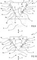
- the rotation axis Z of the wheel R and the predetermined direction X of movement of the drive unit 3 define an ideal plane P (see figures 4 , 5 , 9-11 ) of movement of the drive unit 3.
- the ideal plane P is, in a non-limiting manner, substantially vertical and is also extended along a direction of connection of the front portion 2a with the rear portion 2b of the base 2. Nevertheless, it might be possible to provide for a tire changer apparatus 1 in which the ideal plane P is substantially horizontal or tilted by an angle comprised between 0° and 90° with respect to a horizontal reference plane. With regard instead to the pre-established direction X of movement of the drive unit 3, this is extended, in a non-limiting manner, along a horizontal direction.
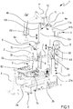
- the tire changer apparatus 1 also comprises a frame 4, it too emerging from the base 2 substantially at the rear portion 2b ( figure 1 ).
- the frame 4 is fixed to the base 2 in a distal position with respect to the drive unit 3 which is movable along the predetermined direction X close to and away from the frame 4.
- the frame 4 is mainly extended along a direction substantially parallel to the rotation axis Z of the wheel R.
- a frame 4 was illustrated that was extended, in a non-limiting manner, along a vertical direction.
- the frame 4 supports at least one first and a second device 5, 6 (see for example figures 1 , 2 , 4 , 5 and 8 ) which, as better described hereinbelow, are configured to operate on a rim and/or on a tire in order to allow the assembly and/or the disassembly of the latter on/from said rim.
- the frame 4 comprises at least one first and one second guide 11, 12 ( figure 1 ) adapted to stably support the first and second devices 5, 6; the guides 11 and 12 are placed opposite each other with respect to the ideal plane P: the first and second guides 11, 12 are both spaced from the ideal plane P and in particular placed mirrored with respect to each other.
- the first guide 11 is arranged at a distance from the ideal plane substantially identical to the distance present between the second guide 12 and the same ideal plane P.
- the first and second guides 11, 12 are extended one parallel to the other and in particular along directions parallel to the rotation axis Z of the wheel.
- the first guide 11 comprises a shaft 11a extended along an axis and constrained to a first hinge 4a of the frame ( figure 1 ).
- the shaft 11a of the first guide 11 is movable via rotation around its axis, due to a constraint of hinge type with the frame 4.
- the first guide 11 also comprises a track 11b stably constrained to the shaft 11a and extended parallel to the latter; the track 11b is fixed to the shaft 11a and hence it is also movable via rotation around the axis of the shaft 11a.
- the track 11b comprises a flat plate extended substantially over the entire axial extension of the shaft 11a ( figure 1 ).
- the track 11b is configured to directly carry the first device 5 and allow the latter to slide along a direction A1 ( figure 1 ) parallel to the axis of the shaft 11a and hence parallel to the rotation axis Z of the wheel R.
- the first guide 11 and the first device 5 are engaged by means of a constraint of sliding block type; the first device 5 is in fact slidably movable along the track 11b and blocked in the rotation with respect to the latter: the rotation of the shaft 11a, with respect to the first hinge 4a of the frame 4 around its axis, generates a corresponding rotation of the track 11b and hence of the first device 5.
- the first device 5 - in addition to slidably moving (via translation) along a direction A1 parallel to the rotation axis Z of the wheel - is also movable via rotation around the axis of the shaft 11a of the first guide 11.
- the second guide 12 comprises a shaft 12a extended along an axis and constrained to a second hinge 4b of the frame 4 ( figure 1 ).
- the shaft 12a of the second guide 12 is movable via rotation, due to the constraint of hinge type with the frame 4, around its axis.
- the second guide 12 also comprises a track 12b stably constrained to the shaft 12a and extended parallel to the latter; the track 12b is fixed to the shaft 12a and hence it is also movable via rotation around the axis of the shaft 12b.
- the track 12b comprises a flat plate extended substantially over the entire axial extension of the shaft 12a of the second guide 12 ( figure 1 ).
- the track 12b of the second guide 12 is configured to directly constrain the second device 6 and allow the latter to slide along a direction A2 ( figure 1 ) parallel to the axis of the shaft 12a of the second guide 12 and hence parallel to the rotation axis Z of the wheel.
- the second guide 12 and the second device 6 are engaged by means of a constraint of sliding block type; the second device 6 is in fact slidably movable along the track 12b of the second guide 12 and blocked in rotation with respect to the latter: the rotation of the shaft 12a, with respect to the second hinge 4b of the frame 4 around its axis, generates a corresponding rotation of the track 12b of the second guide and hence of the second device 6.
- the second device 6 - in addition to being slidably movable (via translation) along a direction parallel to the rotation axis Z of the wheel - is also movable via rotation around the axis of the shaft 12a of the second guide 12.
- a first and a second guide 11, 12 placed symmetrically with respect to the ideal plane P and having structures with substantially identical shape and size.
- the axial movement of the first and of the second device 5, 6 is generated by at least one lifting actuator 21 ( figures 1 and 2 ): such actuator 21 is configured to allow the movement of at least one of said first and second devices 5, 6 with respect to the base 2 along a direction substantially parallel to the rotation axis Z of the wheel R.
- the at least one lifting actuator 21 comprises a first and a second lifting actuator 21a, 21b (see figures 1 and 2 ) that are distinct from each other and respectively active, in an independent manner, on the first and on the second device 5, 6.
- the first lifting actuator 21a is configured to move the first device 5 along the first guide 11 of the frame 4 close to and away from the base 2 while the second lifting actuator 21b is configured to move the second device 6 along the second guide 12 of the frame 4 close to and away from the base 2.
- the tire changer apparatus 1 can comprise a control unit 50 (which in the enclosed figures has been schematized in a non-limiting manner as a control panel placed on the side of the base 2 and of the frame 4) that is connected and active in commanding the first and the second lifting actuator 21a, 21b; in particular, the control unit 50 is configured to command, in an independent manner, the lifting actuators 21a, 21b, so that the first and second devices 5, 6 can slide along the guides 11, 12 in an independent manner.
- a control unit 50 which in the enclosed figures has been schematized in a non-limiting manner as a control panel placed on the side of the base 2 and of the frame 4) that is connected and active in commanding the first and the second lifting actuator 21a, 21b; in particular, the control unit 50 is configured to command, in an independent manner, the lifting actuators 21a, 21b, so that the first and second devices 5, 6 can slide along the guides 11, 12 in an independent manner.
- the control unit 50 can command the first lifting actuator 21a to move the first device 5 along the first guide 11 such that said first device 5 can contact the tire and simultaneously command the second lifting actuator 21b to maintain the second device 6 in a raised position in which the latter is spaced from the tire; afterwards, the control unit 50 can for example command, to the first lifting actuator 21a, to move the first device 5 along the first guide 11 away from the tire and simultaneously command the second lifting actuator 21b to move the second device 6 close to the tire such that said device 6 can come into contact with the tire itself.
- the control unit 50 is also connected to the translation actuator 31, which is independent of the first and second lifting actuators 21a, 21b and active in commanding the drive unit 3; the control unit 50 is configured to command the translation actuator 31 to move the drive unit 3 along the pre-established direction X and to independently command a respective movement to at least one between said first and second lifting actuators 21a, 21b.
- the control unit 50 is nevertheless capable of monitoring and controlling the position of the drive unit 3 and hence command, in an independent manner and as a function of the processing to be executed on the wheel R, the movement of at least one between said first and second lifting actuators 21a, 21b.
- the first device 5 comprises an arm 7 hinged to the frame 4 and configured to rotate around an axis Y substantially parallel to the rotation axis Z of the wheel R.
- the arm 7 is extended between a first and a second end portion 7a, 7b (see for example figures 1 , 4 and 5 ); at the first end portion 7a, the arm 7 defines the engagement portion 5a of the first device 5 with the first guide 11.
- the engagement portion 5a defined by said first end portion of the arm 7 comprises a support, having substantially C-shaped section, engaged with the track 11b of the first guide 11.
- the support allows the arm 7 to slide along the track and to rotate together with the latter around the axis of the shaft 11a, coinciding therefore with the rotation axis Y of the first device 5.
- the rotation axis Y of the arm 7 of the first device 5 is arranged at a pre-established distance D1 ( figures 9 and 10 ) from the ideal plane P greater than 100 mm, optionally comprised between 150 and 250 mm. Such distance coincides with the distance present between the axis of the shaft 11a of the first guide 11 and the ideal plane P.
- the arm 7 of the first device 5 can be extended, in a non-limiting manner, along a main extension direction that is substantially rectilinear; nevertheless, it may be possible to make arms 7 of different shape and size.
- the arm 7 is also possible to define a tilt angle of said main extension direction with the ideal plane P to essentially define the tilt of the arm 7 with respect to said plane P.
- the first device 5 is in particular configured to rotate the arm 7 around its axis Y such that the arm 7 can define, with the ideal plane P, an angle ⁇ comprised between 10° and 45°, optionally between 15° and 30°.
- the first device 5 at least during a work condition in which said first device 5 is adapted to contact the tire, is configured to allow the rotation of the respective arm 7 so that the main extension direction of the latter substantially intersects the rotation axis Z of the wheel R (see for example figures 9 and 10 ).
- the first device 5 also comprises a tool 8 terminally carried by the arm 7 and configured to operate on a rim and/or a tire of a wheel R carried by the drive unit 3.
- the tool 8 of the first device 5 is arranged at the second end portion 7b of the arm 7 of the first device 5, hence opposite the engagement portion 5a.
- the tool 8 of the first device 5 is therefore also movable via rotation around the axis Y since it is stably carried by the arm 7 hinged to the frame 4. Even if movable via rotation around the axis Y, the tool 8 of the first device 5 is configured to be arranged at a distance D3 ( figures 9 and 10 ) from the ideal plane P greater than 40 mm, optionally comprised between 50 and 150 mm.
- the tool 8 of the first device 5 is configured to always maintain a distance D3 from said ideal plane P and thus remain, with respect to said plane P, always on the same side on which said first guide 11 is present; in the same manner, the arm 7 of the first device 5 is configured to not intersect the ideal plane P.
- the tool 8 of the first device 5 is arranged at a substantially fixed distance from the rotation axis Y of the arm 7 of the same first device 5; in other words, the distance between the first and the second end portion 7a, 7b of the arm 7 of the first device 5 is substantially fixed to thus define an arm 7 with fixed length.
- the tire changer apparatus 1 is configured to control the position of the drive unit 3, the angular position of the first device 5 with respect to the ideal plane P and the position of said first device 5 along the first guide 11.
- the angular position of the first device 5 can be defined, in case of arm 7 with rectilinear shape, such as the tilt between said arm and the ideal plane P; such tilt can also be defined (for example in the event that there is an arm 7 with curved shape or, more generally, non-rectilinear shape) such as the tilt between the ideal plane P and a virtual plane of the defined first device of the rotation axis Y of the arm 7 of the first device 5 and a geometric center of the tool 8 of the same first device 5: the first device 5 is configured to rotate with respect to the frame 4 in a manner such to maintain such tilt comprised between 10° and 45°, optionally comprised between 15° and 30°.
- the second device 6 comprises a respective arm 70 hinged to the frame 4 and terminally carrying a respective tool 80.
- the arm 70 of the second device 6 is also configured to rotate around a respective axis Y' substantially parallel to the rotation axis Z of the wheel R.
- the arm 70 of the second device 6 is extended between a first and a second end portion 70a, 70b; at the first end portion 70a, the arm 70 defines the portion 6a of engagement of the second device 6 with the second guide 12 ( figures 1 , 4 and 5 ).
- the engagement portion 6a defined by said first end portion of the arm 70 comprises a support, having substantially C-shaped section, engaged with the track 12b of the second guide 12.
- the support allows the arm 70 to slide along the track and to rotate together with the latter around the axis of the shaft 12a, coinciding therefore with the rotation axis Y' of the second device 6.
- the rotation axis Y' of the arm 70 of the second device 6 is arranged at a pre-established distance D2 ( figures 9 and 10 ) from the ideal plane P greater than 100 mm, optionally comprised between 150 and 250 mm. Such distance coincides with the distance present between the axis of the shaft 12a of the second guide 12 and the ideal plane P.
- the distance D1 present between the rotation axis Y of the arm of the first device 5 and the ideal plane P is substantially identical to the distance D2 present between the rotation axis Y' of the arm of the second device 6 and the ideal plane P.
- the first and second devices 5, 6 are configured to arrange the respective tools 8, 80 on opposite sides with respect to said ideal plane P. More in detail, the first and second devices 5, 6 are configured to arrange the rotation axes Y, Y' of the respective arms 7, 70 on opposite sides with respect to the ideal plane P as illustrated for example in figures 9 and 10 .
- the arm 70 of the second device 6 can be extended, in a non-limiting manner, along a main extension direction that is substantially rectilinear; it may however be possible to make arms of different shape and size.
- a tilt angle of said main extension direction with the ideal plane P it is also possible to define a tilt angle of said main extension direction with the ideal plane P to essentially define the tilt of the arm 70 with respect to said plane P.
- the second device 6 is in particular configured to rotate its arm 70 around its axis Y' such that the arm 70 can define, with the ideal plane P, an angle ⁇ ( figures 9 and 10 ) comprised between 10° and 45°, optionally between 15° and 30°.
- the second device 6, at least during a work condition in which said second device 6 is adapted to contact the tire, is configured to allow the rotation of the respective arm 70 so that the main extension direction of the latter substantially intersects the rotation axis Z of the wheel R (see for example figures 9 and 10 ).
- the second device 6 also comprises a respective tool 80 terminally carried by the arm 70 and configured to operate on a rim and/or a tire of a wheel R carried by the drive unit 3.
- said tool 80 is arranged at the second end portion 70b of the arm 70 of the second device 6, hence opposite the engagement portion 6a.
- the tool 80 of the second device 6 is therefore also movable via rotation around the axis Y' since it is integrally carried by the arm 70 of the same second device 6 hinged to the frame 4.
- the tool 80 carried by the arm 70 of the second device 6 is configured to be arranged at a distance D4 ( figures 9 and 10 ) from the ideal plane P greater than 40 mm, optionally comprised between 50 and 150 mm.
- the tool 80 of the second device 6 is configured to always maintain a distance D4 from said ideal plane P and hence remain, with respect to said plane P, always on the same side on which said second guide 12 is present; in the same manner, the arm 70 of the second device 6 is configured to not intersect the ideal plane P.
- the tool 80 of the second device 6 is arranged at a substantially fixed distance from the rotation axis Y' of the arm 70 of the same second device 6; in other words, the distance between the first and the second end portion 70a, 70b of the arm 70 of the second device 6 is substantially fixed to thus define an arm 70 with fixed length.
- the tire changer apparatus 1 is configured to control the position of the drive unit 3, the angular position of the second device 6 with respect to the ideal plane P and the position of said second device 6 along the second guide 12.
- the angular position of the second device 6 can be defined, in the case of arm 70 with rectilinear shape, such as the tilt between said arm and the ideal plane P; such tilt can also be defined (for example in the event that there is an arm 7 with curved shape or, more generally, non-rectilinear shape) such as the tilt present between the ideal plane and a defined virtual plane of the rotation axis Y' of the arm 70 of the second device 6 and a geometric center of the tool 80 of the same second device 6: the second device 6 is configured to rotate with respect to the frame 4 in a manner such to maintain such tilt comprised between 10° and 45°, optionally comprised between 15° and 30°.
- the first and second devices 5, 6, at least during a work condition in which both the tools 8, 80 of said first and second devices 5, 6 are adapted to contact the tire can be configured to move the respective tools such that the distance present between the tool 8 of the first device 5 and the ideal plane P is substantially identical to the distance present between the tool 80 of the second device 6 and said ideal plane P.
- the first and second devices 5, 6, at least during a work condition in which both the tools 8, 80 of said first and second devices are adapted to contact the tire can be configured to move the respective tools 8, 80 such that the angles of the virtual planes, respectively of the first and of the second device 5, 6, are substantially identical in relation to the ideal plane P.
- the rotation of the first and second devices 5, 6 can be executed, in a first embodiment, electronically by means of the control unit 50 active in commanding at least one rotation actuator or executed, in a second embodiment, mechanically by means of an interconnection system.
- the tire changer apparatus 1 comprises at least one rotation actuator active on said first and second devices 5, 6 and configured to allow the rotation of the arms 7, 70 of the latter around the respective axes Y, Y'.
- the control unit 50 is connected and active in commanding said rotation actuator and configured to manage the rotation of said devices.
- the tire changer apparatus 1 comprises a translation actuator 31 active on the drive unit 3 and configured to move the latter along the pre-established direction X close to and away from the frame 4, between a plurality of work positions; the control unit 50 active in commanding said translation actuator 31 and said rotation actuator can be configured to:
- control unit 50 can be configured to command the rotation actuator in order to rotate the arms 7, 70 of the first and second devices 5, 6 and arrange the tool 8 of the first device 5 at a distance from the ideal plane P substantially identical to a distance present between the tool 80 of the second device 6 and said ideal plane P.
- the control unit 50 is configured to arrange the virtual planes of the first and of the second device at a same tilt with respect to the ideal plane P.
- control unit 50 can be configured to command the rotation actuator in order to rotate the arms 7, 70 of the first and second devices 5, 6 so as to arrange the main extension directions of said arms 7, 70 of said first and second devices 5, 6 substantially intersecting with the rotation axis Z of the wheel R as illustrated in the figures 4 , 9 and 10 .
- control unit 50 is configured to move the drive unit 3 along the pre-established direction X and consequently move the rotation axis Z of the wheel along the ideal plane P (such movement can for example be a function of the dimensions of the wheel mounted on the drive unit 3); the control unit 50 can be configured to command, as a function of said movement, the at least one rotation actuator as a function of the movement of the drive unit 3 in a manner such to rotate the first and second devices 5, 6 so that the tools 8, 80 can reach a correct position with respect to the tire in order to execute a procedure of assembly and/or disassembly of the tire on/from the rim.
- control unit 50 configured to command the rotation of the arms 7, 70 of the first and second devices 5, 6, independent of the movement of the drive unit 3; for example, the control unit 50 can be configured to receive in inlet a representative signal of a characteristic of the wheel R and as a function of this command the rotation of the arms 7, 70 of the first and second devices 5, 6.
- the characteristic of the wheel R can for example comprise at least one from among: a diameter of the rim, a width of the rim, a diameter of the tire, a width of the tire.
- Such characteristic can be acquired by the control unit, for example by means of one or more sensors connected to the control unit 50 and configured to emit said signal representative of the characteristic of the wheel.
- the control unit 50 connected to said sensors, can be configured to process said signal and estimate the characteristic of the wheel; following the executed estimation, the control unit 50 can be configured to command a pre-established rotation of the arms 7, 70 of the first and second devices 5, 6.
- the characteristic of the wheel R can be manually inserted by an assigned operator directly into the control unit.
- the at least one actuator can comprise at least one first and second rotation actuators that are distinct and independent from each other, hence capable of operating independently from each other; the control unit 50 is configured to act by commanding said first and second rotation actuator in order to allow the independent rotation of the arms 7, 70 of the first and second devices 5, 6.
- the control unit 50 can be configured to:
- control unit 50 is active on the translation actuator 31, on the first and second lifting actuators and on the first and second rotation actuators in order to synchronize (directly or indirectly) the rotation of the first and second devices 5, 6 with the movement of the drive unit 3 (whose movement can be a function of a characteristic of the wheel, e.g. the diameter of the wheel) so as to bring the tools 8, 80 of said first and second devices 5, 6 into a correct position for the execution of a procedure of assembly and/or disassembly of the tire from rim.
- the movement of the first and second devices 5, 6 along the respective guides 11, 12 is managed by the control unit 50 depending on the distance of the wheel R from the base 2 and on the dimensions thereof, such as for example the width.
- the position and the width of the wheel R can for example be manually inserted in the control unit by an operator or they can be automatically detected by one or more sensors associable with at least one from among: the first device, the second device, the base 2, the drive unit 3, the frame 4.
- control unit 50 in carrying out the control of the above-described steps, i.e. in controlling and coordinating the various above-described actuators, cooperates with sensors comprising one or more from among encoders, position sensors, end stop sensors, angular position sensors, per se known and useful for providing position information of the various movable components to the unit.
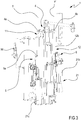
- the synchronization of the rotation of the first and second devices 5, 6 and the movement of the drive unit 3 can be managed by an interconnection system 60 of mechanical type, such as for example illustrated in figures 5-8 .
- interconnection system 60 can be configured to connect in movement the first and second devices 5, 6 with the drive unit 3; the interconnection system 60 is configured to rotate the arms 7, 70 of the first and second devices 5, 6 during the movement of the drive unit 3 along the predetermined direction X lying on the ideal plane P.
- the interconnection system 60 can comprise:
- the lever 61 and the pusher 62 are engaged in motion with each other such that, following the movement of the drive unit 3 along the predetermined direction X, the pusher 62 can rotate the at least one lever 61 and consequently the arms 7, 70 of the first and second devices 5, 6 around the respective axes Y, Y'.
- At least one between the pusher 62 and the lever 61 comprises a shaped guiding portion extended along a pre-established trajectory T; the other between said lever 61 and said pusher 62 is constrained to the shaped guiding portion and configured to be moved, during the movement of the drive unit 3 along the predetermined direction X, along the trajectory T in order to allow the rotation of the lever 61 and consequently of the arms 7, 70 of the first and second devices 5, 6, around the respective axes Y, Y'.
- Figure 6 for example illustrates a configuration of the interconnection system 60 in which the pusher 62 carried by the drive unit 3 comprises said shaped guiding portion having at least one groove 62a extended along the pre-established trajectory T; the lever 61 comprises at least one connection body 61a with stably elongated shape constrained to the first and second devices 5, 6: the lever 61 also comprises at least one projection 61b engaged via sliding within the groove 62a of the pusher 62.
- the projection 61b of the lever 61 is configured to slide within the groove 62a and guide in rotation said lever 61 with consequent rotation of the arms 7, 70 of the first and second devices 5, 6 around the respective axes Y, Y'.
- the groove 62a is illustrated which comprises, in a non-limiting manner, a first and a second groove extended along respective trajectories T lying on a plane orthogonal to the ideal plane P and orthogonal to the rotation axis Z of the wheel R; the first and second grooves are for example identical regarding shape and size and arranged symmetrically with respect to the ideal plane P.
- the lever 61 comprises a first connection body 61a stably constrained to the first device 5 by means of the track 11b of the first guide 11: the first connection body terminally carries the projection 61b comprising at least one pin engaged via sliding within the first groove.
- the lever 61 also comprises a second connection body 61a stably constrained to the second device 6 by means of the track 12b of the second guide 12: the second connection body terminally carries the projection 61b comprising at least one pin engaged via sliding within the second groove.
- the grooves 62a of the pusher 62 are moved with respect to the frame 4 and oblige the pins of the first and second levers to slide within said grooves and to follow the pre-established trajectory T suitably shaped in order to allow the simultaneous rotation of the first and second devices 5, 6 with respect to the ideal plane P.
- Figure 8 illustrates a different configuration of the interconnection system 60 in which the pusher 62 comprises a pin, while the lever 61 comprises at least one connection body 61a with stably elongated shape constrained to the first and second devices 5, 6; in such configuration, it is the connection body 61a of the lever 61 which terminally carries the shaped guiding portion extended along the pre-established trajectory T: during the movement of the drive unit 3 along the predetermined direction X and consequently of the pusher 62, the pin of the pusher 62 is configured to slide along the shaped guiding portion of the lever 61 and guide in rotation said lever 61 with consequent rotation of the arms 7, 70 of the first and second devices 5, 6 around the respective axes Y, Y'.
- the pin of the pusher 62 is defined by the casing 3c of the drive unit 3 while the shaped guiding portion of the lever 61 comprises a slot within which the casing 3c is engaged.
- the at least one lever comprises a first and a second lever; the first lever comprises a connection body 61a which is constrained to the first device 5 by means of the track of the first guide 11: said connection body 61a comprises a slot engaged with the casing 3c of the drive unit 3.
- the second lever comprises a respective connection body 61a constrained to the second device 6 by means of the plate of the second guide 12: said connection body comprises a respective slot, it too engaged with the casing 3c of the drive unit 3.
- the casing 3c is configured to slide within the slots of the first and second levers in order to guide the latter in rotation and consequently carry in rotation the arms 7, 70 of the first and second devices 5, 6 around the respective axes Y, Y'.
- the interconnection system 60 comprises at least one cam (or another mechanical device for transforming the motion) configured to transform the translational motion of the drive unit 3 into a rotational motion of the arms of the first and second devices 5, 6.
- the rotation of the arms 7, 70 can occur in a manner that is entirely independent with respect to the movement of the drive unit 3 along the direction X, in the rotation of the arms 7, 70 managed mechanically the rotation of the latter is a function of the movement X of the drive unit 3.
- FIG. 9 and 10 Schematically illustrated in figures 9 and 10 is the movement of the drive unit 3 along the direction X, which can be caused by the assembly of a different wheel R on the drive unit 3 (case shown in figures 9 and 10 in which the wheel R of figure 9 is larger than the wheel of figure 10 ); as can be seen in figures 9 and 10 , the distances D1 and D2 of the rotation axes Y, Y' of the first and second devices 5, 6 with respect to the ideal plane P remain unchanged during the rotation of the arms since they are hinged to the frame 4.
- the first and second devices 5, 6 are configured to adapt the tilt of the arms as illustrated in figures 9 and 10 in order to bring the tools 8, 80 into a position in which they execute a correct procedure of assembly and/or disassembly of a tire from a wheel.
- the tools of the first and of the second device 5, 6 can be equal to each other or have a different structure and function. Illustrated in the enclosed figures, in a non-limiting manner, is a tool of the first device 5 comprising a pressing element configured to act thrustingly on the first bead of the tire in order to allow at least one partial detachment of said first bead from the first perimeter edge of the rim.
- the pressing element comprises a rotary body configured to define, with the tire, a friction of rolling type; the rotary body is configured to rotate around an axis thereof, in an operative condition in which the wheel R rotates around the rotation axis Z and the rotary body contacts the tire.
- the rotary body comprises at least one selected from among: a disc, a cylinder, a ball.
- the tool 80 of the second device 6 can thus comprise a pressing element similar to that of the first device 5 or it can comprise, as illustrated in the enclosed figures, an inserter-extractor element configured to be radially interposed between the first perimeter edge of the rim and the first bead of the tire in order to allow the engagement-disengagement of said first bead with the first perimeter edge of the rim.
- a tire changer apparatus 1 comprising, in a non-limiting manner, a third device 90 ( figures 1A , 6-8 ) also having an arm 91 hinged to the frame 4 and configured to rotate around an axis Y substantially parallel to the rotation axis Z.
- the arm 91 of the third device 90 is extended between a first and a second end portion 91a, 91b; at the first end portion 91a, the arm 91 defines a portion 90a of engagement of the third device 90 with the first guide 11.
- the engagement portion 90a defined by said first end portion of the arm 91 comprises a support, having substantially C-shaped section, engaged with the track 11b of the first guide 11.
- the support allows the arm 7 to slide along the track and to rotate together with the latter around the axis of the shaft 11a, hence coinciding with the rotation axis Y of the first and third devices 5, 90.
- the rotation axis Y of the third device coincides with the rotation axis Y of the first device 5; both the devices 5, 90 are constrained to the track 11a of the first guide 11 by means of an identical support system having C shape. Therefore, also the rotation axis Y of the arm 91 of the third device 90 is arranged at a pre-established distance D1 ( figure 11 ) from the ideal plane P greater than 100 mm, optionally comprised between 150 and 250 mm.
- the third device 90 is thus configured to arrange the rotation axis Y of its arm 91 on an opposite side with respect to the rotation axis Y' of the arm 70 of the second device 6 with respect to said ideal plane P.
- the arm 91 of the third device 90 can be extended, in a non-limiting manner, along a main extension direction that is substantially rectilinear; nevertheless, it may be possible to make arms of different shape and size.
- the arm 91 is extended along a rectilinear direction, it is also possible to define a tilt angle ⁇ of said main extension direction with the ideal plane P to essentially define the tilt of the arm 91 with respect to said plane P.
- the third device 90 is in particular configured to rotate the arm 91 around its axis Y such that said arm 91 can define, with the ideal plane P, an angle ⁇ comprised between 10° and 45°, optionally between 15° and 30°.
- the third device 90 at least during a work condition in which said third device 91 is adapted to contact the tire, is configured to allow the rotation of the respective arm 91 so that the main extension direction of the latter substantially intersects the rotation axis Z of the wheel R (see for example figure 11 ).
- the third device 90 also comprises a respective tool 92 terminally carried by the arm 91 of the third device and configured to operate on a rim and/or a tire of a wheel R carried by the drive unit 3.
- said tool 92 is arranged at the second end portion of the arm 91 of the third device 90, hence opposite the engagement portion 90a.
- the tool 92 of the third device 90 is therefore also movable via rotation around the axis Y, since it is integrally carried by the arm 91 hinged to the frame 4. Even if movable via rotation around the axis Y, the tool 92 carried by the arm 91 of the third device 90 is configured to be arranged at a distance from the ideal plane P greater than 40 mm, optionally comprised between 50 and 150 mm.
- the tool 92 of the third device 90 is configured to always maintain a pre-established distance from said ideal plane P and thus remain, with respect to said plane P, always on the same side on which said first guide 11 is present; in the same manner, the arm 91 of the third device 90 is configured to not intersect the ideal plane P.
- the tool 92 of the third device 90 is arranged at a substantially fixed distance from the rotation axis Y of the arm 91 of the same third device 90; in other words, the distance between the first and the second end portion 91a, 91b of the arm 91 of the third device 5 is substantially fixed to thus define an arm 91 with fixed length.
- the tire changer apparatus 1 is configured to control the position of the drive unit 3, the angular position of the third device 90 with respect to the ideal plane P and the position of said third device 90 along the first guide 11.
- the angular position of the third device 90 can be defined, in the case of arm 91 with rectilinear shape, as the tilt between said arm and the ideal plane P; such tilt can also be defined (for example in the event that there is an arm 91 with curved shape or, more generally, non-rectilinear shape) as the tilt present between the ideal plane and a defined virtual plane of the rotation axis Y of the arm 91 of the third device 90 and a geometric center of the tool 92 of the same third device 90: the third device 90 is configured to rotate with respect to the frame 4 in a manner such to maintain such tilt comprised between 10° and 45°, optionally comprised between 15° and 30°.
- the first and third devices 5, 90 since they are hinged to the same first guide 11, are configured to integrally rotate with respect to the frame 4 and in particular to define, with respect to the ideal plane, substantially a same tilt. Indeed, the first and the third device 5, 90, at least during a work condition in which both the tools of said first and third devices are adapted to contact the tire, are configured to move the respective tools such that the angles of the virtual planes, respectively of the first and of the third device, are substantially identical in relation to the ideal plane P.
- the first and the third device 5, 90 at least during a work condition in which both the tools of said first and third devices are adapted to contact the tire, are configured to move the respective tools such that the distance present between the tool 8 of the first device 5 and the ideal plane P is substantially identical to the distance present between the tool 92 of the third device 90 and said ideal plane P.
- the first and third devices 5, 90 are separated from each other and independent in the translational movement along said first guide 11.
- the third device 90 is spaced from the first device 5 along said first guide 11: the first device 5 is placed at a distance from the base 2 greater than a distance between said base and the third device 90.
- the axial movement of the third device 90 is generated by at least one third lifting actuator 21c that is distinct and independent of the first and second lifting actuators 21a, 21b. in particular, the third lifting actuator 21c is configured to move the third device 90 along the first guide 11 of the frame 4 close to and away from the base 2.
- the control unit 50 is connected to and active in commanding the third lifting actuator 21c and configured to command, in an independent manner, said lifting actuators 21a, 21b, 21c such that the first, second and third devices 5, 6, 90 can slide along the guides in an independent manner.
- the tool 92 of the third device 90 can comprise a pressing element similar to that of the first device 5 or it can comprise an inserter-extractor element similar to that of the second device 6.
- a tool 92 of the third device 90 comprising a pressing element, similar to the pressing element of the first device 5, configured to act thrustingly on the second bead of the tire in order to allow at least one partial detachment of said second bead from the second perimeter edge of the rim.
- the pressing element of the third device 90 can nevertheless also be employed in order to be radially interposed between a perimeter edge of the rim and a bead of the tire.
- Also forming the object of the present invention is a process of disassembly of a tire from a rim by means of the tire changer apparatus in accordance with the above-reported description and/or in accordance with the enclosed claims.
- the disassembly process initially provides for a step of positioning the wheel on the drive unit 3. Then, the process provides for the movement of the drive unit 3 along the predetermined direction X lying on the ideal plane P; the movement of the drive unit is a function of a characteristic of the wheel, for example the diameter of the rim and/or the external diameter of the tire.
- the process also provides for a step of detecting the position of the wheel with respect to the base 2 and/or with respect to the frame; in particular, the process provides for a step of determining the width of the rim and the position of the first and second perimeter edges of the rim. In this manner, it is possible to estimate the position of the first and second beads of the tire on which the tools of the tire changer apparatus 1 must act.
- the determination of the width and of the position of the first and second perimeter edges of the rim can be automatically executed by means of the aid of one or more sensors connected to the control unit 50 and/or can be carried out by means of use of data inserted manually by an assigned operator.
- the process Before or after the movement of the drive unit, the process provides for deflating the tire, such that the same can be detached from the rim and subsequently removed.
- the process provides for the rotation of the arms of the first and second devices 5, 6 - and if present of the third device - such that the respective tools can operate on the rim and/or tire of the wheel R carried by the drive unit 3.
- the step of rotation of the arms of the first and second devices 5, 6 - and if present of the third device 90 - is carried out simultaneously with or after the movement of the drive unit 3 along the predetermined direction X, such that the main extension direction of the arms, at least during the rotation of the wheel around the rotation axis Z, substantially intersects said rotation axis Z.
- the wheel R is rotated around its axis Z; then, the tool 8 of the first device 5 is pressed on the first bead of the tire, such that the tool 8 can generate a detachment of the first bead from the first perimeter edge of the rim.
- the process also provides for, preferably simultaneously with the step of pressing the first bead, a step of pressing the second bead by means of the tool 92 of the third device 90, in a manner such to generate a detachment of the second bead from the second perimeter edge of the rim.
- the process provides for interrupting the rotation of the wheel by means of the locking of the drive unit 3 and the subsequent radial interposition of the tool 80 of the second device 6 between said first bead and the first perimeter edge of the rim; the radial interposition of the tool 80 of the second device 6, between said first bead and the edge of the rim, provides for the movement of the second device 6 along said second guide 12 close to the wheel R.
- the process can provide for the movement of the wheel, by means of the drive unit 3, along said pre-established direction X lying on the ideal plane P, in order to allow said tool 80 of the second device 6 to extract at least part of the first bead from the first perimeter edge of the rim.
- the extraction of the bead can be executed due to the use of a shaped tool 80 which allows extracting the bead by means of only the movement, away from the wheel, of the tool 80 and simultaneously maintain the position of the drive unit 3 fixed with respect to the frame 4.
- the process provides for the rotation of the wheel R around the axis Z so as to completely disengage the first bead from the first perimeter edge of the rim.
- the first device 5 is moved away from the wheel by means of the movement of the same along the first guide 11 of the frame 4, optionally away from the base 2.
- the process comprises the following steps:
- Also forming the object of the present invention is a process of assembly of a tire on a rim by means of the tire changer apparatus 1 in accordance with the above-reported description and/or in accordance with the enclosed claims.
- the assembly process initially provides for a step of assembly of the rim of the wheel R on the drive unit 3. Then, the process possibly provides for the movement of the drive unit 3 along the predetermined direction X lying on the ideal plane P; the movement of the drive unit 3 is a function of a characteristic of the wheel, for example of the diameter of the rim and/or of the external diameter of the tire to be assembled on the rim.
- the process possibly provides for the rotation of the arms 7, 70 of the first and second devices 5, 6 - and if present of the third device 90 - such that the respective tools can operate on the rim and/or tire of the wheel R carried by the drive unit 3.
- the step of rotation of the arms 7, 70 of the first and second devices 5, 6 - and if present of the third device 90 - is carried out simultaneously with or after the movement of the drive unit 3 along the predetermined direction X, such that the main extension direction of the arms, at least during the rotation of the wheel around the rotation axis Z, substantially intersects said rotation axis Z.
- the process provides for positioning the tire on the rim mounted on the drive unit 3; the tire is in particular abutted against the rim such that the second bead of the tire is abutted against the first perimeter edge of the rim. Then, the process provides for the radial interposition of the tool of the first or third device between the second bead of the tire and the first perimeter edge of the rim.
- a movement can be executed, in a non-limiting manner, of the drive unit 3 along the predetermined direction X lying on the ideal plane P so that said tool can allow the engagement of a part of the second bead with the first perimeter edge of the rim.
- the engagement of the bead can be carried out due to the use of a shaped tool which allows inserting at least part of the first bead by means of the movement, close to the wheel, of the tool and simultaneously maintaining the position of the drive unit 3 fixed with respect to the frame 4.
- the process provides for the rotation of the wheel R around the axis Z so as to completely engage the second bead with the first perimeter edge of the rim: following the complete engagement of the second bead with the first perimeter edge of the rim, the second bead results interposed between the first and second perimeter edges of the rim.
- the process provides for executing a pressing on the first bead of the tire, by means of the tool 8, 80 of the first and/or second device 5, 6: in such step, said tools are made to slide along the respective guide, moving close towards the second bead of the tire up to the partial engagement of the first bead with the first perimeter edge of the rim.
- the process provides for rotating the wheel R around the axis Z so as to completely engage the first bead to the first perimeter edge of the rim: following the complete engagement of the first bead with the first perimeter edge of the rim, the first and second beads both result interposed between the first and second perimeter edges of the rim.
Landscapes
- Engineering & Computer Science (AREA)
- Mechanical Engineering (AREA)
- Automobile Manufacture Line, Endless Track Vehicle, Trailer (AREA)
- Automatic Assembly (AREA)
- Processing And Handling Of Plastics And Other Materials For Molding In General (AREA)
- Crushing And Pulverization Processes (AREA)
- Moulds For Moulding Plastics Or The Like (AREA)
Abstract
Description
- The object of the present invention is a tire changer apparatus, a process for the disassembly from vehicle wheels and a process for the assembly of tires on vehicle wheels. The present invention can be applied in the field of construction of equipment for the assistance and repair of transport means. The present invention can also be applied in the automobile field for replacing car tires or for the first assembly of a tire on a rim of a car. The present invention can nevertheless be generally employed in all fields that require the assembly and/or the disassembly of tires from rims for many different types of vehicles, including trucks, vans, farming vehicles or motorcycles.
- As is known, tire changer apparatuses are employed today which allow executing the first assembly or the replacement of tires from rims of vehicles. Tire changer apparatuses comprise a base carrying a drive unit configured to support the wheel and to allow the rotation around an axis; such known apparatuses have a frame emerging from the base and carrying an upper pressing tool and a lower pressing tool, both configured for pressing the bead of the tire so as to allow, in step of disassembly, the unsticking of the bead from the rim and, in step of assembly, the insertion of the bead between the edges of the rim. Among the tools used by the known tire changer apparatuses, an inserter-extractor tool is also known, it too carried by the frame, configured to be radially interposed between the bead of the tire and the edge of the rim in order to allow the lifting of the bead and the partial engagement or disengagement of the latter with the edge of the rim. Due to the interaction of the tools with the tire and the simultaneous rotation of the wheel on the drive unit, the tire changer apparatuses allow inserting the tire on the rim of a wheel.
- A first type of known tire changer apparatus provides for a drive unit that is fixed with respect to the frame, configured to allow only the rotation of the wheel around its axis; such apparatus, in order to allow the assembly/disassembly of tires from rims of different dimensions, provides for the use of tools carried by extensible arms configured to move the tools apart/close together depending on the size of the rim, such that the tools themselves can operate at the bead of the tire: such tools are movable only along the extension of the arm which nevertheless maintains a fixed tilt with respect to the frame and to the base of the apparatus.
- Even if such first type of tire changer apparatus is still in use today, it is indicated that the latter has various drawbacks. A first drawback is tied to the extensibility of the arms carrying the tools, which renders the structure extremely complex and often delicate. It is in fact useful to specify that, both during the step of assembly and that of disassembly of the tire, the tools are subjected to high stresses generated by the necessary pressures to be applied on the tire. The extensible structure of the arms has section with low structural strength, which are often subjected to damage and which can consequently involve costly operations of maintenance/repair of the apparatus. It is also detected that the presence of arms with tilt fixed with respect to the frame and to the base prevents the tools from working correctly with the variation of the size of the wheel. Indeed, the correct use of the tools provides for a suitable tilt of the latter with respect to the tire and a suitable and not excessive relative distance between said tools: the impossibility of varying the tilt of the tools therefore renders the known apparatuses, just described above, not very flexible in use.
- Further tire changer apparatuses having extensible arms are described in the patent applications No.
WO2014/129476A1 and No.EP1040941A2 . Unlike the above-described tire changer apparatus, the apparatus of the patent applications No.WO2014/129476A1 and No.EP1040941A2 have a drive unit that is movable relative to the frame. The tire changer apparatus of application No.WO2014/129476A1 comprises a synchronization plate which connects the rotation of the extensible arm carrying the tool of assembly/disassembly with the axial movement of the drive unit. Otherwise, the tire changer apparatus of the patent application No.EP1040941A2 comprises an actuator for each of the movements of the tool-carrier arms and of the drive unit. - The apparatuses described in the abovementioned patent applications have the above-illustrated drawbacks linked to the structure of the extensible arms; furthermore, they have a structure that is highly complex which negatively impacts the costs of the apparatuses themselves and on the requested maintenance activities.
- A second type of tire changer apparatus, described in the European patent No.
EP1916125B1 , provides for a drive unit movable along a pre-established direction, close to and away from the frame; this tire changer apparatus only comprises two pressing tools with respect to an ideal plane defined by a rotation axis of the wheel and by the pre-established direction of movement of the drive unit. Both the pressing tools are carried by arms fixed to the frame and having a fixed length: the pressing or pressing tools are only movable close to or away from the wheel along a direction parallel to the rotation axis of the wheel. The arms with fixed length, locked to the frame, have a high structural strength and provide the correct support for the pressing tools; the apparatus described in the patent No.EP1916125B1 , unlike the apparatus of the above-described first type, is therefore strong and reliable. Nevertheless, the Applicant has detected that also the latter apparatus does not lack limitations and drawbacks. In particular, even if the drive unit allows moving the wheel close to and away from the tools, the structure of the arms prevents the tools from maintaining, upon varying the dimensions of the wheel, a correct tilt with respect to the tire and a correct distance between the same tools; this limitation prevents the apparatus from working in a correct manner with a wide range of tires with different diameter and width, a condition which renders such apparatus poorly flexible in use. - A third known type of tire changer apparatus, described in the patent No.
EP1157860B2 , provides for a unit for driving the wheel in rotation, which is movable along a pre-established direction close to and away from the frame. Such tire changer apparatus comprises an inserter-extractor tool carried by a non-extensible arm fixed to the frame, lying on an ideal plane defined by the rotation axis of the wheel and by the abovementioned direction of movement of the drive unit: the inserter-extractor tool results movable close to and away from the wheel only along a vertical direction parallel to the rotation axis of the wheel. Such tire changer apparatus also comprises an upper pressing tool and a lower pressing tool carried by arms of fixed length hinged to the frame: the upper and lower pressing tools are movable via rotation around an axis parallel to and spaced from the ideal plane. Also the apparatus described in the European patent No.EP1157860B2 has tool-carrier arms with fixed length (not extensible), therefore capable of high structural strength and capable of providing the correct support to the tools. In addition, due to the presence of the movable drive unit, together with the presence of pressing tools that can be rotated with respect to the frame, the apparatus described in the European patent No.EP1157860B2 allows at least a limited capacity to adapt the position of the tools with respect to the tire, during the operations of assembly and disassembly, with respect to the apparatuses of the first and second type that are described above. The Applicant has therefore detected that also the tire changer pursuant to the European patent No.EP1157860B2 is susceptible of improvements. In particular, even if the drive unit allows moving the wheel close to or away from the tools, the structure of the arms prevents the tools from maintaining - upon varying the dimensions of the wheel - both a correct position with respect to the tire and a correct distance between the same tools; this limitation prevents the tools from operating in an optimal manner in the steps of assembly and disassembly when a wide range of tires with different diameter must be treated. Clearly, this limitation negatively affects the effectiveness and flexibility of use of the just-described apparatus. - Object of the present invention is therefore that of solving at least one of the drawbacks and/or limitations of the preceding solutions.
- A first objective of the present invention is to provide a tire changer apparatus that is structurally robust, capable of effectively carrying out the operations of assembly and disassembly of a tire from a rim of a wheel. Another object of the present invention is that of providing a tire changer apparatus that is extremely flexible in use, in particular capable of ensuring the effective and quick assembly-disassembly of a wide array of tires with different diameter and width. Another object of the present invention is that of providing a tire changer apparatus capable of operating safely and in particular reaching the objective of assembly-disassembly of a tire from a rim without damaging the latter nor the tools of the apparatus itself. Another object of the present invention is that of providing a tire changer apparatus having a simple and compact structure, which therefore has limited production costs and which at the same time allows reducing maintenance interventions to a minimum.
- These and still other objects, which will be clearer from the following description, are substantially reached by a tire changer apparatus and by an assembly and disassembly process in accordance with one or more of the enclosed claims and/or of the following aspects.
- In one aspect, a tire changer apparatus (1) is provided for the assembly and/or disassembly of tires (P) from a rim of a wheel (R) of a vehicle, said tire changer apparatus (1) comprising:
- a base (2),
- a drive unit (3) coupled to the base (2) and configured to receive and rotate around a rotation axis (Z) at least one wheel (R) of a vehicle;
- a frame (4) emerging from the base (2), wherein the drive unit (3) is movable with respect to the base (2), along a predetermined direction (X) transverse, optionally orthogonal, to the rotation axis (Z), close to and away from the frame (4),
- at least one first and a second device (5, 6) each of which comprises:
- ∘ at least one arm (7, 70) hinged to the frame (4) and configured to rotate around a respective axis (Y, Y') substantially parallel to the rotation axis (Z) of the wheel (R),
- ∘ at least one tool (8, 80) terminally carried by the arm (7, 70) and configured to operate on a rim and/or a tire of a wheel (R) carried by the drive unit (3).
- In one aspect according to the preceding aspect the rotation axis (Z) of the wheel (R) and the predetermined direction (X) define an ideal plane (P) of movement of the drive unit (3). In one aspect according to the preceding aspect the first and second devices (5, 6) are configured to arrange the respective tools (8, 80) on opposite sides with respect to said ideal plane (P).
- In one aspect according to any one of the preceding aspects the first and second devices (5, 6) are configured to arrange the rotation axes (Y, Y') of the respective arms (7, 70) on opposite sides with respect to said ideal plane (P).
- In one aspect according to any one of the preceding aspects the rotation axis (Y) of the arm (7) of the first device (5) is arranged at a pre-established distance (D1) from the ideal plane (P) greater than 100 mm, optionally comprised between 150 and 250 mm. In one aspect according to any one of the preceding aspects the rotation axis (Y') of the arm (70) of the second device (6) is arranged at a pre-established distance (D2) from the ideal plane (P) greater than 100 mm, optionally comprised between 150 and 250 mm. In one aspect according to any one of the preceding aspects the distance between the rotation axis (Y) of the arm (70) of the first device (5) and the ideal plane (P) is substantially identical to the distance present between the rotation axis (Y') of the arm (70) of the second device (6) and the ideal plane (P).
- In one aspect according to any one of the preceding aspects the tool (8) of the first device (5) is configured to be arranged at a distance (D3) from the ideal plane (P) greater than 40 mm, optionally comprised between 50 and 150 mm. In one aspect according to any one of the preceding aspects the tool (80) of the second device (6) is configured to be arranged at a distance (D4) from the ideal plane (P) greater than 40 mm, optionally comprised between 50 and 150 mm.
- In one aspect according to any one of the preceding aspects the first and second devices (5, 6), at least during a work condition in which both the tools (8, 80) of said first and second devices (5, 6) are adapted to contact the tire, are configured to move the respective tools such that the distance present between the tool (8) of the first device (5) and the ideal plane (P) is substantially identical to the distance present between the tool (80) of the second device (6) and said ideal plane (P).
- In one aspect according to any one of the preceding aspects the tool (8) of the first device (5) is arranged at a substantially fixed distance from the rotation axis (Y) of the arm (7) of the same first device (5). In one aspect according to any one of the preceding aspects the tool (80) of the second device (6) is arranged at a substantially fixed distance of the rotation axis (Y') of the arm (70) of the same second device (6).
- In one aspect according to any one of the preceding aspects the rotation axis (Y) of the arm (7) of the first device (5) and a geometric center of the tool (8) of the same first device (5) define a virtual plane that is tilted with respect to the ideal plane (P) by an angle comprised between 10° and 45°, in particular comprised between 15° and 30°. In one aspect according to any one of the preceding aspects the rotation axis (Y') of the arm (70) of the second device (6) and a geometric center of the tool (80) of the same second device (6) define a virtual plane that is tilted with respect to the ideal plane (P) by an angle comprised between 10° and 45°, in particular comprised between 15° and 30°.
- In one aspect according to any one of the preceding aspects the first and second devices (5, 6) - at least during a work condition in which both the tools (8, 80) of said first and second devices (5, 6) are adapted to contact the tire - are configured to move the respective tools (8, 80) such that the angles of the virtual planes, respectively of the first and of the second device (5, 6), are substantially identical in relation to the ideal plane (P).
- In one aspect according to any one of the preceding aspects the first device (5) is movable with respect to the frame (4) along a direction substantially parallel to the rotation axis (Z) of the wheel (R).
- In one aspect according to any one of the preceding aspects the frame (4) comprises at least one first guide (11) extended parallel to the rotation axis (Z) of the wheel (R). In one aspect according to any one of the preceding aspects the first device (5) comprises at least one engagement portion (5a) constrained to said first guide (11) and also configured to allow the translation of the first device (5) along said first guide (11).
- In one aspect according to any one of the preceding aspects the first guide (11) comprises:
- a shaft (11a) constrained to at least one first hinge (4a) of the frame (4) and extended along an axis coinciding with the rotation axis (Y) of the arm (7) of the first device (5),
- at least one track (11b), preferably flat, stably constrained to the shaft (11a) and extended parallel to the latter, wherein the track (11b) is configured to directly engage the engagement portion (5a) of the first device (5) and allow the latter to slide along a direction parallel to the rotation axis (Y) of the arm (7) of the first device (5), optionally parallel to the rotation axis (Z) of the wheel.
- In one aspect according to any one of the preceding aspects the second device (6) is movable with respect to the frame (4) along a direction substantially parallel to the rotation axis (Z) of the wheel (R). In one aspect according to any one of the preceding aspects the frame (4) comprises at least one second guide (12) extended parallel to the rotation axis (Z) of the wheel (R). In one aspect according to any one of the preceding aspects the second device (6) comprises at least one engagement portion (6a) constrained to said second guide (12) and configured to allow the translation of the second device (6) along said second guide (12).
- In one aspect according to any one of the preceding aspects the second guide (12) comprises:
- a shaft (12a) constrained to at least one second hinge (4b) of the frame (4) and extended along an axis coinciding with the rotation axis (Y') of the arm (70) of the second device (6),
- at least one track (12b), preferably flat, stably constrained to the shaft (12a) of the second device (6) and extended parallel to the latter, said track (12b) being configured to directly engage the engagement portion (6a) of the second device (6) and allow the latter to slide along a direction parallel to the rotation axis (Y') of the arm (70) of the second device (6), optionally parallel to the rotation axis (Z) of the wheel.
- In one aspect according to any one of the preceding aspects the first and the second guide (11, 12) of the frame (4) are symmetrically arranged with respect to the ideal plane (P).
- In one aspect according to any one of the preceding aspects the first device (5) is movable via sliding along the first guide (11) independent of the relative movement via sliding of the second device (6) along said second guide (12).
- In one aspect according to any one of the preceding aspects the tire changer apparatus (1) comprises at least one lifting actuator (21) active on at least one of said first and second devices (5, 6), said lifting actuator (21) being configured to allow the movement of at least one of said first and second devices (5, 6) with respect to the base (2) along a direction substantially parallel to the rotation axis (Z) of the wheel (R).
- In one aspect according to any one of the preceding aspects the at least one lifting actuator (21) comprises a first and a second lifting actuator (21a, 21b) which are distinct and respectively active, in an independent manner, on the first and second devices (5, 6). In one aspect according to any one of the preceding aspects the first lifting actuator (21a) is configured to move the first device (5) along the first guide (11) of the frame close to and away from the base (2). In one aspect according to any one of the preceding aspects the second lifting actuator (21b) is configured to move the second device (6) along the second guide (12) of the frame close to and away from the base (2).
- In one aspect according to any one of the preceding aspects, a preponderant part of the arm (7) of the first device (5) is extended along a main extension direction that is substantially rectilinear. In one aspect according to any one of the preceding aspects the first device (5), at least during a work condition in which the tool (8) of said first device (5) is adapted to contact the tire, is configured to allow the rotation of the respective arm (7) so that the main extension direction of the latter substantially intersects the rotation axis (Z) of the wheel (R).
- In one aspect according to any one of the preceding aspects, a preponderant part of the arm (70) of the second device (6) is extended along a main extension direction that is substantially rectilinear. In one aspect according to any one of the preceding aspects the second device (6), at least during a work condition in which the tool (80) of said second device (6) is adapted to contact the tire, is configured to allow the rotation of the respective arm (70) so that the main extension direction of the latter substantially intersects the rotation axis (Z) of the wheel (R).
- In one aspect according to any one of the preceding aspects the tire changer apparatus (1) comprises at least one translation actuator (31) active on the drive unit (3) and configured to move the latter along the pre-established direction (X) close to and away from the frame (4), between a plurality of work positions.
- In one aspect according to any one of the preceding aspects the tire changer apparatus (1) comprises at least one rotation actuator active on said first and second devices (5, 6) and configured to allow the rotation of the arms (7, 70) of the latter around the respective axes (Y, Y'), between a plurality of work positions.
- In one aspect according to any one of the preceding aspects the tire changer apparatus (1) comprises at least one control unit (50) active in commanding said translation actuator (3) configured to command the translation actuator (31), in order to move the drive unit (3) into a work position in which the tools (8, 80) of the first and second devices (5, 6) are capable of operating on the rim and/or tire of a wheel (R) mounted on the drive unit (3).
- In one aspect according to any one of the preceding aspects the tire changer apparatus (1) comprises at least one control unit (50) active in commanding said rotation actuator, in which the control unit (50) is configured to command the rotation actuator in order to rotate the arms (7, 70) of the first and second devices (5, 6) with respect to their axes (Y, Y') and arranging the latter in an operative position in which the tools (8, 80) of the first and second devices (5, 6) are capable of operating on the rim and/or tire of a wheel (R) mounted on the drive unit (3).
- In one aspect according to any one of the preceding aspects the control unit (50) is configured to command the rotation actuator to rotate the arms (7, 70) of the first and second devices (5, 6) and arranging the tool (8) of the first device (5) to a distance from the ideal plane (P) substantially identical to a distance between the tool (80) of the second device (6) and said ideal plane (P).
- In one aspect according to any one of the preceding aspects the control unit (50) is configured to command the rotation actuator to rotate the arms (7, 70) of the first and second devices (5, 6) so as to arrange the main extension directions of said arms (7, 70) of said first and second devices (5, 6) substantially intersecting the rotation axis (Z) of the wheel (R).
- In one aspect according to any one of the preceding aspects the at least one rotation actuator comprises at least one first and a second rotation actuator that are distinct and independent from each other. In one aspect according to any one of the preceding aspects the control unit (50) is configured to act by commanding said first and second rotation actuator to allow the independent rotation of the arms (7, 70) of the first and second devices (5, 6).
- In one aspect according to any one of the preceding aspects the control unit (50) is configured to:
- receiving, in inlet, at least one representative signal of a characteristic of a wheel (R),
- as a function of said representative signal, commanding the translation actuator (31) to move the drive unit (3) in a pre-established work position.
- In one aspect according to any one of the preceding aspects the control unit (50) is configured to receive, in inlet, said representative signal by means of at least one from among:
- a manual insertion by an operator of a parameter representative of said characteristic of a wheel (R),
- a measurement executed by means of one or more sensors connected to the control unit (50) and configured to emit said representative signal of a characteristic of a wheel (R).
- In one aspect according to any one of the preceding aspects the control unit (50) is configured to command, depending on the work position reached by the drive unit (3) and/or as a function of a representative signal of a characteristic of a wheel (R), the first and the second rotation actuator to rotate the arms (7, 70) of the first and second devices (5, 6) so as to arrange the respective tools (8, 80) in an operative position in which they are capable of operating on a rim and/or a tire of a wheel (R) carried by the drive unit (3).
- In one aspect according to any one of the preceding aspects the control unit (50) is configured to command, depending on the work position reached by the drive unit (3) and/or as a function of a representative signal of a characteristic of a wheel (R), the first and the second rotation actuator in an independent manner in order to rotate the arms (7, 70) of the first and second devices (5, 6) so as to arrange the respective tools (8, 80) in an operative position in which they are capable of operating on a rim and/or a tire of a wheel (R) carried by the drive unit (3).
- In one aspect according to any one of the preceding aspects the control unit (50), following the rotation of the arms (7, 70), is configured to command the lifting actuator (21) to move at least one of said first and second devices (5, 6) along a direction substantially parallel to the rotation axis (Z) of the wheel (R) in order to bring at least one of the tools (8, 80) of said first and second devices (5, 6) in contact with the rim and/or the tire of the wheel (R) carried by the drive unit (3).
- In one aspect according to any one of the preceding aspects the tire changer apparatus (1) comprises:
- at least one translation actuator (31) active on the drive unit (3) and configured to move the latter along the predetermined direction (X) close to and away from the frame (4), between a plurality of work positions,
- at least one interconnection system (60) configured to connect in movement the first and second devices (5, 6) with the drive unit (3), the interconnection system (60) being configured to rotate the arms (7, 70) of the first and of the second device (5, 6) during the movement of the drive unit (3) along the predetermined direction (X).
- In one aspect according to the preceding aspect, the predetermined direction (X) lies on the ideal plane (P). In one aspect according to any one of the preceding aspects the interconnection system (60) comprises:
- at least one lever (61) stably constrained to the first and second devices (5, 6) and configured to rotate the arms (7, 70) of the latter around their axes (Y, Y'),
- at least one pusher (62) stably carried by the drive unit (3) and movable together with the latter along the predetermined direction (X).
- In one aspect according to any one of the preceding aspects the lever and the pusher are engaged in motion with each other such that, following the movement of the drive unit (3) along the predetermined direction (X), the pusher can rotate the at least one lever and consequently the arms (7, 70) of the first and second devices (5, 6) around the respective axes (Y, Y').
- In one aspect according to any one of the preceding aspects, at least one between said pusher (62) and lever (61) comprises a shaped guiding portion extended along a pre-established trajectory (T),
wherein the other between said lever and pusher is constrained to the shaped guiding portion and configured to be moved, during the movement of the drive unit (3) along the predetermined direction (X), along said trajectory (T) in order to allow the rotation of the lever (61) and consequently of the arms (7, 70) of the first and second devices (5, 6) around the respective axes (Y, Y'). - In one aspect according to any one of the preceding aspects:
- the pusher (62) comprises said shaped guiding portion having at least one groove (62a) extended along the pre-established trajectory (T),
- the lever (61) comprises at least one connection body (61a) with elongated shape, stably constrained to the first and/or second device (5, 6), the lever also comprising at least one projection (61b) engaged via sliding within the groove (62a) of the pusher (62),
- In one aspect according to any one of the preceding aspects the at least one groove (62a) comprises a first and a second groove. In one aspect according to the preceding aspect the first and the second groove are extended along respective trajectories (T) lying on a plane. In one aspect according to the preceding aspect the lying plane of the first and second groove is orthogonal to the rotation axis (Z) of the wheel (R) and optionally orthogonal to the ideal plane (P). In one aspect according to any one of the preceding aspects the first and the second groove are arranged symmetrically with respect to each other, optionally with respect to the ideal plane (P). In one aspect according to any one of the preceding aspects the first and the second groove have identical shape and size.
- In one aspect according to any one of the preceding aspects the lever (61) comprises a first connection body stably constrained to the first device (5), the first connection body terminally carrying the projection (61b) comprising at least one pin engaged via sliding within the first groove.
- In one aspect according to any one of the preceding aspects the lever (61) comprises a second connection body stably constrained to the second device (6), the second connection body terminally carrying the projection (61b) comprising at least one pin engaged via sliding within the second groove.
- In one aspect according to any one of the preceding aspects:
- the pusher (62) comprises at least one pin,
- the lever (61) comprises at least one connection body (61a) with elongated shape, stably constrained to the first and/or second device (5, 6), the lever (61) comprising said shaped guiding portion extended along the pre-established trajectory (T) which is terminally carried by the connection body (61a).
- In one aspect according to any one of the preceding aspects, during the movement of the drive unit (3) along the predetermined direction (X) and consequently of the pusher (62), the pin of the pusher (62) is configured to slide along the shaped guiding portion of the lever (61) and guide said lever (61) in rotation, with consequent rotation of the arms (7, 70) of the first and second devices (5, 6) around the respective axes (Y, Y').
- In one aspect according to any one of the preceding aspects the drive unit (3) comprises an outer casing (3c) emerging from the base (2) parallel to the direction of rotation (Z) of the wheel (R), wherein the projection of the pusher (62) is defined by a portion of said casing (3c) of the drive unit (3), and wherein the guiding portion of the lever (61) comprises a slot within which the casing (3c) of the drive unit (3) is engaged.
- In one aspect according to any one of the preceding aspects the at least one lever comprises a first and a second lever,
- the first lever comprises a connection body (61a) constrained to the first device (5) and also comprises a slot engaged with the casing (3c) of the drive unit (3),
- the second lever comprises a respective connection body (61a) constrained to the second device (6) and also comprises a slot, it too engaged with the casing (3c) of the drive unit (3).
- In one aspect according to any one of the preceding aspects, during the movement of the drive unit (3) and consequently of the support casing (3c) along the predetermined direction (X), the casing (3c) is configured to slide within the slots of the first and second lever in order to guide the latter in rotation and consequently rotate the arms (7, 70) of the first and second devices (5, 6) around the respective axes (Y, Y').
- In one aspect according to any one of the preceding aspects the interconnection system (60) comprises at least one cam configured to transform the translational motion of the drive unit (3) into a rotational motion of the arms (7, 70) of the first and second devices (5, 6).
- In one aspect according to any one of the preceding aspects the wheel (R) mountable on the drive unit (3) is of the type comprising:
- a rim comprising a hub configured to allow the assembly of the rim on the vehicle and a first and second perimeter edge that are opposite and configured to allow the engagement of a tire,
- a tire comprising:
- ∘ a first bead configured to be engaged with the first perimeter edge of the rim,
- ∘ a second bead configured to be engaged with the second perimeter edge of the rim,
- ∘ a tread configured to define, in use conditions on a vehicle, the element of contact of the tire with the asphalt,
- ∘ a first flank which connects the first bead to the tread,
- ∘ a second flank which connects the second bead to the tread.
- In one aspect according to any one of the preceding aspects the tool (8) of the first device (5) comprises a pressing element configured to act thrustingly on the first bead of the tire in order to allow at least one partial detachment of said first bead from the first perimeter edge of the rim.
- In one aspect according to any one of the preceding aspects the tool (80) of the second device (6) comprises an inserter-extractor element configured to be radially interposed between the first perimeter edge of the rim and the first bead of the tire in order to allow the engagement-disengagement of said first bead from the first perimeter edge of the rim.
- In one aspect according to any one of the preceding aspects the pressing element comprises a rotary body configured to define a friction of rolling type with the tire, the rotary body being configured to rotate around an axis thereof in an operative condition in which the wheel (R) revolves around the rotation axis (Z) and the rotary body contacts the tire. In one aspect according to any one of the preceding aspects the rotary body comprises at least one selected from among: a disc, a cylinder, a ball.
- In one aspect according to any one of the preceding aspects the tire changer apparatus (1) comprises at least one third device (90) comprising:
- at least one arm (91) hinged to the frame (4) and configured to rotate around a respective axis (Y) substantially parallel to the rotation axis (Z) of the wheel (R),
- at least one tool (92) terminally carried by the arm (91) and configured to operate on a rim and/or a tire of a wheel (R) carried by the drive unit (3),
- In one aspect according to any one of the preceding aspects the third device (90) is configured to arrange the rotation axis (Y) of its arm (91) on an opposite side with respect to the rotation axis (Y') of the arm (70) of the second device (6) with respect to said ideal plane (P).
- In one aspect according to any one of the preceding aspects the rotation axis (Y) of the arm (91) of the third device (90) coincides with the rotation axis (Y) of the arm (7) of the first device (5).
- In one aspect according to any one of the preceding aspects the tool (92) of the third device (90) is arranged at a substantially fixed distance from the rotation axis (Y) of the respective arm (91) of the same third device (90).
- In one aspect according to any one of the preceding aspects the first and the third device (5, 90), at least during a work condition in which both the tools of said first and third devices are adapted to contact the tire, are configured to move the respective tools (8, 92) such that the distance present between the tool (8) of the first device (5) and the ideal plane (P) results substantially identical to the distance present between the tool (92) of the third device (90) and said ideal plane (P).
- In one aspect according to any one of the preceding aspects the rotation axis (Y) of the arm (91) of the third device (90) and a geometric center of the tool (92) of the same third device (90) define a virtual plane that is tilted with respect to the ideal plane (P) by an angle comprised between 10° and 45°, in particular comprised between 15° and 30°.
- In one aspect according to any one of the preceding aspects the first and the third device (5, 90), at least during a work condition in which both the tools (8, 92) of said first and third devices are adapted to contact the tire, are configured to move the respective tools such that the angles of the virtual planes, respectively of the first and of the third device, are substantially identical in relation to the ideal plane (P).
- In one aspect according to any one of the preceding aspects the third device (90) is movable with respect to the frame (4) along a direction substantially parallel to the rotation axis (Z) of the wheel (R).
- In one aspect according to any one of the preceding aspects the third device (90) comprises at least one engagement portion (90a) hinged to the first guide (11) of the frame (4) and also configured to allow the translation of the third device (90) along said first guide (11).
- In one aspect according to any one of the preceding aspects the third device (90) is movable via sliding along the first guide (11) independent of the relative movement via sliding of the first device (5) along said same first guide (11).
- In one aspect according to any one of the preceding aspects the at least one lifting actuator (21) comprises at least one third lifting actuator (21c) that is distinct and independent of the first and second lifting actuators (21a, 21b), wherein the third lifting actuator (21c) is configured to move the third device (90) along the first guide (11) of the frame (4) close to and away from the base (2).
- In one aspect according to any one of the preceding aspects at least one preponderant part of the arm (91) of the third device (90) is extended along a main extension direction that is substantially rectilinear, wherein the third device (90), at least during a work condition in which the tool (92) of said third device (90) is adapted to contact the tire, is configured to allow the rotation of the respective arm (91) so that the main extension direction of the latter substantially intersects the rotation axis (Z) of the wheel (R).
- In one aspect according to any one of the preceding aspects the third device (90) is spaced from the first device (5) along said first guide (11). In one aspect according to any one of the preceding aspects the first device (5) is placed at a distance from the base (2) greater than a distance between said base (2) and the third device (90). In one aspect according to any one of the preceding aspects the third device (90) is integral with the first device (5) in the rotation motion around the axis (Y). In one aspect according to any one of the preceding aspects the first and second devices (5, 90) are configured to integrally rotate around the same first guide (11) of the frame (4).
- In one aspect according to any one of the preceding aspects the drive unit (3) comprises:
- at least one motorized shaft (3a) emerging from the base (2) and extended between a first and a second end portion, wherein the shaft (3a) is engaged with the base (2) at the first end portion,
- at least one support plate (3b) constrained to the motorized shaft (3a) at the second end portion, on the opposite side with respect to the base (2), said connection plate (3b) being configured to stably support and engage a rim of a wheel (R).
- In a further aspect a process is provided for disassembly of a tire from a rim of a wheel of a vehicle by means of a tire changer apparatus (1) in accordance with any one of the preceding aspects.
- In one aspect according to any one of the preceding aspects the wheel (R) is of the type comprising:
- a rim comprising a hub configured to allow the assembly of the rim on the vehicle and a first and second perimeter edge that are opposite and configured to allow the engagement of a tire,
- a tire comprising:
- ∘ a first bead configured to be engaged with the first perimeter edge of the rim,
- ∘ a second bead configured to be engaged with the second perimeter edge of the rim,
- ∘ a tread configured to define, in use conditions on a vehicle, the element of contact of the tire with the asphalt,
- ∘ a first flank which connects the first bead to the tread,
- ∘ a second flank which connects the second bead to the tread,
- mounting the wheel (R) on the drive unit (3),
- moving the drive unit (3) along the predetermined direction (X),
- rotating the arms (7, 70) of the first and second devices (5, 6) such that the respective tools (8, 80) can operate on the rim and/or tire of the wheel (R) carried by the drive unit (3).
- In one aspect according to any one of the preceding aspects the step of rotating the arms is carried out as a function of a work position reached by the drive unit (3) and/or as a function of a representative signal of a characteristic of a wheel (R).
- In one aspect according to any one of the preceding aspects the representative signal of a characteristic of the wheel (R) can be obtained by means of:
- a manual insertion by an operator of a parameter representative of at least one characteristic of the wheel (R),
- a measurement executed by means of one or more sensors, optionally connected to a control unit (50), configured to emit said representative signal of a characteristic of a wheel (R).
- In one aspect according to any one of the preceding aspects the characteristic of the wheel (R) can comprise at least one from among:
- a diameter of the rim,
- a diameter of the tire,
- the width of the rim, wherein the width of the rim is defined by a distance between the first and the second perimeter edge of said rim,
- the width of the tire, wherein the width of the tire is defined by a distance between the first and the second flank of the tire.
- In one aspect according to any one of the preceding aspects, the process also comprises the steps of:
- rotating the wheel (R) around the rotation axis (Z),
- pressing the first bead of the tire by means of the tool (8) of the first device (5) so as to generate a detachment of the first bead from the first perimeter edge of the rim,
- following the detachment of the first bead from the first edge of the rim, radially interposing the tool (80) of the second device (6) between said first bead and the first perimeter edge of the rim,
- extracting at least part of the first bead from the first perimeter edge of the rim by means of said tool (80) of the second device (6),
- following the partial extraction of the first bead from the first perimeter edge of the rim and during the radial interposition of the tool (80) of the second device (6) between said first bead and the first perimeter edge of the rim, rotating the wheel (R) around the rotation axis (Z) so as to completely disengage the first bead from the first perimeter edge of the rim.
- In one aspect according to any one of the preceding aspects, following the assembly of the wheel on the drive unit (3) and before rotating the same, the process comprises the steps of:
- acquiring at least one first characteristic representative of at least one from between the diameter of the rim and the diameter of the tire of the wheel mounted on the drive unit (3),
- as a function of said first characteristic, executing the movement of the drive unit (3) along the predetermined direction (X) so as to position the wheel in a desired work position.
- In one aspect according to any one of the preceding aspects, the step of rotation of the arms (7, 70) of the first and second devices (5, 6) is carried out simultaneously with or after the movement of the drive unit (3) along the predetermined direction (X), such that the main extension direction of the arms (7, 70) of the first and second devices (5, 6), at least during the rotation of the wheel around the rotation axis (Z), substantially intersects said rotation axis (Z) of the wheel.
- In one aspect according to any one of the preceding aspects, following the radial interposition of the tool (80) of the second device (6) between said first bead and the edge of the rim, the process provides for the detachment of the first device (5) of the wheel (R).
- In one aspect according to any one of the preceding aspects, following the radial interposition of the tool (80) of the second device (6) between said first bead and the edge of the rim, the first device (5) is moved away from the wheel by means of the movement of the same along the first guide (11) of the frame (4).
- In one aspect according to any one of the preceding aspects the step of radially interposing the tool (80) of the second device (6) between said first bead and the edge of the rim provides for moving the second device (6) along said second guide (12) close to the wheel (R).
- In one aspect according to any one of the preceding aspects the step of extracting at least part of the first bead from the first perimeter edge of the rim comprises at least one of the following sub-steps:
- moving the wheel (R) by means of the drive unit (3) along the pre-established direction (X), optionally lying on the ideal plane (P), during the radial interposition of the tool (8) of the second device (6) between said first bead and the edge of the rim,
- moving the tool (80) of the second device (6) along the second guide (12) away with respect to the base (2). i.e. according to an exit direction of the tool (80) from the rim of the wheel.
- In one aspect according to any one of the preceding aspects the process also comprises the step of pressing the second bead of the tire by means of the tool (92) of the or of a third device (90) so as to generate a detachment of the second bead from the second perimeter edge of the rim.
- In one aspect according to any one of the preceding aspects, the step of detachment of the second bead is carried out before the step of radial interposition of the tool (80) of the second device (6) between said first bead and the edge of the rim.
- In one aspect according to any one of the preceding aspects, following the complete disengagement of the first bead from the first perimeter edge of the rim, the process comprises the following steps:
- stopping the rotation of the wheel (R) around its rotation axis (Z),
- at least partly placing the second bead of the tire in contact with the first perimeter edge of the rim,
- following the contact of the second bead of the tire with the first perimeter edge of the rim, radially interposing the tool (92) of the third device (90) between said second bead and the first perimeter edge of the rim in order to allow said tool (92) of the third device (90) to extract at least part of the second bead from the first perimeter edge of the rim,
- following the partial extraction of the second bead from the first perimeter edge of the rim and during the radial interposition of the tool (92) of the third device (90) between said second bead and the first perimeter edge of the rim, rotating the wheel (R) around the rotation axis (Z) so as to completely disengage the tire from the rim.
- In a further aspect, a process is provided for assembly of a tire on a rim of a wheel of a vehicle by means of a tire changer apparatus (1) in accordance with any one of the preceding aspects.
- In one aspect according to any one of the preceding aspects the wheel (R) is of the type comprising:
- a rim comprising a hub configured to allow the assembly of the rim on the vehicle and a first and second perimeter edge that are opposite and configured to allow the engagement of a tire,
- a tire comprising:
- ∘ a first bead configured to be engaged with the first perimeter edge of the rim,
- ∘ a second bead configured to be engaged with the second perimeter edge of the rim,
- ∘ a tread configured to define, in use conditions on a vehicle, the element of contact of the tire with the asphalt,
- ∘ a first flank which connects the first bead to the tread,
- ∘ a second flank which connects the second bead to the tread,
- placing the second bead of the tire in contact with the first perimeter edge of the rim,
- radially interposing the tool (8, 92) of the first or third device (5, 90) between the second bead of the tire and the first perimeter edge of the rim,
- moving the drive unit (3) along the predetermined direction (X), optionally lying on the ideal plane (P), so that said tool can allow the engagement of a part of the second bead with the first perimeter edge of the rim,
- following the partial engagement of the second bead with the first perimeter edge of the rim and during the radial interposition of the tool between said second bead and the first perimeter edge of the rim, rotating the wheel (R) around the rotation axis (Z) so as to completely engage the second bead to the first perimeter edge of the rim, wherein, following the complete engagement of the second bead with the first perimeter edge of the rim, said second bead results interposed between the first and the second perimeter edge of the rim,
- arranging the second bead at the second perimeter edge of the rim and arranging the first bead at the first perimeter edge of the rim,
- pressing, with the tool (8, 80) of the first and/or second device (5, 6), the first bead towards the second bead of the tire up to the partial engagement of the first bead with the first perimeter edge of the rim,
- following the partial engagement of the first bead to the first perimeter edge of the rim and during the action of pressing the tool of the first and/or second device on the first bead, rotating the wheel (R) around the rotation axis (Z) so as to completely engage the first bead to the first perimeter edge of the rim, wherein, following the complete engagement of the first bead to the first perimeter edge of the rim, the first and the second bead both result interposed between the first and the second perimeter edge of the rim.
- Several embodiments and several aspects of the finding will be described hereinbelow with reference to the enclosed drawings, provided only as a non-limiting example, in which:
-
Figures 1 and2 are perspective views of a tire changer apparatus in accordance with the present invention; -
Figures 1A and2B are detailed views respectively of the tire changer apparatus offigures 1 and2 ; -
Figure 3 is a further perspective view of a tire changer apparatus in accordance with the present invention; -
Figure 4 is a top view of a tire changer apparatus in accordance with the present invention. Infigure 4 , an operative condition is schematized in which a pair of tools of the tire changer apparatus is arranged at a wheel carried by a drive unit of the same tire changer apparatus; -
Figure 5 e a further top view of a tire changer apparatus in accordance with the present invention, lacking wheel; -
Figure 6 is a detailed view of the apparatus offigure 5 ; -
Figure 7 is a detailed side view of a tire changer apparatus in accordance with the present invention; -
Figure 8 is a further perspective view of a tire changer apparatus in accordance with the present invention; -
Figures 9-11 schematically show different operative conditions of a tire changer apparatus in accordance with the present invention. - It is observed that in the present detailed description, corresponding parts illustrated in the various figures are indicated with the same reference numbers. The figures could illustrate the object of the invention by means of representations that are not in scale; therefore, parts and components illustrated in the figures relative to the object of the invention might only regard schematic representations.
- The terms "horizontal" or "vertical", used in relation to components of the tire changer apparatus, refer to a use condition of the same during which the apparatus executes, or is usable for executing, a procedure of assembly and/or disassembly of a tire from a rim of a wheel.
- The tire changer apparatus described and claimed hereinbelow can comprise/use at least one control unit set for controlling operative conditions implemented by the same apparatus and/or for controlling the steps of the process of disassembly and assembly of a tire from/on a rim of a wheel. The control unit can be a single unit or be formed by a plurality of separate control units depending on the design selections and on the operative needs.
- With 'control unit' it is intended component of electronic type which can comprise at least one of the following: a digital processor (CPU), a circuit of analog type, or a combination of one or more digital processors with one or more circuits of analog type. The control unit can be "configured" or "programmed" for executing several steps: this can be attained in practice with any means that allows configuring or programming the control unit. For example, in the case of a control unit comprising one or more CPUs and one or more memories, one or more programs can be stored in suitable memory banks connected to the CPU or to the CPUs; the program or programs contain instructions which, when executed by the CPU or by the CPUs, program or configure the control unit in order to execute the operations described in relation to the control unit. Alternatively, if the control unit is or comprises circuitry of analog type, then the circuit of the control unit can be designed in order to include circuitry configured, in use, for processing electrical signals so as to execute the steps relative to the control unit.
Parts of the process described herein can be attained by means of a data processing unit, or control unit, which can be technically substituted with one or more computers conceived for executing a portion of software or firmware program loaded on a memory support. Such software program can be written in any one programming language of known type. The computers, if there are two or more of these, can be connected together by means of a data connection such that their computing powers are shared in any manner; the same computers can therefore be installed in positions that are even geographically different, attaining a distributing computing environment by means of the aforesaid data connection.
The data processing unit, or control unit, can be a processor of general purpose type, configured to execute one or more parts of the process identified in the present document through the software or firmware program, or be an ASIC or dedicated processor or a FPGA, specifically programmed for executing at least part of the operations of the process described herein.
The memory support can be non-transient and can be inside or outside the processor, or control unit, or data processing unit, and can - specifically - be a memory geographically situated remotely with respect to the electronic processor. The memory support can also be physically divided into multiple portions, or in cloud form, and the software or firmware program can physically provide for portions stored on memory portions that are geographically divided from each other. - With "actuator" it is intended any one device capable of causing a movement on a body, e.g. upon command of the control unit (reception by the actuator of a command sent by the control unit). The actuator can be of electric type (e.g. an electric motor), pneumatic type, mechanical type (e.g. with spring), oil-pressure type or of still another type.
- With 'wheel' (R) it is intended an assembly comprising a rim coupled to a tire.
- With 'rim' it is intended a component adapted to support a tire and comprising an anchorage zone where a hub is defined for the engagement with an axle of the wheel of a vehicle. The rim externally comprises a seat, extended in radially outer position and axially delimited by a first and by a second perimeter edge: at the seat, the tire is engaged. With 'tire' it is intended any one covering element, e.g. multilayer, mountable at the seat of a rim of a vehicle. The tire comprises:
- a first bead configured to be engaged with the first edge of the rim,
- a second bead configured to be engaged with the second edge of the rim,
- a tread configured to define the contact element of the tire with the ground,
- a first flank which connects the first bead to the tread,
- a second flank which connects the second bead to the tread,
-
Reference number 1 overall indicates a tire changer apparatus for the assembly and/or the disassembly of tires from a rim of a wheel R. As is visible in the enclosed figures, theapparatus 1 comprises abase 2 defining the support element of the various parts of theapparatus 1 described hereinbelow. - The
tire changer apparatus 1 also comprises adrive unit 3, coupled to thebase 2, configured to receive and engage a wheel R; thedrive unit 3 is also configured to allow the rotation of the wheel R around a rotation axis Z. Thedrive unit 3 comprises amotorized shaft 3a emerging from thebase 2 and extended between a first and a second end portion; the first end portion of themotorized shaft 3a is placed at thebase 2 while the second end portion, emerging from thebase 2, carries a plate or other support means 3b in order to stably support and engage a rim of a wheel R. In detail, thesupport plate 3b is configured to be constrained directly to the anchorage zone of the rim and rotate integrally with themotorized shaft 3a around an axis coinciding with the rotation axis Z. In the enclosed figures, the rotation axis Z of the wheel is extended, in use conditions of thetire changer apparatus 1, along a direction that is substantially vertical; nevertheless it might be possible to arrange adrive unit 3, configured to rotate the wheel around an axis Z that is substantially horizontal or around an axis that is tilted, by an angle comprised between 0° and 90°, with respect to a horizontal reference plane. Thedrive unit 3 can also comprise anexternal casing 3c in tubular form, optionally with circular section; thecasing 3c can emerge from thebase 2, parallel to the direction of rotation Z, and at least partly enclose themotorized shaft 3a so as to define a case adapted to at least partly enclose and protect themotorized shaft 3a. - As is visible for example in
figure 1 , thedrive unit 3 is arranged in interposition between afront portion 2a and arear portion 2b of thebase 2. Thedrive unit 3 is movable with respect to thebase 2 along a predetermined direction X that is transverse, optionally orthogonal, to the rotation axis Z, close to and away from therear portion 2b of thebase 2. In particular, theapparatus 1 comprises at least one translation actuator 31 (figure 7 ) - for example comprising a pneumatic or oil-pressure actuator or an actuator driven by an electric motor - configured to act thrustingly on thedrive unit 3 so as to allow the movement thereof (the translation) along the predetermined direction X. As is for example visible infigure 7 , thetranslation actuator 31 can be constrained on one side to a fixed portion of thebase 2 and on the other side to thedrive unit 3; thetranslation actuator 31 can be placed at the first end portion of themotorized shaft 3a of thedrive unit 3, as is for example illustrated infigure 7 . - The rotation axis Z of the wheel R and the predetermined direction X of movement of the
drive unit 3 define an ideal plane P (seefigures 4 ,5 ,9-11 ) of movement of thedrive unit 3. In the embodiment of thetire changer apparatus 1 illustrated in the enclosed figures, the ideal plane P is, in a non-limiting manner, substantially vertical and is also extended along a direction of connection of thefront portion 2a with therear portion 2b of thebase 2. Nevertheless, it might be possible to provide for atire changer apparatus 1 in which the ideal plane P is substantially horizontal or tilted by an angle comprised between 0° and 90° with respect to a horizontal reference plane. With regard instead to the pre-established direction X of movement of thedrive unit 3, this is extended, in a non-limiting manner, along a horizontal direction. - As is visible from the enclosed figures, the
tire changer apparatus 1 also comprises aframe 4, it too emerging from thebase 2 substantially at therear portion 2b (figure 1 ). Theframe 4 is fixed to thebase 2 in a distal position with respect to thedrive unit 3 which is movable along the predetermined direction X close to and away from theframe 4. Theframe 4 is mainly extended along a direction substantially parallel to the rotation axis Z of the wheel R. In the enclosed figures, aframe 4 was illustrated that was extended, in a non-limiting manner, along a vertical direction. - The
frame 4 supports at least one first and asecond device 5, 6 (see for examplefigures 1 ,2 ,4 ,5 and8 ) which, as better described hereinbelow, are configured to operate on a rim and/or on a tire in order to allow the assembly and/or the disassembly of the latter on/from said rim. - In detail, the
frame 4 comprises at least one first and onesecond guide 11, 12 (figure 1 ) adapted to stably support the first andsecond devices guides second guides first guide 11 is arranged at a distance from the ideal plane substantially identical to the distance present between thesecond guide 12 and the same ideal plane P. The first andsecond guides - In detail, the
first guide 11 comprises ashaft 11a extended along an axis and constrained to afirst hinge 4a of the frame (figure 1 ). Theshaft 11a of thefirst guide 11 is movable via rotation around its axis, due to a constraint of hinge type with theframe 4. Thefirst guide 11 also comprises atrack 11b stably constrained to theshaft 11a and extended parallel to the latter; thetrack 11b is fixed to theshaft 11a and hence it is also movable via rotation around the axis of theshaft 11a. Thetrack 11b comprises a flat plate extended substantially over the entire axial extension of theshaft 11a (figure 1 ). As better described hereinbelow, thetrack 11b is configured to directly carry thefirst device 5 and allow the latter to slide along a direction A1 (figure 1 ) parallel to the axis of theshaft 11a and hence parallel to the rotation axis Z of the wheel R. In more detail, thefirst guide 11 and thefirst device 5 are engaged by means of a constraint of sliding block type; thefirst device 5 is in fact slidably movable along thetrack 11b and blocked in the rotation with respect to the latter: the rotation of theshaft 11a, with respect to thefirst hinge 4a of theframe 4 around its axis, generates a corresponding rotation of thetrack 11b and hence of thefirst device 5. Indeed, the first device 5 - in addition to slidably moving (via translation) along a direction A1 parallel to the rotation axis Z of the wheel - is also movable via rotation around the axis of theshaft 11a of thefirst guide 11. - In the same manner, the
second guide 12 comprises ashaft 12a extended along an axis and constrained to asecond hinge 4b of the frame 4 (figure 1 ). In fact, theshaft 12a of thesecond guide 12 is movable via rotation, due to the constraint of hinge type with theframe 4, around its axis. Thesecond guide 12 also comprises atrack 12b stably constrained to theshaft 12a and extended parallel to the latter; thetrack 12b is fixed to theshaft 12a and hence it is also movable via rotation around the axis of theshaft 12b. Thetrack 12b comprises a flat plate extended substantially over the entire axial extension of theshaft 12a of the second guide 12 (figure 1 ). As better described hereinbelow, thetrack 12b of thesecond guide 12 is configured to directly constrain thesecond device 6 and allow the latter to slide along a direction A2 (figure 1 ) parallel to the axis of theshaft 12a of thesecond guide 12 and hence parallel to the rotation axis Z of the wheel. Also thesecond guide 12 and thesecond device 6 are engaged by means of a constraint of sliding block type; thesecond device 6 is in fact slidably movable along thetrack 12b of thesecond guide 12 and blocked in rotation with respect to the latter: the rotation of theshaft 12a, with respect to thesecond hinge 4b of theframe 4 around its axis, generates a corresponding rotation of thetrack 12b of the second guide and hence of thesecond device 6. In fact, the second device 6 - in addition to being slidably movable (via translation) along a direction parallel to the rotation axis Z of the wheel - is also movable via rotation around the axis of theshaft 12a of thesecond guide 12. - Illustrated in the enclosed figures, in a non-limiting manner, are a first and a
second guide - The axial movement of the first and of the
second device figures 1 and2 ):such actuator 21 is configured to allow the movement of at least one of said first andsecond devices base 2 along a direction substantially parallel to the rotation axis Z of the wheel R. In particular, the at least one liftingactuator 21 comprises a first and asecond lifting actuator figures 1 and2 ) that are distinct from each other and respectively active, in an independent manner, on the first and on thesecond device first lifting actuator 21a is configured to move thefirst device 5 along thefirst guide 11 of theframe 4 close to and away from thebase 2 while thesecond lifting actuator 21b is configured to move thesecond device 6 along thesecond guide 12 of theframe 4 close to and away from thebase 2. As is visible for example infigures 1 and2 , thetire changer apparatus 1 can comprise a control unit 50 (which in the enclosed figures has been schematized in a non-limiting manner as a control panel placed on the side of thebase 2 and of the frame 4) that is connected and active in commanding the first and thesecond lifting actuator control unit 50 is configured to command, in an independent manner, the liftingactuators second devices guides control unit 50 can command thefirst lifting actuator 21a to move thefirst device 5 along thefirst guide 11 such that saidfirst device 5 can contact the tire and simultaneously command thesecond lifting actuator 21b to maintain thesecond device 6 in a raised position in which the latter is spaced from the tire; afterwards, thecontrol unit 50 can for example command, to thefirst lifting actuator 21a, to move thefirst device 5 along thefirst guide 11 away from the tire and simultaneously command thesecond lifting actuator 21b to move thesecond device 6 close to the tire such that saiddevice 6 can come into contact with the tire itself. - The
control unit 50 is also connected to thetranslation actuator 31, which is independent of the first andsecond lifting actuators drive unit 3; thecontrol unit 50 is configured to command thetranslation actuator 31 to move thedrive unit 3 along the pre-established direction X and to independently command a respective movement to at least one between said first andsecond lifting actuators control unit 50 is nevertheless capable of monitoring and controlling the position of thedrive unit 3 and hence command, in an independent manner and as a function of the processing to be executed on the wheel R, the movement of at least one between said first andsecond lifting actuators - As is visible in the enclosed figures, the
first device 5 comprises anarm 7 hinged to theframe 4 and configured to rotate around an axis Y substantially parallel to the rotation axis Z of the wheel R. In particular, thearm 7 is extended between a first and asecond end portion figures 1 ,4 and5 ); at thefirst end portion 7a, thearm 7 defines theengagement portion 5a of thefirst device 5 with thefirst guide 11. In detail, theengagement portion 5a defined by said first end portion of thearm 7 comprises a support, having substantially C-shaped section, engaged with thetrack 11b of thefirst guide 11. The support allows thearm 7 to slide along the track and to rotate together with the latter around the axis of theshaft 11a, coinciding therefore with the rotation axis Y of thefirst device 5. The rotation axis Y of thearm 7 of thefirst device 5 is arranged at a pre-established distance D1 (figures 9 and 10 ) from the ideal plane P greater than 100 mm, optionally comprised between 150 and 250 mm. Such distance coincides with the distance present between the axis of theshaft 11a of thefirst guide 11 and the ideal plane P. - As is visible in the enclosed figures, the
arm 7 of thefirst device 5 can be extended, in a non-limiting manner, along a main extension direction that is substantially rectilinear; nevertheless, it may be possible to makearms 7 of different shape and size. In the event that thearm 7 is extended along a rectilinear direction, it is also possible to define a tilt angle of said main extension direction with the ideal plane P to essentially define the tilt of thearm 7 with respect to said plane P. Thefirst device 5 is in particular configured to rotate thearm 7 around its axis Y such that thearm 7 can define, with the ideal plane P, an angle α comprised between 10° and 45°, optionally between 15° and 30°. In particular, as better described hereinbelow, thefirst device 5, at least during a work condition in which saidfirst device 5 is adapted to contact the tire, is configured to allow the rotation of therespective arm 7 so that the main extension direction of the latter substantially intersects the rotation axis Z of the wheel R (see for examplefigures 9 and 10 ). - The
first device 5 also comprises atool 8 terminally carried by thearm 7 and configured to operate on a rim and/or a tire of a wheel R carried by thedrive unit 3. In detail, thetool 8 of thefirst device 5 is arranged at thesecond end portion 7b of thearm 7 of thefirst device 5, hence opposite theengagement portion 5a. Thetool 8 of thefirst device 5 is therefore also movable via rotation around the axis Y since it is stably carried by thearm 7 hinged to theframe 4. Even if movable via rotation around the axis Y, thetool 8 of thefirst device 5 is configured to be arranged at a distance D3 (figures 9 and 10 ) from the ideal plane P greater than 40 mm, optionally comprised between 50 and 150 mm. In other words, even if movable close to and away from the ideal plane P, thetool 8 of thefirst device 5 is configured to always maintain a distance D3 from said ideal plane P and thus remain, with respect to said plane P, always on the same side on which saidfirst guide 11 is present; in the same manner, thearm 7 of thefirst device 5 is configured to not intersect the ideal plane P. - The
tool 8 of thefirst device 5 is arranged at a substantially fixed distance from the rotation axis Y of thearm 7 of the samefirst device 5; in other words, the distance between the first and thesecond end portion arm 7 of thefirst device 5 is substantially fixed to thus define anarm 7 with fixed length. In order to be able to adjust the distance of thetool 8 from the wheel R, thetire changer apparatus 1 is configured to control the position of thedrive unit 3, the angular position of thefirst device 5 with respect to the ideal plane P and the position of saidfirst device 5 along thefirst guide 11. The angular position of thefirst device 5 can be defined, in case ofarm 7 with rectilinear shape, such as the tilt between said arm and the ideal plane P; such tilt can also be defined (for example in the event that there is anarm 7 with curved shape or, more generally, non-rectilinear shape) such as the tilt between the ideal plane P and a virtual plane of the defined first device of the rotation axis Y of thearm 7 of thefirst device 5 and a geometric center of thetool 8 of the same first device 5: thefirst device 5 is configured to rotate with respect to theframe 4 in a manner such to maintain such tilt comprised between 10° and 45°, optionally comprised between 15° and 30°. - The
second device 6 comprises arespective arm 70 hinged to theframe 4 and terminally carrying arespective tool 80. Thearm 70 of thesecond device 6 is also configured to rotate around a respective axis Y' substantially parallel to the rotation axis Z of the wheel R. In particular, thearm 70 of thesecond device 6 is extended between a first and asecond end portion first end portion 70a, thearm 70 defines theportion 6a of engagement of thesecond device 6 with the second guide 12 (figures 1 ,4 and5 ). In detail, theengagement portion 6a defined by said first end portion of thearm 70 comprises a support, having substantially C-shaped section, engaged with thetrack 12b of thesecond guide 12. The support allows thearm 70 to slide along the track and to rotate together with the latter around the axis of theshaft 12a, coinciding therefore with the rotation axis Y' of thesecond device 6. The rotation axis Y' of thearm 70 of thesecond device 6 is arranged at a pre-established distance D2 (figures 9 and 10 ) from the ideal plane P greater than 100 mm, optionally comprised between 150 and 250 mm. Such distance coincides with the distance present between the axis of theshaft 12a of thesecond guide 12 and the ideal plane P. In a non-limiting manner, the distance D1 present between the rotation axis Y of the arm of thefirst device 5 and the ideal plane P is substantially identical to the distance D2 present between the rotation axis Y' of the arm of thesecond device 6 and the ideal plane P. - In particular, as is visible in the enclosed figures, the first and
second devices respective tools second devices respective arms figures 9 and 10 . - The
arm 70 of thesecond device 6 can be extended, in a non-limiting manner, along a main extension direction that is substantially rectilinear; it may however be possible to make arms of different shape and size. In the event that thearm 70 of thesecond device 6 is extended along a rectilinear direction, it is also possible to define a tilt angle of said main extension direction with the ideal plane P to essentially define the tilt of thearm 70 with respect to said plane P. Thesecond device 6 is in particular configured to rotate itsarm 70 around its axis Y' such that thearm 70 can define, with the ideal plane P, an angle β (figures 9 and 10 ) comprised between 10° and 45°, optionally between 15° and 30°. In particular, as better described hereinbelow, thesecond device 6, at least during a work condition in which saidsecond device 6 is adapted to contact the tire, is configured to allow the rotation of therespective arm 70 so that the main extension direction of the latter substantially intersects the rotation axis Z of the wheel R (see for examplefigures 9 and 10 ). - The
second device 6 also comprises arespective tool 80 terminally carried by thearm 70 and configured to operate on a rim and/or a tire of a wheel R carried by thedrive unit 3. In detail, saidtool 80 is arranged at thesecond end portion 70b of thearm 70 of thesecond device 6, hence opposite theengagement portion 6a. Thetool 80 of thesecond device 6 is therefore also movable via rotation around the axis Y' since it is integrally carried by thearm 70 of the samesecond device 6 hinged to theframe 4. Even if movable via rotation around the axis Y', thetool 80 carried by thearm 70 of thesecond device 6 is configured to be arranged at a distance D4 (figures 9 and 10 ) from the ideal plane P greater than 40 mm, optionally comprised between 50 and 150 mm. In other words, even if movable close to and away from the ideal plane P, thetool 80 of thesecond device 6 is configured to always maintain a distance D4 from said ideal plane P and hence remain, with respect to said plane P, always on the same side on which saidsecond guide 12 is present; in the same manner, thearm 70 of thesecond device 6 is configured to not intersect the ideal plane P. - The
tool 80 of thesecond device 6 is arranged at a substantially fixed distance from the rotation axis Y' of thearm 70 of the samesecond device 6; in other words, the distance between the first and thesecond end portion arm 70 of thesecond device 6 is substantially fixed to thus define anarm 70 with fixed length. Hence in order to be able to adjust the distance of thetool 80 of thesecond device 6 from the wheel R, thetire changer apparatus 1 is configured to control the position of thedrive unit 3, the angular position of thesecond device 6 with respect to the ideal plane P and the position of saidsecond device 6 along thesecond guide 12. The angular position of thesecond device 6 can be defined, in the case ofarm 70 with rectilinear shape, such as the tilt between said arm and the ideal plane P; such tilt can also be defined (for example in the event that there is anarm 7 with curved shape or, more generally, non-rectilinear shape) such as the tilt present between the ideal plane and a defined virtual plane of the rotation axis Y' of thearm 70 of thesecond device 6 and a geometric center of thetool 80 of the same second device 6: thesecond device 6 is configured to rotate with respect to theframe 4 in a manner such to maintain such tilt comprised between 10° and 45°, optionally comprised between 15° and 30°. - In more detail, the first and
second devices tools second devices tool 8 of thefirst device 5 and the ideal plane P is substantially identical to the distance present between thetool 80 of thesecond device 6 and said ideal plane P. In other words, the first andsecond devices tools respective tools second device - The rotation of the first and
second devices control unit 50 active in commanding at least one rotation actuator or executed, in a second embodiment, mechanically by means of an interconnection system. - In detail, in the first embodiment, the
tire changer apparatus 1 comprises at least one rotation actuator active on said first andsecond devices arms control unit 50 is connected and active in commanding said rotation actuator and configured to manage the rotation of said devices. As described above, thetire changer apparatus 1 comprises atranslation actuator 31 active on thedrive unit 3 and configured to move the latter along the pre-established direction X close to and away from theframe 4, between a plurality of work positions; thecontrol unit 50 active in commanding saidtranslation actuator 31 and said rotation actuator can be configured to: - command the
translation actuator 31 in order to move thedrive unit 3 in a work position, and - depending on the work position reached by the
drive unit 3 and/or as a function of a representative signal of a characteristic of a wheel R, command the rotation actuator in order to rotate thearms second devices tools second devices drive unit 3. - In particular, the
control unit 50 can be configured to command the rotation actuator in order to rotate thearms second devices tool 8 of thefirst device 5 at a distance from the ideal plane P substantially identical to a distance present between thetool 80 of thesecond device 6 and said ideal plane P. In other words, by considering the identical distance between the rotation axes Y, Y' of thearms control unit 50 is configured to arrange the virtual planes of the first and of the second device at a same tilt with respect to the ideal plane P. In the event that thearms second device control unit 50 can be configured to command the rotation actuator in order to rotate thearms second devices arms second devices figures 4 ,9 and 10 . In still more detail, thecontrol unit 50 is configured to move thedrive unit 3 along the pre-established direction X and consequently move the rotation axis Z of the wheel along the ideal plane P (such movement can for example be a function of the dimensions of the wheel mounted on the drive unit 3); thecontrol unit 50 can be configured to command, as a function of said movement, the at least one rotation actuator as a function of the movement of thedrive unit 3 in a manner such to rotate the first andsecond devices tools control unit 50 configured to command the rotation of thearms second devices drive unit 3; for example, thecontrol unit 50 can be configured to receive in inlet a representative signal of a characteristic of the wheel R and as a function of this command the rotation of thearms second devices control unit 50 and configured to emit said signal representative of the characteristic of the wheel. Thecontrol unit 50, connected to said sensors, can be configured to process said signal and estimate the characteristic of the wheel; following the executed estimation, thecontrol unit 50 can be configured to command a pre-established rotation of thearms second devices - The at least one actuator can comprise at least one first and second rotation actuators that are distinct and independent from each other, hence capable of operating independently from each other; the
control unit 50 is configured to act by commanding said first and second rotation actuator in order to allow the independent rotation of thearms second devices control unit 50 can be configured to: - receive, in inlet, at least one signal representative of a characteristic of a wheel R,
- as a function of said representative signal, command the
translation actuator 31 to move thedrive unit 3 into a pre-established work position, - as a function of the work position reached by the
drive unit 3 and/or on said representative signal of the characteristic of the wheel R, independently command the first and the second rotation actuator in order to rotate thearms second devices respective tools such tools 8 are adapted to operate on a rim and/or a tire of a wheel R carried by thedrive unit 3, - following the rotation of the
arms actuator 21 to move at least one of said first andsecond devices tools second devices drive unit 3. - In fact, in the first embodiment, the
control unit 50 is active on thetranslation actuator 31, on the first and second lifting actuators and on the first and second rotation actuators in order to synchronize (directly or indirectly) the rotation of the first andsecond devices tools second devices - The movement of the first and
second devices control unit 50 depending on the distance of the wheel R from thebase 2 and on the dimensions thereof, such as for example the width. The position and the width of the wheel R can for example be manually inserted in the control unit by an operator or they can be automatically detected by one or more sensors associable with at least one from among: the first device, the second device, thebase 2, thedrive unit 3, theframe 4. - In addition, in carrying out the control of the above-described steps, i.e. in controlling and coordinating the various above-described actuators, the
control unit 50 cooperates with sensors comprising one or more from among encoders, position sensors, end stop sensors, angular position sensors, per se known and useful for providing position information of the various movable components to the unit. - In the second embodiment, the synchronization of the rotation of the first and
second devices drive unit 3 can be managed by aninterconnection system 60 of mechanical type, such as for example illustrated infigures 5-8 . In particular,such interconnection system 60 can be configured to connect in movement the first andsecond devices drive unit 3; theinterconnection system 60 is configured to rotate thearms second devices drive unit 3 along the predetermined direction X lying on the ideal plane P. In detail, theinterconnection system 60 can comprise: - at least one
lever 61 stably constrained to the first andsecond devices arms - at least one
pusher 62 stably carried by thedrive unit 3 and movable together with the latter along the predetermined direction X. - The
lever 61 and thepusher 62 are engaged in motion with each other such that, following the movement of thedrive unit 3 along the predetermined direction X, thepusher 62 can rotate the at least onelever 61 and consequently thearms second devices pusher 62 and thelever 61 comprises a shaped guiding portion extended along a pre-established trajectory T; the other between saidlever 61 and saidpusher 62 is constrained to the shaped guiding portion and configured to be moved, during the movement of thedrive unit 3 along the predetermined direction X, along the trajectory T in order to allow the rotation of thelever 61 and consequently of thearms second devices -
Figure 6 for example illustrates a configuration of theinterconnection system 60 in which thepusher 62 carried by thedrive unit 3 comprises said shaped guiding portion having at least onegroove 62a extended along the pre-established trajectory T; thelever 61 comprises at least oneconnection body 61a with stably elongated shape constrained to the first andsecond devices 5, 6: thelever 61 also comprises at least oneprojection 61b engaged via sliding within thegroove 62a of thepusher 62. During the movement of thedrive unit 3 along the predetermined direction X and consequently of thepusher 62, theprojection 61b of thelever 61 is configured to slide within thegroove 62a and guide in rotation saidlever 61 with consequent rotation of thearms second devices - In detail, in the example of
figure 6 , thegroove 62a is illustrated which comprises, in a non-limiting manner, a first and a second groove extended along respective trajectories T lying on a plane orthogonal to the ideal plane P and orthogonal to the rotation axis Z of the wheel R; the first and second grooves are for example identical regarding shape and size and arranged symmetrically with respect to the ideal plane P. In turn, thelever 61 comprises afirst connection body 61a stably constrained to thefirst device 5 by means of thetrack 11b of the first guide 11: the first connection body terminally carries theprojection 61b comprising at least one pin engaged via sliding within the first groove. Thelever 61 also comprises asecond connection body 61a stably constrained to thesecond device 6 by means of thetrack 12b of the second guide 12: the second connection body terminally carries theprojection 61b comprising at least one pin engaged via sliding within the second groove. - During the movement of the
drive unit 3 along the pre-established direction X, thegrooves 62a of thepusher 62 are moved with respect to theframe 4 and oblige the pins of the first and second levers to slide within said grooves and to follow the pre-established trajectory T suitably shaped in order to allow the simultaneous rotation of the first andsecond devices -
Figure 8 illustrates a different configuration of theinterconnection system 60 in which thepusher 62 comprises a pin, while thelever 61 comprises at least oneconnection body 61a with stably elongated shape constrained to the first andsecond devices connection body 61a of thelever 61 which terminally carries the shaped guiding portion extended along the pre-established trajectory T: during the movement of thedrive unit 3 along the predetermined direction X and consequently of thepusher 62, the pin of thepusher 62 is configured to slide along the shaped guiding portion of thelever 61 and guide in rotation saidlever 61 with consequent rotation of thearms second devices - In the embodiment of
figure 8 , the pin of thepusher 62 is defined by thecasing 3c of thedrive unit 3 while the shaped guiding portion of thelever 61 comprises a slot within which thecasing 3c is engaged. In detail, the at least one lever comprises a first and a second lever; the first lever comprises aconnection body 61a which is constrained to thefirst device 5 by means of the track of the first guide 11: saidconnection body 61a comprises a slot engaged with thecasing 3c of thedrive unit 3. The second lever comprises arespective connection body 61a constrained to thesecond device 6 by means of the plate of the second guide 12: said connection body comprises a respective slot, it too engaged with thecasing 3c of thedrive unit 3. During the movement of thedrive unit 3, and consequently of thecasing 3c along the predetermined direction X, thecasing 3c is configured to slide within the slots of the first and second levers in order to guide the latter in rotation and consequently carry in rotation thearms second devices - In fact, the
interconnection system 60 comprises at least one cam (or another mechanical device for transforming the motion) configured to transform the translational motion of thedrive unit 3 into a rotational motion of the arms of the first andsecond devices - In detail, while in the movement managed by means of the control unit 50 (first embodiment described above) the rotation of the
arms drive unit 3 along the direction X, in the rotation of thearms drive unit 3. - Schematically illustrated in
figures 9 and 10 is the movement of thedrive unit 3 along the direction X, which can be caused by the assembly of a different wheel R on the drive unit 3 (case shown infigures 9 and 10 in which the wheel R offigure 9 is larger than the wheel offigure 10 ); as can be seen infigures 9 and 10 , the distances D1 and D2 of the rotation axes Y, Y' of the first andsecond devices frame 4. During the movement of thedrive unit 3, the first andsecond devices figures 9 and 10 in order to bring thetools - The tools of the first and of the
second device first device 5 comprising a pressing element configured to act thrustingly on the first bead of the tire in order to allow at least one partial detachment of said first bead from the first perimeter edge of the rim. The pressing element comprises a rotary body configured to define, with the tire, a friction of rolling type; the rotary body is configured to rotate around an axis thereof, in an operative condition in which the wheel R rotates around the rotation axis Z and the rotary body contacts the tire. The rotary body comprises at least one selected from among: a disc, a cylinder, a ball. Thetool 80 of thesecond device 6 can thus comprise a pressing element similar to that of thefirst device 5 or it can comprise, as illustrated in the enclosed figures, an inserter-extractor element configured to be radially interposed between the first perimeter edge of the rim and the first bead of the tire in order to allow the engagement-disengagement of said first bead with the first perimeter edge of the rim. - In the enclosed figures, a
tire changer apparatus 1 has been illustrated comprising, in a non-limiting manner, a third device 90 (figures 1A ,6-8 ) also having anarm 91 hinged to theframe 4 and configured to rotate around an axis Y substantially parallel to the rotation axis Z. In particular, thearm 91 of thethird device 90 is extended between a first and asecond end portion first end portion 91a, thearm 91 defines aportion 90a of engagement of thethird device 90 with thefirst guide 11. In detail, theengagement portion 90a defined by said first end portion of thearm 91 comprises a support, having substantially C-shaped section, engaged with thetrack 11b of thefirst guide 11. The support allows thearm 7 to slide along the track and to rotate together with the latter around the axis of theshaft 11a, hence coinciding with the rotation axis Y of the first andthird devices first device 5; both thedevices track 11a of thefirst guide 11 by means of an identical support system having C shape. Therefore, also the rotation axis Y of thearm 91 of thethird device 90 is arranged at a pre-established distance D1 (figure 11 ) from the ideal plane P greater than 100 mm, optionally comprised between 150 and 250 mm. Such distance coincides with the distance present between the axis of theshaft 11a of thefirst guide 11 and the ideal plane P. Thethird device 90 is thus configured to arrange the rotation axis Y of itsarm 91 on an opposite side with respect to the rotation axis Y' of thearm 70 of thesecond device 6 with respect to said ideal plane P. - As is visible in the enclosed figures, the
arm 91 of thethird device 90 can be extended, in a non-limiting manner, along a main extension direction that is substantially rectilinear; nevertheless, it may be possible to make arms of different shape and size. In the event that thearm 91 is extended along a rectilinear direction, it is also possible to define a tilt angle γ of said main extension direction with the ideal plane P to essentially define the tilt of thearm 91 with respect to said plane P. Thethird device 90 is in particular configured to rotate thearm 91 around its axis Y such that saidarm 91 can define, with the ideal plane P, an angle γ comprised between 10° and 45°, optionally between 15° and 30°. In particular, as better described hereinbelow, thethird device 90, at least during a work condition in which saidthird device 91 is adapted to contact the tire, is configured to allow the rotation of therespective arm 91 so that the main extension direction of the latter substantially intersects the rotation axis Z of the wheel R (see for examplefigure 11 ). - The
third device 90 also comprises arespective tool 92 terminally carried by thearm 91 of the third device and configured to operate on a rim and/or a tire of a wheel R carried by thedrive unit 3. In detail, saidtool 92 is arranged at the second end portion of thearm 91 of thethird device 90, hence opposite theengagement portion 90a. Thetool 92 of thethird device 90 is therefore also movable via rotation around the axis Y, since it is integrally carried by thearm 91 hinged to theframe 4. Even if movable via rotation around the axis Y, thetool 92 carried by thearm 91 of thethird device 90 is configured to be arranged at a distance from the ideal plane P greater than 40 mm, optionally comprised between 50 and 150 mm. In other words, even if movable close to and away from the ideal plane P, thetool 92 of thethird device 90 is configured to always maintain a pre-established distance from said ideal plane P and thus remain, with respect to said plane P, always on the same side on which saidfirst guide 11 is present; in the same manner, thearm 91 of thethird device 90 is configured to not intersect the ideal plane P. - The
tool 92 of thethird device 90 is arranged at a substantially fixed distance from the rotation axis Y of thearm 91 of the samethird device 90; in other words, the distance between the first and thesecond end portion arm 91 of thethird device 5 is substantially fixed to thus define anarm 91 with fixed length. Hence, in order to be able to adjust distance of thetool 90 from the wheel, thetire changer apparatus 1 is configured to control the position of thedrive unit 3, the angular position of thethird device 90 with respect to the ideal plane P and the position of saidthird device 90 along thefirst guide 11. The angular position of thethird device 90 can be defined, in the case ofarm 91 with rectilinear shape, as the tilt between said arm and the ideal plane P; such tilt can also be defined (for example in the event that there is anarm 91 with curved shape or, more generally, non-rectilinear shape) as the tilt present between the ideal plane and a defined virtual plane of the rotation axis Y of thearm 91 of thethird device 90 and a geometric center of thetool 92 of the same third device 90: thethird device 90 is configured to rotate with respect to theframe 4 in a manner such to maintain such tilt comprised between 10° and 45°, optionally comprised between 15° and 30°. - The first and
third devices first guide 11, are configured to integrally rotate with respect to theframe 4 and in particular to define, with respect to the ideal plane, substantially a same tilt. Indeed, the first and thethird device third device tool 8 of thefirst device 5 and the ideal plane P is substantially identical to the distance present between thetool 92 of thethird device 90 and said ideal plane P. - However, even if engaged with the
same track 11b, the first andthird devices first guide 11. Indeed, thethird device 90 is spaced from thefirst device 5 along said first guide 11: thefirst device 5 is placed at a distance from thebase 2 greater than a distance between said base and thethird device 90. The axial movement of thethird device 90 is generated by at least onethird lifting actuator 21c that is distinct and independent of the first andsecond lifting actuators 21a, 21b. in particular, thethird lifting actuator 21c is configured to move thethird device 90 along thefirst guide 11 of theframe 4 close to and away from thebase 2. - The
control unit 50 is connected to and active in commanding thethird lifting actuator 21c and configured to command, in an independent manner, said liftingactuators third devices - The
tool 92 of thethird device 90 can comprise a pressing element similar to that of thefirst device 5 or it can comprise an inserter-extractor element similar to that of thesecond device 6. - Illustrated in the enclosed figures, in a non-limiting manner, is a
tool 92 of thethird device 90 comprising a pressing element, similar to the pressing element of thefirst device 5, configured to act thrustingly on the second bead of the tire in order to allow at least one partial detachment of said second bead from the second perimeter edge of the rim. The pressing element of thethird device 90 can nevertheless also be employed in order to be radially interposed between a perimeter edge of the rim and a bead of the tire. - Also forming the object of the present invention is a process of disassembly of a tire from a rim by means of the tire changer apparatus in accordance with the above-reported description and/or in accordance with the enclosed claims. The disassembly process initially provides for a step of positioning the wheel on the
drive unit 3. Then, the process provides for the movement of thedrive unit 3 along the predetermined direction X lying on the ideal plane P; the movement of the drive unit is a function of a characteristic of the wheel, for example the diameter of the rim and/or the external diameter of the tire. The process also provides for a step of detecting the position of the wheel with respect to thebase 2 and/or with respect to the frame; in particular, the process provides for a step of determining the width of the rim and the position of the first and second perimeter edges of the rim. In this manner, it is possible to estimate the position of the first and second beads of the tire on which the tools of thetire changer apparatus 1 must act. The determination of the width and of the position of the first and second perimeter edges of the rim can be automatically executed by means of the aid of one or more sensors connected to thecontrol unit 50 and/or can be carried out by means of use of data inserted manually by an assigned operator. - Before or after the movement of the drive unit, the process provides for deflating the tire, such that the same can be detached from the rim and subsequently removed.
- Depending on the position of the
drive unit 3 and/or as a function of a characteristic of the wheel R, the process provides for the rotation of the arms of the first andsecond devices 5, 6 - and if present of the third device - such that the respective tools can operate on the rim and/or tire of the wheel R carried by thedrive unit 3. The step of rotation of the arms of the first andsecond devices 5, 6 - and if present of the third device 90 - is carried out simultaneously with or after the movement of thedrive unit 3 along the predetermined direction X, such that the main extension direction of the arms, at least during the rotation of the wheel around the rotation axis Z, substantially intersects said rotation axis Z. - Following the rotation of the
arms tool 8 of thefirst device 5 is pressed on the first bead of the tire, such that thetool 8 can generate a detachment of the first bead from the first perimeter edge of the rim. If the third device is present, the process also provides for, preferably simultaneously with the step of pressing the first bead, a step of pressing the second bead by means of thetool 92 of thethird device 90, in a manner such to generate a detachment of the second bead from the second perimeter edge of the rim. - Following the detachment of the first bead from the first edge of the rim, the process provides for interrupting the rotation of the wheel by means of the locking of the
drive unit 3 and the subsequent radial interposition of thetool 80 of thesecond device 6 between said first bead and the first perimeter edge of the rim; the radial interposition of thetool 80 of thesecond device 6, between said first bead and the edge of the rim, provides for the movement of thesecond device 6 along saidsecond guide 12 close to the wheel R. - During the radial interposition of the
tool 80 of thesecond device 6 between said first bead and the edge of the rim, the process can provide for the movement of the wheel, by means of thedrive unit 3, along said pre-established direction X lying on the ideal plane P, in order to allow saidtool 80 of thesecond device 6 to extract at least part of the first bead from the first perimeter edge of the rim. Alternatively, the extraction of the bead can be executed due to the use of a shapedtool 80 which allows extracting the bead by means of only the movement, away from the wheel, of thetool 80 and simultaneously maintain the position of thedrive unit 3 fixed with respect to theframe 4. - Following the partial extraction of the first bead from the first perimeter edge of the rim and during the radial interposition of the
tool 80 of thesecond device 6 between said first bead and the first perimeter edge of the rim, the process provides for the rotation of the wheel R around the axis Z so as to completely disengage the first bead from the first perimeter edge of the rim. During the radial interposition of thetool 80 of thesecond device 6 between said first bead and the edge of the rim, thefirst device 5 is moved away from the wheel by means of the movement of the same along thefirst guide 11 of theframe 4, optionally away from thebase 2. - Following the complete disengagement of the first bead from the first perimeter edge of the rim, the process comprises the following steps:
- stopping the rotation of the wheel R around its rotation axis Z,
- at least partly placing the second bead of the tire in contact with the first perimeter edge of the rim,
- following the contact of the second bead of the tire with the first perimeter edge of the rim, radially interposing the
tool third device - following the partial extraction of the second bead from the first perimeter edge of the rim and during the radial interposition of the tool of the first and/or third device between said second bead and the first perimeter edge of the rim, rotating the wheel R around the rotation axis Z so as to completely disengage the tire from the rim.
- Also forming the object of the present invention is a process of assembly of a tire on a rim by means of the
tire changer apparatus 1 in accordance with the above-reported description and/or in accordance with the enclosed claims. - The assembly process initially provides for a step of assembly of the rim of the wheel R on the
drive unit 3. Then, the process possibly provides for the movement of thedrive unit 3 along the predetermined direction X lying on the ideal plane P; the movement of thedrive unit 3 is a function of a characteristic of the wheel, for example of the diameter of the rim and/or of the external diameter of the tire to be assembled on the rim. - Depending on the position of the
drive unit 3 and/or depending on a characteristic of the wheel R, the process possibly provides for the rotation of thearms second devices 5, 6 - and if present of the third device 90 - such that the respective tools can operate on the rim and/or tire of the wheel R carried by thedrive unit 3. The step of rotation of thearms second devices 5, 6 - and if present of the third device 90 - is carried out simultaneously with or after the movement of thedrive unit 3 along the predetermined direction X, such that the main extension direction of the arms, at least during the rotation of the wheel around the rotation axis Z, substantially intersects said rotation axis Z. - Following the correct positioning of the rim along the ideal plane P and the correct positioning (rotation) of the tools of the first, second and optionally third devices, the process provides for positioning the tire on the rim mounted on the
drive unit 3; the tire is in particular abutted against the rim such that the second bead of the tire is abutted against the first perimeter edge of the rim. Then, the process provides for the radial interposition of the tool of the first or third device between the second bead of the tire and the first perimeter edge of the rim. Subsequently, a movement can be executed, in a non-limiting manner, of thedrive unit 3 along the predetermined direction X lying on the ideal plane P so that said tool can allow the engagement of a part of the second bead with the first perimeter edge of the rim. Alternatively, the engagement of the bead can be carried out due to the use of a shaped tool which allows inserting at least part of the first bead by means of the movement, close to the wheel, of the tool and simultaneously maintaining the position of thedrive unit 3 fixed with respect to theframe 4. - Following the partial engagement of the second bead with the first perimeter edge of the rim and during the radial interposition of the tool between said second bead and the first perimeter edge of the rim, the process provides for the rotation of the wheel R around the axis Z so as to completely engage the second bead with the first perimeter edge of the rim: following the complete engagement of the second bead with the first perimeter edge of the rim, the second bead results interposed between the first and second perimeter edges of the rim.
- Then, the second bead is arranged at the second perimeter edge of the rim and the first bead is placed at the first perimeter edge of the rim. Subsequently, the process provides for executing a pressing on the first bead of the tire, by means of the
tool second device 5, 6: in such step, said tools are made to slide along the respective guide, moving close towards the second bead of the tire up to the partial engagement of the first bead with the first perimeter edge of the rim. - Following the partial engagement of the first bead with the first perimeter edge of the rim and during the action of pressing the tool of the first and/or second device on the first bead, the process provides for rotating the wheel R around the axis Z so as to completely engage the first bead to the first perimeter edge of the rim: following the complete engagement of the first bead with the first perimeter edge of the rim, the first and second beads both result interposed between the first and second perimeter edges of the rim.
- It is then possible to move the tools of the first and second devices - and if present of the third device - away from the wheel by means of axial sliding along the
respective guides drive unit 3 and inflate the tire. The step of inflation of the wheel can at any rate be executed immediately after the insertion of the tire in the seat of the rim and hence before the disengagement of the wheel from thedrive unit 3.
Claims (15)
- Tire changer apparatus (1) for the assembly and/or disassembly of tires (P) from a rim of a wheel (R) of a vehicle, said tire changer apparatus comprising:- a base (2),- a drive unit (3) coupled to the base (2) and configured to receive and rotate around a rotation axis (Z) at least one wheel (R) of a vehicle;- a frame (4) emerging from the base (2), wherein the drive unit (3) is movable with respect to the base (2), along a predetermined direction (X) transverse, optionally orthogonal, to the rotation axis (Z), close to and away from the frame (4),- at least one first and one second device (5, 6) each of which comprises:characterized by the fact that the tire changer apparatus comprises:∘ at least one arm (7, 70) hinged to the frame (4) and configured to rotate around a respective axis (Y, Y') substantially parallel to the rotation axis (Z) of the wheel (R),∘ at least one tool (8, 80) terminally carried by the arm (7, 70) and configured to operate on a rim and/or a tire of a wheel (R) carried by the drive unit (3),- at least one translation actuator (31) active on the drive unit (3) and configured to move the latter along the predetermined direction (X) close to and away from the frame (4), between a plurality of work positions,- at least one interconnection system (60) configured to connect in movement the first and second devices (5, 6) with the drive unit (3), the interconnection system (60) being configured to rotate the arms (7, 70) of the first and of the second device (5, 6) during the movement of the drive unit (3) along the predetermined direction (X).
- Apparatus according to the preceding claim, wherein the rotation axis (Z) of the wheel (R) and the predetermined direction (X) define an ideal plane (P) of movement of the drive unit (3), wherein the first and second devices (5, 6) are configured to arrange the respective tools (8, 80) on opposite sides with respect to said ideal plane (P), optionally the first and second devices (5, 6) are configured to arrange the rotation axes (Y, Y') of the respective arms (7, 70) on opposite sides with respect to said ideal plane (P).
- Apparatus according to the preceding claim, wherein the rotation axis (Y) of the arm (7) of the first device (5) is arranged at a distance from the ideal plane (P) substantially identical to a distance present between the rotation axis (Y') of the arm (70) of the second device (6) and the same ideal plane (P).
- Apparatus according to claim 2 or 3, wherein the first and second devices (5, 6), at least during a work condition in which both the tools (8, 80) of said first and second devices (5, 6) are adapted to contact the tire, are configured to move the respective tools such that a distance present between the tool (8) of the first device (5) and the ideal plane (P) results substantially identical to a distance present between the tool (80) of the second device (6) and said ideal plane (P).
- Apparatus according to any one of the preceding claims, wherein the tool (8) of the first device (5) is arranged at a substantially fixed distance from the rotation axis (Y) of the arm (7) of the same first device (5), and wherein the tool (80) of the second device (6) is arranged at a substantially fixed distance from the rotation axis (Y') of the arm (70) of the same second device (6).
- Apparatus according to any one of the claims from 2 to 5, wherein the rotation axis (Y) of the arm (7) of the first device (5) and a geometric center of the tool (8) of the same first device (5) define a virtual plane that is tilted with respect to the ideal plane (P) by an angle comprised between 10° and 45°, in particular comprised between 15° and 30°,
wherein the rotation axis (Y') of the arm (70) of the second device (6) and a geometric center of the tool (80) of the same second device (6) define a virtual plane that is tilted with respect to the ideal plane (P) by an angle comprised between 10° and 45°, in particular comprised between 15° and 30°. - Apparatus according to any one of the preceding claims, wherein the first device (5) is movable with respect to the frame (4) along a direction substantially parallel to the rotation axis (Z) of the wheel (R),
wherein the frame (4) comprises at least one first guide (11) extended parallel to the rotation axis (Z) of the wheel (R), wherein the first device (5) comprises at least one engagement portion (5a) constrained to said first guide (11) and also configured to allow the translation of the first device (5) along said first guide (11),
wherein said first guide (11) comprises:- a shaft (11a) constrained to at least one first hinge (4a) of the frame (4) and extended along an axis coinciding with the rotation axis (Y) of the arm (7) of the first device (5),- at least one track (11b), preferably flat, stably constrained to the shaft (11a) and extended parallel to the latter, wherein the track (11b) is configured to directly engage the engagement portion (5a) of the first device (5) and allow the latter to slide along a direction parallel to the rotation axis (Y) of the arm (7) of the first device (5), optionally parallel to the rotation axis (Z) of the wheel. - Apparatus according to any one of the preceding claims, wherein the second device (6) is movable with respect to the frame (4) along a direction substantially parallel to the rotation axis (Z) of the wheel (R),
wherein the frame (4) comprises at least one second guide (12) extended parallel to the rotation axis (Z) of the wheel (R),
wherein the second device (6) comprises at least one engagement portion (6a) constrained to said second guide (12) and configured to allow the translation of the second device (6) along said second guide (12),
wherein said second guide (12) comprises:- a shaft (12a) constrained to at least one second hinge (4b) of the frame (4) and extended along an axis coinciding with the rotation axis (Y') of the arm (70) of the second device (6),- at least one track (12b), preferably flat, stably constrained to the shaft (12a) of the second device (6) and extended parallel to the latter, said track (12b) being configured to directly engage the engagement portion (6a) of the second device (6) and allow the latter to slide along a direction parallel to the rotation axis (Y') of the arm (70) of the second device (6), optionally parallel to the rotation axis (Z) of the wheel. - Apparatus according to any one of the preceding claims, wherein a preponderant part of the arm (7) of the first device (5) is extended along a main extension direction that is substantially rectilinear,
wherein the first device (5), at least during a work condition in which the tool (8) of said first device (5) is adapted to contact the tire, is configured to allow the rotation of the respective arm so that the main extension direction of the latter substantially intersects the rotation axis (Z) of the wheel (R),
wherein a preponderant part of the arm (70) of the second device (6) is extended along a main extension direction that is substantially rectilinear,
wherein the second device (6), at least during a work condition in which the tool (80) of said second device (6) is adapted to contact the tire, is configured to allow the rotation of the respective arm so that the main extension direction of the latter substantially intersects the rotation axis (Z) of the wheel (R). - Apparatus according to any one of the preceding claims, wherein the interconnection system (60) comprises:- at least one lever (61) stably constrained to the first and second devices (5, 6) and configured to rotate the arms (7, 70) of the latter around their axes (Y, Y'),- at least one pusher (62) stably carried by the drive unit (3) and movable together with the latter along the predetermined direction (X),wherein the lever and the pusher are engaged in motion with each other such that, following the movement of the drive unit (3) along the predetermined direction (X), the pusher can rotate the at least one lever and consequently the arms (7, 70) of the first and second devices (5, 6) around the respective axes (Y, Y').
- Apparatus according to the preceding claim, wherein at least one from between said pusher (62) and lever (61) comprises a shaped guiding portion extended along a pre-established trajectory (T),
wherein the other from between said lever and pusher is constrained to the shaped guiding portion and configured to be moved, during the movement of the drive unit (3) along the predetermined direction (X), along said trajectory (T) in order to allow the rotation of the lever (61) and consequently of the arms (7, 70) of the first and second devices (5, 6) around the respective axes (Y, Y'). - Apparatus according to the preceding claim, wherein- the pusher (62) comprises said shaped guiding portion having at least one groove (62a) extended along the pre-established trajectory (T),- the lever (61) comprises at least one connection body (61a) with stably elongated shape constrained to the first and/or second device (5, 6), the lever also comprises at least one projection (61b) engaged via sliding within the groove (62a) of the pusher (62),wherein, during the movement of the drive unit (3) along the predetermined direction (X) and consequently of the pusher (62), the projection (61b) of the lever (61) is configured to slide within the groove (62a) and guide in rotation said lever (61) with consequent rotation of the arms (7, 70) of the first and second devices (5, 6) around the respective axes (Y, Y').
- Process of disassembly of a tire from a rim of a wheel of a vehicle by means of a tire changer apparatus (1) in accordance with any one of the preceding claims, wherein the wheel (R) is of the type comprising:- a rim comprising a hub configured to allow the assembly of the rim on the vehicle and a first and second perimeter edge that are opposite and configured to allow the engagement of a tire,- a tire comprising:said disassembly process comprising the following steps:∘ a first bead configured to be engaged with the first perimeter edge of the rim,∘ a second bead configured to be engaged with the second perimeter edge of the rim,∘ a tread configured to define, in use conditions on a vehicle, the element of contact of the tire with the asphalt,∘ a first flank which connects the first bead to the tread,∘ a second flank which connects the second bead to the tread,- mounting the wheel (R) on the drive unit (3),- moving the drive unit (3) along the predetermined direction (X), optionally lying on the ideal plane (P),- depending on the position of the drive unit (3), rotating the arms (7, 70) of the first and second devices (5, 6) such that the respective tools (8, 80) can operate on the rim and/or tire of the wheel (R) carried by the drive unit (3),- rotating the wheel (R) around the rotation axis (Z),- pressing the first bead of the tire by means of the tool (8) of the first device (5) so as to generate a detachment of the first bead from the first perimeter edge of the rim,- following the detachment of the first bead from the first edge of the rim, radially interposing the tool (80) of the second device (6) between said first bead and the first perimeter edge of the rim,- extracting at least part of the first bead from the first perimeter edge of the rim by means of said tool (80) of the second device (6),- following the partial extraction of the first bead from the first perimeter edge of the rim and during the radial interposition of the tool (80) of the second device (6) between said first bead and the first perimeter edge of the rim, rotating the wheel (R) around the rotation axis (Z) so as to completely disengage the first bead from the first perimeter edge of the rim.
- Process according to the preceding claim, wherein the step of rotation of the arms (7,70) of the first and second devices (5, 6) is carried out simultaneously with or after the movement of the drive unit (3) along the predetermined direction (X), so that the main extension direction of the arms (7, 70) of the first and second devices (5, 6), at least during the rotation of the wheel around the rotation axis (Z), substantially intersects said rotation axis (Z) of the wheel.
- Process of assembly of a tire on a rim of a wheel of a vehicle by means of a tire changer apparatus (1) in accordance with any one of the preceding claims, wherein the wheel (R) is of the type comprising:- a rim comprising a hub configured to allow the assembly of the rim on the vehicle and a first and second perimeter edge that are opposite and configured to allow the engagement of a tire,- a tire comprising:said assembly process comprising the following steps:∘ a first bead configured to be engaged with the first perimeter edge of the rim,∘ a second bead configured to be engaged with the second perimeter edge of the rim,∘ a tread configured to define, in use conditions on a vehicle, the element of contact of the tire with the asphalt,∘ a first flank which connects the first bead to the tread,∘ a second flank which connects the second bead to the tread,- placing the second bead of the tire in contact with the first perimeter edge of the rim,- radially interposing the tool (8, 92) of the first or third device (5, 90) between the second bead of the tire and the first perimeter edge of the rim,- moving the drive unit (3) along the predetermined direction (X) so that said tool can allow the engagement of a part of the second bead with the first perimeter edge of the rim,- following the partial engagement of the second bead with the first perimeter edge of the rim and during the radial interposition of the tool between said second bead and the first perimeter edge of the rim, rotating the wheel (R) around the rotation axis (Z) so as to completely engage the second bead to the first perimeter edge of the rim, wherein, following the complete engagement of the second bead with the first perimeter edge of the rim, said second bead results interposed between the first and the second perimeter edge of the rim,- arranging the second bead at the second perimeter edge of the rim and arranging the first bead at the first perimeter edge of the rim,- pressing, with the tool (8, 80) of the first and/or second device (5, 6), the first bead towards the second bead of the tire up to the partial engagement of the first bead with the first perimeter edge of the rim,- following the partial engagement of the first bead to the first perimeter edge of the rim and during the action of pressing the tool of the first and/or second device on the first bead, rotating the wheel (R) around the rotation axis (Z) so as to completely engage the first bead to the first perimeter edge of the rim, wherein, following the complete engagement of the first bead to the first perimeter edge of the rim, the first and the second bead both result interposed between the first and the second perimeter edge of the rim.
Applications Claiming Priority (1)
| Application Number | Priority Date | Filing Date | Title |
|---|---|---|---|
| IT102020000002920A IT202000002920A1 (en) | 2020-02-13 | 2020-02-13 | EQUIPMENT AND PROCEDURE FOR THE ASSEMBLY AND DISASSEMBLY OF TIRES |
Publications (2)
| Publication Number | Publication Date |
|---|---|
| EP3865321A1 true EP3865321A1 (en) | 2021-08-18 |
| EP3865321B1 EP3865321B1 (en) | 2023-07-26 |
Family
ID=70480649
Family Applications (1)
| Application Number | Title | Priority Date | Filing Date |
|---|---|---|---|
| EP21154807.8A Active EP3865321B1 (en) | 2020-02-13 | 2021-02-02 | Apparatus and process for the assembly and disassembly of tires |
Country Status (4)
| Country | Link |
|---|---|
| US (1) | US11712932B2 (en) |
| EP (1) | EP3865321B1 (en) |
| ES (1) | ES2961436T3 (en) |
| IT (1) | IT202000002920A1 (en) |
Cited By (4)
| Publication number | Priority date | Publication date | Assignee | Title |
|---|---|---|---|---|
| WO2023076258A3 (en) * | 2021-10-26 | 2023-06-15 | Hunter Engineering Company | Tire hook assembly for tire changer |
| IT202300003243A1 (en) | 2023-02-24 | 2024-08-24 | Butler Eng And Marketing S P A Abbreviabile In Butler S P A | WHEEL CARRIER, TYRE CHANGER EQUIPMENT USING SAID WHEEL CARRIER AND PROCEDURE FOR ADJUSTING SAID WHEEL CARRIER |
| IT202300025065A1 (en) | 2023-11-24 | 2025-05-24 | Vehicle Service Group Italy S R L | LOCKING SYSTEM FOR A WHEEL HOLDER OF A TYRE CHANGER, WHEEL HOLDER AND TYRE CHANGER USING SAID WHEEL HOLDER |
| WO2025244875A1 (en) * | 2024-05-20 | 2025-11-27 | Hunter Engineering Company | Tire changer wheel lift mechanism |
Families Citing this family (5)
| Publication number | Priority date | Publication date | Assignee | Title |
|---|---|---|---|---|
| IT202100001235A1 (en) * | 2021-01-25 | 2022-07-25 | Snap On Equip Srl Unico Socio | TIRE CHANGER EQUIPMENT WITH AUTOMATIC TILTING TOOL |
| IT202100005828A1 (en) | 2021-03-12 | 2022-09-12 | Butler Eng And Marketing S P A Abbreviabile In Butler S P A | TIRE CHANGER EQUIPMENT AND PROCEDURE FOR ASSEMBLY AND DISASSEMBLY OF TIRES |
| CN215744296U (en) * | 2021-09-08 | 2022-02-08 | 项晓村 | Auxiliary device for coating radial self-sealing tire of truck |
| US20250206086A1 (en) * | 2022-03-31 | 2025-06-26 | Hunter Engineering Company | Tire changer wheel lift mechanism |
| CN114919344A (en) * | 2022-06-09 | 2022-08-19 | 营口辽南德威机械设备有限公司 | A vertical tire changer with a double-sided tool head and a flip structure |
Citations (5)
| Publication number | Priority date | Publication date | Assignee | Title |
|---|---|---|---|---|
| EP1040941A2 (en) | 1999-04-02 | 2000-10-04 | BUTLER ENGINEERING & MARKETING S.r.l. | Tire changing machine for industrial vehicle wheels |
| EP1916125B1 (en) | 2006-10-27 | 2009-07-22 | C.M.L. s.n.c. di Marco Galbiati & C. | Operating head for a tyre-removal machine and associated tyre-removal machine |
| EP1157860B2 (en) | 2000-05-22 | 2013-11-13 | CORGHI S.p.A. | Automatic bead release device for tyre removal machines |
| WO2014129476A1 (en) | 2013-02-22 | 2014-08-28 | 株式会社オルタライフ | Tire securing mechanism and tire changer |
| US9073394B1 (en) * | 2008-07-17 | 2015-07-07 | Hunter Engineering Company | Tire changing machine with force detection and control methods |
Family Cites Families (4)
| Publication number | Priority date | Publication date | Assignee | Title |
|---|---|---|---|---|
| ITMO20030132A1 (en) * | 2003-05-09 | 2004-11-10 | Giuliano Srl | MACHINE FOR THE ASSEMBLY AND DISASSEMBLY OF TIRES AND WHEEL RIMS FOR VEHICLES. |
| JP5404136B2 (en) | 2009-03-31 | 2014-01-29 | 株式会社ブリヂストン | Tire lever and tire removing method |
| ITMO20120191A1 (en) | 2012-07-31 | 2014-02-01 | Sicam Srl | TIRE CHANGER MACHINE FOR THE ASSEMBLY AND DISASSEMBLY OF VEHICLE WHEELS |
| CN110126558B (en) | 2019-05-23 | 2021-08-17 | 营口大力汽保设备科技有限公司 | Front cutting synchronization system of tire mounting and dismounting machine |
-
2020
- 2020-02-13 IT IT102020000002920A patent/IT202000002920A1/en unknown
-
2021
- 2021-02-02 ES ES21154807T patent/ES2961436T3/en active Active
- 2021-02-02 EP EP21154807.8A patent/EP3865321B1/en active Active
- 2021-02-12 US US17/175,379 patent/US11712932B2/en active Active
Patent Citations (5)
| Publication number | Priority date | Publication date | Assignee | Title |
|---|---|---|---|---|
| EP1040941A2 (en) | 1999-04-02 | 2000-10-04 | BUTLER ENGINEERING & MARKETING S.r.l. | Tire changing machine for industrial vehicle wheels |
| EP1157860B2 (en) | 2000-05-22 | 2013-11-13 | CORGHI S.p.A. | Automatic bead release device for tyre removal machines |
| EP1916125B1 (en) | 2006-10-27 | 2009-07-22 | C.M.L. s.n.c. di Marco Galbiati & C. | Operating head for a tyre-removal machine and associated tyre-removal machine |
| US9073394B1 (en) * | 2008-07-17 | 2015-07-07 | Hunter Engineering Company | Tire changing machine with force detection and control methods |
| WO2014129476A1 (en) | 2013-02-22 | 2014-08-28 | 株式会社オルタライフ | Tire securing mechanism and tire changer |
Non-Patent Citations (2)
| Title |
|---|
| AGVS ZENTRALSCHWEIZ: "QUADRIGA 1000", YOUTUBE, 17 January 2020 (2020-01-17), XP055889843, Retrieved from the Internet <URL:https://www.youtube.com/watch?v=u3eMAM5l5mQ> |
| JOHNBEAN: "John Bean ATC 1000", YOUTUBE, 5 February 2016 (2016-02-05), XP055889851, Retrieved from the Internet <URL:https://www.youtube.com/watch?v=GOAp7oXBIJ4> |
Cited By (5)
| Publication number | Priority date | Publication date | Assignee | Title |
|---|---|---|---|---|
| WO2023076258A3 (en) * | 2021-10-26 | 2023-06-15 | Hunter Engineering Company | Tire hook assembly for tire changer |
| EP4674646A3 (en) * | 2021-10-26 | 2026-04-01 | Hunter Engineering Company | Tire hook assembly for tire changer |
| IT202300003243A1 (en) | 2023-02-24 | 2024-08-24 | Butler Eng And Marketing S P A Abbreviabile In Butler S P A | WHEEL CARRIER, TYRE CHANGER EQUIPMENT USING SAID WHEEL CARRIER AND PROCEDURE FOR ADJUSTING SAID WHEEL CARRIER |
| IT202300025065A1 (en) | 2023-11-24 | 2025-05-24 | Vehicle Service Group Italy S R L | LOCKING SYSTEM FOR A WHEEL HOLDER OF A TYRE CHANGER, WHEEL HOLDER AND TYRE CHANGER USING SAID WHEEL HOLDER |
| WO2025244875A1 (en) * | 2024-05-20 | 2025-11-27 | Hunter Engineering Company | Tire changer wheel lift mechanism |
Also Published As
| Publication number | Publication date |
|---|---|
| US20210252925A1 (en) | 2021-08-19 |
| IT202000002920A1 (en) | 2021-08-13 |
| EP3865321B1 (en) | 2023-07-26 |
| ES2961436T3 (en) | 2024-03-11 |
| US11712932B2 (en) | 2023-08-01 |
Similar Documents
| Publication | Publication Date | Title |
|---|---|---|
| EP3865321B1 (en) | Apparatus and process for the assembly and disassembly of tires | |
| EP2370277B1 (en) | System and method for mounting a tire and a wheel | |
| EP4067121A1 (en) | Tire changer apparatus and process for mounting and dismounting tires | |
| US6125904A (en) | Robotic apparatus and method for assembling a tire to a rim | |
| EP1942019B1 (en) | Tire and wheel mounting system and method | |
| US20230076081A1 (en) | Apparatus and methods for robotically servicing a vehicle wheel | |
| EP3317119B1 (en) | Wheel nut fitting and/or removal apparatus and method | |
| EP1054783B1 (en) | Robotic apparatus and method for assembling a tire to a rim | |
| US20120298313A1 (en) | Apparatus for angular positioning of an operating arm of a tire changing machine | |
| US6957999B1 (en) | Vehicle wheel rim polisher | |
| WO2009138322A1 (en) | A tyre-removing method and a tyre-changing machine | |
| US9061555B2 (en) | Method and machine for automated tire and wheel assembly | |
| ZA201006721B (en) | Machine for fitting and removing tires | |
| KR102440578B1 (en) | Hub positioning device for automatic mountig of tire and alignment method therefor | |
| US20250052635A1 (en) | Mobile robotic apparatus and method for use in balancing a vehicle wheel | |
| KR20060132992A (en) | Method and apparatus for centering semi-finished parts that will undergo machining |
Legal Events
| Date | Code | Title | Description |
|---|---|---|---|
| PUAI | Public reference made under article 153(3) epc to a published international application that has entered the european phase |
Free format text: ORIGINAL CODE: 0009012 |
|
| STAA | Information on the status of an ep patent application or granted ep patent |
Free format text: STATUS: THE APPLICATION HAS BEEN PUBLISHED |
|
| AK | Designated contracting states |
Kind code of ref document: A1 Designated state(s): AL AT BE BG CH CY CZ DE DK EE ES FI FR GB GR HR HU IE IS IT LI LT LU LV MC MK MT NL NO PL PT RO RS SE SI SK SM TR |
|
| TPAC | Observations filed by third parties |
Free format text: ORIGINAL CODE: EPIDOSNTIPA |
|
| STAA | Information on the status of an ep patent application or granted ep patent |
Free format text: STATUS: REQUEST FOR EXAMINATION WAS MADE |
|
| 17P | Request for examination filed |
Effective date: 20220217 |
|
| RBV | Designated contracting states (corrected) |
Designated state(s): AL AT BE BG CH CY CZ DE DK EE ES FI FR GB GR HR HU IE IS IT LI LT LU LV MC MK MT NL NO PL PT RO RS SE SI SK SM TR |
|
| STAA | Information on the status of an ep patent application or granted ep patent |
Free format text: STATUS: EXAMINATION IS IN PROGRESS |
|
| 17Q | First examination report despatched |
Effective date: 20220704 |
|
| TPAC | Observations filed by third parties |
Free format text: ORIGINAL CODE: EPIDOSNTIPA |
|
| GRAP | Despatch of communication of intention to grant a patent |
Free format text: ORIGINAL CODE: EPIDOSNIGR1 |
|
| STAA | Information on the status of an ep patent application or granted ep patent |
Free format text: STATUS: GRANT OF PATENT IS INTENDED |
|
| INTG | Intention to grant announced |
Effective date: 20230216 |
|
| GRAS | Grant fee paid |
Free format text: ORIGINAL CODE: EPIDOSNIGR3 |
|
| P01 | Opt-out of the competence of the unified patent court (upc) registered |
Effective date: 20230515 |
|
| GRAA | (expected) grant |
Free format text: ORIGINAL CODE: 0009210 |
|
| STAA | Information on the status of an ep patent application or granted ep patent |
Free format text: STATUS: THE PATENT HAS BEEN GRANTED |
|
| AK | Designated contracting states |
Kind code of ref document: B1 Designated state(s): AL AT BE BG CH CY CZ DE DK EE ES FI FR GB GR HR HU IE IS IT LI LT LU LV MC MK MT NL NO PL PT RO RS SE SI SK SM TR |
|
| REG | Reference to a national code |
Ref country code: CH Ref legal event code: EP |
|
| REG | Reference to a national code |
Ref country code: IE Ref legal event code: FG4D |
|
| REG | Reference to a national code |
Ref country code: DE Ref legal event code: R096 Ref document number: 602021003667 Country of ref document: DE |
|
| REG | Reference to a national code |
Ref country code: LT Ref legal event code: MG9D |
|
| REG | Reference to a national code |
Ref country code: NL Ref legal event code: MP Effective date: 20230726 |
|
| REG | Reference to a national code |
Ref country code: AT Ref legal event code: MK05 Ref document number: 1591576 Country of ref document: AT Kind code of ref document: T Effective date: 20230726 |
|
| PG25 | Lapsed in a contracting state [announced via postgrant information from national office to epo] |
Ref country code: NL Free format text: LAPSE BECAUSE OF FAILURE TO SUBMIT A TRANSLATION OF THE DESCRIPTION OR TO PAY THE FEE WITHIN THE PRESCRIBED TIME-LIMIT Effective date: 20230726 |
|
| RAP2 | Party data changed (patent owner data changed or rights of a patent transferred) |
Owner name: VEHICLE SERVICE GROUP ITALY S.R.L. |
|
| PG25 | Lapsed in a contracting state [announced via postgrant information from national office to epo] |
Ref country code: GR Free format text: LAPSE BECAUSE OF FAILURE TO SUBMIT A TRANSLATION OF THE DESCRIPTION OR TO PAY THE FEE WITHIN THE PRESCRIBED TIME-LIMIT Effective date: 20231027 |
|
| PG25 | Lapsed in a contracting state [announced via postgrant information from national office to epo] |
Ref country code: IS Free format text: LAPSE BECAUSE OF FAILURE TO SUBMIT A TRANSLATION OF THE DESCRIPTION OR TO PAY THE FEE WITHIN THE PRESCRIBED TIME-LIMIT Effective date: 20231126 |
|
| PG25 | Lapsed in a contracting state [announced via postgrant information from national office to epo] |
Ref country code: SE Free format text: LAPSE BECAUSE OF FAILURE TO SUBMIT A TRANSLATION OF THE DESCRIPTION OR TO PAY THE FEE WITHIN THE PRESCRIBED TIME-LIMIT Effective date: 20230726 Ref country code: RS Free format text: LAPSE BECAUSE OF FAILURE TO SUBMIT A TRANSLATION OF THE DESCRIPTION OR TO PAY THE FEE WITHIN THE PRESCRIBED TIME-LIMIT Effective date: 20230726 Ref country code: PT Free format text: LAPSE BECAUSE OF FAILURE TO SUBMIT A TRANSLATION OF THE DESCRIPTION OR TO PAY THE FEE WITHIN THE PRESCRIBED TIME-LIMIT Effective date: 20231127 Ref country code: NO Free format text: LAPSE BECAUSE OF FAILURE TO SUBMIT A TRANSLATION OF THE DESCRIPTION OR TO PAY THE FEE WITHIN THE PRESCRIBED TIME-LIMIT Effective date: 20231026 Ref country code: LV Free format text: LAPSE BECAUSE OF FAILURE TO SUBMIT A TRANSLATION OF THE DESCRIPTION OR TO PAY THE FEE WITHIN THE PRESCRIBED TIME-LIMIT Effective date: 20230726 Ref country code: LT Free format text: LAPSE BECAUSE OF FAILURE TO SUBMIT A TRANSLATION OF THE DESCRIPTION OR TO PAY THE FEE WITHIN THE PRESCRIBED TIME-LIMIT Effective date: 20230726 Ref country code: IS Free format text: LAPSE BECAUSE OF FAILURE TO SUBMIT A TRANSLATION OF THE DESCRIPTION OR TO PAY THE FEE WITHIN THE PRESCRIBED TIME-LIMIT Effective date: 20231126 Ref country code: HR Free format text: LAPSE BECAUSE OF FAILURE TO SUBMIT A TRANSLATION OF THE DESCRIPTION OR TO PAY THE FEE WITHIN THE PRESCRIBED TIME-LIMIT Effective date: 20230726 Ref country code: GR Free format text: LAPSE BECAUSE OF FAILURE TO SUBMIT A TRANSLATION OF THE DESCRIPTION OR TO PAY THE FEE WITHIN THE PRESCRIBED TIME-LIMIT Effective date: 20231027 Ref country code: FI Free format text: LAPSE BECAUSE OF FAILURE TO SUBMIT A TRANSLATION OF THE DESCRIPTION OR TO PAY THE FEE WITHIN THE PRESCRIBED TIME-LIMIT Effective date: 20230726 Ref country code: AT Free format text: LAPSE BECAUSE OF FAILURE TO SUBMIT A TRANSLATION OF THE DESCRIPTION OR TO PAY THE FEE WITHIN THE PRESCRIBED TIME-LIMIT Effective date: 20230726 |
|
| PG25 | Lapsed in a contracting state [announced via postgrant information from national office to epo] |
Ref country code: PL Free format text: LAPSE BECAUSE OF FAILURE TO SUBMIT A TRANSLATION OF THE DESCRIPTION OR TO PAY THE FEE WITHIN THE PRESCRIBED TIME-LIMIT Effective date: 20230726 |
|
| REG | Reference to a national code |
Ref country code: ES Ref legal event code: FG2A Ref document number: 2961436 Country of ref document: ES Kind code of ref document: T3 Effective date: 20240311 |
|
| REG | Reference to a national code |
Ref country code: DE Ref legal event code: R097 Ref document number: 602021003667 Country of ref document: DE |
|
| PG25 | Lapsed in a contracting state [announced via postgrant information from national office to epo] |
Ref country code: SM Free format text: LAPSE BECAUSE OF FAILURE TO SUBMIT A TRANSLATION OF THE DESCRIPTION OR TO PAY THE FEE WITHIN THE PRESCRIBED TIME-LIMIT Effective date: 20230726 Ref country code: RO Free format text: LAPSE BECAUSE OF FAILURE TO SUBMIT A TRANSLATION OF THE DESCRIPTION OR TO PAY THE FEE WITHIN THE PRESCRIBED TIME-LIMIT Effective date: 20230726 Ref country code: EE Free format text: LAPSE BECAUSE OF FAILURE TO SUBMIT A TRANSLATION OF THE DESCRIPTION OR TO PAY THE FEE WITHIN THE PRESCRIBED TIME-LIMIT Effective date: 20230726 Ref country code: DK Free format text: LAPSE BECAUSE OF FAILURE TO SUBMIT A TRANSLATION OF THE DESCRIPTION OR TO PAY THE FEE WITHIN THE PRESCRIBED TIME-LIMIT Effective date: 20230726 Ref country code: CZ Free format text: LAPSE BECAUSE OF FAILURE TO SUBMIT A TRANSLATION OF THE DESCRIPTION OR TO PAY THE FEE WITHIN THE PRESCRIBED TIME-LIMIT Effective date: 20230726 Ref country code: SK Free format text: LAPSE BECAUSE OF FAILURE TO SUBMIT A TRANSLATION OF THE DESCRIPTION OR TO PAY THE FEE WITHIN THE PRESCRIBED TIME-LIMIT Effective date: 20230726 |
|
| PLBE | No opposition filed within time limit |
Free format text: ORIGINAL CODE: 0009261 |
|
| STAA | Information on the status of an ep patent application or granted ep patent |
Free format text: STATUS: NO OPPOSITION FILED WITHIN TIME LIMIT |
|
| 26N | No opposition filed |
Effective date: 20240429 |
|
| PG25 | Lapsed in a contracting state [announced via postgrant information from national office to epo] |
Ref country code: SI Free format text: LAPSE BECAUSE OF FAILURE TO SUBMIT A TRANSLATION OF THE DESCRIPTION OR TO PAY THE FEE WITHIN THE PRESCRIBED TIME-LIMIT Effective date: 20230726 |
|
| PG25 | Lapsed in a contracting state [announced via postgrant information from national office to epo] |
Ref country code: MC Free format text: LAPSE BECAUSE OF FAILURE TO SUBMIT A TRANSLATION OF THE DESCRIPTION OR TO PAY THE FEE WITHIN THE PRESCRIBED TIME-LIMIT Effective date: 20230726 |
|
| REG | Reference to a national code |
Ref country code: CH Ref legal event code: PL |
|
| PG25 | Lapsed in a contracting state [announced via postgrant information from national office to epo] |
Ref country code: LU Free format text: LAPSE BECAUSE OF NON-PAYMENT OF DUE FEES Effective date: 20240202 |
|
| PG25 | Lapsed in a contracting state [announced via postgrant information from national office to epo] |
Ref country code: CH Free format text: LAPSE BECAUSE OF NON-PAYMENT OF DUE FEES Effective date: 20240229 |
|
| PG25 | Lapsed in a contracting state [announced via postgrant information from national office to epo] |
Ref country code: LU Free format text: LAPSE BECAUSE OF NON-PAYMENT OF DUE FEES Effective date: 20240202 Ref country code: CH Free format text: LAPSE BECAUSE OF NON-PAYMENT OF DUE FEES Effective date: 20240229 |
|
| PG25 | Lapsed in a contracting state [announced via postgrant information from national office to epo] |
Ref country code: BG Free format text: LAPSE BECAUSE OF FAILURE TO SUBMIT A TRANSLATION OF THE DESCRIPTION OR TO PAY THE FEE WITHIN THE PRESCRIBED TIME-LIMIT Effective date: 20230726 |
|
| PG25 | Lapsed in a contracting state [announced via postgrant information from national office to epo] |
Ref country code: BG Free format text: LAPSE BECAUSE OF FAILURE TO SUBMIT A TRANSLATION OF THE DESCRIPTION OR TO PAY THE FEE WITHIN THE PRESCRIBED TIME-LIMIT Effective date: 20230726 |
|
| REG | Reference to a national code |
Ref country code: BE Ref legal event code: MM Effective date: 20240229 |
|
| PG25 | Lapsed in a contracting state [announced via postgrant information from national office to epo] |
Ref country code: BE Free format text: LAPSE BECAUSE OF NON-PAYMENT OF DUE FEES Effective date: 20240229 |
|
| PG25 | Lapsed in a contracting state [announced via postgrant information from national office to epo] |
Ref country code: IE Free format text: LAPSE BECAUSE OF NON-PAYMENT OF DUE FEES Effective date: 20240202 |
|
| PG25 | Lapsed in a contracting state [announced via postgrant information from national office to epo] |
Ref country code: IE Free format text: LAPSE BECAUSE OF NON-PAYMENT OF DUE FEES Effective date: 20240202 Ref country code: BE Free format text: LAPSE BECAUSE OF NON-PAYMENT OF DUE FEES Effective date: 20240229 |
|
| PG25 | Lapsed in a contracting state [announced via postgrant information from national office to epo] |
Ref country code: CY Free format text: LAPSE BECAUSE OF FAILURE TO SUBMIT A TRANSLATION OF THE DESCRIPTION OR TO PAY THE FEE WITHIN THE PRESCRIBED TIME-LIMIT; INVALID AB INITIO Effective date: 20210202 |
|
| PG25 | Lapsed in a contracting state [announced via postgrant information from national office to epo] |
Ref country code: HU Free format text: LAPSE BECAUSE OF FAILURE TO SUBMIT A TRANSLATION OF THE DESCRIPTION OR TO PAY THE FEE WITHIN THE PRESCRIBED TIME-LIMIT; INVALID AB INITIO Effective date: 20210202 |
|
| PG25 | Lapsed in a contracting state [announced via postgrant information from national office to epo] |
Ref country code: TR Free format text: LAPSE BECAUSE OF FAILURE TO SUBMIT A TRANSLATION OF THE DESCRIPTION OR TO PAY THE FEE WITHIN THE PRESCRIBED TIME-LIMIT Effective date: 20230726 |
|
| PGFP | Annual fee paid to national office [announced via postgrant information from national office to epo] |
Ref country code: GB Payment date: 20260223 Year of fee payment: 6 |
|
| PGFP | Annual fee paid to national office [announced via postgrant information from national office to epo] |
Ref country code: ES Payment date: 20260317 Year of fee payment: 6 |
|
| PGFP | Annual fee paid to national office [announced via postgrant information from national office to epo] |
Ref country code: DE Payment date: 20260220 Year of fee payment: 6 |
|
| PGFP | Annual fee paid to national office [announced via postgrant information from national office to epo] |
Ref country code: IT Payment date: 20260220 Year of fee payment: 6 |
|
| PGFP | Annual fee paid to national office [announced via postgrant information from national office to epo] |
Ref country code: FR Payment date: 20260227 Year of fee payment: 6 |