EP3865091A1 - Verpackungsvorrichtung für ein implantat und implantatanordnung umfassend ein implantat und eine verpackungsvorrichtung - Google Patents
Verpackungsvorrichtung für ein implantat und implantatanordnung umfassend ein implantat und eine verpackungsvorrichtung Download PDFInfo
- Publication number
- EP3865091A1 EP3865091A1 EP21157023.9A EP21157023A EP3865091A1 EP 3865091 A1 EP3865091 A1 EP 3865091A1 EP 21157023 A EP21157023 A EP 21157023A EP 3865091 A1 EP3865091 A1 EP 3865091A1
- Authority
- EP
- European Patent Office
- Prior art keywords
- implant
- packaging
- packaging device
- packaging part
- receiving element
- Prior art date
- Legal status (The legal status is an assumption and is not a legal conclusion. Google has not performed a legal analysis and makes no representation as to the accuracy of the status listed.)
- Granted
Links
Images

Classifications
-
- A—HUMAN NECESSITIES
- A61—MEDICAL OR VETERINARY SCIENCE; HYGIENE
- A61F—FILTERS IMPLANTABLE INTO BLOOD VESSELS; PROSTHESES; DEVICES PROVIDING PATENCY TO, OR PREVENTING COLLAPSING OF, TUBULAR STRUCTURES OF THE BODY, e.g. STENTS; ORTHOPAEDIC, NURSING OR CONTRACEPTIVE DEVICES; FOMENTATION; TREATMENT OR PROTECTION OF EYES OR EARS; BANDAGES, DRESSINGS OR ABSORBENT PADS; FIRST-AID KITS
- A61F2/00—Filters implantable into blood vessels; Prostheses, i.e. artificial substitutes or replacements for parts of the body; Appliances for connecting them with the body; Devices providing patency to, or preventing collapsing of, tubular structures of the body, e.g. stents
- A61F2/0095—Packages or dispensers for prostheses or other implants
-
- A—HUMAN NECESSITIES
- A61—MEDICAL OR VETERINARY SCIENCE; HYGIENE
- A61F—FILTERS IMPLANTABLE INTO BLOOD VESSELS; PROSTHESES; DEVICES PROVIDING PATENCY TO, OR PREVENTING COLLAPSING OF, TUBULAR STRUCTURES OF THE BODY, e.g. STENTS; ORTHOPAEDIC, NURSING OR CONTRACEPTIVE DEVICES; FOMENTATION; TREATMENT OR PROTECTION OF EYES OR EARS; BANDAGES, DRESSINGS OR ABSORBENT PADS; FIRST-AID KITS
- A61F2/00—Filters implantable into blood vessels; Prostheses, i.e. artificial substitutes or replacements for parts of the body; Appliances for connecting them with the body; Devices providing patency to, or preventing collapsing of, tubular structures of the body, e.g. stents
- A61F2/02—Prostheses implantable into the body
- A61F2/30—Joints
- A61F2/38—Joints for elbows or knees
- A61F2/389—Tibial components
Definitions
- the present invention relates to a packaging device for an implant, in particular for an implant having a coating.
- the packaging device is provided in particular for a tibial component of a knee joint prosthesis.
- the present invention also relates to an implant arrangement with an implant, in particular a tibial component, and a packaging device.
- Medical technology products such as implants in particular are packed in packaging devices for transport and storage.
- the manufacturing process or contact with the packaging there may be a risk that the implant is contaminated with possibly damaged particles.
- this can be due, for example, to the fact that even clean rooms are not completely free of particles.
- particles of the packaging can loosen and contaminate the implant.
- the US 2008/0190805 A1 describes a packaging device for a tibial component provided with a porous surface.
- the tibial plateau is arranged in a pocket-like receiving element of the packaging device and enclosed on all sides by this. This not only has a detrimental effect on the handling of the tibial component.
- the tibial shaft When inserting into the receiving element and when removing from the receiving element, the tibial shaft is to be gripped. There is a risk that the shaft will be contaminated.
- the US 2018/0036092 A1 describes a blister pack for a medical-technical article.
- the article is received, for example, in an inner packaging, which in turn is arranged in an outer packaging.
- the object of the present invention is to provide a packaging device for an implant and an implant arrangement which, when used, can ensure greater patient safety.
- a packaging device for an implant having a coating, in particular for a tibia component of a knee joint endoprosthesis, which packaging device comprises a first packaging part and a second packaging part which, in a packaging state, define a receiving space between them, in the receiving space one on one of the packaging parts arranged receiving element in which a first implant section, in particular having the coating, can be received, and in the receiving space a support element which is arranged at a distance from the receiving element and can be placed against a second implant section, the receiving element and / or the supporting element, at least in sections and preferably completely an abrasion-resistant material for the coating of the implant are made or have an abrasion-resistant coating, and wherein the receiving element and the support element in the receiving space which are positioned opposite one another, for application to two implant sections of the implant that are facing away from one another.
- the packaging device according to the invention is provided in particular for an implant which is at least partially provided with a coating.
- a coating can in particular be a tibial component of a knee joint prosthesis.
- the invention is not limited to this.
- the packaging device can also be used with other types of implants.
- porous, osteointegrative coatings that promote the growth of the bone on the implant are known.
- Such a coating typically has a high porosity, and there is a risk of increased abrasion of the coating with the packaging device.
- a receiving element is provided on a packaging part and a support element is provided, which are arranged in the receiving space.
- a first implant section which in particular has the coating, can be received in the receiving part.
- a second implant section can be placed on the support element arranged at a distance from it. This makes it possible to hold the implant, in particular the tibia component, reliably in the receiving space and to reduce and advantageously eliminate contact with the other components of the packaging device.
- the receiving element and / or the supporting element is coated with an abrasion-resistant material or is made of such a material.
- this is to be understood in particular as meaning that the abrasion-resistant coating on contact with the implant and in particular its coating is subject to only a low risk of abrasion and abrasion can preferably be completely or substantially completely avoided. This reduces the risk of contamination of the implant and increases patient safety.
- the implant is preferably positioned between the receiving element and the support element.
- the receiving element and the supporting element are, for example, directly opposite one another in the receiving space.
- the receiving element and the supporting element form predefined interfaces for the implant sections.
- a tibial component in particular its shaft can be received in the receiving element, and the tibial plateau can be placed on the support element.
- first packaging part and the second packaging part are free of contact with the implant and the implant, of the components of the packaging device, is only in contact with the receiving element and the support element. This avoids abrasion of the material of the packaging parts and increases patient safety.
- the packaging device is inherently rotationally symmetrical or essentially rotationally symmetrical with respect to an axis of symmetry.
- a symmetry can be provided, for example, if, as explained below, a packaging part has at least approximately the shape of a hollow spherical cap and the second packaging part, for example, has a plate-like shape.
- the axis of symmetry can, for example, be oriented transversely and in particular perpendicular to a plane defined by the second packaging part.
- the receiving element and the support element are positioned axially opposite one another in the receiving space, based on the aforementioned axis of symmetry.
- the packaging device comprises at least one prestressing element which acts on the support element with a prestressing force directed onto the receiving element.
- This offers the advantage of reliably holding the implant on the components that are prestressed relative to one another - receiving element and support element.
- the pretensioning force allowing a respective adjustment of the relative position of the two components.
- the receiving element and the support element are at a smaller distance from one another than in the case of larger implants, for the purpose of which the receiving element and the support element can be moved away from one another against the pretensioning force.
- the at least one preload element can be, for example, a compression spring, in particular a helical spring.
- the pretensioning force can be aligned, for example, along an axis of the packaging device, in particular the axis of symmetry, and / or along an axis of the implant.
- the at least one prestressing element is aligned along the axis of the packaging device and / or along the axis of the implant.
- at least one pretensioning element can be aligned parallel to the axis of the packaging device and / or parallel to the axis of the implant.
- the axis of the implant is defined by the tibial shaft.
- the axis of the packaging device can, for example, be an axis defined by the receiving element. It can be provided that the packaging device comprises a plurality of pretensioning elements.
- the at least one prestressing element is fixed, for example, on the second packaging part.
- the prestressing element can be arranged between the second packaging part and the support element.
- the support element can be connected to the second packaging part via the prestressing element.
- the at least one prestressing element is fixed on the first packaging part.
- the prestressing element can be arranged between the first packaging part and the receiving element.
- the receiving element can be connected to the first packaging part via the prestressing element.
- the receiving element is fixed directly to the first packaging part without a pretensioning element arranged in between.
- the support element is fixed directly on the second packaging part without a pretensioning element arranged in between.
- the receiving element is formed separately from the first packaging part and is fixed to this directly or indirectly.
- the receiving element can be formed by or encompassed by the first packaging part.
- the support element is formed separately from the second packaging part and is attached to it directly or indirectly.
- the support element can be formed by or encompassed by the second packaging part.
- a fixing or connection of the receiving element and / or the support element on or with a respective packaging part can take place in all possible ways, in particular by form fit, force fit and / or material fit.
- the connection can be direct or indirect.
- provision can be made for the receiving part to be placed against the first packaging part with a form fit or to be injection-molded onto it.
- the support element can be connected to the second packaging part, for example, via the aforementioned pretensioning element.
- the production of the receiving element, the supporting element and / or the packaging parts can take place in different ways.
- the packaging parts are, for example, injection molded parts.
- the receiving element and / or the support element can be produced, for example, by injection molding and / or by deep drawing.
- the abrasion-resistant material can be, for example, a thermoplastic elastomer, in particular a thermoplastic elastomer based on urethane (TPU).
- a thermoplastic elastomer in particular a thermoplastic elastomer based on urethane (TPU).
- suitable thermoplastic elastomers are, for example, TPA (thermoplastic polyamide elastomers), TPC (thermoplastic copolyester elastomers), TPO (thermoplastic elastomers based on olefin) or TPV (thermoplastic vulcanizates or crosslinked thermoplastic elastomers based on olefin).
- the receiving element and / or the support element is, for example, a deep-drawn part made of a TPU film or an injection-molded part made of TPU.
- the abrasion-resistant material can, for example, be a polylactide material (PLA) with regard to the biocompatibility of the material.
- PLA polylactide material
- a biocompatible wear-resistant material can preferably be provided. Should abrasion occur and particles should accumulate on the implant, they can be resorbed in the body.
- At least one of the packaging parts facing the receiving space has an abrasion-resistant coating.
- the risk of particles entering the implant can thereby be further reduced.
- the support element comprises or forms a flat contact element for flat contact with the second implant section.
- the support element is plate-shaped and suitable for flat contact with a flat tibial plateau of a tibial component.
- the support element comprises a plurality of discrete, spaced-apart support members for the respective application to the second implant section.
- the contact area between the implant section and the support element can be reduced in order to counteract the risk of any abrasion.
- the receiving element and / or the support element comprise or form a respective recess into which the first implant section or the second implant section engages and which has an edge which the first implant section or the second implant section preferably completely surrounds.
- a respective implant section can engage positively or essentially positively in the receiving element or the support element.
- the receiving element can be designed as a cap or sleeve, for example.
- the support element can, for example, be designed in the form of a plate with a circumferential edge, the edge protruding, for example, in the direction of the receiving element.
- the packaging parts assume a receiving state in that they are detached from one another and in that the implant is placed on the receiving element or on the support element. Starting from the receiving state, the packaging parts can be connected to one another and transferred to the packaging state.
- the packaging parts can be connected to one another by means of a screw connection, for example.
- the screw connection can be fixed between the receiving element and the supporting element for precisely fitting the implant, wherein the packaging parts are preferably acted against the action of the aforementioned pretensioning element.
- An actuating element on at least one packaging part for example in the form of a grip element, can be provided for screwing.
- the first and / or the second packaging part can be manufactured at least in sections from a transparent material.
- the first packaging part at least approximately, has the shape of a hollow spherical cap, especially in hemispherical shape.
- the second packaging part can, for example, have an essentially plate-like shape for closing the receiving space covered by the hollow spherical cap.
- the second packaging part can be designed, for example, as a lid for closing the first packaging part.
- the lid can, for example, define a plane, transverse and in particular perpendicular to which an axis of the packaging device is defined, in particular an axis of symmetry.
- the present invention also relates to an implant arrangement.
- the implant can in particular be a tibial component of a knee joint prosthesis, which comprises a tibial shaft and a tibial plateau, wherein the tibial shaft comprises or forms the first implant section and wherein the tibial plateau comprises or forms the second implant section.
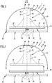
- the Figures 1 and 2 show an advantageous embodiment of an implant arrangement according to the invention, which is generally assigned the reference numeral 1.
- the implant arrangement 1 comprises a preferred embodiment of a packaging device according to the invention and an implant 12.
- the packaging device is identified as a whole with the reference numeral 10.
- the implant 12 is a tibial component 14 of a knee joint prosthesis.
- the tibial component 14 has a shaft 16 and a tibial plateau 18 in a manner known per se.
- the tibial component 14 has a coating at least in sections.
- the coating is applied on the outside and is not shown in the drawing.
- the shaft 16 can have the coating.
- the coating can in particular be osteointegrative in order to promote the growth of bone on the tibial component 14. Because of this, the implant 12 has a high degree of roughness in the area of the coating.
- the tibial component 14 is free of a coating in the present case.
- the packaging device 10 comprises a first packaging part 20 and a second packaging part 22, which in a packaging state ( Figure 1 ) define and delimit a receiving space 24 for the implant 12 between them.
- the packaging parts 20, 22 can be detachably connected to one another and, starting from a receiving state ( Figure 2 ), in which they are separated from one another, connected to one another and transferred to the packaging state. Starting from the packaging state, the packaging parts 20, 22 can be detached from one another and returned to the receiving state.
- the first packaging part 20 is formed in the shape of a hollow spherical cap and is manufactured, for example, as an injection-molded part, for example from a PETG film.
- the first packaging part can preferably be coated on the inside, facing the receiving space 24, at least in sections and preferably completely with an abrasion-resistant material.
- the abrasion-resistant material is preferably a thermoplastic material, in particular TPU.
- the first packaging part 20 has the shape of a hemisphere.
- the second packaging part 20 is essentially in the form of a plate.
- the second packaging part 22 forms a lid for the first packaging part 20 and can be connected to the first packaging part 20 via a connecting device 26.
- the connecting device 26 is a screw connection, the first packaging part 20 having an internal thread and the second packaging part 22 having an external thread.
- An actuating element 28 is provided on the second packaging part 22, designed as a grip element.
- the packaging part 22 can be gripped on the actuating element 28 for screwing it to the packaging part 20 or for releasing the screw connection.
- the packaging device 10 as a whole, apart from the actuating element 28, is inherently rotationally symmetrical with respect to an axis of symmetry 29.
- the axis of symmetry 29 runs through the pole of the hollow spherical cap formed by the first packaging part 20.
- the packaging device 10 comprises a receiving element 30 and a support element 32.
- the receiving element 30 is formed in the present case in the form of a cap 34.
- the cap 34 is formed separately from the first packaging part 20 and is fixed to it, for example by a force fit, form fit and / or material fit.
- the receiving element 30 defines an axis which in the present case coincides with the axis of symmetry 29.
- the receiving element 30 is made of an abrasion-resistant material, in particular a thermoplastic elastomer, especially TPU.
- the receiving element 30 is produced by deep drawing.
- the receiving element 30 serves to receive a first implant section 36 of the tibial component 14 that has the osteointegrative coating.
- the first implant section 36 is a section of the shaft 16 facing away from the tibial plateau 18.
- the receiving element 30 forms a recess 38 in which the first implant section 36 engages.
- the receiving element 30 comprises an edge 40 surrounding the first implant section 36.
- the receiving element 30 preferably overlaps the implant section 36 in a form-fitting manner.
- an axis defined by the shaft 16 coincides with the axis of the receiving element 30 and thus with the axis of symmetry 29.
- Manufacturing the receiving element 30 from an abrasion-resistant material reduces the risk of particles being detached as a result of contact with the coating of the shaft 16 and contamination of the implant 12.
- the support element 32 is designed essentially in the form of a plate and in the present case has the shape of a plate 42.
- the tibial component 14 can rest on the support element 32 with the tibial plateau 18 that forms a second implant section 44.
- the support element 32 forms a contact element for this purpose.
- the support element 32 comprises a recess 46 into which the tibial plateau 18 can engage.
- An edge 48 surrounds the second implant section 44.
- the support element 32 does not have a separate abrasion-resistant coating.
- this can be provided independently within the scope of the present invention. Complete production from abrasion-resistant material is also conceivable.
- the receiving element 30 and the supporting element 32 lie opposite one another in the receiving space 24 and are thereby spaced from one another.
- the implant 12 is arranged between the receiving element 30 and the support element 32.
- the receiving element 30 and the support element are axially opposite one another, based on the axis of symmetry 29.
- the receiving element 30 and the support element 32 lie directly opposite one another, wherein they are each aligned coaxially to the axis of symmetry 29.
- the implant 12 is in particular free of contact with the packaging parts 20 and 22 and is only in contact with the receiving element 30 and the support element 32.
- the support element 32 is fixed on the second packaging part 22 via a pretensioning element 50.
- the pretensioning element 50 is designed as a compression spring, in particular as a helical spring.
- the prestressing element 50 acts on the supporting element 32 with a force directed onto the receiving element 30, as a result of which the implant 12 is reliably fixed between the receiving element 30 and the supporting element 32.
- the prestressing force of the prestressing element 50 is aligned in the present case along the axis of symmetry 29.
- the prestressing element 50 is aligned coaxially to the axis of symmetry 29.
- prestressing element 50 is used.
- two or more prestressing elements are provided, which can preferably be arranged symmetrically relative to one another with respect to the axis of symmetry 29.
- the support element 32 comprises individual, spaced-apart, discrete support members 62.
- the support members 62 reduce the contact area of the support element 32 with the second implant section 44. The risk of any particle entry on the implant 12 is thereby reduced.
- the implant arrangement 65 with the packaging device 70 according to FIG Figure 4 In contrast to the packaging device 10, provision is made for a receptacle 72 for the receptacle element 30 to be present on the first packaging part 20.
- the packaging part 20 deviates from the otherwise hollow spherical cap-shaped shape.
- the receiving element 30 is in positive engagement with the receptacle 72. In this way, a particularly reliable fixing of the receiving element 30 on the first packaging part 20 can be achieved.
- the receiving part 30 further comprises a contact area 74 protruding from the edge 40, which rests in a flange-like manner on the packaging part 20 and can be connected to this, for example, by a force fit or material fit.
- support members 62 can likewise be provided on the support element 32.
Landscapes
- Health & Medical Sciences (AREA)
- Cardiology (AREA)
- Oral & Maxillofacial Surgery (AREA)
- Transplantation (AREA)
- Engineering & Computer Science (AREA)
- Biomedical Technology (AREA)
- Heart & Thoracic Surgery (AREA)
- Vascular Medicine (AREA)
- Life Sciences & Earth Sciences (AREA)
- Animal Behavior & Ethology (AREA)
- General Health & Medical Sciences (AREA)
- Public Health (AREA)
- Veterinary Medicine (AREA)
- Prostheses (AREA)
Abstract
Description
- Die vorliegende Erfindung betrifft eine Verpackungsvorrichtung für ein Implantat, insbesondere für ein eine Beschichtung aufweisendes Implantat.
- Die Verpackungsvorrichtung ist insbesondere für eine Tibiakomponente einer Kniegelenkprothese vorgesehen.
- Die vorliegende Erfindung betrifft ferner eine Implantatanordnung mit einem Implantat, insbesondere einer Tibiakomponente, und einer Verpackungsvorrichtung.
- Medizintechnische Produkte wie insbesondere Implantate werden für den Transport und die Bevorratung in Verpackungsvorrichtungen verpackt. Infolge des Fertigungsprozesses oder Kontakt mit der Verpackung kann die Gefahr bestehen, dass das Implantat mit möglicherweise schadhaften Partikeln belastet ist. Herstellungstechnisch kann dies zum Beispiel daran liegen, dass selbst Reinräume nicht vollständig partikelfrei sind. Transportbedingt können sich beispielsweise Partikel der Verpackung lösen und das Implantat kontaminieren.
- Es kann nicht ausgeschlossen werden, dass eine Kontaminierung des Implantates mit Partikeln postoperativ zu Beschwerden des Patienten führen kann und beispielsweise eine Lockerung des Implantates verursachen kann.
- Die
US 2008/0190805 A1 beschreibt eine Verpackungsvorrichtung für eine mit poröser Oberfläche versehene Tibiakomponente. Das Tibiaplateau ist in einem taschenartigen Aufnahmeelement der Verpackungsvorrichtung angeordnet und von diesem allseits umschlossen. Dies wirkt sich nicht nur nachteilig auf die Handhabung der Tibiakomponente aus. Beim Einsetzen in das Aufnahmeelement und beim Entnehmen aus dem Aufnahmeelement ist am Tibiaschaft anzugreifen. Es besteht das Risiko, dass der Schaft dabei kontaminiert wird. - Die
US 2018/0036092 A1 beschreibt eine Blister-Verpackung für einen medizintechnischen Artikel. Dabei ist der Artikel beispielsweise in einer Innenverpackung aufgenommen, die ihrerseits in einer Außenverpackung angeordnet ist. - Eine weitere Implantatverpackung für eine Tibiakomponente einer Knieprothese ist in der
CN 208326155 U beschrieben. - Aufgabe der vorliegenden Erfindung ist es, eine Verpackungsvorrichtung für ein Implantat und eine Implantatanordnung bereitzustellen, bei deren Einsatz eine höhere Patientensicherheit gewährleistet werden kann.
- Diese Aufgabe wird durch eine erfindungsgemäße Verpackungsvorrichtung für ein eine Beschichtung aufweisendes Implantat, insbesondere für eine Tibiakomponente einer Kniegelenkendoprothese gelöst, welche Verpackungsvorrichtung ein erstes Verpackungsteil und ein zweites Verpackungsteil umfasst, die in einem Verpackungszustand einen Aufnahmeraum zwischen sich definieren, im Aufnahmeraum ein an einem der Verpackungsteile angeordnetes Aufnahmeelement, in dem ein insbesondere die Beschichtung aufweisender erster Implantatabschnitt aufnehmbar ist, und im Aufnahmeraum ein im Abstand zum Aufnahmeelement angeordnetes Stützelement, das an einen zweiten Implantatabschnitt anlegbar ist, wobei das Aufnahmeelement und/oder das Stützelement, zumindest abschnittsweise und bevorzugt vollständig, aus einem für die Beschichtung des Implantates abriebresistenten Material gefertigt sind oder eine abriebresistente Beschichtung aufweisen, und wobei das Aufnahmeelement und das Stützelement im Aufnahmeraum einander gegenüberliegend positioniert sind, zum Anlegen an zwei einander abgewandte Implantatabschnitte des Implantates.
- Die erfindungsgemäße Verpackungsvorrichtung ist insbesondere vorgesehen für ein zumindest teilweise mit einer Beschichtung versehenes Implantat. Hierbei kann es sich insbesondere um eine Tibiakomponente einer Kniegelenkprothese handeln. Die Erfindung ist jedoch nicht hierauf beschränkt. Die Verpackungsvorrichtung kann auch mit andersartigen Implantaten zum Einsatz kommen. Bekannt sind beispielsweise poröse, osteointegrative Beschichtungen, die das Anwachsen des Knochens am Implantat fördern. Eine derartige Beschichtung weist typischerweise eine hohe Porosität auf, und es besteht eine Gefahr erhöhten Abriebs der Beschichtung mit der Verpackungsvorrichtung.
- Gemäß der vorliegenden Erfindung ist ein Aufnahmeelement an einem Verpackungsteil und ein Stützelement vorgesehen, die im Aufnahmeraum angeordnet sind. Ein erster Implantatabschnitt, der insbesondere die Beschichtung aufweist, kann im Aufnahmeteil aufgenommen werden. Ein zweiter Implantatabschnitt kann an das im Abstand dazu angeordnete Stützelement angelegt werden. Dies erlaubt es, das Implantat, insbesondere die Tibiakomponente, zuverlässig im Aufnahmeraum zu halten und den Kontakt mit den übrigen Komponenten der Verpackungsvorrichtung zu verringern und vorteilhaft zu eliminieren. Das Aufnahmeelement und/oder das Stützelement ist mit einem abriebresistenten Material beschichtet oder aus einem solchen gefertigt. Hierunter ist vorliegend insbesondere zu verstehen, dass die abriebresistente Beschichtung bei Kontakt mit dem Implantat und insbesondere dessen Beschichtung einer lediglich geringen Gefahr des Abriebs unterliegt und vorzugsweise ein Abrieb vollständig oder im Wesentlichen vollständig vermieden werden kann. Dies verringert die Gefahr einer Kontaminierung des Implantates und steigert die Patientensicherheit.
- Es kann vorgesehen sein, dass nur das Aufnahmeelement oder nur das Stützelement die abriebresistente Beschichtung aufweist oder aus dieser gefertigt sind.
- Vorgesehen ist, dass das Aufnahmeelement und das Stützelement im Aufnahmeraum einander gegenüberliegend positioniert sind, zum Anlegen an zwei einander abgewandte Implantatabschnitte des Implantates. Dabei ist das Implantat vorzugsweise zwischen dem Aufnahmeelement und dem Stützelement positioniert.
- Das Aufnahmeelement und das Stützelement liegen einander im Aufnahmeraum beispielsweise unmittelbar gegenüber.
- Das Aufnahmeelement und das Stützelement bilden vordefinierte Schnittstellen für die Implantatabschnitte. Im Fall einer Tibiakomponente kann insbesondere deren Schaft im Aufnahmeelement aufgenommen werden, und das Tibiaplateau kann am Stützelement angelegt werden.
- Von Vorteil ist es, wenn das erste Verpackungsteil und das zweite Verpackungsteil frei von Kontakt mit dem Implantat sind und das Implantat, von den Komponenten der Verpackungseinrichtung, nur mit dem Aufnahmeelement und dem Stützelement in Kontakt steht. Ein Abrieb von Material der Verpackungsteile lässt sich dadurch vermeiden und die Patientensicherheit erhöhen.
- Als vorteilhaft kann es sich erweisen, wenn die Verpackungsvorrichtung in sich rotationssymmetrisch oder im Wesentlichen rotationssymmetrisch bezüglich einer Symmetrieachse ausgebildet ist. Eine derartige Symmetrie kann beispielsweise vorgesehen sein, wenn, wie nachfolgend erläutert, ein Verpackungsteil zumindest näherungsweise die Gestalt einer Hohlkugelkalotte aufweist und das zweite Verpackungsteil beispielsweise eine plattenförmige Gestalt. Die Symmetrieachse kann beispielsweise quer und insbesondere senkrecht zu einer vom zweiten Verpackungsteil definierten Ebene ausgerichtet sein.
- Beispielsweise kann vorgesehen sein, dass das Aufnahmeelement und das Stützelement axial, bezogen auf die vorstehend genannte Symmetrieachse, einander gegenüberliegend im Aufnahmeraum positioniert sind.
- Günstig ist es, wenn die Verpackungsvorrichtung mindestens ein Vorspannelement umfasst, das das Stützelement mit einer auf das Aufnahmeelement gerichteten Vorspannkraft beaufschlagt. Dies bietet den Vorteil, das Implantat an den relativ zueinander vorgespannten Komponenten - Aufnahmeelement und Stützelement - zuverlässig zu halten. Vorteilhafterweise besteht der Vorteil, eine Mehrzahl von Implantaten unterschiedlicher Größe mit der Verpackungsvorrichtung zu verpacken, wobei die Vorspannkraft eine jeweilige Anpassung der Relativstellung beider Komponenten erlaubt. Bei kleineren Implantaten weisen das Aufnahmeelement und das Stützelement einen geringeren Abstand voneinander auf als bei größeren Implantaten, zu deren Aufnahme das Aufnahmeelement und das Stützelement entgegen der Vorspannkraft voneinander wegbewegt werden können.
- Das mindestens eine Vorspannelement kann zum Beispiel eine Druckfeder sein, insbesondere eine Schraubenfeder.
- Die Vorspannkraft kann beispielsweise entlang einer Achse der Verpackungsvorrichtung, insbesondere der Symmetrieachse, und/oder entlang einer Achse des Implantates ausgerichtet sein. Beispielsweise ist das mindestens eine Vorspannelement entlang der Achse der Verpackungsvorrichtung und/oder entlang der Achse des Implantates ausgerichtet. Alternativ dazu kann mindestens ein Vorspannelement parallel zur Achse der Verpackungsvorrichtung und/oder parallel zur Achse des Implantates ausgerichtet sein. Die Achse des Implantates ist beispielsweise im Fall einer Tibiakomponente durch den Tibiaschaft definiert.
- Die Achse der Verpackungsvorrichtung kann beispielsweise eine vom Aufnahmeelement definierte Achse sein. Vorgesehen sein kann, dass die Verpackungsvorrichtung eine Mehrzahl von Vorspannelementen umfasst.
- Das mindestens eine Vorspannelement ist beispielsweise am zweiten Verpackungsteil festgelegt. Insbesondere kann das Vorspannelement zwischen dem zweiten Verpackungsteil und dem Stützelement angeordnet sein. Über das Vorspannelement kann das Stützelement mit dem zweiten Verpackungsteil verbunden sein.
- Vorgesehen sein kann, dass das mindestens eine Vorspannelement am ersten Verpackungsteil festgelegt ist. Beispielsweise kann das Vorspannelement zwischen dem ersten Verpackungsteil und dem Aufnahmeelement angeordnet sein. Über das Vorspannelement kann das Aufnahmeelement mit dem ersten Verpackungsteil verbunden sein.
- Bei einer andersartigen vorteilhaften Ausführungsform kann vorgesehen sein, dass das Aufnahmeelement unmittelbar am ersten Verpackungsteil festgelegt ist, ohne dazwischen angeordnetes Vorspannelement.
- Vorgesehen sein kann, dass das Stützelement unmittelbar am zweiten Verpackungsteil festgelegt ist, ohne dazwischen angeordnetes Vorspannelement.
- Vorgesehen sein kann, dass das Aufnahmeelement getrennt vom ersten Verpackungsteil gebildet und an diesem unmittelbar oder mittelbar festgelegt ist.
- Alternativ kann das Aufnahmeelement vom ersten Verpackungsteil gebildet oder von diesem umfasst sein.
- In entsprechender Weise kann es vorteilhaft sein, wenn das Stützelement getrennt vom zweiten Verpackungsteil gebildet und an diesem unmittelbar oder mittelbar festgelegt ist.
- Alternativ kann das Stützelement vom zweiten Verpackungsteil gebildet oder von diesem umfasst sein.
- Eine Festlegung oder Verbindung des Aufnahmeelementes und/oder des Stützelementes an bzw. mit einem jeweiligen Verpackungsteil kann auf alle möglichen Weisen erfolgen, insbesondere durch Formschluss, Kraftschluss und/oder Stoffschluss. Die Verbindung kann direkt oder indirekt sein. Vorgesehen sein kann bei einer bevorzugten Ausführungsform, dass das Aufnahmeteil mit Formschluss an das erste Verpackungsteil angelegt oder an dieses angespritzt ist. Das Stützelement kann beispielsweise über das vorstehend genannte Vorspannelement mit dem zweiten Verpackungsteil verbunden sein.
- Die Fertigung des Aufnahmeelementes, des Stützelementes und/oder der Verpackungsteile kann auf unterschiedliche Weisen erfolgen. Die Verpackungsteile sind beispielsweise Spritzgussteile. Das Aufnahmeelement und/oder das Stützelement kann beispielsweise durch Spritzguss und/oder durch Tiefziehen hergestellt werden.
- Das abriebresistente Material kann beispielsweise ein thermoplastisches Elastomer sein, insbesondere ein thermoplastisches Elastomer auf Urethanbasis (TPU). Andersartige geeignete thermoplastische Elastomere sind beispielsweise TPA (Thermoplastische Polyamidelastomere), TPC (Thermoplastische Copolyesterelastomere), TPO (Thermoplastische Elastomere auf Olefinbasis) oder TPV (Thermoplastische Vulkanisate oder vernetzte thermoplastische Elastomere auf Olefinbasis).
- Bei einer bevorzugten Ausführungsform ist das Aufnahmeelement und/oder das Stützelement beispielsweise ein Tiefziehteil aus einer TPU-Folie oder ein Spritzgussteil aus TPU.
- Das abriebresistente Material kann beispielsweise ein Polylactidmaterial (PLA) sein, im Hinblick auf eine Biokompatibilität des Materials.
- Insbesondere kann vorzugsweise ein biokompatibles abriebrestistentes Material vorgesehen sein. Sollte Abrieb entstehen und sollten sich Partikel am Implantat anlagern, können diese im Körper resorbiert werden.
- Günstig kann es sein, wenn das erste Verpackungsteil und/oder das zweite Verpackungsteil aus einem Material mit mindestens einer der folgenden Eigenschaften bestehen oder ein solches Material umfassen:
- gefertigt aus PP, PE und/oder PEEK;
- gefertigt aus einem beta- und/oder gammasterilisierbaren Material;
- gefertigt aus oder beschichtet mit einem abriebresistenten Material, beispielsweise einem der vorstehend genannten abriebresistenten Materialien.
- Günstigerweise kann zum Beispiel vorgesehen sein, dass mindestens eines der Verpackungsteile dem Aufnahmeraum zugewandt eine abriebresistente Beschichtung aufweist. Die Gefahr eines Partikeleintrags auf das Implantat kann dadurch weiter reduziert werden.
- Vorteilhaft kann es sein, wenn das Stützelement ein flächiges Anlageelement umfasst oder ausbildet zum flächigen Anliegen am zweiten Implantatabschnitt. Beispielsweise ist das Stützelement plattenförmig und geeignet zum flächigen Anliegen an einem flächigen Tibiaplateau einer Tibiakomponente.
- Alternativ kann vorgesehen sein, dass das Stützelement eine Mehrzahl von diskreten, voneinander beabstandeten Stützgliedern zum jeweiligen Anlegen an den zweiten Implantatabschnitt umfasst. Dadurch kann die Kontaktfläche zwischen dem Implantatabschnitt und dem Stützelement verringert werden, um der Gefahr eines etwaigen Abriebs entgegenzuwirken.
- Günstig kann es sein, wenn das Aufnahmeelement und/oder das Stützelement eine jeweilige Ausnehmung umfassen oder bilden, in die der erste Implantatabschnitt bzw. der zweite Implantatabschnitt eingreift und die einen Rand aufweist, der den ersten Implantatabschnitt bzw. den zweiten Implantatabschnitt bevorzugt vollständig umgibt. Beispielsweise kann ein jeweiliger Implantatabschnitt formschlüssig oder im Wesentlichen formschlüssig in das Aufnahmeelement bzw. das Stützelement eingreifen.
- Das Aufnahmeelement kann zum Beispiel als Kappe oder Hülse ausgestaltet sein.
- Das Stützelement kann zum Beispiel plattenförmig mit einem umlaufenden Rand ausgestaltet sein, wobei der Rand zum Beispiel in Richtung des Aufnahmeelementes absteht.
- Günstig ist es, wenn das erste Verpackungsteil und das zweite Verpackungsteil lösbar miteinander verbindbar sind. Beispielsweise nehmen die Verpackungsteile einen Aufnahmezustand ein, indem sie voneinander gelöst sind und indem das Implantat am Aufnahmeelement oder am Stützelement angelegt wird. Ausgehend vom Aufnahmezustand können die Verpackungsteile miteinander verbunden und in den Verpackungszustand überführt werden.
- Die Verpackungsteile können zum Beispiel mittels einer Schraubverbindung miteinander verbunden werden. Die Schraubverbindung kann insbesondere zum passgenauen Fixieren des Implantats zwischen dem Aufnahmeelement und dem Stützelement fixiert werden, wobei vorzugsweise entgegen der Wirkung des vorstehend genannten Vorspannelementes auf die Verpackungsteile eingewirkt wird.
- Ein Betätigungselement an mindestens einem Verpackungsteil, zum Beispiel in Gestalt eines Griffelementes, kann zum Verschrauben vorgesehen sein.
- Das erste und/oder das zweite Verpackungsteil können zumindest abschnittsweise aus einem transparenten Material gefertigt sein.
- Vorgesehen sein kann, dass das erste Verpackungsteil, zumindest näherungsweise, die Gestalt einer Hohlkugelkalotte aufweist, speziell in Halbkugelform. Das zweite Verpackungsteil kann beispielsweise eine im Wesentlichen plattenförmige Gestalt aufweisen zum Schließen des von der Hohlkugelkalotte überfangenen Aufnahmeraumes.
- Das zweite Verpackungsteil kann beispielsweise als Deckel zum Verschließen des ersten Verpackungsteils ausgebildet sein. Der Deckel kann zum Beispiel eine Ebene definieren, quer und insbesondere senkrecht zu dem eine Achse der Verpackungseinrichtung definiert ist, insbesondere eine Symmetrieachse.
- Wie eingangs erwähnt, betrifft die vorliegende Erfindung auch eine Implantatanordnung.
- Eine die eingangs genannte Aufgabe lösende erfindungsgemäße Implantatanordnung umfasst ein Implantat mit einem ersten Implantatabschnitt und einem zweiten Implantatabschnitt sowie eine Verpackungsvorrichtung der vorstehend beschriebenen Art, wobei das Implantat in einem Verpackungszustand der Verpackungsvorrichtung im Aufnahmeraum aufgenommen ist, wobei der erste Implantatabschnitt im Aufnahmeelement aufgenommen ist und das Stützelement am zweiten Implantatabschnitt anliegt.
- Die Vorteile, die bereits im Zusammenhang mit der Erläuterung der erfindungsgemäßen Verpackungsvorrichtung erwähnt wurden, können bei der Implantatanordnung ebenfalls erzielt werden. Diesbezüglich kann auf die voranstehenden Ausführungen verwiesen werden.
- Vorteilhafte Ausführungsformen der erfindungsgemäßen Implantatanordnung ergeben sich durch vorteilhafte Ausführungsformen der erfindungsgemäßen Verpackungsvorrichtung. Diesbezüglich wird auf die voranstehenden Ausführungen verwiesen.
- Das Implantat kann insbesondere eine Tibiakomponente einer Kniegelenkprothese sein, die einen Tibiaschaft und ein Tibiaplateau umfasst, wobei der Tibiaschaft den ersten Implantatabschnitt umfasst oder bildet und wobei das Tibiaplateau den zweiten Implantatabschnitt umfasst oder bildet.
- Die nachfolgende Beschreibung einer bevorzugten Ausführungsform der Erfindung dient im Zusammenhang mit der Zeichnung der näheren Erläuterung der Erfindung. Es zeigen:
- Figur 1:
- eine Implantatanordnung und eine Verpackungsvorrichtung gemäß der vorliegenden Erfindung zum Verpacken einer Tibiakomponente, wobei Verpackungsteile einen Verpackungszustand einnehmen, jeweils in bevorzugter Ausführungsform;
- Figur 2:
- die Implantatanordnung aus
Figur 1 , wobei die Verpackungsteile einen Aufnahmezustand einnehmen; - Figur 3:
- eine Darstellung entsprechend
Figur 2 bei jeweiligen zweiten bevorzugten Ausführungsformen der Erfindung; und - Figur 4:
- eine Darstellung entsprechend
Figur 2 bei jeweiligen dritten bevorzugten Ausführungsformen der Erfindung. - Die
Figuren 1 und 2 zeigen eine insgesamt mit dem Bezugszeichen 1 belegte vorteilhafte Ausführungsform einer erfindungsgemäßen Implantatanordnung. Die Implantatanordnung 1 umfasst eine bevorzugte Ausführungsform einer erfindungsgemäßen Verpackungsvorrichtung sowie ein Implantat 12. Die Verpackungsvorrichtung ist insgesamt mit dem Bezugszeichen 10 gekennzeichnet. Bei dem Implantat 12 handelt es sich vorliegend um eine Tibiakomponente 14 einer Kniegelenkprothese. Die Tibiakomponente 14 weist in an sich bekannter Weise einen Schaft 16 und ein Tibiaplateau 18 auf. - Im vorliegenden Fall ist insbesondere vorgesehen, dass die Tibiakomponente 14 zumindest abschnittsweise eine Beschichtung aufweist. Die Beschichtung ist außenseitig aufgebracht und in der Zeichnung nicht dargestellt. Insbesondere kann der Schaft 16 die Beschichtung aufweisen.
- Die Beschichtung kann insbesondere osteointegrativ sein, um das Anwachsen von Knochen an der Tibiakomponente 14 zu begünstigen. Aufgrund dessen weist das Implantat 12 im Bereich der Beschichtung eine hohe Rauheit auf.
- Am Tibiaplateau 18 ist die Tibiakomponente 14 vorliegend frei von einer Beschichtung.
- Die Verpackungsvorrichtung 10 umfasst ein erstes Verpackungsteil 20 und ein zweites Verpackungsteil 22, die in einem Verpackungszustand (
Figur 1 ) einen Aufnahmeraum 24 für das Implantat 12 zwischen sich definieren und begrenzen. - Die Verpackungsteile 20, 22 sind lösbar miteinander verbindbar und können ausgehend von einem Aufnahmezustand (
Figur 2 ), in dem sie voneinander getrennt sind, miteinander verbunden und in den Verpackungszustand überführt werden. Ausgehend vom Verpackungszustand können die Verpackungsteile 20, 22 voneinander gelöst und wieder in den Aufnahmezustand überführt werden. - Das erste Verpackungsteil 20 ist im vorliegenden Fall hohlkugelkalottenförmig gebildet und beispielsweise als Spritzgussteil gefertigt, zum Beispiel aus einer PETG-Folie. Vorzugsweise kann das erste Verpackungsteil innenseitig, dem Aufnahmeraum 24 zugewandt, zumindest abschnittsweise und bevorzugt vollständig mit einem abriebresistenten Material beschichtet sein. Das abriebresistente Material ist vorzugsweise ein thermoplastisches Material, insbesondere TPU.
- Das erste Verpackungsteil 20 weist die Gestalt einer Halbkugel auf. Das zweite Verpackungsteil 20 ist im Wesentlichen von plattenförmiger Gestalt. Das zweite Verpackungsteil 22 bildet einen Deckel für das erste Verpackungsteil 20 und kann über eine Verbindungseinrichtung 26 mit dem ersten Verpackungsteil 20 verbunden werden. Vorliegend ist die Verbindungseinrichtung 26 eine Schraubverbindung, wobei das erste Verpackungsteil 20 ein Innengewinde und das zweite Verpackungsteil 22 ein Außengewinde aufweist.
- Am zweiten Verpackungsteil 22 ist ein Betätigungselement 28 vorgesehen, ausgestaltet als Griffelement. Am Betätigungselement 28 kann das Verpackungsteil 22 zum Verschrauben mit dem Verpackungsteil 20 oder zum Lösen der Schraubverbindung ergriffen werden.
- Die Verpackungsvorrichtung 10 ist insgesamt, abgesehen vom Betätigungselement 28, in sich rotationssymmetrisch bezüglich einer Symmetrieachse 29. Die Symmetrieachse 29 ist vorliegend quer und insbesondere senkrecht zu einer vom Verpackungsteil 22 definierten Ebene ausgerichtet. Die Symmetrieachse 29 verläuft durch den Pol der vom ersten Verpackungsteil 20 gebildeten Hohlkugelkalotte.
- Die Verpackungsvorrichtung 10 umfasst ein Aufnahmeelement 30 und ein Stützelement 32. Das Aufnahmeelement 30 ist vorliegend in Form einer Kappe 34 gebildet. Die Kappe 34 ist gesondert vom ersten Verpackungsteil 20 gebildet und an diesem festgelegt, zum Beispiel durch Kraftschluss, Formschluss und/oder Stoffschluss.
- Das Aufnahmeelement 30 definiert eine Achse, die vorliegend mit der Symmetrieachse 29 zusammenfällt.
- Das Aufnahmeelement 30 ist aus einem abriebresistenten Material gefertigt, insbesondere einem thermoplastischen Elastomer, speziell aus TPU. Beispielsweise ist das Aufnahmeelement 30 durch Tiefziehen hergestellt.
- Das Aufnahmeelement 30 dient zum Aufnehmen eines die osteointegrative Beschichtung aufweisenden ersten Implantatabschnittes 36 der Tibiakomponente 14. Der erste Implantatabschnitt 36 ist ein dem Tibiaplateau 18 abgewandter Abschnitt des Schaftes 16.
- Das Aufnahmeelement 30 bildet eine Ausnehmung 38, in der der erste Implantatabschnitt 36 eingreift. Darüber hinaus umfasst das Aufnahmeelement 30 einen den ersten Implantatabschnitt 36 umgebenden Rand 40. Vorzugsweise übergreift das Aufnahmeelement 30 den Implantatabschnitt 36 formschlüssig.
- Eine vom Schaft 16 definierte Achse fällt vorliegend mit der Achse des Aufnahmeelementes 30 und damit mit der Symmetrieachse 29 zusammen.
- Durch die Fertigung des Aufnahmeelementes 30 aus einem abriebresistenten Material ist die Gefahr verringert, dass Partikel infolge des Kontaktes mit der Beschichtung des Schaftes 16 abgelöst werden und zu einer Kontamination des Implantates 12 führen.
- Das Stützelement 32 ist im Wesentlichen plattenförmig ausgestaltet und im vorliegenden Fall von der Gestalt eines Tellers 42. Die Tibiakomponente 14 kann mit dem einen zweiten Implantatabschnitt 44 bildenden Tibiaplateau 18 am Stützelement 32 anliegen. Das Stützelement 32 bildet hierfür ein Anlageelement. Insbesondere umfasst das Stützelement 32 eine Ausnehmung 46, in die das Tibiaplateau 18 eingreifen kann. Ein Rand 48 umgibt den zweiten Implantatabschnitt 44.
- Vorliegend weist das Stützelement 32 keine gesonderte abriebresistente Beschichtung auf. Dies kann jedoch im Rahmen der vorliegenden Erfindung selbstständig vorgesehen sein. Auch eine vollständige Fertigung aus abriebresistentem Material ist denkbar.
- Das Aufnahmeelement 30 und das Stützelement 32 liegen einander im Aufnahmeraum 24 gegenüber und sind dadurch voneinander beabstandet. Das Implantat 12 ist zwischen dem Aufnahmeelement 30 und dem Stützelement 32 angeordnet.
- Im vorliegenden Fall liegen das Aufnahmeelement 30 und das Stützelement einander axial, bezogen auf die Symmetrieachse 29, gegenüber. Insbesondere liegen das Aufnahmeelement 30 und das Stützelement 32 einander unmittelbar gegenüber, wobei sie jeweils koaxial zur Symmetrieachse 29 ausgerichtet sind.
- Das Implantat 12 ist insbesondere frei von Kontakt mit den Verpackungsteilen 20 und 22 und steht nur mit dem Aufnahmeelement 30 und dem Stützelement 32 in Kontakt.
- Das Stützelement 32 ist über ein Vorspannelement 50 am zweiten Verpackungsteil 22 festgelegt. Das Vorspannelement 50 ist als Druckfeder ausgestaltet, insbesondere als Schraubenfeder. Das Vorspannelement 50 beaufschlagt das Stützelement 32 mit einer auf das Aufnahmeelement 30 gerichteten Kraft, wodurch das Implantat 12 zuverlässig zwischen dem Aufnahmeelement 30 und dem Stützelement 32 fixiert ist.
- Die Vorspannkraft des Vorspannelementes 50 ist vorliegend entlang der Symmetrieachse 29 ausgerichtet. Das Vorspannelement 50 ist koaxial zur Symmetrieachse 29 ausgerichtet.
- Vorgesehen sein kann, dass mehr als nur ein Vorspannelement 50 zum Einsatz kommt. Beispielsweise sind zwei oder mehr Vorspannelemente vorgesehen, die vorzugsweise symmetrisch relativ zueinander bezüglich der Symmetrieachse 29 angeordnet sein können.
- Darüber hinaus besteht die Möglichkeit, Implantate 12 unterschiedlicher Größe in der Verpackungsvorrichtung 10 zu fixieren. Die jeweilige Anpassung an die Größe erfolgt unter der Wirkung des Vorspannelementes 50.
- Nachfolgend wird auf in den
Figuren 3 und 4 in einer derFigur 2 entsprechenden Weise dargestellte bevorzugte Ausführungsformen der erfindungsgemäßen Implantatanordnung und der erfindungsgemäßen Verpackungsvorrichtung eingegangen. Die im Zusammenhang mit der Implantatanordnung 1 und der Verpackungsvorrichtung 10 erwähnten Vorteile können mit diesen Verpackungsvorrichtungen ebenfalls erzielt werden, so dass diesbezüglich auf die voranstehenden Ausführungen verwiesen wird. Es werden lediglich die wesentlichsten Unterschiede erläutert. - Bei einer Implantatanordnung 55 mit einer Verpackungsvorrichtung 60 gemäß
Figur 3 umfasst das Stützelement 32 einzelne, voneinander beabstandete diskrete Stützglieder 62. Die Stützglieder 62 verringern die Kontaktfläche des Stützelementes 32 mit dem zweiten Implantatabschnitt 44. Die Gefahr eines etwaigen Partikeleintrags am Implantat 12 wird dadurch verringert. - Die Implantatanordnung 65 mit der Verpackungsvorrichtung 70 gemäß
Figur 4 sieht abweichend von der Verpackungsvorrichtung 10 vor, dass am ersten Verpackungsteil 20 eine Aufnahme 72 für das Aufnahmeelement 30 vorhanden ist. In der Aufnahme 72 weicht das Verpackungsteil 20 von der ansonsten hohlkugelkalottenförmigen Gestalt ab. Das Aufnahmeelement 30 steht in formschlüssigem Eingriff mit der Aufnahme 72. Auf diese Weise kann eine besonders zuverlässige Fixierung des Aufnahmeelementes 30 am ersten Verpackungsteil 20 erzielt werden. - Das Aufnahmeteil 30 umfasst ferner einen vom Rand 40 abstehenden Anlagebereich 74, der flanschartig am Verpackungsteil 20 anliegt und mit diesem zum Beispiel durch Kraftschluss oder Stoffschluss verbunden sein kann.
- Es versteht sich, dass bei der Verpackungsvorrichtung 70 ebenfalls Stützglieder 62 am Stützelement 32 vorgesehen sein können.
-
- 1
- Implantatanordnung
- 10
- Verpackungsvorrichtung
- 12
- Implantat
- 14
- Tibiakomponente
- 16
- Schaft
- 18
- Tibiaplateau
- 20
- erstes Verpackungsteil
- 22
- zweites Verpackungsteil
- 24
- Aufnahmeraum
- 26
- Verbindungseinrichtung
- 28
- Betätigungselement
- 29
- Symmetrieachse
- 30
- Aufnahmeelement
- 32
- Stützelement
- 34
- Kappe
- 36
- erster Implantatabschnitt
- 38
- Ausnehmung
- 40
- Rand
- 42
- Teller
- 44
- zweiter Implantatabschnitt
- 46
- Ausnehmung
- 48
- Rand
- 50
- Vorspannelement
- 55
- Implantatanordnung
- 60
- Verpackungsvorrichtung
- 62
- Stützglied
- 65
- Implantatanordnung
- 70
- Verpackungsvorrichtung
- 72
- Aufnahme
- 74
- Anlagebereich
Claims (15)
- Verpackungsvorrichtung für ein eine Beschichtung aufweisendes Implantat (12), insbesondere für eine Tibiakomponente (14) einer Kniegelenkprothese, welche Verpackungsvorrichtung (10; 60; 70) ein erstes Verpackungsteil (20) und ein zweites Verpackungsteil (22) umfasst, die in einem Verpackungszustand einen Aufnahmeraum (24) zwischen sich definieren, im Aufnahmeraum (24) ein an einem der Verpackungsteile (20, 22) angeordnetes Aufnahmeelement (30), in dem ein insbesondere die Beschichtung aufweisender erster Implantatabschnitt (36) aufnehmbar ist, und im Aufnahmeraum (24) ein im Abstand zum Aufnahmeelement (30) angeordnetes Stützelement (32), das an einen zweiten Implantatabschnitt (44) anlegbar ist, wobei das Aufnahmeelement (30) und/oder das Stützelement (32), zumindest abschnittsweise und bevorzugt vollständig, aus einem für die Beschichtung des Implantates (12) abriebresistenten Material gefertigt sind oder eine abriebresistente Beschichtung aufweisen, und wobei das Aufnahmeelement (30) und das Stützelement (32) im Aufnahmeraum (24) einander gegenüberliegend positioniert sind, zum Anlegen an zwei einander abgewandte Implantatabschnitte (36, 44) des Implantates.
- Verpackungsvorrichtung nach Anspruch 1, dadurch gekennzeichnet, dass das erste Verpackungsteil (20) und das zweite Verpackungsteil (22) frei von Kontakt mit dem Implantat (12) sind und das Implantat (12), von den Komponenten der Verpackungsvorrichtung (10; 60; 70), nur mit dem Aufnahmeelement (30) und dem Stützelement (32) in Kontakt steht.
- Verpackungsvorrichtung nach einem der voranstehenden Ansprüche,
dadurch gekennzeichnet, dass die Verpackungsvorrichtung (10; 60; 70) in sich rotationssymmetrisch oder im Wesentlichen rotationssymmetrisch bezüglich einer Symmetrieachse (29) ausgebildet ist. - Verpackungsvorrichtung nach Anspruch 3, dadurch gekennzeichnet, dass das Aufnahmeelement (30) und das Stützelement (32) axial, bezogen auf die Symmetrieachse (29) einander gegenüberliegend im Aufnahmeraum (24) positioniert sind.
- Verpackungsvorrichtung nach einem der voranstehenden Ansprüche,
dadurch gekennzeichnet, dass die Verpackungsvorrichtung (10; 60; 70) mindestens ein Vorspannelement (50) umfasst, das das Stützelement (32) mit einer auf das Aufnahmeelement (30) gerichteten Vorspannkraft beaufschlagt, wobei das mindestens eine Vorspannelement (50) vorzugsweise als Druckfeder ausgestaltet ist, insbesondere als Schraubenfeder. - Verpackungsvorrichtung nach Anspruch 5, dadurch gekennzeichnet, dass die Vorspannkraft entlang einer von der Verpackungsvorrichtung (10; 60; 70) definierten Achse, insbesondere einer Symmetrieachse (29), und/oder entlang einer Achse des Implantates (12) ausgerichtet ist.
- Verpackungsvorrichtung nach einem der voranstehenden Ansprüche,
dadurch gekennzeichnet, dass zumindest eines der Folgenden gilt:- das Aufnahmeelement (30) ist getrennt vom ersten Verpackungsteil (20) gebildet und an diesem festgelegt, und/oder das Stützelement (32) ist getrennt vom zweiten Verpackungsteil (22) gebildet und an diesem festgelegt;- das Aufnahmeelement (30) ist vom ersten Verpackungsteil (20) gebildet oder von diesem umfasst und/oder das Stützelement (32) ist vom zweiten Verpackungsteil (22) gebildet oder von diesem umfasst. - Verpackungsvorrichtung nach einem der voranstehenden Ansprüche, dadurch gekennzeichnet, dass das abriebresistente Material eines der Folgenden ist oder umfasst:- ein thermoplastisches Elastomer, insbesondere ein thermoplastisches Elastomer auf Urethanbasis (TPU);- ein Polylactidmaterial (PLA);- ein biokompatibles Material.
- Verpackungsvorrichtung nach einem der voranstehenden Ansprüche, dadurch gekennzeichnet, dass das erste Verpackungsteil (20) und/oder das zweite Verpackungsteil (22) aus einem Material mit mindestens einer der folgenden Eigenschaften bestehen oder ein solches Material umfassen:- gefertigt aus PP, PE und/oder PEEK;- gefertigt aus einem beta- und/oder gammasterilisierbaren Material;- gefertigt aus oder beschichtet mit einem abriebresistenten Material.
- Verpackungsvorrichtung nach einem der voranstehenden Ansprüche, dadurch gekennzeichnet, dass das Stützelement (32) ein flächiges Anlageelement umfasst oder ausbildet zum flächigen Anliegen am zweiten Implantatabschnitt (44) oder dass das Stützelement (32) eine Mehrzahl von diskreten, voneinander beabstandeten Stützgliedern (62) zum jeweiligen Anlegen an den zweiten Implantatabschnitt (44) umfasst.
- Verpackungsvorrichtung nach einem der voranstehenden Ansprüche, dadurch gekennzeichnet, dass das Aufnahmeelement (30) und/oder das Stützelement (32) eine jeweilige Ausnehmung (38, 46) umfassen oder bilden, in die der erste Implantatabschnitt (36) bzw. der zweite Implantatabschnitt (44) eingreift und die einen Rand (40, 48) aufweist, der den ersten Implantatabschnitt (36) bzw. den zweiten Implantatabschnitt (44) bevorzugt vollständig umgibt.
- Verpackungsvorrichtung nach einem der voranstehenden Ansprüche, dadurch gekennzeichnet, dass das erste Verpackungsteil (20) und das zweite Verpackungsteil (22) lösbar miteinander verbindbar sind, vorzugsweise mittels einer Schraubverbindung, wobei insbesondere ein Betätigungselement (28) an mindestens einem der Verpackungsteile (20, 22) angeordnet ist.
- Verpackungsvorrichtung nach einem der voranstehenden Ansprüche, dadurch gekennzeichnet, dass zumindest eines der Folgenden gilt:- das erste Verpackungsteil (20) und/oder das zweite Verpackungsteil (22) ist zumindest abschnittsweise aus einem transparenten Material gefertigt;- das erste Verpackungsteil (20) weist, zumindest näherungsweise, die Gestalt einer Hohlkugelkalotte auf, und das zweite Verpackungsteil (22) weist eine im Wesentlichen plattenförmige Gestalt auf zum Schließen des von der Hohlkugelkalotte überfangenen Aufnahmeraumes (24).
- Implantatanordnung, umfassend ein Implantat (12) mit einem ersten Implantatabschnitt (36) und einem zweiten Implantatabschnitt (44) sowie eine Verpackungsvorrichtung (10;60; 70) nach einem der voranstehenden Ansprüche, wobei das Implantat (12) in einem Verpackungszustand der Verpackungsvorrichtung (10; 60; 70) im Aufnahmeraum (24) aufgenommen ist, wobei der erste Implantatabschnitt (36) im Aufnahmeelement (30) aufgenommen ist und das Stützelement (32) am zweiten Implantatabschnitt (44) anliegt.
- Implantatanordnung nach Anspruch 14, dadurch gekennzeichnet, dass das Implantat (12) eine Tibiakomponente (14) einer Kniegelenkprothese ist, die einen Tibiaschaft (16) und ein Tibiaplateau (18) umfasst, wobei der Tibiaschaft (16) den ersten Implantatabschnitt (36) umfasst oder bildet, und wobei das Tibiaplateau (18) den zweiten Implantatabschnitt (44) umfasst oder bildet.
Applications Claiming Priority (1)
| Application Number | Priority Date | Filing Date | Title |
|---|---|---|---|
| DE102020104087.3A DE102020104087A1 (de) | 2020-02-17 | 2020-02-17 | Verpackungsvorrichtung für ein Implantat |
Publications (2)
| Publication Number | Publication Date |
|---|---|
| EP3865091A1 true EP3865091A1 (de) | 2021-08-18 |
| EP3865091B1 EP3865091B1 (de) | 2022-12-28 |
Family
ID=74625832
Family Applications (1)
| Application Number | Title | Priority Date | Filing Date |
|---|---|---|---|
| EP21157023.9A Active EP3865091B1 (de) | 2020-02-17 | 2021-02-15 | Verpackungsvorrichtung für ein implantat und implantatanordnung umfassend ein implantat und eine verpackungsvorrichtung |
Country Status (2)
| Country | Link |
|---|---|
| EP (1) | EP3865091B1 (de) |
| DE (1) | DE102020104087A1 (de) |
Citations (7)
| Publication number | Priority date | Publication date | Assignee | Title |
|---|---|---|---|---|
| US5148920A (en) * | 1991-03-18 | 1992-09-22 | Zimmer, Inc. | Package and package insert |
| US5772031A (en) * | 1996-02-15 | 1998-06-30 | Zimmer, Inc. | Package for an elongated medical product |
| US20080190805A1 (en) | 2007-02-09 | 2008-08-14 | Barger Packaging | Container assembly for packaging products |
| US20130277261A1 (en) * | 2012-04-23 | 2013-10-24 | Perfecseal, Inc. | Packaging for a Size Varying Series of Femoral Components for Artificial Knee Joints |
| WO2013163160A1 (en) * | 2012-04-27 | 2013-10-31 | Perfecseal, Inc. | Packaging for medical articles such as a size varying series of orthopedic implants |
| US20180036092A1 (en) | 2009-08-14 | 2018-02-08 | Ufp Technologies, Inc. | Package for a medical device |
| CN208326155U (zh) | 2018-03-29 | 2019-01-04 | 山东威高骨科材料股份有限公司 | 骨骼假体的包装盒 |
Family Cites Families (2)
| Publication number | Priority date | Publication date | Assignee | Title |
|---|---|---|---|---|
| FR2656792B1 (fr) | 1990-01-10 | 1992-04-24 | Astel Sarl | Dispositif de conditionnement et de manipulation d'une tete prothetique d'articulation et notamment d'une tete d'implant femoral. |
| CH682540A5 (de) | 1991-03-01 | 1993-10-15 | Sulzer Ag | Reinstraumverpackung. |
-
2020
- 2020-02-17 DE DE102020104087.3A patent/DE102020104087A1/de not_active Withdrawn
-
2021
- 2021-02-15 EP EP21157023.9A patent/EP3865091B1/de active Active
Patent Citations (7)
| Publication number | Priority date | Publication date | Assignee | Title |
|---|---|---|---|---|
| US5148920A (en) * | 1991-03-18 | 1992-09-22 | Zimmer, Inc. | Package and package insert |
| US5772031A (en) * | 1996-02-15 | 1998-06-30 | Zimmer, Inc. | Package for an elongated medical product |
| US20080190805A1 (en) | 2007-02-09 | 2008-08-14 | Barger Packaging | Container assembly for packaging products |
| US20180036092A1 (en) | 2009-08-14 | 2018-02-08 | Ufp Technologies, Inc. | Package for a medical device |
| US20130277261A1 (en) * | 2012-04-23 | 2013-10-24 | Perfecseal, Inc. | Packaging for a Size Varying Series of Femoral Components for Artificial Knee Joints |
| WO2013163160A1 (en) * | 2012-04-27 | 2013-10-31 | Perfecseal, Inc. | Packaging for medical articles such as a size varying series of orthopedic implants |
| CN208326155U (zh) | 2018-03-29 | 2019-01-04 | 山东威高骨科材料股份有限公司 | 骨骼假体的包装盒 |
Also Published As
| Publication number | Publication date |
|---|---|
| EP3865091B1 (de) | 2022-12-28 |
| DE102020104087A1 (de) | 2021-08-19 |
Similar Documents
| Publication | Publication Date | Title |
|---|---|---|
| EP1620023B1 (de) | Dynamische verankerungsvorrichtung und dynamische stabilisierungseinrichtung für knochen, insbesondere für wirbel, mit einer derartigen verankerungsvorrichtung | |
| DE69839098T2 (de) | Spannungsregulierender fusionskäfig für wirbelsäulenfusionschirurgie | |
| EP2525737B2 (de) | Abutment für ein Zahnimplantat und Kombination aus Abutment und Implantat | |
| DE69312532T2 (de) | Prothese für die Plattfusskorrektur | |
| EP2942035B1 (de) | Medizinisches implantat für den zwischenwirbelraum | |
| EP2030596B1 (de) | Implantat zur Behandlung von Knochen. | |
| EP2114308B1 (de) | Zwischenwirbelimplantat mit elastischem bauteil | |
| EP2887971B1 (de) | Sterilisierbehälter mit zentrierhilfe für behälterdeckel | |
| EP1369094B1 (de) | Implantat und Verfahren zur Herstellung eines steril verpackten Implantats | |
| EP2210572B1 (de) | Passive Gehörknöchelchenprothese mit Applikator | |
| DE19633865A1 (de) | Endoprothese | |
| EP1691861A1 (de) | Implantat mit einem hautdurchtrittsabschnitt | |
| EP2072026A1 (de) | Modulare Mittelohr-Totalprothese | |
| EP1624831A1 (de) | Vorrichtung zur implantation in eine menschliche oder tierische wirbelsäule | |
| DE4102510C2 (de) | Hüftgelenkprothese | |
| DE102007051782B4 (de) | Implantat zum Ersetzen einer Facettengelenkfläche | |
| EP1774927B1 (de) | Chirurgisches Instrument zum Entfernen eines Zwischenwirbelimplantats | |
| EP3865091B1 (de) | Verpackungsvorrichtung für ein implantat und implantatanordnung umfassend ein implantat und eine verpackungsvorrichtung | |
| EP2004097B1 (de) | Gelenkpfanne, insbesondere für eine hüftendoprothese | |
| EP3764950B1 (de) | Implantat | |
| DE202007015081U1 (de) | Implantat zum Ersetzen einer Facettengelenkfläche | |
| EP2510953B1 (de) | Sterilisierbehälter mit doppelter Abdichtung und Dichtelementträger | |
| EP3380047B1 (de) | Gelenkpfannenimplantat | |
| DE202024107404U1 (de) | Container für Dentalimplantate | |
| DE10029637C2 (de) | Endoprothesensystem |
Legal Events
| Date | Code | Title | Description |
|---|---|---|---|
| PUAI | Public reference made under article 153(3) epc to a published international application that has entered the european phase |
Free format text: ORIGINAL CODE: 0009012 |
|
| STAA | Information on the status of an ep patent application or granted ep patent |
Free format text: STATUS: THE APPLICATION HAS BEEN PUBLISHED |
|
| AK | Designated contracting states |
Kind code of ref document: A1 Designated state(s): AL AT BE BG CH CY CZ DE DK EE ES FI FR GB GR HR HU IE IS IT LI LT LU LV MC MK MT NL NO PL PT RO RS SE SI SK SM TR |
|
| STAA | Information on the status of an ep patent application or granted ep patent |
Free format text: STATUS: REQUEST FOR EXAMINATION WAS MADE |
|
| 17P | Request for examination filed |
Effective date: 20220217 |
|
| RBV | Designated contracting states (corrected) |
Designated state(s): AL AT BE BG CH CY CZ DE DK EE ES FI FR GB GR HR HU IE IS IT LI LT LU LV MC MK MT NL NO PL PT RO RS SE SI SK SM TR |
|
| GRAP | Despatch of communication of intention to grant a patent |
Free format text: ORIGINAL CODE: EPIDOSNIGR1 |
|
| STAA | Information on the status of an ep patent application or granted ep patent |
Free format text: STATUS: GRANT OF PATENT IS INTENDED |
|
| RIC1 | Information provided on ipc code assigned before grant |
Ipc: A61F 2/38 20060101ALI20220622BHEP Ipc: A61F 2/00 20060101AFI20220622BHEP |
|
| INTG | Intention to grant announced |
Effective date: 20220713 |
|
| GRAS | Grant fee paid |
Free format text: ORIGINAL CODE: EPIDOSNIGR3 |
|
| GRAA | (expected) grant |
Free format text: ORIGINAL CODE: 0009210 |
|
| STAA | Information on the status of an ep patent application or granted ep patent |
Free format text: STATUS: THE PATENT HAS BEEN GRANTED |
|
| AK | Designated contracting states |
Kind code of ref document: B1 Designated state(s): AL AT BE BG CH CY CZ DE DK EE ES FI FR GB GR HR HU IE IS IT LI LT LU LV MC MK MT NL NO PL PT RO RS SE SI SK SM TR |
|
| REG | Reference to a national code |
Ref country code: GB Ref legal event code: FG4D Free format text: NOT ENGLISH |
|
| REG | Reference to a national code |
Ref country code: CH Ref legal event code: EP |
|
| REG | Reference to a national code |
Ref country code: DE Ref legal event code: R096 Ref document number: 502021000338 Country of ref document: DE |
|
| REG | Reference to a national code |
Ref country code: AT Ref legal event code: REF Ref document number: 1539982 Country of ref document: AT Kind code of ref document: T Effective date: 20230115 |
|
| REG | Reference to a national code |
Ref country code: IE Ref legal event code: FG4D Free format text: LANGUAGE OF EP DOCUMENT: GERMAN |
|
| REG | Reference to a national code |
Ref country code: LT Ref legal event code: MG9D |
|
| PG25 | Lapsed in a contracting state [announced via postgrant information from national office to epo] |
Ref country code: SE Free format text: LAPSE BECAUSE OF FAILURE TO SUBMIT A TRANSLATION OF THE DESCRIPTION OR TO PAY THE FEE WITHIN THE PRESCRIBED TIME-LIMIT Effective date: 20221228 Ref country code: NO Free format text: LAPSE BECAUSE OF FAILURE TO SUBMIT A TRANSLATION OF THE DESCRIPTION OR TO PAY THE FEE WITHIN THE PRESCRIBED TIME-LIMIT Effective date: 20230328 Ref country code: LT Free format text: LAPSE BECAUSE OF FAILURE TO SUBMIT A TRANSLATION OF THE DESCRIPTION OR TO PAY THE FEE WITHIN THE PRESCRIBED TIME-LIMIT Effective date: 20221228 Ref country code: FI Free format text: LAPSE BECAUSE OF FAILURE TO SUBMIT A TRANSLATION OF THE DESCRIPTION OR TO PAY THE FEE WITHIN THE PRESCRIBED TIME-LIMIT Effective date: 20221228 |
|
| REG | Reference to a national code |
Ref country code: NL Ref legal event code: MP Effective date: 20221228 |
|
| PG25 | Lapsed in a contracting state [announced via postgrant information from national office to epo] |
Ref country code: RS Free format text: LAPSE BECAUSE OF FAILURE TO SUBMIT A TRANSLATION OF THE DESCRIPTION OR TO PAY THE FEE WITHIN THE PRESCRIBED TIME-LIMIT Effective date: 20221228 Ref country code: LV Free format text: LAPSE BECAUSE OF FAILURE TO SUBMIT A TRANSLATION OF THE DESCRIPTION OR TO PAY THE FEE WITHIN THE PRESCRIBED TIME-LIMIT Effective date: 20221228 Ref country code: HR Free format text: LAPSE BECAUSE OF FAILURE TO SUBMIT A TRANSLATION OF THE DESCRIPTION OR TO PAY THE FEE WITHIN THE PRESCRIBED TIME-LIMIT Effective date: 20221228 Ref country code: GR Free format text: LAPSE BECAUSE OF FAILURE TO SUBMIT A TRANSLATION OF THE DESCRIPTION OR TO PAY THE FEE WITHIN THE PRESCRIBED TIME-LIMIT Effective date: 20230329 |
|
| PG25 | Lapsed in a contracting state [announced via postgrant information from national office to epo] |
Ref country code: NL Free format text: LAPSE BECAUSE OF FAILURE TO SUBMIT A TRANSLATION OF THE DESCRIPTION OR TO PAY THE FEE WITHIN THE PRESCRIBED TIME-LIMIT Effective date: 20221228 |
|
| PG25 | Lapsed in a contracting state [announced via postgrant information from national office to epo] |
Ref country code: SM Free format text: LAPSE BECAUSE OF FAILURE TO SUBMIT A TRANSLATION OF THE DESCRIPTION OR TO PAY THE FEE WITHIN THE PRESCRIBED TIME-LIMIT Effective date: 20221228 Ref country code: RO Free format text: LAPSE BECAUSE OF FAILURE TO SUBMIT A TRANSLATION OF THE DESCRIPTION OR TO PAY THE FEE WITHIN THE PRESCRIBED TIME-LIMIT Effective date: 20221228 Ref country code: PT Free format text: LAPSE BECAUSE OF FAILURE TO SUBMIT A TRANSLATION OF THE DESCRIPTION OR TO PAY THE FEE WITHIN THE PRESCRIBED TIME-LIMIT Effective date: 20230428 Ref country code: ES Free format text: LAPSE BECAUSE OF FAILURE TO SUBMIT A TRANSLATION OF THE DESCRIPTION OR TO PAY THE FEE WITHIN THE PRESCRIBED TIME-LIMIT Effective date: 20221228 Ref country code: EE Free format text: LAPSE BECAUSE OF FAILURE TO SUBMIT A TRANSLATION OF THE DESCRIPTION OR TO PAY THE FEE WITHIN THE PRESCRIBED TIME-LIMIT Effective date: 20221228 Ref country code: CZ Free format text: LAPSE BECAUSE OF FAILURE TO SUBMIT A TRANSLATION OF THE DESCRIPTION OR TO PAY THE FEE WITHIN THE PRESCRIBED TIME-LIMIT Effective date: 20221228 |
|
| PG25 | Lapsed in a contracting state [announced via postgrant information from national office to epo] |
Ref country code: SK Free format text: LAPSE BECAUSE OF FAILURE TO SUBMIT A TRANSLATION OF THE DESCRIPTION OR TO PAY THE FEE WITHIN THE PRESCRIBED TIME-LIMIT Effective date: 20221228 Ref country code: PL Free format text: LAPSE BECAUSE OF FAILURE TO SUBMIT A TRANSLATION OF THE DESCRIPTION OR TO PAY THE FEE WITHIN THE PRESCRIBED TIME-LIMIT Effective date: 20221228 Ref country code: IS Free format text: LAPSE BECAUSE OF FAILURE TO SUBMIT A TRANSLATION OF THE DESCRIPTION OR TO PAY THE FEE WITHIN THE PRESCRIBED TIME-LIMIT Effective date: 20230428 Ref country code: AL Free format text: LAPSE BECAUSE OF FAILURE TO SUBMIT A TRANSLATION OF THE DESCRIPTION OR TO PAY THE FEE WITHIN THE PRESCRIBED TIME-LIMIT Effective date: 20221228 |
|
| P01 | Opt-out of the competence of the unified patent court (upc) registered |
Effective date: 20230811 |
|
| PG25 | Lapsed in a contracting state [announced via postgrant information from national office to epo] |
Ref country code: MC Free format text: LAPSE BECAUSE OF FAILURE TO SUBMIT A TRANSLATION OF THE DESCRIPTION OR TO PAY THE FEE WITHIN THE PRESCRIBED TIME-LIMIT Effective date: 20221228 |
|
| REG | Reference to a national code |
Ref country code: DE Ref legal event code: R097 Ref document number: 502021000338 Country of ref document: DE |
|
| REG | Reference to a national code |
Ref country code: BE Ref legal event code: MM Effective date: 20230228 |
|
| PG25 | Lapsed in a contracting state [announced via postgrant information from national office to epo] |
Ref country code: LU Free format text: LAPSE BECAUSE OF NON-PAYMENT OF DUE FEES Effective date: 20230215 Ref country code: DK Free format text: LAPSE BECAUSE OF FAILURE TO SUBMIT A TRANSLATION OF THE DESCRIPTION OR TO PAY THE FEE WITHIN THE PRESCRIBED TIME-LIMIT Effective date: 20221228 |
|
| PLBE | No opposition filed within time limit |
Free format text: ORIGINAL CODE: 0009261 |
|
| STAA | Information on the status of an ep patent application or granted ep patent |
Free format text: STATUS: NO OPPOSITION FILED WITHIN TIME LIMIT |
|
| 26N | No opposition filed |
Effective date: 20230929 |
|
| REG | Reference to a national code |
Ref country code: IE Ref legal event code: MM4A |
|
| PG25 | Lapsed in a contracting state [announced via postgrant information from national office to epo] |
Ref country code: SI Free format text: LAPSE BECAUSE OF FAILURE TO SUBMIT A TRANSLATION OF THE DESCRIPTION OR TO PAY THE FEE WITHIN THE PRESCRIBED TIME-LIMIT Effective date: 20221228 Ref country code: IE Free format text: LAPSE BECAUSE OF NON-PAYMENT OF DUE FEES Effective date: 20230215 Ref country code: FR Free format text: LAPSE BECAUSE OF NON-PAYMENT OF DUE FEES Effective date: 20230228 |
|
| PG25 | Lapsed in a contracting state [announced via postgrant information from national office to epo] |
Ref country code: BE Free format text: LAPSE BECAUSE OF NON-PAYMENT OF DUE FEES Effective date: 20230228 |
|
| PG25 | Lapsed in a contracting state [announced via postgrant information from national office to epo] |
Ref country code: IT Free format text: LAPSE BECAUSE OF FAILURE TO SUBMIT A TRANSLATION OF THE DESCRIPTION OR TO PAY THE FEE WITHIN THE PRESCRIBED TIME-LIMIT Effective date: 20221228 |
|
| PG25 | Lapsed in a contracting state [announced via postgrant information from national office to epo] |
Ref country code: BG Free format text: LAPSE BECAUSE OF FAILURE TO SUBMIT A TRANSLATION OF THE DESCRIPTION OR TO PAY THE FEE WITHIN THE PRESCRIBED TIME-LIMIT Effective date: 20221228 |
|
| PG25 | Lapsed in a contracting state [announced via postgrant information from national office to epo] |
Ref country code: BG Free format text: LAPSE BECAUSE OF FAILURE TO SUBMIT A TRANSLATION OF THE DESCRIPTION OR TO PAY THE FEE WITHIN THE PRESCRIBED TIME-LIMIT Effective date: 20221228 |
|
| PGFP | Annual fee paid to national office [announced via postgrant information from national office to epo] |
Ref country code: AT Payment date: 20250417 Year of fee payment: 5 |
|
| PG25 | Lapsed in a contracting state [announced via postgrant information from national office to epo] |
Ref country code: CY Free format text: LAPSE BECAUSE OF FAILURE TO SUBMIT A TRANSLATION OF THE DESCRIPTION OR TO PAY THE FEE WITHIN THE PRESCRIBED TIME-LIMIT; INVALID AB INITIO Effective date: 20210215 |
|
| PG25 | Lapsed in a contracting state [announced via postgrant information from national office to epo] |
Ref country code: HU Free format text: LAPSE BECAUSE OF FAILURE TO SUBMIT A TRANSLATION OF THE DESCRIPTION OR TO PAY THE FEE WITHIN THE PRESCRIBED TIME-LIMIT; INVALID AB INITIO Effective date: 20210215 |
|
| GBPC | Gb: european patent ceased through non-payment of renewal fee |
Effective date: 20250215 |
|
| PG25 | Lapsed in a contracting state [announced via postgrant information from national office to epo] |
Ref country code: TR Free format text: LAPSE BECAUSE OF FAILURE TO SUBMIT A TRANSLATION OF THE DESCRIPTION OR TO PAY THE FEE WITHIN THE PRESCRIBED TIME-LIMIT Effective date: 20221228 |
|
| PG25 | Lapsed in a contracting state [announced via postgrant information from national office to epo] |
Ref country code: GB Free format text: LAPSE BECAUSE OF NON-PAYMENT OF DUE FEES Effective date: 20250215 |
|
| REG | Reference to a national code |
Ref country code: CH Ref legal event code: U11 Free format text: ST27 STATUS EVENT CODE: U-0-0-U10-U11 (AS PROVIDED BY THE NATIONAL OFFICE) Effective date: 20260301 |
|
| PGFP | Annual fee paid to national office [announced via postgrant information from national office to epo] |
Ref country code: DE Payment date: 20260217 Year of fee payment: 6 |
|
| PGFP | Annual fee paid to national office [announced via postgrant information from national office to epo] |
Ref country code: CH Payment date: 20260301 Year of fee payment: 6 |