EP3864497B1 - Writing device with electromagnetic tracking - Google Patents
Writing device with electromagnetic tracking Download PDFInfo
- Publication number
- EP3864497B1 EP3864497B1 EP19794826.8A EP19794826A EP3864497B1 EP 3864497 B1 EP3864497 B1 EP 3864497B1 EP 19794826 A EP19794826 A EP 19794826A EP 3864497 B1 EP3864497 B1 EP 3864497B1
- Authority
- EP
- European Patent Office
- Prior art keywords
- pose
- writing device
- sensor
- stylus
- writing
- Prior art date
- Legal status (The legal status is an assumption and is not a legal conclusion. Google has not performed a legal analysis and makes no representation as to the accuracy of the status listed.)
- Active
Links
Images



Classifications
-
- G—PHYSICS
- G06—COMPUTING OR CALCULATING; COUNTING
- G06F—ELECTRIC DIGITAL DATA PROCESSING
- G06F3/00—Input arrangements for transferring data to be processed into a form capable of being handled by the computer; Output arrangements for transferring data from processing unit to output unit, e.g. interface arrangements
- G06F3/01—Input arrangements or combined input and output arrangements for interaction between user and computer
- G06F3/03—Arrangements for converting the position or the displacement of a member into a coded form
- G06F3/033—Pointing devices displaced or positioned by the user, e.g. mice, trackballs, pens or joysticks; Accessories therefor
- G06F3/0354—Pointing devices displaced or positioned by the user, e.g. mice, trackballs, pens or joysticks; Accessories therefor with detection of two-dimensional [2D] relative movements between the device, or an operating part thereof, and a plane or surface, e.g. 2D mice, trackballs, pens or pucks
- G06F3/03545—Pens or stylus
-
- B—PERFORMING OPERATIONS; TRANSPORTING
- B43—WRITING OR DRAWING IMPLEMENTS; BUREAU ACCESSORIES
- B43K—IMPLEMENTS FOR WRITING OR DRAWING
- B43K29/00—Combinations of writing implements with other articles
- B43K29/08—Combinations of writing implements with other articles with measuring, computing or indicating devices
-
- G—PHYSICS
- G06—COMPUTING OR CALCULATING; COUNTING
- G06F—ELECTRIC DIGITAL DATA PROCESSING
- G06F3/00—Input arrangements for transferring data to be processed into a form capable of being handled by the computer; Output arrangements for transferring data from processing unit to output unit, e.g. interface arrangements
- G06F3/01—Input arrangements or combined input and output arrangements for interaction between user and computer
- G06F3/011—Arrangements for interaction with the human body, e.g. for user immersion in virtual reality
-
- G—PHYSICS
- G06—COMPUTING OR CALCULATING; COUNTING
- G06F—ELECTRIC DIGITAL DATA PROCESSING
- G06F3/00—Input arrangements for transferring data to be processed into a form capable of being handled by the computer; Output arrangements for transferring data from processing unit to output unit, e.g. interface arrangements
- G06F3/01—Input arrangements or combined input and output arrangements for interaction between user and computer
- G06F3/03—Arrangements for converting the position or the displacement of a member into a coded form
- G06F3/0304—Detection arrangements using opto-electronic means
-
- G—PHYSICS
- G06—COMPUTING OR CALCULATING; COUNTING
- G06F—ELECTRIC DIGITAL DATA PROCESSING
- G06F3/00—Input arrangements for transferring data to be processed into a form capable of being handled by the computer; Output arrangements for transferring data from processing unit to output unit, e.g. interface arrangements
- G06F3/01—Input arrangements or combined input and output arrangements for interaction between user and computer
- G06F3/03—Arrangements for converting the position or the displacement of a member into a coded form
- G06F3/033—Pointing devices displaced or positioned by the user, e.g. mice, trackballs, pens or joysticks; Accessories therefor
- G06F3/0346—Pointing devices displaced or positioned by the user, e.g. mice, trackballs, pens or joysticks; Accessories therefor with detection of the device orientation or free movement in a three-dimensional [3D] space, e.g. 3D mice, 6-DOF [six degrees of freedom] pointers using gyroscopes, accelerometers or tilt-sensors
-
- G—PHYSICS
- G06—COMPUTING OR CALCULATING; COUNTING
- G06V—IMAGE OR VIDEO RECOGNITION OR UNDERSTANDING
- G06V30/00—Character recognition; Recognising digital ink; Document-oriented image-based pattern recognition
- G06V30/10—Character recognition
- G06V30/32—Digital ink
- G06V30/333—Preprocessing; Feature extraction
Definitions
- Document WO 2017/044051 A1 discloses a system for determining the pose of a pen on a surface using infrared sensors, an ultrasonic sensor as well as acceleration detectors and a magnetometer.
- the pose is identified in a six degree of freedom (6DoF) space, thereby supporting user input for applications employing such a space, such as a VR or AR application.
- 6DoF six degree of freedom
- the EM pose tracking system supports identification of the pose without requiring line-of-sight between the base station and the input device, and without requiring a special writing surface, thereby enhancing the flexibility of the input device.
- the components of the EM pose tracking system such as an EM coil, can be inserted into the input device without requiring a substantial increase in the size of the input device, allowing the input device to maintain the pen or stylus form factor, and thus enhancing the user experience.
- the term "writing device” is used herein to refer to a computer input device having a pen or stylus form factor as described further herein.
- the writing device can include a writing material, such as an ink reservoir or graphite, that supports writing on a medium (e.g., paper) independent of pose tracking.
- the writing device does not include a writing material, but includes a nub or tip that supports use of the device on a display screen or other surface.
- the writing device can be employed for uses other than handwriting, including drawing, selection and manipulation of objects in a computer application, including CAD, AR, or VR application, or any other use for which a stylus can provide input to a computer.
- FIG. 1 illustrates a tracking system 100 that employs EM poses to identify poses of a writing device, illustrated as stylus 102.
- the tracking system 100 includes a base device 104 and the stylus 102.
- the base device 104 can be part of or connected to a computer device, a base station independent of a computer device, or can be a mobile device in some embodiments.
- the tracking system 100 is generally configured to identify poses of the stylus 102 based on a weighted combination of EM poses (poses generated based on an EM field 125 as described further herein) and secondary poses (poses generated based on data provided by a secondary sensor 106).
- the tracking system 100 can therefore be incorporated into a variety of devices and systems that employ pose identification features.
- the tracking system 100 is incorporated in a virtual reality (VR) system to identify the pose of the stylus 102 to allow a user to employ the stylus 102 to manipulate objects in a VR environment.
- the base device 104 is a head mounted display (HMD) that displays the VR environment to the user.
- the base device 104 is a device separate from the HMD (such as an accessory or a base-station). It will be appreciated that other configurations of the tracking system 100 can be employed.
- the tracking system 100 does not employ a secondary sensor 106 and generates poses for the stylus 102 based only on EM pose data.
- the tracking system 100 To generate an EM pose, the tracking system 100 generates the EM field 125, measures a magnitude and/or phase of the generated EM field 125 (referred to herein generally as "EM data"), and computes a relative pose based on the corresponding EM data.
- the EM field 125 is generated by the base device 104 and the EM data is read at the stylus 102. It will be appreciated that other configurations are possible, including the EM field 125 being generated by the stylus 102 and the EM data being read at the base device 104, as illustrated below at FIG. 2 .
- the base device 102 includes a Tx module 121, whereby the Tx module 121 includes a transmitter coil 116 and an amplifier 114.
- the transmitter coil 116 is a tri-axis coil generally configured to generate the EM field 125 at a strength, referred to herein as the transmit power, wherein the transmit power is based on electrical power provided by the amplifier 114 to the transmitter coil 116.
- the amplifier 114 is a programmable amplifier generally configured to generate the electrical power at a magnitude based on received control signaling.
- the transmit power for the EM field 114 is a programmable value that is controlled at the base device 102.
- the Tx module further includes a digital-to-analog DAC converter 112 that converts values provided by a CPU 115 of the base device 104 to supply the input to the amplifier 114.
- the amplifier 114 is a non-programmable amplifier, and magnitudes of the EM field can be changed simply by reducing the amplitude of the source signal, which could be done digitally or via the DAC.
- the CPU 115 can perform other operations on behalf of the base device 104 and the tracking system 100, including generation of poses for the stylus 102 as described further herein. In other embodiments one or more of these operations can be performed by the CPU 110 or by a third CPU.
- the stylus 102 includes an Rx module 120 having a receiver coil 107 and an analog-to-digital converter (ADC) 108.
- the receiver coil 107 is a tri-axis coil configured to generate an analog electrical signal having a magnitude and/or phase indicative of a detected EM field 125.
- the receiver coil 107 may have fewer than three coils.
- the ADC 108 is generally configured to receive the generated analog signal and convert the analog signal to a digital value indicative of the analog signal, and therefore indicative of the detected EM field 125.
- the digital values generated by the ADC 108 are EM data that can be used for pose identification as described further below.
- the stylus 102 includes a secondary sensor 106 configured to generate non-EM pose information for the stylus 102.
- the secondary sensor is an inertial measurement unit (IMU).
- the secondary sensor is part of a secondary tracking system (not illustrated at FIG. 1 ) that generates secondary pose information based on a secondary tracking signal, such as a light-based signal (e.g., a laser, LED light, and the like), a sonic signal (e.g., an ultrasonic signal), and a radio frequency (RF) signal
- a light-based signal e.g., a laser, LED light, and the like
- a sonic signal e.g., an ultrasonic signal
- RF radio frequency
- the stylus 102 and the base device 104 include processors 110 and 115 respectively.
- the processors 110 and 115 are general-purpose or application-specific processors generally configured to execute instructions (e.g., computer programs) in order to carry out specified tasks.
- at least one of the processors 110 and 115 executes instructions to identify a pose associated to the base device 102 or the mobile device 104 based on a weighted combination of the EM data provided by the ADC 108 and the secondary pose data generated by the secondary sensor 106.
- a different processor on an external system (such as a PC computer, for example) is used to compute pose.
- the processors 110 and 115 are connected via a communication link 128 to support communication of EM data, secondary pose data, identified poses, or other information.
- the processor 110 identifies poses based on the EM data and secondary pose data and communicates the identified poses to the processor 115.
- the processor 110 communicates the EM data and the secondary pose data to the processor 115, which identifies poses based on the weighted combination.
- the communication link 128 can be a wired communication link, a wireless communication link (e.g. Bluetooth), and the like, or a combination thereof.
- the EM data and the secondary pose data can be sent to a third processor (not pictured) where the pose is computed from the weighted combination of the EM data and the secondary pose data.
- one or more of the processors 110 and 115 execute additional sets of instructions to use the poses determined based on the EM data and the secondary pose data.
- the processor 115 can execute sets of instructions to display a virtual reality environment to a user and employ the identified poses to determine a location of the stylus 102 in the virtual reality environment, thereby allowing the user to interact with the virtual reality environment using the stylus 102.
- the stylus 102 is used for capturing handwriting or a hand drawing.
- the user can write or draw (e.g. with an ink or pencil tip) on paper and the writing or drawing is captured by a computing device based on poses of the stylus 102, allowing the writing or drawing to be displayed at the computing device.
- the stylus 102 is used as a stylus on a computer screen in typical stylus use cases. In these embodiments, the stylus could be used to annotate, write, or as regular mouse input.
- the stylus 102 is used as a 3D mouse to manipulate 3D virtual objects. For example, the stylus 102 can be used instead of a "space mouse" to manipulate rotation or displacement of 3D CAD drawings.
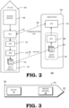
- FIG. 2 illustrates a tracking system 200 in accordance with some embodiments.
- the tracking system 200 includes similar components to those described above with respect to the tracking system 100. However, for the tracking system 100 the TX module 121 is located at the stylus 102 while the Rx module 120 is located at the base device 104. The components perform similarly to the corresponding components of FIG. 1 to support generation of poses for the stylus 102.
- the stylus 102 can be any kind of writing device.
- FIG. 3 illustrates an example embodiment of the stylus 102 that can be employed to write on paper or other media while concurrently generating poses for the stylus 102.
- the stylus 102 includes both the EM coil 107 to support generation of EM poses, and also includes writing material 328.
- the writing material 328 can be any kind of writing material that is dispensed from a tip 323 of the stylus 102 onto a writing surface (e.g. paper or other medium) as a user moves the stylus 102.
- the writing material 328 is ink contained in a reservoir, wherein both the reservoir and the EM coil are placed within a housing that forms the outside of the stylus 102.
- the stylus 102 is a pencil and the writing material 328 is graphite that is contained within a housing of the stylus 102 and is dispensed at the tip 323 of the stylus 102.
- the stylus 102 includes a non-writing nib configured to be placed on a computer or tablet screen or other surface.
- metal or other material situated in close proximity to the Rx module 120 or to the Tx module 121 can cause distortions in the EM field 125, and these distortions can result in inaccuracies in the EM pose data.
- the resulting distortions in the EM field 125 can cause errors in the EM pose data, resulting in pose tracking errors for the stylus 102, and in turn resulting in a poor user experience.
- the distortions in the EM field can be mitigated by placing the EM coil 107 at a distance from the surface that is causing the distortion. For example, in some embodiments, including the example embodiment of FIG.
- the EM coil 107 is placed relatively close to an end 324 of the stylus 102, the end 324 opposite the tip 323.
- the EM coil 107 is therefore relatively far away from the distorting surface when the tip 323 is in contact with that surface, thereby reducing distortions in the EM field 125 and in turn improving the accuracy of the EM pose data.
- the stylus 102 and base device 104 are configured similarly to the embodiment of FIG. 2 .
- the stylus 102 employs an EM coil 430 that is wound around an axis 433 along the length of the stylus 102, which allows the EM coil 430 to be placed within the housing of the stylus 102 with relatively small impact on the form factor of the stylus 102.
- the EM coil 430 is the only coil employed by the Rx module. In other embodiments, the Rx module employs EM coils in addition to the EM coil 430.
- the coil 132 can be implemented with a relatively high number of turns.
- the strength of the EM field 125 is proportional to the number of turns in the coil, such that a long coil wound around the stylus 102 allows for higher signal-to-noise ratio in the EM data while having a relatively small impact on the size of the stylus 102.
- the tracking system can reduce the overall cost of the system by employing existing EM components of a computer, smartphone or other device.
- FIG. 5 An example is illustrated at FIG. 5 .
- the stylus 102 is configured similarly to the embodiment of FIG. 2 , including the EM Tx module 120 and the second sensor 106.
- the base device is a smartphone 540 including a CPU 541 and a magnetometer 542.
- the magnetometer 542 is a 3-axis magnetometer embedded in the smartphone 540 and used for different smartphone operations, such as providing compass-like capabilities.
- the CPU 541 is configured to control the magnetometer 542 to operate in similar fashion to the EM coil 107 of FIGs.
- the CPU 541 can act as the "base” and collect EM pose data from the magnetometer 542, which can then be converted to EM poses by the CPU 541.
- the magnetometer 542 has a relatively low sample rate (e.g. in the 50-200Hz range) which does not readily allow for frequency multiplexing of the EM fields, and accordingly the stylus 102 can employ a pulsed EM configuration which is better suited for these magnetometers.
- EM fields can be multiplexed over different frequencies for simultaneous transmission.
- FIG. 6 illustrates a stylus 602 including a CPU 610 and an EM module 620.
- the EM module 620 can be a Rx EM module similar to the Rx EM module 120 of FIG. 1 , or a Tx EM module similar to the Tx EM module 121 of FIG. 2 .
- the stylus 602 can be employed instead of the stylus 102 in any of the embodiments described with respect to FIGs. 1-5 above.
- the stylus 602 employs a force sensitive tip configuration, composed of a tip 650, a spring 651, and a force sensor 652, which can be a mechanical force sensor or an electrical force sensor.
- the spring 651 is omitted.
- the force sensor 652 indicates the sensed force to the CPU 610 via a binary signal to indicate whether the force at the tip 650 has crossed a specified or programmable threshold.
- the force sensor 652 indicates the level of the sensed force to the CPU 610 via an electrical (digital or analog) signal, thereby indicating variable levels of pressure at the tip 650.
- the CPU 610 can take one or more specified actions, such as executing an application, changing an application parameter (such as the thickness, shade, color, or other aspect of a displayed or stored line), and the like.
- the stylus can employ a tip that is used to assist in pose identification for the stylus.
- FIG. 7 illustrates a stylus 702 including a CPU 710 and an EM module 720.
- the EM module 720 can be a Rx EM module similar to the Rx EM module 120 of FIG. 1 , or a Tx EM module similar to the Tx EM module 121 of FIG. 2 .
- the stylus 702 can be employed instead of the stylus 102 in any of the embodiments described with respect to FIGs. 1-5 above.
- the stylus 702 has a tip configuration that acts as a 2-D sensor when dragged against an arbitrary flat surface, simulating a pen.
- the configuration includes a ball tip 753 and rollers and rotation sensor pairs 756 and 757.
- the roller and rotation sensor pairs 756 and 757 sense the rotation of the ball tip and based on the rotation provide 2-D pose information to the CPU 710.
- the roller and rotation sensor pair 756 indicates the position of the tip 753 along a "y" axis and the roller and rotation sensor pair 757 indicate the position of the tip 753 along a corresponding "x" axis.
- the 2-D pose information can be used to check or augment the pose identified based on the EM pose data as described above.
- FIG. 8 illustrates a stylus 802 including a CPU 810 and an EM module 820.
- the EM module 820 can be an Rx EM module similar to the Rx EM module 120 of FIG. 1 , or a Tx EM module similar to the Tx EM module 121 of FIG. 2 .
- the stylus 802 can be employed instead of the stylus 102 in any of the embodiments described with respect to FIGs. 1-5 above.
- the stylus 802 includes a light source 859 and a photo sensor 858.
- the light source 859 is configured to emit a light beam 861 via a tip of the stylus 802.
- the light beam 861 is reflected off a surface 860 external to the stylus 802, such as writing surface, computer screen, and the like.
- the photosensor 858 uses the reflected light beam to capture images of the surface 860 and provides the images to the CPU 810.
- the CPU 810 compares each captured image to previous captured images to determine a direction of movement of the stylus across the surface 860.
- the CPU 810 can employ the identified direction of movement to augment or check the pose identified based on the EM pose data.
- any of the stylus embodiments described above, including the styli 102, 602, 702, and 802, can include additional components to provide additional inputs or other information to a computer device.
- the stylus can include one or more buttons to indicate additional input data to the computer device.
- the one or more buttons can be placed in convenient location for the user such as, if the stylus is held like a pen or pencil, one of the buttons is placed at or near the user's index finger while another button is placed at or near the user's thumb.
- a button can be placed at an end of the stylus opposite the tip, in a similar location as the button for a retractable ball point pen.
- the stylus can incorporate, in some embodiments, a slider, 1-D trackpad, roller, or similar component (or a combination thereof) that allows for 1-dimensional linear input.
- the 1-D linear input component is placed near the front of the stylus in the location where, when held as a pen, the index finger would normally be placed.
- the component is placed closer to the middle for easy access when the stylus is held as a wand.
- the stylus can include a 2-D trackpad, joystick, or similar component that allows for 2-D analog input into the stylus.
- the 2-D analog input component is placed closer to the middle for easy access with the thumb when the stylus is held as a wand.
- FIG. 9 illustrates a stylus 902, which in different embodiments corresponds to any of the styli 102, 602, 702, and 802 described above, or a combination thereof.
- FIG. 9 also illustrates a dongle 965 including an EM module 966.
- the EM module 966 can be an Rx EM module similar to the Tx EM module 121 of FIG. 1 , or an Rx EM module similar to the Tx EM module 121 of FIG. 2 .
- the stylus 902 includes an EM module 967 that is complementary to the EM module 966.
- the EM module 966 is a Tx module then the EM module 967 is an Rx module and vice versa.
- the dongle 965 can therefore be mated with the connector 968 so that it is easy and convenient for the user to carry the dongle 965 with the stylus 902.
- the stylus 902 provides power from a battery (not shown) or other power source to the dongle 965 via the connector 968 to charge a battery (not shown) that provides power to the EM module 966.
- the dongle 966 can be plugged into a USB port of a computer device, such as smartphone 940 at USB port 941. While plugged into the USB port 941 the EM module 966 is active, either transmitting or receiving the EM field 125, allowing the smartphone 940 to identify poses based on EM pose data as described above with respect to FIG. 1 .
- the dongle 966 itself includes a processor to identify pose data, reducing processing load at the smartphone 940. It will be appreciated that other configurations and form factors for the dongle 960 are possible. For example, in some embodiments the dongle 960 has a "cap" form factor that can fit over the tip of the stylus 902.
- the EM pose data can be used to assist in handwriting or other text or drawing identification (referred to collectively herein as "handwriting capture").
- handwriting that is captured via the EM pose data is converted (e.g. by one or both of the processors 110 and 115, or by another processor) from handwriting to typed text through use of handwriting recognition software or optical character recognition (OCR) software.
- OCR optical character recognition
- the handwritten capture is converted to geometric shapes through the use of shape recognition software.
- Such processing can “clean up” hand-drawn diagrams or generate readable variants of charts and graphs.
- the handwritten capture is converted to mathematical equations. Such processing can "clean up” math equations into presentable digital representations.
- EM pose data allows for handwriting capture on a variety of surfaces, in contrast to conventional handwriting capture that requires use of a specialized surface.
- using EM pose data supports handwriting capture when the relative angle or orientation of the surface is unknown. For example, the user could write on a wall (where the surface is vertical) and also write on a desk (where the surface is horizontal) and the angle of the writing plane is not known a-priori.
- the handwriting capture from stylus 102 is "fit" onto a plane to produce an accurate representation of the handwriting. For example, if the writing surface were angled at 45 degrees but the trajectories are projected onto a plane that is flat (angled at zero degrees), the resulting handwriting would look distorted.
- the plane of the writing surface is determined by a processor, such as the processor 110 or the processor 115.
- the processor employs a plane-fitting algorithm to "fit" the writing trajectories to determine the plane angle.
- the writing plane is determined "on the fly” based on what the user is writing.
- the plane fitting is done with post-processing at the processor.
- the processor determines the angle of writing is based on the direction of the writing.
- FIG. 10 illustrates handwriting 1070 that has been written on a surface with the stylus 102.
- the processor 115 (or other processor) employs a heuristic to determine an angle 1073 relative to a vector 1072 that represents "horizontal" writing (e.g., left to right or right to left).
- the processor 115 uses the angle 1073 to correct the orientation of the handwriting prior to handwriting recognition.
- the processor 115 fits a line 1071 through the handwriting and measures the angle 1073 between the fitted line and the desired angle.
- the orientation of the handwriting can be determined by a machine learning model, such as a neural network.
- the processor performs orientation fitting. For example, handwriting recognition software that can recognize handwriting can incur errors if the handwriting were rotated 180 degrees so that the handwriting is upside-down. Thus, before attempting to recognize the handwriting, the processor 115 determines the "correct side up" orientation of the writing. In some embodiments, the processor attempts to rotate the handwriting by some amount, and then uses a heuristic to score the desirability of the resulting rotation. The processor repeats the process until the score crosses a threshold. An example is illustrated at FIG. 11 in accordance with some embodiments. At block 1102, the processor 115 gives the handwriting an initial orientation and an initial score based on the initial orientation.
- the score can vary in a range of 0.0 to 1.0 and represents a confidence level that the handwriting is in a horizontal orientation.
- the processor 115 determines if the score exceeds a threshold.
- the threshold can be a value of 0.9, indicating a threshold confidence level that the orientation of the handwriting is such that the handwriting can be interpreted by a specified handwriting recognition algorithm. If the score does not exceed the threshold, the method moves to block 1106 and the processor 115 rotates the orientation of the handwriting by a specified amount. The method returns to block 1102 and the processor 115 generates a new score based on the adjusted orientation. The processor 115 continues to incrementally adjust the orientation until, at block 1104, the score exceeds the threshold. In response to the score exceeding the threshold, the method flow moves from block 1104 to block 1108, and the processor 115 executes a handwriting recognition algorithm based on the current orientation of the handwriting (the orientation that resulted in the score exceeding the threshold.
- the processor 115 rotates the captured handwriting by multiple angles, and each rotation is processed in parallel to speed up the processing.
- the scoring is performed by attempting handwriting recognition of some of the handwriting and using the level of confidence from the handwriting recognition algorithm as an input into the score.
- a machine learning model is employed to estimate the angle of rotation necessary for handwriting recognition software to properly process the handwriting strokes.
- Embodiments of the present disclosure include fusing of multiple data sources to improve the tracking quality of the pen device.
- the poses from the EM position tracking subsystem are combined with poses from an IMU to reduce noise and improve angular accuracy.
- a Kalman filter is used to combine data derived from an IMU with data derived from the EM position tracking system to produce a "fused" pose. Fusion can also be used to correct for temporary distortions caused by nearby metal, for example by “dead reckoning" for short periods of time with the IMU when metallic distortion is detected.
- the computer readable storage medium may be embedded in the computing system (e.g., system RAM or ROM), fixedly attached to the computing system (e.g., a magnetic hard drive), removably attached to the computing system (e.g., an optical disc or Universal Serial Bus (USB)-based Flash memory), or coupled to the computer system via a wired or wireless network (e.g., network accessible storage (NAS)).
- system RAM or ROM system RAM or ROM
- USB Universal Serial Bus
- NAS network accessible storage
Landscapes
- Engineering & Computer Science (AREA)
- Theoretical Computer Science (AREA)
- General Engineering & Computer Science (AREA)
- Physics & Mathematics (AREA)
- General Physics & Mathematics (AREA)
- Human Computer Interaction (AREA)
- Computer Vision & Pattern Recognition (AREA)
- Multimedia (AREA)
- Position Input By Displaying (AREA)
Description
- The present disclosure relates generally to input devices for computing platforms, and more particularly to input devices having a stylus or pen form factor.
- The form factor of a computer input device can have a substantial impact on the user experience with a computing platform. Accordingly, to enhance the user experience, computer input devices have been developed that have a pen or stylus form factor. These devices allow the user to hold the input device in a comfortable position with which the user is familiar (i.e. a comfortable writing position). Further, devices with a pen/stylus form factor support relatively precise control by the user, thereby improving the user experience with a variety of applications, such as drawing and painting applications, writing applications, and the like. However, conventional input devices with a pen/stylus form factor typically have limited positional tracking in two dimensions, thereby limiting utility of the devices for applications that employ three-dimensional spaces, such as virtual reality (VR) and augmented reality (AR) applications. Further, conventional pen/stylus input devices sometimes require the user to write on a special surface, such as a specially-designed tablet or paper, in order to track position of the input device. These special surfaces limit the portability and flexibility of the input device.
- Document
WO 2017/044051 A1 discloses a system for determining the pose of a pen on a surface using infrared sensors, an ultrasonic sensor as well as acceleration detectors and a magnetometer. - The invention is set out in the independent claims. Preferred embodiments are defined by the dependent claims.
- The present disclosure may be better understood, and its numerous features and advantages made apparent to those skilled in the art by referencing the accompanying drawings. The use of the same reference symbols in different drawings indicates similar or identical items.
-
FIG. 1 is a block diagram of an electromagnetic (EM) pose tracking system for a writing device employed for computer input in accordance with some embodiments. -
FIG. 2 is a block diagram of another example of an EM pose tracking system for a writing device employed for computer input in accordance with some embodiments. -
FIG. 3 is a block diagram illustrating a writing device that can be used in conjunction with the EM pose tracking systems ofFIG. 1 andFIG. 2 in accordance with some embodiments. -
FIG. 4 is a block diagram illustrating an example of an EM pose tracking system with a writing device using a single coil in the writing device in accordance with some embodiments. -
FIG. 5 is a block diagram illustrating an example of employing an EM pose tracking system for a writing device in conjunction with a portable device such as a smartphone in accordance with some embodiments. -
FIG. 6 is a block diagram illustrating a writing device employing a force sensor that can be used in conjunction with the EM position tracking systems ofFIG. 1 andFIG. 2 in accordance with some embodiments. -
FIG. 7 is a block diagram illustrating a writing device employing a rotation sensor that can be used in conjunction with the EM position tracking systems ofFIG. 1 andFIG. 2 in accordance with some embodiments. -
FIG. 8 is a block diagram illustrating a writing device employing a photo sensor that can be used in conjunction with the EM position tracking systems ofFIG. 1 andFIG. 2 in accordance with some embodiments. -
FIG. 9 is a block diagram illustrating a writing device employing pluggable dongle that can be used in conjunction with the EM position tracking systems ofFIG. 1 andFIG. 2 in accordance with some embodiments. -
FIG. 10 is a diagram illustrating an example of employing the EM position tracking system ofFIG. 1 to detect handwriting orientation in accordance with some embodiments. -
FIG. 11 is a flow diagram illustrating a method of employing the EM position tracking system ofFIG. 1 to identify an orientation of handwriting on a surface for handwriting recognition in accordance with some embodiments. -
FIGs. 1-11 illustrate techniques for employing an electromagnetic (EM) pose tracking system with a computer input device having a pen or stylus form factor. In some embodiments, a base station device includes one of the transmitter (Tx) or receiver (Rx) module for the EM pose tracking system while the computer input device includes the other of the TX and receiver modules. The EM pose tracking system employs the Tx and Rx modules to collect EM pose data indicating a relative pose between the Tx and Rx modules. Based on the EM pose data, the EM pose tracking system (or a computer device working with the EM pose tracking system) identifies a pose (position, orientation, or both position and orientation) of the computer input device. In some embodiments, the pose is identified in a six degree of freedom (6DoF) space, thereby supporting user input for applications employing such a space, such as a VR or AR application. Furthermore, the EM pose tracking system supports identification of the pose without requiring line-of-sight between the base station and the input device, and without requiring a special writing surface, thereby enhancing the flexibility of the input device. In addition, the components of the EM pose tracking system, such as an EM coil, can be inserted into the input device without requiring a substantial increase in the size of the input device, allowing the input device to maintain the pen or stylus form factor, and thus enhancing the user experience. - For convenience, the term "writing device" is used herein to refer to a computer input device having a pen or stylus form factor as described further herein. It will be appreciated that in some embodiments the writing device can include a writing material, such as an ink reservoir or graphite, that supports writing on a medium (e.g., paper) independent of pose tracking. In other embodiments, the writing device does not include a writing material, but includes a nub or tip that supports use of the device on a display screen or other surface. Further, it will be appreciated that the writing device can be employed for uses other than handwriting, including drawing, selection and manipulation of objects in a computer application, including CAD, AR, or VR application, or any other use for which a stylus can provide input to a computer.
-
FIG. 1 illustrates atracking system 100 that employs EM poses to identify poses of a writing device, illustrated asstylus 102. In the depicted example, thetracking system 100 includes abase device 104 and thestylus 102. Thebase device 104 can be part of or connected to a computer device, a base station independent of a computer device, or can be a mobile device in some embodiments. As described further herein, thetracking system 100 is generally configured to identify poses of thestylus 102 based on a weighted combination of EM poses (poses generated based on anEM field 125 as described further herein) and secondary poses (poses generated based on data provided by a secondary sensor 106). Thetracking system 100 can therefore be incorporated into a variety of devices and systems that employ pose identification features. For example, in some embodiments thetracking system 100 is incorporated in a virtual reality (VR) system to identify the pose of thestylus 102 to allow a user to employ thestylus 102 to manipulate objects in a VR environment. Thus, in some configurations, thebase device 104 is a head mounted display (HMD) that displays the VR environment to the user. In other configurations, thebase device 104 is a device separate from the HMD (such as an accessory or a base-station). It will be appreciated that other configurations of thetracking system 100 can be employed. For example, in some embodiments thetracking system 100 does not employ asecondary sensor 106 and generates poses for thestylus 102 based only on EM pose data. - To generate an EM pose, the
tracking system 100 generates theEM field 125, measures a magnitude and/or phase of the generated EM field 125 (referred to herein generally as "EM data"), and computes a relative pose based on the corresponding EM data. In the illustrated embodiment, theEM field 125 is generated by thebase device 104 and the EM data is read at thestylus 102. It will be appreciated that other configurations are possible, including theEM field 125 being generated by thestylus 102 and the EM data being read at thebase device 104, as illustrated below atFIG. 2 . To support generation of the EM field, thebase device 102 includes aTx module 121, whereby theTx module 121 includes atransmitter coil 116 and anamplifier 114. In some embodiments, thetransmitter coil 116 is a tri-axis coil generally configured to generate theEM field 125 at a strength, referred to herein as the transmit power, wherein the transmit power is based on electrical power provided by theamplifier 114 to thetransmitter coil 116. Theamplifier 114 is a programmable amplifier generally configured to generate the electrical power at a magnitude based on received control signaling. Thus, the transmit power for theEM field 114 is a programmable value that is controlled at thebase device 102. The Tx module further includes a digital-to-analog DAC converter 112 that converts values provided by aCPU 115 of thebase device 104 to supply the input to theamplifier 114. In other embodiments, theamplifier 114 is a non-programmable amplifier, and magnitudes of the EM field can be changed simply by reducing the amplitude of the source signal, which could be done digitally or via the DAC. TheCPU 115 can perform other operations on behalf of thebase device 104 and thetracking system 100, including generation of poses for thestylus 102 as described further herein. In other embodiments one or more of these operations can be performed by theCPU 110 or by a third CPU. - To support reading of EM data, the
stylus 102 includes anRx module 120 having areceiver coil 107 and an analog-to-digital converter (ADC) 108. In some embodiments, thereceiver coil 107 is a tri-axis coil configured to generate an analog electrical signal having a magnitude and/or phase indicative of a detectedEM field 125. In some embodiments, such as described further below with respect toFIG. 4 , thereceiver coil 107 may have fewer than three coils. The ADC 108 is generally configured to receive the generated analog signal and convert the analog signal to a digital value indicative of the analog signal, and therefore indicative of the detectedEM field 125. Thus, in the example ofFIG. 1 , the digital values generated by theADC 108 are EM data that can be used for pose identification as described further below. - To support generation of poses, the
stylus 102 includes asecondary sensor 106 configured to generate non-EM pose information for thestylus 102. In some embodiments the secondary sensor is an inertial measurement unit (IMU). In other embodiments, the secondary sensor is part of a secondary tracking system (not illustrated atFIG. 1 ) that generates secondary pose information based on a secondary tracking signal, such as a light-based signal (e.g., a laser, LED light, and the like), a sonic signal (e.g., an ultrasonic signal), and a radio frequency (RF) signal - To support pose identification (that is, identification of poses of either the
base device 102 or the mobile device 104) thestylus 102 and thebase device 104 includeprocessors processors processors base device 102 or themobile device 104 based on a weighted combination of the EM data provided by theADC 108 and the secondary pose data generated by thesecondary sensor 106. In other embodiments, a different processor on an external system (such as a PC computer, for example) is used to compute pose. In one example, in some embodiments, theprocessor 110 identifies the pose based on the following formula:
- In addition, in the example of
FIG. 1 theprocessors communication link 128 to support communication of EM data, secondary pose data, identified poses, or other information. For example, in some embodiments theprocessor 110 identifies poses based on the EM data and secondary pose data and communicates the identified poses to theprocessor 115. In other embodiments, theprocessor 110 communicates the EM data and the secondary pose data to theprocessor 115, which identifies poses based on the weighted combination. Thecommunication link 128 can be a wired communication link, a wireless communication link (e.g. Bluetooth), and the like, or a combination thereof. In other embodiments, the EM data and the secondary pose data can be sent to a third processor (not pictured) where the pose is computed from the weighted combination of the EM data and the secondary pose data. - In some embodiments, one or more of the
processors 110 and 115 (or a third processor not shown atFIG. 1 ) execute additional sets of instructions to use the poses determined based on the EM data and the secondary pose data. For example, in some embodiments theprocessor 115 can execute sets of instructions to display a virtual reality environment to a user and employ the identified poses to determine a location of thestylus 102 in the virtual reality environment, thereby allowing the user to interact with the virtual reality environment using thestylus 102. - In some embodiments, the
stylus 102 is used for capturing handwriting or a hand drawing. The user can write or draw (e.g. with an ink or pencil tip) on paper and the writing or drawing is captured by a computing device based on poses of thestylus 102, allowing the writing or drawing to be displayed at the computing device. In other embodiments, thestylus 102 is used as a stylus on a computer screen in typical stylus use cases. In these embodiments, the stylus could be used to annotate, write, or as regular mouse input. In still other embodiments, thestylus 102 is used as a 3D mouse to manipulate 3D virtual objects. For example, thestylus 102 can be used instead of a "space mouse" to manipulate rotation or displacement of 3D CAD drawings. - As noted above, in some embodiments the Tx and Rx modules of the
tracking system 100 are in reverse positions relative toFIG. 1 . An example is illustrated atFIG. 2 , which illustrates atracking system 200 in accordance with some embodiments. Thetracking system 200 includes similar components to those described above with respect to thetracking system 100. However, for thetracking system 100 theTX module 121 is located at thestylus 102 while theRx module 120 is located at thebase device 104. The components perform similarly to the corresponding components ofFIG. 1 to support generation of poses for thestylus 102. - It will be appreciated that the
stylus 102 can be any kind of writing device.FIG. 3 illustrates an example embodiment of thestylus 102 that can be employed to write on paper or other media while concurrently generating poses for thestylus 102. In the depicted example, thestylus 102 includes both theEM coil 107 to support generation of EM poses, and also includes writingmaterial 328. The writingmaterial 328 can be any kind of writing material that is dispensed from atip 323 of thestylus 102 onto a writing surface (e.g. paper or other medium) as a user moves thestylus 102. Thus, in some embodiments the writingmaterial 328 is ink contained in a reservoir, wherein both the reservoir and the EM coil are placed within a housing that forms the outside of thestylus 102. In other embodiments, thestylus 102 is a pencil and the writingmaterial 328 is graphite that is contained within a housing of thestylus 102 and is dispensed at thetip 323 of thestylus 102. In other embodiments, thestylus 102 includes a non-writing nib configured to be placed on a computer or tablet screen or other surface. - In some cases, metal or other material situated in close proximity to the
Rx module 120 or to theTx module 121 can cause distortions in theEM field 125, and these distortions can result in inaccuracies in the EM pose data. For example, if thestylus 102 is being used to write on a table containing metal, such that thetip 323 is close to the metal, the resulting distortions in theEM field 125 can cause errors in the EM pose data, resulting in pose tracking errors for thestylus 102, and in turn resulting in a poor user experience. However, the distortions in the EM field can be mitigated by placing theEM coil 107 at a distance from the surface that is causing the distortion. For example, in some embodiments, including the example embodiment ofFIG. 3 , theEM coil 107 is placed relatively close to anend 324 of thestylus 102, theend 324 opposite thetip 323. TheEM coil 107 is therefore relatively far away from the distorting surface when thetip 323 is in contact with that surface, thereby reducing distortions in theEM field 125 and in turn improving the accuracy of the EM pose data. - In some cases, it may be desirable to reduce the cost or size of the circuitry in the
stylus 102. An example is illustrated atFIG. 4 in accordance with some embodiments. In the depicted embodiment, thestylus 102 andbase device 104 are configured similarly to the embodiment ofFIG. 2 . However, thestylus 102 employs anEM coil 430 that is wound around anaxis 433 along the length of thestylus 102, which allows theEM coil 430 to be placed within the housing of thestylus 102 with relatively small impact on the form factor of thestylus 102. In some embodiments, theEM coil 430 is the only coil employed by the Rx module. In other embodiments, the Rx module employs EM coils in addition to theEM coil 430. In addition, by winding thecoil 432 along the length of thestylus 102, the coil 132 can be implemented with a relatively high number of turns. As is understood in the art, the strength of theEM field 125 is proportional to the number of turns in the coil, such that a long coil wound around thestylus 102 allows for higher signal-to-noise ratio in the EM data while having a relatively small impact on the size of thestylus 102. - In some embodiments, the tracking system can reduce the overall cost of the system by employing existing EM components of a computer, smartphone or other device. An example is illustrated at
FIG. 5 . In the depicted example, thestylus 102 is configured similarly to the embodiment ofFIG. 2 , including theEM Tx module 120 and thesecond sensor 106. However, in the illustrated example, the base device is asmartphone 540 including aCPU 541 and amagnetometer 542. In some embodiments, themagnetometer 542 is a 3-axis magnetometer embedded in thesmartphone 540 and used for different smartphone operations, such as providing compass-like capabilities. TheCPU 541 is configured to control themagnetometer 542 to operate in similar fashion to theEM coil 107 ofFIGs. 1-2 , and in particular to collect EM pose data from readings of theEM field 125. That is, by using themagnetometer 542 as the base coil for reading EM signals transmitted by thestylus 102, theCPU 541 can act as the "base" and collect EM pose data from themagnetometer 542, which can then be converted to EM poses by theCPU 541. - In some embodiments, the
magnetometer 542 has a relatively low sample rate (e.g. in the 50-200Hz range) which does not readily allow for frequency multiplexing of the EM fields, and accordingly thestylus 102 can employ a pulsed EM configuration which is better suited for these magnetometers. For smartphones with magnetometers or other magnetic sensor with higher sampling rates, EM fields can be multiplexed over different frequencies for simultaneous transmission. - It will be appreciated that the
stylus 102, instead of or in addition to supporting the deposition of writing material on a surface, can employ different configurations of the stylus tip. The different tips can support improved pose detection, additional stylus functionality, or a combination thereof. Examples of different stylus tip configurations are illustrated atFIGs 6-8 in accordance with some embodiments.FIG. 6 illustrates astylus 602 including aCPU 610 and anEM module 620. TheEM module 620 can be a Rx EM module similar to theRx EM module 120 ofFIG. 1 , or a Tx EM module similar to theTx EM module 121 ofFIG. 2 . Accordingly, thestylus 602 can be employed instead of thestylus 102 in any of the embodiments described with respect toFIGs. 1-5 above. - The
stylus 602 employs a force sensitive tip configuration, composed of atip 650, aspring 651, and aforce sensor 652, which can be a mechanical force sensor or an electrical force sensor. In some embodiments, thespring 651 is omitted. When thetip 650 contacts a surface (e.g. when a user places thetip 650 on a screen or other writing surface), the force of the surface against the tip translates down the tip applying a force that is sensed by theforce sensor 652, which indicates the sensed force to theCPU 610. In some embodiments, theforce sensor 652 indicates the sensed force to theCPU 610 via a binary signal to indicate whether the force at thetip 650 has crossed a specified or programmable threshold. In other embodiments, theforce sensor 652 indicates the level of the sensed force to theCPU 610 via an electrical (digital or analog) signal, thereby indicating variable levels of pressure at thetip 650. Based on the information provided by theforce sensor 652, theCPU 610 can take one or more specified actions, such as executing an application, changing an application parameter (such as the thickness, shade, color, or other aspect of a displayed or stored line), and the like. - In some embodiments, such as the example of
FIG. 7 , the stylus can employ a tip that is used to assist in pose identification for the stylus.FIG. 7 illustrates astylus 702 including aCPU 710 and anEM module 720. As withFIG. 6 , theEM module 720 can be a Rx EM module similar to theRx EM module 120 ofFIG. 1 , or a Tx EM module similar to theTx EM module 121 ofFIG. 2 . Further, thestylus 702 can be employed instead of thestylus 102 in any of the embodiments described with respect toFIGs. 1-5 above. Thestylus 702 has a tip configuration that acts as a 2-D sensor when dragged against an arbitrary flat surface, simulating a pen. The configuration includes aball tip 753 and rollers and rotation sensor pairs 756 and 757. As the user moves the stylus over the surface, theball tip 753 rotates. The roller and rotation sensor pairs 756 and 757 sense the rotation of the ball tip and based on the rotation provide 2-D pose information to theCPU 710. For example, in some embodiments the roller androtation sensor pair 756 indicates the position of thetip 753 along a "y" axis and the roller androtation sensor pair 757 indicate the position of thetip 753 along a corresponding "x" axis. The 2-D pose information can be used to check or augment the pose identified based on the EM pose data as described above. - In some embodiments, such as the example of
FIG. 8 , instead of tracking the 2-D position of the tip via a mechanical configuration, the stylus can employ optical sensing.FIG. 8 illustrates astylus 802 including aCPU 810 and anEM module 820. As withFIG. 6 , theEM module 820 can be an Rx EM module similar to theRx EM module 120 ofFIG. 1 , or a Tx EM module similar to theTx EM module 121 ofFIG. 2 . Further, thestylus 802 can be employed instead of thestylus 102 in any of the embodiments described with respect toFIGs. 1-5 above. Thestylus 802 includes alight source 859 and aphoto sensor 858. Thelight source 859 is configured to emit alight beam 861 via a tip of thestylus 802. Thelight beam 861 is reflected off asurface 860 external to thestylus 802, such as writing surface, computer screen, and the like. The photosensor 858 uses the reflected light beam to capture images of thesurface 860 and provides the images to theCPU 810. TheCPU 810 compares each captured image to previous captured images to determine a direction of movement of the stylus across thesurface 860. TheCPU 810 can employ the identified direction of movement to augment or check the pose identified based on the EM pose data. - It will be appreciated that any of the stylus embodiments described above, including the
styli - In some embodiments, the flexibility and portability of the stylus can be enhanced by allowing the
base device 104 to be removably integrated with the stylus. An example is illustrated atFIG. 9 in accordance with some embodiments.FIG. 9 illustrates astylus 902, which in different embodiments corresponds to any of thestyli FIG. 9 also illustrates adongle 965 including anEM module 966. TheEM module 966 can be an Rx EM module similar to theTx EM module 121 ofFIG. 1 , or an Rx EM module similar to theTx EM module 121 ofFIG. 2 . Thestylus 902 includes anEM module 967 that is complementary to theEM module 966. Thus, if theEM module 966 is a Tx module then theEM module 967 is an Rx module and vice versa. Thedongle 965 can therefore be mated with theconnector 968 so that it is easy and convenient for the user to carry thedongle 965 with thestylus 902. In some embodiments, thestylus 902 provides power from a battery (not shown) or other power source to thedongle 965 via theconnector 968 to charge a battery (not shown) that provides power to theEM module 966. - The
dongle 966 can be plugged into a USB port of a computer device, such assmartphone 940 atUSB port 941. While plugged into theUSB port 941 theEM module 966 is active, either transmitting or receiving theEM field 125, allowing thesmartphone 940 to identify poses based on EM pose data as described above with respect toFIG. 1 . In some embodiments thedongle 966 itself includes a processor to identify pose data, reducing processing load at thesmartphone 940. It will be appreciated that other configurations and form factors for the dongle 960 are possible. For example, in some embodiments the dongle 960 has a "cap" form factor that can fit over the tip of thestylus 902. - In some embodiments, the EM pose data can be used to assist in handwriting or other text or drawing identification (referred to collectively herein as "handwriting capture"). For example, in one embodiment, handwriting that is captured via the EM pose data is converted (e.g. by one or both of the
processors - Using EM pose data allows for handwriting capture on a variety of surfaces, in contrast to conventional handwriting capture that requires use of a specialized surface. In particular, using EM pose data supports handwriting capture when the relative angle or orientation of the surface is unknown. For example, the user could write on a wall (where the surface is vertical) and also write on a desk (where the surface is horizontal) and the angle of the writing plane is not known a-priori.
- To support handwriting capture on an unknown surface, in some embodiments the handwriting capture from
stylus 102 is "fit" onto a plane to produce an accurate representation of the handwriting. For example, if the writing surface were angled at 45 degrees but the trajectories are projected onto a plane that is flat (angled at zero degrees), the resulting handwriting would look distorted. In order to preserve an accurate representation of what was handwritten, the plane of the writing surface is determined by a processor, such as theprocessor 110 or theprocessor 115. In one embodiment, the processor employs a plane-fitting algorithm to "fit" the writing trajectories to determine the plane angle. In other embodiments, the writing plane is determined "on the fly" based on what the user is writing. In other embodiments, the plane fitting is done with post-processing at the processor. - In some embodiments, the processor determines the angle of writing is based on the direction of the writing. An example is illustrated at
FIG. 10 , which illustrateshandwriting 1070 that has been written on a surface with thestylus 102. The processor 115 (or other processor) employs a heuristic to determine anangle 1073 relative to avector 1072 that represents "horizontal" writing (e.g., left to right or right to left). Theprocessor 115 uses theangle 1073 to correct the orientation of the handwriting prior to handwriting recognition. For example, in some embodiments theprocessor 115 fits aline 1071 through the handwriting and measures theangle 1073 between the fitted line and the desired angle. In other embodiments the orientation of the handwriting can be determined by a machine learning model, such as a neural network. - In some embodiments, the processor performs orientation fitting. For example, handwriting recognition software that can recognize handwriting can incur errors if the handwriting were rotated 180 degrees so that the handwriting is upside-down. Thus, before attempting to recognize the handwriting, the
processor 115 determines the "correct side up" orientation of the writing. In some embodiments, the processor attempts to rotate the handwriting by some amount, and then uses a heuristic to score the desirability of the resulting rotation. The processor repeats the process until the score crosses a threshold. An example is illustrated atFIG. 11 in accordance with some embodiments. Atblock 1102, theprocessor 115 gives the handwriting an initial orientation and an initial score based on the initial orientation. For example, in some embodiments the score can vary in a range of 0.0 to 1.0 and represents a confidence level that the handwriting is in a horizontal orientation. Atblock 1104, theprocessor 115 determines if the score exceeds a threshold. In the above example, the threshold can be a value of 0.9, indicating a threshold confidence level that the orientation of the handwriting is such that the handwriting can be interpreted by a specified handwriting recognition algorithm. If the score does not exceed the threshold, the method moves to block 1106 and theprocessor 115 rotates the orientation of the handwriting by a specified amount. The method returns to block 1102 and theprocessor 115 generates a new score based on the adjusted orientation. Theprocessor 115 continues to incrementally adjust the orientation until, atblock 1104, the score exceeds the threshold. In response to the score exceeding the threshold, the method flow moves fromblock 1104 to block 1108, and theprocessor 115 executes a handwriting recognition algorithm based on the current orientation of the handwriting (the orientation that resulted in the score exceeding the threshold. - In other embodiments, the
processor 115 rotates the captured handwriting by multiple angles, and each rotation is processed in parallel to speed up the processing. In some embodiments, the scoring is performed by attempting handwriting recognition of some of the handwriting and using the level of confidence from the handwriting recognition algorithm as an input into the score. In yet other embodiments, a machine learning model is employed to estimate the angle of rotation necessary for handwriting recognition software to properly process the handwriting strokes. - Embodiments of the present disclosure include fusing of multiple data sources to improve the tracking quality of the pen device. In one embodiment, the poses from the EM position tracking subsystem are combined with poses from an IMU to reduce noise and improve angular accuracy. In some embodiments a Kalman filter is used to combine data derived from an IMU with data derived from the EM position tracking system to produce a "fused" pose. Fusion can also be used to correct for temporary distortions caused by nearby metal, for example by "dead reckoning" for short periods of time with the IMU when metallic distortion is detected.
- In some embodiments, certain aspects of the techniques described above may implemented by one or more processors of a processing system executing software. The software comprises one or more sets of executable instructions stored or otherwise tangibly embodied on a non-transitory computer readable storage medium. The software can include the instructions and certain data that, when executed by the one or more processors, manipulate the one or more processors to perform one or more aspects of the techniques described above. The non-transitory computer readable storage medium can include, for example, a magnetic or optical disk storage device, solid state storage devices such as Flash memory, a cache, random access memory (RAM) or other non-volatile memory device or devices, and the like. The executable instructions stored on the non-transitory computer readable storage medium may be in source code, assembly language code, object code, or other instruction format that is interpreted or otherwise executable by one or more processors.
- A computer readable storage medium may include any storage medium, or combination of storage media, accessible by a computer system during use to provide instructions and/or data to the computer system. Such storage media can include, but is not limited to, optical media (e.g., compact disc (CD), digital versatile disc (DVD), Blu-Ray disc), magnetic media (e.g., floppy disc, magnetic tape, or magnetic hard drive), volatile memory (e.g., random access memory (RAM) or cache), non-volatile memory (e.g., read-only memory (ROM) or Flash memory), or microelectromechanical systems (MEMS)-based storage media. The computer readable storage medium may be embedded in the computing system (e.g., system RAM or ROM), fixedly attached to the computing system (e.g., a magnetic hard drive), removably attached to the computing system (e.g., an optical disc or Universal Serial Bus (USB)-based Flash memory), or coupled to the computer system via a wired or wireless network (e.g., network accessible storage (NAS)).
- Note that not all of the activities or elements described above in the general description are required, that a portion of a specific activity or device may not be required, and that one or more further activities may be performed, or elements included, in addition to those described. Still further, the order in which activities are listed are not necessarily the order in which they are performed. Also, the concepts have been described with reference to specific embodiments. However, one of ordinary skill in the art appreciates that various modifications and changes can be made without departing from the scope of the present disclosure as set forth in the claims below. Accordingly, the specification and figures are to be regarded in an illustrative rather than a restrictive sense, and all such modifications are intended to be included within the scope of the present disclosure.
- Benefits, other advantages, and solutions to problems have been described above with regard to specific embodiments. However, the benefits, advantages, solutions to problems, and any feature(s) that may cause any benefit, advantage, or solution to occur or become more pronounced are not to be construed as a critical, required, or essential feature of any or all the claims. Moreover, the particular embodiments disclosed above are illustrative only, as the disclosed subject matter may be modified and practiced in different but equivalent manners apparent to those skilled in the art having the benefit of the teachings herein. No limitations are intended to the details of construction or design herein shown, other than as described in the claims below. It is therefore evident that the particular embodiments disclosed above may be altered or modified and all such variations are considered within the scope of the disclosed subject matter. Accordingly, the protection sought herein is as set forth in the claims below.
Claims (14)
- A writing device comprising:an electromagnetic, EM, tracking module (120, 121, 620, 720, 820, 967) to measure a magnitude and/or phase of a generated EM field (125) and to generate, using measured magnitude and/or phase field values, EM pose data indicative of a relative pose between an EM transmitter (116) and an EM receiver (107, 430);a processor (110) to process the EM pose data for identification of a pose of the writing device (102, 602, 702, 802, 902) based on the relative pose;a sensor (106) to generate a first sensor pose of the writing device based on sensor data;characterized in thatthe processor is configured to identify the pose of the writing device based on a weighted combination of the relative pose and the first sensor pose.
- The writing device of claim 1, further comprising:
a receiver coil (107, 430) configured to generate an analog electrical signal having the magnitude and/or phase indicative of the EM field. - The writing device of claim 1 or 2, whereina) the pose is employed to track movements of the writing device at a computer device (540, 940); and/orb) the processor is configured to process the EM pose data for identification of a pose of the writing device based on the relative pose to manipulate objects in a virtual reality, VR, environment.
- The writing device of any one of the preceding claims, wherein the writing device includes a first end (323) and a second end (324) opposite the first end, and wherein a writing implement (328) is located at the first end and the EM tracking module is located at at least 1 cm distance from the first end.
- The writing device of any one of the preceding claims, wherein the sensor is selected from the group consisting of an inertial measurement unit, an ultrasonic sensor, a light sensor, a sonic sensor, and a radio frequency, RF, sensor.
- The writing device of any one of the preceding claims, wherein the EM tracking module comprises fewer than three EM coil axes.
- The writing device of claim 6, wherein the writing device comprises a stylus (102, 602, 702, 802, 902), and wherein an EM receiver coil (430) is wound around a long axis (433) of the stylus.
- The writing device of any one of the preceding claims, further comprising:a sensor (652; 756, 757) to indicate a 2-dimensional position of a tip (650, 753) of the writing device relative to a writing surface;wherein the processor is configured to identify the pose of the writing device based on the position of the tip.
- The writing device of any one of the preceding claims, further comprising
a base device which comprises one of the EM transmitter and EM receiver and which is removably integrated with the writing device. - The writing device of claim 9, the base device further comprising:
a dongle (965) that comprises one of the EM transmitter and EM receiver, wherein, optionally, the dongle is pluggable at an end of the writing device. - A method for identifying a pose of a writing device (102, 602, 702, 802, 902), comprising:receiving EM pose data based on using measured magnitude and/or phase EM field values, the EM pose data being indicative of a relative pose of an EM transmitter (116) in relation to an EM receiver (107, 430), wherein a base station device (104, 540, 940) includes one of the EM, transmitter or EM receiver and the writing device includes the other of the EM transmitter and EM receiver;generating a first sensor pose of the writing device based on sensor data of a sensor (106) of the writing device; and characterized by identifying a pose of the writing device based on a weighted combination of the relative pose and the first sensor pose.
- The method of claim 11, further comprising: capturing handwriting based on the pose of the writing device, optionally, further comprising:a)
determining an orientation of the handwriting by:iteratively rotating the handwriting;for each iteration, determining an orientation score; andselecting an orientation of the handwriting in response to the orientation score exceeding a threshold; and/orb)determining a direction of the handwriting; anddetermining an orientation of the handwriting based on the direction. - A pose tracking system, comprising:a base station device (104, 540, 940) including one of a electromagnetic, EM, transmitter or EM receiver module for the pose tracking system;a computer input device (102, 602, 702, 802, 902) including the other of the EM transmitter and EM receiver modules; anda sensor (106) of the input device to generate a first sensor pose of the input device based on sensor data;wherein the pose tracking system is configured to employ the EM transmitter and EM receiver modules to generate and collect EM pose data using measured magnitude and/or phase EM field values and indicating a relative pose between the EM transmitter and EM receiver module and characterized in that the pose tracking system is further configured to process the EM pose data for identification of a pose of the computer input device based on a weighted combination of the relative pose and the first sensor pose.
- The pose tracking system of claim 13, wherein the computer input device comprises a writing device of any one of claims 1 to 10.
Applications Claiming Priority (2)
| Application Number | Priority Date | Filing Date | Title |
|---|---|---|---|
| US201862743030P | 2018-10-09 | 2018-10-09 | |
| PCT/US2019/055396 WO2020076950A1 (en) | 2018-10-09 | 2019-10-09 | Writing device with electromagnetic tracking |
Publications (2)
| Publication Number | Publication Date |
|---|---|
| EP3864497A1 EP3864497A1 (en) | 2021-08-18 |
| EP3864497B1 true EP3864497B1 (en) | 2025-07-02 |
Family
ID=68345068
Family Applications (1)
| Application Number | Title | Priority Date | Filing Date |
|---|---|---|---|
| EP19794826.8A Active EP3864497B1 (en) | 2018-10-09 | 2019-10-09 | Writing device with electromagnetic tracking |
Country Status (4)
| Country | Link |
|---|---|
| US (1) | US11762485B2 (en) |
| EP (1) | EP3864497B1 (en) |
| CN (1) | CN113039511B (en) |
| WO (1) | WO2020076950A1 (en) |
Family Cites Families (12)
| Publication number | Priority date | Publication date | Assignee | Title |
|---|---|---|---|---|
| JP3958003B2 (en) * | 2000-09-29 | 2007-08-15 | 独立行政法人科学技術振興機構 | Character recognition method, character recognition program, computer-readable recording medium recording character recognition program, and character recognition apparatus |
| ES2272965T3 (en) * | 2002-04-15 | 2007-05-01 | Epos Technologies Limited | METHOD AND SYSTEM FOR OBTAINING POSITION DATA. |
| US7489308B2 (en) * | 2003-02-14 | 2009-02-10 | Microsoft Corporation | Determining the location of the tip of an electronic stylus |
| JP2004272377A (en) | 2003-03-05 | 2004-09-30 | Ricoh Co Ltd | Character editing device, character input / display device, character editing method, character editing program, and storage medium |
| US9229540B2 (en) * | 2004-01-30 | 2016-01-05 | Electronic Scripting Products, Inc. | Deriving input from six degrees of freedom interfaces |
| US9013485B2 (en) * | 2011-06-30 | 2015-04-21 | Adobe Systems Incorporated | Systems and methods for synthesizing high fidelity stroke data for lower dimension input strokes |
| EP2828793A4 (en) * | 2012-03-23 | 2015-07-01 | Microsoft Technology Licensing Llc | RECOGNITION WITHOUT ROTATION OF MANUSCRIPTED CHARACTERS |
| JP6038572B2 (en) * | 2012-09-26 | 2016-12-07 | 株式会社ワコム | Position indicator and electronic ink cartridge |
| CN105408840B (en) * | 2013-06-19 | 2019-11-01 | 诺基亚技术有限公司 | electronic scribble entry |
| JP2018533146A (en) * | 2015-09-07 | 2018-11-08 | チーウチャーンピアット、ソンブーンCHIEWCHARNPIPAT, Somboon | Digital writing instruments |
| US10558260B2 (en) * | 2017-12-15 | 2020-02-11 | Microsoft Technology Licensing, Llc | Detecting the pose of an out-of-range controller |
| US10928946B2 (en) * | 2019-02-15 | 2021-02-23 | Dell Products L.P. | Touchscreen stylus and display module interface |
-
2019
- 2019-10-09 US US17/283,764 patent/US11762485B2/en active Active
- 2019-10-09 CN CN201980066373.XA patent/CN113039511B/en active Active
- 2019-10-09 WO PCT/US2019/055396 patent/WO2020076950A1/en not_active Ceased
- 2019-10-09 EP EP19794826.8A patent/EP3864497B1/en active Active
Also Published As
| Publication number | Publication date |
|---|---|
| CN113039511A (en) | 2021-06-25 |
| WO2020076950A1 (en) | 2020-04-16 |
| EP3864497A1 (en) | 2021-08-18 |
| US11762485B2 (en) | 2023-09-19 |
| US20210333897A1 (en) | 2021-10-28 |
| CN113039511B (en) | 2024-11-08 |
Similar Documents
| Publication | Publication Date | Title |
|---|---|---|
| US11861072B2 (en) | Self-mixing interferometry-based input device | |
| US20090183929A1 (en) | Writing system with camera | |
| CN103353793B (en) | A new type of electronic pen and intelligent terminal | |
| US7508384B2 (en) | Writing system | |
| KR100465241B1 (en) | Motion recognition system using a imaginary writing plane and method thereof | |
| CN102915130B (en) | Moving trajectory correction method and moving trajectory generating method | |
| CN104385808B (en) | Former handwriting record smart pen based on inertia measurement | |
| JP2004227563A (en) | Integration of inertia sensor | |
| KR20040073997A (en) | Determining the location of the tip of an electronic stylus | |
| CN102375567A (en) | Pen-shaped pointing device, displacement information providing method, and displacement information providing system | |
| CN103049115B (en) | Handwriting input device for recording motion gesture of handwriting pen | |
| KR100360477B1 (en) | Wireless electronic pen | |
| Zhang et al. | Towards an ubiquitous wireless digital writing instrument using MEMS motion sensing technology | |
| US11762485B2 (en) | Writing device with electromagnetic tracking | |
| CN204172543U (en) | Based on the former handwriting record smart pen of inertia measurement | |
| CN112462932B (en) | Self-mixing interferometry-based gesture input system for wearable or handheld devices | |
| US9442577B2 (en) | System for inputting graphical elements | |
| KR102261530B1 (en) | Handwriting input device | |
| KR102397236B1 (en) | Method for creating user defined gesture profile based on user's repetitive motions and recognizing gesture | |
| KR20230030472A (en) | Method for creating user defined gesture profile based on user's repetitive motion and recognizing gesture | |
| KR20220131658A (en) | A wearable device that determines a motion signal to control a host device based on machine learning | |
| US12578809B2 (en) | Input device including optical sensor | |
| KR102472784B1 (en) | method of providing hovering for an optical digital pen by use of a gyro sensor | |
| EP2677401B1 (en) | Image data generation using a handheld electronic device | |
| CN120161957A (en) | Active pen and interactive system |
Legal Events
| Date | Code | Title | Description |
|---|---|---|---|
| STAA | Information on the status of an ep patent application or granted ep patent |
Free format text: STATUS: UNKNOWN |
|
| STAA | Information on the status of an ep patent application or granted ep patent |
Free format text: STATUS: THE INTERNATIONAL PUBLICATION HAS BEEN MADE |
|
| PUAI | Public reference made under article 153(3) epc to a published international application that has entered the european phase |
Free format text: ORIGINAL CODE: 0009012 |
|
| STAA | Information on the status of an ep patent application or granted ep patent |
Free format text: STATUS: REQUEST FOR EXAMINATION WAS MADE |
|
| 17P | Request for examination filed |
Effective date: 20210407 |
|
| AK | Designated contracting states |
Kind code of ref document: A1 Designated state(s): AL AT BE BG CH CY CZ DE DK EE ES FI FR GB GR HR HU IE IS IT LI LT LU LV MC MK MT NL NO PL PT RO RS SE SI SK SM TR |
|
| DAV | Request for validation of the european patent (deleted) | ||
| DAX | Request for extension of the european patent (deleted) | ||
| STAA | Information on the status of an ep patent application or granted ep patent |
Free format text: STATUS: EXAMINATION IS IN PROGRESS |
|
| 17Q | First examination report despatched |
Effective date: 20230207 |
|
| GRAP | Despatch of communication of intention to grant a patent |
Free format text: ORIGINAL CODE: EPIDOSNIGR1 |
|
| STAA | Information on the status of an ep patent application or granted ep patent |
Free format text: STATUS: GRANT OF PATENT IS INTENDED |
|
| INTG | Intention to grant announced |
Effective date: 20250130 |
|
| GRAS | Grant fee paid |
Free format text: ORIGINAL CODE: EPIDOSNIGR3 |
|
| GRAA | (expected) grant |
Free format text: ORIGINAL CODE: 0009210 |
|
| STAA | Information on the status of an ep patent application or granted ep patent |
Free format text: STATUS: THE PATENT HAS BEEN GRANTED |
|
| AK | Designated contracting states |
Kind code of ref document: B1 Designated state(s): AL AT BE BG CH CY CZ DE DK EE ES FI FR GB GR HR HU IE IS IT LI LT LU LV MC MK MT NL NO PL PT RO RS SE SI SK SM TR |
|
| P01 | Opt-out of the competence of the unified patent court (upc) registered |
Free format text: CASE NUMBER: APP_24818/2025 Effective date: 20250523 |
|
| REG | Reference to a national code |
Ref country code: GB Ref legal event code: FG4D |
|
| REG | Reference to a national code |
Ref country code: CH Ref legal event code: EP |
|
| REG | Reference to a national code |
Ref country code: DE Ref legal event code: R096 Ref document number: 602019071984 Country of ref document: DE |
|
| REG | Reference to a national code |
Ref country code: IE Ref legal event code: FG4D |
|
| REG | Reference to a national code |
Ref country code: NL Ref legal event code: MP Effective date: 20250702 |
|
| PG25 | Lapsed in a contracting state [announced via postgrant information from national office to epo] |
Ref country code: PT Free format text: LAPSE BECAUSE OF FAILURE TO SUBMIT A TRANSLATION OF THE DESCRIPTION OR TO PAY THE FEE WITHIN THE PRESCRIBED TIME-LIMIT Effective date: 20251103 |
|
| PG25 | Lapsed in a contracting state [announced via postgrant information from national office to epo] |
Ref country code: NL Free format text: LAPSE BECAUSE OF FAILURE TO SUBMIT A TRANSLATION OF THE DESCRIPTION OR TO PAY THE FEE WITHIN THE PRESCRIBED TIME-LIMIT Effective date: 20250702 |
|
| REG | Reference to a national code |
Ref country code: AT Ref legal event code: MK05 Ref document number: 1809976 Country of ref document: AT Kind code of ref document: T Effective date: 20250702 |
|
| PG25 | Lapsed in a contracting state [announced via postgrant information from national office to epo] |
Ref country code: IS Free format text: LAPSE BECAUSE OF FAILURE TO SUBMIT A TRANSLATION OF THE DESCRIPTION OR TO PAY THE FEE WITHIN THE PRESCRIBED TIME-LIMIT Effective date: 20251102 |
|
| PGFP | Annual fee paid to national office [announced via postgrant information from national office to epo] |
Ref country code: DE Payment date: 20251029 Year of fee payment: 7 |
|
| PGFP | Annual fee paid to national office [announced via postgrant information from national office to epo] |
Ref country code: GB Payment date: 20251027 Year of fee payment: 7 |
|
| PG25 | Lapsed in a contracting state [announced via postgrant information from national office to epo] |
Ref country code: NO Free format text: LAPSE BECAUSE OF FAILURE TO SUBMIT A TRANSLATION OF THE DESCRIPTION OR TO PAY THE FEE WITHIN THE PRESCRIBED TIME-LIMIT Effective date: 20251002 |
|
| REG | Reference to a national code |
Ref country code: LT Ref legal event code: MG9D |
|
| PG25 | Lapsed in a contracting state [announced via postgrant information from national office to epo] |
Ref country code: AT Free format text: LAPSE BECAUSE OF FAILURE TO SUBMIT A TRANSLATION OF THE DESCRIPTION OR TO PAY THE FEE WITHIN THE PRESCRIBED TIME-LIMIT Effective date: 20250702 |
|
| PG25 | Lapsed in a contracting state [announced via postgrant information from national office to epo] |
Ref country code: FI Free format text: LAPSE BECAUSE OF FAILURE TO SUBMIT A TRANSLATION OF THE DESCRIPTION OR TO PAY THE FEE WITHIN THE PRESCRIBED TIME-LIMIT Effective date: 20250702 |
|
| PG25 | Lapsed in a contracting state [announced via postgrant information from national office to epo] |
Ref country code: HR Free format text: LAPSE BECAUSE OF FAILURE TO SUBMIT A TRANSLATION OF THE DESCRIPTION OR TO PAY THE FEE WITHIN THE PRESCRIBED TIME-LIMIT Effective date: 20250702 |
|
| PGFP | Annual fee paid to national office [announced via postgrant information from national office to epo] |
Ref country code: FR Payment date: 20251027 Year of fee payment: 7 |
|
| PG25 | Lapsed in a contracting state [announced via postgrant information from national office to epo] |
Ref country code: GR Free format text: LAPSE BECAUSE OF FAILURE TO SUBMIT A TRANSLATION OF THE DESCRIPTION OR TO PAY THE FEE WITHIN THE PRESCRIBED TIME-LIMIT Effective date: 20251003 |
|
| PG25 | Lapsed in a contracting state [announced via postgrant information from national office to epo] |
Ref country code: SE Free format text: LAPSE BECAUSE OF FAILURE TO SUBMIT A TRANSLATION OF THE DESCRIPTION OR TO PAY THE FEE WITHIN THE PRESCRIBED TIME-LIMIT Effective date: 20250702 Ref country code: CZ Free format text: LAPSE BECAUSE OF FAILURE TO SUBMIT A TRANSLATION OF THE DESCRIPTION OR TO PAY THE FEE WITHIN THE PRESCRIBED TIME-LIMIT Effective date: 20250702 |
|
| PG25 | Lapsed in a contracting state [announced via postgrant information from national office to epo] |
Ref country code: LV Free format text: LAPSE BECAUSE OF FAILURE TO SUBMIT A TRANSLATION OF THE DESCRIPTION OR TO PAY THE FEE WITHIN THE PRESCRIBED TIME-LIMIT Effective date: 20250702 |
|
| PG25 | Lapsed in a contracting state [announced via postgrant information from national office to epo] |
Ref country code: BG Free format text: LAPSE BECAUSE OF FAILURE TO SUBMIT A TRANSLATION OF THE DESCRIPTION OR TO PAY THE FEE WITHIN THE PRESCRIBED TIME-LIMIT Effective date: 20250702 Ref country code: PL Free format text: LAPSE BECAUSE OF FAILURE TO SUBMIT A TRANSLATION OF THE DESCRIPTION OR TO PAY THE FEE WITHIN THE PRESCRIBED TIME-LIMIT Effective date: 20250702 |
|
| PG25 | Lapsed in a contracting state [announced via postgrant information from national office to epo] |
Ref country code: RS Free format text: LAPSE BECAUSE OF FAILURE TO SUBMIT A TRANSLATION OF THE DESCRIPTION OR TO PAY THE FEE WITHIN THE PRESCRIBED TIME-LIMIT Effective date: 20251002 |
|
| PG25 | Lapsed in a contracting state [announced via postgrant information from national office to epo] |
Ref country code: ES Free format text: LAPSE BECAUSE OF FAILURE TO SUBMIT A TRANSLATION OF THE DESCRIPTION OR TO PAY THE FEE WITHIN THE PRESCRIBED TIME-LIMIT Effective date: 20250702 |
|
| PG25 | Lapsed in a contracting state [announced via postgrant information from national office to epo] |
Ref country code: RO Free format text: LAPSE BECAUSE OF FAILURE TO SUBMIT A TRANSLATION OF THE DESCRIPTION OR TO PAY THE FEE WITHIN THE PRESCRIBED TIME-LIMIT Effective date: 20250702 |
|
| PG25 | Lapsed in a contracting state [announced via postgrant information from national office to epo] |
Ref country code: SM Free format text: LAPSE BECAUSE OF FAILURE TO SUBMIT A TRANSLATION OF THE DESCRIPTION OR TO PAY THE FEE WITHIN THE PRESCRIBED TIME-LIMIT Effective date: 20250702 |
|
| PG25 | Lapsed in a contracting state [announced via postgrant information from national office to epo] |
Ref country code: DK Free format text: LAPSE BECAUSE OF FAILURE TO SUBMIT A TRANSLATION OF THE DESCRIPTION OR TO PAY THE FEE WITHIN THE PRESCRIBED TIME-LIMIT Effective date: 20250702 |
|
| PG25 | Lapsed in a contracting state [announced via postgrant information from national office to epo] |
Ref country code: IT Free format text: LAPSE BECAUSE OF FAILURE TO SUBMIT A TRANSLATION OF THE DESCRIPTION OR TO PAY THE FEE WITHIN THE PRESCRIBED TIME-LIMIT Effective date: 20250702 |
|
| PG25 | Lapsed in a contracting state [announced via postgrant information from national office to epo] |
Ref country code: EE Free format text: LAPSE BECAUSE OF FAILURE TO SUBMIT A TRANSLATION OF THE DESCRIPTION OR TO PAY THE FEE WITHIN THE PRESCRIBED TIME-LIMIT Effective date: 20250702 Ref country code: SK Free format text: LAPSE BECAUSE OF FAILURE TO SUBMIT A TRANSLATION OF THE DESCRIPTION OR TO PAY THE FEE WITHIN THE PRESCRIBED TIME-LIMIT Effective date: 20250702 |
|
| PLBE | No opposition filed within time limit |
Free format text: ORIGINAL CODE: 0009261 |
|
| STAA | Information on the status of an ep patent application or granted ep patent |
Free format text: STATUS: NO OPPOSITION FILED WITHIN TIME LIMIT |