EP3864213B1 - Multiple use detergent dispenser - Google Patents
Multiple use detergent dispenser Download PDFInfo
- Publication number
- EP3864213B1 EP3864213B1 EP19897392.7A EP19897392A EP3864213B1 EP 3864213 B1 EP3864213 B1 EP 3864213B1 EP 19897392 A EP19897392 A EP 19897392A EP 3864213 B1 EP3864213 B1 EP 3864213B1
- Authority
- EP
- European Patent Office
- Prior art keywords
- detergent
- door
- unit
- carrier
- dispenser
- Prior art date
- Legal status (The legal status is an assumption and is not a legal conclusion. Google has not performed a legal analysis and makes no representation as to the accuracy of the status listed.)
- Active
Links
Images




Classifications
-
- A—HUMAN NECESSITIES
- A47—FURNITURE; DOMESTIC ARTICLES OR APPLIANCES; COFFEE MILLS; SPICE MILLS; SUCTION CLEANERS IN GENERAL
- A47L—DOMESTIC WASHING OR CLEANING; SUCTION CLEANERS IN GENERAL
- A47L15/00—Washing or rinsing machines for crockery or tableware
- A47L15/42—Details
- A47L15/44—Devices for adding cleaning agents; Devices for dispensing cleaning agents, rinsing aids or deodorants
- A47L15/4463—Multi-dose dispensing arrangements
-
- A—HUMAN NECESSITIES
- A47—FURNITURE; DOMESTIC ARTICLES OR APPLIANCES; COFFEE MILLS; SPICE MILLS; SUCTION CLEANERS IN GENERAL
- A47L—DOMESTIC WASHING OR CLEANING; SUCTION CLEANERS IN GENERAL
- A47L15/00—Washing or rinsing machines for crockery or tableware
- A47L15/42—Details
- A47L15/44—Devices for adding cleaning agents; Devices for dispensing cleaning agents, rinsing aids or deodorants
- A47L15/4472—Blister packaging or refill cartridges
-
- D—TEXTILES; PAPER
- D06—TREATMENT OF TEXTILES OR THE LIKE; LAUNDERING; FLEXIBLE MATERIALS NOT OTHERWISE PROVIDED FOR
- D06F—LAUNDERING, DRYING, IRONING, PRESSING OR FOLDING TEXTILE ARTICLES
- D06F39/00—Details of washing machines not specific to a single type of machines covered by groups D06F9/00 - D06F27/00
- D06F39/02—Devices for adding soap or other washing agents
-
- A—HUMAN NECESSITIES
- A47—FURNITURE; DOMESTIC ARTICLES OR APPLIANCES; COFFEE MILLS; SPICE MILLS; SUCTION CLEANERS IN GENERAL
- A47L—DOMESTIC WASHING OR CLEANING; SUCTION CLEANERS IN GENERAL
- A47L15/00—Washing or rinsing machines for crockery or tableware
- A47L15/42—Details
- A47L15/4251—Details of the casing
- A47L15/4257—Details of the loading door
Definitions
- Dishwashers are used in many single-family and multi-family residential applications to clean dishes, silverware, cutlery, cups, glasses, pots, pans, etc. (collectively referred to herein as "utensils").
- Most conventional dishwashers rely on a single-use detergent dispenser, often located on the interior of the door of the dishwasher.
- Such conventional dispensers include an opening allowing for a volume of liquid, powder, or dissolvable pod or capsule detergent to be loaded for a single wash. During a wash cycle such a dispenser is opened allowing the entirety of the contents to be expelled; as such, a user is required to reload the dispenser before each wash cycle is started. In certain instances, it may be desirable to minimize the number of times user is required to fill the detergent dispenser.
- a need therefore exists in the art for a multi-use dispenser.
- DE 17 85 623 A1 relates generally to a household machine, such as a laundry treatment machine or dishwasher, including a cylinder for dispensing detergent, such as dishwashing detergents.
- a detergent dispenser to be positioned to dispense detergent into a household appliance, including: a detergent carrier including a plurality of detergent units, each of the detergent units including: one or more walls defining a cavity having a dispensing opening, and a door movable between an open and a closed position; a housing configured to receive the detergent carrier, the housing including a dispensing outlet; a carrier driver configured to move the detergent carrier between a plurality of positions, each position orienting one of the plurality of detergent units proximate the dispensing outlet, wherein when one of the plurality of detergent units is proximate the dispensing outlet the door of the one of the plurality of detergent units is open, otherwise the door is closed.
- Each door further includes a guide and the housing further includes a track configured to receive the guide of each door.
- the track may be arranged and configured such that for the door of each detergent unit that is not oriented proximate the dispensing outlet, the guide of such door is received within the track to position such door in the closed position.
- the plurality of positions may include a first position where a first detergent unit among the plurality of detergent units is oriented proximate the dispensing outlet and a second position where a second unit among the plurality of detergent units is oriented proximate the dispensing outlet, where the track is arranged and configured such that when the carrier driver moves the detergent carrier from the first position to the second position, the track guides the door of the first detergent unit from the open position to the closed position and guides the door of the second detergent unit from the closed position to the open position.
- each door may be biased to the open position, where the plurality of positions includes a first position where a first detergent unit among the plurality of detergent units is oriented proximate the dispensing outlet and a second position where a second unit among the plurality of detergent units is oriented proximate the dispensing outlet, where the track is arranged and configured such that when the carrier driver moves the detergent carrier from the first position to the second position, the track guides the door of the first detergent unit from the open position to the closed position and releases the door of the second detergent unit such that the bias of the door of the second detergent unit moves the door of the second detergent unit from the closed position to the open position.
- the housing further includes a cam disposed proximate the dispensing opening and configured to move the door from the open position to the closed position following dispensing of detergent.
- the housing is coupled to a dishwasher door that provides external access to the dishwasher.
- each detergent unit includes a spring that biases the door for such detergent unit to the open position.
- each detergent unit further includes a seal coupled to one of the door for such detergent unit and the dispensing opening for such detergent unit to seal the cavity of such detergent unit when the door of such detergent unit is in a closed position.
- the cavity of each detergent unit further includes a loading opening.
- the detergent dispenser may further include a removable lid and a seal coupled to one of the detergent carrier and the removable lid to seal the loading opening of each detergent unit when the removable lid is secured to the detergent dispenser. Such a removable lid may secure to and move with the detergent carrier.
- the carrier driver includes a motor that rotates the detergent carrier between the plurality of positions.
- the motor may be a stepper motor.
- the carrier driver includes one or more micro switches configured to detect if one of the plurality of detergent units is proximate the dispensing outlet.
- a dishwasher which includes: a wash tub; and a detergent dispenser according to claim 1, wherein the detergent dispenser is a rotating detergent dispenser positioned to dispense detergent into the wash tub , wherein, with respect to each of the detergent units: the cavity further comprises a loading opening, and the door is biased to the open position; and wherein each of the detergent units further comprises: a seal coupled to one of the door for such detergent unit and the dispensing opening for such detergent unit to seal the cavity of such detergent unit when the door of such detergent unit is in a closed position, a removable lid and a seal coupled to one of the detergent carrier and the removable lid to seal the loading opening of each detergent unit when the removable lid is secured to the detergent dispenser; the carrier driver configured to rotate the detergent carrier between a plurality of positions, each position orienting one of the plurality of detergent units proximate the dispensing outlet.
- the carrier driver includes one or more micro switches configured to detect if one of the plurality of detergent units is proximate the dispensing outlet. In some embodiments, the carrier driver includes a stepper motor.
- the housing further includes a cam disposed proximate the dispensing opening and configured to move the door from the open position to the closed position following dispensing of detergent.
- the household appliance is a dishwasher and the housing is coupled to a dishwasher door that provides external access to the dishwasher. In other embodiments, the household appliance is a washing machine.
- Fig. 1 illustrates an example dishwasher 10 in which the various technologies and techniques described herein may be implemented.
- Dishwasher 10 is a residential-type built-in dishwasher, and as such includes a front-mounted door 12 that provides access to a wash tub 16 housed within the cabinet or housing 14.
- Door 12 is generally hinged along a bottom edge and is pivotable between the opened position illustrated in Fig. 1 and a closed position (not shown). When door 12 is in the opened position, access is provided to one or more sliding racks, e.g., lower rack 18 and upper rack 20, within which various utensils are placed for washing.
- Lower rack 18 may be supported on rollers 22, while upper rack 20 may be supported on side rails 24, and each rack is movable between loading (extended) and washing (retracted) positions along a substantially horizontal direction.
- Control over dishwasher 10 by a user is generally managed through a control panel (not shown in Fig. 1 ) typically disposed on a top or front of door 12, and it will be appreciated that in different dishwasher designs, the control panel may include various types of input and/or output devices, including various knobs, buttons, lights, switches, textual and/or graphical displays, touch screens, etc. through which a user may configure one or more settings and start and stop a wash cycle.
- dishwasher 10 may include a movable detergent dispenser 29 with multiple dishwashing cycles' worth of detergent within the dispenser 29, so that it is not necessary for a user to add additional detergent before each dishwashing cycle.
- a detergent dispenser 29 may be positioned, as illustrated in Fig. 1 , on the interior of the door 12. However, this positioning is not intended to be limiting, and in some embodiments the detergent dispenser may be positioned in other locations within the dishwasher.
- dishwasher 10 may be under the control of a controller 30 that receives inputs from a number of components and drives a number of components in response thereto.
- Controller 30 may, for example, include one or more processors and a memory (not shown) within which may be stored program code for execution by the one or more processors.
- the memory may be embedded in controller 30, but may also be considered to include volatile and/or non-volatile memories, cache memories, flash memories, programmable read-only memories, read-only memories, etc., as well as memory storage physically located elsewhere from controller 30, e.g., in a mass storage device or on a remote computer interfaced with controller 30.
- controller 30 may be interfaced with various components of the dishwasher 10, including an inlet valve 32 that is coupled to a water source to introduce water into wash tub 16, which when combined with detergent, rinse agent and/or other additives, forms various wash fluids. Controller may also be coupled to a heater 34 that heats fluids, a pump 36 that recirculates wash fluid within the wash tub by pumping fluid to the wash arms and other spray devices in the dishwasher, an air supply 38 that may provide a source of pressurized air for use in drying utensils in the dishwasher, a drain valve 40 that is coupled to a drain to direct fluids out of the dishwasher, and a diverter 42 that controls the routing of pumped fluid to different spray arms and/or other sprayers during a wash cycle.
- an inlet valve 32 that is coupled to a water source to introduce water into wash tub 16, which when combined with detergent, rinse agent and/or other additives, forms various wash fluids. Controller may also be coupled to a heater 34 that heats fluids, a pump 36 that recirculates wash fluid within
- Controller 30 may also be coupled to the detergent dispenser 29 to trigger the dispensing of detergent into the wash tub at appropriate points during a wash cycle. More particularly, the controller 30 may be coupled to a carrier driver of the detergent dispenser 29, which may include one or more micro switches or a stepper motor in order to control and/or determine the positioning of the various detergent cavities (discussed in greater detail herein). Additional sensors and actuators may also be used in some embodiments, including a temperature sensor 46 to determine a wash fluid temperature, a door switch 48 to determine when door 12 is latched, and a door lock 50 to prevent the door from being opened during a wash cycle.
- controller 30 may be coupled to a user interface 52 including various input/output devices such as knobs, dials, sliders, switches, buttons, lights, textual and/or graphics displays, touch screen displays, speakers, image capture devices, microphones, etc. for receiving input from and communicating with a user.
- controller 30 may also be coupled to one or more network interfaces 54, e.g., for interfacing with external devices via wired and/or wireless networks such as Ethernet, Bluetooth, NFC, cellular and other suitable networks.
- controller 30 may be implemented externally from a dishwasher, e.g., within a mobile device, a cloud computing environment, etc., such that at least a portion of the functionality described herein is implemented within the portion of the controller that is externally implemented.
- controller 30 may operate under the control of an operating system and may execute or otherwise rely upon various computer software applications, components, programs, objects, modules, data structures, etc.
- controller 30 may also incorporate hardware logic to implement some or all of the functionality disclosed herein.
- controller 30 to implement the embodiments disclosed herein may be implemented using program code including one or more instructions that are resident at various times in various memory and storage devices, and that, when read and executed by one or more hardware-based processors, perform the operations embodying desired functionality.
- program code may be distributed as a program product in a variety of forms, and that the invention applies equally regardless of the particular type of computer readable media used to actually carry out the distribution, including, for example, non-transitory computer readable storage media.
- the detergent dispenser 300 may include a detergent carrier 302 and a housing 330 (described in greater detailer below) for receiving the detergent carrier.
- the detergent carrier 302 may include multiple detergent units 3041-n, each of which configured to hold a single wash cycle's worth of detergent.
- Each detergent unit 3041-n may include one or more walls defining a cavity 306; for example, as illustrated in Figs. 3-4 , each detergent unit 3041-n includes a first side wall 308, a second side wall 310, a third side wall 312, and a lower wall 314.
- the first side wall 308, second side wall 310, third side wall 312, and lower wall 314 collectively define the cavity 306 having two openings: a loading opening 316 and a dispensing opening 318.
- the loading opening 316 is disposed so as to be easily accessible to a user when the door 320 of the dishwasher is open in order to facilitate the loading process; however, the dispensing opening 318 is disposed so that when the door 320 of the dishwasher is closed the detergent contained therein will drop into the proper location within the wash tub when in a dispensing position.
- each detergent unit 3041-n may additionally include an ejection mechanism used to eject the detergent into the proper location within the wash tub.
- the dishwasher may spray water or other liquid into the cavity 306 in order to wash the detergent from the cavity 306.
- each detergent unit 3041-n of the detergent carrier 302 may additionally contain an upper wall, such that only a single opening is defined. In such an embodiment, a single wash cycle worth of detergent may be loaded into the cavity and dispensed from the cavity using the same opening.
- the detergent carrier 302 may be removable from the housing 330 so that a user may load the detergent units 3041-n with detergent or clean the detergent carrier 302 at a secondary location (e.g. a kitchen countertop, etc.).
- a secondary location e.g. a kitchen countertop, etc.
- the detergent carrier 302 may be permanently affixed to the housing 330.
- each detergent unit 3041-n may be configured to hold one dishwashing cycle's worth of detergent; this includes detergent of all varieties, including, but not limited to, liquid detergent, powder detergent, and/or dissolvable pod or capsule detergent. As illustrated in Figs. 3-4 , one of the detergent units 3042 contains a dissolvable dishwashing pod/capsule 322.
- the detergent carrier 302 may include seven detergent units 3041-n, for example to correspond to the seven days of the week. In other embodiments, the detergent carrier may include five detergent units 3041-n. In still other embodiments, the detergent carrier 302 may include any number of detergent units as is practical.
- each detergent unit 3041-n includes a door 324 or closure configured to cover the dispensing opening 318.
- Each door 324 is moveable between an open position (e.g. when the detergent contained therein may be released) and a closed position.
- each door 324 may be spring-operated (for example through use of a torsional spring) for movement between the open and closed positions.
- the door 324 may be moved between the open and closed positions by an actuator, solenoid, or any other mechanical means known in the art.
- the door 324 may be moved between the open and closed positions via a track that guides a guide, pin, wheel or other structure on the door coincident with movement of the carrier between different positions.
- each door 324, loading opening 316, and/or dispensing opening 318 of the detergent unit 3041-n may additionally include a seal 326 designed to minimize or prevent entry of water or other liquid into each of the cavities 306 when the door 324 is in a closed position.
- these seals 326 may utilize compression forces in order to seal the opening and prevent leakage.
- these seals 326 may be face seals, which are typically utilized to prevent leakage in the radial direction with respect to the axis of the seal.
- the detergent dispenser 300 may include a track and guide system for facilitating movement of the door 324 of each detergent unit 3041-n between the open and closed positions.
- each door 324 may additionally include a guide 334
- the housing 330 may additionally include a track 336 that is configured to receive the guide 334 of each door 324.
- the guide 334 is in contact with the track 336, thus holding the door 324 in a closed position.
- a track and guide may transition a door from a closed position to an open position, or vice versa, and as such a spring or other bias mechanism may not be used to bias a door to the open position in some embodiments.
- the door 324 may not be spring-operated.
- the track 336 may be shaped so as to guide the door 324 to an open position.
- the broken line illustrated in Fig. 3 indicates where the track 336 may be extended for use with a non-spring-operated door 324.
- the track 336 may additionally include a cam 338 located near the dispensing opening 332 that is configured to engage the door 324 of the now-empty detergent unit 3041-n and facilitate the door 324 in moving from an open position to a closed position by providing force against the spring-operated door.
- a housing 330 receives the detergent carrier 302.
- the housing 330 may be a separate component of the detergent dispenser 300 separable from the dishwasher and the detergent carrier 302; while in other embodiments, the housing 330 may in incorporated (e.g. by molding or the like) directly into the door 320 of the dishwasher.
- the housing 330 may additionally include a dispensing outlet 332 configured to guide or direct the detergent contained in each detergent unit 3041-n to the proper location within the washtub when dispensed.
- the detergent dispenser 300 may further include a carrier driver 602 (described in more detail with respect to Figs. 6-8 ) for moving the detergent carrier 302 between multiple positions.
- the detergent carrier 302 is capable of being moved to position one of the detergent units 3041-n near the dispensing outlet 332.
- the door 324 of that particular detergent unit 3041-n may be open so as to allow for dispensing of the detergent contained therein.
- the door 324 of that particular detergent unit 3041-n may be closed and sealed so as to prevent the premature exit of the detergent contained therein, as well as to prevent the entry of water or other liquid into the cavity 306. Transitioning the detergent carrier between first and second positions may therefore move one detergent unit that is open and located near the dispensing outlet to a closed position in which the door is closed, while simultaneously moving the next detergent unit that is currently closed into the open position near the dispensing outlet to allow the door to open and dispense the detergent retained inside.
- the detergent carrier 302 may rotate between the plurality of positions, such that the detergent units 3041-n are positioned in a generally circular manner.
- the movement of the detergent carrier 902 between the plurality of positions may be linear, such that each of the detergent units 9041-n is disposed along a line.
- each detergent unit 9041-n may include a cavity defined by one or more walls and a door 924 for holding detergent.
- the detergent carrier 902 may slide along a housing 930 as opposed to rotating in a generally circular manner.
- the detergent dispenser 302 may include a carrier driver 602 that drives the movement of the detergent carrier 302 between a plurality of positions.
- the carrier driver 602 may be a rotating motor that rotates the detergent carrier 302 between multiple positions, so that at any point during the rotation one of the detergent units 3041-n may be positioned near the dispensing opening 332.
- each detergent unit 3041-n may span a predetermined angle about the axis of rotation.
- the stepper motor allows the stepper motor to control which one of the detergent units 3041-n is near the dispensing outlet 332 by advancing the carrier a predetermined number of steps corresponding to that predetermined angle.
- the carrier driver 602 may be a motor that slides the detergent carrier 302 linearly between multiple positions.
- the carrier driver 602 may, in some embodiments, be positioned partially (as illustrated in Fig. 6 ) or wholly within an interior compartment of the door 320 of the dishwasher. In some instances, such a position may be desirable as a way of saving space and minimizing the overall size of the detergent dispenser 300; such a position may also provide additional protection for the carrier driver 602 from water or other liquid. In other embodiments, the carrier driver 602 may be disposed on the interior surface of the door 320 of the dishwasher with the remainder of the detergent dispenser 300.
- the carrier driver 602 may include one or more micro switches 604 that are configured to detect if one of the detergent units 3041-n is near the dispensing outlet 332. These micro switches, if present, may be actuated through minimal physical force by use of a tipping-point mechanism, and as such they may, in some instances, be desirable for the detection of a location of a detergent unit 3041-n. In such embodiments, therefore, a motor other than a stepper motor may be used to rotate the carrier. Further, in some embodiments, other drives may be used to perform the rotation, e.g., a solenoid and ratchet arrangement that indexes the carrier to a next position upon each actuation of the solenoid.
- a solenoid and ratchet arrangement that indexes the carrier to a next position upon each actuation of the solenoid.
- the carrier driver 1000 may be a user-pretensioned spring 1005 (e.g. a clock spring) that may allow energy to be provided by a user and then be stored and used in order to change the position of a detergent unit (not illustrated in Fig. 10 ) between an open position and a closed position or vice versa.
- a user may "wind up" the pretensioned-spring 1005 at the time the detergent units of the detergent carrier are loaded.
- a solenoid 1010 may then push a pawl 1015 in order to release a ratcheted segment 10201-n, where each ratcheted segment 10201-n corresponds to a detergent unit, which is in either an open or a closed position.
- Fig. 10 illustrates six ratcheted segments 10201-n, which would correspond to six detergent units; this is not to be understood as limiting, as the number of ratcheted segments 10201-n and corresponding detergent units may vary.
- the detergent dispenser 300 may additionally include a removable lid 606.
- a removable lid 606 may be configured to seal the cavity 306 at each of the loading openings 316 and minimize and/or prevent the entry of water or other liquid into each cavity 306 of the detergent units 3041-n.
- the lid 606 may use compression sealing, which may reduce friction while also ensuring that the cavities 306 of the detergent units 3041-n are sealed.
- the lid 606 may also include one or more latching protrusions 608 that are configured to be received by a corresponding void 340 of the detergent carrier 302 in order to form a watertight seal.
- the void 340 and latching protrusion 608 are shaped so as to require movement (e.g. twisting, rotation, or the like) of the lid 606 by a user in order for a seal to be formed, which allows for a user to easily apply and remove the lid 606 with a simple motion. As such, it may be desirable in some instances for the lid to further contain a handle 610 or a gripping point for a user. Additionally, the lid 606, particularly when attached through the use of latching protrusions 608, may move with the detergent carrier 302 as it moves. In some embodiments, such as illustrated in Figs. 3-5 , each detergent unit 3041-n includes a void 340 corresponding to a latching protrusions 608 on the lid 606, so that there is a seal at each detergent unit 3041-n.
- the lid 606 may be constructed of a translucent material so that a user may be able to view the contents of each detergent unit 3041-n. In other embodiments, the lid 606 may be colored so as to match the remainder of the detergent dispenser 300 and/or the door 320 of the dishwasher so as to be aesthetically pleasing to a user. In still other embodiments, the lid 606 may be any other color or opacity desired. In still other embodiments, the carrier may be permanently mounted to and enveloped by the housing, and no separate lid may be used.
- each detergent unit may be loaded sequentially, e.g., through the dispensing outlet or through a separate loading outlet disposed at another radial position around the housing (e.g., proximate a top of the dishwasher door to facilitate loading by the user).
Landscapes
- Engineering & Computer Science (AREA)
- Textile Engineering (AREA)
- Washing And Drying Of Tableware (AREA)
Description
- Dishwashers are used in many single-family and multi-family residential applications to clean dishes, silverware, cutlery, cups, glasses, pots, pans, etc. (collectively referred to herein as "utensils"). Most conventional dishwashers rely on a single-use detergent dispenser, often located on the interior of the door of the dishwasher. Such conventional dispensers include an opening allowing for a volume of liquid, powder, or dissolvable pod or capsule detergent to be loaded for a single wash. During a wash cycle such a dispenser is opened allowing the entirety of the contents to be expelled; as such, a user is required to reload the dispenser before each wash cycle is started. In certain instances, it may be desirable to minimize the number of times user is required to fill the detergent dispenser. A need therefore exists in the art for a multi-use dispenser.
DE 17 85 623 A1 relates generally to a household machine, such as a laundry treatment machine or dishwasher, including a cylinder for dispensing detergent, such as dishwashing detergents. - Aspects of the invention are set out in the claims. The herein-described embodiments address these and other problems associated with the art by providing multiple use detergent dispenser. In one aspect, there is provided a detergent dispenser according to claim 1, the detergent dispenser to be positioned to dispense detergent into a household appliance, including: a detergent carrier including a plurality of detergent units, each of the detergent units including: one or more walls defining a cavity having a dispensing opening, and a door movable between an open and a closed position; a housing configured to receive the detergent carrier, the housing including a dispensing outlet; a carrier driver configured to move the detergent carrier between a plurality of positions, each position orienting one of the plurality of detergent units proximate the dispensing outlet, wherein when one of the plurality of detergent units is proximate the dispensing outlet the door of the one of the plurality of detergent units is open, otherwise the door is closed.
- Each door further includes a guide and the housing further includes a track configured to receive the guide of each door. In such embodiments, the track may be arranged and configured such that for the door of each detergent unit that is not oriented proximate the dispensing outlet, the guide of such door is received within the track to position such door in the closed position. In some instances, the plurality of positions may include a first position where a first detergent unit among the plurality of detergent units is oriented proximate the dispensing outlet and a second position where a second unit among the plurality of detergent units is oriented proximate the dispensing outlet, where the track is arranged and configured such that when the carrier driver moves the detergent carrier from the first position to the second position, the track guides the door of the first detergent unit from the open position to the closed position and guides the door of the second detergent unit from the closed position to the open position. In other instances, each door may be biased to the open position, where the plurality of positions includes a first position where a first detergent unit among the plurality of detergent units is oriented proximate the dispensing outlet and a second position where a second unit among the plurality of detergent units is oriented proximate the dispensing outlet, where the track is arranged and configured such that when the carrier driver moves the detergent carrier from the first position to the second position, the track guides the door of the first detergent unit from the open position to the closed position and releases the door of the second detergent unit such that the bias of the door of the second detergent unit moves the door of the second detergent unit from the closed position to the open position.
- In some embodiments, the housing further includes a cam disposed proximate the dispensing opening and configured to move the door from the open position to the closed position following dispensing of detergent. In some embodiments, the housing is coupled to a dishwasher door that provides external access to the dishwasher.
- In some embodiments, each detergent unit includes a spring that biases the door for such detergent unit to the open position. In some embodiments, each detergent unit further includes a seal coupled to one of the door for such detergent unit and the dispensing opening for such detergent unit to seal the cavity of such detergent unit when the door of such detergent unit is in a closed position. In some embodiments, the cavity of each detergent unit further includes a loading opening. In such instances, the detergent dispenser may further include a removable lid and a seal coupled to one of the detergent carrier and the removable lid to seal the loading opening of each detergent unit when the removable lid is secured to the detergent dispenser. Such a removable lid may secure to and move with the detergent carrier.
- In some embodiments, the carrier driver includes a motor that rotates the detergent carrier between the plurality of positions. In such instances, the motor may be a stepper motor. In some embodiments, the carrier driver includes one or more micro switches configured to detect if one of the plurality of detergent units is proximate the dispensing outlet.
- In other aspects, a dishwasher is provided which includes: a wash tub; and a detergent dispenser according to claim 1, wherein the detergent dispenser is a rotating detergent dispenser positioned to dispense detergent into the wash tub , wherein, with respect to each of the detergent units: the cavity further comprises a loading opening, and the door is biased to the open position; and wherein each of the detergent units further comprises: a seal coupled to one of the door for such detergent unit and the dispensing opening for such detergent unit to seal the cavity of such detergent unit when the door of such detergent unit is in a closed position, a removable lid and a seal coupled to one of the detergent carrier and the removable lid to seal the loading opening of each detergent unit when the removable lid is secured to the detergent dispenser; the carrier driver configured to rotate the detergent carrier between a plurality of positions, each position orienting one of the plurality of detergent units proximate the dispensing outlet.
- In some embodiments, the carrier driver includes one or more micro switches configured to detect if one of the plurality of detergent units is proximate the dispensing outlet. In some embodiments, the carrier driver includes a stepper motor.
- In some embodiments, the housing further includes a cam disposed proximate the dispensing opening and configured to move the door from the open position to the closed position following dispensing of detergent.
- In some embodiments, the household appliance is a dishwasher and the housing is coupled to a dishwasher door that provides external access to the dishwasher. In other embodiments, the household appliance is a washing machine.
- These and other advantages and features, which characterize the invention, are set forth in the claims annexed hereto and forming a further part hereof. However, for a better understanding of the invention, and of the advantages and objectives attained through its use, reference should be made to the figures, and to the accompanying descriptive matter, in which there is described example embodiments of the invention. This summary is merely provided to introduce a selection of concepts that are further described below in the detailed description, and is not intended to identify key or essential features of the claimed subject matter, nor is it intended to be used as an aid in limiting the scope of the claimed subject matter.
-
-
FIGURE 1 is a perspective view of a dishwasher consistent with some embodiments of the invention. -
FIGURE 2 is a block diagram of an example control system for the dishwasher ofFig 1 . -
FIGURE 3 is a partial upper perspective view of an example detergent dispenser consistent with some embodiments of the invention. -
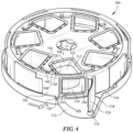
FIGURE 4 is another perspective view of the example detergent dispenser ofFIGURE 3 . -
FIGURE 5 is a perspective view of the example detergent dispenser ofFIGURE 3 disposed on a door of a dishwasher. -
FIGURE 6 is a lower perspective cross-sectional view of the example detergent dispenser ofFIGURE 3 disposed on a door of a dishwasher. -
FIGURE 7 is a perspective view of a carrier driver of the example detergent dispenser ofFIGURE 3 . -
FIGURE 8 is an exploded view of the example detergent dispenser ofFIGURE 3 disposed on a door of a dishwasher. -
FIGURE 9 is a schematic of another example detergent dispenser consistent with some embodiments of the invention. -
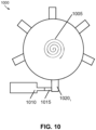
FIGURE 10 is a schematic of an example carrier driver of a detergent dispenser consistent with some embodiments of the invention. - Turning now to the drawings, wherein like numbers denote like parts throughout the several views,
Fig. 1 illustrates anexample dishwasher 10 in which the various technologies and techniques described herein may be implemented. Dishwasher 10 is a residential-type built-in dishwasher, and as such includes a front-mounteddoor 12 that provides access to awash tub 16 housed within the cabinet orhousing 14.Door 12 is generally hinged along a bottom edge and is pivotable between the opened position illustrated inFig. 1 and a closed position (not shown). Whendoor 12 is in the opened position, access is provided to one or more sliding racks, e.g.,lower rack 18 andupper rack 20, within which various utensils are placed for washing.Lower rack 18 may be supported onrollers 22, whileupper rack 20 may be supported onside rails 24, and each rack is movable between loading (extended) and washing (retracted) positions along a substantially horizontal direction. Control overdishwasher 10 by a user is generally managed through a control panel (not shown inFig. 1 ) typically disposed on a top or front ofdoor 12, and it will be appreciated that in different dishwasher designs, the control panel may include various types of input and/or output devices, including various knobs, buttons, lights, switches, textual and/or graphical displays, touch screens, etc. through which a user may configure one or more settings and start and stop a wash cycle. Additionally,dishwasher 10 may include one or more rotating spray arms, e.g.,lower spray arms 26,upper spray arm 28, or other sprayers, including various combinations of wall-mounted sprayers, rack-mounted sprayers, oscillating sprayers, fixed sprayers, rotating sprayers, focused sprayers, etc. However, this positioning is not intended to be limiting, as various sprayers may be positioned through the dishwasher. - In addition, consistent with some embodiments of the invention,
dishwasher 10 may include amovable detergent dispenser 29 with multiple dishwashing cycles' worth of detergent within thedispenser 29, so that it is not necessary for a user to add additional detergent before each dishwashing cycle. Such adetergent dispenser 29 may be positioned, as illustrated inFig. 1 , on the interior of thedoor 12. However, this positioning is not intended to be limiting, and in some embodiments the detergent dispenser may be positioned in other locations within the dishwasher. - The embodiments discussed hereinafter will focus on the implementation of the hereinafter-described techniques within a hinged-door dishwasher. However, it will be appreciated that the herein-described techniques may also be used in connection with other types of dishwashers in some embodiments. For example, the herein-described techniques may be used in commercial applications in some embodiments. Moreover, at least some of the herein-described techniques may be used in connection with other dishwasher configurations, including dishwashers utilizing sliding drawers or dish sink dishwashers, e.g., a dishwasher integrated into a sink.
- Now turning to
Fig. 2 ,dishwasher 10 may be under the control of acontroller 30 that receives inputs from a number of components and drives a number of components in response thereto.Controller 30 may, for example, include one or more processors and a memory (not shown) within which may be stored program code for execution by the one or more processors. The memory may be embedded incontroller 30, but may also be considered to include volatile and/or non-volatile memories, cache memories, flash memories, programmable read-only memories, read-only memories, etc., as well as memory storage physically located elsewhere fromcontroller 30, e.g., in a mass storage device or on a remote computer interfaced withcontroller 30. - As shown in
Fig. 2 ,controller 30 may be interfaced with various components of thedishwasher 10, including aninlet valve 32 that is coupled to a water source to introduce water intowash tub 16, which when combined with detergent, rinse agent and/or other additives, forms various wash fluids. Controller may also be coupled to aheater 34 that heats fluids, apump 36 that recirculates wash fluid within the wash tub by pumping fluid to the wash arms and other spray devices in the dishwasher, anair supply 38 that may provide a source of pressurized air for use in drying utensils in the dishwasher, adrain valve 40 that is coupled to a drain to direct fluids out of the dishwasher, and adiverter 42 that controls the routing of pumped fluid to different spray arms and/or other sprayers during a wash cycle. -
Controller 30 may also be coupled to thedetergent dispenser 29 to trigger the dispensing of detergent into the wash tub at appropriate points during a wash cycle. More particularly, thecontroller 30 may be coupled to a carrier driver of thedetergent dispenser 29, which may include one or more micro switches or a stepper motor in order to control and/or determine the positioning of the various detergent cavities (discussed in greater detail herein). Additional sensors and actuators may also be used in some embodiments, including atemperature sensor 46 to determine a wash fluid temperature, adoor switch 48 to determine whendoor 12 is latched, and adoor lock 50 to prevent the door from being opened during a wash cycle. Moreover,controller 30 may be coupled to a user interface 52 including various input/output devices such as knobs, dials, sliders, switches, buttons, lights, textual and/or graphics displays, touch screen displays, speakers, image capture devices, microphones, etc. for receiving input from and communicating with a user. In some embodiments,controller 30 may also be coupled to one or more network interfaces 54, e.g., for interfacing with external devices via wired and/or wireless networks such as Ethernet, Bluetooth, NFC, cellular and other suitable networks. - Moreover, in some embodiments, at least a portion of
controller 30 may be implemented externally from a dishwasher, e.g., within a mobile device, a cloud computing environment, etc., such that at least a portion of the functionality described herein is implemented within the portion of the controller that is externally implemented. In some embodiments,controller 30 may operate under the control of an operating system and may execute or otherwise rely upon various computer software applications, components, programs, objects, modules, data structures, etc. In addition,controller 30 may also incorporate hardware logic to implement some or all of the functionality disclosed herein. Further, in some embodiments, the sequences of operations performed bycontroller 30 to implement the embodiments disclosed herein may be implemented using program code including one or more instructions that are resident at various times in various memory and storage devices, and that, when read and executed by one or more hardware-based processors, perform the operations embodying desired functionality. Moreover, in some embodiments, such program code may be distributed as a program product in a variety of forms, and that the invention applies equally regardless of the particular type of computer readable media used to actually carry out the distribution, including, for example, non-transitory computer readable storage media. In addition, it will be appreciated that the various operations described herein may be combined, split, reordered, reversed, varied, omitted, parallelized and/or supplemented with other techniques known in the art, and therefore, the invention is not limited to the particular sequences of operations described herein. - Numerous variations and modifications to the
dishwasher 10 illustrated inFigs. 1 and2 will be apparent to one of ordinary skill in the art, as will become apparent from the description below. Therefore, the invention is not limited to the specific implementations discussed herein. - Now turning to
Figs. 3-5 , which illustrate anexample detergent dispenser 300 in which the various technologies and techniques described herein may be implemented. In some embodiments, thedetergent dispenser 300 may include adetergent carrier 302 and a housing 330 (described in greater detailer below) for receiving the detergent carrier. Thedetergent carrier 302 may include multiple detergent units 3041-n, each of which configured to hold a single wash cycle's worth of detergent. Each detergent unit 3041-n may include one or more walls defining acavity 306; for example, as illustrated inFigs. 3-4 , each detergent unit 3041-n includes afirst side wall 308, asecond side wall 310, athird side wall 312, and alower wall 314. Thefirst side wall 308,second side wall 310,third side wall 312, andlower wall 314 collectively define thecavity 306 having two openings: aloading opening 316 and adispensing opening 318. As illustrated inFigs. 3-5 , theloading opening 316 is disposed so as to be easily accessible to a user when thedoor 320 of the dishwasher is open in order to facilitate the loading process; however, the dispensingopening 318 is disposed so that when thedoor 320 of the dishwasher is closed the detergent contained therein will drop into the proper location within the wash tub when in a dispensing position. In some embodiments, each detergent unit 3041-n may additionally include an ejection mechanism used to eject the detergent into the proper location within the wash tub. In some embodiments, the dishwasher may spray water or other liquid into thecavity 306 in order to wash the detergent from thecavity 306. - In some embodiments, each detergent unit 3041-n of the
detergent carrier 302 may additionally contain an upper wall, such that only a single opening is defined. In such an embodiment, a single wash cycle worth of detergent may be loaded into the cavity and dispensed from the cavity using the same opening. - In some embodiments, the
detergent carrier 302 may be removable from thehousing 330 so that a user may load the detergent units 3041-n with detergent or clean thedetergent carrier 302 at a secondary location (e.g. a kitchen countertop, etc.). However, in other embodiments, thedetergent carrier 302 may be permanently affixed to thehousing 330. - As stated, each detergent unit 3041-n may be configured to hold one dishwashing cycle's worth of detergent; this includes detergent of all varieties, including, but not limited to, liquid detergent, powder detergent, and/or dissolvable pod or capsule detergent. As illustrated in
Figs. 3-4 , one of thedetergent units 3042 contains a dissolvable dishwashing pod/capsule 322. In some embodiments, thedetergent carrier 302 may include seven detergent units 3041-n, for example to correspond to the seven days of the week. In other embodiments, the detergent carrier may include five detergent units 3041-n. In still other embodiments, thedetergent carrier 302 may include any number of detergent units as is practical. - Furthermore, each detergent unit 3041-n includes a
door 324 or closure configured to cover thedispensing opening 318. Eachdoor 324 is moveable between an open position (e.g. when the detergent contained therein may be released) and a closed position. In some embodiments, eachdoor 324 may be spring-operated (for example through use of a torsional spring) for movement between the open and closed positions. In other embodiments, thedoor 324 may be moved between the open and closed positions by an actuator, solenoid, or any other mechanical means known in the art. In still other embodiments, thedoor 324 may be moved between the open and closed positions via a track that guides a guide, pin, wheel or other structure on the door coincident with movement of the carrier between different positions. - In some embodiments, each
door 324, loadingopening 316, and/or dispensingopening 318 of the detergent unit 3041-n may additionally include aseal 326 designed to minimize or prevent entry of water or other liquid into each of thecavities 306 when thedoor 324 is in a closed position. In some instances, theseseals 326 may utilize compression forces in order to seal the opening and prevent leakage. As a non-limiting example, theseseals 326 may be face seals, which are typically utilized to prevent leakage in the radial direction with respect to the axis of the seal. - In some embodiments, such as illustrated in
Figs. 3-5 , thedetergent dispenser 300 may include a track and guide system for facilitating movement of thedoor 324 of each detergent unit 3041-n between the open and closed positions. In such a system, eachdoor 324 may additionally include aguide 334, and thehousing 330 may additionally include atrack 336 that is configured to receive theguide 334 of eachdoor 324. In such embodiments, when adoor 324 of detergent unit 3041-n is closed, theguide 334 is in contact with thetrack 336, thus holding thedoor 324 in a closed position. In contrast, when aparticular door 324 is open theguide 334 is no longer in contact with thetrack 336, and as such thetrack 336 is no longer holding thedoor 324 in a closed position. In other embodiments, however, a track and guide may transition a door from a closed position to an open position, or vice versa, and as such a spring or other bias mechanism may not be used to bias a door to the open position in some embodiments. - In some instances, a spring-operated
door 324 that is biased to an open position may complement the use of such aguide 334 and track 336 system. For example, the physical contact of theguide 334 with thetrack 336 may provide the compression necessary to hold the spring-operated door 324 (biased to an open position) in a closed position. Once compression provided by thetrack 336 is removed, the spring-operateddoor 324 will move (e.g. spring to its biased position) to an open position. As illustrated inFigs. 3-5 , according to the invention, theguide 334 is in the form of a wheel affixed to thedoor 324, and thetrack 336 is in the form of a groove constructed as a part of thehousing 330. In such instances, the use of a wheel may reduce the friction generated by the contact of theguide 334 and thetrack 336, allowing thedetergent carrier 302 to more easily and smoothly move along thetrack 336 of thehousing 300. - In other instances, the
door 324 may not be spring-operated. In such instances, thetrack 336 may be shaped so as to guide thedoor 324 to an open position. For example, the broken line illustrated inFig. 3 indicates where thetrack 336 may be extended for use with a non-spring-operateddoor 324. - In some instances, it may be desirable to close a
particular door 324 after the detergent contained therein has been dispensed into the washtub of the dishwasher. As such, in some embodiments, thetrack 336 may additionally include acam 338 located near the dispensingopening 332 that is configured to engage thedoor 324 of the now-empty detergent unit 3041-n and facilitate thedoor 324 in moving from an open position to a closed position by providing force against the spring-operated door. - As briefly described previously, a housing 330 (removably or fixedly) receives the
detergent carrier 302. In some embodiments, thehousing 330 may be a separate component of thedetergent dispenser 300 separable from the dishwasher and thedetergent carrier 302; while in other embodiments, thehousing 330 may in incorporated (e.g. by molding or the like) directly into thedoor 320 of the dishwasher. Thehousing 330 may additionally include adispensing outlet 332 configured to guide or direct the detergent contained in each detergent unit 3041-n to the proper location within the washtub when dispensed. - The
detergent dispenser 300 may further include a carrier driver 602 (described in more detail with respect toFigs. 6-8 ) for moving thedetergent carrier 302 between multiple positions. For example, thedetergent carrier 302 is capable of being moved to position one of the detergent units 3041-n near the dispensingoutlet 332. When a particular detergent unit 3041-n is located near the dispensingoutlet 332 thedoor 324 of that particular detergent unit 3041-n may be open so as to allow for dispensing of the detergent contained therein. When a particular detergent unit 3041-n is not located near the dispensingoutlet 332 thedoor 324 of that particular detergent unit 3041-n may be closed and sealed so as to prevent the premature exit of the detergent contained therein, as well as to prevent the entry of water or other liquid into thecavity 306. Transitioning the detergent carrier between first and second positions may therefore move one detergent unit that is open and located near the dispensing outlet to a closed position in which the door is closed, while simultaneously moving the next detergent unit that is currently closed into the open position near the dispensing outlet to allow the door to open and dispense the detergent retained inside. - In some embodiments, such as illustrated in
Figs. 3-5 , thedetergent carrier 302 may rotate between the plurality of positions, such that the detergent units 3041-n are positioned in a generally circular manner. - In some embodiments, such as illustrated in
Fig. 9 , the movement of thedetergent carrier 902 between the plurality of positions may be linear, such that each of the detergent units 9041-n is disposed along a line. Similar to the embodiments described with reference toFigs. 3-5 , in a linear embodiment of adetergent dispenser 900 each detergent unit 9041-n may include a cavity defined by one or more walls and adoor 924 for holding detergent. In such an embodiment, thedetergent carrier 902 may slide along ahousing 930 as opposed to rotating in a generally circular manner. - Turning now to
Figs. 6-8 , each of which illustrates a different view of thedetergent dispenser 300. As mentioned previously, thedetergent dispenser 302 may include acarrier driver 602 that drives the movement of thedetergent carrier 302 between a plurality of positions. In some embodiments, thecarrier driver 602 may be a rotating motor that rotates thedetergent carrier 302 between multiple positions, so that at any point during the rotation one of the detergent units 3041-n may be positioned near the dispensingopening 332. In some instances, it may be desirable to use a stepper motor, which divides a full rotation into equal numbers of steps. In such instances, each detergent unit 3041-n may span a predetermined angle about the axis of rotation. Such an arrangement allows the stepper motor to control which one of the detergent units 3041-n is near the dispensingoutlet 332 by advancing the carrier a predetermined number of steps corresponding to that predetermined angle. In other embodiments, thecarrier driver 602 may be a motor that slides thedetergent carrier 302 linearly between multiple positions. - The
carrier driver 602 may, in some embodiments, be positioned partially (as illustrated inFig. 6 ) or wholly within an interior compartment of thedoor 320 of the dishwasher. In some instances, such a position may be desirable as a way of saving space and minimizing the overall size of thedetergent dispenser 300; such a position may also provide additional protection for thecarrier driver 602 from water or other liquid. In other embodiments, thecarrier driver 602 may be disposed on the interior surface of thedoor 320 of the dishwasher with the remainder of thedetergent dispenser 300. - In some embodiments, the
carrier driver 602 may include one or moremicro switches 604 that are configured to detect if one of the detergent units 3041-n is near the dispensingoutlet 332. These micro switches, if present, may be actuated through minimal physical force by use of a tipping-point mechanism, and as such they may, in some instances, be desirable for the detection of a location of a detergent unit 3041-n. In such embodiments, therefore, a motor other than a stepper motor may be used to rotate the carrier. Further, in some embodiments, other drives may be used to perform the rotation, e.g., a solenoid and ratchet arrangement that indexes the carrier to a next position upon each actuation of the solenoid. - In other embodiments, such as illustrated in
Fig. 10 , thecarrier driver 1000 may be a user-pretensioned spring 1005 (e.g. a clock spring) that may allow energy to be provided by a user and then be stored and used in order to change the position of a detergent unit (not illustrated inFig. 10 ) between an open position and a closed position or vice versa. In such an embodiment, a user may "wind up" the pretensioned-spring 1005 at the time the detergent units of the detergent carrier are loaded. Asolenoid 1010 may then push apawl 1015 in order to release a ratcheted segment 10201-n, where each ratcheted segment 10201-n corresponds to a detergent unit, which is in either an open or a closed position. For example,Fig. 10 illustrates six ratcheted segments 10201-n, which would correspond to six detergent units; this is not to be understood as limiting, as the number of ratcheted segments 10201-n and corresponding detergent units may vary. - In some instances, particularly in embodiments where the detergent units 3041-n include a
loading opening 316, thedetergent dispenser 300 may additionally include aremovable lid 606. Such aremovable lid 606 may be configured to seal thecavity 306 at each of theloading openings 316 and minimize and/or prevent the entry of water or other liquid into eachcavity 306 of the detergent units 3041-n. In some instances, thelid 606 may use compression sealing, which may reduce friction while also ensuring that thecavities 306 of the detergent units 3041-n are sealed. Additionally, thelid 606 may also include one or morelatching protrusions 608 that are configured to be received by acorresponding void 340 of thedetergent carrier 302 in order to form a watertight seal. In some embodiments, thevoid 340 and latchingprotrusion 608 are shaped so as to require movement (e.g. twisting, rotation, or the like) of thelid 606 by a user in order for a seal to be formed, which allows for a user to easily apply and remove thelid 606 with a simple motion. As such, it may be desirable in some instances for the lid to further contain ahandle 610 or a gripping point for a user. Additionally, thelid 606, particularly when attached through the use of latchingprotrusions 608, may move with thedetergent carrier 302 as it moves. In some embodiments, such as illustrated inFigs. 3-5 , each detergent unit 3041-n includes a void 340 corresponding to a latchingprotrusions 608 on thelid 606, so that there is a seal at each detergent unit 3041-n. - In some embodiments, the
lid 606 may be constructed of a translucent material so that a user may be able to view the contents of each detergent unit 3041-n. In other embodiments, thelid 606 may be colored so as to match the remainder of thedetergent dispenser 300 and/or thedoor 320 of the dishwasher so as to be aesthetically pleasing to a user. In still other embodiments, thelid 606 may be any other color or opacity desired. In still other embodiments, the carrier may be permanently mounted to and enveloped by the housing, and no separate lid may be used. In such embodiments, each detergent unit may be loaded sequentially, e.g., through the dispensing outlet or through a separate loading outlet disposed at another radial position around the housing (e.g., proximate a top of the dishwasher door to facilitate loading by the user). - Although described herein with respect to a dishwasher, this is not intended to be limiting. The technology and techniques disclosed herein may be utilized in any household appliance that requires dispensing of a detergent, such as, for example a washing machine.
- Various additional modifications may be made to the illustrated embodiments consistent with the invention. Therefore, the invention lies in the claims hereinafter appended.
Claims (15)
- A detergent dispenser (29, 300) to be positioned to dispense detergent into a household appliance, including:a detergent carrier (302, 902) including a plurality of detergent units (3041-n), each of the detergent units (3041-n) including:one or more walls (308, 310, 312, 314) defining a cavity (306) having a dispensing opening (318), anda door (324) movable between an open position and a closed position,a housing (330, 930) configured to receive the detergent carrier (302, 902), the housing (330, 930) including a dispensing outlet (332),wherein when one of the plurality of detergent units (3041-n) is proximate the dispensing outlet (332) the door (324) of the one of the plurality of detergent units (3041-n) is open, otherwise the door (324) is closed, characterised in that the door (324) of each of the detergent units (3041-n) further includes a guide (334) in the form of a wheel affixed to the door, and the housing (330, 930) further includes a track (336) configured to receive the guide (334) of each said door (324), wherein said track (336) is in the form of a groove constructed as a part of the housing.
a carrier driver (602, 1000) configured to move the detergent carrier (302, 902) between a plurality of positions, each position orienting one of the plurality of detergent units(3041-n) proximate the dispensing outlet (332), - The detergent dispenser (29, 300) of claim 1, wherein the track (336) is arranged and configured such that for the door (324) of each detergent unit (3041-n) that is not oriented proximate the dispensing outlet (332), the guide (334) of such door (324) is received within the track (336) to position such door (324) in the closed position.
- The detergent dispenser (29, 300) of claim 1, wherein the plurality of positions includes a first position where a first detergent unit among the plurality of detergent units (3041-n) is oriented proximate the dispensing outlet (332) and a second position where a second unit among the plurality of detergent units (3041-n) is oriented proximate the dispensing outlet (332), wherein the track (336) is arranged and configured such that when the carrier driver (602, 1000) moves the detergent carrier (302, 902) from the first position to the second position, the track (336) guides the door (324) of the first detergent unit from the open position to the closed position and guides the door (324) of the second detergent unit from the closed position to the open position.
- The detergent dispenser (29, 300) of claim 1, wherein each door (324) is biased to the open position, wherein the plurality of positions includes a first position where a first detergent unit among the plurality of detergent units (3041-n) is oriented proximate the dispensing outlet (332) and a second position where a second unit among the plurality of detergent units (3041-n) is oriented proximate the dispensing outlet (332), wherein the track (336) is arranged and configured such that when the carrier driver (602, 1000) moves the detergent carrier (302, 902) from the first position to the second position, the track (336) guides the door (324) of the first detergent unit from the open position to the closed position and releases the door (324) of the second detergent unit such that the bias of the door (324) of the second detergent unit moves the door (324) of the second detergent unit from the closed position to the open position.
- The detergent dispenser (29, 300) of any one of claim 1 to 4, wherein the housing (330, 930) further includes a cam (338) disposed proximate the dispensing opening (318) and configured to move the door (324) from the open position to the closed position following dispensing of detergent, and/orwherein each detergent unit (3041-n) includes a spring that biases the door (324) for such detergent unit (3041-n) to the open position, and/orwherein each detergent unit (3041-n) further includes a seal (326) coupled to one of the door (324) for such detergent unit and the dispensing opening (318) for such detergent unit (3041-n) to seal the cavity (306) of such detergent unit (3041-n) when the door (324) of such detergent unit (3041-n) is in a closed position.
- The detergent dispenser (29, 300) of any one of claims 1 to 5, wherein the cavity (306) of each detergent unit (3041-n) further includes a loading opening (316).
- The detergent dispenser (29, 300) of claim 6, further including a removable lid (606) and a seal coupled to one of the detergent carrier (302, 902) and the removable lid (606) to seal the loading opening (316) of each detergent unit (3041-n) when the removable lid (606) is secured to the detergent dispenser (29, 300), and
wherein the removable lid (606) moves with the detergent carrier (302, 902). - The detergent dispenser (29, 300) of any one of claims 1 to 7, wherein the carrier driver (602, 1000) includes a motor that rotates the detergent carrier (302, 902) between the plurality of positions.
- The detergent dispenser (29, 300) of claim 9, wherein the motor is a stepper motor.
- The detergent dispenser (29, 300) of any one of claims 1 to 9, wherein the carrier driver (602, 1000) includes one or more micro switches (604) configured to detect if one of the plurality of detergent units (3041-n) is proximate the dispensing outlet (332), or
wherein the carrier driver (602, 1000) includes a user-pretensioned spring (1005) and a solenoid (1010). - A dishwasher (10), comprising:a wash tub (16); andthe detergent dispenser (29, 300) according to claim 1, positioned to dispense detergent into the wash tub, wherein the detergent dispenser (29, 300) is a rotating detergent dispenser,wherein, with respect to each of the detergent units :the cavity (306) further comprises a loading opening (316),the door (324) is biased to the open position, and wherein each of the detergent units (3041-n) further comprises:
a seal (326) coupled to one of the door (324) for such detergent unit (3041-n) and the dispensing opening (318) for such detergent unit (3041-n) to seal the cavity (306) of such detergent unit (3041-n) when the door (324) of such detergent unit (3041-n) is in a closed position,a removable lid (606) and a seal coupled to one of the detergent carrier (302, 902) and the removable lid to seal the loading opening (316) of each detergent unit (3041-n) when the removable lid (606) is secured to the detergent dispenser (29, 300),and whereinthe carrier driver (602, 1000) is configured to rotate the detergent carrier (302, 902) between a plurality of positions, each position orienting one of the plurality of detergent units (3041-n) proximate the dispensing outlet (332). - The dishwasher of claim 11, wherein the carrier driver (602, 1000) includes one or more micro switches (604) configured to detect if one of the plurality of detergent units (3041-n) is proximate the dispensing outlet (332), orwherein the carrier driver (602, 1000) includes a stepper motor, orwherein the housing (330, 930) further includes a cam (338) disposed proximate the dispensing opening (318) and configured to move the door (324) from the open position to the closed position following dispensing of detergent.
- The detergent dispenser (29, 300) of any of claims 1 to 10, wherein the household appliance is a dishwasher (10) and the housing (330, 930) is coupled to a dishwasher door (324) that provides external access to the dishwasher, or
wherein the household appliance is a washing machine. - A household appliance comprising the detergent dispenser (29, 300) according to any of claims 1 to 10, wherein the detergent dispenser (29, 300) is positioned to dispense detergent into the household appliance.
- A dishwasher (10) comprising a wash tub (16) and the detergent dispenser (29, 300) according to any of claims 1 to 10, wherein the detergent dispenser (29, 300) is positioned to dispense detergent into the wash tub (16).
Applications Claiming Priority (2)
| Application Number | Priority Date | Filing Date | Title |
|---|---|---|---|
| US16/215,030 US11019982B2 (en) | 2018-12-10 | 2018-12-10 | Multiple use detergent dispenser |
| PCT/CN2019/097405 WO2020119128A1 (en) | 2018-12-10 | 2019-07-24 | Multiple use detergent dispenser |
Publications (3)
| Publication Number | Publication Date |
|---|---|
| EP3864213A1 EP3864213A1 (en) | 2021-08-18 |
| EP3864213A4 EP3864213A4 (en) | 2021-09-22 |
| EP3864213B1 true EP3864213B1 (en) | 2024-09-25 |
Family
ID=70972313
Family Applications (1)
| Application Number | Title | Priority Date | Filing Date |
|---|---|---|---|
| EP19897392.7A Active EP3864213B1 (en) | 2018-12-10 | 2019-07-24 | Multiple use detergent dispenser |
Country Status (4)
| Country | Link |
|---|---|
| US (1) | US11019982B2 (en) |
| EP (1) | EP3864213B1 (en) |
| CN (1) | CN113167006B (en) |
| WO (1) | WO2020119128A1 (en) |
Families Citing this family (9)
| Publication number | Priority date | Publication date | Assignee | Title |
|---|---|---|---|---|
| DE102016125843A1 (en) * | 2016-12-29 | 2018-07-05 | Sanhua Aweco Appliance Systems Gmbh | Device for dispensing cleaning agents |
| EP4360530A4 (en) * | 2021-02-01 | 2025-01-01 | Foshan Shunde Midea Washing Appliances Manufacturing Co., Ltd. | DISPENSER FOR DISHWASHER AND DISHWASHER THEREFORE |
| DE102021112035A1 (en) * | 2021-05-07 | 2022-11-10 | Emz-Hanauer Gmbh & Co. Kgaa | Lid assembly for mounting in a domestic dishwasher |
| KR20240064464A (en) | 2022-11-04 | 2024-05-13 | 삼성전자주식회사 | Dish washer |
| KR20240064455A (en) | 2022-11-04 | 2024-05-13 | 삼성전자주식회사 | Dish washer |
| KR20240064466A (en) | 2022-11-04 | 2024-05-13 | 삼성전자주식회사 | Dish washer |
| KR20240064463A (en) | 2022-11-04 | 2024-05-13 | 삼성전자주식회사 | Dish washer |
| EP4578366A1 (en) * | 2023-12-28 | 2025-07-02 | Arçelik Anonim Sirketi | A dishwasher comprising a detergent dosing unit |
| BE1032375B1 (en) * | 2024-02-01 | 2025-09-01 | Miele & Cie | Dosing device |
Family Cites Families (26)
| Publication number | Priority date | Publication date | Assignee | Title |
|---|---|---|---|---|
| US3567076A (en) | 1967-05-20 | 1971-03-02 | Zanussi A Spa Industrie | Rotary distributor assembly for washing machines |
| DE1785623C3 (en) | 1967-11-02 | 1980-03-06 | Bosch-Siemens Hausgeraete Gmbh, 7000 Stuttgart | Detergent dispenser |
| GB8703368D0 (en) | 1987-02-13 | 1987-03-18 | Currys Group Plc | Loading apparatus |
| US5261432A (en) | 1990-10-03 | 1993-11-16 | Ro-Sa Micromeccanica S.N.C. | Dishwashing machine with multidose dispenser of powder detergent |
| GB2386129B (en) * | 2002-03-06 | 2004-12-01 | Reckitt Benckiser Nv | Detergent dosing device |
| GB2386130A (en) | 2002-03-06 | 2003-09-10 | Reckitt Benckiser Nv | Detergent dosing delay device for a dishwasher |
| US6962266B2 (en) * | 2002-10-04 | 2005-11-08 | Ecolab Inc. | Method and apparatus for using a unit dose dispenser |
| EP1493375A1 (en) | 2003-07-04 | 2005-01-05 | Bonferraro S.p.A. | Multidose detergent dispenser for dishwasher |
| ITTO20040041A1 (en) * | 2004-01-29 | 2004-04-29 | Elbi Int Spa | DISPENSER OF A WASHING AGENT, AND PARTICULARLY FOR A DISHWASHER MACHINE |
| KR100578035B1 (en) * | 2004-06-23 | 2006-05-11 | 박재태 | Food or Drug Dispensers |
| BRPI0514561A (en) | 2004-08-23 | 2008-06-17 | Reckitt Benckiser Nv | detergent dispensing device |
| EP1976421B1 (en) | 2006-01-21 | 2017-06-21 | Reckitt Benckiser Finish B.V. | An article for use in a ware washing machine |
| GB0621572D0 (en) | 2006-10-30 | 2006-12-06 | Reckitt Benckiser Nv | Multi-dosing detergent delivery device |
| KR100873681B1 (en) | 2007-05-28 | 2008-12-12 | 엘지전자 주식회사 | Top Load Washer |
| ITMI20071667A1 (en) * | 2007-08-10 | 2009-02-11 | Reckitt Benckiser Nv | DELIVERY SUPPORT FOR A DISPENSER OF SUBSTANCES, IN PARTICULAR WASHING AGENTS |
| EP2380478A1 (en) * | 2010-04-23 | 2011-10-26 | The Procter & Gamble Company | Automatic dishwashing product |
| ES2533368T3 (en) | 2010-04-23 | 2015-04-09 | The Procter & Gamble Company | Dishwasher product |
| KR20120039798A (en) * | 2010-10-18 | 2012-04-26 | 윤문한 | Medicines safekeeping equipment |
| CN203247428U (en) | 2013-03-22 | 2013-10-23 | 无锡小天鹅股份有限公司 | Washing machine and detergent adding pump assembly thereof |
| CN103276563B (en) | 2013-05-07 | 2016-05-25 | 无锡小天鹅股份有限公司 | Washing machine and washing agent thereof are thrown in assembly |
| DE102013110401A1 (en) * | 2013-09-20 | 2015-03-26 | Miele & Cie. Kg | Method for operating a dosing device of a dishwasher |
| US9717393B2 (en) | 2014-06-12 | 2017-08-01 | Whirlpool Corporation | Household appliance with bulk unit-dose dispenser |
| DE102016210398A1 (en) | 2016-06-13 | 2017-12-14 | BSH Hausgeräte GmbH | Dosing device for detergent tablets in household dishwashers |
| US10161074B2 (en) | 2016-06-30 | 2018-12-25 | Midea Group Co., Ltd. | Laundry washing machine with automatic detergent dispensing and/or rinse operation type selection |
| CN106400407B (en) | 2016-08-31 | 2019-06-18 | 无锡小天鹅股份有限公司 | The automatic jettison system of washing machine and washing machine with it |
| CN108951007B (en) | 2017-05-27 | 2021-06-01 | 无锡小天鹅电器有限公司 | Automatic putting device of washing machine and washing machine with automatic putting device |
-
2018
- 2018-12-10 US US16/215,030 patent/US11019982B2/en active Active
-
2019
- 2019-07-24 EP EP19897392.7A patent/EP3864213B1/en active Active
- 2019-07-24 WO PCT/CN2019/097405 patent/WO2020119128A1/en not_active Ceased
- 2019-07-24 CN CN201980078020.1A patent/CN113167006B/en active Active
Also Published As
| Publication number | Publication date |
|---|---|
| US11019982B2 (en) | 2021-06-01 |
| EP3864213A1 (en) | 2021-08-18 |
| US20200178756A1 (en) | 2020-06-11 |
| CN113167006B (en) | 2026-06-19 |
| EP3864213A4 (en) | 2021-09-22 |
| WO2020119128A1 (en) | 2020-06-18 |
| CN113167006A (en) | 2021-07-23 |
Similar Documents
| Publication | Publication Date | Title |
|---|---|---|
| US11019982B2 (en) | Multiple use detergent dispenser | |
| US11497380B2 (en) | Detergent cartridge for a dishwasher incorporating detergent dispensing verification | |
| US12029372B2 (en) | Detergent cartridge for a dishwasher | |
| US11147431B2 (en) | Detergent dispenser for a dishwasher | |
| US7337635B2 (en) | Washing agent dispenser for a domestic washing machine, namely a dishwasher | |
| US20150122298A1 (en) | Mid-level spray arm assembly for dishwasher appliances | |
| US8292381B2 (en) | Consumer appliance such as dishwasher with soft open door mechanism | |
| ITTO20000300A1 (en) | DEVICE DISPENSER OF WASHING AGENTS FOR A DOMESTIC WASHING MACHINE, IN PARTICULAR A DISHWASHER. | |
| US11717133B2 (en) | Dishwasher with rotary blister pack dispenser | |
| US9307886B2 (en) | Indexing passive diverter for an appliance | |
| US11035072B2 (en) | Washing machine appliance and nozzle assembly | |
| EP3135180B1 (en) | A dishwasher comprising a liquid/gel dosing unit | |
| US9795271B2 (en) | Variable position hydraulically actuated diverter for an appliance | |
| US7699063B2 (en) | Dispenser for a drawer-type dishwasher | |
| EP2478819B1 (en) | A washing agent dispensing device for a washing machine for household use, in particular a dishwasher, and washing machine thereof | |
| US11091871B2 (en) | Pivoted faucet in a lid of a top load washing machine | |
| EP2918215B1 (en) | Dishwasher including detergent dispenser | |
| EP1245180A2 (en) | Household dishwashing machine with dispenser device for washing agents | |
| RU2713372C1 (en) | Home appliance with movable control panel and method of such device operation | |
| EP2941167A2 (en) | A dishwasher | |
| US11802362B2 (en) | Laundry appliance with improved drawer | |
| US20250261821A1 (en) | Dishwasher with integrated utensil rinsing device | |
| ITTO20010085A1 (en) | DOMESTIC DISHWASHER MACHINE WITH WASHING AGENT DISPENSER AND RELATED WASHING PROGRAM. | |
| US20190257022A1 (en) | Passive diverter for an auxiliary spray device of a washing machine appliance | |
| CN110279380A (en) | Dispensing units and washing appliances |
Legal Events
| Date | Code | Title | Description |
|---|---|---|---|
| STAA | Information on the status of an ep patent application or granted ep patent |
Free format text: STATUS: THE INTERNATIONAL PUBLICATION HAS BEEN MADE |
|
| PUAI | Public reference made under article 153(3) epc to a published international application that has entered the european phase |
Free format text: ORIGINAL CODE: 0009012 |
|
| STAA | Information on the status of an ep patent application or granted ep patent |
Free format text: STATUS: REQUEST FOR EXAMINATION WAS MADE |
|
| 17P | Request for examination filed |
Effective date: 20210513 |
|
| AK | Designated contracting states |
Kind code of ref document: A1 Designated state(s): AL AT BE BG CH CY CZ DE DK EE ES FI FR GB GR HR HU IE IS IT LI LT LU LV MC MK MT NL NO PL PT RO RS SE SI SK SM TR |
|
| REG | Reference to a national code |
Ref country code: DE Ref legal event code: R079 Free format text: PREVIOUS MAIN CLASS: D06F0039020000 Ipc: A47L0015440000 Ref document number: 602019059588 Country of ref document: DE |
|
| A4 | Supplementary search report drawn up and despatched |
Effective date: 20210825 |
|
| RIC1 | Information provided on ipc code assigned before grant |
Ipc: A47L 15/42 20060101ALN20210819BHEP Ipc: D06F 39/02 20060101ALI20210819BHEP Ipc: A47L 15/44 20060101AFI20210819BHEP |
|
| DAV | Request for validation of the european patent (deleted) | ||
| DAX | Request for extension of the european patent (deleted) | ||
| STAA | Information on the status of an ep patent application or granted ep patent |
Free format text: STATUS: EXAMINATION IS IN PROGRESS |
|
| 17Q | First examination report despatched |
Effective date: 20240205 |
|
| GRAP | Despatch of communication of intention to grant a patent |
Free format text: ORIGINAL CODE: EPIDOSNIGR1 |
|
| STAA | Information on the status of an ep patent application or granted ep patent |
Free format text: STATUS: GRANT OF PATENT IS INTENDED |
|
| RIC1 | Information provided on ipc code assigned before grant |
Ipc: A47L 15/42 20060101ALN20240507BHEP Ipc: D06F 39/02 20060101ALI20240507BHEP Ipc: A47L 15/44 20060101AFI20240507BHEP |
|
| INTG | Intention to grant announced |
Effective date: 20240528 |
|
| GRAS | Grant fee paid |
Free format text: ORIGINAL CODE: EPIDOSNIGR3 |
|
| GRAA | (expected) grant |
Free format text: ORIGINAL CODE: 0009210 |
|
| STAA | Information on the status of an ep patent application or granted ep patent |
Free format text: STATUS: THE PATENT HAS BEEN GRANTED |
|
| AK | Designated contracting states |
Kind code of ref document: B1 Designated state(s): AL AT BE BG CH CY CZ DE DK EE ES FI FR GB GR HR HU IE IS IT LI LT LU LV MC MK MT NL NO PL PT RO RS SE SI SK SM TR |
|
| REG | Reference to a national code |
Ref country code: GB Ref legal event code: FG4D |
|
| REG | Reference to a national code |
Ref country code: CH Ref legal event code: EP |
|
| REG | Reference to a national code |
Ref country code: DE Ref legal event code: R096 Ref document number: 602019059588 Country of ref document: DE |
|
| REG | Reference to a national code |
Ref country code: IE Ref legal event code: FG4D |
|
| REG | Reference to a national code |
Ref country code: LT Ref legal event code: MG9D |
|
| PG25 | Lapsed in a contracting state [announced via postgrant information from national office to epo] |
Ref country code: NO Free format text: LAPSE BECAUSE OF FAILURE TO SUBMIT A TRANSLATION OF THE DESCRIPTION OR TO PAY THE FEE WITHIN THE PRESCRIBED TIME-LIMIT Effective date: 20241225 |
|
| PG25 | Lapsed in a contracting state [announced via postgrant information from national office to epo] |
Ref country code: GR Free format text: LAPSE BECAUSE OF FAILURE TO SUBMIT A TRANSLATION OF THE DESCRIPTION OR TO PAY THE FEE WITHIN THE PRESCRIBED TIME-LIMIT Effective date: 20241226 Ref country code: FI Free format text: LAPSE BECAUSE OF FAILURE TO SUBMIT A TRANSLATION OF THE DESCRIPTION OR TO PAY THE FEE WITHIN THE PRESCRIBED TIME-LIMIT Effective date: 20240925 |
|
| PG25 | Lapsed in a contracting state [announced via postgrant information from national office to epo] |
Ref country code: BG Free format text: LAPSE BECAUSE OF FAILURE TO SUBMIT A TRANSLATION OF THE DESCRIPTION OR TO PAY THE FEE WITHIN THE PRESCRIBED TIME-LIMIT Effective date: 20240925 |
|
| PG25 | Lapsed in a contracting state [announced via postgrant information from national office to epo] |
Ref country code: LV Free format text: LAPSE BECAUSE OF FAILURE TO SUBMIT A TRANSLATION OF THE DESCRIPTION OR TO PAY THE FEE WITHIN THE PRESCRIBED TIME-LIMIT Effective date: 20240925 |
|
| PG25 | Lapsed in a contracting state [announced via postgrant information from national office to epo] |
Ref country code: RS Free format text: LAPSE BECAUSE OF FAILURE TO SUBMIT A TRANSLATION OF THE DESCRIPTION OR TO PAY THE FEE WITHIN THE PRESCRIBED TIME-LIMIT Effective date: 20241225 |
|
| REG | Reference to a national code |
Ref country code: NL Ref legal event code: MP Effective date: 20240925 |
|
| PG25 | Lapsed in a contracting state [announced via postgrant information from national office to epo] |
Ref country code: RS Free format text: LAPSE BECAUSE OF FAILURE TO SUBMIT A TRANSLATION OF THE DESCRIPTION OR TO PAY THE FEE WITHIN THE PRESCRIBED TIME-LIMIT Effective date: 20241225 Ref country code: NO Free format text: LAPSE BECAUSE OF FAILURE TO SUBMIT A TRANSLATION OF THE DESCRIPTION OR TO PAY THE FEE WITHIN THE PRESCRIBED TIME-LIMIT Effective date: 20241225 Ref country code: LV Free format text: LAPSE BECAUSE OF FAILURE TO SUBMIT A TRANSLATION OF THE DESCRIPTION OR TO PAY THE FEE WITHIN THE PRESCRIBED TIME-LIMIT Effective date: 20240925 Ref country code: GR Free format text: LAPSE BECAUSE OF FAILURE TO SUBMIT A TRANSLATION OF THE DESCRIPTION OR TO PAY THE FEE WITHIN THE PRESCRIBED TIME-LIMIT Effective date: 20241226 Ref country code: FI Free format text: LAPSE BECAUSE OF FAILURE TO SUBMIT A TRANSLATION OF THE DESCRIPTION OR TO PAY THE FEE WITHIN THE PRESCRIBED TIME-LIMIT Effective date: 20240925 Ref country code: BG Free format text: LAPSE BECAUSE OF FAILURE TO SUBMIT A TRANSLATION OF THE DESCRIPTION OR TO PAY THE FEE WITHIN THE PRESCRIBED TIME-LIMIT Effective date: 20240925 |
|
| REG | Reference to a national code |
Ref country code: AT Ref legal event code: MK05 Ref document number: 1725924 Country of ref document: AT Kind code of ref document: T Effective date: 20240925 |
|
| PG25 | Lapsed in a contracting state [announced via postgrant information from national office to epo] |
Ref country code: NL Free format text: LAPSE BECAUSE OF FAILURE TO SUBMIT A TRANSLATION OF THE DESCRIPTION OR TO PAY THE FEE WITHIN THE PRESCRIBED TIME-LIMIT Effective date: 20240925 |
|
| PG25 | Lapsed in a contracting state [announced via postgrant information from national office to epo] |
Ref country code: PT Free format text: LAPSE BECAUSE OF FAILURE TO SUBMIT A TRANSLATION OF THE DESCRIPTION OR TO PAY THE FEE WITHIN THE PRESCRIBED TIME-LIMIT Effective date: 20250127 Ref country code: IS Free format text: LAPSE BECAUSE OF FAILURE TO SUBMIT A TRANSLATION OF THE DESCRIPTION OR TO PAY THE FEE WITHIN THE PRESCRIBED TIME-LIMIT Effective date: 20250125 |
|
| PG25 | Lapsed in a contracting state [announced via postgrant information from national office to epo] |
Ref country code: SM Free format text: LAPSE BECAUSE OF FAILURE TO SUBMIT A TRANSLATION OF THE DESCRIPTION OR TO PAY THE FEE WITHIN THE PRESCRIBED TIME-LIMIT Effective date: 20240925 Ref country code: RO Free format text: LAPSE BECAUSE OF FAILURE TO SUBMIT A TRANSLATION OF THE DESCRIPTION OR TO PAY THE FEE WITHIN THE PRESCRIBED TIME-LIMIT Effective date: 20240925 |
|
| PG25 | Lapsed in a contracting state [announced via postgrant information from national office to epo] |
Ref country code: ES Free format text: LAPSE BECAUSE OF FAILURE TO SUBMIT A TRANSLATION OF THE DESCRIPTION OR TO PAY THE FEE WITHIN THE PRESCRIBED TIME-LIMIT Effective date: 20240925 |
|
| PG25 | Lapsed in a contracting state [announced via postgrant information from national office to epo] |
Ref country code: EE Free format text: LAPSE BECAUSE OF FAILURE TO SUBMIT A TRANSLATION OF THE DESCRIPTION OR TO PAY THE FEE WITHIN THE PRESCRIBED TIME-LIMIT Effective date: 20240925 Ref country code: AT Free format text: LAPSE BECAUSE OF FAILURE TO SUBMIT A TRANSLATION OF THE DESCRIPTION OR TO PAY THE FEE WITHIN THE PRESCRIBED TIME-LIMIT Effective date: 20240925 |
|
| PG25 | Lapsed in a contracting state [announced via postgrant information from national office to epo] |
Ref country code: CZ Free format text: LAPSE BECAUSE OF FAILURE TO SUBMIT A TRANSLATION OF THE DESCRIPTION OR TO PAY THE FEE WITHIN THE PRESCRIBED TIME-LIMIT Effective date: 20240925 Ref country code: PL Free format text: LAPSE BECAUSE OF FAILURE TO SUBMIT A TRANSLATION OF THE DESCRIPTION OR TO PAY THE FEE WITHIN THE PRESCRIBED TIME-LIMIT Effective date: 20240925 |
|
| PG25 | Lapsed in a contracting state [announced via postgrant information from national office to epo] |
Ref country code: IT Free format text: LAPSE BECAUSE OF FAILURE TO SUBMIT A TRANSLATION OF THE DESCRIPTION OR TO PAY THE FEE WITHIN THE PRESCRIBED TIME-LIMIT Effective date: 20240925 Ref country code: SK Free format text: LAPSE BECAUSE OF FAILURE TO SUBMIT A TRANSLATION OF THE DESCRIPTION OR TO PAY THE FEE WITHIN THE PRESCRIBED TIME-LIMIT Effective date: 20240925 |
|
| REG | Reference to a national code |
Ref country code: DE Ref legal event code: R097 Ref document number: 602019059588 Country of ref document: DE |
|
| PG25 | Lapsed in a contracting state [announced via postgrant information from national office to epo] |
Ref country code: DK Free format text: LAPSE BECAUSE OF FAILURE TO SUBMIT A TRANSLATION OF THE DESCRIPTION OR TO PAY THE FEE WITHIN THE PRESCRIBED TIME-LIMIT Effective date: 20240925 |
|
| PLBE | No opposition filed within time limit |
Free format text: ORIGINAL CODE: 0009261 |
|
| STAA | Information on the status of an ep patent application or granted ep patent |
Free format text: STATUS: NO OPPOSITION FILED WITHIN TIME LIMIT |
|
| 26N | No opposition filed |
Effective date: 20250626 |
|
| PG25 | Lapsed in a contracting state [announced via postgrant information from national office to epo] |
Ref country code: SE Free format text: LAPSE BECAUSE OF FAILURE TO SUBMIT A TRANSLATION OF THE DESCRIPTION OR TO PAY THE FEE WITHIN THE PRESCRIBED TIME-LIMIT Effective date: 20240925 |
|
| PGFP | Annual fee paid to national office [announced via postgrant information from national office to epo] |
Ref country code: DE Payment date: 20250724 Year of fee payment: 7 |
|
| PGFP | Annual fee paid to national office [announced via postgrant information from national office to epo] |
Ref country code: GB Payment date: 20250722 Year of fee payment: 7 |
|
| PGFP | Annual fee paid to national office [announced via postgrant information from national office to epo] |
Ref country code: FR Payment date: 20250722 Year of fee payment: 7 |
|
| PG25 | Lapsed in a contracting state [announced via postgrant information from national office to epo] |
Ref country code: HR Free format text: LAPSE BECAUSE OF FAILURE TO SUBMIT A TRANSLATION OF THE DESCRIPTION OR TO PAY THE FEE WITHIN THE PRESCRIBED TIME-LIMIT Effective date: 20240925 |
|
| REG | Reference to a national code |
Ref country code: CH Ref legal event code: H13 Free format text: ST27 STATUS EVENT CODE: U-0-0-H10-H13 (AS PROVIDED BY THE NATIONAL OFFICE) Effective date: 20260224 |
|
| PG25 | Lapsed in a contracting state [announced via postgrant information from national office to epo] |
Ref country code: LU Free format text: LAPSE BECAUSE OF NON-PAYMENT OF DUE FEES Effective date: 20250724 |
|
| REG | Reference to a national code |
Ref country code: BE Ref legal event code: MM Effective date: 20250731 |
|
| PG25 | Lapsed in a contracting state [announced via postgrant information from national office to epo] |
Ref country code: BE Free format text: LAPSE BECAUSE OF NON-PAYMENT OF DUE FEES Effective date: 20250731 |
|
| PG25 | Lapsed in a contracting state [announced via postgrant information from national office to epo] |
Ref country code: CH Free format text: LAPSE BECAUSE OF NON-PAYMENT OF DUE FEES Effective date: 20250731 |
|
| PG25 | Lapsed in a contracting state [announced via postgrant information from national office to epo] |
Ref country code: LT Free format text: LAPSE BECAUSE OF FAILURE TO SUBMIT A TRANSLATION OF THE DESCRIPTION OR TO PAY THE FEE WITHIN THE PRESCRIBED TIME-LIMIT Effective date: 20240925 |
|
| PG25 | Lapsed in a contracting state [announced via postgrant information from national office to epo] |
Ref country code: IE Free format text: LAPSE BECAUSE OF NON-PAYMENT OF DUE FEES Effective date: 20250724 |
|
| PG25 | Lapsed in a contracting state [announced via postgrant information from national office to epo] |
Ref country code: MC Free format text: LAPSE BECAUSE OF FAILURE TO SUBMIT A TRANSLATION OF THE DESCRIPTION OR TO PAY THE FEE WITHIN THE PRESCRIBED TIME-LIMIT Effective date: 20240925 |
|
| PG25 | Lapsed in a contracting state [announced via postgrant information from national office to epo] |
Ref country code: CY Free format text: LAPSE BECAUSE OF FAILURE TO SUBMIT A TRANSLATION OF THE DESCRIPTION OR TO PAY THE FEE WITHIN THE PRESCRIBED TIME-LIMIT Effective date: 20240925 |