EP3863742B1 - System, chip tray, and method - Google Patents
System, chip tray, and method Download PDFInfo
- Publication number
- EP3863742B1 EP3863742B1 EP19870579.0A EP19870579A EP3863742B1 EP 3863742 B1 EP3863742 B1 EP 3863742B1 EP 19870579 A EP19870579 A EP 19870579A EP 3863742 B1 EP3863742 B1 EP 3863742B1
- Authority
- EP
- European Patent Office
- Prior art keywords
- tray
- chip
- gaming
- gaming chips
- antenna
- Prior art date
- Legal status (The legal status is an assumption and is not a legal conclusion. Google has not performed a legal analysis and makes no representation as to the accuracy of the status listed.)
- Active
Links
Images











Classifications
-
- G—PHYSICS
- G07—CHECKING-DEVICES
- G07F—COIN-FREED OR LIKE APPARATUS
- G07F17/00—Coin-freed apparatus for hiring articles; Coin-freed facilities or services
- G07F17/32—Coin-freed apparatus for hiring articles; Coin-freed facilities or services for games, toys, sports, or amusements
- G07F17/3202—Hardware aspects of a gaming system, e.g. components, construction, architecture thereof
- G07F17/3216—Construction aspects of a gaming system, e.g. housing, seats, ergonomic aspects
- G07F17/322—Casino tables, e.g. tables having integrated screens, chip detection means
-
- A—HUMAN NECESSITIES
- A63—SPORTS; GAMES; AMUSEMENTS
- A63F—CARD, BOARD, OR ROULETTE GAMES; INDOOR GAMES USING SMALL MOVING PLAYING BODIES; VIDEO GAMES; GAMES NOT OTHERWISE PROVIDED FOR
- A63F11/00—Game accessories of general use
- A63F11/0002—Dispensing or collecting devices for tokens or chips
-
- A—HUMAN NECESSITIES
- A63—SPORTS; GAMES; AMUSEMENTS
- A63F—CARD, BOARD, OR ROULETTE GAMES; INDOOR GAMES USING SMALL MOVING PLAYING BODIES; VIDEO GAMES; GAMES NOT OTHERWISE PROVIDED FOR
- A63F3/00—Board games; Raffle games
- A63F3/00003—Types of board games
- A63F3/00157—Casino or betting games
-
- G—PHYSICS
- G07—CHECKING-DEVICES
- G07D—HANDLING OF COINS OR VALUABLE PAPERS, e.g. TESTING, SORTING BY DENOMINATIONS, COUNTING, DISPENSING, CHANGING OR DEPOSITING
- G07D9/00—Counting coins; Handling of coins not provided for in the other groups of this subclass
- G07D9/002—Coin holding devices
-
- G—PHYSICS
- G07—CHECKING-DEVICES
- G07D—HANDLING OF COINS OR VALUABLE PAPERS, e.g. TESTING, SORTING BY DENOMINATIONS, COUNTING, DISPENSING, CHANGING OR DEPOSITING
- G07D9/00—Counting coins; Handling of coins not provided for in the other groups of this subclass
- G07D9/02—Change trays
-
- G—PHYSICS
- G07—CHECKING-DEVICES
- G07F—COIN-FREED OR LIKE APPARATUS
- G07F17/00—Coin-freed apparatus for hiring articles; Coin-freed facilities or services
- G07F17/32—Coin-freed apparatus for hiring articles; Coin-freed facilities or services for games, toys, sports, or amusements
- G07F17/3225—Data transfer within a gaming system, e.g. data sent between gaming machines and users
-
- G—PHYSICS
- G07—CHECKING-DEVICES
- G07F—COIN-FREED OR LIKE APPARATUS
- G07F17/00—Coin-freed apparatus for hiring articles; Coin-freed facilities or services
- G07F17/32—Coin-freed apparatus for hiring articles; Coin-freed facilities or services for games, toys, sports, or amusements
- G07F17/3244—Payment aspects of a gaming system, e.g. payment schemes, setting payout ratio, bonus or consolation prizes
- G07F17/3248—Payment aspects of a gaming system, e.g. payment schemes, setting payout ratio, bonus or consolation prizes involving non-monetary media of fixed value, e.g. casino chips of fixed value
-
- A—HUMAN NECESSITIES
- A63—SPORTS; GAMES; AMUSEMENTS
- A63F—CARD, BOARD, OR ROULETTE GAMES; INDOOR GAMES USING SMALL MOVING PLAYING BODIES; VIDEO GAMES; GAMES NOT OTHERWISE PROVIDED FOR
- A63F3/00—Board games; Raffle games
- A63F3/00697—Playing pieces
- A63F2003/007—Design of classical playing pieces, e.g. classical chess, draughts or go
- A63F2003/00703—Tokens or chips
-
- A—HUMAN NECESSITIES
- A63—SPORTS; GAMES; AMUSEMENTS
- A63F—CARD, BOARD, OR ROULETTE GAMES; INDOOR GAMES USING SMALL MOVING PLAYING BODIES; VIDEO GAMES; GAMES NOT OTHERWISE PROVIDED FOR
- A63F3/00—Board games; Raffle games
- A63F3/00697—Playing pieces
- A63F2003/00832—Playing pieces with groups of playing pieces, each group having its own characteristic
- A63F2003/00839—The characteristic being size or shape
-
- A—HUMAN NECESSITIES
- A63—SPORTS; GAMES; AMUSEMENTS
- A63F—CARD, BOARD, OR ROULETTE GAMES; INDOOR GAMES USING SMALL MOVING PLAYING BODIES; VIDEO GAMES; GAMES NOT OTHERWISE PROVIDED FOR
- A63F9/00—Games not otherwise provided for
- A63F9/24—Games using electronic circuits not otherwise provided for
- A63F2009/2483—Other characteristics
- A63F2009/2488—Remotely playable
- A63F2009/2489—Remotely playable by radio transmitters, e.g. using RFID
-
- A—HUMAN NECESSITIES
- A63—SPORTS; GAMES; AMUSEMENTS
- A63F—CARD, BOARD, OR ROULETTE GAMES; INDOOR GAMES USING SMALL MOVING PLAYING BODIES; VIDEO GAMES; GAMES NOT OTHERWISE PROVIDED FOR
- A63F11/00—Game accessories of general use
- A63F11/0002—Dispensing or collecting devices for tokens or chips
- A63F2011/0006—Dispensing or collecting devices for tokens or chips adapted for chips
Definitions
- the present disclosure relates to a new system having a gaming chip storage row for storing gaming chips, a chip tray and a method.
- a chip tray can be used to store gaming chips for a dealer of a wagering game.
- the chip tray can store different denominations of gaming chips in a safe place.
- Chip trays can be made from various materials including plastic and metal.
- the RFID tags provide a unique identifier to each item and also typically include a ROM memory to store the specific information of the currency product.
- the chips are stored in some trays at the gaming tables.
- the Casino use dual level chip trays. Using RFID in the tags gives the possibility for the Casino to have live inventory of these floats.
- the opening systems of these dual level floats is generally based on 2 handles and no assistance making it difficult to open when the float has many chips (up to 2000).
- WO 2012/058401 A2 discloses a dual chip tray that has a lower housing assembly having an interior configured for receiving at least one removable chip tray for holding gaming currency.
- a top tray sub assembly is hinged relative to the lower housing assembly to pivot between a closed position and an open position.
- a chip tray lid is provided to cover the lower housing assembly in a covered position.
- RFID antennas may be positioned within the lower housing assembly and the top tray sub assembly.
- EP 3 324 374 A1 discloses a chip case capable of containing a row of gaming chips stacked in a thickness direction, and an inspection system that includes a reading device that reads the radio tag of the gaming chip in the case and acquires gaming chip information of the gaming chip, and a determining unit that compares the gaming chip information with a maximum of the number of gaming chips storable in the case.
- EP 2 595 093 A2 discloses a casino chip tray where RFID tag-embedded casino chips can be accommodated, the tray having a housing of which an upper side can be opened in order for the casino chip tray to be located, with an RFID antenna line which is arranged on the circumference and on the bottom side of the housing, and with an RFID reader that is connected to the RFID antenna line.
- the present disclosure aims at providing a system changing an amount of storage for various kinds of gaming chips, a chip tray and a method.
- An aspect of the present disclosure is a system including a first chip tube component comprising at least one first gaming chip storage row corresponding to a first size of gaming chip; and a second chip tube component corresponding to a second size of gaming chip, wherein a first edge of the first chip tube component is coupled to a second edge of the second chip tube component.
- An aspect of the present disclosure is a chip tray comprising: a first chip tube component comprising at least one first gaming chip storage row corresponding to a first size of gaming chip; and a second chip tube component comprising at least one second gaming chip storage row corresponding to a second size of gaming chip, wherein a first edge of the first chip tube component is coupled to a second edge of the second chip tube component.
- An aspect of the present disclosure is a method comprising, coupling a first chip tube component to a second chip tube component; coupling a third chip tube component to the second chip tube component to form a plurality of coupled chip components; and positioning the plurality of coupled chip components in an enclosure.
- the invention consists in installing a mechanism to help the upper tray open in a guided way and assist the opening of the tray without creating a risk of maintenance issues.
- the mechanism is based on 3 principles:
- Such a system gives the possibility to open the tray with one hand while the second hand picks a chip from the bottom tray. This feature saves time to the Dealer while keeping the high denomination chips in a protected area in the bottom tray.
- the invention can also give the possibility to have several compartments in the tray and therefore to open only parts of the upper tray. This way, the access to some compartments can also be blocked by access control devices.
- Integrating sensors gives the possibility to have software control of the opening, the traceability and securing the content of the float.
- machine As used herein the terms “machine,” “computer,” “server,” and “work station” are not limited to a device with a single processor, but may encompass multiple devices (e.g., computers) linked in a system, devices with multiple processors, special purpose devices, devices with various peripherals and input and output devices, software acting as a computer or server, and combinations of the above.
- gaming chips can include any chip, plaque, jeton, or other gaming currency that may be used in a casino, gaming room, or digital game.
- Each gaming chip can represent a value that is predetermined or not.
- the gaming chips can be made from a rigid plastic material or clay to obtain a structure that is solid enough to resist conditions of use in casinos.
- the gaming chips can be used throughout a casino. For example, at gaming tables, gaming chips can be received for play or the conclusion of a game or hand, cash can be received and gaming chips paid out (buy-in), and gaming chips may be paid out during play. In a cashier area, gaming chips can be received and cash can be paid out (cash out). Alternatively, cash can be received and gaming chips can be paid out (buy-in).
- the gaming table 100 includes a chip tray 103 among other components.
- the chip tray 103 can include one or more chip tube components 106, such as, for example, chip tube components 106a, 106b, and 106c.
- An enclosure of the chip tray 103 can include a lockable lid 109.
- the chip tray 103 can be covered by a lid 109 that can be locked to limit access to the chip tray 103.
- the lid 109 can be completely removed.
- the lid 109 can be unlocked so that an employee can lift it if desirable.
- the lid 109 can be locked.
- the networked environment 103 includes a computing environment 203, one or more gaming table devices 206 positioned in one or more gaming tables 100, and one or more cameras 209, which are in data communication with each other via a network 212.
- the network 212 includes, for example, the Internet, intranets, extranets, wide area networks (WANs), local area networks (LANs), wired networks, wireless networks, or other suitable networks, etc., or any combination of two or more such networks.
- WANs wide area networks
- LANs local area networks
- wired networks wireless networks, or other suitable networks, etc., or any combination of two or more such networks.
- such networks may comprise satellite networks, cable networks, Ethernet networks, and other types of networks.
- the computing environment 203 can include, for example, a server computer or any other system providing computing capability.
- the computing environment 203 may employ a plurality of computing devices that may be arranged, for example, in one or more server banks or computer banks or other arrangements. Such computing devices may be located in a single installation or may be distributed among many different geographical locations.
- the computing environment 203 may include a plurality of computing devices that together may comprise a hosted computing resource, a grid computing resource, and/or any other distributed computing arrangement.
- the computing environment 203 may correspond to an elastic computing resource where the allotted capacity of processing, network, storage, or other computing-related resources may vary over time.
- Various applications and/or other functionality may be executed in the computing environment 203 according to various embodiments.
- various data is stored in a data store 215 that is accessible to the computing environment 203.
- the data store 215 may be representative of a plurality of data stores 215 as can be appreciated.
- the data stored in the data store 215, for example, is associated with the operation of the various applications and/or functional entities described below.
- the data store 215 can include currency data 218 and gaming data 221, among other data.
- the components executed on the computing environment 203 include a gaming service 227, and other applications, services, processes, systems, engines, or functionality not discussed in detail herein.
- the gaming service 227 is executed to recognize gaming chips used on one or more tables 206.
- a stack of gaming chips can be positioned in various locations on a gaming table 100 during a wagering game.
- One or more images can be captured of the gaming table 100 and the gaming service 227 can identify locate the one or more stacks of gaming chips in the images, count the gaming chips in each stack, and evaluate denominations for the gaming chips. It can be appreciated that some or all of the functionality as described with reference to the gaming service 227 can be executed in a gaming table device 206 including a computing device at the gaming table 100.
- the currency data 218 can include a list of all active gaming chips including any identifiers associated with the gaming chips, such as, for example, RFID tag identifiers, barcode identifiers, visual characteristics including color information, and other identifiers.
- the gaming data 221 can store a history of sensor inputs received as well as any configuration, calibration, and control settings.
- the gaming table 100 is representative of a plurality of gaming tables that may be coupled to the network 212.
- the gaming table device 206 can include, for example, one or more computing devices with a processor-based system such as a computer system. Such a computer system may be embodied in the form of an embedded computing device or other devices with like capability.
- the gaming table 100 can include one or more cameras 230, one or more sensors 233, a chip tray 103, one or more bet spots 239, a chip recycler 242, and a bill validator 245.
- the cameras 230 can capture images of a surface of the gaming table 100.
- the gaming table device 206 or cameras 230 can send the images to the gaming service 227 via the network 212.
- the images can be sent to the gaming service 227 as a video stream of the surface of the gaming table 100.
- the gaming service 227 can receive images from various angles from cameras 209 and 230.
- the sensors 233 can include RFID antennas, video barcode scanners, weigh scales, and other sensors.
- the sensors 133 can be used to identify gaming chips played on a gaming table.
- the gaming service 227 can validate RFID currency based on information read from sensors 233 that are RFID antennas.
- An RFID antenna can be positioned at the chip tray 103, at each of the bet spots 239, at the chip recycler 242, and in another positions.
- the gaming table device 206 can read RFID tags from RFID-enabled gaming chips using the RFID antennas. The information from the RFID tags can be stored along with data related to RFID antenna read the RFID tag. For example, an identifier from one or more RFID-enabled gaming chip can be read by an RFID antenna at a particular bet spot 239.
- the chip tray 103 can include a storage rack to store gaming chips.
- the chip tray 103 can be placed in a gaming table to keep casino gaming chips secure.
- the chip tray 103 can be used by an employee, such as a dealer or manager.
- the gaming chips can have different shapes and sizes for different reasons.
- a size and shape of gaming chips can vary based on denomination.
- a category of a population the gaming chips are targeted toward can influence the size and shape.
- gaming chips targeted toward a mass market, very important persons (VIP), premium, or other categories can have varied sizes and shapes.
- Casino operators can have a preference on the layout of a chip tray 103 used. The preference can depend on a variety of factors including on the casino history and on the area. Most casinos adapt or customize the chip tray 103 according to the wagering game and the currency needs of the precise location. With injection molded chip trays 103, if those customizations involve changing a layout of the storage area in the chip tray 103, a new injection mold may be necessary which can drastically increase the cost of production.
- the chip tray 103 For a casino, it can be important to know a current amount and quantity of gaming chips in the chip tray 103 in order to manage the turnover of the gaming tables, the fills and credits at the gaming table, and the opening and closing of gaming tables, among other aspects.
- a casino operator can check the number of gaming chips visually. However, this can be impractical and time consuming. In other instances, the casino operator can use RFID chip trays when RFID enabled chips and plaques are utilized.
- the needed customization which can involve the number of rows and the configuration of each row, can involve new designs and specific manufacturing tools like molds to accommodate the customized design.
- the customized configuration can involve defining the overall capacity of the chip tray, defining the diameter of the gaming chips being stored in the different rows, and defining the shape of the gaming chips, among other configurations.
- the shape of the gaming chip can be rectangular if a casino operator wants to store rectangular plaques that may be larger.
- Casino operators may store higher denominations in the middle rows of the chip tray 103 and the smaller denominations in the external rows of the chip tray 103.
- the gaming chips with higher denominations can have larger diameters, such as 45 millimeters (mm) or 48 mm.
- the gaming chips with lower denominations can have smaller diameter, such as 39 mm or 40 mm. The variance in diameters can be helpful to differentiate the gaming chips when the gaming chips are stack together to prevent mistakes.
- a changeable configuration of chip tube components 106 can be used in order to facilitate the customization of the chip trays 103.
- the chip tube component system can reduce the design and tooling costs and also to offer a solution to change the configuration of a tray on a group of tables easily and in a short time.
- the chip tray 103 is developed to be scalable and modular. In some embodiments, the chip tray 103 is RFID compatible.
- the chip tray 103 can have a fixed width.
- a fixed sized of enclosure can also be used.
- a set of fixed widths and fixed sized enclosures can be used to enable larger and smaller chip trays 103 based on preference.
- the chip tray 103 can be assembled with chip tube components 106 which can include tubes 303.
- Each of the tubes 303 can be configured to hold a specific shape and size of gaming chip, which can include, for example, round, rectangular, or other shape of gaming chip.
- the chip tray 103 can include a base structure 306 to provide support for the chip tube components 106 and a trim cover 309.
- the trim cover 309 can be detachably coupled to the base structure 306 to affix the chip tube components 106 in place.
- tabs on the trim cover 309 can click into slots on the base structure 306 to hold the trim cover 309 in place.
- the trim cover 309 can cover an outer edge of the chip tube components 106 to hold the chip tube components 106 in place.
- the chip tube components 106 can have one or more tubes 303, with each tube 303 being referred to as a gaming chip storage row.
- the casino operator can assemble the chip tube components 106 to fill in the available space.
- the chip tray can be customized based on the current needs of the casino.
- the weight of gaming chips can be used to secure the chip tube components 106 in place.
- An edge of the chip tube components 106 can be coupled together to secure the chip tube components 106 in place.
- the edges of adjacent chip tube components 106 can be locked together based on a shape of the edges.
- the chip tube components 106 each have two to three gaming chip storage rows 303, and the chip tray 100 can have a total of twelve to sixteen gaming chip storage rows 303 by assembling more than one chip tube component 106.
- the gaming chip storage rows can be configured to hold round gaming chips of 35 mm, 40 mm, 41 mm, 45 mm, or another diameter size.
- the gaming chip storage rows can be configured to hold rectangular gaming chips of 85 mm or other sizes.
- Different gaming tables 100 on a casino floor can each have different configurations of chip tube components 106 on a respective chip tray 103. Further, the chip tray 103 for each gaming table 100 can be quickly and easily changed to accommodate different chip tube components 106.
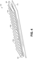
- the components 400 include chip tub components 106a, 106b, and 106c, spacer components 403 and 406, RFID antenna 409, a base 412, and potentially other components.
- the chip tube components 106a-c can be assembled together to span the fixed width of the chip tray 103.
- the spacer components 403 and 406 can be used to fill in any remaining space to span the entire fixed width.
- the width of each chip tube component 106 can be based on a size of gaming chips to be stored in each chip tube and a number of chip tubes.
- the span of the assembled chip tube components 106 may not be set precisely to fit within a fixed span of the chip tray 103. As such, a gap may exists between the sides of the chip tray 103 and chip tube components 106.
- the spacer components 403 and 406 can be coupled to the sides of the chip tube components 106 to facilitate a precise fit.
- One or more RFID antenna 409 can be placed underneath the chip tube components 106.
- the RFID antenna 409 is installed into the gaming table 100 below a base 412 of an enclosure for the chip tray 103.
- the RFID antenna 409 can be covered to protect the RFID antenna 409 from damage when the chip tray 103 is inserted into the gaming table 100.
- the RFID antenna 409 can be locked into the gaming table 100 for security reasons to prevent tampering.
- the RFID antenna 409 can be configured to read gaming chips placed in the chip tube components 106 via the gaming service 227 ( FIG. 2 ).
- a result of the read can be displayed to the dealer on a display to show a quantity and amount of gaming chips in the chip tray 103.
- the display can also include an authentication result to indicate whether all of the read gaming chips successfully authenticated or not.
- the display can include one or more indicators on the table, such as, for example, LED indicators, that indicate a success or failure of a read or validation.
- the chip tray 103 can include shielding when one or more RFID antennas are used.
- the components 500 include chip tub components 106d, 106e, and 106f, spacer components 403 and 406, and potentially other components.
- the chip tube components 106 can have a coupling edge on a first side and a second side opposite the first side.
- the coupling edges can be configured to mate against one another at a joint 503. In some embodiments, the coupling edges can prevent disconnecting adjacent chip tube components 106 unless the chip tube components 106 and slide in opposite directions along the coupling edge with respect to one another.
- the coupling edges shown correspond to a hooking mechanism, in other embodiments, other types of edge joints can be used such as a tongue and grove joint, finger joints, or other types of edge joints.
- the spacer components 403 and 406 can also include a coupling edge to edge join with the adjacent chip tube components 106.
- the chip tube component 106 can include one or more tubes 303a-303c.
- the chip tube component 106 can have a first coupling edge 603 and a second coupling edge 606 opposite the first coupling edge.
- the front edge 609 and/or a back edge can have a coupling edge to couple to a front and back spacer component, similar to spacer components 403 and 406.
- the chip tube component 106 can be created using a 3D printer or any other manufacturing process for plastic and metal materials. As an example, material removal or machining can be used to form chip tube components 106.
- the chip tube components 106 can also be formed or injection molded.
- a catalogue of chip tube components 106 can be provided to a casino operator to facilitate configuration of each chip tray 103.
- RFID When RFID is being utilized, one or more RFID antennas and potentially a shielding plate can be placed underneath the chip tube components 106. The RFID antenna and shielding can be made to cover a complete width off the tray regardless of the configuration of the chip tube components 106.
- a chip tube component 106 can include one or more gaming chip storage row 303d.
- the gaming chip storage row 303d can hold one or more rectangular plaque in a space 703.
- the edges 706 can provide horizontal support for the plaques while also providing space for fingers to reach in and grab plaques.
- FIG. 8 an example hardware diagram of a computing device 800 is illustrated.
- the gaming service 227 may be implemented, in part, using one or more elements of the computing device 800.
- the computing device 800 can include one or more of a processor 810, a Random Access Memory (“RAM”) 820, a Read Only Memory (“ROM”) 830, a memory device 840, a network interface 850, and an Input Output (“I/O") interface 860.
- the elements of the computing device 800 are communicatively coupled via a bus 802.
- the processor 810 can include an arithmetic processor, Application Specific Integrated Circuit ("ASIC"), or other types of hardware or software processors.
- the RAM and ROM 820 and 830 can include a memory that stores computer-readable instructions to be executed by the processor 810.
- the memory device 830 stores computer-readable instructions thereon that, when executed by the processor 810, direct the processor 810 to execute various aspects of the present disclosure described herein.
- the processor 810 includes an ASIC
- the processes described herein may be executed by the ASIC according to an embedded circuitry design of the ASIC, by firmware of the ASIC, or both an embedded circuitry design and firmware of the ASIC.
- the memory device 830 comprises one or more of an optical disc, a magnetic disc, a semiconductor memory (i.e., a semiconductor, floating gate, or similar flash based memory), a magnetic tape memory, a removable memory, combinations thereof, or any other known memory means for storing computer-readable instructions.
- the network interface 850 can include hardware interfaces to communicate over data networks.
- the I/O interface 860 can include device input and output interfaces such as keyboard, pointing device, display, communication, and other interfaces.
- the bus 802 can electrically and communicatively couple the processor 810, the RAM 820, the ROM 830, the memory device 840, the network interface 850, and the I/O interface 860, so that data and instructions may be communicated among them.
- the processor 810 is configured to retrieve computer-readable instructions stored on the memory device 840, the RAM 820, the ROM 830, or another storage means, and copy the computer-readable instructions to the RAM 820 or the ROM 830 for execution, for example.
- the processor 810 is further configured to execute the computer-readable instructions to implement various aspects and features of the present disclosure.
- the processor 810 may be adapted and configured to execute the processes described above with reference to FIG. 2 , including the processes described as being performed by the gaming service 227.
- the memory device 840 may store the data stored in the database 215.
- Fig. 9 is a perspective view of a chip tray 104 according to a second embodiment.
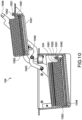
- the chip tray 104 is a dual chip tray constructed by an upper tray 1041 and a lower tray 1042.
- Fig. 10 is a cross sectional view of the chip tray 104 in a state where the lower tray 1042 is opened
- Fig. 11 is a cross sectional view of the chip tray 104 in a state where the upper tray 1041 is contained in the lower tray 1042.
- the lower stage chip tray 1042 has a rectangular parallelepiped shape which is opened in its upper surface, and chip tube components 106 are arranged side by side in a bottom surface of an internal portion thereof.
- the upper stage chip tray 1041 has a tray shape, and the chip tube components 106 are arranged side by side in a bottom surface of an internal portion thereof.
- the upper tray 1041 can be stored in the lower tray 1042 from the above of the chips stored in the lower tray 1042.
- the upper tray 1041 is movably connected to the lower tray 1042 via a link mechanism 1043. By lifting up a handle 1044, the upper tray 1041 can be moved upward diagonally from the lower tray 1042 while keeping a posture of the upper tray 1041, thereby making an upper surface of the lower tray 1042 open.
- a bottom surface of the upper tray 1041 is provided with an RFID antenna for reading an RFID tag which is embedded in the gaming chip stored in the upper tray 1041
- a bottom surface of the lower tray 1042 is also provided with an RFID antenna for reading an RFID tag which is embedded in the gaming chip stored in the lower tray 1042.
- a shield blocking an electromagnetic wave from the RFID antenna or a jamming antenna generating an electromagnetic wave for partly cancelling or weakening the electromagnetic wave from the RFID antenna may be used so as to prevent the RFID antenna of the upper tray 1041 from reading the RFID tag of the gaming chip stored in the lower tray 1042, or prevent the RFID antenna of the lower tray 1042 from reading the RFID tag of the gaming chip stored in the upper tray 1041.
- Fig. 12 is a perspective view of a chip tube component (for small circular chips) according to the present embodiment
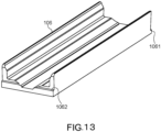
- Fig. 13 is a perspective view of a chip tube component (for large circular chips) according to the present embodiment
- Fig. 14 is a perspective view of a chip tube component (for plaques) according to the present embodiment.
- Each of the chip tube components is constructed by a single gaming chip storage row.
- the chip tube components 106 for the small circular chip, for the large circular chip and for the plaque are respectively different in their widths in correspondence to sizes of the gaming chips to be stored therein.
- a side surface of each of the chip tube components 106 is a flat surface, the surfaces are in contact with each other when the chip tube components 106 are coupled, and a gap is not formed between the side surfaces.
- the chip tube components 106 do not have a structure in which the adjacent chip tube components 106 lap over each other in the coupled portion vertically when the adjacent chip tube components 106 are coupled to each other at right edges and left edges, the respective chip tube components 106 can be independently attached to and detached from the upper tray 1041 or the lower tray 1042 separately from the other chip tube components 106 by detaching a securing L-shaped angle 1051 mentioned later.
- the chip tube component 106 is arranged in a slightly inclined manner so that a front end comes to an upper side and a rear end comes to a lower side. Further, the chip tube component 106 for the upper tray 1041 is formed to be shorter in a longitudinal direction than the chip tube component for the lower tray 1042.
- Holding flanges 1061 and 1062 are formed respectively at the front end and the rear end of the chip tube component 106 in the longitudinal direction.
- the flanges 1062 at the rear end are fitted to locking grooves 1045 and 1046 which are respectively formed in the upper tray 1041 and the lower tray 1042.
- the front end of the chip tube component 106 is secured to the upper tray 1041 and the upper tray 1042 by the securing L-shaped angle 105 holding the flange 1061 at the front end from the above.
- the securing L-shaped angle 1051 is secured to the upper tray 1041 and the lower tray 1042 respectively by screws 1052.
- the front end and the rear end of the chip tube component 106 are opened.
- the chip tube component 106 When the chip tube component 106 is installed in the upper tray 1041 or the lower tray 1042, the upper tray 1041 and the lower tray 1042 support the flat surface of the gaming chip in a direction of tilt.
- Fig. 15 is a perspective view of a chip tray 108 according to a third embodiment.
- the chip tray 108 according to the present embodiment is also a dual chip tray including an upper tray 1081 and a lower tray 1082 in the same manner as the second embodiment.
- the chip tray 108 is further provided with a collected chip tube component 107.
- the collected chip tube component 107 is one kind of the chip tube component 106, and has a plurality of (two) tubes 303.
- the collected chip tube component 107 is a tray for temporarily reserving the chip collected from a player losing a game.
- Fig. 16 is a cross sectional view of the chip tray 108. As shown in Fig. 16 , the collected chip tube component 107 is fitted to the lower tray 1082 so as to come level with the upper tray 1081 contained in the lower tray 1082. A space is provided below the collected chip tube component 107, and a camera (not shown) is arranged in the space.
- spacer components 407 are provided at both ends of the chip tube component 106 in the lower tray 1041 in an array direction.
- the chip tube components 106 for the circular gaming chips and the chip tube components 106 for the plaque which are different from each other in their widths can be arranged in the lower tray 1081 by being combined at optional numbers.
- the chip tube components 106 for the circular gaming chips and the chip tube components 106 for the plaques can be similarly used by being combined at optional numbers.
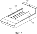
- Fig. 17 is a perspective view of the collected chip tube component 107
- Fig. 18 is a cross sectional view of the collected chip tube component 107.
- a slit 1071 is formed in each of the tubes 303 of the collected chip tube component 107 in a tube longitudinal direction (that is, a stacking direction of the gaming chips).
- a camera arranged below the collected chip tube component 107 shoots a side surface of the gaming chip exposed from the slit 1071.
- a plurality of mirrors are installed between the camera and the slit 1071, and an illuminating light illuminating the slit 1071 is also provided. The plurality of mirrors conduct the reflected light from the slit 1071 illuminated by the illumination to a lens of the camera.
- the gaming chip used in the present embodiment has a stripe pattern in a thickness direction on its side surface.
- the stripe pattern is formed by sandwiching a given color layer by common color layers.
- the given color is set per denomination (value) of the gaming chip. More specifically, a color of the given color layer expresses the denomination of the gaming chip.
- the common color is used in common for the chips having difference denominations. According to the structure mentioned above, when stacking the gaming chips, the given color layers for discriminating the denomination are not adj acent each other, and denomination of the gaming chips can be discriminated every one gaming chip.
- a computing device 800 specifies the denomination in each of the gaming chips which are stored in the collected chip tube component 107, by making an image analysis to the shooting image of the camera.
- the RFID antenna may be provided in the collected chip tube component 107, and the RFID tags of the gaming chips stored in the collected chip tube component 107 may be read by the RFID antenna.
- the computing device 800 may make an inspection of the gaming chips stored in the collected chip tube component 107 by comparing the denomination acquired from the shooting image of the camera and the denomination acquired by reading the RFID tag.
- Fig. 19 is a perspective view of a chip tube component (for circular gaming chips) according to the present embodiment
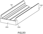
- Fig. 20 is a perspective view of a chip tube component (for plaques) according to the present embodiment.
- Each of the chip tube components is constructed by a single gaming chip storage row.
- the chip tube components 106 for the small circular chip and for the plaque are different in their widths in correspondence to the size of the gaming chip.
- the chip tube component 106 is open in its front end, but has in its rear end a rear end wall 1063 which supports the gaming chip. As a result, the gaming chips can be stably retained in the chip tube component 106 even when the chip tube component 106 is detached from the upper tray 1081 or the lower tray 1082 while storing the gaming chips in the chip tube component 106.
- Fig. 21 is a perspective view of a spacer component according to the present embodiment.
- Flanges 4071 and 4072 are formed at a front end and a rear end of the spacer component 407 in the same manner as the chip tube component 106.
- the spacer component 407 is also secured to the upper tray 1081 or the lower tray 1082 by an L-shaped angle 1081 (refer to Fig. 15 ) in the same manner as the chip tube component 106.
- An example of one spacer component 407 is illustrated in Fig. 20 , however, plural kinds of spacer components 407 having different widths may be prepared and may be used in correspondence to the kind and the number of the used chip tube components 106.
- the camera installed under the collected chip tube component 107 may be a visible light camera or an infrared camera used for detecting only the number of the gaming chips in the collected chip tube component 107.
- the camera may be not installed, and the collected chips may be detected independently from the other chips in chip tube component 106 only by RFID.
- an RFID antenna may be provided only on the bottom surface of the upper tray 1041.
- the RFID antenna may read both the RFID tags embedded in the circular gaming chips or plaques stored in the upper tray 1041 and the RFID tags embedded in the circular gaming chips or plaques stored in the lower tray 1042.
- the RFID tags in the upper tray 1041 and the lower tray 1042 may be read by the single RFID antenna, and when the upper tray 1041 is out of the lower tray 1042, the RFID tags in the upper tray 1041 may be read by the single RFID antenna.
- the upper antenna may read only the gaming chips in the upper tray 1041
- the lower antenna may read the gaming chips in the lower tray 1042 and a part or all of the gaming chips in the upper tray 1041
- the upper antenna may read a part or all of the gaming chips in the upper tray 1041
- the lower antenna may read only the gaming chips in the lower tray 1042.
Landscapes
- Physics & Mathematics (AREA)
- General Physics & Mathematics (AREA)
- Engineering & Computer Science (AREA)
- Multimedia (AREA)
- Educational Technology (AREA)
- Slot Machines And Peripheral Devices (AREA)
- Pinball Game Machines (AREA)
- Packaging Frangible Articles (AREA)
- Packaging Of Annular Or Rod-Shaped Articles, Wearing Apparel, Cassettes, Or The Like (AREA)
- Management, Administration, Business Operations System, And Electronic Commerce (AREA)
- Preparing Plates And Mask In Photomechanical Process (AREA)
- Container, Conveyance, Adherence, Positioning, Of Wafer (AREA)
- Packages (AREA)
- Credit Cards Or The Like (AREA)
- Details Of Rigid Or Semi-Rigid Containers (AREA)
Description
- The present disclosure relates to a new system having a gaming chip storage row for storing gaming chips, a chip tray and a method.
- A chip tray can be used to store gaming chips for a dealer of a wagering game. The chip tray can store different denominations of gaming chips in a safe place. Chip trays can be made from various materials including plastic and metal.
- During the last 2 decades, the casino industry has been using the RFID technology to protect and track their currency products also called plaques and chips which are token that have a face value to allow gambling, payouts. The RFID tags provide a unique identifier to each item and also typically include a ROM memory to store the specific information of the currency product. The chips are stored in some trays at the gaming tables. For big gambling games such as Baccarat, the Casino use dual level chip trays. Using RFID in the tags gives the possibility for the Casino to have live inventory of these floats. The opening systems of these dual level floats is generally based on 2 handles and no assistance making it difficult to open when the float has many chips (up to 2000).
WO 2012/058401 A2 discloses a dual chip tray that has a lower housing assembly having an interior configured for receiving at least one removable chip tray for holding gaming currency. A top tray sub assembly is hinged relative to the lower housing assembly to pivot between a closed position and an open position. A chip tray lid is provided to cover the lower housing assembly in a covered position. RFID antennas may be positioned within the lower housing assembly and the top tray sub assembly.EP 3 324 374 A1 discloses a chip case capable of containing a row of gaming chips stacked in a thickness direction, and an inspection system that includes a reading device that reads the radio tag of the gaming chip in the case and acquires gaming chip information of the gaming chip, and a determining unit that compares the gaming chip information with a maximum of the number of gaming chips storable in the case.EP 2 595 093 A2 discloses a casino chip tray where RFID tag-embedded casino chips can be accommodated, the tray having a housing of which an upper side can be opened in order for the casino chip tray to be located, with an RFID antenna line which is arranged on the circumference and on the bottom side of the housing, and with an RFID reader that is connected to the RFID antenna line. - The present disclosure aims at providing a system changing an amount of storage for various kinds of gaming chips, a chip tray and a method.
- An aspect of the present disclosure is a system including a first chip tube component comprising at least one first gaming chip storage row corresponding to a first size of gaming chip; and a second chip tube component corresponding to a second size of gaming chip, wherein a first edge of the first chip tube component is coupled to a second edge of the second chip tube component.
- An aspect of the present disclosure is a chip tray comprising: a first chip tube component comprising at least one first gaming chip storage row corresponding to a first size of gaming chip; and a second chip tube component comprising at least one second gaming chip storage row corresponding to a second size of gaming chip, wherein a first edge of the first chip tube component is coupled to a second edge of the second chip tube component.
- An aspect of the present disclosure is a method comprising, coupling a first chip tube component to a second chip tube component; coupling a third chip tube component to the second chip tube component to form a plurality of coupled chip components; and positioning the plurality of coupled chip components in an enclosure.
- With 2 handles, the opening is not synchronized. The invention consists in installing a mechanism to help the upper tray open in a guided way and assist the opening of the tray without creating a risk of maintenance issues.
- The mechanism is based on 3 principles:
- A single bar that links the left and the right of a tray to open. The important part is to have a system linking the left side to the right side to have a guided opening.
- A lever system to reduce the efforts when opening
- A spring linked to the lever system to help the beginning of the movement when opening and closing the tray.
- Such a system gives the possibility to open the tray with one hand while the second hand picks a chip from the bottom tray. This feature saves time to the Dealer while keeping the high denomination chips in a protected area in the bottom tray.
- The invention can also give the possibility to have several compartments in the tray and therefore to open only parts of the upper tray. This way, the access to some compartments can also be blocked by access control devices.
- Integrating sensors gives the possibility to have software control of the opening, the traceability and securing the content of the float.
- For a more complete understanding of the embodiments and the advantages thereof, reference is now made to the following description, in conjunction with the accompanying figures briefly described as follows:
-
FIG. 1 is a drawing of a gaming table according to various example embodiments. -
FIG. 2 is a drawing of a networked environment according to various example embodiments. -
FIG. 3 is a chip tray according to various example embodiments. -
FIG. 4 illustrates an exploded view of components of a chip tray according to various embodiments of the present disclosure. -
FIG. 5 illustrates an exploded view of components of a chip tray according to various embodiments of the present disclosure. -
FIG. 6 illustrates a chip tube component according to various embodiments of the present disclosure. -
FIG. 7 illustrates a portion of a gaming chip storage row according to various embodiments of the present disclosure. -
FIG. 8 is a schematic block diagram that illustrates an example computing device employed in the networked environment ofFIG. 2 according to various embodiments. -
Fig. 9 is a perspective view of a chip tray according to a second embodiment. -
Fig. 10 is a cross sectional view of achip tray 104 according to the second embodiment in a state where the lower tray is opened. -
Fig. 11 is a cross sectional view of the chip tray according to the second embodiment in a state where an upper tray is contained in a lower tray. -
Fig. 12 is a perspective view of a chip tube component (for a small circular chip) according to the second embodiment. -
Fig. 13 is a perspective view of a chip tube component (for a large circular chip) according to the second embodiment. -
Fig. 14 is a perspective view of a chip tube component (for a plaque) according to the second embodiment. -
Fig. 15 is a perspective view of a chip tray according to a third embodiment. -
Fig. 16 is a cross sectional view of the chip tray according to the third embodiment. -
Fig. 17 is a perspective view of a collected chip tube component according to the third embodiment. -
Fig. 18 is a cross sectional view of the collected chip tube component according to the third embodiment. -
Fig. 19 is a perspective view of a chip tube component (for a gaming chip) according to the third embodiment. -
Fig. 20 is a perspective view of a chip tube component (for a plaque) according to the third embodiment. -
Fig. 21 is a perspective view of a spacer component according to the third embodiment. - The drawings illustrate only example embodiments and are therefore not to be considered limiting of the scope described herein, as other equally effective embodiments are within the scope and spirit of this disclosure. The elements and features shown in the drawings are not necessarily drawn to scale, emphasis instead being placed upon clearly illustrating the principles of the embodiments. Additionally, certain dimensions may be exaggerated to help visually convey certain principles. In the drawings, similar reference numerals between figures designate like or corresponding, but not necessarily the same, elements.
- In the following paragraphs, the embodiments are described in further detail by way of example with reference to the attached drawings. In the description, well known components, methods, and/or processing techniques are omitted or briefly described so as not to obscure the embodiments. As used herein, the "present disclosure" refers to any one of the embodiments described herein and any equivalents. Furthermore, reference to various feature(s) of the "present embodiment" is not to suggest that all embodiments must include the referenced feature(s).
- Among embodiments, some aspects of the present disclosure are implemented by a computer program executed by one or more processors, as described and illustrated. As would be apparent to one having ordinary skill in the art, one or more embodiments may be implemented, at least in part, by computer-readable instructions in various forms, and the present disclosure is not intended to be limiting to a particular set or sequence of instructions executed by the processor.
- The embodiments described herein are not limited in application to the details set forth in the following description or illustrated in the drawings. The disclosed subject matter is capable of other embodiments and of being practiced or carried out in various ways. Also, the phraseology and terminology used herein is for the purpose of description and should not be regarded as limiting. The use of "including," "comprising," or "having" and variations thereof herein is meant to encompass the items listed thereafter, additional items, and equivalents thereof. The terms "connected" and "coupled" are used broadly and encompass both direct and indirect connections and couplings. In addition, the terms "connected" and "coupled" are not limited to electrical, physical, or mechanical connections or couplings. As used herein the terms "machine," "computer," "server," and "work station" are not limited to a device with a single processor, but may encompass multiple devices (e.g., computers) linked in a system, devices with multiple processors, special purpose devices, devices with various peripherals and input and output devices, software acting as a computer or server, and combinations of the above.
- The term gaming chips, as used herein, can include any chip, plaque, jeton, or other gaming currency that may be used in a casino, gaming room, or digital game. Each gaming chip can represent a value that is predetermined or not. The gaming chips can be made from a rigid plastic material or clay to obtain a structure that is solid enough to resist conditions of use in casinos. The gaming chips can be used throughout a casino. For example, at gaming tables, gaming chips can be received for play or the conclusion of a game or hand, cash can be received and gaming chips paid out (buy-in), and gaming chips may be paid out during play. In a cashier area, gaming chips can be received and cash can be paid out (cash out). Alternatively, cash can be received and gaming chips can be paid out (buy-in).
- <First Embodiment> Turning now to the drawings, exemplary embodiments are described in detail. With reference to
FIG. 1 , shown is a gaming table 100 according to various embodiments of the present disclosure. The gaming table 100 includes achip tray 103 among other components. Thechip tray 103 can include one or morechip tube components 106, such as, for example,chip tube components chip tray 103 can include alockable lid 109. - The
chip tray 103 can be covered by alid 109 that can be locked to limit access to thechip tray 103. When a wagering game is active, thelid 109 can be completely removed. Similarly, when the gaming table is open, thelid 109 can be unlocked so that an employee can lift it if desirable. When the wagering game is closed, thelid 109 can be locked. - With reference to
FIG. 2 , shown is anetworked environment 103 according to various embodiments. Thenetworked environment 103 includes acomputing environment 203, one or moregaming table devices 206 positioned in one or more gaming tables 100, and one ormore cameras 209, which are in data communication with each other via anetwork 212. Thenetwork 212 includes, for example, the Internet, intranets, extranets, wide area networks (WANs), local area networks (LANs), wired networks, wireless networks, or other suitable networks, etc., or any combination of two or more such networks. For example, such networks may comprise satellite networks, cable networks, Ethernet networks, and other types of networks. - The
computing environment 203 can include, for example, a server computer or any other system providing computing capability. Alternatively, thecomputing environment 203 may employ a plurality of computing devices that may be arranged, for example, in one or more server banks or computer banks or other arrangements. Such computing devices may be located in a single installation or may be distributed among many different geographical locations. For example, thecomputing environment 203 may include a plurality of computing devices that together may comprise a hosted computing resource, a grid computing resource, and/or any other distributed computing arrangement. In some cases, thecomputing environment 203 may correspond to an elastic computing resource where the allotted capacity of processing, network, storage, or other computing-related resources may vary over time. - Various applications and/or other functionality may be executed in the
computing environment 203 according to various embodiments. Also, various data is stored in adata store 215 that is accessible to thecomputing environment 203. Thedata store 215 may be representative of a plurality ofdata stores 215 as can be appreciated. The data stored in thedata store 215, for example, is associated with the operation of the various applications and/or functional entities described below. Thedata store 215 can includecurrency data 218 andgaming data 221, among other data. - The components executed on the
computing environment 203, for example, include agaming service 227, and other applications, services, processes, systems, engines, or functionality not discussed in detail herein. Thegaming service 227 is executed to recognize gaming chips used on one or more tables 206. As an example, a stack of gaming chips can be positioned in various locations on a gaming table 100 during a wagering game. One or more images can be captured of the gaming table 100 and thegaming service 227 can identify locate the one or more stacks of gaming chips in the images, count the gaming chips in each stack, and evaluate denominations for the gaming chips. It can be appreciated that some or all of the functionality as described with reference to thegaming service 227 can be executed in agaming table device 206 including a computing device at the gaming table 100. - The
currency data 218 can include a list of all active gaming chips including any identifiers associated with the gaming chips, such as, for example, RFID tag identifiers, barcode identifiers, visual characteristics including color information, and other identifiers. Thegaming data 221 can store a history of sensor inputs received as well as any configuration, calibration, and control settings. - The gaming table 100 is representative of a plurality of gaming tables that may be coupled to the
network 212. Thegaming table device 206 can include, for example, one or more computing devices with a processor-based system such as a computer system. Such a computer system may be embodied in the form of an embedded computing device or other devices with like capability. The gaming table 100 can include one ormore cameras 230, one ormore sensors 233, achip tray 103, one ormore bet spots 239, achip recycler 242, and abill validator 245. - Similar to
cameras 209, thecameras 230 can capture images of a surface of the gaming table 100. Thegaming table device 206 orcameras 230 can send the images to thegaming service 227 via thenetwork 212. The images can be sent to thegaming service 227 as a video stream of the surface of the gaming table 100. Thegaming service 227 can receive images from various angles fromcameras sensors 233 can include RFID antennas, video barcode scanners, weigh scales, and other sensors. The sensors 133 can be used to identify gaming chips played on a gaming table. - The
gaming service 227 can validate RFID currency based on information read fromsensors 233 that are RFID antennas. An RFID antenna can be positioned at thechip tray 103, at each of the bet spots 239, at thechip recycler 242, and in another positions. Thegaming table device 206 can read RFID tags from RFID-enabled gaming chips using the RFID antennas. The information from the RFID tags can be stored along with data related to RFID antenna read the RFID tag. For example, an identifier from one or more RFID-enabled gaming chip can be read by an RFID antenna at aparticular bet spot 239. - With reference to
FIG. 3 , shown is achip tray 103 according to various embodiments of the present disclosure. Thechip tray 103 can include a storage rack to store gaming chips. Thechip tray 103 can be placed in a gaming table to keep casino gaming chips secure. Thechip tray 103 can be used by an employee, such as a dealer or manager. - The gaming chips can have different shapes and sizes for different reasons. As an example, a size and shape of gaming chips can vary based on denomination. A category of a population the gaming chips are targeted toward can influence the size and shape. For example, gaming chips targeted toward a mass market, very important persons (VIP), premium, or other categories can have varied sizes and shapes.
- Casino operators can have a preference on the layout of a
chip tray 103 used. The preference can depend on a variety of factors including on the casino history and on the area. Most casinos adapt or customize thechip tray 103 according to the wagering game and the currency needs of the precise location. With injection moldedchip trays 103, if those customizations involve changing a layout of the storage area in thechip tray 103, a new injection mold may be necessary which can drastically increase the cost of production. - For a casino, it can be important to know a current amount and quantity of gaming chips in the
chip tray 103 in order to manage the turnover of the gaming tables, the fills and credits at the gaming table, and the opening and closing of gaming tables, among other aspects. A casino operator can check the number of gaming chips visually. However, this can be impractical and time consuming. In other instances, the casino operator can use RFID chip trays when RFID enabled chips and plaques are utilized. - For
chip trays 103, RFID equipped or not, the needed customization, which can involve the number of rows and the configuration of each row, can involve new designs and specific manufacturing tools like molds to accommodate the customized design. The customized configuration can involve defining the overall capacity of the chip tray, defining the diameter of the gaming chips being stored in the different rows, and defining the shape of the gaming chips, among other configurations. The shape of the gaming chip can be rectangular if a casino operator wants to store rectangular plaques that may be larger. - Casino operators may store higher denominations in the middle rows of the
chip tray 103 and the smaller denominations in the external rows of thechip tray 103. The gaming chips with higher denominations can have larger diameters, such as 45 millimeters (mm) or 48 mm. The gaming chips with lower denominations can have smaller diameter, such as 39 mm or 40 mm. The variance in diameters can be helpful to differentiate the gaming chips when the gaming chips are stack together to prevent mistakes. - A changeable configuration of
chip tube components 106 can be used in order to facilitate the customization of thechip trays 103. The chip tube component system can reduce the design and tooling costs and also to offer a solution to change the configuration of a tray on a group of tables easily and in a short time. Thechip tray 103 is developed to be scalable and modular. In some embodiments, thechip tray 103 is RFID compatible. - The
chip tray 103 can have a fixed width. A fixed sized of enclosure can also be used. In some embodiments, a set of fixed widths and fixed sized enclosures can be used to enable larger andsmaller chip trays 103 based on preference. Thechip tray 103 can be assembled withchip tube components 106 which can includetubes 303. Each of thetubes 303 can be configured to hold a specific shape and size of gaming chip, which can include, for example, round, rectangular, or other shape of gaming chip. - The
chip tray 103 can include a base structure 306 to provide support for thechip tube components 106 and a trim cover 309. In some embodiments, the trim cover 309 can be detachably coupled to the base structure 306 to affix thechip tube components 106 in place. As an example, tabs on the trim cover 309 can click into slots on the base structure 306 to hold the trim cover 309 in place. The trim cover 309 can cover an outer edge of thechip tube components 106 to hold thechip tube components 106 in place. - The
chip tube components 106 can have one ormore tubes 303, with eachtube 303 being referred to as a gaming chip storage row. The casino operator can assemble thechip tube components 106 to fill in the available space. The chip tray can be customized based on the current needs of the casino. In some embodiments, the weight of gaming chips can be used to secure thechip tube components 106 in place. An edge of thechip tube components 106 can be coupled together to secure thechip tube components 106 in place. In some embodiments, the edges of adjacentchip tube components 106 can be locked together based on a shape of the edges. - In one example embodiment, the
chip tube components 106 each have two to three gamingchip storage rows 303, and thechip tray 100 can have a total of twelve to sixteen gamingchip storage rows 303 by assembling more than onechip tube component 106. The gaming chip storage rows can be configured to hold round gaming chips of 35 mm, 40 mm, 41 mm, 45 mm, or another diameter size. The gaming chip storage rows can be configured to hold rectangular gaming chips of 85 mm or other sizes. Different gaming tables 100 on a casino floor can each have different configurations ofchip tube components 106 on arespective chip tray 103. Further, thechip tray 103 for each gaming table 100 can be quickly and easily changed to accommodate differentchip tube components 106. - With reference to
FIG. 4 , shown is an exploded view ofselect components 400 of anexample chip tray 103 according to various embodiments of the present disclosure. Thecomponents 400 includechip tub components spacer components RFID antenna 409, abase 412, and potentially other components. - The
chip tube components 106a-c can be assembled together to span the fixed width of thechip tray 103. Thespacer components chip tube component 106 can be based on a size of gaming chips to be stored in each chip tube and a number of chip tubes. In various embodiments, because variouschip tube components 106 of various fixed sizes are selectable, the span of the assembledchip tube components 106 may not be set precisely to fit within a fixed span of thechip tray 103. As such, a gap may exists between the sides of thechip tray 103 andchip tube components 106. Thespacer components chip tube components 106 to facilitate a precise fit. - One or
more RFID antenna 409 can be placed underneath thechip tube components 106. In some embodiments, theRFID antenna 409 is installed into the gaming table 100 below abase 412 of an enclosure for thechip tray 103. TheRFID antenna 409 can be covered to protect theRFID antenna 409 from damage when thechip tray 103 is inserted into the gaming table 100. TheRFID antenna 409 can be locked into the gaming table 100 for security reasons to prevent tampering. - The
RFID antenna 409 can be configured to read gaming chips placed in thechip tube components 106 via the gaming service 227 (FIG. 2 ). A result of the read can be displayed to the dealer on a display to show a quantity and amount of gaming chips in thechip tray 103. The display can also include an authentication result to indicate whether all of the read gaming chips successfully authenticated or not. In some embodiments, the display can include one or more indicators on the table, such as, for example, LED indicators, that indicate a success or failure of a read or validation. In some embodiments, thechip tray 103 can include shielding when one or more RFID antennas are used. - With reference to
FIG. 5 , shown is an exploded view of select components 500 of anexample chip tray 103 according to various embodiments of the present disclosure. The components 500 includechip tub components spacer components chip tube components 106 can have a coupling edge on a first side and a second side opposite the first side. The coupling edges can be configured to mate against one another at a joint 503. In some embodiments, the coupling edges can prevent disconnecting adjacentchip tube components 106 unless thechip tube components 106 and slide in opposite directions along the coupling edge with respect to one another. Although the coupling edges shown correspond to a hooking mechanism, in other embodiments, other types of edge joints can be used such as a tongue and grove joint, finger joints, or other types of edge joints. As shown, thespacer components chip tube components 106. - With reference to
FIG. 6 , shown is an examplechip tube component 106 according to various embodiments of the present disclosure. Thechip tube component 106 can include one ormore tubes 303a-303c. Thechip tube component 106 can have afirst coupling edge 603 and asecond coupling edge 606 opposite the first coupling edge. In some embodiments, thefront edge 609 and/or a back edge (not shown) can have a coupling edge to couple to a front and back spacer component, similar tospacer components - The
chip tube component 106 can be created using a 3D printer or any other manufacturing process for plastic and metal materials. As an example, material removal or machining can be used to formchip tube components 106. Thechip tube components 106 can also be formed or injection molded. - A catalogue of
chip tube components 106 can be provided to a casino operator to facilitate configuration of eachchip tray 103. When RFID is being utilized, one or more RFID antennas and potentially a shielding plate can be placed underneath thechip tube components 106. The RFID antenna and shielding can be made to cover a complete width off the tray regardless of the configuration of thechip tube components 106. - With reference to
FIG. 7 , shown is a top view of aportion 700 of an example gamingchip storage row 303d according to various embodiments of the present disclosure. Achip tube component 106 can include one or more gamingchip storage row 303d. The gamingchip storage row 303d can hold one or more rectangular plaque in aspace 703. Theedges 706 can provide horizontal support for the plaques while also providing space for fingers to reach in and grab plaques. - Turning to
FIG. 8 , an example hardware diagram of acomputing device 800 is illustrated. Thegaming service 227 may be implemented, in part, using one or more elements of thecomputing device 800. Thecomputing device 800 can include one or more of aprocessor 810, a Random Access Memory ("RAM") 820, a Read Only Memory ("ROM") 830, amemory device 840, anetwork interface 850, and an Input Output ("I/O")interface 860. The elements of thecomputing device 800 are communicatively coupled via abus 802. - The
processor 810 can include an arithmetic processor, Application Specific Integrated Circuit ("ASIC"), or other types of hardware or software processors. The RAM andROM processor 810. Thememory device 830 stores computer-readable instructions thereon that, when executed by theprocessor 810, direct theprocessor 810 to execute various aspects of the present disclosure described herein. When theprocessor 810 includes an ASIC, the processes described herein may be executed by the ASIC according to an embedded circuitry design of the ASIC, by firmware of the ASIC, or both an embedded circuitry design and firmware of the ASIC. As a nonlimiting example group, thememory device 830 comprises one or more of an optical disc, a magnetic disc, a semiconductor memory (i.e., a semiconductor, floating gate, or similar flash based memory), a magnetic tape memory, a removable memory, combinations thereof, or any other known memory means for storing computer-readable instructions. Thenetwork interface 850 can include hardware interfaces to communicate over data networks. The I/O interface 860 can include device input and output interfaces such as keyboard, pointing device, display, communication, and other interfaces. Thebus 802 can electrically and communicatively couple theprocessor 810, theRAM 820, theROM 830, thememory device 840, thenetwork interface 850, and the I/O interface 860, so that data and instructions may be communicated among them. - In operation, the
processor 810 is configured to retrieve computer-readable instructions stored on thememory device 840, theRAM 820, theROM 830, or another storage means, and copy the computer-readable instructions to theRAM 820 or theROM 830 for execution, for example. Theprocessor 810 is further configured to execute the computer-readable instructions to implement various aspects and features of the present disclosure. For example, theprocessor 810 may be adapted and configured to execute the processes described above with reference toFIG. 2 , including the processes described as being performed by thegaming service 227. Also, thememory device 840 may store the data stored in thedatabase 215. - <Second Embodiment>
Fig. 9 is a perspective view of achip tray 104 according to a second embodiment. Thechip tray 104 is a dual chip tray constructed by anupper tray 1041 and alower tray 1042.Fig. 10 is a cross sectional view of thechip tray 104 in a state where thelower tray 1042 is opened, andFig. 11 is a cross sectional view of thechip tray 104 in a state where theupper tray 1041 is contained in thelower tray 1042. - The lower
stage chip tray 1042 has a rectangular parallelepiped shape which is opened in its upper surface, andchip tube components 106 are arranged side by side in a bottom surface of an internal portion thereof. The upperstage chip tray 1041 has a tray shape, and thechip tube components 106 are arranged side by side in a bottom surface of an internal portion thereof. Theupper tray 1041 can be stored in thelower tray 1042 from the above of the chips stored in thelower tray 1042. - The
upper tray 1041 is movably connected to thelower tray 1042 via alink mechanism 1043. By lifting up ahandle 1044, theupper tray 1041 can be moved upward diagonally from thelower tray 1042 while keeping a posture of theupper tray 1041, thereby making an upper surface of thelower tray 1042 open. - Although an illustration is omitted, a bottom surface of the
upper tray 1041 is provided with an RFID antenna for reading an RFID tag which is embedded in the gaming chip stored in theupper tray 1041, and a bottom surface of thelower tray 1042 is also provided with an RFID antenna for reading an RFID tag which is embedded in the gaming chip stored in thelower tray 1042. A shield blocking an electromagnetic wave from the RFID antenna or a jamming antenna generating an electromagnetic wave for partly cancelling or weakening the electromagnetic wave from the RFID antenna may be used so as to prevent the RFID antenna of theupper tray 1041 from reading the RFID tag of the gaming chip stored in thelower tray 1042, or prevent the RFID antenna of thelower tray 1042 from reading the RFID tag of the gaming chip stored in theupper tray 1041. -
Fig. 12 is a perspective view of a chip tube component (for small circular chips) according to the present embodiment,Fig. 13 is a perspective view of a chip tube component (for large circular chips) according to the present embodiment, andFig. 14 is a perspective view of a chip tube component (for plaques) according to the present embodiment. Each of the chip tube components is constructed by a single gaming chip storage row. Thechip tube components 106 for the small circular chip, for the large circular chip and for the plaque are respectively different in their widths in correspondence to sizes of the gaming chips to be stored therein. - A side surface of each of the
chip tube components 106 is a flat surface, the surfaces are in contact with each other when thechip tube components 106 are coupled, and a gap is not formed between the side surfaces. As mentioned above, since thechip tube components 106 do not have a structure in which the adjacentchip tube components 106 lap over each other in the coupled portion vertically when the adjacentchip tube components 106 are coupled to each other at right edges and left edges, the respectivechip tube components 106 can be independently attached to and detached from theupper tray 1041 or thelower tray 1042 separately from the otherchip tube components 106 by detaching a securing L-shapedangle 1051 mentioned later. - In each of the
upper tray 1041 and thelower tray 1042, thechip tube component 106 is arranged in a slightly inclined manner so that a front end comes to an upper side and a rear end comes to a lower side. Further, thechip tube component 106 for theupper tray 1041 is formed to be shorter in a longitudinal direction than the chip tube component for thelower tray 1042. -
Holding flanges chip tube component 106 in the longitudinal direction. Theflanges 1062 at the rear end are fitted to lockinggrooves upper tray 1041 and thelower tray 1042. The front end of thechip tube component 106 is secured to theupper tray 1041 and theupper tray 1042 by the securing L-shapedangle 105 holding theflange 1061 at the front end from the above. The securing L-shapedangle 1051 is secured to theupper tray 1041 and thelower tray 1042 respectively byscrews 1052. - The front end and the rear end of the
chip tube component 106 are opened. When thechip tube component 106 is installed in theupper tray 1041 or thelower tray 1042, theupper tray 1041 and thelower tray 1042 support the flat surface of the gaming chip in a direction of tilt. - <Third Embodiment>
Fig. 15 is a perspective view of achip tray 108 according to a third embodiment. Thechip tray 108 according to the present embodiment is also a dual chip tray including anupper tray 1081 and alower tray 1082 in the same manner as the second embodiment. Thechip tray 108 is further provided with a collectedchip tube component 107. The collectedchip tube component 107 is one kind of thechip tube component 106, and has a plurality of (two)tubes 303. The collectedchip tube component 107 is a tray for temporarily reserving the chip collected from a player losing a game. -
Fig. 16 is a cross sectional view of thechip tray 108. As shown inFig. 16 , the collectedchip tube component 107 is fitted to thelower tray 1082 so as to come level with theupper tray 1081 contained in thelower tray 1082. A space is provided below the collectedchip tube component 107, and a camera (not shown) is arranged in the space. - As shown in
Fig. 16 ,spacer components 407 are provided at both ends of thechip tube component 106 in thelower tray 1041 in an array direction. By using thespacer components 407, thechip tube components 106 for the circular gaming chips and thechip tube components 106 for the plaque which are different from each other in their widths can be arranged in thelower tray 1081 by being combined at optional numbers. In theupper tray 1081, by using thespacer components 407, thechip tube components 106 for the circular gaming chips and thechip tube components 106 for the plaques can be similarly used by being combined at optional numbers. -
Fig. 17 is a perspective view of the collectedchip tube component 107, andFig. 18 is a cross sectional view of the collectedchip tube component 107. Aslit 1071 is formed in each of thetubes 303 of the collectedchip tube component 107 in a tube longitudinal direction (that is, a stacking direction of the gaming chips). A camera arranged below the collectedchip tube component 107 shoots a side surface of the gaming chip exposed from theslit 1071. A plurality of mirrors are installed between the camera and theslit 1071, and an illuminating light illuminating theslit 1071 is also provided. The plurality of mirrors conduct the reflected light from theslit 1071 illuminated by the illumination to a lens of the camera. - The gaming chip used in the present embodiment has a stripe pattern in a thickness direction on its side surface. The stripe pattern is formed by sandwiching a given color layer by common color layers. The given color is set per denomination (value) of the gaming chip. More specifically, a color of the given color layer expresses the denomination of the gaming chip. The common color is used in common for the chips having difference denominations. According to the structure mentioned above, when stacking the gaming chips, the given color layers for discriminating the denomination are not adj acent each other, and denomination of the gaming chips can be discriminated every one gaming chip.
- A
computing device 800 specifies the denomination in each of the gaming chips which are stored in the collectedchip tube component 107, by making an image analysis to the shooting image of the camera. The RFID antenna may be provided in the collectedchip tube component 107, and the RFID tags of the gaming chips stored in the collectedchip tube component 107 may be read by the RFID antenna. At this time, thecomputing device 800 may make an inspection of the gaming chips stored in the collectedchip tube component 107 by comparing the denomination acquired from the shooting image of the camera and the denomination acquired by reading the RFID tag. -
Fig. 19 is a perspective view of a chip tube component (for circular gaming chips) according to the present embodiment, andFig. 20 is a perspective view of a chip tube component (for plaques) according to the present embodiment. Each of the chip tube components is constructed by a single gaming chip storage row. Thechip tube components 106 for the small circular chip and for the plaque are different in their widths in correspondence to the size of the gaming chip. - The
chip tube component 106 according to the present embodiment is open in its front end, but has in its rear end arear end wall 1063 which supports the gaming chip. As a result, the gaming chips can be stably retained in thechip tube component 106 even when thechip tube component 106 is detached from theupper tray 1081 or thelower tray 1082 while storing the gaming chips in thechip tube component 106. -
Fig. 21 is a perspective view of a spacer component according to the present embodiment.Flanges spacer component 407 in the same manner as thechip tube component 106. As a result, thespacer component 407 is also secured to theupper tray 1081 or thelower tray 1082 by an L-shaped angle 1081 (refer toFig. 15 ) in the same manner as thechip tube component 106. An example of onespacer component 407 is illustrated inFig. 20 , however, plural kinds ofspacer components 407 having different widths may be prepared and may be used in correspondence to the kind and the number of the usedchip tube components 106. - The camera installed under the collected
chip tube component 107 may be a visible light camera or an infrared camera used for detecting only the number of the gaming chips in the collectedchip tube component 107. - In the case where recognition by a camera installed under the collection
chip tube component 107 is unnecessary, the camera may be not installed, and the collected chips may be detected independently from the other chips inchip tube component 106 only by RFID. - In order to reduce the thickness of the chip tray, an RFID antenna may be provided only on the bottom surface of the
upper tray 1041. In this case, the RFID antenna may read both the RFID tags embedded in the circular gaming chips or plaques stored in theupper tray 1041 and the RFID tags embedded in the circular gaming chips or plaques stored in thelower tray 1042. When theupper tray 1041 is contained in thelower tray 1042, all the RFID tags in theupper tray 1041 and thelower tray 1042 may be read by the single RFID antenna, and when theupper tray 1041 is out of thelower tray 1042, the RFID tags in theupper tray 1041 may be read by the single RFID antenna. In this case, it is preferable to design thelower tray 1042 so that the distance between the RFID tags in the gaming chips and the RFID antenna provided on the bottom surface of theupper tray 1042 is constant. - When the RFID antennas are respectively provided on the bottom surface of the
upper tray 1041 and the bottom surface of thelower tray 1042, the upper antenna may read only the gaming chips in theupper tray 1041, and the lower antenna may read the gaming chips in thelower tray 1042 and a part or all of the gaming chips in theupper tray 1041, or the upper antenna may read a part or all of the gaming chips in theupper tray 1041, and the lower antenna may read only the gaming chips in thelower tray 1042. In any of these, it is possible to determine each of the gaming chips in theupper tray 1041 and the gaming chips in thelower tray 1042 by verifying a collective relationship of the reading results from the upper antenna and the lower antenna. - A phrase, such as "at least one of X, Y, or Z," unless specifically stated otherwise, is to be understood with the context as used in general to present that an item, term, etc., can be either X, Y, or Z, or any combination thereof (e.g., X, Y, and/or Z). Similarly, "at least one of X, Y, and Z," unless specifically stated otherwise, is to be understood to present that an item, term, etc., can be either X, Y, and Z, or any combination thereof (e.g., X, Y, and/or Z). Thus, as used herein, such phrases are not generally intended to, and should not, imply that certain embodiments require at least one of either X, Y, or Z to be present, but not, for example, one X and one Y Further, such phrases should not imply that certain embodiments require each of at least one of X, at least one of Y, and at least one of Z to be present.
- Although embodiments have been described herein in detail, the descriptions are by way of example. The scope of the invention is defined by the appended claims.
Claims (7)
- A dual-chip tray system used in a gaming table and storing gaming chips with a built-in RFID tags, the dual-chip tray comprising:a lower tray (1042) for storing the gaming chips;an upper tray (1041) for storing the gaming chips;wherein the upper tray (1401) is movably connected to the lower chip tray (1042) and moveable between a first position in which the upper tray (1041) is lapped over the lower tray (1042), and a second position in which the upper tray (1041) is displaced from the lower tray (1042) to expose an upper surface of the lower tray (1042); characterized byone or more RFID readers for determining the gaming chips stored in the upper tray (1041)and the lower tray (1042), respectively, by reading the RFID tags of the gaming chips stored in the upper tray (1041) and the lower tray (1042) using at least one RFID antenna.
- The dual-chip tray system according to claim 1,wherein the at least one RFID antenna is one antenna provided on the bottom surface of the upper tray (1041), or the at least one antenna are antennas respectively provided on the bottom surface of the upper tray (1041) and the bottom surface of the lower tray (1042), andwherein the one or more RFID readers read the RFID tags of the plurality of gaming chips stored in the upper tray (1041) and the lower tray (1042) when the upper tray (1041) is lapped over the lower tray (1042) and thereby the lower tray is closed, and read the RFID tags of some of the gaming chips of the plurality of gaming chips when the upper tray (1041) is displaced from the lower tray (1042) and thereby the lower tray (1042) is open.
- The dual-chip tray system according to claim 1, wherein,
the one or more RFID readers use a first antenna to read the RFID tags of the gaming chips stored in the upper tray (1041), and use a second antenna to read the RFID tags of some or all of the gaming chips stored in the upper tray (1041) and the RFID tags of the gaming chips stored in the lower tray (1042), to determine the gaming chips stored in the upper (1041) and lower (1042) trays, respectively. - The dual-chip tray system according to claim 1, wherein,
the one or more RFID readers use a first antenna to read the RFID tags of some or all of the gaming chips stored in the lower tray (1042) and the RFID tags of the gaming chips stored in the upper tray (1041), and use a second antenna to read the RFID tags of the gaming chips stored in the lower tray (1042), to determine the gaming chips stored in the upper tray (1041) and the lower tray (1042), respectively. - The dual-chip tray system according to claim 3 or 4, wherein,
the one or more RFID readers determine the gaming chips stored in the upper tray (1041) and the lower tray (1042), respectively, based on the collective relationship of the reading results of the first antenna and the reading results of the second antenna. - The dual-chip tray system according to claim 1, wherein,
the one or more RFID readers determine the gaming chips stored in the upper tray by reading the RFID tags of the gaming chips stored in the upper tray (1041) using a first antenna, and determines the gaming chips stored in the lower tray (1042) by reading the RFID tags of the gaming chips stored in the lower tray (1042) using a second antenna. - The dual-chip tray system according to any one of claims 3-6, further comprising:
a shield that shields electromagnetic waves from the first antenna and/or the second antenna, and/or a jamming antenna that generates electromagnetic waves to partially cancel or weaken the electromagnetic waves from the first antenna and/or the second antenna so that the first antenna does not read the RFID tags of the gaming chips stored in the lower tray (1042), and/or the second antenna does not read the RFID tags of the gaming chips stored in the upper tray (1041).
Priority Applications (3)
| Application Number | Priority Date | Filing Date | Title |
|---|---|---|---|
| EP25198413.4A EP4632704A3 (en) | 2018-10-09 | 2019-10-09 | SYSTEM, CHIP STORAGE AND PROCEDURES |
| EP24166473.9A EP4372703B1 (en) | 2018-10-09 | 2019-10-09 | System, chip tray, and method |
| EP25183205.1A EP4597463A3 (en) | 2018-10-09 | 2019-10-09 | System, chip tray, and method |
Applications Claiming Priority (2)
| Application Number | Priority Date | Filing Date | Title |
|---|---|---|---|
| US201862743451P | 2018-10-09 | 2018-10-09 | |
| PCT/US2019/055375 WO2020076935A1 (en) | 2018-10-09 | 2019-10-09 | System, chip tray, and method |
Related Child Applications (4)
| Application Number | Title | Priority Date | Filing Date |
|---|---|---|---|
| EP25198413.4A Division EP4632704A3 (en) | 2018-10-09 | 2019-10-09 | SYSTEM, CHIP STORAGE AND PROCEDURES |
| EP25183205.1A Division EP4597463A3 (en) | 2018-10-09 | 2019-10-09 | System, chip tray, and method |
| EP24166473.9A Division EP4372703B1 (en) | 2018-10-09 | 2019-10-09 | System, chip tray, and method |
| EP24166473.9A Division-Into EP4372703B1 (en) | 2018-10-09 | 2019-10-09 | System, chip tray, and method |
Publications (4)
| Publication Number | Publication Date |
|---|---|
| EP3863742A1 EP3863742A1 (en) | 2021-08-18 |
| EP3863742A4 EP3863742A4 (en) | 2022-07-13 |
| EP3863742C0 EP3863742C0 (en) | 2024-05-01 |
| EP3863742B1 true EP3863742B1 (en) | 2024-05-01 |
Family
ID=70164717
Family Applications (4)
| Application Number | Title | Priority Date | Filing Date |
|---|---|---|---|
| EP24166473.9A Active EP4372703B1 (en) | 2018-10-09 | 2019-10-09 | System, chip tray, and method |
| EP25183205.1A Pending EP4597463A3 (en) | 2018-10-09 | 2019-10-09 | System, chip tray, and method |
| EP19870579.0A Active EP3863742B1 (en) | 2018-10-09 | 2019-10-09 | System, chip tray, and method |
| EP25198413.4A Pending EP4632704A3 (en) | 2018-10-09 | 2019-10-09 | SYSTEM, CHIP STORAGE AND PROCEDURES |
Family Applications Before (2)
| Application Number | Title | Priority Date | Filing Date |
|---|---|---|---|
| EP24166473.9A Active EP4372703B1 (en) | 2018-10-09 | 2019-10-09 | System, chip tray, and method |
| EP25183205.1A Pending EP4597463A3 (en) | 2018-10-09 | 2019-10-09 | System, chip tray, and method |
Family Applications After (1)
| Application Number | Title | Priority Date | Filing Date |
|---|---|---|---|
| EP25198413.4A Pending EP4632704A3 (en) | 2018-10-09 | 2019-10-09 | SYSTEM, CHIP STORAGE AND PROCEDURES |
Country Status (11)
| Country | Link |
|---|---|
| US (6) | US11450173B2 (en) |
| EP (4) | EP4372703B1 (en) |
| JP (6) | JP2022504914A (en) |
| KR (4) | KR20250110360A (en) |
| CN (6) | CN118116138A (en) |
| AU (6) | AU2019356918B2 (en) |
| ES (2) | ES2980156T3 (en) |
| MY (1) | MY208914A (en) |
| PH (1) | PH12021550777A1 (en) |
| SG (1) | SG11202103301XA (en) |
| WO (1) | WO2020076935A1 (en) |
Families Citing this family (3)
| Publication number | Priority date | Publication date | Assignee | Title |
|---|---|---|---|---|
| CN114917571A (en) * | 2015-08-03 | 2022-08-19 | 天使集团股份有限公司 | Cheating detection system for recreation ground |
| JP2021175499A (en) * | 2020-04-27 | 2021-11-04 | エンゼルグループ株式会社 | Double chip tray, chip tray, and game management system |
| US12272205B2 (en) * | 2020-08-07 | 2025-04-08 | Angel Group Co., Ltd. | Reading system for game tokens |
Family Cites Families (24)
| Publication number | Priority date | Publication date | Assignee | Title |
|---|---|---|---|---|
| GB723294A (en) * | 1952-12-12 | 1955-02-02 | George Epstein | Improvements in or relating to typewriter desks and the like |
| US5757876A (en) | 1997-02-07 | 1998-05-26 | Cosense, Inc. | Object counter and identification system |
| FR2833102B1 (en) * | 2001-12-03 | 2004-02-27 | Bourgogne Grasset | ELECTRONIC STORAGE DEVICE FOR GAME TOKENS |
| US8616984B2 (en) | 2002-06-12 | 2013-12-31 | Igt | Intelligent player tracking card and wagering token tracking techniques |
| WO2007090267A1 (en) | 2006-02-07 | 2007-08-16 | Ubitrak Inc. | Multi-sensor system for counting and identifying objects in close proximity |
| US9508213B2 (en) | 2010-03-22 | 2016-11-29 | Dominic M. Kotab | Systems and methods of reading gaming chips and other stacked items |
| KR101185963B1 (en) * | 2010-07-12 | 2012-09-26 | 주식회사 에스아이티코리아 | Rfid reader for use in casinochip tray |
| JP5680929B2 (en) * | 2010-10-05 | 2015-03-04 | 株式会社ユニバーサルエンターテインメント | Game table equipment |
| AU2011319851B2 (en) * | 2010-10-27 | 2015-11-05 | Angel Group Co., Ltd. | RFID chip tray |
| PH12013500957A1 (en) * | 2010-10-27 | 2013-07-08 | Gaming Partners Int Usa Inc | Portable reader |
| WO2013177286A1 (en) * | 2012-05-22 | 2013-11-28 | Gaming Partners International Usa, Inc. | Total money management system |
| JP2014095974A (en) | 2012-11-08 | 2014-05-22 | B-Core Inc | Optical automatic recognition code reading method |
| JP5839504B2 (en) * | 2013-04-01 | 2016-01-06 | 株式会社ユニバーサルエンターテインメント | Token storage device |
| US20140339107A1 (en) * | 2013-05-17 | 2014-11-20 | Gaming Partners International Corporation | Rfid plaque box |
| JP6097330B2 (en) * | 2015-04-15 | 2017-03-15 | 株式会社ユニバーサルエンターテインメント | Game media exchange device |
| JP6126637B2 (en) * | 2015-04-15 | 2017-05-10 | 株式会社ユニバーサルエンターテインメント | Game media storage device |
| AU2016265851A1 (en) | 2015-05-15 | 2017-11-02 | Walker Digital Table Systems, Llc | Systems and methods for utilizing RFID technology to facilitate a gaming system |
| KR20240111016A (en) * | 2015-08-03 | 2024-07-16 | 엔제루 구루푸 가부시키가이샤 | Substitute currency for gaming, inspection device, and manufacturing method of substitute currency for gaming, and management system for table games |
| CN114917571A (en) * | 2015-08-03 | 2022-08-19 | 天使集团股份有限公司 | Cheating detection system for recreation ground |
| CN106204918A (en) * | 2016-03-08 | 2016-12-07 | 青岛海尔特种电冰柜有限公司 | Intelligence selling cabinet and intelligence selling system |
| KR20230138054A (en) * | 2016-08-02 | 2023-10-05 | 엔제루 구루푸 가부시키가이샤 | Inspection system and management system |
| MY202267A (en) | 2016-12-30 | 2024-04-21 | Angel Playing Cards Co Ltd | Management system of gaming chips and storage box |
| JP2018130183A (en) * | 2017-02-13 | 2018-08-23 | エンゼルプレイングカード株式会社 | Gaming substitute money tray, table game management system, gaming substitute money tray system, and gaming substitute money management method |
| US9779582B1 (en) * | 2017-04-20 | 2017-10-03 | Igal Shalom Ben Hanan | Smart chip tray assembly and method |
-
2019
- 2019-10-09 MY MYPI2021001762A patent/MY208914A/en unknown
- 2019-10-09 ES ES19870579T patent/ES2980156T3/en active Active
- 2019-10-09 KR KR1020257022542A patent/KR20250110360A/en active Pending
- 2019-10-09 CN CN202311379999.0A patent/CN118116138A/en active Pending
- 2019-10-09 EP EP24166473.9A patent/EP4372703B1/en active Active
- 2019-10-09 EP EP25183205.1A patent/EP4597463A3/en active Pending
- 2019-10-09 EP EP19870579.0A patent/EP3863742B1/en active Active
- 2019-10-09 US US17/283,672 patent/US11450173B2/en active Active
- 2019-10-09 KR KR1020257022543A patent/KR20250109794A/en active Pending
- 2019-10-09 JP JP2021520416A patent/JP2022504914A/en active Pending
- 2019-10-09 CN CN202510983968.9A patent/CN120766402A/en active Pending
- 2019-10-09 KR KR1020217013907A patent/KR102832930B1/en active Active
- 2019-10-09 SG SG11202103301XA patent/SG11202103301XA/en unknown
- 2019-10-09 CN CN202511291686.9A patent/CN121330816A/en active Pending
- 2019-10-09 CN CN201980066523.7A patent/CN114728197A/en active Pending
- 2019-10-09 WO PCT/US2019/055375 patent/WO2020076935A1/en not_active Ceased
- 2019-10-09 CN CN202510064753.7A patent/CN120032459A/en active Pending
- 2019-10-09 CN CN202510983971.0A patent/CN120636048A/en active Pending
- 2019-10-09 ES ES24166473T patent/ES3049166T3/en active Active
- 2019-10-09 KR KR1020237033336A patent/KR102906770B1/en active Active
- 2019-10-09 EP EP25198413.4A patent/EP4632704A3/en active Pending
- 2019-10-09 AU AU2019356918A patent/AU2019356918B2/en active Active
-
2021
- 2021-04-07 PH PH12021550777A patent/PH12021550777A1/en unknown
-
2022
- 2022-07-26 JP JP2022118360A patent/JP2022153530A/en active Pending
- 2022-08-10 US US17/884,811 patent/US11915550B2/en active Active
-
2023
- 2023-09-20 JP JP2023151990A patent/JP7686042B2/en active Active
- 2023-10-16 AU AU2023251385A patent/AU2023251385B2/en active Active
- 2023-10-20 US US18/382,343 patent/US12190677B2/en active Active
-
2024
- 2024-01-16 US US18/413,307 patent/US12272208B2/en active Active
- 2024-04-15 JP JP2024065080A patent/JP2024095809A/en active Pending
- 2024-06-26 JP JP2024102821A patent/JP2024125367A/en active Pending
-
2025
- 2025-02-04 US US19/045,221 patent/US20250182567A1/en active Pending
- 2025-02-18 AU AU2025201130A patent/AU2025201130A1/en active Pending
- 2025-06-30 AU AU2025204984A patent/AU2025204984A1/en active Pending
- 2025-07-29 AU AU2025210748A patent/AU2025210748A1/en active Pending
- 2025-08-25 AU AU2025220881A patent/AU2025220881A1/en active Pending
- 2025-08-26 US US19/310,239 patent/US20260030955A1/en active Pending
- 2025-11-04 JP JP2025185267A patent/JP2026027323A/en active Pending
Also Published As
Similar Documents
| Publication | Publication Date | Title |
|---|---|---|
| US12190677B2 (en) | System, chip tray, and method | |
| KR20210071035A (en) | Chip Handling Self Service Kiosk | |
| KR20230156082A (en) | inspection system | |
| HK40076434A (en) | System, chip tray, and method | |
| HK40128157A (en) | A double-layer game currency tray system | |
| HK40112784A (en) | A dual-chip tray system |
Legal Events
| Date | Code | Title | Description |
|---|---|---|---|
| STAA | Information on the status of an ep patent application or granted ep patent |
Free format text: STATUS: THE INTERNATIONAL PUBLICATION HAS BEEN MADE |
|
| PUAI | Public reference made under article 153(3) epc to a published international application that has entered the european phase |
Free format text: ORIGINAL CODE: 0009012 |
|
| STAA | Information on the status of an ep patent application or granted ep patent |
Free format text: STATUS: REQUEST FOR EXAMINATION WAS MADE |
|
| 17P | Request for examination filed |
Effective date: 20210507 |
|
| AK | Designated contracting states |
Kind code of ref document: A1 Designated state(s): AL AT BE BG CH CY CZ DE DK EE ES FI FR GB GR HR HU IE IS IT LI LT LU LV MC MK MT NL NO PL PT RO RS SE SI SK SM TR |
|
| DAV | Request for validation of the european patent (deleted) | ||
| DAX | Request for extension of the european patent (deleted) | ||
| A4 | Supplementary search report drawn up and despatched |
Effective date: 20220610 |
|
| RIC1 | Information provided on ipc code assigned before grant |
Ipc: A63F 9/24 20060101ALN20220603BHEP Ipc: G07D 9/00 20060101ALI20220603BHEP Ipc: A63F 3/00 20060101ALI20220603BHEP Ipc: G07D 9/02 20060101ALI20220603BHEP Ipc: G07F 17/32 20060101ALI20220603BHEP Ipc: A63F 11/00 20060101AFI20220603BHEP |
|
| RAP1 | Party data changed (applicant data changed or rights of an application transferred) |
Owner name: ANGEL GROUP CO., LTD. |
|
| GRAP | Despatch of communication of intention to grant a patent |
Free format text: ORIGINAL CODE: EPIDOSNIGR1 |
|
| STAA | Information on the status of an ep patent application or granted ep patent |
Free format text: STATUS: GRANT OF PATENT IS INTENDED |
|
| RIC1 | Information provided on ipc code assigned before grant |
Ipc: A63F 9/24 20060101ALN20230619BHEP Ipc: G07D 9/00 20060101ALI20230619BHEP Ipc: A63F 3/00 20060101ALI20230619BHEP Ipc: G07D 9/02 20060101ALI20230619BHEP Ipc: G07F 17/32 20060101ALI20230619BHEP Ipc: A63F 11/00 20060101AFI20230619BHEP |
|
| INTG | Intention to grant announced |
Effective date: 20230704 |
|
| RIC1 | Information provided on ipc code assigned before grant |
Ipc: A63F 9/24 20060101ALN20230626BHEP Ipc: G07D 9/00 20060101ALI20230626BHEP Ipc: A63F 3/00 20060101ALI20230626BHEP Ipc: G07D 9/02 20060101ALI20230626BHEP Ipc: G07F 17/32 20060101ALI20230626BHEP Ipc: A63F 11/00 20060101AFI20230626BHEP |
|
| GRAJ | Information related to disapproval of communication of intention to grant by the applicant or resumption of examination proceedings by the epo deleted |
Free format text: ORIGINAL CODE: EPIDOSDIGR1 |
|
| STAA | Information on the status of an ep patent application or granted ep patent |
Free format text: STATUS: REQUEST FOR EXAMINATION WAS MADE |
|
| GRAP | Despatch of communication of intention to grant a patent |
Free format text: ORIGINAL CODE: EPIDOSNIGR1 |
|
| STAA | Information on the status of an ep patent application or granted ep patent |
Free format text: STATUS: GRANT OF PATENT IS INTENDED |
|
| INTC | Intention to grant announced (deleted) | ||
| INTG | Intention to grant announced |
Effective date: 20231130 |
|
| RIC1 | Information provided on ipc code assigned before grant |
Ipc: A63F 9/24 20060101ALN20231120BHEP Ipc: G07D 9/00 20060101ALI20231120BHEP Ipc: A63F 3/00 20060101ALI20231120BHEP Ipc: G07D 9/02 20060101ALI20231120BHEP Ipc: G07F 17/32 20060101ALI20231120BHEP Ipc: A63F 11/00 20060101AFI20231120BHEP |
|
| GRAS | Grant fee paid |
Free format text: ORIGINAL CODE: EPIDOSNIGR3 |
|
| GRAA | (expected) grant |
Free format text: ORIGINAL CODE: 0009210 |
|
| STAA | Information on the status of an ep patent application or granted ep patent |
Free format text: STATUS: THE PATENT HAS BEEN GRANTED |
|
| AK | Designated contracting states |
Kind code of ref document: B1 Designated state(s): AL AT BE BG CH CY CZ DE DK EE ES FI FR GB GR HR HU IE IS IT LI LT LU LV MC MK MT NL NO PL PT RO RS SE SI SK SM TR |
|
| REG | Reference to a national code |
Ref country code: GB Ref legal event code: FG4D |
|
| REG | Reference to a national code |
Ref country code: CH Ref legal event code: EP |
|
| REG | Reference to a national code |
Ref country code: IE Ref legal event code: FG4D |
|
| REG | Reference to a national code |
Ref country code: DE Ref legal event code: R096 Ref document number: 602019051664 Country of ref document: DE |
|
| U01 | Request for unitary effect filed |
Effective date: 20240521 |
|
| U07 | Unitary effect registered |
Designated state(s): AT BE BG DE DK EE FI FR IT LT LU LV MT NL PT SE SI Effective date: 20240531 |
|
| REG | Reference to a national code |
Ref country code: ES Ref legal event code: FG2A Ref document number: 2980156 Country of ref document: ES Kind code of ref document: T3 Effective date: 20240930 |
|
| PG25 | Lapsed in a contracting state [announced via postgrant information from national office to epo] |
Ref country code: IS Free format text: LAPSE BECAUSE OF FAILURE TO SUBMIT A TRANSLATION OF THE DESCRIPTION OR TO PAY THE FEE WITHIN THE PRESCRIBED TIME-LIMIT Effective date: 20240901 |
|
| PG25 | Lapsed in a contracting state [announced via postgrant information from national office to epo] |
Ref country code: HR Free format text: LAPSE BECAUSE OF FAILURE TO SUBMIT A TRANSLATION OF THE DESCRIPTION OR TO PAY THE FEE WITHIN THE PRESCRIBED TIME-LIMIT Effective date: 20240501 |
|
| PG25 | Lapsed in a contracting state [announced via postgrant information from national office to epo] |
Ref country code: GR Free format text: LAPSE BECAUSE OF FAILURE TO SUBMIT A TRANSLATION OF THE DESCRIPTION OR TO PAY THE FEE WITHIN THE PRESCRIBED TIME-LIMIT Effective date: 20240802 |
|
| PG25 | Lapsed in a contracting state [announced via postgrant information from national office to epo] |
Ref country code: PL Free format text: LAPSE BECAUSE OF FAILURE TO SUBMIT A TRANSLATION OF THE DESCRIPTION OR TO PAY THE FEE WITHIN THE PRESCRIBED TIME-LIMIT Effective date: 20240501 |
|
| PG25 | Lapsed in a contracting state [announced via postgrant information from national office to epo] |
Ref country code: PL Free format text: LAPSE BECAUSE OF FAILURE TO SUBMIT A TRANSLATION OF THE DESCRIPTION OR TO PAY THE FEE WITHIN THE PRESCRIBED TIME-LIMIT Effective date: 20240501 Ref country code: NO Free format text: LAPSE BECAUSE OF FAILURE TO SUBMIT A TRANSLATION OF THE DESCRIPTION OR TO PAY THE FEE WITHIN THE PRESCRIBED TIME-LIMIT Effective date: 20240801 Ref country code: IS Free format text: LAPSE BECAUSE OF FAILURE TO SUBMIT A TRANSLATION OF THE DESCRIPTION OR TO PAY THE FEE WITHIN THE PRESCRIBED TIME-LIMIT Effective date: 20240901 Ref country code: HR Free format text: LAPSE BECAUSE OF FAILURE TO SUBMIT A TRANSLATION OF THE DESCRIPTION OR TO PAY THE FEE WITHIN THE PRESCRIBED TIME-LIMIT Effective date: 20240501 Ref country code: GR Free format text: LAPSE BECAUSE OF FAILURE TO SUBMIT A TRANSLATION OF THE DESCRIPTION OR TO PAY THE FEE WITHIN THE PRESCRIBED TIME-LIMIT Effective date: 20240802 Ref country code: RS Free format text: LAPSE BECAUSE OF FAILURE TO SUBMIT A TRANSLATION OF THE DESCRIPTION OR TO PAY THE FEE WITHIN THE PRESCRIBED TIME-LIMIT Effective date: 20240801 |
|
| U20 | Renewal fee for the european patent with unitary effect paid |
Year of fee payment: 6 Effective date: 20241024 |
|
| PG25 | Lapsed in a contracting state [announced via postgrant information from national office to epo] |
Ref country code: CZ Free format text: LAPSE BECAUSE OF FAILURE TO SUBMIT A TRANSLATION OF THE DESCRIPTION OR TO PAY THE FEE WITHIN THE PRESCRIBED TIME-LIMIT Effective date: 20240501 |
|
| PG25 | Lapsed in a contracting state [announced via postgrant information from national office to epo] |
Ref country code: SK Free format text: LAPSE BECAUSE OF FAILURE TO SUBMIT A TRANSLATION OF THE DESCRIPTION OR TO PAY THE FEE WITHIN THE PRESCRIBED TIME-LIMIT Effective date: 20240501 Ref country code: RO Free format text: LAPSE BECAUSE OF FAILURE TO SUBMIT A TRANSLATION OF THE DESCRIPTION OR TO PAY THE FEE WITHIN THE PRESCRIBED TIME-LIMIT Effective date: 20240501 |
|
| PG25 | Lapsed in a contracting state [announced via postgrant information from national office to epo] |
Ref country code: SM Free format text: LAPSE BECAUSE OF FAILURE TO SUBMIT A TRANSLATION OF THE DESCRIPTION OR TO PAY THE FEE WITHIN THE PRESCRIBED TIME-LIMIT Effective date: 20240501 |
|
| PG25 | Lapsed in a contracting state [announced via postgrant information from national office to epo] |
Ref country code: SM Free format text: LAPSE BECAUSE OF FAILURE TO SUBMIT A TRANSLATION OF THE DESCRIPTION OR TO PAY THE FEE WITHIN THE PRESCRIBED TIME-LIMIT Effective date: 20240501 Ref country code: SK Free format text: LAPSE BECAUSE OF FAILURE TO SUBMIT A TRANSLATION OF THE DESCRIPTION OR TO PAY THE FEE WITHIN THE PRESCRIBED TIME-LIMIT Effective date: 20240501 Ref country code: RO Free format text: LAPSE BECAUSE OF FAILURE TO SUBMIT A TRANSLATION OF THE DESCRIPTION OR TO PAY THE FEE WITHIN THE PRESCRIBED TIME-LIMIT Effective date: 20240501 Ref country code: CZ Free format text: LAPSE BECAUSE OF FAILURE TO SUBMIT A TRANSLATION OF THE DESCRIPTION OR TO PAY THE FEE WITHIN THE PRESCRIBED TIME-LIMIT Effective date: 20240501 |
|
| REG | Reference to a national code |
Ref country code: DE Ref legal event code: R097 Ref document number: 602019051664 Country of ref document: DE |
|
| PLBE | No opposition filed within time limit |
Free format text: ORIGINAL CODE: 0009261 |
|
| STAA | Information on the status of an ep patent application or granted ep patent |
Free format text: STATUS: NO OPPOSITION FILED WITHIN TIME LIMIT |
|
| 26N | No opposition filed |
Effective date: 20250204 |
|
| REG | Reference to a national code |
Ref country code: CH Ref legal event code: PL |
|
| PG25 | Lapsed in a contracting state [announced via postgrant information from national office to epo] |
Ref country code: CH Free format text: LAPSE BECAUSE OF NON-PAYMENT OF DUE FEES Effective date: 20241031 |
|
| PG25 | Lapsed in a contracting state [announced via postgrant information from national office to epo] |
Ref country code: IE Free format text: LAPSE BECAUSE OF NON-PAYMENT OF DUE FEES Effective date: 20241009 |
|
| U20 | Renewal fee for the european patent with unitary effect paid |
Year of fee payment: 7 Effective date: 20251029 |
|
| PGFP | Annual fee paid to national office [announced via postgrant information from national office to epo] |
Ref country code: GB Payment date: 20251024 Year of fee payment: 7 |
|
| PGFP | Annual fee paid to national office [announced via postgrant information from national office to epo] |
Ref country code: MC Payment date: 20251022 Year of fee payment: 7 |
|
| PGFP | Annual fee paid to national office [announced via postgrant information from national office to epo] |
Ref country code: CY Payment date: 20250930 Year of fee payment: 7 |
|
| PGFP | Annual fee paid to national office [announced via postgrant information from national office to epo] |
Ref country code: ES Payment date: 20251114 Year of fee payment: 7 |
|
| PG25 | Lapsed in a contracting state [announced via postgrant information from national office to epo] |
Ref country code: HU Free format text: LAPSE BECAUSE OF FAILURE TO SUBMIT A TRANSLATION OF THE DESCRIPTION OR TO PAY THE FEE WITHIN THE PRESCRIBED TIME-LIMIT; INVALID AB INITIO Effective date: 20191009 |