EP3863554B1 - Bohrschablone zur durchführung einer implantatbohrung für ein dentales implantat und verfahren zum virtuellen entwurf und/oder herstellung der bohrschablone - Google Patents
Bohrschablone zur durchführung einer implantatbohrung für ein dentales implantat und verfahren zum virtuellen entwurf und/oder herstellung der bohrschablone Download PDFInfo
- Publication number
- EP3863554B1 EP3863554B1 EP19812906.6A EP19812906A EP3863554B1 EP 3863554 B1 EP3863554 B1 EP 3863554B1 EP 19812906 A EP19812906 A EP 19812906A EP 3863554 B1 EP3863554 B1 EP 3863554B1
- Authority
- EP
- European Patent Office
- Prior art keywords
- fluid
- drilling template
- carrying element
- drilling
- wall
- Prior art date
- Legal status (The legal status is an assumption and is not a legal conclusion. Google has not performed a legal analysis and makes no representation as to the accuracy of the status listed.)
- Active
Links
Images




Classifications
-
- A—HUMAN NECESSITIES
- A61—MEDICAL OR VETERINARY SCIENCE; HYGIENE
- A61C—DENTISTRY; APPARATUS OR METHODS FOR ORAL OR DENTAL HYGIENE
- A61C1/00—Dental machines for boring or cutting ; General features of dental machines or apparatus, e.g. hand-piece design
- A61C1/08—Machine parts specially adapted for dentistry
- A61C1/082—Positioning or guiding, e.g. of drills
- A61C1/084—Positioning or guiding, e.g. of drills of implanting tools
-
- A—HUMAN NECESSITIES
- A61—MEDICAL OR VETERINARY SCIENCE; HYGIENE
- A61C—DENTISTRY; APPARATUS OR METHODS FOR ORAL OR DENTAL HYGIENE
- A61C1/00—Dental machines for boring or cutting ; General features of dental machines or apparatus, e.g. hand-piece design
- A61C1/02—Dental machines for boring or cutting ; General features of dental machines or apparatus, e.g. hand-piece design characterised by the drive of the dental tools
- A61C1/05—Dental machines for boring or cutting ; General features of dental machines or apparatus, e.g. hand-piece design characterised by the drive of the dental tools with turbine drive
- A61C1/052—Ducts for supplying driving or cooling fluid, e.g. air, water
-
- A—HUMAN NECESSITIES
- A61—MEDICAL OR VETERINARY SCIENCE; HYGIENE
- A61C—DENTISTRY; APPARATUS OR METHODS FOR ORAL OR DENTAL HYGIENE
- A61C17/00—Devices for cleaning, polishing, rinsing or drying teeth, teeth cavities or prostheses; Saliva removers; Dental appliances for receiving spittle
- A61C17/02—Rinsing or air-blowing devices, e.g. using fluid jets or comprising liquid medication
- A61C17/0208—Rinsing or air-blowing devices, e.g. using fluid jets or comprising liquid medication combined with means providing suction
Definitions
- the invention relates to a drilling template for carrying out an implant drilling for a dental implant, with a through opening and at least one opening.
- the drilling template is provided or can be placed on a jaw, palate and/or one or more teeth and is at least partially adapted to the geometry of the jaw, palate and/or one or more teeth.
- the through-opening is provided for guiding a drill, in particular a dental implant drill, and/or for inserting a guide sleeve for a drill, and the opening is provided for conducting a fluid.
- the invention relates to a method for the virtual design and/or production of a drilling template for drilling an implant for a dental implant.
- these methods are based on the fact that the jaw or the jaw surface, in particular also the palate and/or one or more teeth of a patient, is recorded three-dimensionally (3D) with a negative impression or with an imaging computer-assisted method.
- the oral cavity of the patient in particular is recorded at least in regions and processed into a data set, with the position and orientation of the implant in relation to the oral cavity or the positions and orientation of the implant(s) in relation to the oral cavity and/or to each other being recorded.
- the placement of the implants in the patient's jaw can then be planned with three-dimensional (3D) visualization.
- the implant planning of one or more implants is a prerequisite for determining the required through opening in the drilling template that is still to be modeled. This is usually done with visualization software, preferably a CAD-CAM process ("Computer Aided Design” - computer-aided construction - and “Computer Aided Manufacturing” - computer-aided production) is used.
- a drilling scheme or an associated drilling template is then also designed virtually and in particular by means of a generic manufacturing process such as the laser sintering process, described by way of example in EP 1021 997 A1 , or stereolithography, described by way of example in WO 97/29901 A1 manufactured. If suitable materials are used for dental medical products, there is no reason to criticize the generic manufacturing processes mentioned.
- the previously recorded anatomical conditions or the data set generated from them also includes, in addition to other data, the position data of the implant to be placed, which is related, for example, to different sections, areas, grids, Cartesian and/or angular coordinates, and preferably in association with them capture will be saved.
- the position of the implant, as well as the orientation, is a prerequisite when designing the virtual model of the surgical template.
- One or several implants are taken into account in the drilling template with a through hole.
- the through-opening is provided for guiding a drill, in particular a dental implant drill, and/or for inserting a guide sleeve for a drill.
- the drill is used to drill a hole in a patient's jawbone and then insert an implant into the resulting drill hole.
- Such an approach is already from the DE 10 2016 004 641 A1 known.
- a coolant in particular water or a saline solution, is sprayed onto the drill from the side, or passed as directly as possible through the drill shaft onto the contact surface between drill and bone, as in FIG DE 100 24 724 A1 suggested.
- the necessary cooling is only available during the drilling operation and the cooling effect does not apply if the drilling instrument and thus also the drill bit have to be removed from the drilling template, for example to remove saliva, blood and abrasion particles from the drill hole or when changing the drill bit itself .
- the drilling template has a lateral recess in the drilling template, which also laterally breaks up the drilling channel and thus forms an outlet for coolant that has been introduced, as well as saliva, blood and abrasion particles.
- the U.S. 2013/280673 A1 discloses a drilling template according to the preamble of claim 1.
- the treatment in particular the drilling process, must then be frequently interrupted for the purpose of sucking out the coolant together with saliva, blood and abrasion particles, which lengthens the duration of the treatment and accordingly also increases the costs.
- the suction is taken over by auxiliary staff and carried out with so-called saliva ejectors which are connected to suction systems.
- the object of the invention is to provide a method with which a virtual design and/or the production of a drilling template can be carried out.
- the drilling template is now designed in such a way that the drilling template has a fluid-conducting element, as a result of which permanent suction can be carried out and an accumulation of coolant together with saliva, blood and abrasion particles in the pharynx of a patient can be prevented or at least reduced.
- a permanently applied negative pressure between the drilling template and the jaw or palate is generated by the suction, whereby the Drilling template undergoes additional adhesion to the jaw or palate and thus remains securely in the intended target position on the patient's jaw even if there is no manual fixation by the treating person.
- fluid-carrying elements can also be provided in order to increase the suction effect and/or the adhesion.
- a fluid-carrying element for introducing a fluid into the drilling template, in particular essentially in the vicinity of the implant bed or the drill hole, can also be provided.
- a gaseous fluid can also be introduced as a coolant via the additional fluid-carrying element, which has a pain-relieving effect on the patient and which also prevents the accumulation of additional coolant in the pharynx.
- the previously indicated task - for the method - is now initially achieved in that in particular the position or position and orientation of the through opening and the opening and the fluid-carrying element, in particular the course, taking into account the position or Position and orientation of the implant is taken into account in the virtual design and/or production of the drilling template.
- the fluid-carrying element has an inlet and an outlet, the fluid-carrying element being fluidically connected or connectable to the opening through the inlet, whereby the immediate surroundings of the implant bed, a fluid can be supplied or removed.
- drilling residues such. B. bone splinters removed, in particular aspirated.
- the opening has a specific orientation, so that it can be easily molded onto the fluid-carrying element or the fluid-carrying element can simply be passed through the opening without forming a constriction.
- outlet of the fluid-carrying element is essentially aligned with the mouth opening (labial) or alternatively with the cheek (buccal) contributes to the additional improvement in patient comfort. This is particularly space-saving and thus leaves more room for guiding the drilling instrument.
- the fluid-carrying element has a tubular or a flat rectangular cross-section
- the fluid-carrying element can simply be molded onto one of the walls of the drilling template, or alternatively is an integral part of the drilling template.
- a design of the fluid-carrying element is particularly preferred in which it is provided partially or completely below the surface or the wall of the drilling template, and is therefore not visible at all or not completely visible.
- the fluid-carrying element can run in/on the cheek side, in the tooth area outwardly oriented (vestibular) outer wall, as well as in/on the inner wall oriented towards the inside of the mouth (in the tooth area inward, oral), as well as towards the final bite line ( occlusal) upper wall, wherein the fluid-carrying element is at least partially provided on and/or in one of the walls, or is formed integrally with one of the walls.
- the drilling template has a cavity which is enclosed or formed by the outer wall and inner wall.
- the inner and outer walls are designed to rest against the gingiva and seal the cavity from the pharynx. Since the cavity is also effectively fluidically connected to the through-opening, a type of “collecting space” is provided in the drilling template.
- the drilling residues such as bone splinters are received in the collection space if they cannot be sucked off due to their size and the fluid-carrying element would clog as a result.
- a filter or a grid-like element between the inlet of the fluid-carrying element and the opening.
- connection or the connection geometry of the external suction system can already be taken into account during the virtual design for the production of the drilling template and can be selected from a catalog or a database of manufacturer-specific connection geometries stored in the CAD/CAM software.
- the initially available virtual design of the drilling template has at least one inlet coordinate KE of the inlet and one outlet coordinate KA of the outlet for the calculation or definition of the fluid element, as well as a section line S, with the section line S connecting the inlet coordinate KE and the outlet coordinate KA in a line .
- the course of the section S is designed as a so-called spline.
- the course of the cut and thus ultimately also the fluid-carrying element are preferably calculated automatically and integrated into the design of the drilling template.
- the course of the cut or the course is planned taking into account the position or position and alignment of the implant specified in the virtual implant planning.
- the insertion direction of the implant can also be taken into account.
- viewing windows are also taken into account, particularly on/in the curved areas of the fluid-carrying element.
- Further coordinates for forming/calculating the course of the section can also be inserted manually, or the course of the section or the course of the fluid-carrying element can be designed entirely manually.
- at least the inlet coordinate KE and the outlet coordinate KA are preferably selected on one or more walls or on the surface of the virtual design, with the inlet coordinate KE also representing part of an opening.
- the coordinates that depict the breakthrough also include at least the inlet coordinate KE.
- the course of the section or the course of the fluid-carrying element is then calculated or formed by a CAD/CAM system on the basis of the selected coordinates. This makes the subsequent manufacture with a generic process particularly fast and cost-effective.
- the fluid-carrying element has a branch, in particular a plurality of branches, with each branch having an associated inlet.
- the fluid-carrying element can also have more than one outlet here.
- the fluid-carrying element can also have a variable inner diameter, which takes into account the number of branches and the associated pressure loss.
- a fluid into the drilling template in particular in the vicinity of or directly to the implant bed or to the drilling, by means of a further (second, third or fourth) fluid-carrying element.
- a gaseous fluid can particularly preferably be introduced in the vicinity or directly to the implant bed or to the bore.
- the drilling template can also have a so-called "bar".
- the drilling template itself is intended to be structurally reinforced by the bar and/or form an additional support on the patient's jaw.
- the so-called bar can also be designed as a fluid-carrying element, or the fluid-carrying element is at least partially designed as an integral part of a bar, which structurally reinforces the drilling template.
- the 1 shows a drilling template 1 for drilling an implant for a dental implant (not shown), with a through opening 2 and at least one opening 3 (not visible in the drawing, see also 2 ).
- the through opening 2 is for guiding a drill (not shown), in particular a dental implant drill, and/or for inserting a guide sleeve (not shown) for a drill.
- a reinforcement area 2a is provided around the through-opening 2 .
- the reinforcement area 2a is preferably designed in the form of a ring or cylinder.
- the drilling template 1 is intended or can be placed on a jaw, palate and/or one or more teeth (not shown) to rest on or rest on it and to the geometry of the jaw, palate and/or one or several teeth is at least partially adapted. Accordingly, the bearing surface 1d (not visible in the illustration, see also 2 ) formed to ensure an exact fit of the drilling template 1.
- the opening 3 is positioned below the reinforcement area 2a for the passage of a fluid, in particular for the suction of a coolant together with saliva, blood and abrasion particles, and is fluidically connected to a fluid-carrying element 4 .
- the inlet 4a of the fluid-carrying element 4 is placed around the opening 3 in a sealing and fluidically effective manner, or the fluid-carrying element 4 extends through the opening 3 and ends below the reinforcement area 2a, so that the inlet 4a is exposed there (see also 2 ).
- the directional vector is determined or calculated with at least one implant (reference) coordinate KI, the opening 3 and thus also the opening 3
- the fluid-carrying element 4 is shown tubular in this illustration.
- outlet 4b of the fluid-carrying element 4 which is basically aligned or positioned essentially to the mouth opening (not visible) (labial) and to the connection for an external suction device (not shown) for the suction of a fluid and/or a liquid and/or solid drilling residue is provided.
- the drilling template 1 has an inner wall 1a oriented towards the inside of the mouth (oral), an upper (occlusal) wall 1c oriented towards the final occlusal line, and an outer wall 1b towards the cheek and outwards (vestibular) in the tooth area (see also 2 ), wherein the fluid-carrying element 4 is at least partially on and/or in the inner wall 1a is provided, or is formed integrally with the inner wall 1a, and the outer wall 1b, and the upper wall 1c.
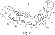
- the 2 now shows a schematic three-dimensional representation of the drilling template 1 according to the invention 1 from below, namely with a view of the bearing surface 1d enclosed by the walls 1a, 1b, 1c.
- the outer wall 1a and inner wall 1c enclose a cavity 5 (dotted line), the cavity 5 being fluidically connected to the through-opening 2 and being formed at least partially below the reinforcement area 2a.
- the cavity 5 has a fluidically active connection to the opening 3 and thus also to the inlet 4a.
- a filter or a grid-like element (not shown) is arranged between the inlet 4a of the fluid-carrying element 4 and the opening 3 in order to prevent bone splinters from penetrating into the fluid-carrying element 4 .
- the outlet 4b is essentially aligned with the mouth opening (not visible) (labial).
- the labial orientation of the outlet 4b is again in FIG 3 to see improved.
- the drilling template 1 in a schematic three-dimensional representation, namely recognizable with a view from the front. Alignment towards the mouth opening also simplifies the connection of a suction unit (not shown). It is also clearly visible that the fluid-carrying element 4 separates from the inner wall 1a (not visible, see also 1 ), over the closing bite line or the (occlusal) upper wall 1c aligned according to this, up to the vestibular, in particular labial, outwardly aligned outer wall 1b.
- the fluid-carrying element 8 comprises an inlet 8a, which is formed around an opening, namely the opening 3' in a sealing and fluidically effective manner, or the fluid-carrying element 8 extends through the opening 3' and ends below the reinforcement area 2a so that the inlet 8a is exposed there.
- the opening 3' also has a predetermined orientation.
- the fluid-carrying element 8 is also shown tubular in this illustration. Alternatively, however, a flat-rectangular cross section is also conceivable. Good It is also visible that the outlet 8b of the fluid-carrying element 8 is aligned or positioned essentially to the mouth opening (not visible) (labial) and also to the connection for an external suction device (not shown) for the suction of a fluid and/or a liquid and/or solid drilling residue is provided. In order to bring the outlet 4a and 8a together, different adapters for a suction unit are conceivable. It is clearly evident that the fluid-carrying element 8 is at least partially formed on and/or in the outer wall 1b.
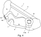
- the inlet 8a is positioned below the reinforcement region 2a and is or can be effectively fluidly connected to the cavity 5 via the opening 3'. It can also be seen that there is a viewing window 7 for optically checking the position in the drilling template 1, with the course of the fluid-carrying element taking the position of the viewing window 7 into account. A web 6 is also visible, which contributes to the structural reinforcement of the drilling template and can also be designed to form further bearing surfaces 1d. It is also conceivable that the fluid-carrying element 4 is an integral part of the web 6 , with the fluid-carrying element 4 also running completely within the web 6 . Alternatively, the fluid-carrying element 8 can also be provided here for introducing a fluid, in particular a gaseous fluid. As a result, uninterrupted cooling of the implant bed can be ensured without a traumatizing temperature increase in the bone, even if there is no coolant flow coupled to the drilling instrument or the drill has been removed from the drilling template.
- FIG 4 now shows a preferred embodiment of FIG 4 illustrated drilling template 1.
- here is an enlarged partial view sketched around the reinforcement area 2a of the through hole 2 viewed from below.
- the outer wall 1a and the inner wall 1c, as well as the bearing surface 1d are partially broken open or cut away.
- a cavity 5 (dash-dotted line) is provided below the reinforcement area 2a.
- the branching 9 is relatively simple here in that it divides the fluid-carrying element 4, in particular the inlet 4a, into two extensions 10a, 10b arranged within the reinforcement area 2a. Provision is made for the coolant to be sucked out together with saliva, blood and abrasion particles via the extensions 10a, 10b.
- the extensions 10a and 10b are open to the cavity 5 provided below the reinforcement area 2a and thus form an annular space.
- the annular space is thus also positioned after the opening 3 in the direction of flow, the opening being sealed off with the fluid-carrying element and thus also the cavity 5 , the cavity 5 being effectively fluidically connected to the through-opening.
- the area around the cavity 5 with the contact surface 1d lies on or in contact with the jaw of the patient, in particular on the gingiva, in a fluid-tight manner.
- the drilling template 1 and the method it is crucial for the drilling template 1 and the method that the drilling template has a fluid-carrying element 4, with the course of the fluid-carrying element 4 during the generation of the virtual draft of the drilling template 1 corresponding to the position or location and alignment of the implant taken into account. Furthermore, the position and alignment of so-called webs 6 and viewing windows 7 can also be taken into account. In this way, selectively effective suction can be implemented, which can also contribute to structural reinforcement of the drilling template.
- a virtual implant plan in particular a 3D implant plan
- a draft of a drilling template 1 is generated, in particular the position or location and orientation of the through opening 2 and the opening 3 and the fluid-carrying element 4, in particular the course, taking into account the position or location specified in the virtual implant planning and orientation of the implant is taken into account.
- the position and orientation of a viewing window 7 and a web 6 can also be taken into account (see also 4 ).
- the method according to the invention can also include the following method steps, in particular in step 201 the virtual draft of the drilling template 1 is proposed to a user for authentication, whereby the user again confirms the correctness of the draft before a digital data record of the virtual drilling template is generated, which then transferred to an apparatus to create a physical model.
- the user can also reject the suggestion, step 202, in order to make changes to the virtual design of the drilling template 1, in particular the position or location and orientation of the through opening 2 and the opening 3 and the fluid-carrying element 4, in particular the course of the fluid-carrying element 4
- the course of the fluid-carrying element 4 can be easily defined as a draft with the following method steps, with step 301 calculating a connecting straight line V1 which connects a predetermined inlet coordinate KE of the inlet and a predetermined outlet coordinate KA of the outlet. Furthermore, in step 302, a connecting straight line V2 is calculated or determined analogously on the basis of a predetermined inlet coordinate KE of the inlet and an implant (reference) coordinate KI. In step 303, a plane E1, which includes at least the connecting line V1 and V2, can now be calculated or spanned or defined.
- step 304 the cutting line S of the plane E1 with the outer wall and/or inner wall and/or upper wall of the drilling template is determined or calculated and in step 305 a fluid-carrying element 4 is generated around the cutting line S on this basis.
- the fluid-carrying element can be tubular or have a flat-rectangular cross-section. It is also conceivable that the fluid-carrying element 4 is simply formed on one of the walls of the drilling template or, as an alternative, is an integral part of the drilling template 1 .
- method step 201 can also be carried out here again, with the previously generated or modified virtual model being proposed to a user for authentication and the user having to confirm the correctness of the design again before a digital data record of the virtual drilling template is generated , which is then ultimately transmitted to a device to create a physical model.
- the user can also reject the suggestion in step 202 in order to make changes to the virtual design of the drilling template 1.
- the course of the cut S, as in the Process step 401 is reproduced, by determining individual course points Pi on the surface of the virtual design of the drilling template 1, in particular the inlet coordinate KE of the inlet and the outlet coordinate KA of the outlet, at least in part.
- method step 402 individual connecting lines Vi are then generated between the course points Pi, with the connecting lines Vi being projected onto the surface of the virtual design of the drilling template 1 and thus depicting the section course S.
- a fluid-carrying element 4 is now produced around the course of the section S.
- the fluid-carrying element 4 can be tubular or have a flat-rectangular cross-section. It is also conceivable that the fluid-carrying element 4 is simply formed on one of the walls of the drilling template or, as an alternative, is an integral part of the drilling template 1 .
- method step 201 can be carried out again, with the previously generated or modified virtual model being suggested to a user for legitimacy and the user having to confirm the correctness of the design again before a digital data record of the virtual drilling template 1 is generated, which then ultimately transferred to a device to create a physical model.
- the user can also reject the suggestion in step 202 in order to make changes to the virtual design of the drilling template 1.
- method step 501 at least one digital data set of the virtual drilling template 1 is generated and, on this basis, in method step 502 a physical drilling template is created with the aid of an additive manufacturing method.
Landscapes
- Health & Medical Sciences (AREA)
- Oral & Maxillofacial Surgery (AREA)
- Dentistry (AREA)
- Epidemiology (AREA)
- Life Sciences & Earth Sciences (AREA)
- Animal Behavior & Ethology (AREA)
- General Health & Medical Sciences (AREA)
- Public Health (AREA)
- Veterinary Medicine (AREA)
- Dental Prosthetics (AREA)
- Dental Tools And Instruments Or Auxiliary Dental Instruments (AREA)
Description
- Die Erfindung betrifft eine Bohrschablone zur Durchführung einer Implantatbohrung für ein dentales Implantat, mit einer Durchgangsöffnung und zumindest einem Durchbruch. Hierzu ist die Bohrschablone zur Auflage bzw. Anlage an einen Kiefer, Gaumen und/oder einen oder mehrere Zähne vorgesehen bzw. anlegbar und ist an die Geometrie des Kiefers, Gaumens und/oder einen oder mehrere Zähne zumindest teilweise angepasst. Die Durchgangsöffnung ist zur Führung eines Bohrers, insbesondere eines Dentalimplantatbohrers, und/oder zum Einsetzten einer Führungshülse für einen Bohrer vorgesehen, und der Durchbruch zur Durchleitung eines Fluides vorgesehen.
- Ferner betrifft die Erfindung ein Verfahren zum virtuellen Entwurf und/oder Herstellung einer Bohrschablone zur Durchführung einer Implantatbohrung für ein dentales Implantat.
- Aus dem Stand der Technik sind bereits unterschiedliche Bohrschablonen im Bereich der zahnärztlichen Implantologie und auch Verfahren zu der Herstellung einer Bohrschablone bekannt.
- Im Wesentlichen beruhen diese Verfahren darauf, dass der Kiefer bzw. die Kieferoberfläche, insbesondere auch der Gaumen und/oder ein oder mehrere Zähne eines Patienten mit einem Negativabdruck oder mit einem bildgebenden computerunterstützen Verfahren dreidimensional (3D) erfasst wird.
- Darüber hinaus sind digitale dreidimensionale Abformverfahren unter Verwendung von intraoralen 3D-Scannern bekannt, wobei derzeit alle am Markt befindlichen Systeme mit lichtoptischen Erfassungstechnologien arbeiten. Beispielsweise sind Systeme bekannt, die auf einem Triangulationsverfahren oder auf konfokaler Abbildung beruhen. Darüber hinaus sind auch andere physikalische Erfassungsmethoden in der Diskussion, beispielsweise die Sonographie, die Erfassung mittels Magnetresonanztomographie, mittels Computertomographie oder mittels digitaler Volumentomographie.
- Mit dem dreidimensional bildgebenden Verfahren wird, insbesondere der Mundraum des Patienten zumindest bereichsweise aufgenommen und zu einem Datensatz verarbeitet, wobei die Position und die Orientierung des Implantats zum Mundraum oder die Positionen und die Orientierungen des/der Implantate zum Mundraum und/oder zueinander erfasst werden.
- Anhand dieser Erfassung, insbesondere aus dem hieraus erzeugten Datensatz, kann dann unter dreidimensionaler (3D)-Visualisierung, das Setzten der Implantate in den Kiefer des Patienten geplant werden. Die Implantatplanung eines oder mehrere Implantate ist Voraussetzung für die Bestimmung benötigter Durchgangsöffnung in der noch zu modellierenden Bohrschablone. Dies geschieht in der Regel mit einer Visualisierungssoftware, bevorzug kommt dabei ein CAD-CAM-Verfahren ("Computer Aided Design" - rechnerunterstütztes Konstruieren - und "Computer Aided Manufacturing" - rechnerunterstützte Fertigung), zum Einsatz.
- Anschließend wird ein Bohrschema bzw. eine zugehörige Bohrschablone ebenfalls virtuell entworfen und insbesondere mittels einem generischen Herstellungsverfahren wie dem Laser-Sinterverfahrens, beispielhaft beschrieben in der
EP 1021 997 A1 , oder der Stereolithographie, beispielhaft beschrieben in derWO 97/29901 A1 - Die zuvor erfassten anatomischen Gegebenheiten bzw. der daraus erzeugte Datensatz umfasst neben anderen Daten auch, die Positionsdaten des zu setzenden Implantats, welche zum Beispiel in Beziehung zu unterschiedlichen Strecken, Flächen, Netzten, kartesischen und/oder Winkelkoordinaten stehen, und bevorzugt in Zuordnung zu dieser Erfassung gespeichert werden.
- Wie bereits angemerkt, ist die Position des Implantats, als auch die Ausrichtung, Voraussetzung bei dem Entwurf des virtuellen Modelles der Bohrschablone. Ein oder mehrere Implantate werden in der Bohrschablone mit einer Durchgangsöffnung berücksichtigt. Die Durchgangsöffnung ist hierbei zur Führung eines Bohrers, insbesondere eines Dentalimplantatbohrers, und/oder zum Einsetzten einer Führungshülse für einen Bohrer vorgesehen ist. Mit dem Bohrer wird eine Bohrung im Kieferknochen eines Patienten gesetzt um anschließend in das resultierende Bohrloch ein Implantat einzubringen. Eine derartige Vorgehensweise ist bereits aus der
DE 10 2016 004 641 A1 bekannt. - Um eine sichere Verankerung und Einheilung des Implantats im Kiefer bzw. Kieferknochen zu gewährleisten, ist es notwendig den Bohrvorgang zur Aufbereitung des Implantatbetts ohne einen schädigenden Temperaturanstieg im Knochen durchzuführen, welcher durch die Bohrreibung verursacht werden kann.
- Um dementsprechend einen unzulässig hohen Temperaturanstieg zu vermeiden wird ein Kühlmittel, insbesondere Wasser oder eine Kochsalzlösung von der Seite auf den Bohrer gespritzt, oder durch den Bohrerschaft möglichst direkt auf die Kontaktfläche zwischen Bohrer und Knochen geleitet, wie in der
DE 100 24 724 A1 vorgeschlagen. - Allerdings ist die notwendige Kühlung nur während des Bohrbetriebs vorhanden und die Kühlwirkung entfällt, wenn das Bohrinstrument und damit auch der Bohrer aus der Bohrschablone herausgenommen werden muss, zum Beispiel um Speichel, Blut und Abriebpartikel aus dem Bohrloch zu entfernen oder bei einem Wechsel des Bohrers selbst. Aus der
EP 0 774 238 A1 ist eine Bohrschablone bekannt, von der diese Erfindung ausgeht, welche das Kühlen sowie das Entfernen von Speichel, Blut und Abriebpartikel während des Bohrbetriebs verbessern soll. Hierzu weist die Bohrschablone eine seitliche Aussparung in der Bohrschablone auf, welche auch den Bohrkanal lateral aufbricht und somit einen Auslass für ein eingebrachtes Kühlmittel, sowie Speichel, Blut und Abriebpartikel ausbildet. - Die
US 2013/280673 A1 offenbart eine Bohrschablone nach dem Oberbegriff von Anspruch 1. - Der vorbekannte Stand der Technik bringt jedoch die Problematik mit sich, dass sich das Kühlmittel zusammen mit Speichel, Blut und Abriebpartikel in dem Rachenraum des Patienten ansammelt. Die hierdurch ausgelösten Schluckreflexe, mitunter auch einen Würgereiz, sind für den Patienten, sowie den Behandelnden höchst unangenehm, und Beeinträchtigen ein präzises Vorgehen während der Behandlung.
- Die Behandlung, insbesondere der Bohrvorgang, muss dann zum Zwecke des Absaugens des Kühlmittels zusammen mit Speichel, Blut und Abriebpartikeln häufig unterbrochen werden, was die Dauer der Behandlung verlängert und dementsprechend auch die Kosten erhöht.
- Die Absaugung wird in den meisten Fällen durch Hilfspersonal übernommen und mit sogenannten Speichelsaugern welche an Absauganlagen angeschlossen sind durchgeführt.
- Es ist daher eine Aufgabe der Erfindung, die Eingangs genannte Bohrschablone nun derart auszugestalten und weiterzubilden, dass das Bohren als Vorbereitung zum Setzen eines Implantats auf eine einfachere, schnellere und kostengünstigere Art und Weise erfolgen kann, wodurch sich Vorteile für den Patienten erschließen, nämlich insbesondere eine verkürzte Behandlungsdauer und eine komfortablere Behandlung an sich, sowie auch Vorteile für die behandelnden Zahnärzte, nämlich geringere resultierende Kosten und einen erhöhte Patientenzufriedenheit.
- Ferner ist es Aufgabe der Erfindung, ein Verfahren bereitzustellen, mit dem ein virtueller Entwurf und/oder die Herstellung einer Bohrschablone durchführbar ist.
- Zur Lösung dieser Aufgabe dient die Bohrschablone mit den Merkmalen des Patentanspruchs 1 und das Verfahren mit den Merkmalen des Patentanspruchs 14. Vorteilhafte Ausführungsformen der Bohrschablone und des Verfahrens sind in den Unteransprüchen aufgeführt.
- Die Bohrschablone ist nunmehr so ausgebildet, dass die Bohrschablone ein fluidführendes Element aufweist, wodurch eine permanente Absaugung vorgenommen werden kann und eine Ansammlung von Kühlmittel zusammen mit Speichel, Blut und Abriebpartikel in dem Rachenraum eines Patienten verhindert oder zumindest gemindert werden.
- Erfindungsgemäß wird durch das Absaugen ein permanent anliegender Unterdruck zwischen der Bohrschablone und dem Kiefer bzw. Gaumen erzeugt, wodurch die Bohrschablone eine zusätzliche Haftung am Kiefer bzw. Gaumen erfährt und somit auch, bei nicht vorhandener manueller Fixierung durch den Behandelnden, sicher in der vorgesehenen Sollposition auf dem Kiefer des Patienten verbleibt.
- Hierzu können ferner auch mehrere fluidführende Elemente vorgesehen sein, um die Absaugwirkung und/oder die Haftung zu verstärken.
- Ferner kann auch ein fluidführendes Element zum Einbringen eines Fluides in die Bohrschablone, insbesondere im Wesentlichen in die Nähe des Implantatbetts bzw. des Bohrlochs vorgesehen sein.
- Hierdurch kann eine ununterbrochene Kühlung des Implantatbetts ohne einen traumatisierenden Temperaturanstieg im Knochen sichergestellt werden, auch wenn kein mit dem Bohrinstrument gekoppeltem Kühlmittelstrom vorhanden ist bzw. der Bohrer aus der Bohrschablone herausgenommen wurde.
- Als Kühlmittel, kann insbesondere auch ein gasförmiges Fluid über das zusätzliche fluidführende Element eingebracht werden, welches schmerzlindernd für den Patienten wirksam ist und wodurch auch eine Ansammlung von weiterem Kühlmittel im Rachenraum vermieden wird.
- Weiterhin wird die zuvor aufgezeigte Aufgabe - für das Verfahren - nun zunächst dadurch gelöst, dass insbesondere die Position bzw. Lage und Ausrichtung der Durchgangsöffnung und des Durchbruchs und des fluidführenden Elements, insbesondere der Verlauf, unter Berücksichtigung der in der virtuellen Implantatplanung festgelegten Position bzw. Lage und Ausrichtung des Implantats bei dem virtuellen Entwurf und/oder Herstellung der Bohrschablone berücksichtigt wird.
- Die eingangs genannten Nachteile sind daher vermieden und entsprechende Vorteile sind erzielt.
- Es gibt nun eine Vielzahl von Möglichkeiten die erfindungsgemäße Bohrschablone bzw. das erfindungsgemäße Verfahren in vorteilhafter Art und Weise auszugestalten und weiterzubilden. Hierfür darf zunächst auf die dem Patentanspruch 1 bzw. dem Patentanspruch 14 nachgeordneten Patentansprüche verwiesen werden. Die abhängigen Ansprüche betreffen jeweils bevorzugte Ausführungsformen.
- In einer Ausgestaltung der Bohrschablone weist das fluidführende Element einen Einlass und einen Auslass auf, wobei das fluidführende Element durch den Einlass fluidisch wirksam mit dem Durchbruch verbunden bzw. verbindbar ist, wodurch in die unmittelbare Umgebung des Implantatbetts ein Fluid zu- oder abgeführt werden kann. Zudem können auch Bohrrückstände wie z. B. Knochensplitter entfernt, insbesondere abgesaugt werden. Zusätzlich ist es von Vorteil, wenn der Durchbruch eine bestimmte Ausrichtung hat, sodass dieser einfach an das fluidführende Element angeformt werden oder das fluidführende Element einfach durch den Durchbruch hindurchgeführt werden kann, ohne eine Einschnürung auszubilden.
- Zur zusätzlichen Verbesserung des Patientenkomforts trägt bei, dass der Auslass des fluidführenden Elements im Wesentlichen zur Mundöffnung (Labial) oder alternativ zur Wange (Bukkal), ausgerichtet ist. Dies ist besonders platzsparend und lässt somit auch mehr Raum zum Führen des Bohrinstruments.
- Dadurch, dass das fluidführende Element einen röhrenförmigen oder einen flachrechteckförmigen Querschnitt aufweist, kann das fluidführende Element einfach an einer der Wandungen der Bohrschablone angeformt werden, oder ist alternativ integraler Bestandteil der Bohrschablone. Besonders bevorzugt ist eine Ausbildung des fluidführenden Elements, in der dieses teilweise oder vollständig unterhalb der Oberfläche bzw. der Wandung der Bohrschablone, somit gar nicht oder nicht vollständig sichtbar, vorgesehen ist. Hierzu kann das fluidführende Element in/auf der Wangenseite, im Zahnbereich nach außen ausgerichtete (vestibuläre) äußeren Wandung verlaufen, wie auch in/an der zu dem Mundinnenraum (im Zahnbereich nach innen, oral) ausgerichteten inneren Wandung, wie auch zur Schlussbisslinie ausgerichteten (okklusale) oberen Wandung, wobei das fluidführende Element zumindest teilweise an und/oder in einer der Wandungen vorgesehen ist, bzw. integral mit einer der Wandungen ausgebildet ist.
- Erfindungsgemäß weist die Bohrschablone eine Kavität auf, welche durch die äußere Wandung und innere Wandung umschlossen bzw. ausgebildet wird. Hierzu sind die innere und die äußere Wandung bis zur Auflage an die Gingiva ausgebildet und dichten die Kavität gegenüber dem Rachenraum ab. Da die Kavität zudem mit der Durchgangsöffnung fluidisch wirksam verbunden ist, wird hierdurch eine Art "Sammelraum" in der Bohrschablone bereitgestellt. In dem Sammelraum werden insbesondere die Bohrrückstände wie zum Beispiel Knochensplitter aufgenommen, wenn diese auf Grund ihrer Größe nicht absaugbar sind und das fluidführende Element in Folge dessen verstopfen würden. Um bereits den Eintritt von großen Bohrrückständen in das fluidführende Element zu verhindern ist es vorstellbar, zwischen dem Einlass des fluidführenden Elements und dem Durchbruch einen Filter oder ein gitterartiges Element anzuordnen.
- Um eine ausreichende Saugwirkung am Einlass des fluidführenden Elements zu erzielen, ist es vorgesehen am Auslass des fluidführenden Elements einen Anschluss für die Absaugung durch eine handelsübliche dentale Absauganlage anzubringen. Der Anschluss bzw. die Anschlussgeometrie der externen Absauganlage kann hierzu bereits während dem virtuellen Entwurf zur Herstellung der Bohrschablone berücksichtigt werden und aus einem Katalog bzw. einer in der CAD/CAM-Software hinterlegten Datenbank von herstellerspezifischen Anschlussgeometrien ausgewählt werden.
- Der anfänglich vorhandene virtuelle Entwurf der Bohrschablone weist zur Berechnung bzw. Festlegung des fluidförmigen Elementes zumindest eine Einlasskoordinate KE des Einlasses, und eine Austrittskoordinate KA des Auslasses, sowie einen Schnittverlauf S auf, wobei der Schnittverlauf S die Einlasskoordinate KE und die Austrittskoordinate KA linienförmig miteinander verbindet. Insbesondere ist Schnittverlauf S als sogenannter Spline ausgebildet. Vorzugsweise wird der Schnittverlauf und somit im Endeffekt auch das fluidführende Element automatisch berechnet und in den Entwurf der Bohrschablone integriert. Hierzu wird der Schnittverlauf bzw. der Verlauf unter Berücksichtigung der in der virtuellen Implantatplanung festgelegten Position bzw. Lage und Ausrichtung des Implantats geplant. Insbesondere kann auch die Einschubrichtung des Implantats berücksichtigt werden. Ferner werden auch sogenannte "Sichtfenster", "Stege" und die "lichte Weite" (Innendurchmesser) besonders an/in den gekrümmten Bereichen des fluidführenden Elements berücksichtigt. Es können auch noch weitere Koordinaten zur Bildung/Berechnung des Schnittverlaufs manuell eingefügt werden oder der Schnittverlauf bzw. der Verlauf des fluidführenden Elements kann gänzlich manuell entworfen werden. Vorzugsweise werden hierzu auf einer oder mehreren Wandungen bzw. auf der Oberfläche des virtuellen Entwurfs, zumindest die Einlasskoordinate KE und die Austrittskoordinate KA ausgewählt, wobei durch die Einlasskoordinate KE auch ein Teil eines Durchbruchs repräsentiert wird. Soll heißen, dass die Koordinaten, welche den Durchbruch abbilden, zumindest auch die Einlasskoordinate KE umfassen. Anschließend wird von einem CAD/CAM System aufgrund der ausgewählten Koordinaten der Schnittverlauf bzw. der Verlauf des fluidführenden Elements berechnet bzw. gebildet. Dies macht die nachfolgende Herstellung mit einem generischen Verfahren, besonders schnell und kosteneffizient.
- In einer weiteren Ausführungsform, welche auch mittels einem generischen Fertigungsverfahren hergestellt werden kann, weist das fluidführende Element eine Verzweigung auf, insbesondere mehrere Verzweigungen, wobei jede Verzweigung einen zugehörigen Einlass aufweist. Das fluidführende Element kann hier auch mehr als einen Auslass aufweisen. Ferner kann das fluidführende Element auch einen variablen Innendurchmesser aufweisen, welcher die Anzahl der Verzweigungen und den damit verbundenen Druckverlust berücksichtigt. Hierdurch lassen sich an unterschiedlichen Stellen im Mundraum simultan bzw. gleichzeitig ein Fluid und/oder ein flüssiger und/oder ein fester Bohrrückstand aus dem Mundraum, insbesondere aus dem Implantatbett bzw. der Kavität entfernen.
- In einer weiteren Aufführung ist es auch möglich, durch ein weiteres (zweites, drittes oder viertes) fluidführende Element ein Fluid in die Bohrschablone, insbesondere in die Nähe oder direkt zum Implantatbett bzw. zur Bohrung einzubringen. Hierdurch kann eine dauerhafte Kühlung und/oder eine dauerhafte Spülung des Implantatbetts gewährleistet werden, ohne dass es einen Fluidstrom durch das Bohrinstrument benötigt. Besonders bevorzugt kann hierzu ein gasförmiges Fluid in die Nähe oder direkt zum Implantatbett bzw. zur Bohrung eingebracht werden.
- In einer weiteren Ausführung, kann ferner die Bohrschablone auch einen sogenannten "Steg" aufweisen. Durch den Steg soll die Bohrschablone an sich strukturell verstärkt werden und/oder eine zusätzliche Auflage am Kiefer des Patienten ausbilden. Vorteilhafterweise kann auch der sogenannte Steg als ein fluidführendes Element ausgebildet sein oder das fluidführende Element ist zumindest teilweise als integraler Bestandteil eines Stegs ausgebildet, was die Bohrschablone strukturell verstärkt.
- Im Folgenden sollen nun mehrere bevorzugte Ausführungsbeispiele der Erfindung anhand der nachfolgenden Zeichnung und der zugehörenden Beschreibung näher erläutert werden.
- In der Zeichnung zeigt:
-
Fig. 1 in schematischer drei dimensionaler Darstellung die erfindungsgemäße Bohrschablone, nämlich mit Sicht auf die wangenwärts ausgerichtete (vestibuläre) äußere Wandung und die zur Schlussbisslinie ausgerichtete (okklusale) obere Wandung, und -
Fig. 2 in schematischer drei dimensionaler Darstellung die erfindungsgemäße Bohrschablone von unten, nämlich insbesondere mit Sicht auf die Auflagefläche, und -
Fig. 3 in schematischer drei dimensionaler Darstellung die erfindungsgemäße Bohrschablone, nämlich von vorne, und -
Fig. 4 in schematischer drei dimensionaler Darstellung die erfindungsgemäße Bohrschablone, nämlich perspektivisch von der Seite mit einem weiteren fluidführenden Element, und -
Fig. 5 einen vergrößerten Ausschnitt der inFig. 4 dargestellten Bohrschablone von unten, mit einer Verzweigung, und -
Fig. 6 einen schematischeren Ablauf um einen virtuellen Entwurf einer erfindungsgemäßen Bohrschablone zu generieren und/oder die Herstellung einer erfindungsgemäßen Bohrschablone zur Durchführung einer Implantatbohrung für ein dentales Implantat durchzuführen. - Bevor nun auf die entsprechenden Verfahrensschritte näher im Einzelnen eingegangen wird, darf im Folgenden anhand der
Fig. 1 zunächst auf die Bohrschablone 1 bzw. deren wesentlichen Komponenten näher eingegangen werden:
DieFig. 1 zeigt eine Bohrschablone 1 zur Durchführung einer Implantatbohrung für ein dentales Implantat (nicht dargestellt), mit einer Durchgangsöffnung 2 und zumindest einem Durchbruch 3 (nicht zeichnerisch sichtbar, s. a.Fig. 2 ). Die Durchgangsöffnung 2 ist zur Führung eines Bohrers (nicht dargestellt), insbesondere eines Dentalimplantatbohrers, und/oder zum Einsetzten einer Führungshülse (nicht dargestellt) für einen Bohrer vorgesehen. Um eine ausreichende Stabilität der Bohrschablone 1 während des Bohrvorgangs zu gewährleisten ist um die Durchgangsöffnung 2 ein Verstärkungsbereich 2a vorgesehen. Vorzugsweise ist der Verstärkungsbereich 2a ring- oder zylinderförmig ausgeführt. Gut zu erkennen ist auch, dass die Bohrschablone 1 zur Auflage bzw. Anlage an einen Kiefer, Gaumen und/oder einen oder mehrere Zähne (nicht dargestellt) vorgesehen ist bzw. anlegbar ist und an die Geometrie des Kiefers, Gaumens und/oder einen oder mehrere Zähne zumindest teilweise angepasst ist. Dementsprechend ist auch die Auflagefläche 1d (in der Darstellung nicht sichtbar, s. a.Fig. 2 ) ausgeformt um einen exakten Sitz der Bohrschablone 1 zu gewährleisten. Der Durchbruch 3 ist zur Durchleitung eines Fluides, insbesondere zur Absaugung eines Kühlmittels zusammen mit Speichel, Blut und Abriebpartikeln unterhalb des Verstärkungsbereichs 2a positioniert und fluidisch wirksam mit einem fluidführenden Element 4 verbunden. Hierzu ist der Einlass 4a des fluidführenden Elements 4 um den Durchbruch 3 dichtend und fluidisch wirksam angelegt oder das fluidführenden Elements 4 reicht durch den Durchbruch 3 hindurch und endet unterhalb Verstärkungsbereichs 2a, sodass der Einlass 4a dort freiliegt (s. a.Fig. 2 ). Je nach Ausrichtung des Durchbruchs 3, wobei die Ausrichtung auf Grundlage eines Richtungsvektors bestimmt bzw. berechnet, insbesondere wird der Richtungsvektor mit zumindest einer Implantat-(Referenz)-Koordinate KI bestimmt bzw. berechnet, kann der Durchbruch 3 und somit auch der den Durchbruch 3 umgebende Einlass 4a des fluidführenden Elements 4 eine fluidisch optimierte Ausrichtung einnehmen. Ferner ist das fluidführende Element 4 in dieser Darstellung röhrenförmig dargestellt. Alternative ist aber auch ein flach-rechteckförmiger Querschnitt denkbar. Gut sichtbar ist auch, dass der Auslass 4b des fluidführenden Elements 4, welcher grundsätzlich im Wesentlichen zur Mundöffnung (nicht sichtbar) (Labial) ausgerichtet bzw. positioniert ist und zum Anschluss für ein externes Absauggerät (nicht dargestellt) zur Absaugung eines Fluides und/oder eines flüssigen und/oder festen Bohrrückstands vorgesehen ist. Ferner ist auch erkennbar, dass die Bohrschablone 1 eine zum Mundinnenraum (orale) ausgerichtete innere Wandung 1a, eine zur Schlussbisslinie ausgerichtete (okklusale) obere Wandung 1c, und eine wangenwärts, im Zahnbereich nach außen ausgerichtete (vestibuläre) äußere Wandung 1b aufweist (s. a.Fig. 2 ), wobei das fluidführende Element 4 zumindest teilweise an und/oder in der inneren Wandung 1a vorgesehen ist, bzw. integral mit der inneren Wandung 1a, sowie der äußeren Wandung 1b, sowie der oberen Wandung 1c ausgebildet ist. - Die
Fig. 2 zeigt nun eine schematische drei dimensionale Darstellung der erfindungsgemäßen Bohrschablone 1 ausFig. 1 von unten, nämlich mit Sicht auf die von den Wandungen 1a, 1b, 1c umschlossene Auflagefläche 1d. Gut dargestellt ist insbesondere, dass die äußere Wandung 1a und innere Wandung 1c eine Kavität 5 (gepunktete Linie) umschließen, wobei die Kavität 5 mit der Durchgangsöffnung 2 fluidisch wirksam verbunden ist und zumindest teilweise unterhalb des Verstärkungsbereich 2a ausgebildet ist. Erkennbar ist auch, dass die Kavität 5 eine fluidisch wirksam Verbindung zu dem Durchbruch 3 und somit auch zu dem Einlass 4a aufweist. Vorstellbar ist auch, dass zwischen dem Einlass 4a des fluidführenden Elements 4 und dem Durchbruch 3 ein Filter oder ein gitterartiges Element (nicht dargestellt) angeordnet ist um ein Eindringen von Knochensplittern in das fluidführende Element 4 zu verhindern. - Der Auslass 4b ist auch in dieser Darstellung im Wesentlichen zur Mundöffnung (nicht sichtbar) (Labial) ausgerichtet. Die labiale Ausrichtung des Auslasses 4b ist noch mal in der
Fig. 3 verbessert zu sehen. Hier ist die Bohrschablone ausFig. 1 in schematischer drei dimensionaler Darstellung, nämlich mit einer Sicht von vorne zu erkennen. Eine Ausrichtung zur Mundöffnung hin vereinfacht zudem den Anschluss eines Absaugaggregats (nicht dargestellt). Gut sichtbar ist auch das sich das fluidführende Element 4 von der inneren Wandung 1a (nicht sichtbar, s. a.Fig. 1 ), über die Schlussbisslinie bzw. die nach dieser ausgerichteten (okklusale) obere Wandung 1c, bis zur vestibulären, insbesondere labialen, nach außen ausgerichteten äußeren Wandung 1b erstreckt. - In der
Fig. 4 nun eine schematische drei dimensionale Darstellung der erfindungsgemäßen Bohrschablone 1 ausFig. 1 undFig. 2 mit einem weiteren fluidführenden Element 8 skizziert. Wie auch das fluidführende Element 4, umfasst das fluidführende Element 8 einen Einlass 8a, welches um einen Durchbruch, nämlich dem den Durchbruch 3' dichtend und fluidisch wirksam angeformt ist, oder das fluidführenden Elements 8 reicht durch den Durchbruch 3' hindurch und endet unterhalb Verstärkungsbereichs 2a, sodass der Einlass 8a dort freiliegt. Wie der Durchbruch 3, weist auch der Durchbruch 3', eine vorbestimmte Ausrichtung auf. - Ferner ist das fluidführende Element 8 in dieser Darstellung ebenso röhrenförmig dargestellt. Alternative ist aber auch ein flach-rechteckförmiger Querschnitt denkbar. Gut sichtbar ist auch, dass der Auslass 8b des fluidführenden Elements 8, im Wesentlichen zur Mundöffnung (nicht sichtbar) (Labial) ausgerichtet bzw. positioniert ist und auch zum Anschluss für ein externes Absauggerät (nicht dargestellt) zur Absaugung eines Fluides und/oder eines flüssigen und/oder festen Bohrrückstands vorgesehen ist. Um den Auslass 4a und 8a zusammen zu führen sind unterschiedliche Adapter für ein Absaugaggregat denkbar. Gut erkennbar ist, dass das fluidführende Element 8 zumindest teilweise an und/oder in der äußeren Wandung 1b ausgebildet ist. Wie auch der Einlass 4a ist der Einlass 8a unterhalb des Verstärkungsbereichs 2a positioniert und über den Durchbruch 3' mit der Kavität 5 fluidisch wirksam verbunden bzw. verbindbar. Erkennbar ist auch dass ein Sichtfenster 7 zur optischen Überprüfung der Position in der Bohrschablone 1 vorhanden ist, wobei der Verlauf des fluidführenden Elements die Position des Sichtfensters 7 berücksichtigt. Ebenso ist auch ein Steg 6 sichtbar, welcher zur strukturellen Verstärkung der Bohrschablone beiträgt und auch zur Ausbildung weitere Auflageflächen 1d ausgebildet sein kann. Es ist auch denkbar, dass das fluidführende Element 4 integraler Bestandteil des Stegs 6 ist, wobei das fluidführende Element 4 auch komplett innerhalt des Stegs 6 verläuft. Alternativ kann das fluidführende Element 8, hier auch zum Einbringen eines Fluides, insbesondere eines gasförmigen Fluides vorgesehen sein. Hierdurch kann eine ununterbrochene Kühlung des Implantatbetts ohne einen traumatisierenden Temperaturanstieg im Knochen sichergestellt werden, auch wenn kein mit dem Bohrinstrument gekoppeltem Kühlmittelstrom vorhanden ist, bzw. der Bohrer aus der Bohrschablone herausgenommen wurde.
- Die
Fig. 5 zeigt nun eine bevorzugte Ausführungsform der inFig. 4 dargestellten Bohrschablone 1. Insbesondere, ist hier eine vergrößerte Teilansicht um den Verstärkungsbereich 2a der Durchgangsöffnung 2 mit Sicht von unten skizziert. Um die Sicht, auf das zum Teil in der Borschablone liegende bzw. in die Bohrschablone 1 integrierte, fluidführende Elemente 4 und 8 zu ermöglichen, sind teilweise die äußere Wandung 1a und die innere Wandung 1c, sowie die Auflagefläche 1d aufgebrochen bzw. weggeschnitten. Unterhalb des Verstärkungsbereich 2a ist eine Kavität 5 (strichpunktierte Linie) vorgesehen. - Gut sichtbar, ist nun in der aufgebrochenen Ansicht der wesentliche Verlauf der fluidführenden Elementen 4 und 8 innerhalb der Bohrschablone 1. Insbesondere ist jetzt auch sichtbar, dass das fluidführenden Element 4 eine Verzweigung 9 aufweist.
- Die Verzweigung 9 ist hier relativ einfach ausgeführt indem sie das fluidführende Element 4, insbesondere den Einlass 4a in zwei, innerhalb des Verstärkungsbereichs 2a, angeordnete Fortsätze 10a, 10b aufteilt. Es ist vorgesehen, dass über die Fortsätze 10a, 10b das Kühlmittel zusammen mit Speichel, Blut und Abriebpartikeln abgesaugt wird. Hierzu sind die Fortsätze 10a und 10b zu der unterhalb des Verstärkungsbereichs 2a vorgesehenen Kavität 5 offen ausgebildet und formen somit einen Ringraum ab. Der Ringraum ist somit auch in Flussrichtung nach dem Durchbruch 3 positioniert, wobei der Durchbruch mit dem fluidführenden Element dichtend abgeschlossen ist und somit auch die Kavität 5, wobei die Kavität 5 zu der Durchgangsöffnung fluidisch wirksam verbunden ist. Insbesondere liegt der Bereich um Kavität 5 mit der Auflagefläche 1d fluiddichtend auf dem Kiefer des Patienten, insbesondere auf der Gingiva auf bzw. an.
- Im Folgenden darf mit Bezugnahme auf die
Fig. 1 bis Fig. 5 und auf dieFig. 6 , die entsprechenden Verfahrensschritte näher beschrieben werden:
Zunächst ist es bei der Bohrschablone 1 und dem Verfahren entscheidend, dass die Bohrschablone ein fluidführendes Element 4 aufweist, wobei der Verlauf des fluidführenden Elements 4 bei der Erzeugung des virtuellen Entwurfs der Bohrschablone 1 die in der virtuellen Implantatplanung festgelegten Position bzw. Lage und Ausrichtung des Implantats berücksichtigt. Ferner können auch die Position und Ausrichtung von sogenannten Stegen 6 und Sichtfernstern 7 berücksichtigt werden. Somit ist eine punktuell wirksame Absaugung realisierbar, welche auch zu einer strukturellen Verstärkung der Bohrschablone beitragen kann. - In der Ausgestaltung des Verfahrens zum virtuellen Entwurf und/oder Herstellung einer Bohrschablone 1 zur Durchführung einer Implantatbohrung für ein dentales Implantat, wird zunächst im Schritt 101 eine virtuelle Implantatplanung, insbesondere eine 3D-Implantatsplanung bereitgestellt. Anschließend wird im Schritt 102 ein Entwurf einer Bohrschablone 1 erzeugt, wobei insbesondere die Position bzw. Lage und Ausrichtung der Durchgangsöffnung 2 und des Durchbruchs 3 und des fluidführenden Elements 4, insbesondere der Verlauf, unter Berücksichtigung der in der virtuellen Implantatplanung festgelegten Position bzw. Lage und Ausrichtung des Implantats berücksichtigt wird. Es kann auch die Position und Ausrichtung eines Sichtfensters 7 und eines Steg 6 berücksichtigt werden (s. a.
Fig. 4 ). - Das erfindungsgemäße Verfahren kann ferner auch die folgenden Verfahrensschritte umfassen, wobei insbesondere im Schritt 201 der virtuelle Entwurf der Bohrschablone 1 einem Benutzer zur Legitimierung vorgeschlagen wird, wodurch der Benutzer die Richtigkeit des Entwurfs nochmal bestätigt, bevor ein digitaler Datensatz der virtuellen Bohrschablone erzeugt wird, welcher dann an eine Vorrichtung übertragen wird, um ein physische Model zu erzeugen. Alternativ, kann der Benutzer den Vorschlag aber auch ablehnen Schritt 202, um Änderungen an dem virtuellen Entwurf der Bohrschablone 1 vorzunehmen, insbesondere die Position bzw. Lage und Ausrichtung der Durchgangsöffnung 2 und des Durchbruchs 3 und des fluidführenden Elements 4, insbesondere der Verlauf des fluidführenden Elementes 4.
- Der Verlauf des fluidführenden Elements 4 (oder auch 8) kann mit folgenden Verfahrensschritten einfach als Entwurf festgelegt werden, wobei als Schritt 301 eine Verbindungsgerade V1 berechnet wird, welche eine vorherbestimmte Einlasskoordinate KE des Einlasses und eine vorherbestimmte Austrittskoordinate KA des Auslasses miteinander verbindet. Ferner wird im Schritt 302 analog eine Verbindungsgerade V2 auf der Grundlage einer vorherbestimmten Einlasskoordinate KE des Einlasses und einer Implantats-(Referenz)Koordinate KI berechnet bzw. bestimmt. Im Schritt 303 kann nun eine Ebene E1, welche zumindest die Verbindungsgerade V1 und V2 umfasst, berechnet bzw. aufgespannt bzw. festlegt werden. Als Schritt 304 wird nun der Schnittverlauf S der Ebene E1 mit der äußeren Wandung und/oder inneren Wandung und/oder oberen Wandung der Bohrschablone bestimmt bzw. berechnet und im Schritt 305 auf dieser Grundlage ein fluidführendes Element 4 um den Schnittverlauf S erzeugt. Das fluidführende Element kann hierzu röhrenförmig oder einen flach-rechteckförmigen Querschnitt aufweisen. Es ist auch denkbar, dass das fluidführende Element 4 einfach an einer der Wandungen der Bohrschablone angeformt ist oder als Alternative ein integraler Bestandteil der Bohrschablone 1 ist. Wie bereits erläutert, kann auch hier nochmal der Verfahrensschritt 201 durchgeführt werden, wobei einem Benutzer das zuvor erzeugte bzw. geänderte virtuelle Modell zur Legitimierung vorgeschlagen wird und wodurch der Benutzer die Richtigkeit des Entwurfs nochmal bestätigen muss, bevor ein digitaler Datensatz der virtuellen Bohrschablone erzeugt wird, welcher dann letztendlich an eine Vorrichtung übertragen wird um ein physisches Model zu erzeugen. Alternativ kann der Benutzer den Vorschlag aber auch ablehnen Schritt 202 um Änderungen an dem virtuellen Entwurf der Bohrschablone 1 vorzunehmen. Alternativ kann der Schnittverlauf S auch, wie in dem Verfahrensschritt 401 wiedergegeben, durch das bestimmen von einzelnen Verlaufspunkten Pi auf der Oberfläche des virtuellen Entwurfs der Bohrschablone 1, insbesondere der Einlasskoordinate KE des Einlasses und der Austrittskoordinate KA des Auslasses zumindest teilweise vorgegeben werden. Im Verfahrensschritt 402 werden anschließend einzelne Verbindungslinien Vi zwischen den Verlaufspunkten Pi erzeugt, wobei die Verbindungslinien Vi auf die Oberfläche des virtuellen Entwurfs der Bohrschablone 1 projiziert werden und somit den Schnittverlauf S abbilden. Auf dieser Grundlage wird nun im Verfahrensschritt 403 ein fluidführendes Element 4 um den Schnittverlauf S erzeugt. Das fluidführende Element 4 kann hierzu röhrenförmig oder einen flach-rechteckförmigen Querschnitt aufweisen. Es ist auch denkbar, dass das fluidführende Element 4 einfach an einer der Wandungen der Bohrschablone angeformt ist oder als Alternative ein integraler Bestandteil der Bohrschablone 1 ist. Auch hier kann nochmals der Verfahrensschritt 201 durchgeführt werden, wobei einem Benutzer das zuvor erzeugte bzw. geänderte virtuelle Modell zur Legitimierung vorgeschlagen wird und wodurch der Benutzer die Richtigkeit des Entwurfs nochmal bestätigen muss, bevor ein digitaler Datensatz der virtuellen Bohrschablone 1 erzeugt wird, welcher dann letztendlich an eine Vorrichtung übertragen wird um ein physisches Model zu erzeugen. Alternativ kann der Benutzer den Vorschlag aber auch ablehnen Schritt 202 um Änderungen an dem virtuellen Entwurf der Bohrschablone 1 vorzunehmen. Abschließend wird im Verfahrensschritt 501 zumindest ein digitaler Datensatz der virtuellen Bohrschablone 1 erzeugt und auf dessen Grundlage im Verfahrensschritt 502 eine physische Bohrschablone mit Hilfe eines generativen Fertigungsverfahrens.
- Im Ergebnis sind die eingangs genannten Nachteile vermieden und eine Vielzahl von Vorteilen realisiert.
-
- 1
- Bohrschablone
- 1a
- zum Mundinnenraum (oral) ausgerichtete innere Wandung
- 1b
- wangenwärts ausgerichtete (vestibuläre) äußere Wandung
- 1c
- zur Schlussbisslinie ausgerichtete (okklusale) obere Wandung
- 1d
- Auflagefläche
- 2
- Durchgangsöffnung
- 2a
- Verstärkungsbereich
- 3
- Durchbruch
- 4
- fluidführendes Element
- 4a
- Einlass
- 4b
- Auslass
- 5
- Kavität
- 6
- Steg
- 7
- Fenster
- 8
- fluidführendes Element
- 8a
- Einlass
- 8b
- Auslass
- 9
- Verzweigung
- 10a, 10b
- Fortsatz
Claims (15)
- Bohrschablone (1) zur Durchführung einer Implantatbohrung für ein dentales Implantat, mit einer Durchgangsöffnung (2) und zumindest einem Durchbruch (3), wobei die Bohrschablone zur Auflage bzw. Anlage an einen Kiefer, Gaumen und/oder einen oder mehrere Zähne vorgesehen ist bzw. anlegbar ist und an die Geometrie des Kiefers, Gaumens und/oder einen oder mehrere Zähne zumindest teilweise angepasst ist, wobei die Durchgangsöffnung (2) zur Führung eines Bohrers, insbesondere eines Dentalimplantatbohrers, und/oder zum Einsetzten einer Führungshülse für einen Bohrer vorgesehen ist, und wobei der Durchbruch (3) zur Durchleitung eines Fluides vorgesehen ist, wobei die Bohrschablone ein fluidführendes Element (4, 8) aufweist wobei das fluidführende Element (4, 8) zum Absaugen eines flüssigen und/oder festen Bohrrückstands vorgesehen ist,dadurch gekennzeichnet, dass um die Durchgangsöffnung (2) ein Verstärkungsbereich (2a) vorgesehen ist, wobei unterhalb des Verstärkungsbereichs (2a) eine Kavität (5) ausgebildet ist, welche durch eine wangenwärts, vestibulär im Zahnbereich nach außen ausgerichtete äußere Wandung (1b) der Bohrschablone (1) und eine oral in den Mundinnenraum ausgerichtete innere Wandung (1a) umschlossen wird, wobei die innere und die äußere Wandung (1a, 1b) bis zur Auflage an die Gingiva ausgebildet sind und die Kavität (5) gegenüber dem Rachenraum abdichten, wobei die Kavität (5) eine fluidisch wirksame Verbindung zu dem Durchbruch (3) und der Durchgangsöffnung (2) aufweist, wobei die Kavität (5) einen Sammelraum zum Aufnehmen von Bohrrückständen bereitstellt,wobei die Bohrschablone (1) für eine zusätzliche Haftung am Kiefer und/oder Gaumen ausgebildet ist zum Erzeugen eines permanent anliegenden Unterdrucks zwischen der Bohrschablone (1) und dem Kiefer bzw. Gaumen durch das Absaugen.
- Bohrschablone nach Anspruch 1,
dadurch gekennzeichnet, dass
das fluidführende Element (4, 8) einen Einlass (4a, 8a) und einen Auslass (4b, 8b) aufweist, wobei das fluidführende Element (4, 8) durch den Einlass (4a, 8a) fluidisch wirksam mit dem Durchbruch (3, 3') verbunden bzw. verbindbar ist. - Bohrschablone nach Anspruch 1 oder 2,
dadurch gekennzeichnet, dass
die Ausrichtung des Durchbruchs (3, 3') auf Grundlage eines Richtungsvektors bestimmt bzw. berechnet wird. - Bohrschablone nach einem der Ansprüche 1 bis 3,
dadurch gekennzeichnet, dass
der Auslass (4b, 8b) des fluidführenden Elements im Wesentlichen zur Mundöffnung (Labial) oder zur Wange (Bukkal), ausgerichtet ist. - Bohrschablone nach einem der Ansprüche 1 bis 4,
dadurch gekennzeichnet, dass
das fluidführende Element (4, 8) röhrenförmigen oder einen flachrechteckförmigen Querschnitt aufweist. - Bohrschablone nach einem der Ansprüche 1 bis 5,
dadurch gekennzeichnet,
dass das fluidführende Element (4, 8) zumindest teilweise an und/oder in der äußeren Wandung (1b) vorgesehen ist, bzw. integral mit der äußeren Wandung (1b) ausgebildet ist. - Bohrschablone nach einem der Ansprüche 1 bis 6,
dadurch gekennzeichnet,
dass das fluidführende Element (4, 8) zumindest teilweise an und/oder in der inneren Wandung (1a) vorgesehen ist, bzw. integral mit der inneren Wandung (1a) ausgebildet ist. - Bohrschablone nach einem der Ansprüche 1 bis 7,
dadurch gekennzeichnet, dass
die Bohrschablone eine zur Schlussbisslinie ausgerichtete (okklusale) obere Wandung (1c) aufweist, wobei das fluidführende Element (4, 8) zumindest teilweise an und/oder in der oberen Wandung (1c) vorgesehen ist, bzw. integral mit der oberen Wandung (1c) ausgebildet ist. - Bohrschablone nach einem der Ansprüche 1 bis 8,
dadurch gekennzeichnet, dass
das fluidführende Element (4, 8) zumindest teilweise dem Verlauf der äußeren Wandung (1b) und/oder inneren Wandung (1a) und/oder der oberen Wandung (1c) folgend vorgesehen ist. - Bohrschablone nach einem der Ansprüche 1 bis 9,
dadurch gekennzeichnet, dass
das fluidführende Element (4, 8) zumindest teilweise die äußere Wandung (1b) und/oder innere Wandung (1a) und/oder obere Wandung (1c) umfasst bzw. umfassend erzeugt wird, bzw. integral mit der äußeren Wandung (1b) und/oder inneren Wandung (1a) und/oder oberen Wandung (1c) ausgebildet ist. - Bohrschablone nach einem der Ansprüche 1 bis 10,
dadurch gekennzeichnet, dass
zwischen dem Auslass (4b, 8b) des fluidführenden Elements (4) und dem Durchbruch ein Filter oder ein gitterartiges Element angeordnet ist. - Bohrschablone nach einem der Ansprüche 1 bis 11,
dadurch gekennzeichnet, dass
am Auslass (4b, 8b) des fluidführenden Elements (4, 8) Mittel zum Anschluss für die Absaugung eines Fluides und/oder eines flüssigen und/oder festen Bohrrückstands vorgesehen ist bzw. anbringbar sind. - Bohrschablone nach einem der Ansprüche 1 bis 12,
dadurch gekennzeichnet, dassdas fluidführende Element (4, 8) eine Einlasskoordinate KE des Einlasses (4a, 8a), und eine Austrittskoordinate KA des Auslasses (4b, 8b), sowie einen Schnittverlauf S aufweist, wobei der Schnittverlauf S die Einlasskoordinate KE und die Austrittskoordinate KA linienförmig miteinander verbindet, und/oderdass das fluidführende Element (4, 8) eine Verzweigung (9) aufweist, insbesondere mehrere Verzweigungen, und/oderdass die Bohrschablone ein weiteres fluidführendes Element (4, 8) aufweist, wobei das fluidführende Element (4, 8) zum Einbringen eines Fluides, insbesondere eines gasförmigen Fluides vorgesehen ist, und/oderdass die Bohrschablone einen Steg (6) aufweist, wobei das fluidführende Element (4, 8) zumindest teileweise als integraler Bestandteil des Stegs (6) ausgebildet ist. - Verfahren zum virtuellen Entwurf und/oder Herstellung einer Bohrschablone zur Durchführung einer Implantatbohrung für ein dentales Implantat, nach einem der vorhergehenden Ansprüche 1 bis 13 umfassend folgende Verfahrensschritte:- Bereitstellen einer virtuellen Implantatplanung, insbesondere einer 3D-Implantatsplanung,- Erzeugen eines virtuellen Entwurfs einer Bohrschablone, wobei insbesondere die Position bzw. Lage und Ausrichtung der Durchgangsöffnung (2) und des Durchbruchs (3, 3') und des fluidführenden Elements (4, 8), insbesondere der Verlauf, unter Berücksichtigung der in der virtuellen Implantatplanung festgelegten Position bzw. Lage und Ausrichtung des Implantats berücksichtigt wird.
- Verfahren nach Anspruch 14, ferner umfassend folgende Verfahrensschritte:- Berechnen einer Verbindungsgerade V1 auf der Grundlage einer vorherbestimmten Einlasskoordinate KE des Einlasses und einer Austrittskoordinate KA des Auslasses,- Berechnen einer Verbindungsgerade V2 auf der Grundlage einer vorherbestimmten Einlasskoordinate KE des Einlasses und einer Implantats-(Referenz)-Koordinate Kl,- Berechnen bzw. Aufspannen bzw. Festlegen einer Ebene E1 welche die Verbindungsgerade V1 und V2 umfasst,- Berechnen bzw. Bestimmen des Schnittverlaufs S der Ebene E1 mit der äußeren Wandung und/oder inneren Wandung und/oder oberen Wandung der Bohrschablone,- Erzeugen eines fluidführenden Elements auf Grundlage des Schnittverlaufs S, und/oderferner umfassend folgende Verfahrensschritte:- Bestimmen von einzelnen Verlaufspunkten Pi auf der Oberfläche des virtuellen Entwurfs der Bohrschablone, insbesondere der Einlasskoordinate KE des Einlasses und der Austrittskoordinate KA des Auslasses,- Erzeugen von einzelnen Verbindungslinien Vi zwischen den Verlaufspunkten Pi, wobei die Verbindungslinien auf die Oberfläche des virtuellen Entwurfs der Bohrschablone projiziert werden und somit einen Schnittverlauf S abbilden,- Erzeugen eines fluidführenden Elements auf Grundlage des Schnittverlaufs S, und/oderferner umfassend folgende Verfahrensschritte:- Dass der virtuelle Entwurf der Bohrschablone einem Benutzer zur Legitimierung vorgeschlagen wird,- Dass der Benutzer den Vorschlag ablehnen kann, um Änderungen an dem virtuellen Entwurf der Bohrschablone vorzunehmen, insbesondere die Position bzw. Lage und Ausrichtung der Durchgangsöffnung (2) und des Durchbruchs (3, 3') und des fluidführenden Elements (4, 8), insbesondere der Verlauf des fluidführenden Elementes, und/oderferner umfassend folgende Verfahrensschritte:- Erzeugen von zumindest einem digitalen Datensatz der virtuellen Bohrschablone,- Erzeugen einer physischen Bohrschablone mit Hilfe eines generativen Fertigungsverfahrens, auf Grundlage des digitalen Datensatzes.
Applications Claiming Priority (2)
| Application Number | Priority Date | Filing Date | Title |
|---|---|---|---|
| DE102018007982.2A DE102018007982B4 (de) | 2018-10-10 | 2018-10-10 | Bohrschablone zur Durchführung einer Implantatbohrung für ein dentales Implantatsowie Verfahren zum virtuellen Entwurf und zur Herstellung der Bohrschablone |
| PCT/DE2019/100876 WO2020074045A1 (de) | 2018-10-10 | 2019-10-10 | Bohrschablone zur durchführung einer implantatbohrung für ein dentales implantat |
Publications (3)
| Publication Number | Publication Date |
|---|---|
| EP3863554A1 EP3863554A1 (de) | 2021-08-18 |
| EP3863554C0 EP3863554C0 (de) | 2023-06-07 |
| EP3863554B1 true EP3863554B1 (de) | 2023-06-07 |
Family
ID=68732625
Family Applications (1)
| Application Number | Title | Priority Date | Filing Date |
|---|---|---|---|
| EP19812906.6A Active EP3863554B1 (de) | 2018-10-10 | 2019-10-10 | Bohrschablone zur durchführung einer implantatbohrung für ein dentales implantat und verfahren zum virtuellen entwurf und/oder herstellung der bohrschablone |
Country Status (4)
| Country | Link |
|---|---|
| US (1) | US20210307875A1 (de) |
| EP (1) | EP3863554B1 (de) |
| DE (1) | DE102018007982B4 (de) |
| WO (1) | WO2020074045A1 (de) |
Families Citing this family (1)
| Publication number | Priority date | Publication date | Assignee | Title |
|---|---|---|---|---|
| CN114917041A (zh) * | 2022-05-31 | 2022-08-19 | 中南大学湘雅医院 | 一种全冠牙体预备辅助工具套件 |
Citations (2)
| Publication number | Priority date | Publication date | Assignee | Title |
|---|---|---|---|---|
| US20170112592A1 (en) * | 2011-09-16 | 2017-04-27 | Randall C. Groscurth | Method of using an endentulous surgical guide |
| KR101959774B1 (ko) * | 2018-11-29 | 2019-03-19 | 김용서 | 외부 주수 장치를 구비하는 치아 임플란트 시술용 서지컬 가이드 시스템 |
Family Cites Families (10)
| Publication number | Priority date | Publication date | Assignee | Title |
|---|---|---|---|---|
| US5688283A (en) | 1995-11-17 | 1997-11-18 | Knapp; John G. | Drill guide for mandibular staple transosseous implants |
| BE1009947A6 (nl) | 1996-02-15 | 1997-11-04 | Materialise Nv | Werkwijze en inrichting voor het vervaardigen van een driedimensionaal voorwerp uit een hardbaar vloeibaar medium. |
| DE29924925U1 (de) | 1999-01-19 | 2007-06-21 | BEGO Bremer Goldschlägerei Wilh. Herbst GmbH & Co. KG | Dentaler Formkörper und Verwendung einer Vorrichtung zur Herstellung von Zahnersatz und dentalen Hilfsteilen |
| DE10024724C2 (de) | 2000-05-19 | 2003-03-27 | Axel Kirsch | Anschlußstück für einen Bohrer zum Erzeugen von Bohrungen in Knochengewebe und Bohrgerät |
| KR100852572B1 (ko) * | 2008-03-11 | 2008-08-18 | (주)다스테크 | 치과용 의료 기기 |
| DE102010008702B4 (de) * | 2010-02-19 | 2012-09-27 | Kim Kubiack | Verfahren zur Herstellung einer Bohrschablone zum Einbringen von implantologischen Bohrungen |
| US20130280673A1 (en) * | 2012-04-24 | 2013-10-24 | Michael C. Maksim | System and Method for Dental Implants |
| AT515856B1 (de) * | 2014-05-15 | 2016-04-15 | Univ Wien Med | Chirurgische Knochenbohrvorrichtung, Winkelstück für eine solche chirurgische Knochenbohrvorrichtung und Verfahren zur Kühlung einer solchen chirurgischen Knochenbohrvorrichtung |
| DE102016004641A1 (de) | 2016-04-20 | 2017-10-26 | Axel Scheffer | Verfahren und System zur Erfassung der Ausrichtung von wenigstens einer Bohrhülse in einer für die lagerichtige Implantation von Zahnimplantaten hergestellten Bohrschablone |
| FR3058311B1 (fr) * | 2016-11-07 | 2021-10-29 | Smiletech | Dispositif de guidage d'un foret utilise en chirurgie et procede de conception et fabrication associe. |
-
2018
- 2018-10-10 DE DE102018007982.2A patent/DE102018007982B4/de active Active
-
2019
- 2019-10-10 WO PCT/DE2019/100876 patent/WO2020074045A1/de not_active Ceased
- 2019-10-10 US US17/283,525 patent/US20210307875A1/en not_active Abandoned
- 2019-10-10 EP EP19812906.6A patent/EP3863554B1/de active Active
Patent Citations (2)
| Publication number | Priority date | Publication date | Assignee | Title |
|---|---|---|---|---|
| US20170112592A1 (en) * | 2011-09-16 | 2017-04-27 | Randall C. Groscurth | Method of using an endentulous surgical guide |
| KR101959774B1 (ko) * | 2018-11-29 | 2019-03-19 | 김용서 | 외부 주수 장치를 구비하는 치아 임플란트 시술용 서지컬 가이드 시스템 |
Also Published As
| Publication number | Publication date |
|---|---|
| DE102018007982A1 (de) | 2020-04-16 |
| EP3863554C0 (de) | 2023-06-07 |
| DE102018007982B4 (de) | 2025-10-30 |
| WO2020074045A1 (de) | 2020-04-16 |
| US20210307875A1 (en) | 2021-10-07 |
| EP3863554A1 (de) | 2021-08-18 |
Similar Documents
| Publication | Publication Date | Title |
|---|---|---|
| DE102009010699B4 (de) | Verfahren zur Herstellung einer Bohrschablone und Bohrschablone zum Präparieren eines Patienten-Kieferknochens für ein medizinisches Zahn-Implantat | |
| DE102012011238B4 (de) | Verfahren zur Herstellung eines Laboranalogs für Dentalimplantate | |
| EP3388021B1 (de) | Verfahren zur automatischen ermittlung einer einschubrichtung für ein zahnersatzteil | |
| DE102007033989A1 (de) | System und Verfahren für die automatische Konstruktion kieferorthopädischer Bezugspunkte | |
| EP2978384B1 (de) | Verfahren zur planung einer wurzelbehandlung eines patienten | |
| DE102017202817B3 (de) | Vorrichtung zum Führen einer dentalchirurgischen Hohlfräse | |
| DE10029256A1 (de) | Verfahren zur Herstellung einer Bohrschablone zum Implantieren von künstlichen Zähnen | |
| WO2009000505A1 (de) | Fixierungsplatte und verfahren zu ihrer verwendung | |
| DE102016118626A1 (de) | Dentalschablone und Zusammenstellung von Dentalschablonen sowie deren Herstellung | |
| WO2018036853A1 (de) | Zahneinheit sowie verfahren zur herstellung einer prothesenbasis | |
| EP3223743B1 (de) | Bissnahmewerkzeug, bissnahmewerkzeugset sowie geeignetes verfahren zur bissregistrierung | |
| WO2015078701A1 (de) | Künstlicher zahn sowie verfahren zur herstellung einer prothesenbasis | |
| DE102012003811A1 (de) | Zahntechnisch-Zahnärztliches Verfahren und Zahntechnisch-Zahnärztliche Vorrichtung | |
| DE102009003650A1 (de) | Verfahren zum Herstellen eines Abutments | |
| DE19902273A1 (de) | Vorrichtung zur Bestimmung einer Plazierung von Dental-Implantaten im Kieferknochen | |
| DE102009044147A1 (de) | Verfahren zur Erstellung eines digitalen Datenmodells | |
| EP3258880B1 (de) | Passive fit von implantatbrücken und -stegen mittels eines cad/cam tools für die modellfreie erstellung von implantatgetragenen restaurationen | |
| DE102018007982B4 (de) | Bohrschablone zur Durchführung einer Implantatbohrung für ein dentales Implantatsowie Verfahren zum virtuellen Entwurf und zur Herstellung der Bohrschablone | |
| EP3618759B1 (de) | Verfahren zur ermittlung von daten für die herstellung von zahnersatz | |
| DE102006010665B4 (de) | Herstellung von Zahnersatz | |
| EP3826572B1 (de) | Bohrschablone für einen kieferchirurgischen eingriff | |
| EP1278474A2 (de) | Verfahren und vorrichtung zur herstellung von zahnersatz mittels injektionsabdruck | |
| EP3703571B1 (de) | Haltevorrichtung für röntgenfilme | |
| EP4153087B1 (de) | Positionierungselement zum positionieren und fixieren einer bohrschablone | |
| DE102010048090B4 (de) | Verfahren zur Herstellung einer Sägeführungsvorrichtung sowie Sägeführungsvorrichtung zur Knochenblockgewinnung |
Legal Events
| Date | Code | Title | Description |
|---|---|---|---|
| STAA | Information on the status of an ep patent application or granted ep patent |
Free format text: STATUS: UNKNOWN |
|
| STAA | Information on the status of an ep patent application or granted ep patent |
Free format text: STATUS: THE INTERNATIONAL PUBLICATION HAS BEEN MADE |
|
| PUAI | Public reference made under article 153(3) epc to a published international application that has entered the european phase |
Free format text: ORIGINAL CODE: 0009012 |
|
| STAA | Information on the status of an ep patent application or granted ep patent |
Free format text: STATUS: REQUEST FOR EXAMINATION WAS MADE |
|
| 17P | Request for examination filed |
Effective date: 20210510 |
|
| AK | Designated contracting states |
Kind code of ref document: A1 Designated state(s): AL AT BE BG CH CY CZ DE DK EE ES FI FR GB GR HR HU IE IS IT LI LT LU LV MC MK MT NL NO PL PT RO RS SE SI SK SM TR |
|
| GRAP | Despatch of communication of intention to grant a patent |
Free format text: ORIGINAL CODE: EPIDOSNIGR1 |
|
| STAA | Information on the status of an ep patent application or granted ep patent |
Free format text: STATUS: GRANT OF PATENT IS INTENDED |
|
| DAV | Request for validation of the european patent (deleted) | ||
| DAX | Request for extension of the european patent (deleted) | ||
| GRAJ | Information related to disapproval of communication of intention to grant by the applicant or resumption of examination proceedings by the epo deleted |
Free format text: ORIGINAL CODE: EPIDOSDIGR1 |
|
| STAA | Information on the status of an ep patent application or granted ep patent |
Free format text: STATUS: REQUEST FOR EXAMINATION WAS MADE |
|
| INTG | Intention to grant announced |
Effective date: 20220110 |
|
| GRAP | Despatch of communication of intention to grant a patent |
Free format text: ORIGINAL CODE: EPIDOSNIGR1 |
|
| STAA | Information on the status of an ep patent application or granted ep patent |
Free format text: STATUS: GRANT OF PATENT IS INTENDED |
|
| INTC | Intention to grant announced (deleted) | ||
| INTG | Intention to grant announced |
Effective date: 20220216 |
|
| GRAJ | Information related to disapproval of communication of intention to grant by the applicant or resumption of examination proceedings by the epo deleted |
Free format text: ORIGINAL CODE: EPIDOSDIGR1 |
|
| STAA | Information on the status of an ep patent application or granted ep patent |
Free format text: STATUS: REQUEST FOR EXAMINATION WAS MADE |
|
| GRAP | Despatch of communication of intention to grant a patent |
Free format text: ORIGINAL CODE: EPIDOSNIGR1 |
|
| STAA | Information on the status of an ep patent application or granted ep patent |
Free format text: STATUS: GRANT OF PATENT IS INTENDED |
|
| INTC | Intention to grant announced (deleted) | ||
| INTG | Intention to grant announced |
Effective date: 20220513 |
|
| GRAJ | Information related to disapproval of communication of intention to grant by the applicant or resumption of examination proceedings by the epo deleted |
Free format text: ORIGINAL CODE: EPIDOSDIGR1 |
|
| STAA | Information on the status of an ep patent application or granted ep patent |
Free format text: STATUS: REQUEST FOR EXAMINATION WAS MADE |
|
| INTC | Intention to grant announced (deleted) | ||
| GRAP | Despatch of communication of intention to grant a patent |
Free format text: ORIGINAL CODE: EPIDOSNIGR1 |
|
| STAA | Information on the status of an ep patent application or granted ep patent |
Free format text: STATUS: GRANT OF PATENT IS INTENDED |
|
| INTG | Intention to grant announced |
Effective date: 20221124 |
|
| GRAS | Grant fee paid |
Free format text: ORIGINAL CODE: EPIDOSNIGR3 |
|
| GRAA | (expected) grant |
Free format text: ORIGINAL CODE: 0009210 |
|
| STAA | Information on the status of an ep patent application or granted ep patent |
Free format text: STATUS: THE PATENT HAS BEEN GRANTED |
|
| AK | Designated contracting states |
Kind code of ref document: B1 Designated state(s): AL AT BE BG CH CY CZ DE DK EE ES FI FR GB GR HR HU IE IS IT LI LT LU LV MC MK MT NL NO PL PT RO RS SE SI SK SM TR |
|
| REG | Reference to a national code |
Ref country code: GB Ref legal event code: FG4D Free format text: NOT ENGLISH |
|
| REG | Reference to a national code |
Ref country code: CH Ref legal event code: EP Ref country code: AT Ref legal event code: REF Ref document number: 1572504 Country of ref document: AT Kind code of ref document: T Effective date: 20230615 Ref country code: DE Ref legal event code: R096 Ref document number: 502019008131 Country of ref document: DE |
|
| P01 | Opt-out of the competence of the unified patent court (upc) registered |
Effective date: 20230525 |
|
| U01 | Request for unitary effect filed |
Effective date: 20230704 |
|
| U07 | Unitary effect registered |
Designated state(s): AT BE BG DE DK EE FI FR IT LT LU LV MT NL PT SE SI Effective date: 20230713 |
|
| P04 | Withdrawal of opt-out of the competence of the unified patent court (upc) registered |
Effective date: 20230710 |
|
| REG | Reference to a national code |
Ref country code: LT Ref legal event code: MG9D |
|
| PG25 | Lapsed in a contracting state [announced via postgrant information from national office to epo] |
Ref country code: NO Free format text: LAPSE BECAUSE OF FAILURE TO SUBMIT A TRANSLATION OF THE DESCRIPTION OR TO PAY THE FEE WITHIN THE PRESCRIBED TIME-LIMIT Effective date: 20230907 Ref country code: ES Free format text: LAPSE BECAUSE OF FAILURE TO SUBMIT A TRANSLATION OF THE DESCRIPTION OR TO PAY THE FEE WITHIN THE PRESCRIBED TIME-LIMIT Effective date: 20230607 |
|
| U20 | Renewal fee for the european patent with unitary effect paid |
Year of fee payment: 5 Effective date: 20231024 |
|
| PG25 | Lapsed in a contracting state [announced via postgrant information from national office to epo] |
Ref country code: RS Free format text: LAPSE BECAUSE OF FAILURE TO SUBMIT A TRANSLATION OF THE DESCRIPTION OR TO PAY THE FEE WITHIN THE PRESCRIBED TIME-LIMIT Effective date: 20230607 Ref country code: HR Free format text: LAPSE BECAUSE OF FAILURE TO SUBMIT A TRANSLATION OF THE DESCRIPTION OR TO PAY THE FEE WITHIN THE PRESCRIBED TIME-LIMIT Effective date: 20230607 Ref country code: GR Free format text: LAPSE BECAUSE OF FAILURE TO SUBMIT A TRANSLATION OF THE DESCRIPTION OR TO PAY THE FEE WITHIN THE PRESCRIBED TIME-LIMIT Effective date: 20230908 |
|
| PG25 | Lapsed in a contracting state [announced via postgrant information from national office to epo] |
Ref country code: SK Free format text: LAPSE BECAUSE OF FAILURE TO SUBMIT A TRANSLATION OF THE DESCRIPTION OR TO PAY THE FEE WITHIN THE PRESCRIBED TIME-LIMIT Effective date: 20230607 |
|
| PG25 | Lapsed in a contracting state [announced via postgrant information from national office to epo] |
Ref country code: IS Free format text: LAPSE BECAUSE OF FAILURE TO SUBMIT A TRANSLATION OF THE DESCRIPTION OR TO PAY THE FEE WITHIN THE PRESCRIBED TIME-LIMIT Effective date: 20231007 |
|
| PG25 | Lapsed in a contracting state [announced via postgrant information from national office to epo] |
Ref country code: SM Free format text: LAPSE BECAUSE OF FAILURE TO SUBMIT A TRANSLATION OF THE DESCRIPTION OR TO PAY THE FEE WITHIN THE PRESCRIBED TIME-LIMIT Effective date: 20230607 Ref country code: SK Free format text: LAPSE BECAUSE OF FAILURE TO SUBMIT A TRANSLATION OF THE DESCRIPTION OR TO PAY THE FEE WITHIN THE PRESCRIBED TIME-LIMIT Effective date: 20230607 Ref country code: RO Free format text: LAPSE BECAUSE OF FAILURE TO SUBMIT A TRANSLATION OF THE DESCRIPTION OR TO PAY THE FEE WITHIN THE PRESCRIBED TIME-LIMIT Effective date: 20230607 Ref country code: IS Free format text: LAPSE BECAUSE OF FAILURE TO SUBMIT A TRANSLATION OF THE DESCRIPTION OR TO PAY THE FEE WITHIN THE PRESCRIBED TIME-LIMIT Effective date: 20231007 Ref country code: CZ Free format text: LAPSE BECAUSE OF FAILURE TO SUBMIT A TRANSLATION OF THE DESCRIPTION OR TO PAY THE FEE WITHIN THE PRESCRIBED TIME-LIMIT Effective date: 20230607 |
|
| PG25 | Lapsed in a contracting state [announced via postgrant information from national office to epo] |
Ref country code: PL Free format text: LAPSE BECAUSE OF FAILURE TO SUBMIT A TRANSLATION OF THE DESCRIPTION OR TO PAY THE FEE WITHIN THE PRESCRIBED TIME-LIMIT Effective date: 20230607 |
|
| REG | Reference to a national code |
Ref country code: DE Ref legal event code: R097 Ref document number: 502019008131 Country of ref document: DE |
|
| PLBE | No opposition filed within time limit |
Free format text: ORIGINAL CODE: 0009261 |
|
| STAA | Information on the status of an ep patent application or granted ep patent |
Free format text: STATUS: NO OPPOSITION FILED WITHIN TIME LIMIT |
|
| 26N | No opposition filed |
Effective date: 20240308 |
|
| PG25 | Lapsed in a contracting state [announced via postgrant information from national office to epo] |
Ref country code: MC Free format text: LAPSE BECAUSE OF FAILURE TO SUBMIT A TRANSLATION OF THE DESCRIPTION OR TO PAY THE FEE WITHIN THE PRESCRIBED TIME-LIMIT Effective date: 20230607 |
|
| REG | Reference to a national code |
Ref country code: CH Ref legal event code: PL |
|
| PG25 | Lapsed in a contracting state [announced via postgrant information from national office to epo] |
Ref country code: CH Free format text: LAPSE BECAUSE OF NON-PAYMENT OF DUE FEES Effective date: 20231031 |
|
| PG25 | Lapsed in a contracting state [announced via postgrant information from national office to epo] |
Ref country code: CH Free format text: LAPSE BECAUSE OF NON-PAYMENT OF DUE FEES Effective date: 20231031 |
|
| PG25 | Lapsed in a contracting state [announced via postgrant information from national office to epo] |
Ref country code: IE Free format text: LAPSE BECAUSE OF NON-PAYMENT OF DUE FEES Effective date: 20231010 |
|
| PG25 | Lapsed in a contracting state [announced via postgrant information from national office to epo] |
Ref country code: IE Free format text: LAPSE BECAUSE OF NON-PAYMENT OF DUE FEES Effective date: 20231010 |
|
| U20 | Renewal fee for the european patent with unitary effect paid |
Year of fee payment: 6 Effective date: 20241025 |
|
| P05 | Withdrawal of opt-out of the competence of the unified patent court (upc) changed |
Free format text: CASE NUMBER: APP_548309/2023 Effective date: 20230713 |
|
| PG25 | Lapsed in a contracting state [announced via postgrant information from national office to epo] |
Ref country code: CY Free format text: LAPSE BECAUSE OF FAILURE TO SUBMIT A TRANSLATION OF THE DESCRIPTION OR TO PAY THE FEE WITHIN THE PRESCRIBED TIME-LIMIT; INVALID AB INITIO Effective date: 20191010 |
|
| PG25 | Lapsed in a contracting state [announced via postgrant information from national office to epo] |
Ref country code: HU Free format text: LAPSE BECAUSE OF FAILURE TO SUBMIT A TRANSLATION OF THE DESCRIPTION OR TO PAY THE FEE WITHIN THE PRESCRIBED TIME-LIMIT; INVALID AB INITIO Effective date: 20191010 |
|
| U20 | Renewal fee for the european patent with unitary effect paid |
Year of fee payment: 7 Effective date: 20251028 |
|
| PG25 | Lapsed in a contracting state [announced via postgrant information from national office to epo] |
Ref country code: TR Free format text: LAPSE BECAUSE OF FAILURE TO SUBMIT A TRANSLATION OF THE DESCRIPTION OR TO PAY THE FEE WITHIN THE PRESCRIBED TIME-LIMIT Effective date: 20230607 |
|
| PGFP | Annual fee paid to national office [announced via postgrant information from national office to epo] |
Ref country code: GB Payment date: 20251022 Year of fee payment: 7 |
|
| U1H | Name or address of the proprietor changed after the registration of the unitary effect |
Owner name: EXOCAD GMBH; DE |