EP3863485B1 - Surface cleaning apparatus with proximity-triggered user interface - Google Patents
Surface cleaning apparatus with proximity-triggered user interface Download PDFInfo
- Publication number
- EP3863485B1 EP3863485B1 EP19874131.6A EP19874131A EP3863485B1 EP 3863485 B1 EP3863485 B1 EP 3863485B1 EP 19874131 A EP19874131 A EP 19874131A EP 3863485 B1 EP3863485 B1 EP 3863485B1
- Authority
- EP
- European Patent Office
- Prior art keywords
- user
- status
- sensor
- cleaning apparatus
- surface cleaning
- Prior art date
- Legal status (The legal status is an assumption and is not a legal conclusion. Google has not performed a legal analysis and makes no representation as to the accuracy of the status listed.)
- Active
Links
Images


Classifications
-
- A—HUMAN NECESSITIES
- A47—FURNITURE; DOMESTIC ARTICLES OR APPLIANCES; COFFEE MILLS; SPICE MILLS; SUCTION CLEANERS IN GENERAL
- A47L—DOMESTIC WASHING OR CLEANING; SUCTION CLEANERS IN GENERAL
- A47L11/00—Machines for cleaning floors, carpets, furniture, walls, or wall coverings
- A47L11/29—Floor-scrubbing machines characterised by means for taking-up dirty liquid
- A47L11/30—Floor-scrubbing machines characterised by means for taking-up dirty liquid by suction
- A47L11/302—Floor-scrubbing machines characterised by means for taking-up dirty liquid by suction having rotary tools
-
- A—HUMAN NECESSITIES
- A47—FURNITURE; DOMESTIC ARTICLES OR APPLIANCES; COFFEE MILLS; SPICE MILLS; SUCTION CLEANERS IN GENERAL
- A47L—DOMESTIC WASHING OR CLEANING; SUCTION CLEANERS IN GENERAL
- A47L11/00—Machines for cleaning floors, carpets, furniture, walls, or wall coverings
- A47L11/34—Machines for treating carpets in position by liquid, foam, or vapour, e.g. by steam
-
- A—HUMAN NECESSITIES
- A47—FURNITURE; DOMESTIC ARTICLES OR APPLIANCES; COFFEE MILLS; SPICE MILLS; SUCTION CLEANERS IN GENERAL
- A47L—DOMESTIC WASHING OR CLEANING; SUCTION CLEANERS IN GENERAL
- A47L11/00—Machines for cleaning floors, carpets, furniture, walls, or wall coverings
- A47L11/40—Parts or details of machines not provided for in groups A47L11/02 - A47L11/38, or not restricted to one of these groups, e.g. handles, arrangements of switches, skirts, buffers, levers
- A47L11/4002—Installations of electric equipment
- A47L11/4005—Arrangements of batteries or cells; Electric power supply arrangements
-
- A—HUMAN NECESSITIES
- A47—FURNITURE; DOMESTIC ARTICLES OR APPLIANCES; COFFEE MILLS; SPICE MILLS; SUCTION CLEANERS IN GENERAL
- A47L—DOMESTIC WASHING OR CLEANING; SUCTION CLEANERS IN GENERAL
- A47L11/00—Machines for cleaning floors, carpets, furniture, walls, or wall coverings
- A47L11/40—Parts or details of machines not provided for in groups A47L11/02 - A47L11/38, or not restricted to one of these groups, e.g. handles, arrangements of switches, skirts, buffers, levers
- A47L11/4002—Installations of electric equipment
- A47L11/4008—Arrangements of switches, indicators or the like
-
- A—HUMAN NECESSITIES
- A47—FURNITURE; DOMESTIC ARTICLES OR APPLIANCES; COFFEE MILLS; SPICE MILLS; SUCTION CLEANERS IN GENERAL
- A47L—DOMESTIC WASHING OR CLEANING; SUCTION CLEANERS IN GENERAL
- A47L11/00—Machines for cleaning floors, carpets, furniture, walls, or wall coverings
- A47L11/40—Parts or details of machines not provided for in groups A47L11/02 - A47L11/38, or not restricted to one of these groups, e.g. handles, arrangements of switches, skirts, buffers, levers
- A47L11/4011—Regulation of the cleaning machine by electric means; Control systems and remote control systems therefor
-
- A—HUMAN NECESSITIES
- A47—FURNITURE; DOMESTIC ARTICLES OR APPLIANCES; COFFEE MILLS; SPICE MILLS; SUCTION CLEANERS IN GENERAL
- A47L—DOMESTIC WASHING OR CLEANING; SUCTION CLEANERS IN GENERAL
- A47L11/00—Machines for cleaning floors, carpets, furniture, walls, or wall coverings
- A47L11/40—Parts or details of machines not provided for in groups A47L11/02 - A47L11/38, or not restricted to one of these groups, e.g. handles, arrangements of switches, skirts, buffers, levers
- A47L11/4013—Contaminants collecting devices, i.e. hoppers, tanks or the like
- A47L11/4016—Contaminants collecting devices, i.e. hoppers, tanks or the like specially adapted for collecting fluids
- A47L11/4019—Fill level sensors; Security means to prevent overflow, e.g. float valves
-
- A—HUMAN NECESSITIES
- A47—FURNITURE; DOMESTIC ARTICLES OR APPLIANCES; COFFEE MILLS; SPICE MILLS; SUCTION CLEANERS IN GENERAL
- A47L—DOMESTIC WASHING OR CLEANING; SUCTION CLEANERS IN GENERAL
- A47L11/00—Machines for cleaning floors, carpets, furniture, walls, or wall coverings
- A47L11/40—Parts or details of machines not provided for in groups A47L11/02 - A47L11/38, or not restricted to one of these groups, e.g. handles, arrangements of switches, skirts, buffers, levers
- A47L11/4027—Filtering or separating contaminants or debris
- A47L11/403—Means for monitoring filtering operation
-
- A—HUMAN NECESSITIES
- A47—FURNITURE; DOMESTIC ARTICLES OR APPLIANCES; COFFEE MILLS; SPICE MILLS; SUCTION CLEANERS IN GENERAL
- A47L—DOMESTIC WASHING OR CLEANING; SUCTION CLEANERS IN GENERAL
- A47L11/00—Machines for cleaning floors, carpets, furniture, walls, or wall coverings
- A47L11/40—Parts or details of machines not provided for in groups A47L11/02 - A47L11/38, or not restricted to one of these groups, e.g. handles, arrangements of switches, skirts, buffers, levers
- A47L11/4061—Steering means; Means for avoiding obstacles; Details related to the place where the driver is accommodated
-
- A—HUMAN NECESSITIES
- A47—FURNITURE; DOMESTIC ARTICLES OR APPLIANCES; COFFEE MILLS; SPICE MILLS; SUCTION CLEANERS IN GENERAL
- A47L—DOMESTIC WASHING OR CLEANING; SUCTION CLEANERS IN GENERAL
- A47L11/00—Machines for cleaning floors, carpets, furniture, walls, or wall coverings
- A47L11/40—Parts or details of machines not provided for in groups A47L11/02 - A47L11/38, or not restricted to one of these groups, e.g. handles, arrangements of switches, skirts, buffers, levers
- A47L11/408—Means for supplying cleaning or surface treating agents
- A47L11/4083—Liquid supply reservoirs; Preparation of the agents, e.g. mixing devices
-
- A—HUMAN NECESSITIES
- A47—FURNITURE; DOMESTIC ARTICLES OR APPLIANCES; COFFEE MILLS; SPICE MILLS; SUCTION CLEANERS IN GENERAL
- A47L—DOMESTIC WASHING OR CLEANING; SUCTION CLEANERS IN GENERAL
- A47L11/00—Machines for cleaning floors, carpets, furniture, walls, or wall coverings
- A47L11/40—Parts or details of machines not provided for in groups A47L11/02 - A47L11/38, or not restricted to one of these groups, e.g. handles, arrangements of switches, skirts, buffers, levers
- A47L11/4091—Storing or parking devices, arrangements therefor; Means allowing transport of the machine when it is not being used
-
- A—HUMAN NECESSITIES
- A47—FURNITURE; DOMESTIC ARTICLES OR APPLIANCES; COFFEE MILLS; SPICE MILLS; SUCTION CLEANERS IN GENERAL
- A47L—DOMESTIC WASHING OR CLEANING; SUCTION CLEANERS IN GENERAL
- A47L7/00—Suction cleaners adapted for additional purposes; Tables with suction openings for cleaning purposes; Containers for cleaning articles by suction; Suction cleaners adapted to cleaning of brushes; Suction cleaners adapted to taking-up liquids
- A47L7/0004—Suction cleaners adapted to take up liquids, e.g. wet or dry vacuum cleaners
- A47L7/0009—Suction cleaners adapted to take up liquids, e.g. wet or dry vacuum cleaners with means mounted on the nozzle; nozzles specially adapted for the recovery of liquid
-
- A—HUMAN NECESSITIES
- A47—FURNITURE; DOMESTIC ARTICLES OR APPLIANCES; COFFEE MILLS; SPICE MILLS; SUCTION CLEANERS IN GENERAL
- A47L—DOMESTIC WASHING OR CLEANING; SUCTION CLEANERS IN GENERAL
- A47L7/00—Suction cleaners adapted for additional purposes; Tables with suction openings for cleaning purposes; Containers for cleaning articles by suction; Suction cleaners adapted to cleaning of brushes; Suction cleaners adapted to taking-up liquids
- A47L7/0004—Suction cleaners adapted to take up liquids, e.g. wet or dry vacuum cleaners
- A47L7/0023—Recovery tanks
-
- A—HUMAN NECESSITIES
- A47—FURNITURE; DOMESTIC ARTICLES OR APPLIANCES; COFFEE MILLS; SPICE MILLS; SUCTION CLEANERS IN GENERAL
- A47L—DOMESTIC WASHING OR CLEANING; SUCTION CLEANERS IN GENERAL
- A47L9/00—Details or accessories of suction cleaners, e.g. mechanical means for controlling the suction or for effecting pulsating action; Storing devices specially adapted to suction cleaners or parts thereof; Carrying-vehicles specially adapted for suction cleaners
- A47L9/10—Filters; Dust separators; Dust removal; Automatic exchange of filters
- A47L9/19—Means for monitoring filtering operation
-
- A—HUMAN NECESSITIES
- A47—FURNITURE; DOMESTIC ARTICLES OR APPLIANCES; COFFEE MILLS; SPICE MILLS; SUCTION CLEANERS IN GENERAL
- A47L—DOMESTIC WASHING OR CLEANING; SUCTION CLEANERS IN GENERAL
- A47L9/00—Details or accessories of suction cleaners, e.g. mechanical means for controlling the suction or for effecting pulsating action; Storing devices specially adapted to suction cleaners or parts thereof; Carrying-vehicles specially adapted for suction cleaners
- A47L9/28—Installation of the electric equipment, e.g. adaptation or attachment to the suction cleaner; Controlling suction cleaners by electric means
- A47L9/2805—Parameters or conditions being sensed
- A47L9/2826—Parameters or conditions being sensed the condition of the floor
-
- A—HUMAN NECESSITIES
- A47—FURNITURE; DOMESTIC ARTICLES OR APPLIANCES; COFFEE MILLS; SPICE MILLS; SUCTION CLEANERS IN GENERAL
- A47L—DOMESTIC WASHING OR CLEANING; SUCTION CLEANERS IN GENERAL
- A47L9/00—Details or accessories of suction cleaners, e.g. mechanical means for controlling the suction or for effecting pulsating action; Storing devices specially adapted to suction cleaners or parts thereof; Carrying-vehicles specially adapted for suction cleaners
- A47L9/28—Installation of the electric equipment, e.g. adaptation or attachment to the suction cleaner; Controlling suction cleaners by electric means
- A47L9/2836—Installation of the electric equipment, e.g. adaptation or attachment to the suction cleaner; Controlling suction cleaners by electric means characterised by the parts which are controlled
- A47L9/2852—Elements for displacement of the vacuum cleaner or the accessories therefor, e.g. wheels, casters or nozzles
-
- A—HUMAN NECESSITIES
- A47—FURNITURE; DOMESTIC ARTICLES OR APPLIANCES; COFFEE MILLS; SPICE MILLS; SUCTION CLEANERS IN GENERAL
- A47L—DOMESTIC WASHING OR CLEANING; SUCTION CLEANERS IN GENERAL
- A47L9/00—Details or accessories of suction cleaners, e.g. mechanical means for controlling the suction or for effecting pulsating action; Storing devices specially adapted to suction cleaners or parts thereof; Carrying-vehicles specially adapted for suction cleaners
- A47L9/28—Installation of the electric equipment, e.g. adaptation or attachment to the suction cleaner; Controlling suction cleaners by electric means
- A47L9/2857—User input or output elements for control, e.g. buttons, switches or displays
-
- A—HUMAN NECESSITIES
- A47—FURNITURE; DOMESTIC ARTICLES OR APPLIANCES; COFFEE MILLS; SPICE MILLS; SUCTION CLEANERS IN GENERAL
- A47L—DOMESTIC WASHING OR CLEANING; SUCTION CLEANERS IN GENERAL
- A47L9/00—Details or accessories of suction cleaners, e.g. mechanical means for controlling the suction or for effecting pulsating action; Storing devices specially adapted to suction cleaners or parts thereof; Carrying-vehicles specially adapted for suction cleaners
- A47L9/28—Installation of the electric equipment, e.g. adaptation or attachment to the suction cleaner; Controlling suction cleaners by electric means
- A47L9/2868—Arrangements for power supply of vacuum cleaners or the accessories thereof
- A47L9/2873—Docking units or charging stations
-
- A—HUMAN NECESSITIES
- A47—FURNITURE; DOMESTIC ARTICLES OR APPLIANCES; COFFEE MILLS; SPICE MILLS; SUCTION CLEANERS IN GENERAL
- A47L—DOMESTIC WASHING OR CLEANING; SUCTION CLEANERS IN GENERAL
- A47L9/00—Details or accessories of suction cleaners, e.g. mechanical means for controlling the suction or for effecting pulsating action; Storing devices specially adapted to suction cleaners or parts thereof; Carrying-vehicles specially adapted for suction cleaners
- A47L9/28—Installation of the electric equipment, e.g. adaptation or attachment to the suction cleaner; Controlling suction cleaners by electric means
- A47L9/2868—Arrangements for power supply of vacuum cleaners or the accessories thereof
- A47L9/2884—Details of arrangements of batteries or their installation
-
- A—HUMAN NECESSITIES
- A47—FURNITURE; DOMESTIC ARTICLES OR APPLIANCES; COFFEE MILLS; SPICE MILLS; SUCTION CLEANERS IN GENERAL
- A47L—DOMESTIC WASHING OR CLEANING; SUCTION CLEANERS IN GENERAL
- A47L9/00—Details or accessories of suction cleaners, e.g. mechanical means for controlling the suction or for effecting pulsating action; Storing devices specially adapted to suction cleaners or parts thereof; Carrying-vehicles specially adapted for suction cleaners
- A47L9/28—Installation of the electric equipment, e.g. adaptation or attachment to the suction cleaner; Controlling suction cleaners by electric means
- A47L9/2894—Details related to signal transmission in suction cleaners
-
- A—HUMAN NECESSITIES
- A47—FURNITURE; DOMESTIC ARTICLES OR APPLIANCES; COFFEE MILLS; SPICE MILLS; SUCTION CLEANERS IN GENERAL
- A47L—DOMESTIC WASHING OR CLEANING; SUCTION CLEANERS IN GENERAL
- A47L9/00—Details or accessories of suction cleaners, e.g. mechanical means for controlling the suction or for effecting pulsating action; Storing devices specially adapted to suction cleaners or parts thereof; Carrying-vehicles specially adapted for suction cleaners
- A47L9/28—Installation of the electric equipment, e.g. adaptation or attachment to the suction cleaner; Controlling suction cleaners by electric means
- A47L9/30—Arrangement of illuminating devices
-
- F—MECHANICAL ENGINEERING; LIGHTING; HEATING; WEAPONS; BLASTING
- F21—LIGHTING
- F21V—FUNCTIONAL FEATURES OR DETAILS OF LIGHTING DEVICES OR SYSTEMS THEREOF; STRUCTURAL COMBINATIONS OF LIGHTING DEVICES WITH OTHER ARTICLES, NOT OTHERWISE PROVIDED FOR
- F21V33/00—Structural combinations of lighting devices with other articles, not otherwise provided for
- F21V33/0004—Personal or domestic articles
- F21V33/0044—Household appliances, e.g. washing machines or vacuum cleaners
-
- G—PHYSICS
- G06—COMPUTING OR CALCULATING; COUNTING
- G06F—ELECTRIC DIGITAL DATA PROCESSING
- G06F3/00—Input arrangements for transferring data to be processed into a form capable of being handled by the computer; Output arrangements for transferring data from processing unit to output unit, e.g. interface arrangements
- G06F3/01—Input arrangements or combined input and output arrangements for interaction between user and computer
- G06F3/011—Arrangements for interaction with the human body, e.g. for user immersion in virtual reality
-
- H—ELECTRICITY
- H02—GENERATION; CONVERSION OR DISTRIBUTION OF ELECTRIC POWER
- H02J—ELECTRIC POWER NETWORKS; CIRCUIT ARRANGEMENTS OR SYSTEMS FOR SUPPLYING OR DISTRIBUTING ELECTRIC POWER; SYSTEMS FOR STORING ELECTRIC ENERGY
- H02J7/00—Circuit arrangements for charging or discharging batteries or for supplying loads from batteries
- H02J7/80—Circuit arrangements for charging or discharging batteries or for supplying loads from batteries including monitoring or indicating arrangements
- H02J7/82—Control of state of charge [SOC]
-
- H—ELECTRICITY
- H04—ELECTRIC COMMUNICATION TECHNIQUE
- H04W—WIRELESS COMMUNICATION NETWORKS
- H04W4/00—Services specially adapted for wireless communication networks; Facilities therefor
- H04W4/30—Services specially adapted for particular environments, situations or purposes
- H04W4/33—Services specially adapted for particular environments, situations or purposes for indoor environments, e.g. buildings
-
- A—HUMAN NECESSITIES
- A47—FURNITURE; DOMESTIC ARTICLES OR APPLIANCES; COFFEE MILLS; SPICE MILLS; SUCTION CLEANERS IN GENERAL
- A47L—DOMESTIC WASHING OR CLEANING; SUCTION CLEANERS IN GENERAL
- A47L2201/00—Robotic cleaning machines, i.e. with automatic control of the travelling movement or the cleaning operation
- A47L2201/02—Docking stations; Docking operations
- A47L2201/022—Recharging of batteries
-
- A—HUMAN NECESSITIES
- A47—FURNITURE; DOMESTIC ARTICLES OR APPLIANCES; COFFEE MILLS; SPICE MILLS; SUCTION CLEANERS IN GENERAL
- A47L—DOMESTIC WASHING OR CLEANING; SUCTION CLEANERS IN GENERAL
- A47L2201/00—Robotic cleaning machines, i.e. with automatic control of the travelling movement or the cleaning operation
- A47L2201/06—Control of the cleaning action for autonomous devices; Automatic detection of the surface condition before, during or after cleaning
-
- Y—GENERAL TAGGING OF NEW TECHNOLOGICAL DEVELOPMENTS; GENERAL TAGGING OF CROSS-SECTIONAL TECHNOLOGIES SPANNING OVER SEVERAL SECTIONS OF THE IPC; TECHNICAL SUBJECTS COVERED BY FORMER USPC CROSS-REFERENCE ART COLLECTIONS [XRACs] AND DIGESTS
- Y10—TECHNICAL SUBJECTS COVERED BY FORMER USPC
- Y10S—TECHNICAL SUBJECTS COVERED BY FORMER USPC CROSS-REFERENCE ART COLLECTIONS [XRACs] AND DIGESTS
- Y10S320/00—Electricity: battery or capacitor charging or discharging
- Y10S320/18—Indicator or display
- Y10S320/21—State of charge of battery
Definitions
- the fluid recovery system typically includes a recovery tank, a nozzle adjacent the surface to be cleaned and in fluid communication with the recovery tank through a working air conduit, and a source of suction in fluid communication with the working air conduit to draw the cleaning fluid from the surface to be cleaned and through the nozzle and the working air conduit to the recovery tank.
- the recovery tank is periodically emptied of collected fluid and debris, such as by removing the recovery tank from the apparatus and pouring the collected fluid and debris into a sink, toilet, or other drain.
- Some surface cleaning apparatus also include a fluid delivery system that delivers cleaning fluid to a surface to be cleaned.
- Multi-surface vacuum cleaners are adapted for cleaning hard floor surfaces such as tile and hardwood and soft floor surfaces such as carpet and upholstery, and can include fluid delivery and recovery systems.
- Other multi-surface cleaning apparatuses include "dry" vacuum cleaners which can clean different surface types, but do not dispense or recover fluid.
- US9233472 relates to a mobile robot providing environmental mapping for household environmental control.
- the invention relates to a surface cleaning apparatus according to claim 1. Further preferred embodiments are defined by the dependent claims.
- aspects of the invention generally relates to a surface cleaning apparatus.
- aspects relate to an improved user interface for a surface cleaning apparatus.
- a surface cleaning apparatus is provided with a proximity-triggered user interface.
- a surface cleaning apparatus is provided with a user interface configured to provide one or more indicia to the user based on the proximity of the user to the surface cleaning apparatus.
- the functional systems of the surface cleaning apparatus can be arranged into any desired configuration, such as an upright device having a base and an upright body for directing the base across the surface to be cleaned, a canister device having a cleaning implement connected to a wheeled base by a vacuum hose, a portable device adapted to be hand carried by a user for cleaning relatively small areas, an autonomous or robotic device, or a commercial device.
- Any of the aforementioned cleaners can be adapted to include a flexible vacuum hose, which can form a portion of the working air conduit between a nozzle and the suction source.
- the surface cleaning apparatus may specifically be in the form of a multi-surface wet vacuum cleaner.
- the term "multi-surface wet vacuum cleaner" includes a vacuum cleaner that can be used to clean hard floor surfaces such as tile and hardwood and soft floor surfaces such as carpet.
- the surface cleaning apparatus can include at least a recovery system for removing the spent cleaning fluid (e.g. liquid) and debris from the surface to be cleaned and storing the spent cleaning fluid and debris.
- the surface cleaning apparatus can optionally further include a fluid delivery system for storing cleaning fluid (e.g. liquid) and delivering the cleaning fluid to the surface to be cleaned.
- Aspects of the invention may also be incorporated into a steam apparatus, such as surface cleaning apparatus with steam delivery.
- Aspects of the invention may also be incorporated into an apparatus with only recovery capabilities, such as surface cleaning apparatus without fluid delivery.
- the surface cleaning apparatus can include a controller operably coupled with the various functional systems of the apparatus for controlling its operation and at least one user interface through which a user of the apparatus interacts with the controller.
- the controller is operably coupled with the at least one user interface for receiving inputs from a user, and can further be operably coupled with at least one sensor for receiving input about the environment and can use the sensor input to control the operation of the surface cleaning apparatus.
- the controller can be operably coupled with at least one proximity sensor configured to detect the presence of a nearby user without any physical contact.
- the controller can use the proximity sensor input to provide one or more indicia about the status of the apparatus to the user via the user interface.
- the indicia may be visual or audible.
- FIG. 1 is a perspective view of a surface cleaning apparatus 10 according to one aspect of the present invention.
- the surface cleaning apparatus 10 is provided with a proximity-triggered user interface, including one or more status indicators which communicate information regarding the apparatus 10 to the user based on the proximity of the user.
- the surface cleaning apparatus 10 is an upright multi-surface wet vacuum cleaner having a housing that includes an upright body or handle assembly 12 and a cleaning head or base 14 mounted to or coupled with the upright handle assembly 12 and adapted for movement across a surface to be cleaned.
- the terms “upper,” “lower,” “right,” “left,” “rear,” “front,” “vertical,” “horizontal,” “inner,” “outer,” and derivatives thereof shall relate to the disclosure as oriented in FIG. 1 from the perspective of a user behind the surface cleaning apparatus 10, which defines the rear of the surface cleaning apparatus 10.
- the invention may assume various alternative orientations, except where expressly specified to the contrary.
- the upright handle assembly 12 comprises an upper handle 16 and a frame 18.
- Frame 18 comprises a main support section or body assembly supporting at least a supply tank assembly 20 and a recovery tank assembly 22, and may further support additional components of the handle assembly 12.
- the surface cleaning apparatus 10 can include a fluid delivery or supply pathway, including and at least partially defined by the supply tank assembly 20, for storing cleaning fluid and delivering the cleaning fluid to the surface to be cleaned and a fluid recovery pathway, including and at least partially defined by the recovery tank assembly 22, for removing the spent cleaning fluid and debris from the surface to be cleaned and storing the spent cleaning fluid and debris until emptied by the user.
- a moveable joint assembly 24 can be formed at a lower end of the frame 18 and moveably mounts the base 14 to the upright assembly 12.
- the base 14 can pivot up and down about at least one axis relative to the upright assembly 12.
- the joint assembly 24 can alternatively comprise a universal joint, such that the base 14 can pivot about at least two axes relative to the upright assembly 12.
- Wiring and/or conduits can optionally supplying air and/or liquid (or other fluids) between the base 14 and the upright assembly 12, or vice versa, can extend though the swivel joint assembly 24.
- a locking mechanism (not shown) can be provided to lock the joint assembly 24 against movement about at least one of the axes of the joint assembly 24.
- the surface cleaning apparatus 10 can include at least one user interface through which a user can interact with the surface cleaning apparatus 10.
- the at least one user interface can enable operation and control of the apparatus 10 from the user's end, and can also provide feedback information from the apparatus 10 to the user.
- the at least one user interface can be electrically coupled with electrical components, including, but not limited to, circuitry electrically connected to various components of the fluid delivery and recovery systems of the surface cleaning apparatus 10.
- the user interface of the surface cleaning apparatus 10 includes a human-machine interface (HMI) 70 having one or more input controls, such as but not limited to buttons, triggers, toggles, keys, switches, or the like, operably connected to systems in the apparatus 10 to affect and control its operation.
- HMI human-machine interface
- the user interface of the surface cleaning apparatus 10 also includes a status user interface (SUI) 72 having at least one status indicator 74 which communicates a condition or status of the apparatus 10 to the user.
- the at least one status indicator 74 can communicate visually and/or audibly.
- the HMI 70 and the SUI 72 can be provided as separate interfaces or can be integrated with each other, such as in a composite user interface, graphical user interface, or multimedia user interface.
- the surface cleaning apparatus 10 can further include a controller 76 ( FIGS. 2 and 7 ) operably coupled with the various function systems of the apparatus 10 for controlling its operation.
- the controller 76 is operably coupled with the HMI 70 for receiving inputs from a user and with the SUI 72 for providing one or more indicia about the status of the apparatus 10 to the user via the at least one status indicator 74, and can further be operably coupled with at least one sensor for receiving input about the environment and can use the sensor input to control the operation of the surface cleaning apparatus 10.
- the controller 76 can be operably coupled with at least one proximity sensor 78 configured to detect the presence of a nearby user without any physical contact.
- the at least one proximity sensor 78 can comprise any suitable configuration, including electromagnetic, ultrasonic, optical, or acoustic, for example.
- suitable proximity sensors include passive infrared (PIR) proximity sensors, microwave proximity sensors, ultrasonic proximity sensors, or photoelectric sensors.
- the at least one proximity sensor 78 can transmit data either through a wired connection or wirelessly.
- the at least one proximity sensor 78 has a wired connection with the controller 76, and transmits proximity data via the wired connection to the controller 76.
- the controller 76 can use the proximity sensor input to provide one or more indicia about the status of the apparatus 10 to the user via the SUI 72.
- the controller 76 can comprise a microcontroller (MCU), and can be located in the upright handle assembly 12, such as in the frame 18 as shown in FIG. 2 .
- the controller 76 is in operable communication with but separate from the HMI 70 and the SUI 72.
- the controller 76 can be integrated with the HMI 70 or the SUI 72.
- the HMI 70 and the SUI 72 are physically separate from each other.
- the HMI 70 in particular is on the handgrip 26, while the SUI 72 is on the frame 18.
- the SUI 72 particularly the status indicators 74, can be directly adjacent the HMI 70 or can be integrated with the HMI 70, such as in a composite user interface, graphical user interface, or multimedia user interface.
- the HMI 70 may be provided elsewhere on the apparatus 10, such as on the frame 18.
- the at least one proximity sensor 78 has a field of view and working range, which together defines a detection zone for the surface cleaning apparatus 10.
- the at least one proximity sensor 78 can be located anywhere on the housing of the apparatus 10, including on the upright handle assembly 12 or base 14, to define a detection zone covering an area exterior of the housing to detect users approaching the apparatus 10.
- the detection zone can be configured to cover at least the front of the surface cleaning apparatus 10, and can include at least one proximity sensor 78 with a field of view of up to 180 degrees. Further, the detection zone can be configured to cover at least the front and sides of the surface cleaning apparatus 10, and can include at least one proximity sensor 78 with a field of view of up to 180 degrees, or greater than 180 degrees, including up to 270 degrees.
- the detection zone can be configured to cover the front, sides, and rear of the surface cleaning apparatus 10, and can include at least one proximity sensor 78 with a field of view of 360 degrees.
- each sensor can have a field of view which collectively define the detection zone, and the fields may be disparate or overlapping.
- Multiple proximity sensors 78 can be employed to provide a detection zone with the coverages described above.
- the working range of the at least proximity sensor 78 can, for example, be at least 2 feet, at least 6 feet, and distances therebetween.
- At least one proximity sensor 78 can be located in the handgrip 26, with a field of view facing generally forward, and/or at least one proximity sensor 78 can be located in the frame 18, such as in an upper portion of the main support section or body assembly, with a field of view facing generally forward.
- the detection zone for the surface cleaning apparatus 10, whether one or both of the sensors 78 are included cover at least the front of the apparatus 10, as well as a portion of the sides of the apparatus 10, and can be approximately 180 degrees or greater than 180 degrees. Such a detection zone detects the presence of a nearby user approaching from the front or sides of the apparatus 10.
- Various other locations for the at least one proximity sensor 78 are possible, such as in the base 14, elsewhere on the handle 16, or elsewhere on the frame 18.
- FIG. 2 is a cross-sectional view of the surface cleaning apparatus 10 through line II-II FIG.1 .
- the upper handle 16 can include a handgrip 26 and the HMI 70.
- the HMI 70 can be provided elsewhere on the surface cleaning apparatus 10, such as on the frame 18.
- a trigger 30 is mounted to the handgrip 26 and operably communicates with the fluid delivery system to control fluid delivery from the surface cleaning apparatus 10.
- Other actuators, such as a thumb switch, can be provided instead of the trigger 30.
- a carry handle 32 can be disposed on the frame 18, forwardly of the handle 16, at an angle to facilitate manual lifting and carrying of the surface cleaning apparatus 10.
- the supply tank assembly 20 can be mounted to the frame 18 in any configuration.
- the supply tank assembly 20 is removably mounted to a housing of the frame 18 such that the supply tank assembly 20 partially rests in the upper rear portion of the frame 18 and can be removed for filling.
- the recovery tank assembly 22 can be mounted to the frame 18 in any configuration.
- the recovery tank assembly 22 is removably mounted to the front of the frame 18, below the supply tank assembly 20, and can be removed for emptying.
- the fluid delivery system is configured to deliver cleaning fluid from the supply tank assembly 20 to a surface to be cleaned, and can include, as briefly discussed above, a fluid delivery or supply pathway.
- the cleaning fluid can comprise one or more of any suitable cleaning fluids, including, but not limited to, water, compositions, concentrated detergent, diluted detergent, etc., and mixtures thereof.
- the fluid can comprise a mixture of water and concentrated detergent.
- the supply tank assembly 20 includes at least one supply chamber 34 for holding cleaning fluid and a supply valve assembly 36 controlling fluid flow through an outlet of the supply chamber 34.
- supply tank assembly 20 can include multiple supply chambers, such as one chamber containing water and another chamber containing a cleaning agent.
- the supply valve assembly 36 can mate with a receiving assembly on the frame 18 and can be configured to automatically open when the supply tank assembly 20 is seated on the frame 18 to release fluid to the fluid delivery pathway.
- the fluid delivery pathway can include a fluid distributor 38 ( FIG. 3 ) having at least one outlet for applying the cleaning fluid to the surface to be cleaned.
- the fluid distributor 38 can be one or more spray tips on the base 14 configured to deliver cleaning fluid to the surface to be cleaned directly or indirectly by spraying a brushroll 40.
- Other embodiments of fluid distributors 38 are possible, such as a spray manifold having multiple outlets or a spray nozzle configured to spray cleaning fluid outwardly from the base 14 in front of the surface cleaning apparatus 10.
- the fluid delivery system can further comprise a flow control system for controlling the flow of fluid from the supply tank assembly 20 to the fluid distributor 38.
- the flow control system can comprise a pump 42 which pressurizes the system.
- the trigger 30 can be operably coupled with the flow control system such that pressing the trigger 30 will deliver fluid from the fluid distributor 38.
- the pump 42 can be positioned within a housing of the frame 18, and in the illustrated embodiment the pump 42 is beneath and in fluid communication with the supply tank assembly 20 via the valve assembly 36.
- the pump 42 can be a centrifugal pump.
- the pump 42 can be a solenoid pump having a single, dual, or variable speed.
- the pump 42 can be eliminated and the flow control system can comprise a gravity-feed system having a valve fluidly coupled with an outlet of the supply tank assembly 20, whereby when valve is open, fluid will flow under the force of gravity to the fluid distributor 38.
- a heater (not shown) can be provided for heating the cleaning fluid prior to delivering the cleaning fluid to the surface to be cleaned.
- an in-line heater can be located downstream of the supply tank assembly 20, and upstream or downstream of the pump 42. Other types of heaters can also be used.
- the cleaning fluid can be heated using exhaust air from a motor-cooling pathway for a suction source of the recovery system.
- the recovery system is configured to remove spent cleaning fluid and debris from the surface to be cleaned and store the spent cleaning fluid and debris on the surface cleaning apparatus 10 for later disposal, and can include, as briefly discussed above, a fluid recovery pathway.
- the fluid recovery pathway can include at least a dirty inlet and a clean outlet.
- the pathway can be formed by, among other elements, a suction nozzle 44 defining the dirty inlet, a suction source 46 in fluid communication with the suction nozzle 44 for generating a working air stream, the recovery tank assembly 22, and exhaust vents 48 ( FIG. 1 ) defining the clean air outlet.
- the recovery tank assembly 22 comprises a recovery tank container 64, which forms the collection container for the fluid recovery system.
- the suction nozzle 44 can be provided on the base 14 can be adapted to be adjacent the surface to be cleaned as the base 14 moves across a surface.
- the brushroll 40 can be provided adjacent to the suction nozzle 44 for agitating the surface to be cleaned so that the debris is more easily ingested into the suction nozzle 44.
- the suction nozzle 44 is further in fluid communication with the recovery tank assembly 22 through a flexible conduit 50.
- the flexible conduit 50 can pass through the joint assembly 24.
- the suction source 46 which may be a motor/fan assembly 46, is provided in fluid communication with the recovery tank assembly 22.
- the motor/fan assembly 46 can be positioned within a housing of the frame 18, such as above the recovery tank assembly 22 and forwardly of the supply tank assembly 20.
- the recovery system can also be provided with one or more additional filters upstream or downstream of the motor/fan assembly 46.
- a pre-motor filter 28 is provided in the working air path downstream of the recovery tank assembly 22 and upstream of the motor/fan assembly.
- Electrical components of the surface cleaning apparatus 10, including the motor/fan assembly 46, the pump 42, and a drive motor for the brushroll 40, can be electrically coupled to a power source 51, such as a battery or a power cord plugged into a household outlet.
- a power source 51 such as a battery or a power cord plugged into a household outlet.
- the power source 51 may comprise a user replaceable battery.
- the power source 51 may comprise a rechargeable battery.
- the battery 51 can be a lithium ion battery.
- the HMI 70 can include one or more switches for controlling actuation of the motor/fan assembly 46, the brushroll 40, and/or the pump 42.
- the HMI 70 can be provided with actuators for selecting between multiple cleaning modes.
- the surface cleaning apparatus 10 can have at least a hard floor cleaning mode, a carpet cleaning mode, and a self-cleaning mode.
- FIG. 3 is a close-up sectional view through a forward section of the base 14.
- the brushroll 40 can be provided at a forward portion of the base 14 and received in a brush chamber 52 on the base 14.
- the brushroll 40 is positioned for rotational movement in a direction R about a central rotational axis X.
- the base 14 includes the suction nozzle 44 that is in fluid communication with the flexible conduit 50 ( FIG. 2 ) and which is defined within the brush chamber 52.
- the suction nozzle 44 is configured to extract fluid and debris from the brushroll 40 and from the surface to be cleaned.
- the brushroll 40 can be operably coupled to and driven by a drive assembly including a dedicated brush motor 53 ( FIG. 7 ) in the base 14.
- the motor/fan assembly 46 can provide both vacuum suction and brushroll rotation.
- the fluid distributor 38 of the present embodiment includes multiple spray tips, though only one spray tip is visible in FIG. 3 , which are mounted to the base 14 with an outlet in the brush chamber 52 and oriented to spray fluid inwardly onto the brushroll 40.
- a front interference wiper 54 is mounted at a forward portion of the brush chamber 52 and is configured to interface with a leading portion of the brushroll 40, as defined by the direction of rotation R of the brushroll 40.
- the interference wiper 54 is below the fluid distributor 38, such that the wetted portion brushroll 40 rotates past the interference wiper 54, which scrapes excess fluid off the brushroll 40, before reaching the surface to be cleaned.
- a rear squeegee 56 is mounted to the base 14 behind the brushroll 40 and the brush chamber 52 and is configured to contact the surface as the base 14 moves across the surface to be cleaned.
- the rear squeegee 56 wipes residual fluid from the surface to be cleaned so that it can be drawn into the fluid recovery pathway via the suction nozzle 44, thereby leaving a moisture and streak-free finish on the surface to be cleaned.
- brushroll 40 can be a hybrid brushroll suitable for use on both hard and soft surfaces, and for wet or dry vacuum cleaning.
- the brushroll 40 comprises a dowel 58, a plurality of bristles 60 extending from the dowel 58, and microfiber material 62 provided on the dowel 58 and arranged between the bristles .
- the surface cleaning apparatus 10 can optionally be provided with a storage tray 66 that can be used when storing the apparatus 10.
- the storage tray 66 can be configured to receive the base 14 of the apparatus 10 in an upright, stored position.
- the storage tray 66 can further be configured for further functionality beyond simple storage, such as for charging the apparatus 10 and/or for self-cleaning of the apparatus 10.
- the storage tray 66 can be a docking station configured to charge the battery 51.
- the storage tray 66 can optionally having charging contacts, and corresponding charging contacts can be provided on the exterior of the apparatus 10, such as on the exterior of the base 14. When operation has ceased, the apparatus 10 can be locked upright and placed into the storage tray 66 for recharging the battery 51.
- the storage tray 66 can be used during a self-cleaning mode of the apparatus 10, which can be used to clean one or more components of the recovery system and/or the fluid delivery system, such as the brushroll 40 and internal components of the fluid recovery pathway of apparatus 10.
- the storage tray 66 can optionally be adapted to contain a liquid for the purposes of cleaning the interior parts of apparatus 10 and/or receiving liquid that may leak from the supply tank assembly 20 while the apparatus 10 is not in active operation. When operation has ceased, the apparatus 10 can be locked upright and placed into the storage tray 66 for cleaning.
- the apparatus 10 is prepared for self-cleaning by coupling the apparatus 10 to the power source 51 and filling the storage tray 66 to a predesignated fill level with a cleaning liquid, such as water.
- the user can select the self-cleaning mode via the HMI 70.
- the suction source 46 and the brush motor 53 are activated, which draws cleaning liquid in the storage tray 66 into the fluid recovery pathway.
- the self-cleaning mode can be configured to last for a predetermined amount of time or until the cleaning liquid in storage tray 66 has been depleted.
- FIG. 5 is an exploded perspective view of the handle 16 of the surface cleaning apparatus 10, showing one embodiment of the HMI 70 for the surface cleaning apparatus 10.
- the HMI 70 as shown herein is provided at a front side of the handgrip 26.
- the HMI 70 can include a printed circuit board (PCB) assembly 80 coupled to the handgrip 26 by a bracket 82.
- PCB printed circuit board
- One or more input controls 84, 86, 88, 90 in register with the PCB assembly 80 are provided on an exterior of the handgrip 26 for user access.
- the input controls 84, 86, 88, 90 can be configured to provide power to one or more electrical components of the apparatus 10, including the suction source 46, the brush motor 53, and the pump 42, in various combinations.
- a waterproof seal (not shown) can optionally be provided around the PCB assembly 80 to protect the PCB assembly 80 from liquid ingress.
- one input control 84 initiates a hard floor cleaning mode
- one input control 86 initiates a carpet cleaning mode
- one input control 88 initiates the self-cleaning mode
- one input control 90 controls the power supply to the SUI 72, as described in further detail below.
- a hard floor cleaning mode the suction source 46, the brush motor 53, and the pump 42 are powered, with the pump 42 operating at a first flow rate.
- the suction source 46, the brush motor 53, and the pump 42 are powered, with the pump 42 operating at a second flow rate which is greater than the first flow rate.
- One or more of the input controls 84, 86, 88, 90 can comprise a button, trigger, toggle, key, switch, or the like, or any combination thereof In one example, one or more of the input controls 84, 86, 88, 90 can comprise a capacitive button.
- the HMI 70 can include at least one light source 92 that emits light.
- the PCB assembly 80 can include at least one light-emitting diode (LED); as shown herein, the PCB assembly 80 can include at least one LED array.
- LED light-emitting diode
- the trigger 30 can be provided on a rear side of the handgrip 26, opposite the HMI 70, and can project at least partially exteriorly of the handgrip 26 for use access.
- a spring 94 can bias the trigger 30 outwardly from the handgrip 26.
- the trigger 30 can electronically communicate with the fluid delivery system. Alternatively, the trigger 30 can mechanically communicate with the fluid delivery system, such as via a push rod (not shown) that runs through the upper handle 16.
- FIG. 6 is a front view of the surface cleaning apparatus 10, showing one embodiment of the SUI 72 for the surface cleaning apparatus 10.
- the SUI 72 as shown herein is provided at a front side of the frame 18, below the handle 16 and above the base 14.
- the SUI 72 can include multiple status indicators 74 which can display various detailed apparatus status information such as, but not limited to, battery status, Wi-Fi connection status, clean water level, dirty water level, filter status, floor type, self-cleaning, or any number of other status information.
- the status indicators 74 can be visual displays for conveying the status of a component of the apparatus 10.
- the visual display may include any of a variety of lights, such as light-emitting diodes (LEDs), textual displays, graphical displays, or any variety of known status indicators.
- the SUI 72 can comprise an LED flexible matrix display.
- the flexible matrix display can, for example, include a printed circuit board (PCB), an isolator, a diffuser, a masking surface, and a decorative layer.
- the flexible matrix display is provided on a front side of the frame 18.
- the SUI 72 can further have an opaque molded plastic part or trim component which encloses and protects portions of the flexible matrix display.
- the SUI 72 can include a battery status indicator 74A, a Wi-Fi connection status indicator 74B, a clean water level status indicator 74C, a dirty water level status indicator 74D, a filter status indicator 74E, a floor type status indicator 74F, and a self-cleaning status indicator 74G.
- the battery status indicator 74A can convey the amount of charge left within the battery 51.
- the battery status indicator 74A includes a battery graphic with three light-emitting diodes, which signal a charge status of approximately 33 percent, 5 approximately 67 percent, and 100 percent. Other configurations for the battery status indicator 74A are possible.
- the Wi-Fi connection status indicator 74B can convey that the apparatus 10 is connected to Wi-Fi, and can be provided for a surface cleaning apparatus that is Wi-Fi enabled.
- the Wi-Fi connection status indicator 74B includes a light-emitting diode (LED) which illuminates when the apparatus 10 is connected to Wi-Fi.
- LED light-emitting diode
- Other configurations for the Wi-Fi connection status indicator 74B are possible.
- the clean water level status indicator 74C can convey the level or amount of clean water within the supply chamber 34.
- the clean water level status indicator 74C includes an LED array configured as a bar graph to indicate the level or amount of clean water in the supply chamber 34.
- Other configurations for the clean water level status indicator 74C are possible.
- the dirty water level status indicator 74D can convey the level or amount of dirty water within the recovery tank container 64.
- the dirty water level status indicator 74D includes an LED array configured as a bar graph to indicate the level or amount of dirty water in the recovery tank container 64.
- Other configurations for the dirty water level status indicator 74D are possible.
- the filter status indicator 74E can convey the status of a filter, such as the pre-motor filter 28.
- the filter status indicator 74E includes a LED which illuminates when the filter 28 needs replacement or cleaning.
- Other configurations for the filter status indicator 74E are possible.
- the floor type status indicator 74F can convey the type of surface below the base 14, such as carpet, including different carpet pile heights like low carpet pile or high carpet pile, or bare floor such as wood, tile, or linoleum.
- the controller 76 may also be in communication with a manual override element allowing a user to manually set the floor type status, which is then displayed by the floor type status indicator 74F.
- the floor type status indicator 74F includes a light-emitting diode which illuminates when bare floors are detected. Other configurations for the floor type status indicator 74F are possible.
- the self-cleaning status indicator 74G can convey that the apparatus 10 is in a self-cleaning mode, described above.
- the self-cleaning status indicator 74G includes a light-emitting diode which illuminates when the apparatus 10 is in the self-cleaning mode.
- Other configurations for the self-cleaning status indicator 74G are possible.
- FIG. 7 is a schematic control diagram for the surface cleaning apparatus 10.
- the apparatus 10 can include at least one other status sensor 96 in communication with the controller 76.
- the status sensor 96 can provide input about at least one component of the apparatus 10, and the controller 76 can use the sensor input to control the operation of the surface cleaning apparatus 10.
- the controller 76 can use sensor input to provide one or more indicia about the status of the apparatus 10 to the user via the status indicators 74A-74G provided on the SUI 72.
- the apparatus 10 can include multiple status sensors 96 which can detect events or changes in its environment related to battery status, Wi-Fi connection status, clean water level, dirty water level, filter status, floor type, self-cleaning, or any number of other status information, and can transmit the information to the controller 76.
- status sensors 96 can detect events or changes in its environment related to battery status, Wi-Fi connection status, clean water level, dirty water level, filter status, floor type, self-cleaning, or any number of other status information, and can transmit the information to the controller 76.
- the sensors can include a battery sensor 96A, a Wi-Fi connection sensor 96B, a clean water level sensor 96C, a dirty water level sensor 96D, a filter sensor 96E, a floor type sensor 96F, and a self-cleaning mode sensor 96G.
- the battery sensor 96A can detect the power capacity or charge level remaining within the battery 51.
- a battery sensor 96A comprises a sensor module configured to measure the discharging and charging current, voltage, and temperature of the battery cells during operation. Other configurations for the battery sensor 96A are possible.
- the Wi-Fi connection sensor 96B can detect the presence of a Wi-Fi network, signal strength, unique router identification data, or any combination thereof, and is configured to connect the apparatus 10 to the internet via a local Wi-Fi network.
- the Wi-Fi connection sensor 96B can comprise a Wi-Fi module for processing Wi-Fi signals and storing firmware, a Wi-Fi antenna for sending and receiving Wi-Fi signals, and optional LEDs for indicating power and Wi-Fi network connection status. Other configurations for the Wi-Fi connection sensor 96B are possible.
- the clean water level sensor 96C can detect the level of clean water within the supply chamber 34.
- the clean water level sensor 96C can comprise a sensing element or apparatus immersed in fluid within the supply chamber 34, such as an electromechanical switch activated by a float, or one or more capacitive, ultrasonic, conductivity, resistive, or optical sensors configured to monitor fluid level within the supply chamber 3. Other configurations for the clean water level sensor 96C are possible.
- the dirty water level sensor 96D can detect the level of dirty water within the recovery tank container 64.
- the dirty water level sensor 96D can comprise a sensing element or apparatus immersed in fluid within the recovery tank container 64, such as an electromechanical switch activated by a float, or one or more capacitive, ultrasonic, conductivity, resistive, or optical sensors configured to monitor fluid level within the tank container 64. Other configurations for the dirty water level sensor 96D are possible.
- the filter sensor 96E can detect when a filter, such as the pre-motor filter 28, needs cleaning and/or replacement.
- a suitable filter sensor 96E is an airflow sensor that detects a decrease in air velocity through the working air flow path of the apparatus 10. This type of sensor can detect a clogged condition of the filter 28, i.e. when the filter 28 becomes so soiled that air flow through the filter 28 is inhibited.
- Another example of a suitable filter sensor 96E is a pressure sensor that detects a drop in pressure in the working air flow path, which also detects a clogged condition of the filter 28.
- the filter sensor 96E can detect an operating time of the apparatus 10, and be configured to prompt the user to clean or replace the filter 28 after a predetermined operating time has elapsed. Other configurations for the filter sensor 96E are possible.
- the floor type sensor 96F can detect the type of surface below the base 14, such as carpet, including different carpet pile heights like low carpet pile or high carpet pile, or bare floor such as wood, tile, or linoleum.
- the floor type sensor 96F can be provided on the base 14, and can comprise any one or combination of known sensor devices, such as, for example, an ultrasonic transducer, optical, acoustic, or mechanical sensor. Other configurations for the floor type sensor 96F are possible.
- the self-cleaning mode sensor 96G can detect when the apparatus 10 is in a self-cleaning mode, described above.
- the self-cleaning mode sensor 96G can be a combination of feedback from components, e.g., voltage feedback from the storage tray 66 confirming the apparatus 10 is docked and a timer that starts after initiation of the self-cleaning mode via the button 88.
- Other configurations for the self-cleaning mode sensor 96G are possible.
- FIGS. 8-11 illustrate one method of operating the proximity-triggered surface cleaning apparatus 10.
- the sequence of steps discussed is for illustrative purposes only and is not meant to limit the method in any way as it is understood that the steps may proceed in a different logical order, additional or intervening steps may be included, or described steps may be divided into multiple steps.
- the area around the surface cleaning apparatus 10 can include at least one detection zone 98, in which the at least one proximity sensor 78 on the surface cleaning apparatus 10 can detect the presence of a nearby user 100 without any physical contact.
- the proximity sensor 78 can more specifically detect the relative proximity of the user 100 to the surface cleaning apparatus 10.
- the proximity sensor 78 can detect the user's presence and provide a signal to the controller 76, which can cause at least the HMI 70 to illuminate, including at least the SUI power button 90, as shown in FIG. 9 .
- the SUI 72 can illuminate and can display status information via at least one status indicator 74, such as, but not limited to, battery status, Wi-Fi connection status, clean water level, dirty water level, filter status, floor type, self-cleaning, or any number of other status information, as shown in FIG. 11 .
- a status indicator 74 such as, but not limited to, battery status, Wi-Fi connection status, clean water level, dirty water level, filter status, floor type, self-cleaning, or any number of other status information, as shown in FIG. 11 .
- the controller 76 When the proximity sensor 78 signals the controller 76, the controller 76 further can ping onboard sensors, such as sensors 96A-96G described above with reference to FIG. 7 , to obtain up-to-date status information, which is then displayed via SUI 72 if the user presses the SUI power button 90 as shown in FIG. 11 .
- the controller 76 can ping the onboard sensors to obtain up-to-date status information, which is then displayed by the SUI 72.
- At least one of the base 14 or the storage tray 66 can include at least one light source 102 that emits light.
- the base 14 can include at least one light source 102 which extends along a front side of the base 14.
- the light source 102 can be in the form of an LED array mounted on a PCB, optionally including at least one light pipe to transmit light across the entire width of the base 14.
- the at least one light source 102 on the base 14 and/or storage tray 66 can illuminate based on the user's presence or based on manipulation of the HMI 70.
- the at least one light source 102 can illuminate before, after, or simultaneously with the SUI 72.
- the at least one light source 102 can illuminate when a user enters the detection zone 98.
- the proximity sensor 78 can detect the user's presence and provide a signal to the controller 76, which can cause at the at least one light source 102 to illuminate.
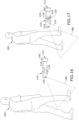
- FIGS. 12-13 illustrate another method of operating the proximity-triggered surface cleaning apparatus 10.
- the sequence of steps discussed is for illustrative purposes only and is not meant to limit the method in any way as it is understood that the steps may proceed in a different logical order, additional or intervening steps may be included, or described steps may be divided into multiple steps.
- the area around the surface cleaning apparatus 10 can include multiple detection zones 104, 106, in which the at least one proximity sensor 78 on the surface cleaning apparatus 10 can detect the presence of a nearby user 100 without any physical contact.
- the proximity sensor 78 can more specifically detect the relative proximity of the user 100 to the surface cleaning apparatus 10.
- a first detection zone 104 and a second detection zone 106 can be located around the surface cleaning apparatus 10, with the first detection zone 104 being further away from the surface cleaning apparatus 10 (e.g. more than 2 feet away, including but not limited to up to - 6 feet away) and the second detection zone 106 being closer to the surface cleaning apparatus 10 (e.g. within 2 feet).
- the at least one proximity sensor 78 can detect the user's presence and provide a signal to the controller 76, which can cause at least the HMI 70 to illuminate, as shown in FIG. 12 .
- the controller 76 further can ping onboard sensors, such as sensors 96A-96G described above with reference to FIG. 7 , to obtain up-to-date status information.
- the brightness of the illumination can increase, and the SUI 72 can illuminate and can display status information via at least one status indicator 74, such as, but not limited to, battery status, Wi-Fi connection status, clean water level, dirty water level, filter status, floor type, self-cleaning, or any number of other status information.
- the method can further include proximity-triggered illumination of the base 14 and/or storage tray 66, as described above with reference to FIG. 11 .
- FIG. 14 is a schematic view of a system for an autonomous surface cleaning apparatus according to another aspect of the invention.
- the system can include an autonomous surface cleaning apparatus 110 and a docking station 112.
- the autonomous surface cleaning apparatus 110 is provided with a proximity-triggered user interface, including one or more status indicators which communicate information regarding the apparatus 110 to the user based on the proximity of the user.
- a suitable autonomous surface cleaning apparatus 110 in which the various features and improvements described herein can be used is a deep cleaning robot which mounts the components of various functional systems of the deep cleaner in an autonomously moveable unit or housing 114, including at least a fluid delivery system for storing cleaning fluid and delivering the cleaning fluid to the surface to be cleaned, a fluid recovery system for removing the cleaning fluid and debris from the surface to be cleaned and storing the recovered cleaning fluid and debris.
- the autonomous surface cleaning apparatus 110 can be a vacuum cleaning robot having a vacuum collection system for removing and collecting debris from the surface to be cleaned.
- the deep cleaning robot 110 further includes a drive system for autonomously moving the robot 110 over the surface to be cleaned.
- the robot 110 can be configured to move randomly about a surface while cleaning the floor surface, using input from various sensors to change direction or adjust its course as needed to avoid obstacles, or, as illustrated herein, can include a navigation/mapping system for guiding the movement of the robot 110 over the surface to be cleaned.
- the robot 110 includes a navigation and path planning system that is operably coupled with the drive system. The system builds and stores a map of the environment in which the autonomous vacuum cleaner 10 is used, and plans paths to methodically clean the available area.
- An artificial barrier system (not shown) can optionally be provided with the robot 110 for containing the robot 110 within a user-determined boundary.
- the deep cleaning robot 110 can include at least one user interface through which a user can interact with the deep cleaning robot.
- the at least one user interface can enable operation and control of the robot 110 from the user's end, and can also provide feedback information from the robot 110 to the user.
- the at least one user interface can be electrically coupled with electrical components, including, but not limited to, circuitry electrically connected to various components of the fluid delivery and recovery systems of the robot 110.
- the robot 110 includes a human-machine interface (HMI) 116 having one or more input controls, such as but not limited to buttons, triggers, toggles, keys, switches, or the like, operably connected to systems in the robot 110 to affect and control its operation.
- the robot 110 also includes a status user interface (SUI) 118 having at least one status indicator 120 which communicates a condition or status of the robot 110 to the user.
- the at least one status indicator 120 can communicate visually and/or audibly.
- the HMI 116 and the SUI 118 can be provided as separate interfaces or can be integrated with each other, such as in a composite user interface, graphical user interface, or multimedia user interface.
- the robot 110 can further be provided with a speaker (not shown) for providing audible notifications to the user.
- the robot 110 can further include a controller 122 operably coupled with the various function systems of the robot 110 for controlling its operation.
- the controller 122 can be a microcontroller unit (MCU) that contains at least one central processing unit (CPU).
- the controller 122 is operably coupled with the HMI 116 for receiving inputs from a user and with the SUI 118 for providing one or more indicia about the status of the robot 110 to the user via the at least one status indicator 120, and can further be operably coupled with at least one sensor for receiving input about the environment and can use the sensor input to control the operation of the robot 110.
- the controller 122 can be operably coupled with at least one proximity sensor 124 configured to detect the presence of a nearby user without any physical contact. In other words, a user need to physically touch the robot 110, including its housing 114, or the proximity sensor 124 for the user's presence to be registered by the controller 122.
- the at least one proximity sensor 124 can comprise any suitable configuration, including electromagnetic, ultrasonic, optical, or acoustic, for example.
- suitable proximity sensors include passive infrared (PIR) proximity sensors, microwave proximity sensors, ultrasonic proximity sensors, or photoelectric sensors.
- PIR passive infrared
- the at least one proximity sensor 124 can be a sensor dedicated to detecting the presence of a nearby user without any physical contact.
- the at least one proximity sensor 124 can be a distance sensor for position sensing, and can be any sensor useful for providing measurements of distance or indications of proximity, including, but not limited to, infrared sensors, time-of-flight sensors, ultrasonic sensors, light detection and ranging (i.e. lidar) sensors, etc.
- Input from the distance sensor is used by the controller 122 to slow down and/or adjust the course of the robot 110 when objects are detected and can also be used to determine the distance to obstacles in front of the robot 110.
- the docking station 112 can further be connected to a household power supply, such as a wall outlet, and can include a converter for converting the AC voltage into DC voltage for recharging a power supply 126 on-board the deep cleaning robot 110, which can be a rechargeable battery or battery pack, such as a lithium ion battery or battery pack.
- the docking station 112 can have charging contacts 128, and corresponding charging contacts 130 can be provided on the exterior of the robot 110, such as on the exterior of the housing 114.
- the docking station 112 can optionally include various sensors and emitters for monitoring robot status, enabling auto-docking functionality, communicating with the robot 110, as well as features for network and/or Bluetooth connectivity.
- the charging contacts 130 of the robot 110 are positioned opposite the sensor 124, such that the sensor 124 faces outward when the robot 110 is docked at the docking station 112 for charging.
- the at least one proximity sensor 124 which can more specifically be at least one distance sensor, and can more specifically be at least one time-of-flight sensor, can detect a change in state in front of the robot 110, i.e. outwardly from the docking station 112, which would indicate a user approaching.
- the user interface including at least one of the HMI 116, SUI 118, and/or the status indicator 120, can illumination in reaction to a user's detected approach.
- FIG. 16 is a schematic view of one embodiment of the deep cleaning robot 110 of FIG. 15 . It is noted that the robot 110 shown in FIG. 2 is but one example of a deep cleaning robot 110 that is usable with the system of FIG. 15 .
- the fluid delivery system can include a supply tank 132 for storing a supply of cleaning fluid and at least one fluid distributor 134 in fluid communication with the supply tank 132 for depositing a cleaning fluid onto the surface.
- the cleaning fluid can be a liquid such as water or a cleaning solution specifically formulated for carpet or hard surface cleaning.
- the fluid distributor 134 can be one or more spray nozzles provided on the housing 114 of the robot 110. Alternatively, the fluid distributor 134 can be a manifold having multiple outlets.
- a fluid delivery pump 136 is provided in the fluid pathway between the supply tank 132 and the fluid distributor 134 to control the flow of fluid to the fluid distributor 134.
- Various combinations of optional components can be incorporated into the fluid delivery system as is commonly known in the art, such as a heater for heating the cleaning fluid before it is applied to the surface or one more fluid control and mixing valves.
- At least one agitator or brush 138 can be provided for agitating the surface to be cleaned onto which fluid has been dispensed.
- the brush 138 can be a brushroll mounted for rotation about a substantially horizontal axis, relative to the surface over which the robot 110 moves.
- a drive assembly including a separate, dedicated brush motor 140 can be provided within the robot 110 to drive the brush 138.
- Other embodiments of agitators are also possible, including one or more stationary or non-moving brushes, or one or more brushes that rotate about a substantially vertical axis.
- the fluid recovery system can include an extraction path through the robot 110 having an extraction or suction nozzle 142 which is positioned to confront the surface to be cleaned and defines the air inlet, the recovery tank 144 for receiving dirt and liquid removed from the surface for later disposal, and a suction source 146 in fluid communication with the suction nozzle 142 and the recovery tank 144 for generating a working air stream through the extraction path.
- the suction source 146 can include a vacuum motor carried by the robot 110, and can define a portion of the extraction path.
- the recovery tank 144 can also define a portion of the extraction path and can comprise an air/liquid separator for separating liquid from the working airstream.
- a pre-motor filter and/or a post-motor filter (not shown) can be provided as well.
- the drive system can include drive wheels 148 for driving the robot 110 across a surface to be cleaned.
- the drive wheels 148 can be operated by a common drive motor or individual drive motors 150 coupled with the drive wheels 148 by a transmission, which may include a gear train assembly or another suitable transmission.
- the drive system can receive inputs from the controller 122 for driving the robot 110 across a floor, based on inputs from the navigation/mapping system.
- the drive wheels 148 can be driven in a forward or reverse direction in order to move the unit forwardly or rearwardly, and can be operated simultaneously or individually in order to turn the unit in a desired direction.
- the controller 122 can receive input from the navigation/mapping system for directing the drive system to move the robot 110 over the surface to be cleaned.
- the navigation/mapping system can include a memory 152 that stores maps for navigation and inputs from various sensors, which is used to guide the movement of the robot 110.
- wheel encoders 154 can be placed on the drive shafts of the wheel motors 150 and are configured to measure the distance travelled. This measurement can be provided as input to the controller 122.
- Motor drivers 156, 158, 160, 162 can be provided for controlling the pump 136, brush motor 140, vacuum motor 146, and wheel motors 150, respectively, and act as an interface between the controller 122 and the components.
- the motor drivers 156-162 may be an integrated circuit chip (IC).
- IC integrated circuit chip
- the motor drivers 156-162 can be electrically coupled to a battery management system 164, which includes the rechargeable battery 126.
- the controller 122 can further be operably coupled with various sensors for receiving input about the environment and can use the sensor input to control the operation of the robot 110.
- the sensor input can further be stored in the memory 152 and/or used to develop maps for navigation.
- the controller 122 can use sensor input to provide one or more indicia about the status of the robot 110 to the user via the at least one status indicator 120 provided on the SUI 118.
- the robot 110 can include multiple sensors which can detect events or changes in its environment related to battery status, Wi-Fi connection status, clean water level, dirty water level, floor type, or any number of other status information, and can transmit the information to the controller 122.
- the robot 110 can include a positioning or localization system having one or more sensors determining the position of the robot relative to objects.
- the localization system can include the at least one distance sensor 124 which doubles as a proximity sensor per the above discussion.
- the at least one distance sensor 124 can be mounted to the housing 114 of the robot 110, such as in the front of robot 110 to determine the distance to obstacles in front of the robot 110. Input from the sensor 124 can be used to slow down and/or adjust the course of the robot 110 when objects are detected, as well to for the proximity-triggered user interface as described in further detail below.
- the robot 110 are at least one cliff sensor 166 that provide distance feedback so that the robot 110 can avoid excessive drops such as stairwells or ledges, at least one bump sensor 168 for determining front or side impacts to the robot 110, at least one wall following sensor 170 that provides distance feedback so that the robot 110 can follow near a wall without contacting the wall, an accelerometer 172 which can be a nine-axis gyroscope or accelerometer to sense linear, rotational and magnetic field acceleration, and/or at least one lift-up sensor 174 which detect when the robot 110 is lifted off the surface to be cleaned, such as when the user picks up the robot 110.
- cliff sensor 166 that provide distance feedback so that the robot 110 can avoid excessive drops such as stairwells or ledges
- at least one bump sensor 168 for determining front or side impacts to the robot 110
- at least one wall following sensor 170 that provides distance feedback so that the robot 110 can follow near a wall without contacting the wall
- an accelerometer 172 which can be a nine-axis
- the robot 110 can further include at least one floor condition sensor 176 for detecting a condition of the surface to be cleaned.
- the robot 110 can be provided with an infrared dirt sensor, a stain sensor, an odor sensor, and/or a wet mess sensor.
- the floor condition sensor 176 provide input to the controller 122, which may direct operation of the robot 110 based on the condition of the surface to be cleaned, such as by selecting or modifying a cleaning cycle.
- the controller 122 can also direct the SUI 118 to provide a notification to the user, such as via the status indicator 120, of the detected floor condition.
- the robot 110 can further include a battery sensor 178 which can detect the amount of charge left within the battery 126, a Wi-Fi connection sensor 180 which can detect whether the robot 110 is connected to a Wi-Fi network, a clean water level sensor 182 which can detect the level of clean water within the supply tank 132, a dirty water level sensor 184 which can detect the level of dirty water within the recovery tank 144, and/or a floor type sensor 186 which can detect the type of surface below the robot 110.
- a battery sensor 178 which can detect the amount of charge left within the battery 126
- a Wi-Fi connection sensor 180 which can detect whether the robot 110 is connected to a Wi-Fi network
- a clean water level sensor 182 which can detect the level of clean water within the supply tank 132
- a dirty water level sensor 184 which can detect the level of dirty water within the recovery tank 144
- a floor type sensor 186 which can detect the type of surface below the robot 110.
- the robot 110 can optionally include one or more sensors for detecting the presence of the supply and recovery tanks 132, 144.
- one or more pressure sensors for detecting the weight of the tanks 132, 144 can be provided. This information is provided as an input to the controller 122, which may prevent operation of the robot 110 until the tanks 132, 144 are properly installed.
- the controller 122 can also direct the SUI 118 to provide a notification to the user, such as via the status indicator 120, that one or both of the tanks 132, 144 is missing.
- FIGS. 16-17 illustrate a method of operating the proximity-triggered robot 110.
- the sequence of steps discussed is for illustrative purposes only and is not meant to limit the method in any way as it is understood that the steps may proceed in a different logical order, additional or intervening steps may be included, or described steps may be divided into multiple steps.
- the area around the robot 110, which is docked at the docking station 112 can include at least one detection zone 188, in which the at least one proximity sensor 124, which may be a distance sensor, on the robot 110 can detect the presence of a nearby user 190 without any physical contact.
- the proximity sensor 124 can more specifically detect the relative proximity of the user 190 to the robot 110.
- the proximity sensor 124 can detect the user's presence and provide a signal to the controller 122 ( FIG. 15 ), which can cause one or both of the HMI 116 or the SUI 118 to illuminate, as shown in FIG. 16 .
- the controller 122 further can ping onboard sensors, such as sensors 178-186 described above with reference to FIG. 15 , to obtain up-to-date status information.
- the brightness of the illumination can increase or ramp up upon continued approach of the user 190.
- the SUI 118 can illuminate, if not already illuminated, and can display status information via at least one status indicator 120, such as, but not limited to, battery status, Wi-Fi connection status, clean water level, dirty water level, filter status, floor type, self-cleaning, or any number of other status information.
- a status indicator 120 such as, but not limited to, battery status, Wi-Fi connection status, clean water level, dirty water level, filter status, floor type, self-cleaning, or any number of other status information.
- one or both of the HMI 116 or the SUI 118 can illuminate when the proximity sensor 124 detects the user 190 within the detection zone 188, and the at least one status indicator 120 can illuminate and display status information upon a further user action, such as pressing a button on the HMI 116 or depressing a bumper of the robot 110, which can be detected by bump sensor 168 ( FIG. 15 ).
- the robot 110 can be configured to detect the presence of a user, i.e. "wake up", when a user initiates physical contact with the robot 110.
- a user can bump, tap, nudge or lift the robot 110 to actuate a sensor, such as the accelerometer 172, bump sensor 168, cliff sensor 166, or lift up sensor 174.
- the accelerometer 172, bump sensor 168, cliff sensor 166, or lift up sensor 174 can provide a signal to the controller 122, which can direct one or both of the HMI 116 or the SUI 118 to illuminate and display up-to-date status information via the status indicator 120.
- the controller 122 can direct one or both of the HMI 116 or the SUI 118 to illuminate and display up-to-date status information via the status indicator 120.
- the above described embodiments provide for a variety of benefits, including improved user interfaces for surface cleaning apparatus. These features, alone or in combination, create a superior user experience.
- An advantage that may be realized in the practice of some embodiments of the described surface cleaning apparatus with a proximity-triggered user interface is that the user of the apparatus is immediately able to see whether the apparatus is ready for operation, i.e. whether a supply chamber has sufficient solution, a recovery tank needs emptying, a filter needs cleaning, or the battery needs charging, etc.
- Another advantage that may be realized in the practice of some embodiments of the described surface cleaning apparatus with a proximity-triggered user interface is that a user does not have to bend down or press a button to turn the apparatus on to see status information.
- the different features and structures of the various aspects or embodiments of the invention may be used in combination with each other as desired or may be used separately. That one surface cleaning apparatus is illustrated herein as having all of these features does not mean that all of these features must be used in combination, but rather done so here for brevity of description.
- the various features of the different embodiments may be mixed and matched in various vacuum cleaner configurations as desired to form new embodiments, whether or not the new embodiments are expressly described.
Landscapes
- Engineering & Computer Science (AREA)
- Mechanical Engineering (AREA)
- General Engineering & Computer Science (AREA)
- Theoretical Computer Science (AREA)
- Robotics (AREA)
- Computer Networks & Wireless Communication (AREA)
- Signal Processing (AREA)
- Human Computer Interaction (AREA)
- Physics & Mathematics (AREA)
- General Physics & Mathematics (AREA)
- Power Engineering (AREA)
- Electric Vacuum Cleaner (AREA)
Description
- Surface cleaning apparatus for cleaning floor surfaces sometimes include fluid recovery systems that extract fluid and debris (which may include dirt, dust, stains, soil, hair, and other debris) from the surface. The fluid recovery system typically includes a recovery tank, a nozzle adjacent the surface to be cleaned and in fluid communication with the recovery tank through a working air conduit, and a source of suction in fluid communication with the working air conduit to draw the cleaning fluid from the surface to be cleaned and through the nozzle and the working air conduit to the recovery tank. The recovery tank is periodically emptied of collected fluid and debris, such as by removing the recovery tank from the apparatus and pouring the collected fluid and debris into a sink, toilet, or other drain.
- Some surface cleaning apparatus also include a fluid delivery system that delivers cleaning fluid to a surface to be cleaned. Multi-surface vacuum cleaners are adapted for cleaning hard floor surfaces such as tile and hardwood and soft floor surfaces such as carpet and upholstery, and can include fluid delivery and recovery systems. Other multi-surface cleaning apparatuses include "dry" vacuum cleaners which can clean different surface types, but do not dispense or recover fluid.
US9233472 - The invention relates to a surface cleaning apparatus according to
claim 1. Further preferred embodiments are defined by the dependent claims. - In the drawings:
-
FIG. 1 is a perspective view of a surface cleaning apparatus according to one aspect of the invention; -
FIG. 2 is a cross-sectional view of the surface cleaning apparatus taken through line II-II ofFIG.1 ; -
FIG. 3 is a sectional view through a portion a base of the surface cleaning apparatus taken through line III-III ofFIG.1 ; -
FIG. 4 is a perspective view of the surface cleaning apparatus ofFIG. 1 docked in a storage tray; -
FIG. 5 is a partially exploded view of a handle of the surface cleaning apparatus, showing one embodiment of a human-machine interface (HMI) for the surface cleaning apparatus; -
FIG. 6 is a close-up front view of a portion of the surface cleaning apparatus, showing one embodiment of a status user interface (SUI) for the surface cleaning apparatus; -
FIG. 7 is a schematic control diagram for the surface cleaning apparatus ofFIG. 1 ; -
FIG. 8 illustrates a user approaching a proximity-triggered surface cleaning apparatus in accordance with a first method of operation; -
FIG. 9 illustrates a HMI for the surface cleaning apparatus ofFIG. 8 illuminating in accordance with the first method of operation; -
FIG. 10 illustrates the user interacting with the HMI ofFIG. 9 in accordance with the first method of operation; -
FIG. 11 illustrates a SUI for the surface cleaning apparatus ofFIG. 8 illuminating in accordance with the first method of operation; -
FIG. 12 illustrates a user approaching a proximity-triggered surface cleaning apparatus and a HMI illuminating in accordance with a second method of operation; -
FIG. 13 illustrates a user continuing to approach the surface cleaning apparatus ofFIG. 12 and a SUI illuminating in accordance with the second method of operation; -
FIG. 14 is a schematic view of a system for an autonomous surface cleaning apparatus according to another aspect of the invention; -
FIG. 15 is a schematic of one embodiment of an autonomous deep cleaner for use in the system ofFIG. 14 ; -
FIG. 16 illustrates a user approaching the proximity-triggered autonomous surface cleaning apparatus ofFIG. 14 in accordance with a third method of operation; and -
FIG. 17 illustrates a user continuing to approach the proximity-triggered autonomous surface cleaning apparatus ofFIG. 14 and at least one status indicator illuminating in accordance with the third method of operation. - Aspects of the invention generally relates to a surface cleaning apparatus. In particular, aspects relate to an improved user interface for a surface cleaning apparatus.
- According to one aspect, a surface cleaning apparatus is provided with a proximity-triggered user interface.
- According to another aspect, a surface cleaning apparatus is provided with a user interface configured to provide one or more indicia to the user based on the proximity of the user to the surface cleaning apparatus.
- According to another aspect, a surface cleaning apparatus is provided with one or more proximity sensors and a user interface configured to receive input from the one or more proximity sensors and provide one or more indicia to the user based on the input.
- The functional systems of the surface cleaning apparatus can be arranged into any desired configuration, such as an upright device having a base and an upright body for directing the base across the surface to be cleaned, a canister device having a cleaning implement connected to a wheeled base by a vacuum hose, a portable device adapted to be hand carried by a user for cleaning relatively small areas, an autonomous or robotic device, or a commercial device. Any of the aforementioned cleaners can be adapted to include a flexible vacuum hose, which can form a portion of the working air conduit between a nozzle and the suction source. The surface cleaning apparatus may specifically be in the form of a multi-surface wet vacuum cleaner. As used herein, the term "multi-surface wet vacuum cleaner" includes a vacuum cleaner that can be used to clean hard floor surfaces such as tile and hardwood and soft floor surfaces such as carpet.
- The surface cleaning apparatus can include at least a recovery system for removing the spent cleaning fluid (e.g. liquid) and debris from the surface to be cleaned and storing the spent cleaning fluid and debris. The surface cleaning apparatus can optionally further include a fluid delivery system for storing cleaning fluid (e.g. liquid) and delivering the cleaning fluid to the surface to be cleaned. Aspects of the invention may also be incorporated into a steam apparatus, such as surface cleaning apparatus with steam delivery. Aspects of the invention may also be incorporated into an apparatus with only recovery capabilities, such as surface cleaning apparatus without fluid delivery.
- The surface cleaning apparatus can include a controller operably coupled with the various functional systems of the apparatus for controlling its operation and at least one user interface through which a user of the apparatus interacts with the controller. The controller is operably coupled with the at least one user interface for receiving inputs from a user, and can further be operably coupled with at least one sensor for receiving input about the environment and can use the sensor input to control the operation of the surface cleaning apparatus.
- For example, the controller can be operably coupled with at least one proximity sensor configured to detect the presence of a nearby user without any physical contact. The controller can use the proximity sensor input to provide one or more indicia about the status of the apparatus to the user via the user interface. The indicia may be visual or audible.
-
FIG. 1 is a perspective view of asurface cleaning apparatus 10 according to one aspect of the present invention. As discussed in further detail below, thesurface cleaning apparatus 10 is provided with a proximity-triggered user interface, including one or more status indicators which communicate information regarding theapparatus 10 to the user based on the proximity of the user. - As illustrated herein, the
surface cleaning apparatus 10 is an upright multi-surface wet vacuum cleaner having a housing that includes an upright body orhandle assembly 12 and a cleaning head orbase 14 mounted to or coupled with theupright handle assembly 12 and adapted for movement across a surface to be cleaned. For purposes of description related to the figures, the terms "upper," "lower," "right," "left," "rear," "front," "vertical," "horizontal," "inner," "outer," and derivatives thereof shall relate to the disclosure as oriented inFIG. 1 from the perspective of a user behind thesurface cleaning apparatus 10, which defines the rear of thesurface cleaning apparatus 10. However, it is to be understood that the invention may assume various alternative orientations, except where expressly specified to the contrary. - The
upright handle assembly 12 comprises anupper handle 16 and aframe 18.Frame 18 comprises a main support section or body assembly supporting at least asupply tank assembly 20 and arecovery tank assembly 22, and may further support additional components of thehandle assembly 12. Thesurface cleaning apparatus 10 can include a fluid delivery or supply pathway, including and at least partially defined by thesupply tank assembly 20, for storing cleaning fluid and delivering the cleaning fluid to the surface to be cleaned and a fluid recovery pathway, including and at least partially defined by therecovery tank assembly 22, for removing the spent cleaning fluid and debris from the surface to be cleaned and storing the spent cleaning fluid and debris until emptied by the user. - A
moveable joint assembly 24 can be formed at a lower end of theframe 18 and moveably mounts thebase 14 to theupright assembly 12. In the embodiment shown herein, thebase 14 can pivot up and down about at least one axis relative to theupright assembly 12. Thejoint assembly 24 can alternatively comprise a universal joint, such that thebase 14 can pivot about at least two axes relative to theupright assembly 12. Wiring and/or conduits can optionally supplying air and/or liquid (or other fluids) between thebase 14 and theupright assembly 12, or vice versa, can extend though theswivel joint assembly 24. A locking mechanism (not shown) can be provided to lock thejoint assembly 24 against movement about at least one of the axes of thejoint assembly 24. - The
surface cleaning apparatus 10 can include at least one user interface through which a user can interact with thesurface cleaning apparatus 10. The at least one user interface can enable operation and control of theapparatus 10 from the user's end, and can also provide feedback information from theapparatus 10 to the user. The at least one user interface can be electrically coupled with electrical components, including, but not limited to, circuitry electrically connected to various components of the fluid delivery and recovery systems of thesurface cleaning apparatus 10. - In the illustrated embodiment, the user interface of the
surface cleaning apparatus 10 includes a human-machine interface (HMI) 70 having one or more input controls, such as but not limited to buttons, triggers, toggles, keys, switches, or the like, operably connected to systems in theapparatus 10 to affect and control its operation. The user interface of thesurface cleaning apparatus 10 also includes a status user interface (SUI) 72 having at least onestatus indicator 74 which communicates a condition or status of theapparatus 10 to the user. The at least onestatus indicator 74 can communicate visually and/or audibly. TheHMI 70 and theSUI 72 can be provided as separate interfaces or can be integrated with each other, such as in a composite user interface, graphical user interface, or multimedia user interface. - The
surface cleaning apparatus 10 can further include a controller 76 (FIGS. 2 and7 ) operably coupled with the various function systems of theapparatus 10 for controlling its operation. Thecontroller 76 is operably coupled with theHMI 70 for receiving inputs from a user and with theSUI 72 for providing one or more indicia about the status of theapparatus 10 to the user via the at least onestatus indicator 74, and can further be operably coupled with at least one sensor for receiving input about the environment and can use the sensor input to control the operation of thesurface cleaning apparatus 10. For example, thecontroller 76 can be operably coupled with at least oneproximity sensor 78 configured to detect the presence of a nearby user without any physical contact. In other words, a user need to physically touch theapparatus 10, including its housing, or theproximity sensor 78 for the user's presence to be registered by thecontroller 76. The at least oneproximity sensor 78 can comprise any suitable configuration, including electromagnetic, ultrasonic, optical, or acoustic, for example. Examples of suitable proximity sensors include passive infrared (PIR) proximity sensors, microwave proximity sensors, ultrasonic proximity sensors, or photoelectric sensors. - The at least one
proximity sensor 78 can transmit data either through a wired connection or wirelessly. In an exemplary arrangement, the at least oneproximity sensor 78 has a wired connection with thecontroller 76, and transmits proximity data via the wired connection to thecontroller 76. Thecontroller 76 can use the proximity sensor input to provide one or more indicia about the status of theapparatus 10 to the user via theSUI 72. - In one example, the
controller 76 can comprise a microcontroller (MCU), and can be located in theupright handle assembly 12, such as in theframe 18 as shown inFIG. 2 . In the embodiment shown, thecontroller 76 is in operable communication with but separate from theHMI 70 and theSUI 72. In other embodiments, thecontroller 76 can be integrated with theHMI 70 or theSUI 72. - With reference to
FIG. 1 , in the embodiment shown, theHMI 70 and theSUI 72 are physically separate from each other. TheHMI 70 in particular is on thehandgrip 26, while theSUI 72 is on theframe 18. In other embodiments, theSUI 72, particularly thestatus indicators 74, can be directly adjacent theHMI 70 or can be integrated with theHMI 70, such as in a composite user interface, graphical user interface, or multimedia user interface. In either alternative, theHMI 70 may be provided elsewhere on theapparatus 10, such as on theframe 18. - The at least one
proximity sensor 78 has a field of view and working range, which together defines a detection zone for thesurface cleaning apparatus 10. The at least oneproximity sensor 78 can be located anywhere on the housing of theapparatus 10, including on theupright handle assembly 12 orbase 14, to define a detection zone covering an area exterior of the housing to detect users approaching theapparatus 10. The detection zone can be configured to cover at least the front of thesurface cleaning apparatus 10, and can include at least oneproximity sensor 78 with a field of view of up to 180 degrees. Further, the detection zone can be configured to cover at least the front and sides of thesurface cleaning apparatus 10, and can include at least oneproximity sensor 78 with a field of view of up to 180 degrees, or greater than 180 degrees, including up to 270 degrees. Still further, the detection zone can be configured to cover the front, sides, and rear of thesurface cleaning apparatus 10, and can include at least oneproximity sensor 78 with a field of view of 360 degrees. In embodiments wheremultiple proximity sensors 78 are provided, each sensor can have a field of view which collectively define the detection zone, and the fields may be disparate or overlapping.Multiple proximity sensors 78 can be employed to provide a detection zone with the coverages described above. For any of these exemplary detection zones, the working range of the at leastproximity sensor 78 can, for example, be at least 2 feet, at least 6 feet, and distances therebetween. - In one example, at least one
proximity sensor 78 can be located in thehandgrip 26, with a field of view facing generally forward, and/or at least oneproximity sensor 78 can be located in theframe 18, such as in an upper portion of the main support section or body assembly, with a field of view facing generally forward. In this example, the detection zone for thesurface cleaning apparatus 10, whether one or both of thesensors 78 are included, cover at least the front of theapparatus 10, as well as a portion of the sides of theapparatus 10, and can be approximately 180 degrees or greater than 180 degrees. Such a detection zone detects the presence of a nearby user approaching from the front or sides of theapparatus 10. Various other locations for the at least oneproximity sensor 78 are possible, such as in thebase 14, elsewhere on thehandle 16, or elsewhere on theframe 18. -
FIG. 2 is a cross-sectional view of thesurface cleaning apparatus 10 through line II-IIFIG.1 . Theupper handle 16 can include ahandgrip 26 and theHMI 70. In other embodiments, theHMI 70 can be provided elsewhere on thesurface cleaning apparatus 10, such as on theframe 18. In the present example, atrigger 30 is mounted to thehandgrip 26 and operably communicates with the fluid delivery system to control fluid delivery from thesurface cleaning apparatus 10. Other actuators, such as a thumb switch, can be provided instead of thetrigger 30. Acarry handle 32 can be disposed on theframe 18, forwardly of thehandle 16, at an angle to facilitate manual lifting and carrying of thesurface cleaning apparatus 10. - The
supply tank assembly 20 can be mounted to theframe 18 in any configuration. In the present example, thesupply tank assembly 20 is removably mounted to a housing of theframe 18 such that thesupply tank assembly 20 partially rests in the upper rear portion of theframe 18 and can be removed for filling. - The
recovery tank assembly 22 can be mounted to theframe 18 in any configuration. In the present example, therecovery tank assembly 22 is removably mounted to the front of theframe 18, below thesupply tank assembly 20, and can be removed for emptying. - The fluid delivery system is configured to deliver cleaning fluid from the
supply tank assembly 20 to a surface to be cleaned, and can include, as briefly discussed above, a fluid delivery or supply pathway. The cleaning fluid can comprise one or more of any suitable cleaning fluids, including, but not limited to, water, compositions, concentrated detergent, diluted detergent, etc., and mixtures thereof. For example, the fluid can comprise a mixture of water and concentrated detergent. - The
supply tank assembly 20 includes at least onesupply chamber 34 for holding cleaning fluid and asupply valve assembly 36 controlling fluid flow through an outlet of thesupply chamber 34. Alternatively,supply tank assembly 20 can include multiple supply chambers, such as one chamber containing water and another chamber containing a cleaning agent. - For a removable
supply tank assembly 20, thesupply valve assembly 36 can mate with a receiving assembly on theframe 18 and can be configured to automatically open when thesupply tank assembly 20 is seated on theframe 18 to release fluid to the fluid delivery pathway. - In addition to the
supply tank assembly 20, the fluid delivery pathway can include a fluid distributor 38 (FIG. 3 ) having at least one outlet for applying the cleaning fluid to the surface to be cleaned. In one embodiment, thefluid distributor 38 can be one or more spray tips on the base 14 configured to deliver cleaning fluid to the surface to be cleaned directly or indirectly by spraying abrushroll 40. Other embodiments offluid distributors 38 are possible, such as a spray manifold having multiple outlets or a spray nozzle configured to spray cleaning fluid outwardly from the base 14 in front of thesurface cleaning apparatus 10. - The fluid delivery system can further comprise a flow control system for controlling the flow of fluid from the
supply tank assembly 20 to thefluid distributor 38. In one configuration, the flow control system can comprise apump 42 which pressurizes the system. Thetrigger 30 can be operably coupled with the flow control system such that pressing thetrigger 30 will deliver fluid from thefluid distributor 38. Thepump 42 can be positioned within a housing of theframe 18, and in the illustrated embodiment thepump 42 is beneath and in fluid communication with thesupply tank assembly 20 via thevalve assembly 36. In one example, thepump 42 can be a centrifugal pump. In another example, thepump 42 can be a solenoid pump having a single, dual, or variable speed. - In another configuration of the fluid supply pathway, the
pump 42 can be eliminated and the flow control system can comprise a gravity-feed system having a valve fluidly coupled with an outlet of thesupply tank assembly 20, whereby when valve is open, fluid will flow under the force of gravity to thefluid distributor 38. - Optionally, a heater (not shown) can be provided for heating the cleaning fluid prior to delivering the cleaning fluid to the surface to be cleaned. In one example, an in-line heater can be located downstream of the
supply tank assembly 20, and upstream or downstream of thepump 42. Other types of heaters can also be used. In yet another example, the cleaning fluid can be heated using exhaust air from a motor-cooling pathway for a suction source of the recovery system. - The recovery system is configured to remove spent cleaning fluid and debris from the surface to be cleaned and store the spent cleaning fluid and debris on the
surface cleaning apparatus 10 for later disposal, and can include, as briefly discussed above, a fluid recovery pathway. The fluid recovery pathway can include at least a dirty inlet and a clean outlet. The pathway can be formed by, among other elements, asuction nozzle 44 defining the dirty inlet, asuction source 46 in fluid communication with thesuction nozzle 44 for generating a working air stream, therecovery tank assembly 22, and exhaust vents 48 (FIG. 1 ) defining the clean air outlet. In the illustrated example, therecovery tank assembly 22 comprises arecovery tank container 64, which forms the collection container for the fluid recovery system. - The
suction nozzle 44 can be provided on the base 14 can be adapted to be adjacent the surface to be cleaned as the base 14 moves across a surface. Thebrushroll 40 can be provided adjacent to thesuction nozzle 44 for agitating the surface to be cleaned so that the debris is more easily ingested into thesuction nozzle 44. Thesuction nozzle 44 is further in fluid communication with therecovery tank assembly 22 through aflexible conduit 50. Theflexible conduit 50 can pass through thejoint assembly 24. - The
suction source 46, which may be a motor/fan assembly 46, is provided in fluid communication with therecovery tank assembly 22. The motor/fan assembly 46 can be positioned within a housing of theframe 18, such as above therecovery tank assembly 22 and forwardly of thesupply tank assembly 20. The recovery system can also be provided with one or more additional filters upstream or downstream of the motor/fan assembly 46. For example, in the illustrated embodiment, apre-motor filter 28 is provided in the working air path downstream of therecovery tank assembly 22 and upstream of the motor/fan assembly. - Electrical components of the
surface cleaning apparatus 10, including the motor/fan assembly 46, thepump 42, and a drive motor for thebrushroll 40, can be electrically coupled to apower source 51, such as a battery or a power cord plugged into a household outlet. In one exemplary arrangement, thepower source 51 may comprise a user replaceable battery. In another exemplary arrangement thepower source 51 may comprise a rechargeable battery. In one example, thebattery 51 can be a lithium ion battery. - The
HMI 70 can include one or more switches for controlling actuation of the motor/fan assembly 46, thebrushroll 40, and/or thepump 42. In one example, theHMI 70 can be provided with actuators for selecting between multiple cleaning modes. For instance, thesurface cleaning apparatus 10 can have at least a hard floor cleaning mode, a carpet cleaning mode, and a self-cleaning mode. -
FIG. 3 is a close-up sectional view through a forward section of thebase 14. Thebrushroll 40 can be provided at a forward portion of thebase 14 and received in abrush chamber 52 on thebase 14. Thebrushroll 40 is positioned for rotational movement in a direction R about a central rotational axis X. Thebase 14 includes thesuction nozzle 44 that is in fluid communication with the flexible conduit 50 (FIG. 2 ) and which is defined within thebrush chamber 52. In the present embodiment thesuction nozzle 44 is configured to extract fluid and debris from thebrushroll 40 and from the surface to be cleaned. - In the example embodiment, the
brushroll 40 can be operably coupled to and driven by a drive assembly including a dedicated brush motor 53 (FIG. 7 ) in thebase 14. Alternatively, the motor/fan assembly 46 can provide both vacuum suction and brushroll rotation. - The
fluid distributor 38 of the present embodiment includes multiple spray tips, though only one spray tip is visible inFIG. 3 , which are mounted to the base 14 with an outlet in thebrush chamber 52 and oriented to spray fluid inwardly onto thebrushroll 40. - A
front interference wiper 54 is mounted at a forward portion of thebrush chamber 52 and is configured to interface with a leading portion of thebrushroll 40, as defined by the direction of rotation R of thebrushroll 40. Theinterference wiper 54 is below thefluid distributor 38, such that the wettedportion brushroll 40 rotates past theinterference wiper 54, which scrapes excess fluid off thebrushroll 40, before reaching the surface to be cleaned. - A
rear squeegee 56 is mounted to thebase 14 behind thebrushroll 40 and thebrush chamber 52 and is configured to contact the surface as the base 14 moves across the surface to be cleaned. Therear squeegee 56 wipes residual fluid from the surface to be cleaned so that it can be drawn into the fluid recovery pathway via thesuction nozzle 44, thereby leaving a moisture and streak-free finish on the surface to be cleaned. - In the present example, brushroll 40 can be a hybrid brushroll suitable for use on both hard and soft surfaces, and for wet or dry vacuum cleaning. In one embodiment, the
brushroll 40 comprises adowel 58, a plurality ofbristles 60 extending from thedowel 58, andmicrofiber material 62 provided on thedowel 58 and arranged between the bristles . - Referring to
FIG. 4 , thesurface cleaning apparatus 10 can optionally be provided with astorage tray 66 that can be used when storing theapparatus 10. Thestorage tray 66 can be configured to receive thebase 14 of theapparatus 10 in an upright, stored position. Thestorage tray 66 can further be configured for further functionality beyond simple storage, such as for charging theapparatus 10 and/or for self-cleaning of theapparatus 10. - In one embodiment of the
storage tray 66, thestorage tray 66 can be a docking station configured to charge thebattery 51. Thestorage tray 66 can optionally having charging contacts, and corresponding charging contacts can be provided on the exterior of theapparatus 10, such as on the exterior of thebase 14. When operation has ceased, theapparatus 10 can be locked upright and placed into thestorage tray 66 for recharging thebattery 51. - In another embodiment of the
storage tray 66, thestorage tray 66 can be used during a self-cleaning mode of theapparatus 10, which can be used to clean one or more components of the recovery system and/or the fluid delivery system, such as thebrushroll 40 and internal components of the fluid recovery pathway ofapparatus 10. Thestorage tray 66 can optionally be adapted to contain a liquid for the purposes of cleaning the interior parts ofapparatus 10 and/or receiving liquid that may leak from thesupply tank assembly 20 while theapparatus 10 is not in active operation. When operation has ceased, theapparatus 10 can be locked upright and placed into thestorage tray 66 for cleaning. Theapparatus 10 is prepared for self-cleaning by coupling theapparatus 10 to thepower source 51 and filling thestorage tray 66 to a predesignated fill level with a cleaning liquid, such as water. The user can select the self-cleaning mode via theHMI 70. In one example, during the self-cleaning mode, thesuction source 46 and the brush motor 53 are activated, which draws cleaning liquid in thestorage tray 66 into the fluid recovery pathway. The self-cleaning mode can be configured to last for a predetermined amount of time or until the cleaning liquid instorage tray 66 has been depleted. -
FIG. 5 is an exploded perspective view of thehandle 16 of thesurface cleaning apparatus 10, showing one embodiment of theHMI 70 for thesurface cleaning apparatus 10. TheHMI 70 as shown herein is provided at a front side of thehandgrip 26. In one embodiment, theHMI 70 can include a printed circuit board (PCB)assembly 80 coupled to thehandgrip 26 by abracket 82. One or more input controls 84, 86, 88, 90 in register with thePCB assembly 80 are provided on an exterior of thehandgrip 26 for user access. The input controls 84, 86, 88, 90 can be configured to provide power to one or more electrical components of theapparatus 10, including thesuction source 46, the brush motor 53, and thepump 42, in various combinations. A waterproof seal (not shown) can optionally be provided around thePCB assembly 80 to protect thePCB assembly 80 from liquid ingress. - In one embodiment, one
input control 84 initiates a hard floor cleaning mode, oneinput control 86 initiates a carpet cleaning mode, oneinput control 88 initiates the self-cleaning mode, and oneinput control 90 controls the power supply to theSUI 72, as described in further detail below. In one example of a hard floor cleaning mode, thesuction source 46, the brush motor 53, and thepump 42 are powered, with thepump 42 operating at a first flow rate. In the carpet cleaning mode, thesuction source 46, the brush motor 53, and thepump 42 are powered, with thepump 42 operating at a second flow rate which is greater than the first flow rate. - One or more of the input controls 84, 86, 88, 90 can comprise a button, trigger, toggle, key, switch, or the like, or any combination thereof In one example, one or more of the input controls 84, 86, 88, 90 can comprise a capacitive button.
- Optionally, the
HMI 70 can include at least onelight source 92 that emits light. For example, thePCB assembly 80 can include at least one light-emitting diode (LED); as shown herein, thePCB assembly 80 can include at least one LED array. - The
trigger 30 can be provided on a rear side of thehandgrip 26, opposite theHMI 70, and can project at least partially exteriorly of thehandgrip 26 for use access. Aspring 94 can bias thetrigger 30 outwardly from thehandgrip 26. Thetrigger 30 can electronically communicate with the fluid delivery system. Alternatively, thetrigger 30 can mechanically communicate with the fluid delivery system, such as via a push rod (not shown) that runs through theupper handle 16. -
FIG. 6 is a front view of thesurface cleaning apparatus 10, showing one embodiment of theSUI 72 for thesurface cleaning apparatus 10. TheSUI 72 as shown herein is provided at a front side of theframe 18, below thehandle 16 and above thebase 14. In one embodiment, theSUI 72 can includemultiple status indicators 74 which can display various detailed apparatus status information such as, but not limited to, battery status, Wi-Fi connection status, clean water level, dirty water level, filter status, floor type, self-cleaning, or any number of other status information. - The
status indicators 74 can be visual displays for conveying the status of a component of theapparatus 10. The visual display may include any of a variety of lights, such as light-emitting diodes (LEDs), textual displays, graphical displays, or any variety of known status indicators. - In one exemplary arrangement, the
SUI 72 can comprise an LED flexible matrix display. The flexible matrix display can, for example, include a printed circuit board (PCB), an isolator, a diffuser, a masking surface, and a decorative layer. In the embodiment shown, the flexible matrix display is provided on a front side of theframe 18. TheSUI 72 can further have an opaque molded plastic part or trim component which encloses and protects portions of the flexible matrix display. - In the embodiment shown in
FIG. 6 , theSUI 72 can include abattery status indicator 74A, a Wi-Ficonnection status indicator 74B, a clean waterlevel status indicator 74C, a dirty waterlevel status indicator 74D, afilter status indicator 74E, a floortype status indicator 74F, and a self-cleaningstatus indicator 74G. - The
battery status indicator 74A can convey the amount of charge left within thebattery 51. In the illustrated example, thebattery status indicator 74A includes a battery graphic with three light-emitting diodes, which signal a charge status of approximately 33 percent, 5 approximately 67 percent, and 100 percent. Other configurations for thebattery status indicator 74A are possible. - The Wi-Fi
connection status indicator 74B can convey that theapparatus 10 is connected to Wi-Fi, and can be provided for a surface cleaning apparatus that is Wi-Fi enabled. In the illustrated example, the Wi-Ficonnection status indicator 74B includes a light-emitting diode (LED) which illuminates when theapparatus 10 is connected to Wi-Fi. Other configurations for the Wi-Ficonnection status indicator 74B are possible. - The clean water
level status indicator 74C can convey the level or amount of clean water within thesupply chamber 34. In the illustrated example, the clean waterlevel status indicator 74C includes an LED array configured as a bar graph to indicate the level or amount of clean water in thesupply chamber 34. Other configurations for the clean waterlevel status indicator 74C are possible. - The dirty water
level status indicator 74D can convey the level or amount of dirty water within therecovery tank container 64. In the illustrated example, the dirty waterlevel status indicator 74D includes an LED array configured as a bar graph to indicate the level or amount of dirty water in therecovery tank container 64. Other configurations for the dirty waterlevel status indicator 74D are possible. - The
filter status indicator 74E can convey the status of a filter, such as thepre-motor filter 28. In the illustrated example, thefilter status indicator 74E includes a LED which illuminates when thefilter 28 needs replacement or cleaning. Other configurations for thefilter status indicator 74E are possible. - The floor
type status indicator 74F can convey the type of surface below thebase 14, such as carpet, including different carpet pile heights like low carpet pile or high carpet pile, or bare floor such as wood, tile, or linoleum. Thecontroller 76 may also be in communication with a manual override element allowing a user to manually set the floor type status, which is then displayed by the floortype status indicator 74F. In the illustrated example, the floortype status indicator 74F includes a light-emitting diode which illuminates when bare floors are detected. Other configurations for the floortype status indicator 74F are possible. - The self-cleaning
status indicator 74G can convey that theapparatus 10 is in a self-cleaning mode, described above. In the illustrated example, the self-cleaningstatus indicator 74G includes a light-emitting diode which illuminates when theapparatus 10 is in the self-cleaning mode. Other configurations for the self-cleaningstatus indicator 74G are possible. -
FIG. 7 is a schematic control diagram for thesurface cleaning apparatus 10. In addition to the at least oneproximity sensor 78, theapparatus 10 can include at least oneother status sensor 96 in communication with thecontroller 76. Thestatus sensor 96 can provide input about at least one component of theapparatus 10, and thecontroller 76 can use the sensor input to control the operation of thesurface cleaning apparatus 10. For instance, thecontroller 76 can use sensor input to provide one or more indicia about the status of theapparatus 10 to the user via thestatus indicators 74A-74G provided on theSUI 72. - In one embodiment, the
apparatus 10 can includemultiple status sensors 96 which can detect events or changes in its environment related to battery status, Wi-Fi connection status, clean water level, dirty water level, filter status, floor type, self-cleaning, or any number of other status information, and can transmit the information to thecontroller 76. - In the embodiment shown in
FIG. 7 , the sensors can include abattery sensor 96A, a Wi-Fi connection sensor 96B, a cleanwater level sensor 96C, a dirtywater level sensor 96D, afilter sensor 96E, afloor type sensor 96F, and a self-cleaningmode sensor 96G. - The
battery sensor 96A can detect the power capacity or charge level remaining within thebattery 51. One example of abattery sensor 96A comprises a sensor module configured to measure the discharging and charging current, voltage, and temperature of the battery cells during operation. Other configurations for thebattery sensor 96A are possible. - The Wi-
Fi connection sensor 96B can detect the presence of a Wi-Fi network, signal strength, unique router identification data, or any combination thereof, and is configured to connect theapparatus 10 to the internet via a local Wi-Fi network. In one example, the Wi-Fi connection sensor 96B can comprise a Wi-Fi module for processing Wi-Fi signals and storing firmware, a Wi-Fi antenna for sending and receiving Wi-Fi signals, and optional LEDs for indicating power and Wi-Fi network connection status. Other configurations for the Wi-Fi connection sensor 96B are possible. - The clean
water level sensor 96C can detect the level of clean water within thesupply chamber 34. The cleanwater level sensor 96C can comprise a sensing element or apparatus immersed in fluid within thesupply chamber 34, such as an electromechanical switch activated by a float, or one or more capacitive, ultrasonic, conductivity, resistive, or optical sensors configured to monitor fluid level within the supply chamber 3. Other configurations for the cleanwater level sensor 96C are possible. - The dirty
water level sensor 96D can detect the level of dirty water within therecovery tank container 64. The dirtywater level sensor 96D can comprise a sensing element or apparatus immersed in fluid within therecovery tank container 64, such as an electromechanical switch activated by a float, or one or more capacitive, ultrasonic, conductivity, resistive, or optical sensors configured to monitor fluid level within thetank container 64. Other configurations for the dirtywater level sensor 96D are possible. - The
filter sensor 96E can detect when a filter, such as thepre-motor filter 28, needs cleaning and/or replacement. One example of asuitable filter sensor 96E is an airflow sensor that detects a decrease in air velocity through the working air flow path of theapparatus 10. This type of sensor can detect a clogged condition of thefilter 28, i.e. when thefilter 28 becomes so soiled that air flow through thefilter 28 is inhibited. Another example of asuitable filter sensor 96E is a pressure sensor that detects a drop in pressure in the working air flow path, which also detects a clogged condition of thefilter 28. In yet another example, thefilter sensor 96E can detect an operating time of theapparatus 10, and be configured to prompt the user to clean or replace thefilter 28 after a predetermined operating time has elapsed. Other configurations for thefilter sensor 96E are possible. - The
floor type sensor 96F can detect the type of surface below thebase 14, such as carpet, including different carpet pile heights like low carpet pile or high carpet pile, or bare floor such as wood, tile, or linoleum. In one example, thefloor type sensor 96F can be provided on thebase 14, and can comprise any one or combination of known sensor devices, such as, for example, an ultrasonic transducer, optical, acoustic, or mechanical sensor. Other configurations for thefloor type sensor 96F are possible. - The self-cleaning
mode sensor 96G can detect when theapparatus 10 is in a self-cleaning mode, described above. In one example, the self-cleaningmode sensor 96G can be a combination of feedback from components, e.g., voltage feedback from thestorage tray 66 confirming theapparatus 10 is docked and a timer that starts after initiation of the self-cleaning mode via thebutton 88. Other configurations for the self-cleaningmode sensor 96G are possible. -
FIGS. 8-11 illustrate one method of operating the proximity-triggeredsurface cleaning apparatus 10. The sequence of steps discussed is for illustrative purposes only and is not meant to limit the method in any way as it is understood that the steps may proceed in a different logical order, additional or intervening steps may be included, or described steps may be divided into multiple steps. - Referring to
FIG. 8 , the area around thesurface cleaning apparatus 10 can include at least onedetection zone 98, in which the at least oneproximity sensor 78 on thesurface cleaning apparatus 10 can detect the presence of anearby user 100 without any physical contact. In one embodiment, theproximity sensor 78 can more specifically detect the relative proximity of theuser 100 to thesurface cleaning apparatus 10. - Initially, when a user enters the
detection zone 98, theproximity sensor 78 can detect the user's presence and provide a signal to thecontroller 76, which can cause at least theHMI 70 to illuminate, including at least theSUI power button 90, as shown inFIG. 9 . - Referring to
FIG. 10 , if theuser 100 continues to approach thesurface cleaning apparatus 10 and presses theSUI power button 90, theSUI 72 can illuminate and can display status information via at least onestatus indicator 74, such as, but not limited to, battery status, Wi-Fi connection status, clean water level, dirty water level, filter status, floor type, self-cleaning, or any number of other status information, as shown inFIG. 11 . - When the
proximity sensor 78 signals thecontroller 76, thecontroller 76 further can ping onboard sensors, such assensors 96A-96G described above with reference toFIG. 7 , to obtain up-to-date status information, which is then displayed viaSUI 72 if the user presses theSUI power button 90 as shown inFIG. 11 . Alternatively, instead being triggered by user proximity, when theuser 100 presses theSUI power button 90, thecontroller 76 can ping the onboard sensors to obtain up-to-date status information, which is then displayed by theSUI 72. - Optionally, as shown in
FIG. 11 , at least one of the base 14 or thestorage tray 66 can include at least onelight source 102 that emits light. For example, as shown herein, thebase 14 can include at least onelight source 102 which extends along a front side of thebase 14. Thelight source 102 can be in the form of an LED array mounted on a PCB, optionally including at least one light pipe to transmit light across the entire width of thebase 14. - The at least one
light source 102 on thebase 14 and/orstorage tray 66 can illuminate based on the user's presence or based on manipulation of theHMI 70. In one example, when theuser 100 presses theSUI power button 90, the at least onelight source 102 can illuminate before, after, or simultaneously with theSUI 72. In an alternative example, the at least onelight source 102 can illuminate when a user enters thedetection zone 98. In this case, theproximity sensor 78 can detect the user's presence and provide a signal to thecontroller 76, which can cause at the at least onelight source 102 to illuminate. -
FIGS. 12-13 illustrate another method of operating the proximity-triggeredsurface cleaning apparatus 10. The sequence of steps discussed is for illustrative purposes only and is not meant to limit the method in any way as it is understood that the steps may proceed in a different logical order, additional or intervening steps may be included, or described steps may be divided into multiple steps. - Referring to
FIG. 12 , the area around thesurface cleaning apparatus 10 can includemultiple detection zones proximity sensor 78 on thesurface cleaning apparatus 10 can detect the presence of anearby user 100 without any physical contact. In one embodiment, theproximity sensor 78 can more specifically detect the relative proximity of theuser 100 to thesurface cleaning apparatus 10. - In one example, a
first detection zone 104 and asecond detection zone 106 can be located around thesurface cleaning apparatus 10, with thefirst detection zone 104 being further away from the surface cleaning apparatus 10 (e.g. more than 2 feet away, including but not limited to up to - 6 feet away) and thesecond detection zone 106 being closer to the surface cleaning apparatus 10 (e.g. within 2 feet). - Initially, when a user enters the
first detection zone 104, farthest away from theapparatus 10, the at least oneproximity sensor 78 can detect the user's presence and provide a signal to thecontroller 76, which can cause at least theHMI 70 to illuminate, as shown inFIG. 12 . Thecontroller 76 further can ping onboard sensors, such assensors 96A-96G described above with reference toFIG. 7 , to obtain up-to-date status information. - If the
user 100 continues to approach thesurface cleaning apparatus 10, which can be determined by theuser 100 entering thesecond detection zone 106 as shown inFIG. 13 , closer to theapparatus 10, the brightness of the illumination can increase, and theSUI 72 can illuminate and can display status information via at least onestatus indicator 74, such as, but not limited to, battery status, Wi-Fi connection status, clean water level, dirty water level, filter status, floor type, self-cleaning, or any number of other status information. While not shown inFIG. 13 , the method can further include proximity-triggered illumination of thebase 14 and/orstorage tray 66, as described above with reference toFIG. 11 . -
FIG. 14 is a schematic view of a system for an autonomous surface cleaning apparatus according to another aspect of the invention. The system can include an autonomoussurface cleaning apparatus 110 and adocking station 112. As discussed in further detail below, the autonomoussurface cleaning apparatus 110 is provided with a proximity-triggered user interface, including one or more status indicators which communicate information regarding theapparatus 110 to the user based on the proximity of the user. One example of a suitable autonomoussurface cleaning apparatus 110 in which the various features and improvements described herein can be used is a deep cleaning robot which mounts the components of various functional systems of the deep cleaner in an autonomously moveable unit orhousing 114, including at least a fluid delivery system for storing cleaning fluid and delivering the cleaning fluid to the surface to be cleaned, a fluid recovery system for removing the cleaning fluid and debris from the surface to be cleaned and storing the recovered cleaning fluid and debris. In another embodiment, the autonomoussurface cleaning apparatus 110 can be a vacuum cleaning robot having a vacuum collection system for removing and collecting debris from the surface to be cleaned. - The
deep cleaning robot 110 further includes a drive system for autonomously moving therobot 110 over the surface to be cleaned. Therobot 110 can be configured to move randomly about a surface while cleaning the floor surface, using input from various sensors to change direction or adjust its course as needed to avoid obstacles, or, as illustrated herein, can include a navigation/mapping system for guiding the movement of therobot 110 over the surface to be cleaned. In one embodiment, therobot 110 includes a navigation and path planning system that is operably coupled with the drive system. The system builds and stores a map of the environment in which theautonomous vacuum cleaner 10 is used, and plans paths to methodically clean the available area. An artificial barrier system (not shown) can optionally be provided with therobot 110 for containing therobot 110 within a user-determined boundary. - The
deep cleaning robot 110 can include at least one user interface through which a user can interact with the deep cleaning robot. The at least one user interface can enable operation and control of therobot 110 from the user's end, and can also provide feedback information from therobot 110 to the user. The at least one user interface can be electrically coupled with electrical components, including, but not limited to, circuitry electrically connected to various components of the fluid delivery and recovery systems of therobot 110. - In the illustrated embodiment, the
robot 110 includes a human-machine interface (HMI) 116 having one or more input controls, such as but not limited to buttons, triggers, toggles, keys, switches, or the like, operably connected to systems in therobot 110 to affect and control its operation. Therobot 110 also includes a status user interface (SUI) 118 having at least onestatus indicator 120 which communicates a condition or status of therobot 110 to the user. The at least onestatus indicator 120 can communicate visually and/or audibly. TheHMI 116 and theSUI 118 can be provided as separate interfaces or can be integrated with each other, such as in a composite user interface, graphical user interface, or multimedia user interface. Therobot 110 can further be provided with a speaker (not shown) for providing audible notifications to the user. - The
robot 110 can further include acontroller 122 operably coupled with the various function systems of therobot 110 for controlling its operation. Thecontroller 122 can be a microcontroller unit (MCU) that contains at least one central processing unit (CPU). - The
controller 122 is operably coupled with theHMI 116 for receiving inputs from a user and with theSUI 118 for providing one or more indicia about the status of therobot 110 to the user via the at least onestatus indicator 120, and can further be operably coupled with at least one sensor for receiving input about the environment and can use the sensor input to control the operation of therobot 110. For example, thecontroller 122 can be operably coupled with at least oneproximity sensor 124 configured to detect the presence of a nearby user without any physical contact. In other words, a user need to physically touch therobot 110, including itshousing 114, or theproximity sensor 124 for the user's presence to be registered by thecontroller 122. The at least oneproximity sensor 124 can comprise any suitable configuration, including electromagnetic, ultrasonic, optical, or acoustic, for example. Examples of suitable proximity sensors include passive infrared (PIR) proximity sensors, microwave proximity sensors, ultrasonic proximity sensors, or photoelectric sensors. - In one example, the at least one
proximity sensor 124 can be a sensor dedicated to detecting the presence of a nearby user without any physical contact. In another example, the at least oneproximity sensor 124 can be a distance sensor for position sensing, and can be any sensor useful for providing measurements of distance or indications of proximity, including, but not limited to, infrared sensors, time-of-flight sensors, ultrasonic sensors, light detection and ranging (i.e. lidar) sensors, etc. Input from the distance sensor is used by thecontroller 122 to slow down and/or adjust the course of therobot 110 when objects are detected and can also be used to determine the distance to obstacles in front of therobot 110. - The
docking station 112 can further be connected to a household power supply, such as a wall outlet, and can include a converter for converting the AC voltage into DC voltage for recharging apower supply 126 on-board thedeep cleaning robot 110, which can be a rechargeable battery or battery pack, such as a lithium ion battery or battery pack. Thedocking station 112 can havecharging contacts 128, and corresponding chargingcontacts 130 can be provided on the exterior of therobot 110, such as on the exterior of thehousing 114. Thedocking station 112 can optionally include various sensors and emitters for monitoring robot status, enabling auto-docking functionality, communicating with therobot 110, as well as features for network and/or Bluetooth connectivity. - In one embodiment, the charging
contacts 130 of therobot 110 are positioned opposite thesensor 124, such that thesensor 124 faces outward when therobot 110 is docked at thedocking station 112 for charging. With this spatial relationship between the chargingcontacts 130 an the at least onesensor 132, when therobot 110 is on the docking station, the at least oneproximity sensor 124, which can more specifically be at least one distance sensor, and can more specifically be at least one time-of-flight sensor, can detect a change in state in front of therobot 110, i.e. outwardly from thedocking station 112, which would indicate a user approaching. The user interface, including at least one of theHMI 116,SUI 118, and/or thestatus indicator 120, can illumination in reaction to a user's detected approach. -
FIG. 16 is a schematic view of one embodiment of thedeep cleaning robot 110 ofFIG. 15 . It is noted that therobot 110 shown inFIG. 2 is but one example of adeep cleaning robot 110 that is usable with the system ofFIG. 15 . - The fluid delivery system can include a
supply tank 132 for storing a supply of cleaning fluid and at least onefluid distributor 134 in fluid communication with thesupply tank 132 for depositing a cleaning fluid onto the surface. The cleaning fluid can be a liquid such as water or a cleaning solution specifically formulated for carpet or hard surface cleaning. Thefluid distributor 134 can be one or more spray nozzles provided on thehousing 114 of therobot 110. Alternatively, thefluid distributor 134 can be a manifold having multiple outlets. Afluid delivery pump 136 is provided in the fluid pathway between thesupply tank 132 and thefluid distributor 134 to control the flow of fluid to thefluid distributor 134. Various combinations of optional components can be incorporated into the fluid delivery system as is commonly known in the art, such as a heater for heating the cleaning fluid before it is applied to the surface or one more fluid control and mixing valves. - At least one agitator or
brush 138 can be provided for agitating the surface to be cleaned onto which fluid has been dispensed. Thebrush 138 can be a brushroll mounted for rotation about a substantially horizontal axis, relative to the surface over which therobot 110 moves. A drive assembly including a separate,dedicated brush motor 140 can be provided within therobot 110 to drive thebrush 138. Other embodiments of agitators are also possible, including one or more stationary or non-moving brushes, or one or more brushes that rotate about a substantially vertical axis. - The fluid recovery system can include an extraction path through the
robot 110 having an extraction orsuction nozzle 142 which is positioned to confront the surface to be cleaned and defines the air inlet, therecovery tank 144 for receiving dirt and liquid removed from the surface for later disposal, and asuction source 146 in fluid communication with thesuction nozzle 142 and therecovery tank 144 for generating a working air stream through the extraction path. Thesuction source 146 can include a vacuum motor carried by therobot 110, and can define a portion of the extraction path. Therecovery tank 144 can also define a portion of the extraction path and can comprise an air/liquid separator for separating liquid from the working airstream. Optionally, a pre-motor filter and/or a post-motor filter (not shown) can be provided as well. - The drive system can include drive
wheels 148 for driving therobot 110 across a surface to be cleaned. Thedrive wheels 148 can be operated by a common drive motor orindividual drive motors 150 coupled with thedrive wheels 148 by a transmission, which may include a gear train assembly or another suitable transmission. The drive system can receive inputs from thecontroller 122 for driving therobot 110 across a floor, based on inputs from the navigation/mapping system. Thedrive wheels 148 can be driven in a forward or reverse direction in order to move the unit forwardly or rearwardly, and can be operated simultaneously or individually in order to turn the unit in a desired direction. - The
controller 122 can receive input from the navigation/mapping system for directing the drive system to move therobot 110 over the surface to be cleaned. The navigation/mapping system can include amemory 152 that stores maps for navigation and inputs from various sensors, which is used to guide the movement of therobot 110. For example,wheel encoders 154 can be placed on the drive shafts of thewheel motors 150 and are configured to measure the distance travelled. This measurement can be provided as input to thecontroller 122. -
Motor drivers pump 136,brush motor 140,vacuum motor 146, andwheel motors 150, respectively, and act as an interface between thecontroller 122 and the components. The motor drivers 156-162 may be an integrated circuit chip (IC). For thewheel motors 150, onemotor driver 162 can control themotors 150 simultaneously. The motor drivers 156-162 can be electrically coupled to abattery management system 164, which includes therechargeable battery 126. - The
controller 122 can further be operably coupled with various sensors for receiving input about the environment and can use the sensor input to control the operation of therobot 110. The sensor input can further be stored in thememory 152 and/or used to develop maps for navigation. Thecontroller 122 can use sensor input to provide one or more indicia about the status of therobot 110 to the user via the at least onestatus indicator 120 provided on theSUI 118. In one embodiment, therobot 110 can include multiple sensors which can detect events or changes in its environment related to battery status, Wi-Fi connection status, clean water level, dirty water level, floor type, or any number of other status information, and can transmit the information to thecontroller 122. - In the illustrated example, the
robot 110 can include a positioning or localization system having one or more sensors determining the position of the robot relative to objects. The localization system can include the at least onedistance sensor 124 which doubles as a proximity sensor per the above discussion. The at least onedistance sensor 124 can be mounted to thehousing 114 of therobot 110, such as in the front ofrobot 110 to determine the distance to obstacles in front of therobot 110. Input from thesensor 124 can be used to slow down and/or adjust the course of therobot 110 when objects are detected, as well to for the proximity-triggered user interface as described in further detail below. - Some exemplary additional sensors are illustrated in
FIG. 15 , although it is understood that not all sensors shown may be provided, additional sensors not shown may be provided, and that the sensors can be provided in any combination. For example, therobot 110 are at least onecliff sensor 166 that provide distance feedback so that therobot 110 can avoid excessive drops such as stairwells or ledges, at least onebump sensor 168 for determining front or side impacts to therobot 110, at least onewall following sensor 170 that provides distance feedback so that therobot 110 can follow near a wall without contacting the wall, anaccelerometer 172 which can be a nine-axis gyroscope or accelerometer to sense linear, rotational and magnetic field acceleration, and/or at least one lift-upsensor 174 which detect when therobot 110 is lifted off the surface to be cleaned, such as when the user picks up therobot 110. - The
robot 110 can further include at least onefloor condition sensor 176 for detecting a condition of the surface to be cleaned. For example, therobot 110 can be provided with an infrared dirt sensor, a stain sensor, an odor sensor, and/or a wet mess sensor. Thefloor condition sensor 176 provide input to thecontroller 122, which may direct operation of therobot 110 based on the condition of the surface to be cleaned, such as by selecting or modifying a cleaning cycle. Thecontroller 122 can also direct theSUI 118 to provide a notification to the user, such as via thestatus indicator 120, of the detected floor condition. - The
robot 110 can further include abattery sensor 178 which can detect the amount of charge left within thebattery 126, a Wi-Fi connection sensor 180 which can detect whether therobot 110 is connected to a Wi-Fi network, a cleanwater level sensor 182 which can detect the level of clean water within thesupply tank 132, a dirtywater level sensor 184 which can detect the level of dirty water within therecovery tank 144, and/or afloor type sensor 186 which can detect the type of surface below therobot 110. - While not shown, the
robot 110 can optionally include one or more sensors for detecting the presence of the supply andrecovery tanks tanks controller 122, which may prevent operation of therobot 110 until thetanks controller 122 can also direct theSUI 118 to provide a notification to the user, such as via thestatus indicator 120, that one or both of thetanks -
FIGS. 16-17 illustrate a method of operating the proximity-triggeredrobot 110. The sequence of steps discussed is for illustrative purposes only and is not meant to limit the method in any way as it is understood that the steps may proceed in a different logical order, additional or intervening steps may be included, or described steps may be divided into multiple steps. - Referring to
FIG. 16 , the area around therobot 110, which is docked at thedocking station 112 can include at least onedetection zone 188, in which the at least oneproximity sensor 124, which may be a distance sensor, on therobot 110 can detect the presence of anearby user 190 without any physical contact. In one embodiment, theproximity sensor 124 can more specifically detect the relative proximity of theuser 190 to therobot 110. - Initially, when a user enters the
detection zone 188, theproximity sensor 124 can detect the user's presence and provide a signal to the controller 122 (FIG. 15 ), which can cause one or both of theHMI 116 or theSUI 118 to illuminate, as shown inFIG. 16 . Thecontroller 122 further can ping onboard sensors, such as sensors 178-186 described above with reference toFIG. 15 , to obtain up-to-date status information. Optionally, the brightness of the illumination can increase or ramp up upon continued approach of theuser 190. - Referring to
FIG. 17 , if theuser 190 continues to approach therobot 110, theSUI 118 can illuminate, if not already illuminated, and can display status information via at least onestatus indicator 120, such as, but not limited to, battery status, Wi-Fi connection status, clean water level, dirty water level, filter status, floor type, self-cleaning, or any number of other status information. - Optionally, as shown in
FIG. 17 , thedocking station 112 can include at least onelight source 192 that emits light. The at least onelight source 192 on thedocking station 112 can illuminate based on the user's presence. In one example, the at least onelight source 192 can illuminate when auser 190 enters thedetection zone 188, or when theuser 190 reaches a certain distance from therobot 110 within thedetection zone 188 as determined by thesensor 124. - In an alternative embodiment, one or both of the
HMI 116 or theSUI 118 can illuminate when theproximity sensor 124 detects theuser 190 within thedetection zone 188, and the at least onestatus indicator 120 can illuminate and display status information upon a further user action, such as pressing a button on theHMI 116 or depressing a bumper of therobot 110, which can be detected by bump sensor 168 (FIG. 15 ). - In yet another alternative embodiment, instead of detecting the presence of a
nearby user 190 without any physical contact, therobot 110 can be configured to detect the presence of a user, i.e. "wake up", when a user initiates physical contact with therobot 110. For example, when therobot 110 is docked on thedocking station 112 and charging or otherwise dormant, such as in a "sleep" mode, a user can bump, tap, nudge or lift therobot 110 to actuate a sensor, such as theaccelerometer 172,bump sensor 168,cliff sensor 166, or lift upsensor 174. Theaccelerometer 172,bump sensor 168,cliff sensor 166, or lift upsensor 174 can provide a signal to thecontroller 122, which can direct one or both of theHMI 116 or theSUI 118 to illuminate and display up-to-date status information via thestatus indicator 120. Thus, because the robot "wakes up" and provides status information in response to contact from a user, the user can avoid inadvertently initiating an unintended mode of operation by actuating theHMI 116. - The above described embodiments provide for a variety of benefits, including improved user interfaces for surface cleaning apparatus. These features, alone or in combination, create a superior user experience. An advantage that may be realized in the practice of some embodiments of the described surface cleaning apparatus with a proximity-triggered user interface is that the user of the apparatus is immediately able to see whether the apparatus is ready for operation, i.e. whether a supply chamber has sufficient solution, a recovery tank needs emptying, a filter needs cleaning, or the battery needs charging, etc. Another advantage that may be realized in the practice of some embodiments of the described surface cleaning apparatus with a proximity-triggered user interface is that a user does not have to bend down or press a button to turn the apparatus on to see status information.
- To the extent not already described, the different features and structures of the various aspects or embodiments of the invention may be used in combination with each other as desired or may be used separately. That one surface cleaning apparatus is illustrated herein as having all of these features does not mean that all of these features must be used in combination, but rather done so here for brevity of description. Thus, the various features of the different embodiments may be mixed and matched in various vacuum cleaner configurations as desired to form new embodiments, whether or not the new embodiments are expressly described.
Claims (15)
- A surface cleaning apparatus (10, 110) for cleaning floor surfaces comprising:a housing (12, 14, 114) adapted for movement across a floor surface to be cleaned;at least one of:a fluid delivery system comprising a supply tank assembly (20) configured store cleaning fluid and a fluid distributor (38) in fluid communication with the supply tank assembly (20) and having at least one outlet for applying cleaning fluid to the floor surface to be cleaned; anda recovery system comprising a suction nozzle (44), a suction source (46) in fluid communication with the suction nozzle (44), and a recovery tank assembly (22) configured to store cleaning fluid and debris collected from the floor surface to be cleaned;a controller (76, 122);at least one status sensor (96, 166, 168, 170, 172, 174, 176, 178, 180, 182, 184, 186) in communication with the controller (76, 122) and configured to provide input about a component of the apparatus (10, 110);wherein it includes a proximity sensor (78, 124) operably coupled with the controller (76, 122) and configured to detect the presence of a user (100, 190) within at least one detection zone (98, 104, 106, 188) without physical contact of the user with the housing (12, 14, 114) or proximity sensor (78, 124); anda user interface (70, 72, 116, 118) configured to receive input from the controller (76, 122),characterised in thatthe user interface (70, 72, 116, 118) is configured to provide at least one indicia to the user (100, 190) when the user (100, 190) is detected within the at least one detection zone (98, 104, 106, 188); andwherein the at least one indicia is based at least in part on input from the at least one status sensor (96).
- The surface cleaning apparatus of claim 1, wherein the user interface (72, 118) comprises a status indicator (74, 120) which visually conveys a status of the surface cleaning apparatus (10, 110) to the user (100, 190), and the at least one indicia comprises status information displayed via the status indicator (74, 120).
- The surface cleaning apparatus of claim 2, wherein the user interface (70, 72) comprises a power button (90) and a light source (92) that emits light, and the at least one indicia comprises illumination of the power button (90), and the user interface (70, 72) is configured to display status information via the status indicator (74) upon user-selection of the power button (90).
- The surface cleaning apparatus of claim 3, wherein, upon detection of the user (100) within the at least one detection zone (98, 104, 106), the controller (76) is configured to obtain up-to-date status information from the at least one status sensor (96) and display the up-to-date status information via the status indicator (74) upon user-selection of the power button (90).
- The surface cleaning apparatus of claim 1, wherein the proximity sensor (78) is configured to detect the presence of a user (100) within at least a first detection zone (104) and a second detection zone (106), wherein the user interface (70, 72) is configured to issue a first indicia when a user is detected within the first detection zone (104) and to issue a second indicia, different from the first indicia, when a user is detected within the second detection zone (106).
- The surface cleaning apparatus of claim 5, wherein:the user interface (70, 72) comprises a light source (92) that emits light and a status indicator (74) which communicates a status of the surface cleaning apparatus (10) to the user (100);the first indicia comprises illumination of the light source (92); andthe second indicia comprises status information displayed via the status indicator (74).
- The surface cleaning apparatus of claim 5, wherein:the user interface (70, 72) comprises a human-machine interface (70) and a status user interface (72) having a status indicator (74) that a status of the surface cleaning apparatus (10) to the user (100;the first indicia comprises illumination of the human-machine interface (70), without illumination of the status user interface (72); andthe second indicia comprises illumination of the status user interface (72).
- The surface cleaning apparatus of claim 6 or claim 7, wherein:upon detection of the user (100) within the first detection zone (104), the controller (76) is configured to obtain up-to-date status information from the at least one status sensor (96); andupon detection of the user (100) within the second detection zone (106), the controller (76) is configured to display the up-to-date status information via the status indicator (74).
- The surface cleaning apparatus of any of claims claim 1-8 comprising a battery (51) within the housing (12, 14) and electrically coupled to at least one electrical component (46, 42), wherein:the at least one status sensor (96) comprises a battery sensor (96A) configured to detect a power capacity or charge level remaining within the battery (51); andthe at least one indicia comprises a battery status indicator (74A) on the user interface (72) that is configured to communicate the amount of charge left within the battery (51).
- The surface cleaning apparatus of any of claims claim 1-9, wherein the surface cleaning apparatus is connectable to Wi-Fi, and wherein:the at least one status sensor (96) comprises a Wi-Fi connection sensor (96B) configured to detect at least one of: the presence of a Wi-Fi network, signal strength, or unique router identification data; andthe at least one indicia comprises a Wi-Fi connection status indicator (74B) on the user interface (72) that is configured to communicate whether the surface cleaning apparatus (10) is connected to Wi-Fi.
- The surface cleaning apparatus of any of claims claim 1-10 comprising both of the fluid delivery system and the recovery system, wherein:the at least one status sensor (96) comprises:a clean water level sensor (96C) configured to detect a level of water within the supply chamber (34); anda dirty water level sensor (96D) configured to detect a level of water within the recovery tank container (64); andthe at least one indicia comprises:a clean water level status indicator (74C) on the user interface (72) that is configured to communicate the level of water within the supply chamber (34); anda dirty water level status indicator (74D) on the user interface (72) that is configured to communicate the level of dirty water within the recovery tank container (64) when the user (100) is detected within the at least one detection zone (98, 104, 106).
- The surface cleaning apparatus of any of claims claim 1-11 wherein the at least one status sensor (96) comprises at least one of:a filter sensor (96E) configured to detect a status of a filter (28), and the at least one indicia comprises a filter status indicator (74E) on the user interface (72) that is configured to communicate whether the filter (28) needs replacement or cleaning when the user (100) is detected within the at least one detection zone (98, 104, 106); anda floor type sensor (96F) configured to detect a type of surface below the apparatus (10), and wherein the at least one indicia comprises a floor type status indicator (74F) on the user interface (72) that is configured to communicate the type of surface when the user (100) is detected within the at least one detection zone (98, 104, 106).
- The surface cleaning apparatus of any of claims claim 1-12 comprising a self-cleaning mode for cleaning at least one component of the fluid delivery system or recovery system, wherein:the at least one status sensor (96) comprises a self-cleaning mode sensor (96G) configured to detect when the apparatus (10) is in the self-cleaning mode; andthe at least one indicia comprises a self-cleaning status indicator (74G) on the user interface (72) that is configured to communicate whether the surface cleaning apparatus (10) is in the self-cleaning mode when the user (100) is detected within the at least one detection zone (98, 104, 106).
- The surface cleaning apparatus of any of claims 1-13, wherein the surface cleaning apparatus is an upright multi-surface vacuum cleaner (10) and the housing (12, 14) comprises an upright handle assembly (12) and a base (14) adapted for movement across a surface to be cleaned, wherein:the base (14) comprises a light source (102) that emits light, wherein the controller (76) is configured to illuminate the light source (102) when the user (100, 190) is detected within the at least one detection zone (98); and/orthe upright handle assembly (12) comprises a handle (16) including a handgrip (26) and a frame (18), with a lower end of the frame (18) coupled with the base (14), and wherein the proximity sensor (78) comprises a first proximity sensor (78) located in the handgrip (26) and a second proximity sensor (78) is located in the frame (18).
- The surface cleaning apparatus of any of claims 1-14, wherein the surface cleaning apparatus is an autonomous surface cleaning apparatus (110), with the housing (114) comprising an autonomously moveable housing, and further comprising:a drive system (148, 150, 162) for autonomously moving the housing (114) over a surface to be cleaned;a rechargeable power supply (126); andcharging contacts (130) on the exterior of the housing (114);wherein the charging contacts (130) are positioned opposite the proximity sensor (124), such that the proximity sensor (124) faces outward when the apparatus (110) is docked at a docking station (112) for charging.
Applications Claiming Priority (2)
| Application Number | Priority Date | Filing Date | Title |
|---|---|---|---|
| US201862747922P | 2018-10-19 | 2018-10-19 | |
| PCT/US2019/057196 WO2020082066A1 (en) | 2018-10-19 | 2019-10-21 | Surface cleaning apparatus with proximity-triggered user interface |
Publications (3)
| Publication Number | Publication Date |
|---|---|
| EP3863485A1 EP3863485A1 (en) | 2021-08-18 |
| EP3863485A4 EP3863485A4 (en) | 2022-07-06 |
| EP3863485B1 true EP3863485B1 (en) | 2025-03-05 |
Family
ID=70284812
Family Applications (1)
| Application Number | Title | Priority Date | Filing Date |
|---|---|---|---|
| EP19874131.6A Active EP3863485B1 (en) | 2018-10-19 | 2019-10-21 | Surface cleaning apparatus with proximity-triggered user interface |
Country Status (9)
| Country | Link |
|---|---|
| US (1) | US11903539B2 (en) |
| EP (1) | EP3863485B1 (en) |
| JP (1) | JP2022505410A (en) |
| KR (1) | KR20210080399A (en) |
| CN (1) | CN112911982A (en) |
| AU (1) | AU2019362917B2 (en) |
| BR (1) | BR112021007260A2 (en) |
| CA (1) | CA3116760A1 (en) |
| WO (1) | WO2020082066A1 (en) |
Families Citing this family (29)
| Publication number | Priority date | Publication date | Assignee | Title |
|---|---|---|---|---|
| JP7163422B2 (en) | 2018-06-22 | 2022-10-31 | ビッセル インク. | surface cleaner and tray |
| US11304581B2 (en) | 2019-01-08 | 2022-04-19 | Bissell Inc. | Surface cleaning apparatus |
| USD917810S1 (en) * | 2019-03-20 | 2021-04-27 | Bissell Inc. | Multi-surface vacuum cleaner |
| USD940972S1 (en) * | 2019-08-26 | 2022-01-11 | Cunzhu Pei | Floor cleaning machine |
| US20220338695A1 (en) * | 2019-09-04 | 2022-10-27 | Tineco Intelligent Technology Co., Ltd. | Cleaning machine, cleaning device, control and information display methods thereof, and storage medium |
| AU2020260510B2 (en) | 2019-11-06 | 2022-03-31 | Bissell Inc. | Surface cleaning apparatus |
| UA129786C2 (en) * | 2020-07-23 | 2025-07-30 | Версуні Холдинг Б.В. | NOZZLE WITH AT LEAST ONE LIGHT EMITTING SOURCE |
| CN113243850A (en) * | 2021-02-10 | 2021-08-13 | 北京顺造科技有限公司 | Communication method for base station and surface cleaning equipment and storage medium |
| US12042107B2 (en) | 2021-03-04 | 2024-07-23 | Bissell Inc. | Surface cleaning apparatus |
| EP4284223B1 (en) | 2021-03-04 | 2025-08-20 | BISSELL Inc. | Surface cleaning apparatus |
| US11160431B2 (en) | 2021-03-04 | 2021-11-02 | Bissell Inc. | Surface cleaning apparatus |
| US11122946B2 (en) | 2021-03-04 | 2021-09-21 | Bissell Inc. | Brushroll for surface cleaning apparatus |
| EP4706482A3 (en) | 2021-04-01 | 2026-04-22 | Bissell Inc. | Surface cleaning apparatus with lighting |
| CN114601393B (en) * | 2021-08-16 | 2024-01-23 | 北京石头世纪科技股份有限公司 | a cleaning equipment |
| CN114732319B (en) * | 2021-12-28 | 2025-04-25 | 宁波福瑞电子科技有限公司 | A cleaning brush |
| CN116439622A (en) * | 2022-01-06 | 2023-07-18 | 追觅创新科技(苏州)有限公司 | Control method and device of cleaning equipment, cleaning equipment and storage medium |
| KR20230110053A (en) * | 2022-01-14 | 2023-07-21 | 엘지전자 주식회사 | Cleaner |
| US20250194883A1 (en) * | 2022-03-11 | 2025-06-19 | Tineco Intelligent Technology Co., Ltd. | Charging and discharging method for cleaning device, and cleaning system |
| CN114766990B (en) * | 2022-03-23 | 2023-06-20 | 莱克电气股份有限公司 | Self-cleaning method for cleaning system and cleaning equipment |
| CN114451828B (en) * | 2022-04-12 | 2022-06-28 | 江苏锦花电子股份有限公司 | Intelligent control data analysis system and method for floor washing machine based on LED display screen |
| CN114947665B (en) * | 2022-06-22 | 2023-12-15 | 汇智机器人科技(深圳)有限公司 | Handle module for sweeping robot and cleaning device |
| CN114947625B (en) * | 2022-07-05 | 2024-03-26 | 深圳乐动机器人股份有限公司 | Method and related device for supplementing electric quantity for cleaning robot |
| EP4541245A4 (en) * | 2022-08-24 | 2025-10-01 | Samsung Electronics Co Ltd | CLEANER WITH SELF-DIAGNOSTIC CAPABILITY AND CLEANER SELF-DIAGNOSTIC PROCEDURES |
| KR102868081B1 (en) * | 2022-11-04 | 2025-10-01 | 엘지전자 주식회사 | A cleaner and control method thereof |
| CN116671977B (en) * | 2023-07-31 | 2023-10-03 | 广州雪利昂生物科技有限公司 | Portable ultrasonic instrument for pulmonary detection |
| CN121970008A (en) | 2023-08-02 | 2026-05-01 | 尚科宁家运营有限公司 | Cleaning device with fluid tank empty detection |
| CN121263117A (en) | 2024-03-04 | 2026-01-02 | 尚科宁家运营有限公司 | Hand-held surface cleaner |
| DE102024113840A1 (en) * | 2024-05-16 | 2025-11-20 | Alfred Kärcher SE & Co. KG | Cleaning device |
| GB2642866A (en) * | 2024-07-23 | 2026-01-28 | Dyson Technology Ltd | Floor type detection |
Family Cites Families (24)
| Publication number | Priority date | Publication date | Assignee | Title |
|---|---|---|---|---|
| JP2005213785A (en) * | 2004-01-28 | 2005-08-11 | Hiromu Imai | Washroom floor cleaning device |
| US7620476B2 (en) * | 2005-02-18 | 2009-11-17 | Irobot Corporation | Autonomous surface cleaning robot for dry cleaning |
| US9125540B2 (en) * | 2006-03-10 | 2015-09-08 | Bissell Homecare, Inc. | Bare floor cleaner |
| EP2574265B1 (en) * | 2007-05-09 | 2015-10-14 | iRobot Corporation | Compact autonomous coverage robot |
| DE102007050351A1 (en) * | 2007-10-11 | 2009-04-16 | Alfred Kärcher Gmbh & Co. Kg | Cleaning tool and cleaning device with such a cleaning tool |
| AU2009201584B8 (en) * | 2008-05-02 | 2014-04-10 | Black & Decker, Inc. | Vacuum cleaner control system |
| US20120152280A1 (en) | 2010-12-18 | 2012-06-21 | Zenith Technologies, Llc | Touch Sensitive Display For Surface Cleaner |
| US20130145572A1 (en) * | 2011-07-27 | 2013-06-13 | Irobot Corporation | Surface Cleaning Robot |
| WO2013071190A1 (en) * | 2011-11-11 | 2013-05-16 | Evolution Robotics, Inc. | Scaling vector field slam to large environments |
| AU2013201282B2 (en) * | 2012-03-09 | 2014-06-19 | Bissell Inc. | Surface cleaning apparatus |
| US20140196248A1 (en) * | 2013-01-16 | 2014-07-17 | Techtronic Floor Care Technology Limited | Debris collection device for bagless vacuum cleaners |
| US9233472B2 (en) * | 2013-01-18 | 2016-01-12 | Irobot Corporation | Mobile robot providing environmental mapping for household environmental control |
| US9702619B2 (en) * | 2013-07-31 | 2017-07-11 | Whirlpool Corporation | Controlled, dynamic lighting of interior of appliance |
| US9473892B2 (en) * | 2014-12-11 | 2016-10-18 | Whirlpool Corporation | Appliances that trigger applications on consumer devices based on user proximity to appliance |
| DE102015108464A1 (en) * | 2015-05-28 | 2016-12-01 | Vorwerk & Co. Interholding Gmbh | Method for operating an electric motor driven device |
| AU2016101847B4 (en) * | 2015-10-28 | 2022-02-17 | Bissell Inc. | Surface cleaning apparatus |
| CN105559699A (en) * | 2015-12-20 | 2016-05-11 | 成都悦翔翔科技有限公司 | Booster circuit based capacity monitoring system for robotic vacuum cleaner |
| KR101842463B1 (en) * | 2016-07-08 | 2018-03-27 | 엘지전자 주식회사 | Vacuum cleaner and handle for a cleaner |
| JP6846737B2 (en) * | 2017-01-12 | 2021-03-24 | 国立大学法人豊橋技術科学大学 | Autonomous driving work equipment and data management method |
| KR102689863B1 (en) * | 2017-02-24 | 2024-07-31 | 삼성전자주식회사 | Electronic apparatus and method for controlling thereof |
| CN109335394A (en) * | 2017-02-24 | 2019-02-15 | 肖华林 | A kind of domestic intelligent dustbin |
| EP3586710B1 (en) * | 2017-02-27 | 2022-06-15 | Skybest Electric Appliance (Suzhou) Co., Ltd. | Vacuum cleaner having self-cleaning function and self-cleaning method therefor |
| US10582823B2 (en) * | 2017-03-03 | 2020-03-10 | Tti (Macao Commercial Offshore) Limited | Vacuum cleaner including a surface cleaning head having a display |
| DE102017108194A1 (en) * | 2017-04-18 | 2018-10-18 | Vorwerk & Co. Interholding Gmbh | Method for operating a self-propelled vehicle |
-
2019
- 2019-10-21 JP JP2021521417A patent/JP2022505410A/en active Pending
- 2019-10-21 BR BR112021007260-8A patent/BR112021007260A2/en not_active Application Discontinuation
- 2019-10-21 EP EP19874131.6A patent/EP3863485B1/en active Active
- 2019-10-21 AU AU2019362917A patent/AU2019362917B2/en active Active
- 2019-10-21 WO PCT/US2019/057196 patent/WO2020082066A1/en not_active Ceased
- 2019-10-21 US US17/284,962 patent/US11903539B2/en active Active
- 2019-10-21 CN CN201980068586.6A patent/CN112911982A/en active Pending
- 2019-10-21 KR KR1020217012789A patent/KR20210080399A/en not_active Ceased
- 2019-10-21 CA CA3116760A patent/CA3116760A1/en active Pending
Also Published As
| Publication number | Publication date |
|---|---|
| BR112021007260A2 (en) | 2021-08-10 |
| AU2019362917A1 (en) | 2021-05-20 |
| US11903539B2 (en) | 2024-02-20 |
| WO2020082066A1 (en) | 2020-04-23 |
| EP3863485A1 (en) | 2021-08-18 |
| EP3863485A4 (en) | 2022-07-06 |
| JP2022505410A (en) | 2022-01-14 |
| CN112911982A (en) | 2021-06-04 |
| AU2019362917B2 (en) | 2024-03-28 |
| US20210244253A1 (en) | 2021-08-12 |
| CA3116760A1 (en) | 2020-04-23 |
| KR20210080399A (en) | 2021-06-30 |
Similar Documents
| Publication | Publication Date | Title |
|---|---|---|
| EP3863485B1 (en) | Surface cleaning apparatus with proximity-triggered user interface | |
| EP3705013B2 (en) | Surface cleaning apparatus with drying cycle | |
| US12453449B2 (en) | Self-cleaning system and method for extraction cleaners | |
| AU2020100206A4 (en) | Floor cleaning apparatus with cleaning fluid delivery system | |
| CN212140337U (en) | Surface Cleaning Equipment | |
| AU2018102050A4 (en) | Robotic cleaner with sweeper and rotating dusting pads | |
| US20220087497A1 (en) | Robotic cleaner | |
| EP3750464A1 (en) | Robotic cleaner | |
| EP3750466A1 (en) | Autonomous floor cleaner with carry handle |
Legal Events
| Date | Code | Title | Description |
|---|---|---|---|
| STAA | Information on the status of an ep patent application or granted ep patent |
Free format text: STATUS: THE INTERNATIONAL PUBLICATION HAS BEEN MADE |
|
| PUAI | Public reference made under article 153(3) epc to a published international application that has entered the european phase |
Free format text: ORIGINAL CODE: 0009012 |
|
| STAA | Information on the status of an ep patent application or granted ep patent |
Free format text: STATUS: REQUEST FOR EXAMINATION WAS MADE |
|
| 17P | Request for examination filed |
Effective date: 20210514 |
|
| AK | Designated contracting states |
Kind code of ref document: A1 Designated state(s): AL AT BE BG CH CY CZ DE DK EE ES FI FR GB GR HR HU IE IS IT LI LT LU LV MC MK MT NL NO PL PT RO RS SE SI SK SM TR |
|
| DAV | Request for validation of the european patent (deleted) | ||
| DAX | Request for extension of the european patent (deleted) | ||
| REG | Reference to a national code |
Ref legal event code: R079 Free format text: PREVIOUS MAIN CLASS: A47L0011400000 Ref country code: DE Ref document number: 602019067023 Country of ref document: DE Ipc: A47L0009280000 |
|
| A4 | Supplementary search report drawn up and despatched |
Effective date: 20220608 |
|
| RIC1 | Information provided on ipc code assigned before grant |
Ipc: A47L 11/34 20060101ALI20220601BHEP Ipc: A47L 11/02 20060101ALI20220601BHEP Ipc: A47L 11/00 20060101ALI20220601BHEP Ipc: A47L 11/40 20060101ALI20220601BHEP Ipc: A47L 9/28 20060101AFI20220601BHEP |
|
| P01 | Opt-out of the competence of the unified patent court (upc) registered |
Effective date: 20230528 |
|
| GRAP | Despatch of communication of intention to grant a patent |
Free format text: ORIGINAL CODE: EPIDOSNIGR1 |
|
| STAA | Information on the status of an ep patent application or granted ep patent |
Free format text: STATUS: GRANT OF PATENT IS INTENDED |
|
| RIC1 | Information provided on ipc code assigned before grant |
Ipc: A47L 11/34 20060101ALI20241009BHEP Ipc: A47L 11/02 20060101ALI20241009BHEP Ipc: A47L 11/40 20060101ALI20241009BHEP Ipc: A47L 9/28 20060101AFI20241009BHEP |
|
| INTG | Intention to grant announced |
Effective date: 20241024 |
|
| GRAS | Grant fee paid |
Free format text: ORIGINAL CODE: EPIDOSNIGR3 |
|
| GRAA | (expected) grant |
Free format text: ORIGINAL CODE: 0009210 |
|
| STAA | Information on the status of an ep patent application or granted ep patent |
Free format text: STATUS: THE PATENT HAS BEEN GRANTED |
|
| AK | Designated contracting states |
Kind code of ref document: B1 Designated state(s): AL AT BE BG CH CY CZ DE DK EE ES FI FR GB GR HR HU IE IS IT LI LT LU LV MC MK MT NL NO PL PT RO RS SE SI SK SM TR |
|
| RAP3 | Party data changed (applicant data changed or rights of an application transferred) |
Owner name: BISSELL INC. |
|
| REG | Reference to a national code |
Ref country code: GB Ref legal event code: FG4D |
|
| REG | Reference to a national code |
Ref country code: CH Ref legal event code: EP |
|
| REG | Reference to a national code |
Ref country code: DE Ref legal event code: R096 Ref document number: 602019067023 Country of ref document: DE |
|
| REG | Reference to a national code |
Ref country code: IE Ref legal event code: FG4D |
|
| REG | Reference to a national code |
Ref country code: NL Ref legal event code: FP |
|
| PG25 | Lapsed in a contracting state [announced via postgrant information from national office to epo] |
Ref country code: RS Free format text: LAPSE BECAUSE OF FAILURE TO SUBMIT A TRANSLATION OF THE DESCRIPTION OR TO PAY THE FEE WITHIN THE PRESCRIBED TIME-LIMIT Effective date: 20250605 |
|
| PG25 | Lapsed in a contracting state [announced via postgrant information from national office to epo] |
Ref country code: FI Free format text: LAPSE BECAUSE OF FAILURE TO SUBMIT A TRANSLATION OF THE DESCRIPTION OR TO PAY THE FEE WITHIN THE PRESCRIBED TIME-LIMIT Effective date: 20250305 |
|
| PG25 | Lapsed in a contracting state [announced via postgrant information from national office to epo] |
Ref country code: ES Free format text: LAPSE BECAUSE OF FAILURE TO SUBMIT A TRANSLATION OF THE DESCRIPTION OR TO PAY THE FEE WITHIN THE PRESCRIBED TIME-LIMIT Effective date: 20250305 |
|
| REG | Reference to a national code |
Ref country code: LT Ref legal event code: MG9D |
|
| PG25 | Lapsed in a contracting state [announced via postgrant information from national office to epo] |
Ref country code: NO Free format text: LAPSE BECAUSE OF FAILURE TO SUBMIT A TRANSLATION OF THE DESCRIPTION OR TO PAY THE FEE WITHIN THE PRESCRIBED TIME-LIMIT Effective date: 20250605 |
|
| PG25 | Lapsed in a contracting state [announced via postgrant information from national office to epo] |
Ref country code: HR Free format text: LAPSE BECAUSE OF FAILURE TO SUBMIT A TRANSLATION OF THE DESCRIPTION OR TO PAY THE FEE WITHIN THE PRESCRIBED TIME-LIMIT Effective date: 20250305 |
|
| PG25 | Lapsed in a contracting state [announced via postgrant information from national office to epo] |
Ref country code: LV Free format text: LAPSE BECAUSE OF FAILURE TO SUBMIT A TRANSLATION OF THE DESCRIPTION OR TO PAY THE FEE WITHIN THE PRESCRIBED TIME-LIMIT Effective date: 20250305 |
|
| PG25 | Lapsed in a contracting state [announced via postgrant information from national office to epo] |
Ref country code: GR Free format text: LAPSE BECAUSE OF FAILURE TO SUBMIT A TRANSLATION OF THE DESCRIPTION OR TO PAY THE FEE WITHIN THE PRESCRIBED TIME-LIMIT Effective date: 20250606 Ref country code: BG Free format text: LAPSE BECAUSE OF FAILURE TO SUBMIT A TRANSLATION OF THE DESCRIPTION OR TO PAY THE FEE WITHIN THE PRESCRIBED TIME-LIMIT Effective date: 20250305 |
|
| REG | Reference to a national code |
Ref country code: AT Ref legal event code: MK05 Ref document number: 1772099 Country of ref document: AT Kind code of ref document: T Effective date: 20250305 |
|
| PG25 | Lapsed in a contracting state [announced via postgrant information from national office to epo] |
Ref country code: SE Free format text: LAPSE BECAUSE OF FAILURE TO SUBMIT A TRANSLATION OF THE DESCRIPTION OR TO PAY THE FEE WITHIN THE PRESCRIBED TIME-LIMIT Effective date: 20250305 |
|
| PG25 | Lapsed in a contracting state [announced via postgrant information from national office to epo] |
Ref country code: SM Free format text: LAPSE BECAUSE OF FAILURE TO SUBMIT A TRANSLATION OF THE DESCRIPTION OR TO PAY THE FEE WITHIN THE PRESCRIBED TIME-LIMIT Effective date: 20250305 |
|
| PG25 | Lapsed in a contracting state [announced via postgrant information from national office to epo] |
Ref country code: PT Free format text: LAPSE BECAUSE OF FAILURE TO SUBMIT A TRANSLATION OF THE DESCRIPTION OR TO PAY THE FEE WITHIN THE PRESCRIBED TIME-LIMIT Effective date: 20250707 |
|
| PG25 | Lapsed in a contracting state [announced via postgrant information from national office to epo] |
Ref country code: PL Free format text: LAPSE BECAUSE OF FAILURE TO SUBMIT A TRANSLATION OF THE DESCRIPTION OR TO PAY THE FEE WITHIN THE PRESCRIBED TIME-LIMIT Effective date: 20250305 Ref country code: IT Free format text: LAPSE BECAUSE OF FAILURE TO SUBMIT A TRANSLATION OF THE DESCRIPTION OR TO PAY THE FEE WITHIN THE PRESCRIBED TIME-LIMIT Effective date: 20250305 |
|
| PGFP | Annual fee paid to national office [announced via postgrant information from national office to epo] |
Ref country code: NL Payment date: 20250923 Year of fee payment: 7 |
|
| PGFP | Annual fee paid to national office [announced via postgrant information from national office to epo] |
Ref country code: GB Payment date: 20250923 Year of fee payment: 7 |
|
| PG25 | Lapsed in a contracting state [announced via postgrant information from national office to epo] |
Ref country code: AT Free format text: LAPSE BECAUSE OF FAILURE TO SUBMIT A TRANSLATION OF THE DESCRIPTION OR TO PAY THE FEE WITHIN THE PRESCRIBED TIME-LIMIT Effective date: 20250305 |
|
| PGFP | Annual fee paid to national office [announced via postgrant information from national office to epo] |
Ref country code: FR Payment date: 20250924 Year of fee payment: 7 |
|
| PG25 | Lapsed in a contracting state [announced via postgrant information from national office to epo] |
Ref country code: CZ Free format text: LAPSE BECAUSE OF FAILURE TO SUBMIT A TRANSLATION OF THE DESCRIPTION OR TO PAY THE FEE WITHIN THE PRESCRIBED TIME-LIMIT Effective date: 20250305 Ref country code: EE Free format text: LAPSE BECAUSE OF FAILURE TO SUBMIT A TRANSLATION OF THE DESCRIPTION OR TO PAY THE FEE WITHIN THE PRESCRIBED TIME-LIMIT Effective date: 20250305 |
|
| PG25 | Lapsed in a contracting state [announced via postgrant information from national office to epo] |
Ref country code: RO Free format text: LAPSE BECAUSE OF FAILURE TO SUBMIT A TRANSLATION OF THE DESCRIPTION OR TO PAY THE FEE WITHIN THE PRESCRIBED TIME-LIMIT Effective date: 20250305 |
|
| PG25 | Lapsed in a contracting state [announced via postgrant information from national office to epo] |
Ref country code: SK Free format text: LAPSE BECAUSE OF FAILURE TO SUBMIT A TRANSLATION OF THE DESCRIPTION OR TO PAY THE FEE WITHIN THE PRESCRIBED TIME-LIMIT Effective date: 20250305 |
|
| PG25 | Lapsed in a contracting state [announced via postgrant information from national office to epo] |
Ref country code: IS Free format text: LAPSE BECAUSE OF FAILURE TO SUBMIT A TRANSLATION OF THE DESCRIPTION OR TO PAY THE FEE WITHIN THE PRESCRIBED TIME-LIMIT Effective date: 20250705 |
|
| REG | Reference to a national code |
Ref country code: DE Ref legal event code: R097 Ref document number: 602019067023 Country of ref document: DE |
|
| PGFP | Annual fee paid to national office [announced via postgrant information from national office to epo] |
Ref country code: DE Payment date: 20250923 Year of fee payment: 7 |
|
| PLBE | No opposition filed within time limit |
Free format text: ORIGINAL CODE: 0009261 |
|
| STAA | Information on the status of an ep patent application or granted ep patent |
Free format text: STATUS: NO OPPOSITION FILED WITHIN TIME LIMIT |
|
| PG25 | Lapsed in a contracting state [announced via postgrant information from national office to epo] |
Ref country code: DK Free format text: LAPSE BECAUSE OF FAILURE TO SUBMIT A TRANSLATION OF THE DESCRIPTION OR TO PAY THE FEE WITHIN THE PRESCRIBED TIME-LIMIT Effective date: 20250305 |
|
| REG | Reference to a national code |
Ref country code: CH Ref legal event code: L10 Free format text: ST27 STATUS EVENT CODE: U-0-0-L10-L00 (AS PROVIDED BY THE NATIONAL OFFICE) Effective date: 20260114 |
|
| 26N | No opposition filed |
Effective date: 20251208 |