EP3863357B1 - Data transmission method and terminal device - Google Patents
Data transmission method and terminal device Download PDFInfo
- Publication number
- EP3863357B1 EP3863357B1 EP19879879.5A EP19879879A EP3863357B1 EP 3863357 B1 EP3863357 B1 EP 3863357B1 EP 19879879 A EP19879879 A EP 19879879A EP 3863357 B1 EP3863357 B1 EP 3863357B1
- Authority
- EP
- European Patent Office
- Prior art keywords
- transmission
- type
- terminal device
- preset threshold
- target
- Prior art date
- Legal status (The legal status is an assumption and is not a legal conclusion. Google has not performed a legal analysis and makes no representation as to the accuracy of the status listed.)
- Active
Links
- 230000005540 biological transmission Effects 0.000 title claims description 542
- 238000000034 method Methods 0.000 title claims description 89
- 238000004590 computer program Methods 0.000 claims description 19
- 238000004891 communication Methods 0.000 description 41
- 230000015654 memory Effects 0.000 description 28
- 238000010586 diagram Methods 0.000 description 13
- 230000006870 function Effects 0.000 description 11
- 230000001413 cellular effect Effects 0.000 description 4
- 230000008878 coupling Effects 0.000 description 3
- 238000010168 coupling process Methods 0.000 description 3
- 238000005859 coupling reaction Methods 0.000 description 3
- 238000005516 engineering process Methods 0.000 description 3
- 230000007774 longterm Effects 0.000 description 2
- 238000007726 management method Methods 0.000 description 2
- 238000012913 prioritisation Methods 0.000 description 2
- 230000003068 static effect Effects 0.000 description 2
- 230000001360 synchronised effect Effects 0.000 description 2
- DWDGSKGGUZPXMQ-UHFFFAOYSA-N OPPO Chemical compound OPPO DWDGSKGGUZPXMQ-UHFFFAOYSA-N 0.000 description 1
- 230000000977 initiatory effect Effects 0.000 description 1
- 238000010295 mobile communication Methods 0.000 description 1
- 230000003287 optical effect Effects 0.000 description 1
- 230000000737 periodic effect Effects 0.000 description 1
- 238000001228 spectrum Methods 0.000 description 1
Images


Classifications
-
- H—ELECTRICITY
- H04—ELECTRIC COMMUNICATION TECHNIQUE
- H04W—WIRELESS COMMUNICATION NETWORKS
- H04W52/00—Power management, e.g. TPC [Transmission Power Control], power saving or power classes
- H04W52/04—TPC
- H04W52/38—TPC being performed in particular situations
- H04W52/383—TPC being performed in particular situations power control in peer-to-peer links
-
- H—ELECTRICITY
- H04—ELECTRIC COMMUNICATION TECHNIQUE
- H04W—WIRELESS COMMUNICATION NETWORKS
- H04W72/00—Local resource management
- H04W72/20—Control channels or signalling for resource management
- H04W72/23—Control channels or signalling for resource management in the downlink direction of a wireless link, i.e. towards a terminal
-
- H—ELECTRICITY
- H04—ELECTRIC COMMUNICATION TECHNIQUE
- H04W—WIRELESS COMMUNICATION NETWORKS
- H04W72/00—Local resource management
- H04W72/50—Allocation or scheduling criteria for wireless resources
- H04W72/535—Allocation or scheduling criteria for wireless resources based on resource usage policies
-
- H—ELECTRICITY
- H04—ELECTRIC COMMUNICATION TECHNIQUE
- H04W—WIRELESS COMMUNICATION NETWORKS
- H04W72/00—Local resource management
- H04W72/20—Control channels or signalling for resource management
-
- H—ELECTRICITY
- H04—ELECTRIC COMMUNICATION TECHNIQUE
- H04W—WIRELESS COMMUNICATION NETWORKS
- H04W52/00—Power management, e.g. TPC [Transmission Power Control], power saving or power classes
- H04W52/04—TPC
- H04W52/18—TPC being performed according to specific parameters
-
- H—ELECTRICITY
- H04—ELECTRIC COMMUNICATION TECHNIQUE
- H04W—WIRELESS COMMUNICATION NETWORKS
- H04W52/00—Power management, e.g. TPC [Transmission Power Control], power saving or power classes
- H04W52/04—TPC
- H04W52/30—TPC using constraints in the total amount of available transmission power
- H04W52/36—TPC using constraints in the total amount of available transmission power with a discrete range or set of values, e.g. step size, ramping or offsets
- H04W52/367—Power values between minimum and maximum limits, e.g. dynamic range
-
- H—ELECTRICITY
- H04—ELECTRIC COMMUNICATION TECHNIQUE
- H04W—WIRELESS COMMUNICATION NETWORKS
- H04W72/00—Local resource management
- H04W72/04—Wireless resource allocation
- H04W72/044—Wireless resource allocation based on the type of the allocated resource
- H04W72/0446—Resources in time domain, e.g. slots or frames
-
- H—ELECTRICITY
- H04—ELECTRIC COMMUNICATION TECHNIQUE
- H04W—WIRELESS COMMUNICATION NETWORKS
- H04W72/00—Local resource management
- H04W72/12—Wireless traffic scheduling
- H04W72/1263—Mapping of traffic onto schedule, e.g. scheduled allocation or multiplexing of flows
-
- H—ELECTRICITY
- H04—ELECTRIC COMMUNICATION TECHNIQUE
- H04W—WIRELESS COMMUNICATION NETWORKS
- H04W72/00—Local resource management
- H04W72/50—Allocation or scheduling criteria for wireless resources
- H04W72/54—Allocation or scheduling criteria for wireless resources based on quality criteria
-
- H—ELECTRICITY
- H04—ELECTRIC COMMUNICATION TECHNIQUE
- H04W—WIRELESS COMMUNICATION NETWORKS
- H04W72/00—Local resource management
- H04W72/50—Allocation or scheduling criteria for wireless resources
- H04W72/56—Allocation or scheduling criteria for wireless resources based on priority criteria
-
- H—ELECTRICITY
- H04—ELECTRIC COMMUNICATION TECHNIQUE
- H04W—WIRELESS COMMUNICATION NETWORKS
- H04W72/00—Local resource management
- H04W72/50—Allocation or scheduling criteria for wireless resources
- H04W72/56—Allocation or scheduling criteria for wireless resources based on priority criteria
- H04W72/566—Allocation or scheduling criteria for wireless resources based on priority criteria of the information or information source or recipient
- H04W72/569—Allocation or scheduling criteria for wireless resources based on priority criteria of the information or information source or recipient of the traffic information
-
- H—ELECTRICITY
- H04—ELECTRIC COMMUNICATION TECHNIQUE
- H04W—WIRELESS COMMUNICATION NETWORKS
- H04W92/00—Interfaces specially adapted for wireless communication networks
- H04W92/04—Interfaces between hierarchically different network devices
- H04W92/10—Interfaces between hierarchically different network devices between terminal device and access point, i.e. wireless air interface
-
- H—ELECTRICITY
- H04—ELECTRIC COMMUNICATION TECHNIQUE
- H04W—WIRELESS COMMUNICATION NETWORKS
- H04W92/00—Interfaces specially adapted for wireless communication networks
- H04W92/16—Interfaces between hierarchically similar devices
- H04W92/18—Interfaces between hierarchically similar devices between terminal devices
-
- H—ELECTRICITY
- H04—ELECTRIC COMMUNICATION TECHNIQUE
- H04W—WIRELESS COMMUNICATION NETWORKS
- H04W52/00—Power management, e.g. TPC [Transmission Power Control], power saving or power classes
- H04W52/04—TPC
- H04W52/18—TPC being performed according to specific parameters
- H04W52/26—TPC being performed according to specific parameters using transmission rate or quality of service QoS [Quality of Service]
- H04W52/265—TPC being performed according to specific parameters using transmission rate or quality of service QoS [Quality of Service] taking into account the quality of service QoS
-
- H—ELECTRICITY
- H04—ELECTRIC COMMUNICATION TECHNIQUE
- H04W—WIRELESS COMMUNICATION NETWORKS
- H04W52/00—Power management, e.g. TPC [Transmission Power Control], power saving or power classes
- H04W52/04—TPC
- H04W52/18—TPC being performed according to specific parameters
- H04W52/26—TPC being performed according to specific parameters using transmission rate or quality of service QoS [Quality of Service]
- H04W52/267—TPC being performed according to specific parameters using transmission rate or quality of service QoS [Quality of Service] taking into account the information rate
-
- H—ELECTRICITY
- H04—ELECTRIC COMMUNICATION TECHNIQUE
- H04W—WIRELESS COMMUNICATION NETWORKS
- H04W72/00—Local resource management
- H04W72/02—Selection of wireless resources by user or terminal
Definitions
- This application relates to the field of communications, and in particular to a method for transmitting data and a terminal device.
- V2X Vehicle to Everything
- LTE Long Term Evolution
- D2D Device to Device
- different slot structures are supported in a cell, that is, one or more of downlink symbols, uplink symbols, and flexible symbols can be included in a slot, and the number of the symbols is configurable.
- the flexible symbol indicates an uncertain transmission direction, but the transmission direction can be changed through other configuration information or downlink control information.
- a network device can configure a flexible symbol for sidelink transmission, or for uplink or downlink transmission.
- the invention is defined by the independent claims.
- the embodiments of the present application provide a data transmission method and a terminal device, which can reasonably allocate resources when sidelink transmission conflicts with uplink or downlink transmission.
- GSM Global System of Mobile communication
- CDMA Code Division Multiple Access
- WCDMA Wideband Code Division Multiple Access
- GPRS General Packet Radio Service
- LTE Long Term Evolution
- FDD Frequency Division Duplex
- TDD Time Division Duplex
- UMTS Universal Mobile Telecommunication System
- WiMAX Worldwide Interoperability for Microwave Access
- the communication system 100 may include a network device 110 which may be a device that communicates with a terminal device 120 (or referred to as a communication terminal or a terminal).
- the network device 110 can provide communication coverage for a specific geographic area, and can communicate with terminal devices located in the coverage area.
- the network device 110 can be a Base Transceiver Station (BTS) in a GSM system or a CDMA system, a NodeB (NB) in a WCDMA system, an Evolutional Node B (eNB or eNodeB) in a LTE system, or a wireless controller in a Cloud Radio Access Network (CRAN).
- BTS Base Transceiver Station
- NB NodeB
- eNB or eNodeB Evolutional Node B
- CRAN Cloud Radio Access Network
- the network device can be a mobile switching center, a relay station, an access point, an on-board device, a wearable device, a hub, a switch, a bridge, a router, a network side device in 5G network, a network device in future evolutional Public Land Mobile Network (PLMN), or the like.
- PLMN Public Land Mobile Network
- the communication system 100 also includes at least one terminal device 120 located within the coverage range of the network device 110.
- the terminal device includes, but is not limited to, a device configured to receive/send communication signals and/or an Internet of Things (IoT) device, which may be connected with another device via wired lines, such as Public Switched Telephone Networks (PSTN), Digital Subscriber Line (DSL), digital cables, and direct cable connections; and/or via another data connection/network; and/or via a wireless interface, such as cellular networks, wireless local area networks (WLAN), digital TV networks such as DVB-H networks, satellite networks, AM-FM broadcast transmitter.
- IoT Internet of Things
- a terminal device configured to communicate through a wireless interface may be referred to as a "wireless communication terminal", a “wireless terminal” or a “mobile terminal”.
- the mobile terminal include but are not limited to satellite or cellular phones; Personal Communications System (PCS) terminals that can combine cellular radio phones with data processing, fax, and data communication capabilities; PDA that may include radio phones, pagers, Internet/intranet access, Web browser, memo pad, calendar, and/or Global Positioning System (GPS) receiver; and conventional laptop and/or palmtop receivers or other electronic devices including radio telephone transceivers.
- PCS Personal Communications System
- GPS Global Positioning System
- the terminal device may refer to access terminals, user equipment (LTE), user units, user stations, mobile stations, mobile sites, remote stations, remote terminals, mobile equipment, user terminals, terminals, wireless communication equipment, user agents, or user device.
- the access terminal may be a cellular phone, a cordless phone, a Session Initiation Protocol (SIP) phone, a wireless local loop (WLL) station, a personal digital assistant (PDA), and wireless communication functional handheld devices, computing devices or other processing devices connected to wireless modems, in-vehicle devices, wearable devices, terminal devices in 5G networks, terminal devices in the future evolution of PLMN, or the like.
- SIP Session Initiation Protocol
- WLL wireless local loop
- PDA personal digital assistant
- D2D communication may be performed between the terminal devices 120.
- the 5G system or 5G network may also be referred to as a New Radio (NR) system or NR network.
- NR New Radio
- FIG. 1 exemplarily shows one network device and two terminal devices.
- the communication system 100 may include multiple network devices and other numbers of terminal devices can be included in the coverage of each network device, which is not particularly limited in the embodiments of the present disclosure.
- the communication system 100 may also include other network entities such as a network controller and a mobility management entity, which are not limited in the embodiments of the present application.
- network entities such as a network controller and a mobility management entity, which are not limited in the embodiments of the present application.
- the communication device may include a network device 110 and a terminal device 120 which have the communication function.
- the network device 110 and the terminal device 120 may be the specific devices as described above, which will not be repeated here.
- the communication device may also include other devices in the communication system 100, such as a network controller, a mobility management entity, and other network entities, which are not limited in the embodiments of the present disclosure.
- system and “network” are often used interchangeably herein.
- the term “and/or” used herein is merely to describe relative relationships of relative objects, indicating that there can be three kinds of relationships. For example, A and/or B can indicate three cases where A exists alone, A and B exist simultaneously, or B exists alone.
- the character “/” used herein generally indicates that the related objects before and after this character are in an "or” relationship.
- FIG 2 shows a schematic diagram of the two transmission modes in the V2X system according to an embodiment of the present application.
- the mode 3 on the left indicates that the transmission resources of an on-vehicle terminal are allocated by the base station through a downlink (DL), and the on-vehicle terminal transmits data on the sidelink according to the resources allocated by the base station.
- the base station can allocate resources for a single transmission for the terminal, or can allocate semi-static transmission resources for the terminal.
- the mode 4 on the right indicates that the on-vehicle terminal adopts a sensing and reservation transmission method.
- the on-vehicle terminal obtains a set of available transmission resources in a resource pool by sensing, and randomly selects a resource from the set for data transmission. Since the services in the V2X system have periodic characteristics, the terminal usually adopts the semi-static transmission method, that is, after selecting a transmission resource, the terminal will continue to use this resource in multiple transmission cycles so as to reduce resource reselection and the probability of resource conflicts.
- the terminal will carry information for reserving the resource for a next transmission in the control information of the current transmission, so that other terminals can determine whether such resource is reserved and used by the user by detecting the control information of the user, so as to achieve the purpose of reducing the resource conflicts.
- the sidelink transmission can be performed by using a dedicated carrier or a carrier shared with the uplink.
- the sidelink can only use uplink transmission resources, such as uplink sub-frames of a TDD system or an uplink carrier in a FDD system, and the sidelink cannot use downlink resources so as to avoid interference to the terminal.
- different slot structures are supported in a cell, that is, one or more of downlink symbols, uplink symbols, and flexible symbols can be included in a slot, and the number of various symbols is configurable.
- the flexible symbol indicates an uncertain transmission direction, but the transmission direction can be changed through other configuration information or downlink control information, for example, the flexible symbol can be changed to the downlink symbol or the uplink symbol through Downlink Control Information (DCI), or the transmission direction is implicitly determined by configuration information. For example, if the transmission of a Synchronization Signal Block (SSB) is configured on the flexible symbol, it can be determined that this symbol is for the downlink transmission.
- DCI Downlink Control Information
- each slot can include 14 symbols or 7 symbols, one or more of the downlink symbol, the uplink symbol and the flexible symbol can be set in each slot, and the number of the symbols is configurable.
- FIG 3 shows a schematic diagram of a symbol distribution in the slot structure according to an embodiment of the present application.
- the slot includes 14 symbols, and the downlink symbols, the flexible symbols and the uplink symbols are sequentially distributed chronologically in each slot.
- one slot includes 4 downlink symbols, 2 uplink symbols, and the rest are flexible symbols; in the slot structure of Figure b, one slot includes 7 downlink symbols, 4 uplink symbols, and the rest are flexible symbols, but the embodiments of the present application are not limited thereto.
- the network device can configure the symbols in the slot to be used for the uplink transmission, the downlink transmission or the sidelink transmission. If a transmission resource is used for both the sidelink transmission and the uplink transmission, for example, the flexible symbols in a slot can be used for the sidelink transmission and the flexible symbols can also be configured for the uplink or downlink transmission, how to determine the data transmission on such resources is a problem to be solved. Therefore, according to an embodiment of the present application, there is proposed a data transmission method, which can avoid conflicts between the sidelink transmission and the uplink or downlink transmission.
- FIG. 4 is a schematic flowchart of a data transmission method 200 according to an embodiment of the present application.
- the method 200 may be performed by a terminal device.
- the terminal device may be the terminal device shown in FIG 1 or FIG 2 , which can perform uplink and downlink transmission with a network device, and can also perform sidelink transmission with other terminal devices.
- the method 200 includes: S210, determining, by the terminal device according to a first preset rule, a first type of transmission or a second type of transmission as a target type of transmission when the terminal device determines, according to first configuration information, to perform the first type of transmission on a target transmission resource and determines, according to second configuration information, to perform the second type of transmission on the target transmission resource, where the first type of transmission is sidelink transmission between the terminal device and other terminal devices, and the second type of transmission is uplink transmission or downlink transmission between the terminal device and a network device; and S220, performing data transmission with the target type of transmission on the target transmission resource.
- the method 200 further includes that determining, by the first terminal device according to the first configuration information, to perform the first type of transmission on the target transmission resource, the first type of transmission being the sidelink transmission between the terminal device and other terminal devices.
- the method 200 further includes determining, by the terminal device according to the second configuration information, to perform the second type of transmission on the target transmission resource, the second type of transmission being the uplink or downlink transmission between the terminal device and the network device. That is, both the uplink or downlink transmission and the sidelink transmission are configured on the same target transmission resource, and resource conflicts may occur.
- the first configuration information may be configured by the network device for the terminal device, that is, the terminal device receives the first configuration information sent by the network device.
- the first configuration information may also be pre-configured information.
- the first configuration information may be scheduling information or resource pool configuration information sent by the network device, and the terminal device determines to use the target resource for the sidelink transmission according to the first configuration information.
- the first configuration information may be pre-configured information, that is, specified in accordance with an agreement, or pre-stored on the terminal device.
- the second configuration information may be configured by the network device for the terminal device, that is, the terminal device receives the second configuration information sent by the network device.
- the second configuration information may be Radio Resource Control (RRC) configuration information or scheduling information, and the network device configures the terminal device to use the target resource for uplink data transmission through the second configuration information.
- RRC Radio Resource Control
- the second configuration information may be broadcast information or RRC configuration information, and the network device configures the terminal device to use the target resource to transmit downlink data through the second configuration information.
- the target transmission resource in the embodiments of the present application may be a time-frequency resource, or a time-domain resource.
- the terminal device determines, according to the first configuration information, to use the time domain resource for the first type of transmission, that is, the sidelink transmission, and at the same time, the terminal device determines, according to the second configuration information, to use the time domain resources for the second type of transmission, that is, the uplink or downlink transmission, and the frequency domain resources occupied by the sidelink transmission and the frequency domain resources occupied by the uplink or downlink transmission may be the same or different.
- the target transmission resource is a time domain symbol
- the terminal device determines to transmit sidelink data on the time domain symbol according to the first configuration information, and determines to receive downlink data on the symbol according to the second configuration information. At this point, there will be conflicts on transmission directions.
- the target transmission resource may also be a specific time-frequency resource
- the terminal device determines to transmit sidelink data on this time-frequency resource according to the first configuration information, and determines to transmit uplink data on this time-frequency resource according to the second configuration information, and at this point, there is a transmission resource that is used for both the uplink transmission and the sidelink transmission, which will cause transmission resource conflicts.
- the target transmission resource is a time domain symbol
- the terminal device determines to send sidelink data on a first frequency domain resource of the time domain symbol according to the first configuration information, and determines to send uplink data on a second frequency domain resource of the time domain symbol according to the second configuration information.
- the first frequency domain resource and the second frequency domain resource are different.
- the terminal device since the terminal device determines to perform the first type of transmission and the second type of transmission on the same target transmission resource according to the first configuration information and the second configuration information, the terminal device can determine the first type of transmission or the second type of transmission as the target type of transmission according to the first rule, where the first rule may be pre-configured, for example, it may be specified by an agreement, or the first rule may be configured by the network device for the terminal device, and the embodiments of the present application are not limited thereto.
- the first preset rule may be: determining the first type of transmission as the target type of transmission, or determining the second type of transmission as the target type of transmission.
- the first rule may directly specify that the first type of transmission is preferentially performed or that the second type of transmission is preferentially performed. If the first rule specifies that the first type of transmission is preferentially performed, that is, the terminal device prioritizes the transmission of the sidelink data, the terminal device determines the first type of transmission as the target type of transmission, that is, the sidelink transmission is the target type of transmission, and the device performs the sidelink transmission on the target transmission resource, but does not perform the second type of transmission on the target transmission resource.
- the terminal device determines the second type of transmission as the target type of transmission, that is, the uplink or downlink transmission is the target type of transmission, and the terminal device performs the uplink or downlink transmission on the target transmission resource, and does not perform the sidelink transmission on the target transmission resource.
- the first preset rule may also be: determining the first type of transmission as the target type of transmission if a parameter information set of the first type of transmission meets a preset threshold.
- the terminal device may determine the second type of transmission as the target type of transmission, or further determine whether to determine the second type of transmission as the target type of transmission or not in combination with other conditions. For example, if the parameter information set of the first type of transmission does not meet a first preset threshold, but the parameter information set of the second type of transmission meets a second preset threshold, the terminal device can determine the second type of transmission as the target type of transmission.
- the first preset rule may also be: determining the second type of transmission as the target type of transmission if the parameter information set of the second type of transmission meets the second preset threshold.
- the terminal device may determine the first type of transmission as the target type of transmission, or determine whether to determine the first type of transmission as the target type of transmission or not in combination with other conditions. For example, if the parameter information set of the second type of transmission does not meet the second preset threshold, but the parameter information set of the first type of transmission meets the first preset threshold, the terminal device may determine the first type of transmission as the target type of transmission.
- the parameter information set of the first type of transmission may be parameter information including information to be transmitted in the first type of transmission.
- the terminal device may determine the parameter information set of the first type of transmission according to attribute information of a logical channel of the first type of transmission.
- the parameter information set of the second type of transmission may also be parameter information including information to be transmitted in the second type of transmission.
- the terminal device may determine the parameter information set of the second type of transmission based on the attribute information of the logical channel of the second type of transmission, and the embodiments of the present application are not limited thereto.
- the information to be transmitted in the first type of transmission may include data to be transmitted and/or feedback information to be transmitted, and similarly, the information to be transmitted in the second type of transmission may also include data to be transmitted and/or feedback information to be transmitted, and the embodiments of the present application are not limited thereto.
- the first type of transmission or the second type of transmission in the embodiments of the present application may include the transmission of a data channel and/or the transmission of a feedback channel (e.g., a physical control channel carrying retransmission feedback).
- a feedback channel e.g., a physical control channel carrying retransmission feedback.
- the parameter information included in the parameter information set can be determined according to the attribute information of the logical channel corresponding to the data channel, such as a priority.
- the parameter information in the parameter information set can be determined according to attributes of the logical channel corresponding to a data channel corresponding to feedback information in the feedback channel.
- the parameter information set of the first type of transmission or the second type of transmission includes at least one of the following information: priority information, delay information, reliability information, transmission rate information, throughput information, Quality of Service (QoS) information and QoS Class Identifier (QCI) information.
- the information included in the parameter information set of the first type of transmission may be the same as or different from the information included in the parameter information set of the second type of transmission.
- the terminal device may also determine the remaining one or more information.
- the first preset threshold or the second preset threshold may be configured by the network device, or may be pre-configured.
- the terminal device may receive the first preset threshold sent by the network device, or the terminal device may obtain the second preset threshold according to the pre-configured information.
- whether to determine the first type of transmission as the target type of transmission can be determined according to whether the first type of transmission meets the first preset value, or whether to determine the second type of transmission as the target type of transmission can be determined according to whether the second type of transmission meets the second preset value.
- the following description will be given in an example where whether to determine the first type of transmission as the target type of transmission is determined according to whether the first type of transmission meets the first preset value, but the same applies to the determining process for the second type of transmission.
- the corresponding first preset threshold may also include multiple thresholds, and there is a corresponding first preset threshold corresponding to each piece of parameter information in the parameter information set. Due to the different parameter information in the parameter information set, the parameter information set meeting the first preset threshold may indicate that the parameter information in the parameter information set is greater than, or less than, or equal to the corresponding first preset threshold.
- the first preset threshold includes a preset priority.
- the parameter information set of the first type of transmission meeting the preset threshold may indicate that a priority of the sidelink transmission is higher than or equal to the preset priority
- the parameter information set not meeting the preset threshold may indicate that the priority of the sidelink transmission is lower than the preset priority or not equal to the preset priority.
- the parameter information set of the first type of transmission may also include delay information, and correspondingly, the first preset threshold includes a preset delay.
- the parameter information set of the first type transmission meeting the preset threshold indicates that a length of a delay of the sidelink transmission is less than or equal to a length of the preset delay
- the parameter information set not meeting the preset threshold indicates that the length of the delay of the sidelink transmission is greater than the length of the preset delay or not equal to the length of the preset delay.
- the parameter information set of the first type of transmission may also include reliability information, and correspondingly, the first preset threshold includes preset reliability.
- the parameter information set of the first type of transmission meeting the preset threshold indicates that reliability of the sidelink transmission is greater than or equal to the preset reliability
- the parameter information set not meeting the preset threshold indicates that the reliability of the sidelink transmission is less than the preset reliability or not equal to the preset reliability.
- the parameter information set of the first type of transmission may also include transmission rate information, and correspondingly, the first preset threshold includes a preset transmission rate.
- the parameter information set of the first type of transmission meeting the preset threshold indicates that a transmission rate of the sidelink transmission is greater than or equal to the preset transmission rate
- the parameter information set not meeting the preset threshold indicates that the transmission rate of the sidelink transmission is less than the preset transmission rate or not equal to the preset transmission rate.
- the parameter information set of the first type of transmission may also include throughput information, and correspondingly, the first preset threshold includes preset throughput.
- the parameter information set of the first type of transmission meeting the preset threshold indicates that throughput of the sidelink transmission is greater than or equal to the preset throughput
- the parameter information set not meeting the preset threshold indicates that the throughput of the sidelink transmission is less than the preset throughput or not equal to the preset throughput.
- the parameter information set of the first type of transmission may also include QoS information, and correspondingly, the first preset threshold includes preset QoS.
- the parameter information set of the first type of transmission meeting the preset threshold indicates that QoS of the sidelink transmission is higher than or equal to the preset QoS
- the parameter information set not meeting the preset threshold indicates that the QoS of the sidelink transmission is lower than the preset QoS or not equal to the preset QoS.
- the parameter information set of the first type of transmission may also include QCI information, and correspondingly, the first preset threshold includes preset QCI.
- the parameter information set of the first type of transmission meeting the preset threshold indicates that QCI of the sidelink transmission is higher than or equal to the preset QCI
- the parameter information set not meeting the preset threshold indicates that the QCI of the sidelink transmission is lower than the preset QCI or not equal to the preset QCI.
- the parameter information set of the first type of transmission may include multiple parameters, and when it is determined whether the parameter information set meets the first preset threshold, it may be determined in turn that each piece of parameter information meets the corresponding first preset threshold, and when all the parameter information meets the corresponding first preset thresholds, it is determined that the parameter information set meets the first preset threshold, otherwise, it is determined that the parameter information set does not meet the first preset threshold.
- it can only determine whether one or more piece of the parameter information meets the corresponding first preset threshold, when the one or more piece of the parameter information meets the corresponding first preset threshold, it is determined that the parameter information set meets the first preset threshold; otherwise, it is determined that the parameter information set does not meet the first preset threshold, and the embodiments of the present application are not limited thereto.
- the terminal device when the parameter information set of the first type of transmission meets the preset threshold, it is determined that the first type of transmission is preferentially performed, that is, the terminal device preferentially transmits the sidelink data. For example, the terminal device determines the first type of transmission as the target type of transmission, that is, the sidelink transmission is the target type of transmission, and the terminal device performs the sidelink transmission on the target transmission resource and does not perform the second type of transmission on the target transmission resource. Alternatively, if part of the information to be transmitted in the first type of transmission meets the first preset threshold, the first type of transmission can be determined as the target type of transmission, and correspondingly, the data meeting the first preset threshold are preferentially transmitted on the target resource.
- the terminal device will not preferentially transmit this part of data.
- the terminal device may further determine in combination with other conditions whether the second type of transmission can be preferentially transmitted, that is, whether to preferentially transmit uplink or downlink data. If the terminal device determines the second type of transmission as the target type of transmission, that is, the uplink or downlink transmission is the target type of transmission, the terminal device can perform the uplink or downlink transmission on the target transmission resource.
- the terminal device determines the second type of transmission as the target type of transmission, that is, the terminal device performs uplink or downlink transmission on the target transmission resource. For example, the terminal device determines the second type of transmission as the target type of transmission, that is, the uplink or downlink transmission is the target type of transmission, and the terminal device performs the uplink or downlink transmission on the target transmission resource, but does not perform the sidelink transmission on the target transmission resource.
- the second type of transmission can be determined as the target type of transmission, and correspondingly, the data meeting the second preset threshold are transmitted on the target resource.
- the terminal device will not preferentially transmit this part of data.
- the terminal device may further determine in combination with other conditions whether the first type of transmission can be determined as the target type of transmission, that is, whether the terminal device performs the sidelink transmission on the target transmission resource. If the terminal device determines the first type of transmission as the target type of transmission, that is, the sidelink transmission is the target type of transmission, the terminal device can perform the sidelink transmission on the target transmission resource.
- the terminal device may also determine the first type of transmission or the second type of transmission as the target type of transmission according to a logical channel of the first type of transmission or a logical channel of the second type of transmission. Specifically, if the logical channel of the first type of transmission is a configured logical channel, the first type of transmission is determined as the target type of transmission, or if the logical channel of the second type of transmission is a configured logical channel, the second type of transmission is determined as the target type of transmission.
- determining whether the logical channel corresponding to the first type of transmission or the logical channel corresponding to the second type of transmission is the configured logical channel may include determining that the logical channel corresponding to the first type of transmission is the configured logical channel if the logical channel corresponding to the first type of transmission includes a specified configuration, and determining that the logical channel corresponding to the second type of transmission is the configured logical channel if the logical channel corresponding to the second type of transmission includes the specified configuration.
- the terminal device when the terminal device determines that the sidelink transmission and the uplink or downlink transmission are performed on the same transmission resource according to the configuration information, conflicts may occur on the transmission resource, and the terminal device can select to preferentially perform the sidelink transmission or the uplink or downlink transmission on the transmission resource according to a certain rule so as to avoid conflicts.
- the data transmission method according to the embodiments of the present application is described in detail in connection with FIG 4 from the perspective of the terminal device.
- the network device can also use the same method as the terminal device to determine which transmission is preferentially performed.
- the network device can also perform the determination according to the above first rule, if it is determined to perform the uplink or downlink transmission, the network device can receive or send data from or to the terminal device on the transmission resource. Since the network device also needs to use the same rule as the terminal device to make the determination, the method is similar to the method 200 described above, which will not be repeated here.
- the terminal device determines to perform the sidelink transmission and the uplink transmission on the same time domain resource according to the configuration information, the terminal device can also select to simultaneously perform the sidelink transmission and the uplink transmission on different frequency domain resources in this time domain resource according to a certain rule, thereby avoiding conflicts. Therefore, according to an embodiment of the present application, there is proposed another data transmission method.
- the data transmission method according to another embodiment of the present application will be described from the perspective of a terminal device with reference to FIG 5 .
- FIG. 5 shows a schematic flowchart of a data transmission method 300 according to an embodiment of the present application.
- the method 300 may be performed by a terminal device.
- the terminal device may be the terminal device shown in FIG. 1 or FIG 2 , which can perform uplink and downlink transmission with a network device, and can also perform sidelink transmission with other terminal devices.
- the method 300 includes: S310, performing, by the terminal device according to a preset rule, sidelink transmission on a target transmission resource with a first power and uplink transmission on the target transmission resource with a second power when the terminal device determines, according to first configuration information, to perform the sidelink transmission with other terminal devices on the target transmission resource, and determines, according to second configuration information, to perform the uplink transmission with a network device on the target transmission resource, where a sum of the first power and the second power is less than or equal to a maximum transmission power of the terminal device.
- the method 300 further includes that the first terminal device determines, according to the first configuration information, to perform sidelink transmission with other terminal devices on the target transmission resource.
- the method 300 further includes that terminal device determines, according to the second configuration information, to perform uplink transmission with the network device on the target transmission resource, that is, the terminal device sends uplink data to the network device. That is to say, both the uplink transmission and the sidelink transmission are configured on the same target transmission resource, and resource conflicts will occur.
- the first configuration information may be configured by the network device for the terminal device, that is, the terminal device receives the first configuration information sent by the network device.
- the first configuration information may also be pre-configuration information.
- the first configuration information may be scheduling information or resource pool configuration information sent by the network device, and the terminal device determines to use the target resource for the sidelink transmission according to the first configuration information.
- the first configuration information may be pre-configured information, that is, specified in accordance with an agreement, or pre-stored on the terminal device.
- the second configuration information may be configured by the network device for the terminal device, that is, the terminal device receives the second configuration information sent by the network device.
- the second configuration information may be Radio Resource Control (RRC) configuration information or scheduling information, and the network device configures the terminal device to use the target resource for the transmission of uplink data through the second configuration information.
- RRC Radio Resource Control
- the target transmission resource in the embodiments of the present application may be a time-frequency resource, or a time domain resource.
- the terminal device determines, according to the first configuration information, to use the time domain resource for the sidelink transmission, and at the same time, the terminal device determines, according to the second configuration information, to use the time domain resources for the uplink transmission, and the frequency domain resources occupied by the sidelink transmission and the frequency domain resources occupied by the uplink transmission may be the same or different.
- the target transmission resource may be a specific time-frequency resource
- the terminal device determines to transmit sidelink data on this time-frequency resource according to the first configuration information, and determines to transmit uplink data on this time-frequency resource according to the second configuration information, and at this point, there is a transmission resource used for both the uplink transmission and the sidelink transmission, which will cause transmission resource conflicts.
- the target transmission resource is a time domain symbol
- the terminal device determines to send sidelink data on a first frequency domain resource of the time domain symbol according to the first configuration information, and determines to send uplink data on a second frequency domain resource of the time domain symbol according to the second configuration information.
- the first frequency domain resource and the second frequency domain resource are different.
- the terminal device since the terminal device determines to perform the sidelink transmission and the uplink transmission on the same target transmission resource according to the first configuration information and the second configuration information, the terminal device can allocate different transmission powers according to the preset rule, that is, the terminal device can use the first power for the sidelink transmission and the second power for the uplink transmission, where the sum of the first power and the second power is less than or equal to the maximum transmission power of the terminal device.
- the preset rule may be pre-configured, for example, specified by an agreement, or the preset rule may be configured by the network device for the terminal device, and the embodiments of the present application are not limited thereto.
- the preset rule may include: allocating the first power and the second power according to a certain ratio.
- the terminal device can determine whether to preferentially perform the sidelink transmission or the uplink transmission according to certain determination conditions. For example, the terminal device may determine an allocation ratio of the first power and the second power according to a parameter information set. If the parameter information set of the sidelink transmission meets a preset threshold, the first power of the sidelink transmission is prioritized when allocating the maximum transmission power so that the first power is closer to the requirements of the sidelink transmission, and then the second power of the terminal device for sending uplink data is adjusted based on the maximum transmission power.
- the second power for the uplink transmission can be prioritized when allocating the maximum transmission power so that the second power is closer to the requirements of the uplink transmission, and then the first power of the terminal device for the sidelink transmission is adjusted based on the maximum transmission power.
- the preset rule may be that if the parameter information set of the sidelink transmission meets the preset threshold, the first power meets the power requirement of the sidelink transmission and the second power is equal to a difference between the maximum transmission power and the first power, or the first power is equal to the maximum transmission power and the second power is zero. If the parameter information set of the sidelink transmission does not meet the preset threshold, the second power meets the power requirement of the uplink transmission and the first power is equal to a difference between the maximum transmission power and the second power, or the second power is equal to the maximum transmission power and the first power is zero.
- the parameter information set in the embodiment of the present application includes at least one of the following information: priority information, delay information, reliability information, transmission rate information, throughput information, Quality of Service (QoS) information and QoS Class Identifier (QCI) information.
- priority information priority information
- delay information delay information
- reliability information transmission rate information
- throughput information throughput information
- QoS Quality of Service
- QoS Class Identifier QCI
- the terminal device may also determine the remaining one or more information.
- the parameter information set of the sidelink transmission is a set of parameter information of data to be transmitted on the sidelink.
- the preset threshold may be configured by the network device or may be pre-configured.
- the terminal device may receive the preset threshold sent by the network device.
- the terminal device may also obtain the preset threshold according to the pre-configured information.
- the corresponding preset threshold also includes multiple thresholds, and each parameter information in the parameter information set has a corresponding preset threshold. Due to different parameter information in the parameter information set, the parameter information set meeting the preset threshold may indicate that the parameter information in the parameter information set is greater than or less than the preset threshold.
- the preset threshold includes a preset priority.
- the parameter information set of the sidelink transmission meeting the preset threshold indicates that the priority of the sidelink transmission is higher than or equal to the preset priority, and the parameter information set of the sidelink transmission not meeting the preset threshold indicates that the priority of the sidelink transmission is lower than the preset priority.
- the parameter information set may also include delay information, and correspondingly, the preset threshold includes a preset delay.
- the parameter information set of the sidelink transmission meeting the preset threshold indicates that a length of a delay of the sidelink transmission is less than or equal to a length of the preset delay, and the parameter information set of the sidelink transmission not meeting the preset threshold indicates that the length of the delay of the sidelink transmission is greater than the length of the preset time delay.
- the parameter information set may also include reliability information, and correspondingly, the preset threshold includes preset reliability.
- the parameter information set of the sidelink transmission meeting the preset threshold indicates that reliability of the sidelink transmission is greater than or equal to the preset reliability, and the parameter information set not meeting the preset threshold indicates that the reliability of the sidelink transmission is less than the preset reliability.
- the parameter information set may also include transmission rate information, and correspondingly, the preset threshold includes a preset transmission rate.
- the parameter information set of the sidelink transmission meeting the preset threshold indicates that a transmission rate of the sidelink transmission is greater than or equal to the preset transmission rate, and the parameter information set not meeting the preset threshold indicates that the transmission rate of the sidelink transmission is less than the preset transmission rate.
- the parameter information set may also include throughput information, and correspondingly, the preset threshold includes preset throughput.
- the parameter information set of the sidelink transmission meeting the preset threshold indicates that throughput of the sidelink transmission is greater than or equal to the preset throughput, and the parameter information set not meeting the preset threshold indicates that the throughput of the sidelink transmission is less than the preset throughput.
- the parameter information set may also include QoS information, and correspondingly, the preset threshold includes preset QoS.
- the parameter information set of the sidelink transmission meeting the preset threshold indicates that QoS of the sidelink transmission is higher than or equal to the preset QoS, and the parameter information set not meeting the preset threshold indicates that the QoS of the sidelink transmission is lower than the preset QoS.
- the parameter information set may also include QCI information, and correspondingly, the preset threshold includes preset QCI.
- the parameter information set of the sidelink transmission meeting the preset threshold indicates that QCI of the sidelink transmission is higher than or equal to the preset QCI, and the parameter information set not meeting the preset threshold indicates that the QCI of the sidelink transmission is lower than the preset QCI.
- the parameter information set may include multiple parameters, and when it is determined whether the parameter information set meets the preset threshold, it may be determined in turn that each piece of parameter information meets the corresponding preset threshold, and when all the parameter information meets the corresponding preset thresholds, it is determined that the parameter information set meets the preset threshold, otherwise, it is determined that the parameter information set does not meet the preset threshold.
- it can only determine whether one or more piece of parameter information meets the corresponding preset threshold, and when the one or more piece of parameter information meets the corresponding preset threshold, it is determined that the parameter information set meets the preset threshold; otherwise, it is determined that the parameter information set does not meet the preset threshold, and the embodiments of the present application are not limited thereto.
- the transmission power for the sidelink data is guaranteed preferentially, that is, the power of the uplink transmission is adjusted so that the sum of the two powers is not greater than the maximum transmission power of the terminal, in other words, the first power meets the power requirement of the sidelink transmission, and then a difference between the maximum transmission power and the first power is determined as the second power. If the maximum transmission power is still not sufficient when the second power for the uplink transmission is adjusted to 0, that is, the first power is greater than the maximum transmission power, the first power may be set to the maximum transmission power, and the second power is set to zero.
- the transmission power for the uplink data is guaranteed preferentially, that is, the power of the sidelink transmission is adjusted so that the sum of the two powers is not greater than the maximum transmission power of the terminal, in other words, the second power meets the power requirement of the uplink transmission, and then a difference between the maximum transmission power and the second power is determined as the first power. If the maximum transmission power is still not sufficient when the first power for the sidelink transmission is adjusted to 0, that is, the second power is greater than the maximum transmission power, the second power may be set to the maximum transmission power, and the first power is set to zero.
- the terminal device simultaneously adjusts the first power and the second power according to a parameter, so that the sum of the adjusted first and second powers is less than or equal to the maximum transmission power.
- the terminal device when the terminal device determines to perform sidelink transmission and uplink transmission on the same time domain resource according to the configuration information, the terminal device can allocate the transmission power according to a certain ratio, and perform the sidelink transmission and/or the uplink transmission in accordance with the respectively allocated powers, thereby avoiding conflicts.
- the data transmission method according to the embodiments of the present application is described in detail in connection with FIG 5 from the perspective of the terminal device.
- the network device can also use the same method as the terminal device to determine the transmission manner of the terminal device.
- the network device can also make the determination according to the above-mentioned preset rule, if it is determined to perform uplink transmission, the network device can receive the data sent by the terminal device on the corresponding transmission resource. Since the network device also needs to use the same rule as the terminal device to make the determination, the method is similar to the method 300 described above, which will not be repeated here.
- sequence number of the above-mentioned processes does not mean the performing order, and the performing order of the processes should be determined according to the functions and the internal logic thereof, and should not be limited in the implementations of the embodiments of the present application.
- the term "and/or” used herein is merely to describe relative relationships of relative objects, indicating that there can be three kinds of relationships.
- a and/or B can indicate three cases where A exists alone, A and B exist simultaneously, or B exists alone.
- the character "/" used herein generally indicates that the related objects before and after this character are in an "or" relationship.
- the terminal device 400 includes: a processing unit 410 and a transceiving unit 420.
- the processing unit 410 is configured to determine, according to a first rule, a first type of transmission or a second type of transmission as a target type of transmission when it is determined, according to first configuration information, to perform the first type of transmission on a target transmission resource and it is determined, according to second configuration information, to perform the second type of transmission on the target transmission resource, where the first type of transmission is sidelink transmission between the terminal device and other terminal devices, and the second type of transmission is uplink transmission or downlink transmission between the terminal device and a network device.
- the transceiving unit 420 is configured to perform data transmission with the target type of transmission on the target transmission resource.
- the target transmission resource is a time domain resource.
- the first rule is to determine the first type of transmission as the target type of transmission, or to determine the second type of transmission as the target type of transmission.
- the first rule is that if a parameter information set of the first type of transmission meets a first preset threshold, the first type of transmission is determined as the target type of transmission, and if the parameter information set of the first type of transmission does not meet the first preset threshold, the second type of transmission is determined as the target type of transmission.
- the transceiving unit 420 is further configured to receive the first preset threshold sent by the network device.
- the processing unit 410 is further configured to obtain the first preset threshold according to pre-configuration information.
- the first rule is that if the parameter information set of the second type of transmission meets a second preset threshold, the second type of transmission is determined as the target type of transmission.
- the processing unit 410 is further configured to determine the parameter information set of the second type of transmission according to attribute information of a logical channel of the second type of transmission.
- the transceiving unit 420 is further configured to receive the preset threshold sent by the network device.
- the processing unit 410 is further configured to obtain the preset threshold according to pre-configured information.
- the parameter information set includes at least one of the following information: priority information, delay information, reliability information, transmission rate information, throughput information, QoS information, and QCI information.
- the first rule is that if a logical channel of the first type of transmission is a configured logical channel, the first type of transmission is determined as the target type of transmission, or if a logical channel of the second type of transmission is the configured logical channel, and the second type of transmission is determined as the target type of transmission.
- the transceiving unit 420 is further configured to receive the first configuration information sent by the network device, or the processing unit 410 is further configured to obtain the first configuration information according to pre-configured information.
- the transceiving unit 420 is further configured to receive the second configuration information sent by the network device.
- the transceiving unit 420 is further configured to receive the first rule sent by the network device, or the processing unit 410 is further configured to obtain the first rule according to pre-configured information.
- terminal device 400 may correspondingly perform the method 200 in the embodiments of the present application, and the foregoing and other operations and/or functions of each unit in the terminal device 400 are to implement the corresponding process of the terminal device in the method of FIG 4 , which will not be repeated here for the sake of brevity.
- the terminal device when the terminal device determines to perform sidelink transmission and uplink transmission on the same time domain resource according to the configuration information, the terminal device can allocate the transmission power according to a certain ratio, and perform the sidelink transmission and/or the uplink transmission in accordance with the respectively allocated powers, thereby avoiding conflicts.
- the terminal device 500 includes a processing unit 510 and a transceiving unit 520.
- the transceiving unit 520 is configured to perform, according to a preset rule, sidelink transmission on a target transmission resource with a first power and uplink transmission on the target transmission resource with a second power when the processing unit 510 determines, according to first configuration information, to perform the sidelink transmission with other terminal devices on the target transmission resource, and determines, according to second configuration information, to perform the uplink transmission with a network device on the target transmission resource, where a sum of the first power and the second power is less than or equal to a maximum transmission power of the terminal device
- the target transmission resource is a time domain resource
- the processing unit 510 is further configured to determine, according to the first configuration information, to perform the sidelink transmission on a first frequency domain resource of the time domain resource, and determine, according to the second configuration information, to perform the uplink transmission on a second frequency domain resource of the time domain resource, where the first frequency domain resource is different from the second frequency domain resource.
- the preset rule is that if a parameter information set of the sidelink transmission meets a preset threshold, the first power meets a power requirement of the sidelink transmission and the second power is equal to a difference between the maximum transmission power and the first power, or the first power is equal to the maximum transmission power and the second power is zero; and if the parameter information set of the sidelink transmission does not meet the preset threshold, the second power meets a power requirement of the uplink transmission and the first power is equal to a difference between the maximum transmission power and the second power, or the second power is equal to the maximum transmission power and the first power is zero.
- the parameter information set includes at least one of the following information: priority information, delay information, reliability information, transmission rate information, throughput information, quality of service (QoS) information, and QoS Class Identifier (QCI) information.
- the transceiving unit 520 is further configured to receive the preset threshold sent by the network device, or the processing unit 510 is further configured to obtain the preset threshold according to pre-configured information.
- terminal device 500 may correspondingly perform the method 300 in the embodiments of the present application, and the foregoing and other operations and/or functions of each unit in the terminal device 500 are to implement the corresponding process of the terminal device in the method of FIG 5 , which will not be repeated here for the sake of brevity.
- the terminal device when the terminal device determines to perform sidelink transmission and uplink transmission on the same time domain resource according to the configuration information, the terminal device can allocate the transmission power according to a certain ratio, and perform the sidelink transmission and/or the uplink transmission in accordance with the respectively allocated powers, thereby avoiding conflicts.
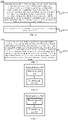
- FIG. 8 is a schematic structural diagram of a communication device 600 according to an embodiment of the present application.
- the communication device 600 shown in FIG 8 includes a processor 610.
- the processor 610 can call and execute a computer program from a memory to carry out the methods in the embodiments of the present application.
- the communication device 600 can further include a memory 620.
- the processor 610 can invoke and run the computer program from the memory 620 to carry out the methods in the embodiments of the present application.
- the memory 620 can be a separate device independent of the processor 610, or can be integrated in the processor 610.
- the communication device 600 can further include a transceiver 630, and the processor 610 can control the transceiver 630 to communicate with other devices, and specifically, to transmit information or data to other devices, or receive information or data transmitted from other devices.
- the transceiver 630 can include a transmitter and a receiver.
- the transceiver 630 can further include one or more antennas.
- the communication device 600 can specifically be a network device in the embodiments of the present application, and the communication device 600 can carry out the corresponding processes which are implemented by the network device in the methods of the embodiments of the present application, which will not be repeated here for the sake of brevity.
- the communication device 600 can specifically be a mobile terminal/terminal in the embodiments of the application, and the communication device 600 can implement the corresponding processes which are implemented by the mobile terminal/terminal in the methods according to the embodiments of the present application, which will not be repeated here for the sake of brevity.
- FIG. 9 is a schematic structural diagram of a chip according to an embodiment of the present application.
- the chip 700 shown in FIG 9 includes a processor 710 which can invoke and run a computer program from a memory to implement the methods in the embodiments of the present application.
- the chip 700 can further include a memory 720.
- the processor 710 can invoke and run the computer program from the memory 720 to implement the methods in the embodiments of the present application.
- the memory 720 can be a separate device independent of the processor 710, or can be integrated in the processor 710.
- the chip 700 can further include an input interface 730.
- the processor 710 can control the input interface 730 to communicate with other devices or chips, and particularly to obtain information or data transmitted by other devices or chips.
- the chip 700 can further include an output interface 740.
- the processor 710 can control the output interface 740 to communicate with other devices or chips, and particularly to output information or data to other devices or chips.
- the chip can be applied to the network device in the embodiments of the present application, and the chip can carry out the corresponding processes which are implemented by the network device in the methods of the embodiments of the present application, which will not be repeated here for the sake of brevity.
- the chip can be applied to the mobile terminal/terminal device in the embodiments of the present application, and the chip can implement the corresponding processed which are implemented by the mobile terminal/terminal device in the methods of the embodiments of the present application, which will not be repeated here for the sake of brevity.
- the chip mentioned in the embodiments of the present application can also be referred to as a system-level chip, a system chip, a chip system, or a system-on-chip.
- FIG. 10 is a schematic block diagram of a communication system 800 according to an embodiment of the present application. As shown in FIG 10 , the communication system 800 includes a terminal device 810 and a network device 820.
- the terminal device 810 can be used to implement the corresponding functions implemented by the terminal device in the above methods
- the network device 820 can be used to implement the corresponding functions implemented by the network device in the above methods, which will not be repeated here for the sake of brevity.
- the processor can be an integrated circuit chip with signal processing capability.
- the steps of the foregoing method embodiments can be performed by an integrated logic circuit of hardware in the processor or by instructions in a form of software.
- the foregoing processor can be a general-purpose processor, a Digital Signal Processor (DSP), an Application Specific Integrated Circuit (ASIC), a Field Programmable Gate Array (FPGA), another programmable logic device, discrete gate or transistor logic device, or a discrete hardware component, which can implement the methods, steps, and logical blocks disclosed in the embodiments of the present disclosure.
- the general-purpose processor can be a microprocessor, any conventional processor or the like.
- the steps of the methods disclosed in connection with the embodiments of the present disclosure can be directly embodied in and performed by a hardware decoding processor, or can be implemented by a combination of hardware and software modules in the decoding processor.
- the software modules can be located in a mature storage medium in the art such as a random access memory, a flash memory, a read-only memory, a programmable read-only memory, an electrically erasable programmable memory or a register.
- the storage medium is located in the memory, and the processor reads information in the memory and implements the steps of the above methods in combination with the hardware thereof.
- the memory in the embodiments of the present application may be a volatile memory or a non-volatile memory, or may include both the volatile and non-volatile memories.
- the non-volatile memory can be a Read-Only Memory (ROM), a Programmable ROM (PROM), an erasable PROM (EPROM), an electrically EPROM (EEPROM) or a flash memory.
- the volatile memory may be a Random Access Memory (RAM), which is used as an external cache.
- RAMs such as a Static RAM (SRAM), a Dynamic RAM (DRAM), a Synchronous DRAM (SDRAM), a Double Data Rate SDRAM (DDR SDRAM), an Enhanced SDRAM (ESDRAM), a Synchlink DRAM (SLDRAM)) and a Direct Rambus RAM (DR RAM).
- SRAM Static RAM
- DRAM Dynamic RAM
- SDRAM Synchronous DRAM
- DDR SDRAM Double Data Rate SDRAM
- ESDRAM Enhanced SDRAM
- SLDRAM Synchlink DRAM
- DR RAM Direct Rambus RAM
- the memory in the embodiments of the present disclosure can also be a Static RAM (SRAM), a Dynamic RAM (DRAM), a Synchronous DRAM (SDRAM), a Double Data Rate SDRAM (DDR SDRAM), an Enhanced SDRAM (ESDRAM), a Synch-Link DRAM (SLDRAM), a Direct Rambus RAM (DR RAM), among others. That is to say, the memory in the embodiments of the present disclosure is intended to include but is not limited to those and any other suitable types of memories.
- SRAM Static RAM
- DRAM Dynamic RAM
- SDRAM Synchronous DRAM
- DDR SDRAM Double Data Rate SDRAM
- ESDRAM Enhanced SDRAM
- SLDRAM Synch-Link DRAM
- DR RAM Direct Rambus RAM
- the embodiments of the present disclosure also provide a computer-readable storage medium for storing a computer program.
- the computer-readable storage medium can be applied to the network device in the embodiments of the present application, and the computer program causes a computer to perform the corresponding processes which are implemented by the network device in the methods of the embodiments of the present application, which will not be repeated here for the sake of brevity.
- the computer-readable storage medium can be applied to the mobile terminal/terminal device in the embodiments of the present application, and the computer program causes a computer to perform the corresponding processes which are implemented by the mobile terminal/terminal device in the methods of the embodiments of the present application, which will not be repeated here for the sake of brevity.
- the embodiments of the present application also provide a computer program product including computer program instructions.
- the computer program product can be applied to the network device in the embodiments of the present application, and the computer program instructions cause a computer to perform the corresponding processes implemented by the network device in the methods of the embodiments of the present application, which will not be repeated here for the sake of brevity.
- the computer program product can be applied to the mobile terminal/terminal device in the embodiments of the present application, and the computer program instructions cause a computer to perform the corresponding processes which are implemented by the mobile terminal/terminal device in the methods of the embodiments of the present application, which will not be repeated here for the sake of brevity.
- the embodiments of the application also provide a computer program.
- the computer program can be applied to the network device in the embodiments of the present application, and when running on a computer, the computer program causes the computer to perform the corresponding process implemented by the network device in the methods of the embodiments of the present application, which will not be repeated here for the sake of brevity.
- the computer program can be applied to the mobile terminal/terminal device in the embodiments of the present application, and when running on a computer, the computer program causes the computer to perform the corresponding processes implemented by the mobile terminal/terminal device in the methods of the embodiments of the present application, which will not be repeated here for the sake of brevity.
- the systems, devices, and methods disclosed in several embodiments of the present disclosure can be implemented in other manners.
- the device embodiments described above are merely illustrative.
- the division of the units is only a logical function division, and in actual implementations, there can be other division manners.
- a plurality of units or components can be combined or integrated into another system, or some features can be ignored or not implemented.
- the coupling or direct coupling or communication connection shown or discussed herein can also be indirect coupling or communication connection through some interfaces, devices or units, and can be in electrical, mechanical or other forms.
- the units described as separate components may be or may not be physically separated, and the components shown as units may be or may not be physical units, that is, they may be located in one place or may be distributed on multiple network units. Some or all of the units can be selected to achieve the objectives of the solutions of the embodiments according to actual requirements.
- the functional units in the embodiments of the present disclosure can be integrated into one processing unit, or each unit can individually exist physically, or two or more of the units can be integrated into one unit.
- the functions can be stored in a computer-readable storage medium.
- the technical solution of the present disclosure essentially, a part thereof that contributes to the prior art, or a part of the technical solution can be embodied in the form of a software product, and the computer software product is stored in a storage medium and includes instructions which enable a computer device (which may be a personal computer, a server, a network device or the like) to perform all or part of the steps of the methods described in the embodiments of the present disclosure.
- the foregoing storage medium includes various medium such as a USB drive, a removable hard disk, a ROM, a RAM, a magnetic disk or an optical disc that can store program codes.
Description
- This application relates to the field of communications, and in particular to a method for transmitting data and a terminal device.
- A Vehicle to Everything (V2X) system is a kind of sidelink (SL) transmission technology based on Long Term Evolution (LTE) Device to Device (D2D), and different from the traditional LTE system in which the communication data is received or sent through a base station, the V2X system adopts terminal-to-terminal direct communication, and thus has higher spectrum efficiency and lower transmission delay.
- In a NR system, different slot structures are supported in a cell, that is, one or more of downlink symbols, uplink symbols, and flexible symbols can be included in a slot, and the number of the symbols is configurable. The flexible symbol indicates an uncertain transmission direction, but the transmission direction can be changed through other configuration information or downlink control information. For example, a network device can configure a flexible symbol for sidelink transmission, or for uplink or downlink transmission.
- If a transmission resource is used for both the sidelink transmission and the uplink transmission, how to determine the data transmission on such resource is a problem to be solved. Related technologies are known from patent application publication
WO2018/082571A1 ; "UL/SL prioritization in eV2x", OPPO, 3GPP DRAFT, R2-1811092; and "Further Considerations on Uu/PC5 Prioritization", SAMSUNG, 3GPP DRAFT, R2-1701280. - The invention is defined by the independent claims. The embodiments of the present application provide a data transmission method and a terminal device, which can reasonably allocate resources when sidelink transmission conflicts with uplink or downlink transmission.
-
-
FIG. 1 is a schematic diagram of a communication system architecture according to an embodiment of the present application. -
FIG. 2 is a schematic diagram of a sidelink system according to an embodiment of the present application. -
FIG. 3 is a schematic diagram of a slot structure according to an embodiment of the present application. -
FIG. 4 is a schematic flowchart of a data transmission method according to an embodiment of the present application. -
FIG. 5 is a schematic flowchart of a data transmission method according to another embodiment of the present application. -
FIG. 6 is a schematic block diagram of a terminal device according to an embodiment of the present application. -
FIG. 7 is a schematic block diagram of another terminal device according to an embodiment of the present application. -
FIG. 8 is a schematic block diagram of a communication device according to an embodiment of the present application. -
FIG. 9 is a schematic block diagram of a chip according to an embodiment of the present application. -
FIG. 10 is a schematic block diagram of a communication system according to an embodiment of the present application. - The technical solutions in the embodiments of the present application will be described below in connection with the drawings in the embodiments of the present application. Obviously, the described embodiments are part of the embodiments of the present application, but not all the embodiments. Based on the embodiments in the present application, all other embodiments obtained by those of ordinary skill in the art without creative work fall within the protection scope of the present application.
- The technical solutions of the embodiments of the present application can be applied to various communication systems, such as a Global System of Mobile communication (GSM) system, a Code Division Multiple Access (CDMA) system, a Wideband Code Division Multiple Access (WCDMA) system, a General Packet Radio Service (GPRS), a Long Term Evolution (LTE) system, a LTE Frequency Division Duplex (FDD) system, a LTE Time Division Duplex (TDD) system, a Universal Mobile Telecommunication System (UMTS), a Worldwide Interoperability for Microwave Access (WiMAX) communication system, a 5G system, etc.
- For example, a communication system to which the embodiments of the present disclosure are applied is as shown in
FIG 1 . Thecommunication system 100 may include anetwork device 110 which may be a device that communicates with a terminal device 120 (or referred to as a communication terminal or a terminal). Thenetwork device 110 can provide communication coverage for a specific geographic area, and can communicate with terminal devices located in the coverage area. Optionally, thenetwork device 110 can be a Base Transceiver Station (BTS) in a GSM system or a CDMA system, a NodeB (NB) in a WCDMA system, an Evolutional Node B (eNB or eNodeB) in a LTE system, or a wireless controller in a Cloud Radio Access Network (CRAN). Optionally, the network device can be a mobile switching center, a relay station, an access point, an on-board device, a wearable device, a hub, a switch, a bridge, a router, a network side device in 5G network, a network device in future evolutional Public Land Mobile Network (PLMN), or the like. - The
communication system 100 also includes at least oneterminal device 120 located within the coverage range of thenetwork device 110. As used herein, the terminal device includes, but is not limited to, a device configured to receive/send communication signals and/or an Internet of Things (IoT) device, which may be connected with another device via wired lines, such as Public Switched Telephone Networks (PSTN), Digital Subscriber Line (DSL), digital cables, and direct cable connections; and/or via another data connection/network; and/or via a wireless interface, such as cellular networks, wireless local area networks (WLAN), digital TV networks such as DVB-H networks, satellite networks, AM-FM broadcast transmitter. A terminal device configured to communicate through a wireless interface may be referred to as a "wireless communication terminal", a "wireless terminal" or a "mobile terminal". Examples of the mobile terminal include but are not limited to satellite or cellular phones; Personal Communications System (PCS) terminals that can combine cellular radio phones with data processing, fax, and data communication capabilities; PDA that may include radio phones, pagers, Internet/intranet access, Web browser, memo pad, calendar, and/or Global Positioning System (GPS) receiver; and conventional laptop and/or palmtop receivers or other electronic devices including radio telephone transceivers. The terminal device may refer to access terminals, user equipment (LTE), user units, user stations, mobile stations, mobile sites, remote stations, remote terminals, mobile equipment, user terminals, terminals, wireless communication equipment, user agents, or user device. The access terminal may be a cellular phone, a cordless phone, a Session Initiation Protocol (SIP) phone, a wireless local loop (WLL) station, a personal digital assistant (PDA), and wireless communication functional handheld devices, computing devices or other processing devices connected to wireless modems, in-vehicle devices, wearable devices, terminal devices in 5G networks, terminal devices in the future evolution of PLMN, or the like. - Optionally, Device to Device (D2D) communication may be performed between the
terminal devices 120. - Optionally, the 5G system or 5G network may also be referred to as a New Radio (NR) system or NR network.
-
FIG. 1 exemplarily shows one network device and two terminal devices. Optionally, thecommunication system 100 may include multiple network devices and other numbers of terminal devices can be included in the coverage of each network device, which is not particularly limited in the embodiments of the present disclosure. - Optionally, the
communication system 100 may also include other network entities such as a network controller and a mobility management entity, which are not limited in the embodiments of the present application. - It should be understood that the device with a communication function in the network and/or system of the embodiments of the present disclosure may be referred to as the communication device. Taking the
communication system 100 shown inFIG 1 as an example, the communication device may include anetwork device 110 and aterminal device 120 which have the communication function. Thenetwork device 110 and theterminal device 120 may be the specific devices as described above, which will not be repeated here. The communication device may also include other devices in thecommunication system 100, such as a network controller, a mobility management entity, and other network entities, which are not limited in the embodiments of the present disclosure. - It should be understood that the terms "system" and "network" are often used interchangeably herein. The term "and/or" used herein is merely to describe relative relationships of relative objects, indicating that there can be three kinds of relationships. For example, A and/or B can indicate three cases where A exists alone, A and B exist simultaneously, or B exists alone. In addition, the character "/" used herein generally indicates that the related objects before and after this character are in an "or" relationship.
- The V2X technologies are standardized in 3GPP Release 14 (Rel-14), and two transmission modes are defined:
Mode 3 andMode 4.FIG 2 shows a schematic diagram of the two transmission modes in the V2X system according to an embodiment of the present application. - As shown in
FIG 2 , themode 3 on the left indicates that the transmission resources of an on-vehicle terminal are allocated by the base station through a downlink (DL), and the on-vehicle terminal transmits data on the sidelink according to the resources allocated by the base station. The base station can allocate resources for a single transmission for the terminal, or can allocate semi-static transmission resources for the terminal. - As shown in
FIG 2 , themode 4 on the right indicates that the on-vehicle terminal adopts a sensing and reservation transmission method. The on-vehicle terminal obtains a set of available transmission resources in a resource pool by sensing, and randomly selects a resource from the set for data transmission. Since the services in the V2X system have periodic characteristics, the terminal usually adopts the semi-static transmission method, that is, after selecting a transmission resource, the terminal will continue to use this resource in multiple transmission cycles so as to reduce resource reselection and the probability of resource conflicts. The terminal will carry information for reserving the resource for a next transmission in the control information of the current transmission, so that other terminals can determine whether such resource is reserved and used by the user by detecting the control information of the user, so as to achieve the purpose of reducing the resource conflicts. - In LTE-V2X, the sidelink transmission can be performed by using a dedicated carrier or a carrier shared with the uplink. When the shared carrier is used, the sidelink can only use uplink transmission resources, such as uplink sub-frames of a TDD system or an uplink carrier in a FDD system, and the sidelink cannot use downlink resources so as to avoid interference to the terminal.
- In the NR system, different slot structures are supported in a cell, that is, one or more of downlink symbols, uplink symbols, and flexible symbols can be included in a slot, and the number of various symbols is configurable. The flexible symbol indicates an uncertain transmission direction, but the transmission direction can be changed through other configuration information or downlink control information, for example, the flexible symbol can be changed to the downlink symbol or the uplink symbol through Downlink Control Information (DCI), or the transmission direction is implicitly determined by configuration information. For example, if the transmission of a Synchronization Signal Block (SSB) is configured on the flexible symbol, it can be determined that this symbol is for the downlink transmission.
- In the NR system, each slot can include 14 symbols or 7 symbols, one or more of the downlink symbol, the uplink symbol and the flexible symbol can be set in each slot, and the number of the symbols is configurable. For example,
FIG 3 shows a schematic diagram of a symbol distribution in the slot structure according to an embodiment of the present application. As shown inFIG 3 , the slot includes 14 symbols, and the downlink symbols, the flexible symbols and the uplink symbols are sequentially distributed chronologically in each slot. In the slot structure of Figure a, one slot includes 4 downlink symbols, 2 uplink symbols, and the rest are flexible symbols; in the slot structure of Figure b, one slot includes 7 downlink symbols, 4 uplink symbols, and the rest are flexible symbols, but the embodiments of the present application are not limited thereto. - In the NR-V2X system, the network device can configure the symbols in the slot to be used for the uplink transmission, the downlink transmission or the sidelink transmission. If a transmission resource is used for both the sidelink transmission and the uplink transmission, for example, the flexible symbols in a slot can be used for the sidelink transmission and the flexible symbols can also be configured for the uplink or downlink transmission, how to determine the data transmission on such resources is a problem to be solved. Therefore, according to an embodiment of the present application, there is proposed a data transmission method, which can avoid conflicts between the sidelink transmission and the uplink or downlink transmission.
-
FIG. 4 is a schematic flowchart of adata transmission method 200 according to an embodiment of the present application. Themethod 200 may be performed by a terminal device. For example, the terminal device may be the terminal device shown inFIG 1 or FIG 2 , which can perform uplink and downlink transmission with a network device, and can also perform sidelink transmission with other terminal devices. As shown inFIG 4 , themethod 200 includes: S210, determining, by the terminal device according to a first preset rule, a first type of transmission or a second type of transmission as a target type of transmission when the terminal device determines, according to first configuration information, to perform the first type of transmission on a target transmission resource and determines, according to second configuration information, to perform the second type of transmission on the target transmission resource, where the first type of transmission is sidelink transmission between the terminal device and other terminal devices, and the second type of transmission is uplink transmission or downlink transmission between the terminal device and a network device; and S220, performing data transmission with the target type of transmission on the target transmission resource. - It should be understood that prior to S210, the
method 200 further includes that determining, by the first terminal device according to the first configuration information, to perform the first type of transmission on the target transmission resource, the first type of transmission being the sidelink transmission between the terminal device and other terminal devices. In addition, themethod 200 further includes determining, by the terminal device according to the second configuration information, to perform the second type of transmission on the target transmission resource, the second type of transmission being the uplink or downlink transmission between the terminal device and the network device. That is, both the uplink or downlink transmission and the sidelink transmission are configured on the same target transmission resource, and resource conflicts may occur. - Optionally, the first configuration information may be configured by the network device for the terminal device, that is, the terminal device receives the first configuration information sent by the network device. Alternatively, the first configuration information may also be pre-configured information. For example, the first configuration information may be scheduling information or resource pool configuration information sent by the network device, and the terminal device determines to use the target resource for the sidelink transmission according to the first configuration information. For another example, the first configuration information may be pre-configured information, that is, specified in accordance with an agreement, or pre-stored on the terminal device.
- Optionally, the second configuration information may be configured by the network device for the terminal device, that is, the terminal device receives the second configuration information sent by the network device. For example, the second configuration information may be Radio Resource Control (RRC) configuration information or scheduling information, and the network device configures the terminal device to use the target resource for uplink data transmission through the second configuration information. For another example, the second configuration information may be broadcast information or RRC configuration information, and the network device configures the terminal device to use the target resource to transmit downlink data through the second configuration information.
- It should be understood that the target transmission resource in the embodiments of the present application may be a time-frequency resource, or a time-domain resource. Specifically, if the target transmission resource is the time domain resource, the terminal device determines, according to the first configuration information, to use the time domain resource for the first type of transmission, that is, the sidelink transmission, and at the same time, the terminal device determines, according to the second configuration information, to use the time domain resources for the second type of transmission, that is, the uplink or downlink transmission, and the frequency domain resources occupied by the sidelink transmission and the frequency domain resources occupied by the uplink or downlink transmission may be the same or different.
- For example, the target transmission resource is a time domain symbol, and the terminal device determines to transmit sidelink data on the time domain symbol according to the first configuration information, and determines to receive downlink data on the symbol according to the second configuration information. At this point, there will be conflicts on transmission directions.
- For another example, the target transmission resource may also be a specific time-frequency resource, and the terminal device determines to transmit sidelink data on this time-frequency resource according to the first configuration information, and determines to transmit uplink data on this time-frequency resource according to the second configuration information, and at this point, there is a transmission resource that is used for both the uplink transmission and the sidelink transmission, which will cause transmission resource conflicts.
- For still another example, the target transmission resource is a time domain symbol, and the terminal device determines to send sidelink data on a first frequency domain resource of the time domain symbol according to the first configuration information, and determines to send uplink data on a second frequency domain resource of the time domain symbol according to the second configuration information. The first frequency domain resource and the second frequency domain resource are different.
- In the embodiments of the present application, since the terminal device determines to perform the first type of transmission and the second type of transmission on the same target transmission resource according to the first configuration information and the second configuration information, the terminal device can determine the first type of transmission or the second type of transmission as the target type of transmission according to the first rule, where the first rule may be pre-configured, for example, it may be specified by an agreement, or the first rule may be configured by the network device for the terminal device, and the embodiments of the present application are not limited thereto.
- Optionally, as an embodiment, the first preset rule may be: determining the first type of transmission as the target type of transmission, or determining the second type of transmission as the target type of transmission. Specifically, the first rule may directly specify that the first type of transmission is preferentially performed or that the second type of transmission is preferentially performed. If the first rule specifies that the first type of transmission is preferentially performed, that is, the terminal device prioritizes the transmission of the sidelink data, the terminal device determines the first type of transmission as the target type of transmission, that is, the sidelink transmission is the target type of transmission, and the device performs the sidelink transmission on the target transmission resource, but does not perform the second type of transmission on the target transmission resource. If the first rule specifies that the second type of transmission is preferentially performed, that is, the terminal device prioritizes the transmission of the uplink or downlink data, the terminal device determines the second type of transmission as the target type of transmission, that is, the uplink or downlink transmission is the target type of transmission, and the terminal device performs the uplink or downlink transmission on the target transmission resource, and does not perform the sidelink transmission on the target transmission resource.
- Optionally, as an embodiment, the first preset rule may also be: determining the first type of transmission as the target type of transmission if a parameter information set of the first type of transmission meets a preset threshold. Correspondingly, if the parameter information set of the first type of transmission does not meet the preset threshold, the terminal device may determine the second type of transmission as the target type of transmission, or further determine whether to determine the second type of transmission as the target type of transmission or not in combination with other conditions. For example, if the parameter information set of the first type of transmission does not meet a first preset threshold, but the parameter information set of the second type of transmission meets a second preset threshold, the terminal device can determine the second type of transmission as the target type of transmission.
- Similarly, the first preset rule may also be: determining the second type of transmission as the target type of transmission if the parameter information set of the second type of transmission meets the second preset threshold. Correspondingly, if the parameter information set of the second type of transmission does not meet the second preset threshold, the terminal device may determine the first type of transmission as the target type of transmission, or determine whether to determine the first type of transmission as the target type of transmission or not in combination with other conditions. For example, if the parameter information set of the second type of transmission does not meet the second preset threshold, but the parameter information set of the first type of transmission meets the first preset threshold, the terminal device may determine the first type of transmission as the target type of transmission.
- Optionally, the parameter information set of the first type of transmission may be parameter information including information to be transmitted in the first type of transmission. For example, the terminal device may determine the parameter information set of the first type of transmission according to attribute information of a logical channel of the first type of transmission. Similarly, the parameter information set of the second type of transmission may also be parameter information including information to be transmitted in the second type of transmission. For example, the terminal device may determine the parameter information set of the second type of transmission based on the attribute information of the logical channel of the second type of transmission, and the embodiments of the present application are not limited thereto.
- It should be understood that the information to be transmitted in the first type of transmission may include data to be transmitted and/or feedback information to be transmitted, and similarly, the information to be transmitted in the second type of transmission may also include data to be transmitted and/or feedback information to be transmitted, and the embodiments of the present application are not limited thereto.
- The first type of transmission or the second type of transmission in the embodiments of the present application may include the transmission of a data channel and/or the transmission of a feedback channel (e.g., a physical control channel carrying retransmission feedback). For the data channel, the parameter information included in the parameter information set can be determined according to the attribute information of the logical channel corresponding to the data channel, such as a priority. For the feedback channel, the parameter information in the parameter information set can be determined according to attributes of the logical channel corresponding to a data channel corresponding to feedback information in the feedback channel.
- The parameter information set of the first type of transmission or the second type of transmission includes at least one of the following information: priority information, delay information, reliability information, transmission rate information, throughput information, Quality of Service (QoS) information and QoS Class Identifier (QCI) information. Moreover, the information included in the parameter information set of the first type of transmission may be the same as or different from the information included in the parameter information set of the second type of transmission.
- Optionally, based on one or more of the aforementioned priority information, delay information, reliability information, transmission rate information, throughput information, QoS information, and QCI information, the terminal device may also determine the remaining one or more information.
- Optionally, the first preset threshold or the second preset threshold may be configured by the network device, or may be pre-configured. For example, the terminal device may receive the first preset threshold sent by the network device, or the terminal device may obtain the second preset threshold according to the pre-configured information.
- In an embodiment of the present application, whether to determine the first type of transmission as the target type of transmission can be determined according to whether the first type of transmission meets the first preset value, or whether to determine the second type of transmission as the target type of transmission can be determined according to whether the second type of transmission meets the second preset value. For ease of description, the following description will be given in an example where whether to determine the first type of transmission as the target type of transmission is determined according to whether the first type of transmission meets the first preset value, but the same applies to the determining process for the second type of transmission. For example, it is also applicable by replacing the first type of transmission described below with the second type of transmission and replacing the first preset value with the second preset value.
- Specifically, when the parameter information set of the first type transmission includes multiple pieces of parameter information, the corresponding first preset threshold may also include multiple thresholds, and there is a corresponding first preset threshold corresponding to each piece of parameter information in the parameter information set. Due to the different parameter information in the parameter information set, the parameter information set meeting the first preset threshold may indicate that the parameter information in the parameter information set is greater than, or less than, or equal to the corresponding first preset threshold.
- For example, if the parameter information set of the first type of transmission includes the priority information, correspondingly, the first preset threshold includes a preset priority. For example, the parameter information set of the first type of transmission meeting the preset threshold may indicate that a priority of the sidelink transmission is higher than or equal to the preset priority, and the parameter information set not meeting the preset threshold may indicate that the priority of the sidelink transmission is lower than the preset priority or not equal to the preset priority.
- For another example, the parameter information set of the first type of transmission may also include delay information, and correspondingly, the first preset threshold includes a preset delay. For example, the parameter information set of the first type transmission meeting the preset threshold indicates that a length of a delay of the sidelink transmission is less than or equal to a length of the preset delay, and the parameter information set not meeting the preset threshold indicates that the length of the delay of the sidelink transmission is greater than the length of the preset delay or not equal to the length of the preset delay.
- For still another example, the parameter information set of the first type of transmission may also include reliability information, and correspondingly, the first preset threshold includes preset reliability. For example, the parameter information set of the first type of transmission meeting the preset threshold indicates that reliability of the sidelink transmission is greater than or equal to the preset reliability, and the parameter information set not meeting the preset threshold indicates that the reliability of the sidelink transmission is less than the preset reliability or not equal to the preset reliability.
- For still another example, the parameter information set of the first type of transmission may also include transmission rate information, and correspondingly, the first preset threshold includes a preset transmission rate. For example, the parameter information set of the first type of transmission meeting the preset threshold indicates that a transmission rate of the sidelink transmission is greater than or equal to the preset transmission rate, and the parameter information set not meeting the preset threshold indicates that the transmission rate of the sidelink transmission is less than the preset transmission rate or not equal to the preset transmission rate.
- For still another example, the parameter information set of the first type of transmission may also include throughput information, and correspondingly, the first preset threshold includes preset throughput. For example, the parameter information set of the first type of transmission meeting the preset threshold indicates that throughput of the sidelink transmission is greater than or equal to the preset throughput, and the parameter information set not meeting the preset threshold indicates that the throughput of the sidelink transmission is less than the preset throughput or not equal to the preset throughput.
- For still another example, the parameter information set of the first type of transmission may also include QoS information, and correspondingly, the first preset threshold includes preset QoS. For example, the parameter information set of the first type of transmission meeting the preset threshold indicates that QoS of the sidelink transmission is higher than or equal to the preset QoS, and the parameter information set not meeting the preset threshold indicates that the QoS of the sidelink transmission is lower than the preset QoS or not equal to the preset QoS.
- For still another example, the parameter information set of the first type of transmission may also include QCI information, and correspondingly, the first preset threshold includes preset QCI. For example, the parameter information set of the first type of transmission meeting the preset threshold indicates that QCI of the sidelink transmission is higher than or equal to the preset QCI, and the parameter information set not meeting the preset threshold indicates that the QCI of the sidelink transmission is lower than the preset QCI or not equal to the preset QCI.
- Optionally, the parameter information set of the first type of transmission may include multiple parameters, and when it is determined whether the parameter information set meets the first preset threshold, it may be determined in turn that each piece of parameter information meets the corresponding first preset threshold, and when all the parameter information meets the corresponding first preset thresholds, it is determined that the parameter information set meets the first preset threshold, otherwise, it is determined that the parameter information set does not meet the first preset threshold. Alternatively, it can only determine whether one or more piece of the parameter information meets the corresponding first preset threshold, when the one or more piece of the parameter information meets the corresponding first preset threshold, it is determined that the parameter information set meets the first preset threshold; otherwise, it is determined that the parameter information set does not meet the first preset threshold, and the embodiments of the present application are not limited thereto.
- In the embodiments of the present application, according to the first rule, when the parameter information set of the first type of transmission meets the preset threshold, it is determined that the first type of transmission is preferentially performed, that is, the terminal device preferentially transmits the sidelink data. For example, the terminal device determines the first type of transmission as the target type of transmission, that is, the sidelink transmission is the target type of transmission, and the terminal device performs the sidelink transmission on the target transmission resource and does not perform the second type of transmission on the target transmission resource. Alternatively, if part of the information to be transmitted in the first type of transmission meets the first preset threshold, the first type of transmission can be determined as the target type of transmission, and correspondingly, the data meeting the first preset threshold are preferentially transmitted on the target resource.
- Conversely, if the parameter information set of the first type of transmission does not meet the preset threshold, or part of the information to be transmitted in the first type of transmission does not meet the first preset threshold, the terminal device will not preferentially transmit this part of data. For example, the terminal device may further determine in combination with other conditions whether the second type of transmission can be preferentially transmitted, that is, whether to preferentially transmit uplink or downlink data. If the terminal device determines the second type of transmission as the target type of transmission, that is, the uplink or downlink transmission is the target type of transmission, the terminal device can perform the uplink or downlink transmission on the target transmission resource.
- Similarly, according to the first rule, when the parameter information set of the second type of transmission meets the preset threshold, the terminal device determines the second type of transmission as the target type of transmission, that is, the terminal device performs uplink or downlink transmission on the target transmission resource. For example, the terminal device determines the second type of transmission as the target type of transmission, that is, the uplink or downlink transmission is the target type of transmission, and the terminal device performs the uplink or downlink transmission on the target transmission resource, but does not perform the sidelink transmission on the target transmission resource. Alternatively, if part of the information to be transmitted in the second type of transmission meets the second preset threshold, the second type of transmission can be determined as the target type of transmission, and correspondingly, the data meeting the second preset threshold are transmitted on the target resource.
- Conversely, if the parameter information set of the second type of transmission does not meet the second preset threshold, or part of the information to be transmitted in the second type of transmission does not meet the second preset threshold, the terminal device will not preferentially transmit this part of data. For example, the terminal device may further determine in combination with other conditions whether the first type of transmission can be determined as the target type of transmission, that is, whether the terminal device performs the sidelink transmission on the target transmission resource. If the terminal device determines the first type of transmission as the target type of transmission, that is, the sidelink transmission is the target type of transmission, the terminal device can perform the sidelink transmission on the target transmission resource.
- Optionally, as another embodiment, the terminal device may also determine the first type of transmission or the second type of transmission as the target type of transmission according to a logical channel of the first type of transmission or a logical channel of the second type of transmission. Specifically, if the logical channel of the first type of transmission is a configured logical channel, the first type of transmission is determined as the target type of transmission, or if the logical channel of the second type of transmission is a configured logical channel, the second type of transmission is determined as the target type of transmission.
- It should be understood that determining whether the logical channel corresponding to the first type of transmission or the logical channel corresponding to the second type of transmission is the configured logical channel may include determining that the logical channel corresponding to the first type of transmission is the configured logical channel if the logical channel corresponding to the first type of transmission includes a specified configuration, and determining that the logical channel corresponding to the second type of transmission is the configured logical channel if the logical channel corresponding to the second type of transmission includes the specified configuration.
- Therefore, in the data transmission method according to the embodiments of the present application, when the terminal device determines that the sidelink transmission and the uplink or downlink transmission are performed on the same transmission resource according to the configuration information, conflicts may occur on the transmission resource, and the terminal device can select to preferentially perform the sidelink transmission or the uplink or downlink transmission on the transmission resource according to a certain rule so as to avoid conflicts.
- In the above, the data transmission method according to the embodiments of the present application is described in detail in connection with
FIG 4 from the perspective of the terminal device. Correspondingly, if the network device configures the terminal device with the same transmission resource on which the sidelink transmission can be performed and the uplink or downlink transmission can also be performed, the network device can also use the same method as the terminal device to determine which transmission is preferentially performed. For example, the network device can also perform the determination according to the above first rule, if it is determined to perform the uplink or downlink transmission, the network device can receive or send data from or to the terminal device on the transmission resource. Since the network device also needs to use the same rule as the terminal device to make the determination, the method is similar to themethod 200 described above, which will not be repeated here. - In the embodiments of the present application, if the terminal device determines to perform the sidelink transmission and the uplink transmission on the same time domain resource according to the configuration information, the terminal device can also select to simultaneously perform the sidelink transmission and the uplink transmission on different frequency domain resources in this time domain resource according to a certain rule, thereby avoiding conflicts. Therefore, according to an embodiment of the present application, there is proposed another data transmission method. Hereinafter, the data transmission method according to another embodiment of the present application will be described from the perspective of a terminal device with reference to
FIG 5 . -
FIG. 5 shows a schematic flowchart of adata transmission method 300 according to an embodiment of the present application. Themethod 300 may be performed by a terminal device. For example, the terminal device may be the terminal device shown inFIG. 1 or FIG 2 , which can perform uplink and downlink transmission with a network device, and can also perform sidelink transmission with other terminal devices. As shown inFIG 5 , themethod 300 includes: S310, performing, by the terminal device according to a preset rule, sidelink transmission on a target transmission resource with a first power and uplink transmission on the target transmission resource with a second power when the terminal device determines, according to first configuration information, to perform the sidelink transmission with other terminal devices on the target transmission resource, and determines, according to second configuration information, to perform the uplink transmission with a network device on the target transmission resource, where a sum of the first power and the second power is less than or equal to a maximum transmission power of the terminal device. - It should be understood that prior to S310, the
method 300 further includes that the first terminal device determines, according to the first configuration information, to perform sidelink transmission with other terminal devices on the target transmission resource. In addition, themethod 300 further includes that terminal device determines, according to the second configuration information, to perform uplink transmission with the network device on the target transmission resource, that is, the terminal device sends uplink data to the network device. That is to say, both the uplink transmission and the sidelink transmission are configured on the same target transmission resource, and resource conflicts will occur. - Optionally, the first configuration information may be configured by the network device for the terminal device, that is, the terminal device receives the first configuration information sent by the network device. Alternatively, the first configuration information may also be pre-configuration information. For example, the first configuration information may be scheduling information or resource pool configuration information sent by the network device, and the terminal device determines to use the target resource for the sidelink transmission according to the first configuration information. For another example, the first configuration information may be pre-configured information, that is, specified in accordance with an agreement, or pre-stored on the terminal device.
- Optionally, the second configuration information may be configured by the network device for the terminal device, that is, the terminal device receives the second configuration information sent by the network device. For example, the second configuration information may be Radio Resource Control (RRC) configuration information or scheduling information, and the network device configures the terminal device to use the target resource for the transmission of uplink data through the second configuration information.
- It should be understood that the target transmission resource in the embodiments of the present application may be a time-frequency resource, or a time domain resource. Specifically, if the target transmission resource is the time domain resource, the terminal device determines, according to the first configuration information, to use the time domain resource for the sidelink transmission, and at the same time, the terminal device determines, according to the second configuration information, to use the time domain resources for the uplink transmission, and the frequency domain resources occupied by the sidelink transmission and the frequency domain resources occupied by the uplink transmission may be the same or different.
- For example, the target transmission resource may be a specific time-frequency resource, and the terminal device determines to transmit sidelink data on this time-frequency resource according to the first configuration information, and determines to transmit uplink data on this time-frequency resource according to the second configuration information, and at this point, there is a transmission resource used for both the uplink transmission and the sidelink transmission, which will cause transmission resource conflicts.
- For another example, the target transmission resource is a time domain symbol, and the terminal device determines to send sidelink data on a first frequency domain resource of the time domain symbol according to the first configuration information, and determines to send uplink data on a second frequency domain resource of the time domain symbol according to the second configuration information. The first frequency domain resource and the second frequency domain resource are different.
- In the embodiments of the present application, since the terminal device determines to perform the sidelink transmission and the uplink transmission on the same target transmission resource according to the first configuration information and the second configuration information, the terminal device can allocate different transmission powers according to the preset rule, that is, the terminal device can use the first power for the sidelink transmission and the second power for the uplink transmission, where the sum of the first power and the second power is less than or equal to the maximum transmission power of the terminal device.
- It should be understood that the preset rule may be pre-configured, for example, specified by an agreement, or the preset rule may be configured by the network device for the terminal device, and the embodiments of the present application are not limited thereto.
- Optionally, the preset rule may include: allocating the first power and the second power according to a certain ratio. Specifically, the terminal device can determine whether to preferentially perform the sidelink transmission or the uplink transmission according to certain determination conditions. For example, the terminal device may determine an allocation ratio of the first power and the second power according to a parameter information set. If the parameter information set of the sidelink transmission meets a preset threshold, the first power of the sidelink transmission is prioritized when allocating the maximum transmission power so that the first power is closer to the requirements of the sidelink transmission, and then the second power of the terminal device for sending uplink data is adjusted based on the maximum transmission power. Conversely, if the parameter information set of the sidelink transmission does not meet the preset threshold, the second power for the uplink transmission can be prioritized when allocating the maximum transmission power so that the second power is closer to the requirements of the uplink transmission, and then the first power of the terminal device for the sidelink transmission is adjusted based on the maximum transmission power.
- Optionally, as an embodiment, the preset rule may be that if the parameter information set of the sidelink transmission meets the preset threshold, the first power meets the power requirement of the sidelink transmission and the second power is equal to a difference between the maximum transmission power and the first power, or the first power is equal to the maximum transmission power and the second power is zero. If the parameter information set of the sidelink transmission does not meet the preset threshold, the second power meets the power requirement of the uplink transmission and the first power is equal to a difference between the maximum transmission power and the second power, or the second power is equal to the maximum transmission power and the first power is zero.
- Specifically, the parameter information set in the embodiment of the present application includes at least one of the following information: priority information, delay information, reliability information, transmission rate information, throughput information, Quality of Service (QoS) information and QoS Class Identifier (QCI) information. Optionally, based on one or more of the aforementioned priority information, delay information, reliability information, transmission rate information, throughput information, QoS information, and QCI information, the terminal device may also determine the remaining one or more information.
- Optionally, the parameter information set of the sidelink transmission is a set of parameter information of data to be transmitted on the sidelink.
- Optionally, the preset threshold may be configured by the network device or may be pre-configured. For example, the terminal device may receive the preset threshold sent by the network device. Alternatively, the terminal device may also obtain the preset threshold according to the pre-configured information.
- When the parameter information set includes multiple pieces of parameter information, the corresponding preset threshold also includes multiple thresholds, and each parameter information in the parameter information set has a corresponding preset threshold. Due to different parameter information in the parameter information set, the parameter information set meeting the preset threshold may indicate that the parameter information in the parameter information set is greater than or less than the preset threshold.
- For example, if the parameter information set includes priority information, correspondingly, the preset threshold includes a preset priority. The parameter information set of the sidelink transmission meeting the preset threshold indicates that the priority of the sidelink transmission is higher than or equal to the preset priority, and the parameter information set of the sidelink transmission not meeting the preset threshold indicates that the priority of the sidelink transmission is lower than the preset priority.
- For another example, the parameter information set may also include delay information, and correspondingly, the preset threshold includes a preset delay. The parameter information set of the sidelink transmission meeting the preset threshold indicates that a length of a delay of the sidelink transmission is less than or equal to a length of the preset delay, and the parameter information set of the sidelink transmission not meeting the preset threshold indicates that the length of the delay of the sidelink transmission is greater than the length of the preset time delay.
- For still another example, the parameter information set may also include reliability information, and correspondingly, the preset threshold includes preset reliability. The parameter information set of the sidelink transmission meeting the preset threshold indicates that reliability of the sidelink transmission is greater than or equal to the preset reliability, and the parameter information set not meeting the preset threshold indicates that the reliability of the sidelink transmission is less than the preset reliability.
- For still another example, the parameter information set may also include transmission rate information, and correspondingly, the preset threshold includes a preset transmission rate. The parameter information set of the sidelink transmission meeting the preset threshold indicates that a transmission rate of the sidelink transmission is greater than or equal to the preset transmission rate, and the parameter information set not meeting the preset threshold indicates that the transmission rate of the sidelink transmission is less than the preset transmission rate.
- For still another example, the parameter information set may also include throughput information, and correspondingly, the preset threshold includes preset throughput. The parameter information set of the sidelink transmission meeting the preset threshold indicates that throughput of the sidelink transmission is greater than or equal to the preset throughput, and the parameter information set not meeting the preset threshold indicates that the throughput of the sidelink transmission is less than the preset throughput.
- For still another example, the parameter information set may also include QoS information, and correspondingly, the preset threshold includes preset QoS. The parameter information set of the sidelink transmission meeting the preset threshold indicates that QoS of the sidelink transmission is higher than or equal to the preset QoS, and the parameter information set not meeting the preset threshold indicates that the QoS of the sidelink transmission is lower than the preset QoS.
- For still another example, the parameter information set may also include QCI information, and correspondingly, the preset threshold includes preset QCI. The parameter information set of the sidelink transmission meeting the preset threshold indicates that QCI of the sidelink transmission is higher than or equal to the preset QCI, and the parameter information set not meeting the preset threshold indicates that the QCI of the sidelink transmission is lower than the preset QCI.
- Optionally, the parameter information set may include multiple parameters, and when it is determined whether the parameter information set meets the preset threshold, it may be determined in turn that each piece of parameter information meets the corresponding preset threshold, and when all the parameter information meets the corresponding preset thresholds, it is determined that the parameter information set meets the preset threshold, otherwise, it is determined that the parameter information set does not meet the preset threshold. Alternatively, it can only determine whether one or more piece of parameter information meets the corresponding preset threshold, and when the one or more piece of parameter information meets the corresponding preset threshold, it is determined that the parameter information set meets the preset threshold; otherwise, it is determined that the parameter information set does not meet the preset threshold, and the embodiments of the present application are not limited thereto.
- Optionally, if the parameter information set of the sidelink transmission meets the preset threshold, the transmission power for the sidelink data is guaranteed preferentially, that is, the power of the uplink transmission is adjusted so that the sum of the two powers is not greater than the maximum transmission power of the terminal, in other words, the first power meets the power requirement of the sidelink transmission, and then a difference between the maximum transmission power and the first power is determined as the second power. If the maximum transmission power is still not sufficient when the second power for the uplink transmission is adjusted to 0, that is, the first power is greater than the maximum transmission power, the first power may be set to the maximum transmission power, and the second power is set to zero.
- Optionally, if the parameter information set of the sidelink transmission does not meet the preset threshold, the transmission power for the uplink data is guaranteed preferentially, that is, the power of the sidelink transmission is adjusted so that the sum of the two powers is not greater than the maximum transmission power of the terminal, in other words, the second power meets the power requirement of the uplink transmission, and then a difference between the maximum transmission power and the second power is determined as the first power. If the maximum transmission power is still not sufficient when the first power for the sidelink transmission is adjusted to 0, that is, the second power is greater than the maximum transmission power, the second power may be set to the maximum transmission power, and the first power is set to zero.
- Optionally, in an embodiment, the terminal device simultaneously adjusts the first power and the second power according to a parameter, so that the sum of the adjusted first and second powers is less than or equal to the maximum transmission power.
- Therefore, in the data transmission method according to the embodiments of the present application, when the terminal device determines to perform sidelink transmission and uplink transmission on the same time domain resource according to the configuration information, the terminal device can allocate the transmission power according to a certain ratio, and perform the sidelink transmission and/or the uplink transmission in accordance with the respectively allocated powers, thereby avoiding conflicts.
- In the above, the data transmission method according to the embodiments of the present application is described in detail in connection with
FIG 5 from the perspective of the terminal device. Correspondingly, if the network device configures the terminal device with the same transmission resource on which the sidelink transmission can be performed and the uplink transmission can also be performed, the network device can also use the same method as the terminal device to determine the transmission manner of the terminal device. For example, the network device can also make the determination according to the above-mentioned preset rule, if it is determined to perform uplink transmission, the network device can receive the data sent by the terminal device on the corresponding transmission resource. Since the network device also needs to use the same rule as the terminal device to make the determination, the method is similar to themethod 300 described above, which will not be repeated here. - It should be understood that in the embodiments of the present application, the sequence number of the above-mentioned processes does not mean the performing order, and the performing order of the processes should be determined according to the functions and the internal logic thereof, and should not be limited in the implementations of the embodiments of the present application.
- In addition, the term "and/or" used herein is merely to describe relative relationships of relative objects, indicating that there can be three kinds of relationships. For example, A and/or B can indicate three cases where A exists alone, A and B exist simultaneously, or B exists alone. In addition, the character "/" used herein generally indicates that the related objects before and after this character are in an "or" relationship.
- The data transmission method according to the embodiments of the present application is described in detail above with reference to
FIGS. 1 to 5 , and the terminal device according to the embodiments of the present application will be described below with reference toFIGS. 6 to 10 . - As shown in
FIG 6 , theterminal device 400 according to an embodiment of the present application includes: a processing unit 410 and a transceiving unit 420. Specifically, the processing unit 410 is configured to determine, according to a first rule, a first type of transmission or a second type of transmission as a target type of transmission when it is determined, according to first configuration information, to perform the first type of transmission on a target transmission resource and it is determined, according to second configuration information, to perform the second type of transmission on the target transmission resource, where the first type of transmission is sidelink transmission between the terminal device and other terminal devices, and the second type of transmission is uplink transmission or downlink transmission between the terminal device and a network device. The transceiving unit 420 is configured to perform data transmission with the target type of transmission on the target transmission resource. - Optionally, as an embodiment, the target transmission resource is a time domain resource.
- Optionally, as an embodiment, the first rule is to determine the first type of transmission as the target type of transmission, or to determine the second type of transmission as the target type of transmission.
- Optionally, as an embodiment, the first rule is that if a parameter information set of the first type of transmission meets a first preset threshold, the first type of transmission is determined as the target type of transmission, and if the parameter information set of the first type of transmission does not meet the first preset threshold, the second type of transmission is determined as the target type of transmission.
- Optionally, as an embodiment, the transceiving unit 420 is further configured to receive the first preset threshold sent by the network device. Alternatively, the processing unit 410 is further configured to obtain the first preset threshold according to pre-configuration information.
- Optionally, as an embodiment, the first rule is that if the parameter information set of the second type of transmission meets a second preset threshold, the second type of transmission is determined as the target type of transmission.
- Optionally, as an embodiment, the processing unit 410 is further configured to determine the parameter information set of the second type of transmission according to attribute information of a logical channel of the second type of transmission.
- Optionally, as an embodiment, the transceiving unit 420 is further configured to receive the preset threshold sent by the network device. Alternatively, the processing unit 410 is further configured to obtain the preset threshold according to pre-configured information.
- Optionally, as an embodiment, the parameter information set includes at least one of the following information: priority information, delay information, reliability information, transmission rate information, throughput information, QoS information, and QCI information.
- Optionally, as an embodiment, the first rule is that if a logical channel of the first type of transmission is a configured logical channel, the first type of transmission is determined as the target type of transmission, or if a logical channel of the second type of transmission is the configured logical channel, and the second type of transmission is determined as the target type of transmission.
- Optionally, as an embodiment, the transceiving unit 420 is further configured to receive the first configuration information sent by the network device, or the processing unit 410 is further configured to obtain the first configuration information according to pre-configured information.
- Optionally, as an embodiment, the transceiving unit 420 is further configured to receive the second configuration information sent by the network device.
- Optionally, as an embodiment, the transceiving unit 420 is further configured to receive the first rule sent by the network device, or the processing unit 410 is further configured to obtain the first rule according to pre-configured information.
- It should be understood that the
terminal device 400 according to the embodiment of the present application may correspondingly perform themethod 200 in the embodiments of the present application, and the foregoing and other operations and/or functions of each unit in theterminal device 400 are to implement the corresponding process of the terminal device in the method ofFIG 4 , which will not be repeated here for the sake of brevity. - Therefore, according to the terminal device in the embodiments of the present application, when the terminal device determines to perform sidelink transmission and uplink transmission on the same time domain resource according to the configuration information, the terminal device can allocate the transmission power according to a certain ratio, and perform the sidelink transmission and/or the uplink transmission in accordance with the respectively allocated powers, thereby avoiding conflicts.
- As shown in
FIG 7 , theterminal device 500 according to an embodiment of the present application includes aprocessing unit 510 and a transceiving unit 520. Specifically, the transceiving unit 520 is configured to perform, according to a preset rule, sidelink transmission on a target transmission resource with a first power and uplink transmission on the target transmission resource with a second power when theprocessing unit 510 determines, according to first configuration information, to perform the sidelink transmission with other terminal devices on the target transmission resource, and determines, according to second configuration information, to perform the uplink transmission with a network device on the target transmission resource, where a sum of the first power and the second power is less than or equal to a maximum transmission power of the terminal device - Optionally, as an embodiment, the target transmission resource is a time domain resource, and the
processing unit 510 is further configured to determine, according to the first configuration information, to perform the sidelink transmission on a first frequency domain resource of the time domain resource, and determine, according to the second configuration information, to perform the uplink transmission on a second frequency domain resource of the time domain resource, where the first frequency domain resource is different from the second frequency domain resource. - Optionally, as an embodiment, the preset rule is that if a parameter information set of the sidelink transmission meets a preset threshold, the first power meets a power requirement of the sidelink transmission and the second power is equal to a difference between the maximum transmission power and the first power, or the first power is equal to the maximum transmission power and the second power is zero; and if the parameter information set of the sidelink transmission does not meet the preset threshold, the second power meets a power requirement of the uplink transmission and the first power is equal to a difference between the maximum transmission power and the second power, or the second power is equal to the maximum transmission power and the first power is zero.
- Optionally, as an embodiment, the parameter information set includes at least one of the following information: priority information, delay information, reliability information, transmission rate information, throughput information, quality of service (QoS) information, and QoS Class Identifier (QCI) information.
- Optionally, as an embodiment, the transceiving unit 520 is further configured to receive the preset threshold sent by the network device, or the
processing unit 510 is further configured to obtain the preset threshold according to pre-configured information. - It should be understood that the
terminal device 500 according to the embodiment of the present application may correspondingly perform themethod 300 in the embodiments of the present application, and the foregoing and other operations and/or functions of each unit in theterminal device 500 are to implement the corresponding process of the terminal device in the method ofFIG 5 , which will not be repeated here for the sake of brevity. - Therefore, according to the terminal device in the embodiments of the present application, when the terminal device determines to perform sidelink transmission and uplink transmission on the same time domain resource according to the configuration information, the terminal device can allocate the transmission power according to a certain ratio, and perform the sidelink transmission and/or the uplink transmission in accordance with the respectively allocated powers, thereby avoiding conflicts.
-
FIG. 8 is a schematic structural diagram of acommunication device 600 according to an embodiment of the present application. Thecommunication device 600 shown inFIG 8 includes aprocessor 610. Theprocessor 610 can call and execute a computer program from a memory to carry out the methods in the embodiments of the present application. - Optionally, as shown in
FIG 8 , thecommunication device 600 can further include amemory 620. Theprocessor 610 can invoke and run the computer program from thememory 620 to carry out the methods in the embodiments of the present application. - The
memory 620 can be a separate device independent of theprocessor 610, or can be integrated in theprocessor 610. - Optionally, as shown in
FIG 8 , thecommunication device 600 can further include atransceiver 630, and theprocessor 610 can control thetransceiver 630 to communicate with other devices, and specifically, to transmit information or data to other devices, or receive information or data transmitted from other devices. - The
transceiver 630 can include a transmitter and a receiver. Thetransceiver 630 can further include one or more antennas. - Optionally, the
communication device 600 can specifically be a network device in the embodiments of the present application, and thecommunication device 600 can carry out the corresponding processes which are implemented by the network device in the methods of the embodiments of the present application, which will not be repeated here for the sake of brevity. - Optionally, the
communication device 600 can specifically be a mobile terminal/terminal in the embodiments of the application, and thecommunication device 600 can implement the corresponding processes which are implemented by the mobile terminal/terminal in the methods according to the embodiments of the present application, which will not be repeated here for the sake of brevity. -
FIG. 9 is a schematic structural diagram of a chip according to an embodiment of the present application. Thechip 700 shown inFIG 9 includes aprocessor 710 which can invoke and run a computer program from a memory to implement the methods in the embodiments of the present application. - Optionally, as shown in
FIG 9 , thechip 700 can further include amemory 720. Theprocessor 710 can invoke and run the computer program from thememory 720 to implement the methods in the embodiments of the present application. - The
memory 720 can be a separate device independent of theprocessor 710, or can be integrated in theprocessor 710. - Optionally, the
chip 700 can further include aninput interface 730. Theprocessor 710 can control theinput interface 730 to communicate with other devices or chips, and particularly to obtain information or data transmitted by other devices or chips. - Optionally, the
chip 700 can further include anoutput interface 740. Theprocessor 710 can control theoutput interface 740 to communicate with other devices or chips, and particularly to output information or data to other devices or chips. - Optionally, the chip can be applied to the network device in the embodiments of the present application, and the chip can carry out the corresponding processes which are implemented by the network device in the methods of the embodiments of the present application, which will not be repeated here for the sake of brevity.
- Optionally, the chip can be applied to the mobile terminal/terminal device in the embodiments of the present application, and the chip can implement the corresponding processed which are implemented by the mobile terminal/terminal device in the methods of the embodiments of the present application, which will not be repeated here for the sake of brevity.
- It should be understood that the chip mentioned in the embodiments of the present application can also be referred to as a system-level chip, a system chip, a chip system, or a system-on-chip.
-
FIG. 10 is a schematic block diagram of acommunication system 800 according to an embodiment of the present application. As shown inFIG 10 , thecommunication system 800 includes aterminal device 810 and anetwork device 820. - The
terminal device 810 can be used to implement the corresponding functions implemented by the terminal device in the above methods, and thenetwork device 820 can be used to implement the corresponding functions implemented by the network device in the above methods, which will not be repeated here for the sake of brevity. - It should be understood that the processor according to the embodiments of the present application can be an integrated circuit chip with signal processing capability. In the implementations, the steps of the foregoing method embodiments can be performed by an integrated logic circuit of hardware in the processor or by instructions in a form of software. The foregoing processor can be a general-purpose processor, a Digital Signal Processor (DSP), an Application Specific Integrated Circuit (ASIC), a Field Programmable Gate Array (FPGA), another programmable logic device, discrete gate or transistor logic device, or a discrete hardware component, which can implement the methods, steps, and logical blocks disclosed in the embodiments of the present disclosure. The general-purpose processor can be a microprocessor, any conventional processor or the like. The steps of the methods disclosed in connection with the embodiments of the present disclosure can be directly embodied in and performed by a hardware decoding processor, or can be implemented by a combination of hardware and software modules in the decoding processor. The software modules can be located in a mature storage medium in the art such as a random access memory, a flash memory, a read-only memory, a programmable read-only memory, an electrically erasable programmable memory or a register. The storage medium is located in the memory, and the processor reads information in the memory and implements the steps of the above methods in combination with the hardware thereof.
- It can be understood that the memory in the embodiments of the present application may be a volatile memory or a non-volatile memory, or may include both the volatile and non-volatile memories. In an embodiment, the non-volatile memory can be a Read-Only Memory (ROM), a Programmable ROM (PROM), an erasable PROM (EPROM), an electrically EPROM (EEPROM) or a flash memory. The volatile memory may be a Random Access Memory (RAM), which is used as an external cache. By way of exemplary but not restrictive description, many forms of RAMs are available, such as a Static RAM (SRAM), a Dynamic RAM (DRAM), a Synchronous DRAM (SDRAM), a Double Data Rate SDRAM (DDR SDRAM), an Enhanced SDRAM (ESDRAM), a Synchlink DRAM (SLDRAM)) and a Direct Rambus RAM (DR RAM). It should be noted that the memories of the systems and methods described herein are intended to include, but are not limited to, these and any other suitable types of memories.
- It should be understood that the foregoing description of the memory is exemplary rather than limiting. For example, the memory in the embodiments of the present disclosure can also be a Static RAM (SRAM), a Dynamic RAM (DRAM), a Synchronous DRAM (SDRAM), a Double Data Rate SDRAM (DDR SDRAM), an Enhanced SDRAM (ESDRAM), a Synch-Link DRAM (SLDRAM), a Direct Rambus RAM (DR RAM), among others. That is to say, the memory in the embodiments of the present disclosure is intended to include but is not limited to those and any other suitable types of memories.
- The embodiments of the present disclosure also provide a computer-readable storage medium for storing a computer program.
- Optionally, the computer-readable storage medium can be applied to the network device in the embodiments of the present application, and the computer program causes a computer to perform the corresponding processes which are implemented by the network device in the methods of the embodiments of the present application, which will not be repeated here for the sake of brevity.
- Optionally, the computer-readable storage medium can be applied to the mobile terminal/terminal device in the embodiments of the present application, and the computer program causes a computer to perform the corresponding processes which are implemented by the mobile terminal/terminal device in the methods of the embodiments of the present application, which will not be repeated here for the sake of brevity.
- The embodiments of the present application also provide a computer program product including computer program instructions.
- Optionally, the computer program product can be applied to the network device in the embodiments of the present application, and the computer program instructions cause a computer to perform the corresponding processes implemented by the network device in the methods of the embodiments of the present application, which will not be repeated here for the sake of brevity.
- Optionally, the computer program product can be applied to the mobile terminal/terminal device in the embodiments of the present application, and the computer program instructions cause a computer to perform the corresponding processes which are implemented by the mobile terminal/terminal device in the methods of the embodiments of the present application, which will not be repeated here for the sake of brevity.
- The embodiments of the application also provide a computer program.
- Optionally, the computer program can be applied to the network device in the embodiments of the present application, and when running on a computer, the computer program causes the computer to perform the corresponding process implemented by the network device in the methods of the embodiments of the present application, which will not be repeated here for the sake of brevity.
- Optionally, the computer program can be applied to the mobile terminal/terminal device in the embodiments of the present application, and when running on a computer, the computer program causes the computer to perform the corresponding processes implemented by the mobile terminal/terminal device in the methods of the embodiments of the present application, which will not be repeated here for the sake of brevity.
- Those of ordinary skill in the art can recognize that the exemplary units and algorithm steps described in connection with the embodiments disclosed herein can be implemented in electronic hardware or a combination of computer software and the electronic hardware. Whether these functions are implemented in hardware or software depends on the specific applications of the technical solutions and design constraints. Various methods can be used by professional technicians to implement the described functions for each specific application, and such implementations should not be considered as going beyond the scope of the present disclosure.
- Those skilled in the art can clearly understand that for the convenience and conciseness of the description, for the specific operating process of the systems, devices and units described above, reference can be made to corresponding process in the foregoing method embodiments, which will not be repeated here.
- It should be understood that the systems, devices, and methods disclosed in several embodiments of the present disclosure can be implemented in other manners. For example, the device embodiments described above are merely illustrative. For example, the division of the units is only a logical function division, and in actual implementations, there can be other division manners. For example, a plurality of units or components can be combined or integrated into another system, or some features can be ignored or not implemented. In addition, the coupling or direct coupling or communication connection shown or discussed herein can also be indirect coupling or communication connection through some interfaces, devices or units, and can be in electrical, mechanical or other forms.
- The units described as separate components may be or may not be physically separated, and the components shown as units may be or may not be physical units, that is, they may be located in one place or may be distributed on multiple network units. Some or all of the units can be selected to achieve the objectives of the solutions of the embodiments according to actual requirements.
- In addition, the functional units in the embodiments of the present disclosure can be integrated into one processing unit, or each unit can individually exist physically, or two or more of the units can be integrated into one unit.
- If implemented in the form of software functional units and sold or used as an independent product, the functions can be stored in a computer-readable storage medium. Based on such understanding, the technical solution of the present disclosure essentially, a part thereof that contributes to the prior art, or a part of the technical solution can be embodied in the form of a software product, and the computer software product is stored in a storage medium and includes instructions which enable a computer device (which may be a personal computer, a server, a network device or the like) to perform all or part of the steps of the methods described in the embodiments of the present disclosure. The foregoing storage medium includes various medium such as a USB drive, a removable hard disk, a ROM, a RAM, a magnetic disk or an optical disc that can store program codes.
Claims (12)
- A data transmission method, comprising:determining (S210), by a terminal device according to a first rule, a first type of transmission or a second type of transmission as a target type of transmission when the terminal device determines, according to first configuration information, to perform the first type of transmission on a target transmission resource and determines, according to second configuration information, to perform the second type of transmission on the target transmission resource, wherein the first type of transmission is sidelink transmission between the terminal device and another terminal device, and the second type of transmission is uplink transmission or downlink transmission between the terminal device and a network device; andperforming (S220) data transmission with the target type of transmission on the target transmission resource,wherein the first rule comprises:determining the first type of transmission as the target type of transmission when priority information of the first type of transmission meets a first preset threshold; anddetermining the second type of transmission as the target type of transmission when the priority information of the first type of transmission does not meet the first preset threshold, andwherein the method is characterised in that:
when the first type of transmission or the second type of transmission comprises transmission of a feedback channel, determining priority information of the feedback channel according to an attribute of a logical channel corresponding to a data channel corresponding to feedback information in the feedback channel. - The method according to claim 1, wherein the target transmission resource is a time domain resource.
- The method according to claim 1, further comprising:receiving, by the terminal device, the first preset threshold sent by the network device; orobtaining, by the terminal device, the first preset threshold according to pre-configured information.
- The method according to claim 1 or 2, wherein the first rule comprises:
determining the second type of transmission as the target type of transmission when the priority information of the second type of transmission meets a second preset threshold. - The method according to claim 4, wherein the first rule further comprises:
determining the first type of transmission as the target type of transmission when the priority information of the second type of transmission does not meet the second preset threshold and the priority information of the first type of transmission meets the first preset threshold - The method according to claim 4 or 5, wherein the second preset threshold is pre-configured.
- The method according to claim 1 or 2, wherein the first rule comprises:
determining the second type of transmission as the target type of transmission when a logical channel corresponding to the second type of transmission is a configured logical channel. - The method according to any one of claims 1 to 7, further comprising:
receiving, by the terminal device, the first configuration information sent by the network device. - The method according to any one of claims 1 to 8, further comprising:
receiving, by the terminal device, the second configuration information sent by the network device. - The method according to any one of claims 1 to 9, further comprising:
obtaining, by the terminal device, the first rule according to pre-configured information. - A terminal device configured to perform the data transmission method according to any one of claims 1 to 10.
- A computer-readable storage medium for storing a computer program that causes a computer to perform the method according to any one of claims 1 to 10.
Priority Applications (1)
| Application Number | Priority Date | Filing Date | Title |
|---|---|---|---|
| EP22215260.5A EP4178302A1 (en) | 2018-11-01 | 2019-05-15 | Data transmission method and terminal device |
Applications Claiming Priority (2)
| Application Number | Priority Date | Filing Date | Title |
|---|---|---|---|
| PCT/CN2018/113444 WO2020087446A1 (en) | 2018-11-01 | 2018-11-01 | Data transmission method and terminal device |
| PCT/CN2019/087092 WO2020087908A1 (en) | 2018-11-01 | 2019-05-15 | Data transmission method and terminal device |
Related Child Applications (2)
| Application Number | Title | Priority Date | Filing Date |
|---|---|---|---|
| EP22215260.5A Division-Into EP4178302A1 (en) | 2018-11-01 | 2019-05-15 | Data transmission method and terminal device |
| EP22215260.5A Division EP4178302A1 (en) | 2018-11-01 | 2019-05-15 | Data transmission method and terminal device |
Publications (3)
| Publication Number | Publication Date |
|---|---|
| EP3863357A1 EP3863357A1 (en) | 2021-08-11 |
| EP3863357A4 EP3863357A4 (en) | 2021-12-22 |
| EP3863357B1 true EP3863357B1 (en) | 2023-01-25 |
Family
ID=70463606
Family Applications (2)
| Application Number | Title | Priority Date | Filing Date |
|---|---|---|---|
| EP22215260.5A Pending EP4178302A1 (en) | 2018-11-01 | 2019-05-15 | Data transmission method and terminal device |
| EP19879879.5A Active EP3863357B1 (en) | 2018-11-01 | 2019-05-15 | Data transmission method and terminal device |
Family Applications Before (1)
| Application Number | Title | Priority Date | Filing Date |
|---|---|---|---|
| EP22215260.5A Pending EP4178302A1 (en) | 2018-11-01 | 2019-05-15 | Data transmission method and terminal device |
Country Status (11)
| Country | Link |
|---|---|
| US (1) | US11246120B2 (en) |
| EP (2) | EP4178302A1 (en) |
| JP (1) | JP7428708B2 (en) |
| KR (1) | KR20210082467A (en) |
| CN (2) | CN112655269A (en) |
| AU (1) | AU2019370231A1 (en) |
| BR (1) | BR112021008157A2 (en) |
| CA (1) | CA3118240C (en) |
| MX (1) | MX2021005145A (en) |
| SG (1) | SG11202104225VA (en) |
| WO (2) | WO2020087446A1 (en) |
Families Citing this family (4)
| Publication number | Priority date | Publication date | Assignee | Title |
|---|---|---|---|---|
| CN111278126B (en) * | 2019-04-02 | 2023-01-20 | 维沃移动通信有限公司 | Resource allocation, resource allocation acquisition, information sending method and equipment |
| US20220191800A1 (en) * | 2019-04-06 | 2022-06-16 | Qualcomm Incorporated | Physical uplink shared channel transmit power configuration |
| US11871454B2 (en) * | 2019-07-19 | 2024-01-09 | Qualcomm Incorporated | Handling collisions between access link and sidelink |
| WO2023210836A1 (en) * | 2022-04-26 | 2023-11-02 | Sharp Kabushiki Kaisha | User equipments and methods |
Family Cites Families (16)
| Publication number | Priority date | Publication date | Assignee | Title |
|---|---|---|---|---|
| KR20080086384A (en) * | 2007-03-21 | 2008-09-25 | 한국전자통신연구원 | Mbms data transmission and receiving in packet based on mobile communication system |
| KR20170057227A (en) * | 2014-09-23 | 2017-05-24 | 엘지전자 주식회사 | Method for priority handling for buffer status reporting in a d2d communication system and device therefor |
| US10616909B2 (en) * | 2015-08-12 | 2020-04-07 | Lg Electronics Inc. | D2D operation method performed by means of terminal in wireless communication system and terminal using same |
| JP6678743B2 (en) * | 2016-03-18 | 2020-04-08 | オッポ広東移動通信有限公司Guangdong Oppo Mobile Telecommunications Corp., Ltd. | Communication method, terminal device and network device |
| CN107318086B (en) * | 2016-04-26 | 2020-03-20 | 华为技术有限公司 | Method and device for allocating time-frequency resources |
| CN107371182A (en) * | 2016-05-13 | 2017-11-21 | 展讯通信(上海)有限公司 | User equipment and its data transmission method |
| US20180019794A1 (en) * | 2016-07-14 | 2018-01-18 | Sharp Laboratories Of America, Inc. | Systems and methods for downlink control information for multiple-user superposition transmission |
| KR102469627B1 (en) * | 2016-10-20 | 2022-11-22 | 엘지전자 주식회사 | Method and apparatus for performing sidelink transmission prior to uplink transmission in wireless communication system |
| WO2018082571A1 (en) * | 2016-11-04 | 2018-05-11 | Telefonaktiebolaget Lm Ericsson (Publ) | Methods and apparatuses for transmission scheduling in a wireless communication system |
| KR102582554B1 (en) * | 2017-01-03 | 2023-09-25 | 삼성전자 주식회사 | The method of supporting the light connection in the next generation mobile communication systems |
| CN108282278B (en) * | 2017-01-05 | 2021-02-05 | 华为技术有限公司 | Data transmission method, terminal equipment and network equipment |
| CN108307419B (en) * | 2017-01-12 | 2021-09-03 | 华为技术有限公司 | Authorization-free transmission method, terminal equipment and network equipment |
| CN108322414B (en) * | 2017-01-17 | 2023-01-13 | 华为技术有限公司 | Feedback information transmission method and device |
| CN108347313B (en) * | 2017-01-24 | 2021-08-13 | 华为技术有限公司 | Feedback method and user equipment |
| US11159979B2 (en) * | 2017-04-26 | 2021-10-26 | Asustek Computer Inc. | Method and apparatus for requesting resource for control element transmission in a wireless communication system |
| WO2020033513A1 (en) * | 2018-08-07 | 2020-02-13 | Idac Holdings, Inc. | Control information transmission and sensing in wireless systems |
-
2018
- 2018-11-01 WO PCT/CN2018/113444 patent/WO2020087446A1/en active Application Filing
-
2019
- 2019-05-15 CN CN201980058275.1A patent/CN112655269A/en active Pending
- 2019-05-15 KR KR1020217013903A patent/KR20210082467A/en unknown
- 2019-05-15 EP EP22215260.5A patent/EP4178302A1/en active Pending
- 2019-05-15 CA CA3118240A patent/CA3118240C/en active Active
- 2019-05-15 BR BR112021008157-7A patent/BR112021008157A2/en unknown
- 2019-05-15 AU AU2019370231A patent/AU2019370231A1/en active Pending
- 2019-05-15 CN CN202110430477.3A patent/CN113225823B/en active Active
- 2019-05-15 EP EP19879879.5A patent/EP3863357B1/en active Active
- 2019-05-15 WO PCT/CN2019/087092 patent/WO2020087908A1/en unknown
- 2019-05-15 JP JP2021523390A patent/JP7428708B2/en active Active
- 2019-05-15 SG SG11202104225VA patent/SG11202104225VA/en unknown
- 2019-05-15 MX MX2021005145A patent/MX2021005145A/en unknown
-
2021
- 2021-04-26 US US17/240,869 patent/US11246120B2/en active Active
Also Published As
| Publication number | Publication date |
|---|---|
| CA3118240C (en) | 2023-08-22 |
| AU2019370231A1 (en) | 2021-06-03 |
| KR20210082467A (en) | 2021-07-05 |
| BR112021008157A2 (en) | 2021-08-03 |
| CN112655269A (en) | 2021-04-13 |
| CN113225823A (en) | 2021-08-06 |
| WO2020087908A1 (en) | 2020-05-07 |
| MX2021005145A (en) | 2021-07-15 |
| EP4178302A1 (en) | 2023-05-10 |
| US20220124696A1 (en) | 2022-04-21 |
| CN113225823B (en) | 2022-12-06 |
| CA3118240A1 (en) | 2020-05-07 |
| EP3863357A4 (en) | 2021-12-22 |
| US20210250934A1 (en) | 2021-08-12 |
| EP3863357A1 (en) | 2021-08-11 |
| US11246120B2 (en) | 2022-02-08 |
| JP7428708B2 (en) | 2024-02-06 |
| WO2020087446A1 (en) | 2020-05-07 |
| JP2022506187A (en) | 2022-01-17 |
| SG11202104225VA (en) | 2021-05-28 |
Similar Documents
| Publication | Publication Date | Title |
|---|---|---|
| EP3863357B1 (en) | Data transmission method and terminal device | |
| WO2021073495A1 (en) | Method and device for sharing channel occupancy time, terminal device, and network device | |
| EP3852461B1 (en) | Resource allocation method and terminal | |
| WO2021026891A1 (en) | Method for transmitting sidelink data, terminal device, and network device | |
| US20220046632A1 (en) | Communication method in d2d system, terminal device, and network device | |
| US20220368454A1 (en) | Method for Determining Transmission Mode in Sidelink, Terminal Apparatus, and Network Apparatus | |
| WO2021007779A1 (en) | Resource sharing method and apparatus, and terminal device | |
| WO2020001623A1 (en) | Method for determining sidelink category, terminal device, and network device | |
| EP3860274A1 (en) | Wireless communication method and device | |
| WO2020051919A1 (en) | Methods and apparatuses for determining and allocating resources, and terminal and network device | |
| WO2020034163A1 (en) | Uplink signal transmission method, terminal and storage medium | |
| US20210235423A1 (en) | Access control method, terminal, and storage medium | |
| US11963173B2 (en) | Data transmission method and terminal device | |
| CN112655162A (en) | Method, apparatus and program for determining number of uplink control information transmission resources | |
| WO2021164544A1 (en) | Communication method and apparatus, ue and network device | |
| US11956666B2 (en) | HARQ process determination method, network device and terminal | |
| EP3902350B1 (en) | Resource pool configuration method, device, and storage medium | |
| WO2023133902A1 (en) | Wireless communication methods and apparatuses, terminal device, and network device | |
| EP3873156A1 (en) | Data transmission method and apparatus, and network device and terminal | |
| CN113545126A (en) | Link transmission method, terminal equipment and storage medium |
Legal Events
| Date | Code | Title | Description |
|---|---|---|---|
| STAA | Information on the status of an ep patent application or granted ep patent |
Free format text: STATUS: THE INTERNATIONAL PUBLICATION HAS BEEN MADE |
|
| PUAI | Public reference made under article 153(3) epc to a published international application that has entered the european phase |
Free format text: ORIGINAL CODE: 0009012 |
|
| STAA | Information on the status of an ep patent application or granted ep patent |
Free format text: STATUS: REQUEST FOR EXAMINATION WAS MADE |
|
| 17P | Request for examination filed |
Effective date: 20210504 |
|
| AK | Designated contracting states |
Kind code of ref document: A1 Designated state(s): AL AT BE BG CH CY CZ DE DK EE ES FI FR GB GR HR HU IE IS IT LI LT LU LV MC MK MT NL NO PL PT RO RS SE SI SK SM TR |
|
| A4 | Supplementary search report drawn up and despatched |
Effective date: 20211124 |
|
| RIC1 | Information provided on ipc code assigned before grant |
Ipc: H04W 72/02 20090101ALN20211118BHEP Ipc: H04W 52/26 20090101ALN20211118BHEP Ipc: H04W 52/38 20090101ALI20211118BHEP Ipc: H04W 52/36 20090101ALI20211118BHEP Ipc: H04W 72/12 20090101AFI20211118BHEP |
|
| DAV | Request for validation of the european patent (deleted) | ||
| DAX | Request for extension of the european patent (deleted) | ||
| GRAP | Despatch of communication of intention to grant a patent |
Free format text: ORIGINAL CODE: EPIDOSNIGR1 |
|
| STAA | Information on the status of an ep patent application or granted ep patent |
Free format text: STATUS: GRANT OF PATENT IS INTENDED |
|
| RIC1 | Information provided on ipc code assigned before grant |
Ipc: H04W 72/02 20090101ALN20220801BHEP Ipc: H04W 52/26 20090101ALN20220801BHEP Ipc: H04W 52/38 20090101ALI20220801BHEP Ipc: H04W 52/36 20090101ALI20220801BHEP Ipc: H04W 72/12 20090101AFI20220801BHEP |
|
| INTG | Intention to grant announced |
Effective date: 20220906 |
|
| GRAS | Grant fee paid |
Free format text: ORIGINAL CODE: EPIDOSNIGR3 |
|
| GRAA | (expected) grant |
Free format text: ORIGINAL CODE: 0009210 |
|
| STAA | Information on the status of an ep patent application or granted ep patent |
Free format text: STATUS: THE PATENT HAS BEEN GRANTED |
|
| AK | Designated contracting states |
Kind code of ref document: B1 Designated state(s): AL AT BE BG CH CY CZ DE DK EE ES FI FR GB GR HR HU IE IS IT LI LT LU LV MC MK MT NL NO PL PT RO RS SE SI SK SM TR |
|
| REG | Reference to a national code |
Ref country code: GB Ref legal event code: FG4D |
|
| REG | Reference to a national code |
Ref country code: CH Ref legal event code: EP |
|
| REG | Reference to a national code |
Ref country code: DE Ref legal event code: R096 Ref document number: 602019024954 Country of ref document: DE |
|
| REG | Reference to a national code |
Ref country code: AT Ref legal event code: REF Ref document number: 1546645 Country of ref document: AT Kind code of ref document: T Effective date: 20230215 Ref country code: IE Ref legal event code: FG4D |
|
| REG | Reference to a national code |
Ref country code: LT Ref legal event code: MG9D |
|
| REG | Reference to a national code |
Ref country code: NL Ref legal event code: MP Effective date: 20230125 |
|
| P01 | Opt-out of the competence of the unified patent court (upc) registered |
Effective date: 20230412 |
|
| REG | Reference to a national code |
Ref country code: AT Ref legal event code: MK05 Ref document number: 1546645 Country of ref document: AT Kind code of ref document: T Effective date: 20230125 |
|
| PG25 | Lapsed in a contracting state [announced via postgrant information from national office to epo] |
Ref country code: NL Free format text: LAPSE BECAUSE OF FAILURE TO SUBMIT A TRANSLATION OF THE DESCRIPTION OR TO PAY THE FEE WITHIN THE PRESCRIBED TIME-LIMIT Effective date: 20230125 |
|
| PG25 | Lapsed in a contracting state [announced via postgrant information from national office to epo] |
Ref country code: RS Free format text: LAPSE BECAUSE OF FAILURE TO SUBMIT A TRANSLATION OF THE DESCRIPTION OR TO PAY THE FEE WITHIN THE PRESCRIBED TIME-LIMIT Effective date: 20230125 Ref country code: PT Free format text: LAPSE BECAUSE OF FAILURE TO SUBMIT A TRANSLATION OF THE DESCRIPTION OR TO PAY THE FEE WITHIN THE PRESCRIBED TIME-LIMIT Effective date: 20230525 Ref country code: NO Free format text: LAPSE BECAUSE OF FAILURE TO SUBMIT A TRANSLATION OF THE DESCRIPTION OR TO PAY THE FEE WITHIN THE PRESCRIBED TIME-LIMIT Effective date: 20230425 Ref country code: LV Free format text: LAPSE BECAUSE OF FAILURE TO SUBMIT A TRANSLATION OF THE DESCRIPTION OR TO PAY THE FEE WITHIN THE PRESCRIBED TIME-LIMIT Effective date: 20230125 Ref country code: LT Free format text: LAPSE BECAUSE OF FAILURE TO SUBMIT A TRANSLATION OF THE DESCRIPTION OR TO PAY THE FEE WITHIN THE PRESCRIBED TIME-LIMIT Effective date: 20230125 Ref country code: HR Free format text: LAPSE BECAUSE OF FAILURE TO SUBMIT A TRANSLATION OF THE DESCRIPTION OR TO PAY THE FEE WITHIN THE PRESCRIBED TIME-LIMIT Effective date: 20230125 Ref country code: ES Free format text: LAPSE BECAUSE OF FAILURE TO SUBMIT A TRANSLATION OF THE DESCRIPTION OR TO PAY THE FEE WITHIN THE PRESCRIBED TIME-LIMIT Effective date: 20230125 Ref country code: AT Free format text: LAPSE BECAUSE OF FAILURE TO SUBMIT A TRANSLATION OF THE DESCRIPTION OR TO PAY THE FEE WITHIN THE PRESCRIBED TIME-LIMIT Effective date: 20230125 |
|
| PGFP | Annual fee paid to national office [announced via postgrant information from national office to epo] |
Ref country code: FR Payment date: 20230525 Year of fee payment: 5 Ref country code: DE Payment date: 20230524 Year of fee payment: 5 |
|
| PG25 | Lapsed in a contracting state [announced via postgrant information from national office to epo] |
Ref country code: SE Free format text: LAPSE BECAUSE OF FAILURE TO SUBMIT A TRANSLATION OF THE DESCRIPTION OR TO PAY THE FEE WITHIN THE PRESCRIBED TIME-LIMIT Effective date: 20230125 Ref country code: PL Free format text: LAPSE BECAUSE OF FAILURE TO SUBMIT A TRANSLATION OF THE DESCRIPTION OR TO PAY THE FEE WITHIN THE PRESCRIBED TIME-LIMIT Effective date: 20230125 Ref country code: IS Free format text: LAPSE BECAUSE OF FAILURE TO SUBMIT A TRANSLATION OF THE DESCRIPTION OR TO PAY THE FEE WITHIN THE PRESCRIBED TIME-LIMIT Effective date: 20230525 Ref country code: GR Free format text: LAPSE BECAUSE OF FAILURE TO SUBMIT A TRANSLATION OF THE DESCRIPTION OR TO PAY THE FEE WITHIN THE PRESCRIBED TIME-LIMIT Effective date: 20230426 Ref country code: FI Free format text: LAPSE BECAUSE OF FAILURE TO SUBMIT A TRANSLATION OF THE DESCRIPTION OR TO PAY THE FEE WITHIN THE PRESCRIBED TIME-LIMIT Effective date: 20230125 |
|
| REG | Reference to a national code |
Ref country code: DE Ref legal event code: R097 Ref document number: 602019024954 Country of ref document: DE |
|
| PG25 | Lapsed in a contracting state [announced via postgrant information from national office to epo] |
Ref country code: SM Free format text: LAPSE BECAUSE OF FAILURE TO SUBMIT A TRANSLATION OF THE DESCRIPTION OR TO PAY THE FEE WITHIN THE PRESCRIBED TIME-LIMIT Effective date: 20230125 Ref country code: RO Free format text: LAPSE BECAUSE OF FAILURE TO SUBMIT A TRANSLATION OF THE DESCRIPTION OR TO PAY THE FEE WITHIN THE PRESCRIBED TIME-LIMIT Effective date: 20230125 Ref country code: EE Free format text: LAPSE BECAUSE OF FAILURE TO SUBMIT A TRANSLATION OF THE DESCRIPTION OR TO PAY THE FEE WITHIN THE PRESCRIBED TIME-LIMIT Effective date: 20230125 Ref country code: DK Free format text: LAPSE BECAUSE OF FAILURE TO SUBMIT A TRANSLATION OF THE DESCRIPTION OR TO PAY THE FEE WITHIN THE PRESCRIBED TIME-LIMIT Effective date: 20230125 Ref country code: CZ Free format text: LAPSE BECAUSE OF FAILURE TO SUBMIT A TRANSLATION OF THE DESCRIPTION OR TO PAY THE FEE WITHIN THE PRESCRIBED TIME-LIMIT Effective date: 20230125 |
|
| PGFP | Annual fee paid to national office [announced via postgrant information from national office to epo] |
Ref country code: GB Payment date: 20230525 Year of fee payment: 5 |
|
| PG25 | Lapsed in a contracting state [announced via postgrant information from national office to epo] |
Ref country code: SK Free format text: LAPSE BECAUSE OF FAILURE TO SUBMIT A TRANSLATION OF THE DESCRIPTION OR TO PAY THE FEE WITHIN THE PRESCRIBED TIME-LIMIT Effective date: 20230125 |
|
| PLBE | No opposition filed within time limit |
Free format text: ORIGINAL CODE: 0009261 |
|
| STAA | Information on the status of an ep patent application or granted ep patent |
Free format text: STATUS: NO OPPOSITION FILED WITHIN TIME LIMIT |
|
| REG | Reference to a national code |
Ref country code: CH Ref legal event code: PL |
|
| 26N | No opposition filed |
Effective date: 20231026 |
|
| PG25 | Lapsed in a contracting state [announced via postgrant information from national office to epo] |
Ref country code: MC Free format text: LAPSE BECAUSE OF FAILURE TO SUBMIT A TRANSLATION OF THE DESCRIPTION OR TO PAY THE FEE WITHIN THE PRESCRIBED TIME-LIMIT Effective date: 20230125 |
|
| REG | Reference to a national code |
Ref country code: BE Ref legal event code: MM Effective date: 20230531 |
|
| PG25 | Lapsed in a contracting state [announced via postgrant information from national office to epo] |
Ref country code: SI Free format text: LAPSE BECAUSE OF FAILURE TO SUBMIT A TRANSLATION OF THE DESCRIPTION OR TO PAY THE FEE WITHIN THE PRESCRIBED TIME-LIMIT Effective date: 20230125 Ref country code: MC Free format text: LAPSE BECAUSE OF FAILURE TO SUBMIT A TRANSLATION OF THE DESCRIPTION OR TO PAY THE FEE WITHIN THE PRESCRIBED TIME-LIMIT Effective date: 20230125 Ref country code: LU Free format text: LAPSE BECAUSE OF NON-PAYMENT OF DUE FEES Effective date: 20230515 Ref country code: LI Free format text: LAPSE BECAUSE OF NON-PAYMENT OF DUE FEES Effective date: 20230531 Ref country code: CH Free format text: LAPSE BECAUSE OF NON-PAYMENT OF DUE FEES Effective date: 20230531 |
|
| REG | Reference to a national code |
Ref country code: IE Ref legal event code: MM4A |