EP3863266A1 - Information terminal - Google Patents
Information terminal Download PDFInfo
- Publication number
- EP3863266A1 EP3863266A1 EP21154011.7A EP21154011A EP3863266A1 EP 3863266 A1 EP3863266 A1 EP 3863266A1 EP 21154011 A EP21154011 A EP 21154011A EP 3863266 A1 EP3863266 A1 EP 3863266A1
- Authority
- EP
- European Patent Office
- Prior art keywords
- section
- expansion
- case
- cover
- main body
- Prior art date
- Legal status (The legal status is an assumption and is not a legal conclusion. Google has not performed a legal analysis and makes no representation as to the accuracy of the status listed.)
- Granted
Links
Images








Classifications
-
- H—ELECTRICITY
- H04—ELECTRIC COMMUNICATION TECHNIQUE
- H04M—TELEPHONIC COMMUNICATION
- H04M1/00—Substation equipment, e.g. for use by subscribers
- H04M1/02—Constructional features of telephone sets
- H04M1/0202—Portable telephone sets, e.g. cordless phones, mobile phones or bar type handsets
- H04M1/026—Details of the structure or mounting of specific components
- H04M1/0274—Details of the structure or mounting of specific components for an electrical connector module
-
- G—PHYSICS
- G06—COMPUTING OR CALCULATING; COUNTING
- G06F—ELECTRIC DIGITAL DATA PROCESSING
- G06F1/00—Details not covered by groups G06F3/00 - G06F13/00 and G06F21/00
- G06F1/16—Constructional details or arrangements
- G06F1/1613—Constructional details or arrangements for portable computers
- G06F1/1626—Constructional details or arrangements for portable computers with a single-body enclosure integrating a flat display, e.g. Personal Digital Assistants [PDAs]
-
- G—PHYSICS
- G06—COMPUTING OR CALCULATING; COUNTING
- G06F—ELECTRIC DIGITAL DATA PROCESSING
- G06F1/00—Details not covered by groups G06F3/00 - G06F13/00 and G06F21/00
- G06F1/16—Constructional details or arrangements
- G06F1/1613—Constructional details or arrangements for portable computers
- G06F1/163—Wearable computers, e.g. on a belt
-
- G—PHYSICS
- G06—COMPUTING OR CALCULATING; COUNTING
- G06F—ELECTRIC DIGITAL DATA PROCESSING
- G06F1/00—Details not covered by groups G06F3/00 - G06F13/00 and G06F21/00
- G06F1/16—Constructional details or arrangements
- G06F1/1613—Constructional details or arrangements for portable computers
- G06F1/1632—External expansion units, e.g. docking stations
-
- G—PHYSICS
- G06—COMPUTING OR CALCULATING; COUNTING
- G06F—ELECTRIC DIGITAL DATA PROCESSING
- G06F1/00—Details not covered by groups G06F3/00 - G06F13/00 and G06F21/00
- G06F1/16—Constructional details or arrangements
- G06F1/1613—Constructional details or arrangements for portable computers
- G06F1/1633—Constructional details or arrangements of portable computers not specific to the type of enclosures covered by groups G06F1/1615 - G06F1/1626
- G06F1/1656—Details related to functional adaptations of the enclosure, e.g. to provide protection against EMI, shock, water, or to host detachable peripherals like a mouse or removable expansions units like PCMCIA cards, or to provide access to internal components for maintenance or to removable storage supports like CDs or DVDs, or to mechanically mount accessories
-
- G—PHYSICS
- G06—COMPUTING OR CALCULATING; COUNTING
- G06F—ELECTRIC DIGITAL DATA PROCESSING
- G06F1/00—Details not covered by groups G06F3/00 - G06F13/00 and G06F21/00
- G06F1/16—Constructional details or arrangements
- G06F1/1613—Constructional details or arrangements for portable computers
- G06F1/1633—Constructional details or arrangements of portable computers not specific to the type of enclosures covered by groups G06F1/1615 - G06F1/1626
- G06F1/1656—Details related to functional adaptations of the enclosure, e.g. to provide protection against EMI, shock, water, or to host detachable peripherals like a mouse or removable expansions units like PCMCIA cards, or to provide access to internal components for maintenance or to removable storage supports like CDs or DVDs, or to mechanically mount accessories
- G06F1/1658—Details related to functional adaptations of the enclosure, e.g. to provide protection against EMI, shock, water, or to host detachable peripherals like a mouse or removable expansions units like PCMCIA cards, or to provide access to internal components for maintenance or to removable storage supports like CDs or DVDs, or to mechanically mount accessories related to the mounting of internal components, e.g. disc drive or any other functional module
-
- G—PHYSICS
- G06—COMPUTING OR CALCULATING; COUNTING
- G06F—ELECTRIC DIGITAL DATA PROCESSING
- G06F1/00—Details not covered by groups G06F3/00 - G06F13/00 and G06F21/00
- G06F1/16—Constructional details or arrangements
- G06F1/1613—Constructional details or arrangements for portable computers
- G06F1/1633—Constructional details or arrangements of portable computers not specific to the type of enclosures covered by groups G06F1/1615 - G06F1/1626
- G06F1/1656—Details related to functional adaptations of the enclosure, e.g. to provide protection against EMI, shock, water, or to host detachable peripherals like a mouse or removable expansions units like PCMCIA cards, or to provide access to internal components for maintenance or to removable storage supports like CDs or DVDs, or to mechanically mount accessories
- G06F1/166—Details related to functional adaptations of the enclosure, e.g. to provide protection against EMI, shock, water, or to host detachable peripherals like a mouse or removable expansions units like PCMCIA cards, or to provide access to internal components for maintenance or to removable storage supports like CDs or DVDs, or to mechanically mount accessories related to integrated arrangements for adjusting the position of the main body with respect to the supporting surface, e.g. legs for adjusting the tilt angle
-
- G—PHYSICS
- G06—COMPUTING OR CALCULATING; COUNTING
- G06F—ELECTRIC DIGITAL DATA PROCESSING
- G06F1/00—Details not covered by groups G06F3/00 - G06F13/00 and G06F21/00
- G06F1/16—Constructional details or arrangements
- G06F1/1613—Constructional details or arrangements for portable computers
- G06F1/1633—Constructional details or arrangements of portable computers not specific to the type of enclosures covered by groups G06F1/1615 - G06F1/1626
- G06F1/1662—Details related to the integrated keyboard
-
- G—PHYSICS
- G06—COMPUTING OR CALCULATING; COUNTING
- G06K—GRAPHICAL DATA READING; PRESENTATION OF DATA; RECORD CARRIERS; HANDLING RECORD CARRIERS
- G06K7/00—Methods or arrangements for sensing record carriers, e.g. for reading patterns
- G06K7/10—Methods or arrangements for sensing record carriers, e.g. for reading patterns by electromagnetic radiation, e.g. optical sensing; by corpuscular radiation
- G06K7/10009—Methods or arrangements for sensing record carriers, e.g. for reading patterns by electromagnetic radiation, e.g. optical sensing; by corpuscular radiation sensing by radiation using wavelengths larger than 0.1 mm, e.g. radio-waves or microwaves
-
- G—PHYSICS
- G06—COMPUTING OR CALCULATING; COUNTING
- G06K—GRAPHICAL DATA READING; PRESENTATION OF DATA; RECORD CARRIERS; HANDLING RECORD CARRIERS
- G06K7/00—Methods or arrangements for sensing record carriers, e.g. for reading patterns
- G06K7/10—Methods or arrangements for sensing record carriers, e.g. for reading patterns by electromagnetic radiation, e.g. optical sensing; by corpuscular radiation
- G06K7/10544—Methods or arrangements for sensing record carriers, e.g. for reading patterns by electromagnetic radiation, e.g. optical sensing; by corpuscular radiation by scanning of the records by radiation in the optical part of the electromagnetic spectrum
- G06K7/10821—Methods or arrangements for sensing record carriers, e.g. for reading patterns by electromagnetic radiation, e.g. optical sensing; by corpuscular radiation by scanning of the records by radiation in the optical part of the electromagnetic spectrum further details of bar or optical code scanning devices
- G06K7/10881—Methods or arrangements for sensing record carriers, e.g. for reading patterns by electromagnetic radiation, e.g. optical sensing; by corpuscular radiation by scanning of the records by radiation in the optical part of the electromagnetic spectrum further details of bar or optical code scanning devices constructional details of hand-held scanners
-
- G—PHYSICS
- G06—COMPUTING OR CALCULATING; COUNTING
- G06K—GRAPHICAL DATA READING; PRESENTATION OF DATA; RECORD CARRIERS; HANDLING RECORD CARRIERS
- G06K7/00—Methods or arrangements for sensing record carriers, e.g. for reading patterns
- G06K7/10—Methods or arrangements for sensing record carriers, e.g. for reading patterns by electromagnetic radiation, e.g. optical sensing; by corpuscular radiation
- G06K7/10544—Methods or arrangements for sensing record carriers, e.g. for reading patterns by electromagnetic radiation, e.g. optical sensing; by corpuscular radiation by scanning of the records by radiation in the optical part of the electromagnetic spectrum
- G06K7/10821—Methods or arrangements for sensing record carriers, e.g. for reading patterns by electromagnetic radiation, e.g. optical sensing; by corpuscular radiation by scanning of the records by radiation in the optical part of the electromagnetic spectrum further details of bar or optical code scanning devices
- G06K7/1098—Methods or arrangements for sensing record carriers, e.g. for reading patterns by electromagnetic radiation, e.g. optical sensing; by corpuscular radiation by scanning of the records by radiation in the optical part of the electromagnetic spectrum further details of bar or optical code scanning devices the scanning arrangement having a modular construction
-
- H—ELECTRICITY
- H04—ELECTRIC COMMUNICATION TECHNIQUE
- H04B—TRANSMISSION
- H04B1/00—Details of transmission systems, not covered by a single one of groups H04B3/00 - H04B13/00; Details of transmission systems not characterised by the medium used for transmission
- H04B1/38—Transceivers, i.e. devices in which transmitter and receiver form a structural unit and in which at least one part is used for functions of transmitting and receiving
- H04B1/3827—Portable transceivers
-
- H—ELECTRICITY
- H04—ELECTRIC COMMUNICATION TECHNIQUE
- H04M—TELEPHONIC COMMUNICATION
- H04M1/00—Substation equipment, e.g. for use by subscribers
- H04M1/02—Constructional features of telephone sets
- H04M1/0202—Portable telephone sets, e.g. cordless phones, mobile phones or bar type handsets
- H04M1/0254—Portable telephone sets, e.g. cordless phones, mobile phones or bar type handsets comprising one or a plurality of mechanically detachable modules
-
- H—ELECTRICITY
- H04—ELECTRIC COMMUNICATION TECHNIQUE
- H04M—TELEPHONIC COMMUNICATION
- H04M1/00—Substation equipment, e.g. for use by subscribers
- H04M1/72—Mobile telephones; Cordless telephones, i.e. devices for establishing wireless links to base stations without route selection
- H04M1/724—User interfaces specially adapted for cordless or mobile telephones
- H04M1/72403—User interfaces specially adapted for cordless or mobile telephones with means for local support of applications that increase the functionality
- H04M1/72409—User interfaces specially adapted for cordless or mobile telephones with means for local support of applications that increase the functionality by interfacing with external accessories
-
- H—ELECTRICITY
- H04—ELECTRIC COMMUNICATION TECHNIQUE
- H04M—TELEPHONIC COMMUNICATION
- H04M1/00—Substation equipment, e.g. for use by subscribers
- H04M1/02—Constructional features of telephone sets
- H04M1/0202—Portable telephone sets, e.g. cordless phones, mobile phones or bar type handsets
-
- H—ELECTRICITY
- H04—ELECTRIC COMMUNICATION TECHNIQUE
- H04M—TELEPHONIC COMMUNICATION
- H04M1/00—Substation equipment, e.g. for use by subscribers
- H04M1/02—Constructional features of telephone sets
- H04M1/0202—Portable telephone sets, e.g. cordless phones, mobile phones or bar type handsets
- H04M1/026—Details of the structure or mounting of specific components
- H04M1/0277—Details of the structure or mounting of specific components for a printed circuit board assembly
-
- H—ELECTRICITY
- H04—ELECTRIC COMMUNICATION TECHNIQUE
- H04M—TELEPHONIC COMMUNICATION
- H04M1/00—Substation equipment, e.g. for use by subscribers
- H04M1/72—Mobile telephones; Cordless telephones, i.e. devices for establishing wireless links to base stations without route selection
- H04M1/724—User interfaces specially adapted for cordless or mobile telephones
- H04M1/72403—User interfaces specially adapted for cordless or mobile telephones with means for local support of applications that increase the functionality
- H04M1/72409—User interfaces specially adapted for cordless or mobile telephones with means for local support of applications that increase the functionality by interfacing with external accessories
- H04M1/724092—Interfacing with an external cover providing additional functionalities
Definitions
- the present invention relates to an information terminal such as a portable information processing device and a portable communication device.
- an information terminal which has a structure where an expansion connector has been provided in a side portion of its case and a connection section of an extended display device has been detachably attached to the expansion connector so as to electrically connect the case with the extended display device and display the information of a display target on the extended display device (for example, refer to Japanese Patent Application Laid-Open (Kokai) Publication No. 2003-233437 ).
- an information terminal comprising: a housing projection section which is provided at a position shifted to one end side of a terminal main body in a longitudinal direction while projecting in a thickness direction of the terminal main body, and in which a device is housed; and an expansion connector section which is used to connect an expansion board, wherein the housing projection section includes an inclined section downwardly inclined from the one end side toward an other end side in the longitudinal direction, and wherein the expansion connector section is provided in the inclined section.
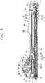
- FIG. 1 to FIG. 19 A first embodiment in which the present invention has been applied in a portable terminal will hereinafter be described with reference to FIG. 1 to FIG. 19 .
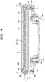
- This portable terminal is an information terminal such as a handy terminal for processing information, and has a device case 1, as shown in FIG. 1 to FIG. 3 .
- This device case 1, which is the main body of the terminal, is thinly formed in a substantially rectangular box shape, and includes an upper case 2 on the front surface side and a lower case 3 on the back surface side.
- the input display section 4 is provided corresponding to a wide area covering about three-fourths of the upper surface of the upper case 2 from one end portion 1a of the device case 1 toward the other end portion 1b side in a longitudinal direction of the device case 1.
- the key input section 5 is provided corresponding to an area excluding the input display section 4, that is, a narrow area covering about one-fourth of the upper surface of the upper case 2 from the other end portion 1b toward the input display section 4 in the longitudinal direction.
- the input display section 4 includes a display panel 4a and a transparent touch panel 4b laminated thereon, as shown in FIG. 1 , FIG. 3 and FIG. 4 .
- the display panel 4a is a flat display element such as a liquid crystal display element or an EL (Electro-Luminescence) display element, and is structured to electro-optically display information.
- the touch panel 4b is structured such that the user can input information by a touch operation while viewing information displayed on the display panel 4a.
- the key input section 5 includes a plurality of key buttons 5a arranged on the upper surface of the upper case 2 and located on the other end portion 1b side of the device case 1, and a switch board 5b arranged inside the upper case 2, as shown in FIG. 1 or FIG. 3 .
- the plurality of key buttons 5a includes an upper surface trigger key 5c in addition to key buttons such as numeric keys and function keys.
- the switch board 5b is arranged inside the upper case 2 and located under (above in the FIG.3 ) and corresponding to the plurality of key buttons 5a.
- a circuit board 6 is arranged corresponding to the input display section 4, as shown in FIG. 3 and FIG. 4 .
- This circuit board 6 electrically controls the entire portable terminal. More specifically, this circuit board 6 includes various types of electronic components 6a required for the portable terminal, and has electrically connected thereto the input display section 4, the switch board 5b, and later-described sections such as an optical reading section 9, an expansion connector 17, and a connection electrode section 11.
- a housing projection section 7 and a battery cover 8 are provided, as shown in FIG. 2 .
- the housing projection section 7 is provided corresponding to a narrow area covering about one-fourth of the undersurface of the lower case 3 and located on the one end portion 1a side of the device case 1 in the longitudinal direction. That is, the housing projection section 7 is provided on the side opposite to the input display section 4.
- the battery cover 8 is provided corresponding to an area excluding the housing projection section 7, that is, a wide area covering about three-fourths of the undersurface of the lower case 3 from the other end portion 1b of the device case 1 toward the housing projection section 7 in the longitudinal direction.
- the housing projection section 7 includes a first inclined surface 7a inclining toward the one end portion 1a side of the device case 1 and a second inclined surface 7b inclining toward the other end portion 1b side of the device case 1, and the longitudinal cross-sectional shape of the housing projection section 7 is a triangular shape, so that the housing projection section 7 has a substantially mountain shape as a whole, as shown in FIG. 2 and FIG. 3 .
- On the first inclined surface 7a an optical window section 7c is provided on the first inclined surface 7a. Also, in the housing projection section 7, the optical reading section 9 is housed.
- the optical reading section 9 includes a unit case 9a and a scanner section 9b which is imaging means attached to the unit case 9a, as shown in FIG. 3 .
- the unit case 9a is provided on the upper case 2 while corresponding to the housing projection section 7 of the lower case 3, and is arranged projecting toward the inside of the housing projection section 7 of the lower case 3.
- the scanner section 9b includes a laser reading section and a camera section, and is attached to the unit case 9a while corresponding to the optical window section 7c on the first inclined surface 7a of the housing projection section 7, as shown in FIG. 3 .
- the laser reading section irradiates a product code such as the bar code of a product with a laser beam, and reads out this product code by receiving reflected light.
- the camera section captures an image of a photographic subject such as a product, an item, and a two dimensional code.
- the battery cover 8 openably covers a battery housing section 3a in the lower case 3, as shown in FIG. 2 and FIG. 3 .
- This battery cover 8 has a substantially rectangular shape, and is provided with a grip section 8a located from the other end portion 1b side of the device case 1 to a middle portion of the battery cover 8.
- the grip section 8a has a curved shape which gradually projects rearward (upward in FIG. 3 ) with respect to the lower case 3, and a raised section 8b which is arranged between an index finger and a middle finger is formed on this curved portion.
- the battery cover 8 is structured such that, when this battery cover 8 is arranged on the lower case 3 and covers the battery housing section 3a of the lower case 3, its one end portion 8c on the housing projection section 7 side of the lower case 3 is arranged on an edge portion of the battery housing section 3a and its other end portion 8d on the other end portion 1b side of the device case 1 engages with another edge portion of the battery housing section 3a, as shown in FIG. 2 and FIG. 3 .
- the battery cover 8 is structured such that its one end portion 8c is locked by locking levers 10 with this battery cover 8 being arranged on the lower case 3 and covering the battery housing section 3a.
- the locking levers 10 are provided near the sides of the one end portion 8c of the battery cover 8 arranged close to a base portion of the housing projection section 7 of the lower case 3 on the second inclined surface 7b side, as shown in FIG. 2 and FIG. 5 .
- Each of these locking levers 10 includes a locking section 10a which is rotatably provided on the lower case 3 and detachably locks the one end portion 8c of the battery cover 8 on the housing projection section 7 side, and a lever section 10b which is provided extending toward the housing projection section 7 side from the locking section 10a and used to rotate the locking section 10a.
- these locking levers 10 are arranged in substantially fan-shaped lever housing recess sections 3b which are provided in the lower case 3 and extend from portions corresponding to the one end portion 8c of the battery cover 8 on the housing projection section 7 side to lower portions of the second inclined surface 7b of the housing projection section 7, as shown in FIG. 2 and FIG. 5 . That is, these locking levers 10 are structured such that the locking sections 10a are rotatably provided on pivot portions of the substantially fan-shaped lever housing recess sections 3b and the lever sections 10b are rotatable in the substantially fan-shaped lever housing recess sections 3b.
- the locking levers 10 are structured such that, when the lever sections 10b are operated in the lever housing recess sections 3b and each locking section 10a is rotated in one direction with the battery cover 8 being arranged on the lower case 3 and covering the battery housing section 3a of the lower case 3, the locking sections 10a press the one end portion 8c of the battery cover 8 against the edge portion of the battery housing section 3a and thereby lock the one end portion 8c, as shown in FIG. 2 and FIG. 5 .
- these locking levers 10 are structured such that, when the lever sections 10b are operated in the reverse directions with the locking sections 10a locking the one end portion 8c of the battery cover 8, and the locking sections 10a are rotated thereby in the reverse directions, the lock on the one end portion 8c of the battery cover 8 by the locking sections 10a is released, as shown in FIG. 2 and FIG. 5 .
- connection electrode section 11 On an end surface of the lower case 3 on the other end portion 1b side of the device case 1, the connection electrode section 11 is provided, as shown in FIG. 1 to FIG. 3 .
- This connection electrode section 11 has a plurality of electrodes 11a arranged therein, and is electrically connected to an external device such as a cradle (not shown in the drawings) so as to transmit information or charge a battery pack B in the battery housing section 3a.
- connection electrode section 11 The plurality of electrodes 11a in the connection electrode section 11 is covered and protected by an electrode cover 11b made of an elastic material such as rubber, as shown in FIG. 1 to FIG. 3 .
- the battery pack B includes a rechargeable battery B1 and a battery cover section B2. On a side surface of the device case 1, a side surface trigger key 1c is provided.
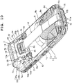
- a hand belt 12 can be attached in the longitudinal direction of the device case 1, as shown in FIG. 10 .
- This hand belt 12 is structured such that its one end portion 12a can be attached to a first belt attachment fitting 14 of an expansion cover 13 attached to the second inclined surface 7b of the housing projection section 7 of the lower case 3.
- this hand belt 12 is structured such that its other end portion 12b can be attached to a first belt attachment hole 3c provided in the other end of the lower case 3 and located at the other end portion 1b of the device case 1.
- connection electrode section 11 can be connected to an external device such as a cradle with the hand belt 12 being attached.
- an expansion connector section 50 which includes an expansion housing recess section 15, an expansion board 16, the expansion connector 17, and the expansion cover 13, as shown in FIG. 6 to FIG. 8 .
- This expansion connector section 50 is provided in a middle area in a transverse direction of the device case 1 that is the main body of the terminal.
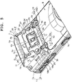
- the expansion housing recess section 15 is obliquely provided in substantially parallel with the second inclined surface 7b, and the expansion cover 13 is attached thereto, as shown in FIG. 6 to FIG. 8 .
- the expansion board 16 is obliquely provided in substantially parallel with the second inclined surface 7b.
- the expansion connector 17 is obliquely provided in substantially parallel with the second inclined surface 7b. That is, this expansion connector 17 is inclined in the longitudinal direction of the device case 1.
- the expansion board 16 is, for example, a card reading substrate (such as a non-contact IC (Integrated Circuit) reader writer board and a RFID (Radio Frequency Identifier) reader writer board) which reads information of a card such as a credit card in a non-contact manner, as shown in FIG. 3 and FIG. 6 to FIG. 8 .
- This expansion board 16 includes the board connector 16a which is connected to the expansion connector 17, and the expansion connector 17 having the board connector 16a connected thereto is electrically connected to the circuit board 6 in the upper case 2 by the connecting wire 17a.
- a magnetic electrode 16b which retrieves information of a card by a magnetic field (induced electromotive force) is provided, as shown in FIG. 3 .
- This magnetic electrode 16b is electrically connected to the circuit board 6 in the upper case 2 and is also electrically connected to the expansion board 16 via the circuit board 6.
- the expansion board 16 is structured to magnetically retrieve information signals of a card such as a credit card by the magnetic electrode 16b when this card is brought close to the outer surface of the housing projection section 7 of the lower case 3, and to read the retrieved magnetic information signals as information of the card.
- This expansion board 16 is obliquely arranged in the expansion housing recess section 15 in the second inclined surface 7b of the housing projection section 7 of the lower case 3 in substantially parallel with the second inclined surface 7b, and is thereby inclined in the longitudinal direction of the device case 1, as shown in FIG. 3 and FIG. 6 to FIG. 8 .
- this expansion board 16 is structured such that, even though its length in the longitudinal direction of the device case 1 is long, the longitudinal length of a space to be occupied thereby in the device case 1 is shorter because of its inclination with respect to the device case 1.
- the longitudinal length of a space to be occupied by the expansion board 16 in the device case 1 is shorter because of the inclination of the expansion board 16, as shown in FIG. 3 and FIG. 6 to FIG. 8 .
- the longitudinal length of a space to be occupied by the expansion board 16 in the device case 1 can be kept short.
- the expansion cover 13 covers the expansion housing recess section 15 in the second inclined surface 7b of the housing projection section 7 of the lower case 3 so as to protect the expansion board 16 in the expansion housing recess section 15, as shown in FIG. 3 and FIG. 6 to FIG. 9 .
- This expansion cover 13 includes a cover main body 18 and a waterproof panel 19, and has a structure where the waterproof panel 19 has been attached to the inner surface of the cover main body 18 by a two-sided adhesive tape 20. As a result, this expansion cover 13 is structured such that, by the waterproof panel 19, waterproofing is achieved and the strength of the cover main body 18 is increased.
- the above-described expansion cover 13 is arranged in the expansion housing recess section 15 in the second inclined surface 7b of the housing projection section 7 of the lower case 3 in substantially parallel with the second inclined surface 7b, and is thereby inclined in the longitudinal direction of the device case 1 as in the case of the expansion board 16, as shown in FIG. 3 and FIG. 6 to FIG. 9 .
- the expansion cover 13 is structured such that, even though its length in the longitudinal direction of the device case 1 is long, the longitudinal length of a space to be occupied thereby in the device case 1 is short because of its inclination with respect to the device case 1.
- the longitudinal length of a space to be occupied by the expansion cover 13 in the device case 1 is shorter because of the inclination of the expansion cover 13, as shown in FIG. 3 and FIG. 6 to FIG. 8 .
- the longitudinal length of a space to be occupied by the expansion cover 13 in the device case 1 can be kept short.
- the cover main body 18 is formed in a plate shape whose outer peripheral size is substantially equal to the inner peripheral size of the expansion housing recess section 15, as shown in FIG. 6 to FIG. 9 .
- attachment projection sections 18a are provided projecting in sideward directions.
- screw insertion holes 18b into which mounting screws 21 are inserted are provided in a direction substantially perpendicular to the longitudinal direction of the device case 1, and each of these screw insertion holes 18b includes a large-diameter hole portion into which a head section 21a of the corresponding mounting screw 21 is inserted and a small-diameter hole portion into which a screw section 21b of the mounting screw 21 is inserted.
- cutout sections 22 are provided in which the attachment projection sections 18a of the cover main body 18 are arranged, as shown in FIG. 8 .
- the expansion cover 13 is obliquely positioned on the device case 1 while being in substantially parallel with the second inclined surface 7b of the housing projection section 7.
- each cutout section 22 has a vertical surface 22a provided to be substantially perpendicular to the horizontal direction of the device case 1, and a horizontal surface 22b provided to be substantially parallel with the horizontal direction of the device case 1, as shown in FIG. 8 .
- screw holes 22c into which the screw sections 21b of the mounting screws 21 are screwed are provided to be substantially perpendicular to the horizontal surfaces 22b.
- the expansion cover 13 is structured such that, when the cover main body 18 is arranged in the expansion housing recess section 15 and the attachment projection sections 18a are arranged in the cutout sections 22, the screw insertion holes 18b of the attachment projection sections 18a are positioned coaxially with the screw holes 22c of the cutout sections 22 provided in the second inclined surface 7b of the housing projection section 7, as shown in FIG. 6 to FIG. 9 .
- the above-described pair of cutout sections 22 in the side portions of the second inclined surface 7b of the housing projection section 7 is structured such that side portions of the expansion board 16 can be easily held with fingertips of a hand when the expansion board 16 is arranged in or detached from the expansion housing recess section 15 after the expansion cover 13 is detached from the expansion housing recess section 15 of the housing projection section 7, as shown in FIG. 5 and FIG. 8 .
- the pair of cutout sections 22 is structured such that, when the board connector 16a of the expansion board 16 is to be inserted into or extracted from the expansion connector 17 in the expansion housing recess section 15 with side portions of the expansion board 16 being held with fingers of a hand, the fingertips holding the side portions of the expansion board 16 are placed on the cutout sections 22, as shown in FIG. 6 to FIG. 8 .
- the pair of cutout sections 22 is structured such that fingertips holding side portions of the expansion board 16 can be placed on side portions of the outer surface of the device case 1 in the transverse direction and in the expansion housing recess section 15, and therefore are not obstructed by side portions of the outer surface of the device case 1 in the transverse direction, as shown in FIG. 6 to FIG. 8 .
- the cover main body 18 has a cover packing hold-down section 18c provided on the outer peripheral portion of its inner surface in a frame shape, as shown in FIG. 6 to FIG. 9 .
- This cover packing hold-down section 18c is structured to hold down a cover packing 23 arranged along the inner periphery of the expansion housing recess section 15 provided in the second inclined surface 7b of the housing projection section 7.
- a cover mounting groove 15b in which the cover packing 23 is mounted is provided along the entire periphery.
- the cover packing 23 is arranged in this cover mounting groove 15b with it being upwardly exposed.
- the cover main body 18 is structured such that, when it is attached to the expansion housing recess section 15 by the mounting screws 21, the cover packing hold-down section 18c holds down the cover packing 23 mounted in the cover mounting groove 15b provided in the inner peripheral portion of the bottom part of the expansion housing recess section 15, whereby waterproofing for the expansion housing recess section 15 is achieved, as shown in FIG. 6 to FIG. 9 .
- the cover main body 18 is provided with a fitting attachment section 24 to which the first belt attachment fitting 14 is slidably attached, as shown in FIG. 5 and FIG. 9 .
- the first belt attachment fitting 14 is a fitting acquired by a metal plate being bent in a U-shape.
- a second belt attachment hole 14c is provided into which the one end portion 12a of the hand belt 12 is inserted to be attached.
- a fitting lock hole 14d is provided in a middle area on a lower surface plate 14b of this first belt attachment fitting 14.
- the fitting attachment section 24 includes a pair of first hold-down sections 25 which slidably holds down side portions of the first belt attachment fitting 14 and a second hold-down section 26 which resiliently holds a middle portion of the first belt attachment fitting 14, as shown in FIG. 5 , FIG. 8 and FIG. 9 .
- the pair of first hold-down sections 25 holds down the sides of the lower surface plate 14b of the first belt attachment fitting 14 against the outer surface of the cover main body 18.
- This pair of first hold-down sections 25 is provided in a sliding area on the cover main body 18 in which the first belt attachment fitting 14 is slid in the longitudinal direction of device case 1, that is, the inclination direction of the second inclined surface 7b of the housing projection section 7.
- the pair of first hold-down sections 25 includes a pair of projection sections 25a which is provided to upwardly project on side portions of the cover main body 18 in the transverse direction of the device case 1 and holds down the sides of the lower surface plate 14b, and a pair of hold-down grooves 25b which is provided under the pair of projection sections 25a and corresponds to the sides of the lower surface plate 14b of the first belt attachment fitting 14, as shown in FIG. 5 , FIG. 8 and FIG. 9 .
- the pair of hold-down grooves 25b is provided penetrating through the front and back surfaces of the cover main body 18 in the thickness direction, and upper end portions of the pair of projection sections 25a are formed to be positioned above these hold-down grooves 25b.
- the second hold-down section 26 is provided in a middle area on the cover main body 18 along the inclination of the second inclined surface 7b of the housing projection section 7 in a manner to form a tongue-like shape, as shown in FIG. 5 , FIG. 8 and FIG. 9 . More specifically, this second hold-down section 26 is structured to be flexurally deformed in the thickness direction of the cover main body 18, that is, the vertical direction by a slit hole 26a being provided under its body excluding one end portion serving as its base portion. On the other end portion of the second hold-down section 26, an engaging projection 26b is provided which disengageably engages with the fitting lock hole 14d in the lower surface plate 14b of the first belt attachment fitting 14.
- the first belt attachment fitting 14 is structured such that, when the lower surface plate 14b is arranged on the outer surface of the cover main body 18 and slid toward the base portion side of the second inclined surface 7b of the housing projection section 7, side portions of the lower surface plate 14b are inserted into areas under the pair of first hold-down sections 25, and a middle portion of the lower surface plate 14b downwardly presses the engaging projection 26b of the second hold-down section 26 and thereby flexurally deforms the second hold-down section 26, as shown in FIG. 5 , FIG. 8 and FIG. 9 .
- the first belt attachment fitting 14 is structured such that, when the lower surface plate 14b is slid on the outer surface of the cover main body 18 and the side portions of the lower surface plate 14b are inserted into the areas under the pair of first hold-down sections 25, these side portions are pressed against the cover main body 18 at positions corresponding to the hold-down grooves 25b of the pair of first hold-down sections 25, as shown in FIG. 5 , FIG. 8 and FIG. 9 .
- the first belt attachment fitting 14 is structured such that, when the side portions of the lower surface plate 14b are pressed against the cover main body 18, the second hold-down section 26 flexurally deformed by the middle portion of the lower surface plate 14b resiliently returns to its original position and the engaging projection 26b of the second hold-down section 26 engages with the fitting lock hole 14d of the lower surface plate 14b, whereby the first belt attachment fitting 14 is attached to the cover main body 18, as shown in FIG. 5 , FIG. 8 and FIG. 9 .
- a cover protection section 27 which reinforces the cover main body 18 is provided projecting in a frame shape, as shown in FIG. 5 to FIG. 9 . More specifically, the cover protection section 27 is provided to surround the fitting attachment section 24 along the outer periphery of the sliding area of the first belt attachment fitting 14. As a result, this cover protection section 27 is structured to reinforce the strength of a thin portion of the cover main body 18, that is, the strength of the fitting attachment section 24.
- the cover main body 18 is also large. As a result, the strength of the entire cover main body 18 is decreased. Accordingly, the thickness of the cover main body 18 is required to be increased.
- this cover main body 18 has the structure where the surrounding area of the fitting attachment section 24 has been reinforced by the cover protection section 27. Therefore, the strength of the cover main body 18 is ensured by the cover protection section 27 even though it is thin.
- the cover protection section 27 is formed in a manner to be located on its outer surface and project in a frame shape, as shown in FIG. 5 to FIG. 9 . Accordingly, even though the cover protection section 27 is provided, this cover protection section 27 does not project into the expansion housing recess section 15. As a result, the inner space of the expansion housing recess section 15 is not constrained by the cover protection section 27, whereby the internal volume thereof is ensured and high density storage can be achieved.
- the waterproof panel 19 is to achieve waterproofing for the cover main body 18, and is attached to the inner surface of the cover main body 18, or in other words, the undersurface of the cover main body 18 with the two-sided adhesive tape 20, as shown in FIG. 9 .
- the hold-down grooves 25b of the pair of first hold-down sections 25 in the cover main body 18 and the slit hole 26a of the second hold-down section 26 penetrate through the front and back surfaces of the cover main body 18, waterproofing for the expansion cover 13 is achieved and the strength of the cover main body 18 is increased by the hold-down grooves 25b of the pair of first hold-down sections 25 and the slit hole 26a of the second hold-down section 26 being closed by the waterproof panel 19.
- the waterproof panel 19 is provided with a clearance recess section 19a which allows the flexural deformation of the second hold-down section 26 of the fitting attachment section 24, as shown in FIG. 6 , FIG. 7 and FIG. 9 .
- This clearance recess section 19a has a shape conformed to the flexural deformation of the second hold-down section 26, and is obliquely provided in the waterproof panel 19 such that its portion on the leading end side of the second hold-down section 26 is deeply positioned and its portion on the base side of the second hold-down section 26 is shallowly positioned. That is, the clearance recess section 19a is provided to be inclined and project below the waterproof panel 19.
- leg sections 28 for supporting the device case 1 are provided, as shown in FIG. 5 , FIG. 11 and FIG. 12 . These leg sections 28 are arranged on the sides of the top part of the second inclined surface 7b of the housing projection section 7 in the transverse direction of the device case 1.
- the device case 1 is supported at three points, that is, the leg sections 28 provided on the sides of the housing projection section 7, and a portion of the lower case 3 on the other end portion 1b side of the device case 1.
- Each edge potion on the sides of the second inclined surface 7b of the housing projection section 7 in the transverse direction of the device case 1 is formed by an arc-shaped curved surface 7f, as shown in FIG. 5 .
- the above-described leg sections 28 are provided on these curved surfaces 7f of the edge portions on the sides of the second inclined surface 7b.
- Side surfaces 7d of the housing projection section 7 in the transverse direction of the device case 1 are curved at their portions connected to the second inclined surface 7b, and each leg section 28 project from three surfaces : the second inclined surface 7b of the housing projection section 7, one of the side surfaces 7d of the housing projection section 7 in the transverse direction of the device case 1, and a convex surface 7e on the top side of the second inclined surface 7b, as shown in FIG. 12 .
- Each of the above-described leg sections 28 includes a flexible member 29 which is made of elastomer or rubber and has elasticity, and a rigid member 30 which is made of a material harder than that of the flexible member 29 and fixed to the housing projection section 7 of the lower case 3, as shown in FIG. 13 .
- the flexible member 29 is an anti-slip member that prevents the portable terminal from slipping when it is arranged on the placement surface of a table or the like, as shown in FIG. 5 .
- This flexible member 29 is structured to protrude from the three surfaces, that is, the second inclined surface 7b of the housing projection section 7, one of the side surfaces 7d of the housing projection section 7 in the transverse direction of the device case 1, and the convex surface 7e on the top side of the second inclined surface 7b.
- the rigid member 30 includes a mounting section 30a on which the flexible member 29 is mounted, and a fixing shaft 30b which is provided on the undersurface of the mounting section 30a and inserted into and fixed in a leg attachment hole 31 provided in the housing projection section 7, as shown in FIG. 13 .
- the mounting section 30a herein is provided inclining with respect to the fixing shaft 30b.
- this mounting section 30a is structured to be arranged inclining in two directions, or more specifically, in the inclination direction of the second inclined surface 7b and the direction toward the corresponding side surface 7d of the housing projection section 7 by being arranged on the above-described three surfaces, that is, the second inclined surface 7b of the housing projection section 7, the corresponding side surface 7d of the housing projection section 7 in the transverse direction of the device case 1, and the convex surface 7e on the top side of the second inclined surface 7b, as shown in FIG. 5 , FIG. 11 and FIG. 12 .
- the fixing shaft 30b is arranged to be substantially perpendicular to the upper surface of the upper case 2, as shown in FIG. 5 and FIG. 11 to FIG. 13 .
- This fixing shaft 30b has a welding section 30c provided on a portion that is inserted into the corresponding leg attachment hole 31 of the housing projection section 7 and protrudes from this leg attachment hole 31 into the inside of the housing projection section 7.
- this fixing shaft 30b is fixed to the housing projection section 7, as shown in FIG. 11 and FIG. 12 with two-dot dashed lines.
- the attachment surface of the flexible member 29 and that of the mounting section 30a of the rigid member 30 are provided with projection and recess sections 29a and 30d, respectively, by which the flexible member 29 and the mounting section 30a of the rigid member 30 are fitted into each other, as shown in FIG. 11 and FIG. 12 .
- the flexible member 29 is integrally formed with the mounting section 30a of the rigid member 30 by insertion molding. In this embodiment, when the flexible member 29 is provided on the mounting section 30a of the rigid member 30 by insertion molding, the projection and recess sections 29a and 30d are fitted into each other and thereby firmly fixed to each other.
- a pair of third belt attachment holes 32 for attaching a predetermined component such as a hand belt or a strap (not shown) is provided, as shown in FIG. 14 to FIG. 16 .
- This pair of third belt attachment holes 32 is formed in both sides of the second inclined surface 7b of the housing projection section 7 in the transverse direction perpendicular to the longitudinal direction of the device case 1, and each third belt attachment hole 32 penetrates through two surfaces, or more specifically, the corresponding side surface 7d of the housing projection section 7 in the transverse direction of the device case 1 and the second inclined surface 7b.
- each third belt attachment hole 32 forms a first attachment hole 32a that is open to the second inclined surface 7b side and a second attachment hole 32b that is open to the corresponding side surface 7d side of the housing projection section 7 in the transverse direction of the device case 1, and is structured such that the inner portion of the first attachment hole 32a and the inner portion of the second attachment hole 32b are communicated with each other, as shown in FIG. 14 to FIG. 16 .
- This pair of third belt attachment holes 32 is provided as strap holes for attaching a strap (not shown) and also as holes for attaching the hand belt 12, as shown in FIG. 14 . More specifically, this pair of third belt attachment holes 32 is structured such that a second belt attachment fitting 33 for attaching the hand belt 12 is detachably attached thereto.
- the second belt attachment fitting 33 includes a fitting main body 34 to which the hand belt 12 is attached, and a pair of fitting mounting sections 35 provided on both ends of the fitting main body 34 in a bent state, as shown in FIG. 14 to FIG. 16 .
- the fitting main body 34 is formed in a square bar shape and structured to have a cover section 34a provided on its outer peripheral surface. The length of this fitting main body 34 is substantially the same as the length between the third belt attachment holes 32.
- the pair of fitting mounting sections 35 is structured to be inserted from above into and detachably attached to the first attachment holes 32a of the pair of third belt attachment holes 32 provided on both sides of the second inclined surface 7b of the housing projection section 7 in the transverse direction perpendicular to the longitudinal direction of the device case 1, as shown in FIG. 14 to FIG. 16 .
- each of the pair of fitting mounting sections 35 has a slit groove 35a provided in its middle portion in the transverse direction of the device case 1 in a manner to upwardly penetrate from the lower end in the longitudinal direction of the device case 1, as shown in FIG. 14 to FIG. 16 .
- the pair of fitting mounting sections 35 is structured to be flexurally deformed in the transverse directions of the device case 1 by the presence of the slit grooves 35a when being inserted into the first attachment holes 32a of the pair of third belt attachment holes 32 from the second inclined surface 7b side of the housing projection section 7.
- engaging projections 35b are provided which disengageably engage with inner portions of the second attachment holes 32b of the pair of third belt attachment holes 32 penetrating through the side surfaces 7d of the housing projection section 7 located in the transverse direction of the device case 1, as shown in FIG. 14 to FIG. 16 .
- the pair of fitting mounting sections 35 is structured such that they resiliently return in directions away from each other after being inserted into the first attachment holes 32a of the pair of third belt attachment holes 32 from the second inclined surface 7b side of the housing projection section 7 and flexurally deformed, whereby the engaging projections 35b engage with the inner portions of the second attachment holes 32b of the pair of third belt attachment holes 32, as shown in FIG. 14 to FIG. 16 .
- the pair of fitting mounting sections 35 is structured such that, in order to release the engagement of the engaging projections 35b with the inner portions of the second attachment holes 32b of the pair of third belt attachment holes 32, a tool is inserted into each second attachment hole 32b from the corresponding side surface 7d side of the housing projection section 7 in the transverse direction of the device case 1, and presses each engaging projection 35b so as to flexurally deform the corresponding fitting mounting section 35, whereby the engaging projections 35b are separated from the second attachment holes 32b, and the fitting mounting sections 35 are detached from the third belt attachment holes 32, as shown in FIG. 14 to FIG. 16 .
- each of the pair of third belt attachment holes 32 is structured such that the string of a strap not shown is inserted from one of its first attachment hole 32a and second attachment hole 32b into the other hole. As a result, a strap can be attached to either one of the pair of third belt attachment holes 32.
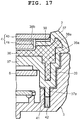
- the upper case 2 of the device case 1 includes a case main body section 36 which is a reinforcement member made of a highly rigid material, and an outer peripheral cover section 37 which is made of synthetic resin and is provided covering the outer peripheral edges and undersurface of the case main body section 36, as shown in FIG. 17 and FIG. 18 .
- the case main body section 36 has a plate-like shape and the above-described highly rigid material therefor is, for example, a metal such as magnesium alloy, stainless steel, and aluminum alloy, reinforced plastic, or a material acquired by carbon fibers or glass fibers being woven and solidified.
- This case main body section 36 includes a first reinforcement section 38 which is a second extending section thicker than other portions and extends from the outer peripheral edge portion of the case main body section 36, a second reinforcement section 39 which is a first extending section provided in a frame shape along the outer periphery of the case main body section 36 and projects from the undersurface of the first reinforcement section 38, and a uniting section 36a which unites the first reinforcement section 38 with the second reinforcement section 39, as shown in FIG. 17 and FIG. 18 .
- This uniting section 36a is formed to be thicker than the first reinforcement section 38.
- the outer peripheral cover section 37 is provided covering the outer peripheral portion and undersurface of the case main body section 36, or in other words, the first reinforcement section 38, the second reinforcement section 39, the uniting section 36a, and the undersurface of the case main body section 36.
- the first reinforcement section 38 and the second reinforcement section 39 are formed such that their cross sections have a T-shape, as shown in FIG. 17 and FIG. 18 .
- the first reinforcement section 38 and the second reinforcement section 39 are structured such that their rigidities are increased, their strengths are ensured, and their high pressing forces are maintained against the elasticity of a waterproof packing 42 described later, whereby high waterproofness can be ensured.
- a protection projection section 38a having a chevron shape is provided projecting upward, as shown in FIG. 17 and FIG. 18 .
- This protection projection section 38a protects the outer peripheral portion of the input display section 4 arranged on the case main body section 36.
- the first reinforcement section 38 is structured such that the undersurface of this protection projection section 38a is arranged corresponding to the outer peripheral edge portion of the lower case 3.
- This first reinforcement section 38 has a stepped section 38b which is provided at the boundary between this first reinforcement section 38 and the case main body section 36 and exposed without being covered by the outer peripheral cover section 37.
- the outer peripheral cover section 37 is structured such that, when the upper case 2 is superposed on and attached to the lower case 3, the outer peripheral surface of the outer peripheral cover section 37 comes in close contact with and arranged on the upper surface of the outer peripheral edge portion of the lower case 3 and the inner peripheral surface thereof, as shown in FIG. 17 and FIG. 18 .
- a packing hold-down rib 37a which is a packing hold-down section corresponding to the second reinforcement section 39 is provided in a frame shape and projects toward the lower case 3 side.
- a case packing groove 41 is provided along the inner peripheral surface thereof, as shown in FIG. 17 and FIG. 18 .
- the waterproof packing 42 is arranged.
- the device case 1 is structured such that, when the upper case 2 is superposed on and attached to the lower case 3, the packing hold-down rib 37a of the outer peripheral cover section 37 is pressed into the case packing groove 41 of the lower case 3 by the second reinforcement section 39 and thereby holds down the waterproof packing 42.
- this device case 1 is structured such that, when the upper case 2 is superposed on and pressed against the lower case 3, the second reinforcement section 39 provided on the case main body section 36 of the upper case 2 presses down the packing hold-down rib 37a of the outer peripheral cover section 37 into the case packing groove 41 of the lower case 3, and the pressed packing hold-down rib 37a holds down the waterproof packing 42 in the case packing groove 41 of the lower case 3, as shown in FIG. 17 and FIG. 18 .
- this device case 1 is structured such that, when the waterproof packing 42 in the case packing groove 41 is held down by the packing hold-down rib 37a, the outer peripheral surface of the outer peripheral cover section 37 comes in close contact with and arranged on the upper surface of the outer peripheral edge portion of the lower case 3 and the inner peripheral surface thereof, as shown in FIG. 17 and FIG. 18 .
- This method for manufacturing the upper case 2 includes a first step of forming the case main body section 36 that is a reinforcement member by use of a highly rigid material, a second step of fixing the case main body section 36 in a molding die 45, and a third step of injecting resin into the molding die 45 so as to form the outer peripheral cover section 37 on the case main body section 36.
- the case main body section 36 having a substantially plate-like shape is formed with a highly rigid material.
- This material is, for example, a metal such as magnesium alloy, stainless steel, and aluminum alloy, reinforced plastic, or a material acquired by carbon fibers or glass fibers being woven and solidified.
- the thick first reinforcement section 38 which extends from the outer peripheral portion of the case main body section 36 and the second reinforcement section 39 which is positioned on the first reinforcement section 38 are formed.
- the protection projection section 38a which has a chevron shape and protects the outer peripheral portion of the input display section 4 is provided projecting upward (downward in FIG.19 ) .
- the stepped section 38b is formed to be higher (lower in FIG. 19 ) than the upper (lower in FIG. 19 ) surface of the case main body section 36.
- the case main body section 36 is arranged in the molding die 45.
- This molding die 45 includes a lower die 46 and an upper die 47.
- the case main body section 36 is placed inside the lower die 46 and the upper die 47.
- an engagement projection section 46a which is a portion of the lower die 46 is brought into contact with the stepped section 38b of the first reinforcement section 38 located at the boundary with the case main body section 36, and the outer peripheral surface of the engagement projection section 46a is pressed against the inner peripheral surface of the stepped section 38b.
- the case main body section 36 is positionally restricted with respect to the lower die 46 and fixed in the molding die 45.
- a molding space (cavity) 48 for the outer peripheral cover section 37 has been formed in the molding die 45.
- This molding space 48 includes a first space 48a surrounding the outer peripheral portions of the first reinforcement section 38 and the second reinforcement section 39, a groove-shaped second space 48b located below (above in FIG.19 ) the second reinforcement section 39 on the same axis, and a third space corresponding to the lower side (upper side in FIG.19 ) of the case main body section 36.
- the outer peripheral cover section 37 is integrally formed on the outer peripheral portions of the first reinforcement section 38 and second reinforcement section 39 of the case main body section 36 by use of the first space 48a of the molding space 48.
- the packing hold-down rib 37a of the outer peripheral cover section 37 is formed under and corresponding to the second reinforcement section 39 by use of the second space 48b of the molding space 48.
- the outer peripheral cover section 37 is formed under the case main body section 36 by use of the third space 48c of the molding space 48.
- the lower die 46 and upper die 47 of the molding die 45 are detached from each other, whereby the upper case 2 that is a molded article is taken out from the molding die 45.
- the stepped section 38b of the first reinforcement section 38 located at the boundary with the case main body section 36 has been exposed without being covered by the outer peripheral cover section 37.
- the upper case 2 having the outer peripheral cover section 37 provided on the outer peripheral portion of the case main body section 36 is acquired.
- the waterproof packing 42 is arranged in the case packing groove 41 of the lower case 3 provided along the inner peripheral surface of the lower case 3, as shown in FIG. 17 and FIG. 18 .
- the upper case 2 is superposed on the lower case 3 such that the packing hold-down rib 37a of the outer peripheral cover section 37 of the upper case 2 corresponds to the case packing groove 41 of the lower case 3.
- the lower case 3 is pressed against the upper case 2.
- the packing hold-down rib 37a of the outer peripheral cover section 37 of the upper case 2 is pressed into the case packing groove 41 of the lower case 3 by the second reinforcement section 39 of the upper case 2.
- This pressed packing hold-down rib 37a presses the waterproof packing 42 in the case packing groove 41.
- waterproofing for the upper case 2 and the lower case 3 is achieved.
- the outer peripheral surface of the outer peripheral cover section 37 comes in close contact with and is arranged on the upper surface and inner peripheral surface of the outer peripheral edge portion of the lower case 3. As a result, the assembly of the device case 1 is completed.
- the input display section 4 and the key input section 5 are mounted on the front surface of the upper case 2.
- the input display section 4 having the transparent touch panel 4b laminated on the display panel 4a in advance is mounted on the upper case 2.
- the key input section 5 having the plurality of key buttons 5a arranged on the switch board 5b is mounted on the upper case 2.
- the circuit board 6 is mounted corresponding to the input display section 4, and also the unit case 9a of the optical reading section 9 is mounted.
- the scanner section 9b including the laser reading section and the camera section and the expansion connector 17 are attached to the unit case 9a in advance.
- the connection electrode section 11 is mounted on the end portion of the upper case 2 on the other end portion 1b side of the device case 1 in the longitudinal direction.
- the side surface trigger key 1c is mounted on the side surface of the upper case 2.
- the input display section 4, the switch board 5b of and the key input section 5, the scanner section 9b, the expansion connector 17, the connection electrode section 11, and the side surface trigger key 1c are electrically connected to the circuit board 6.
- the various types of components are mounted on the upper case 2.
- the optical window section 7c is attached to the first inclined surface 7a of the housing projection section 7.
- the upper case 2 is superposed on the lower case 3 as described above so as to assemble the device case 1.
- the scanner section 9b of the unit case 9a of the optical reading section 9 provided in the upper case 2 corresponds to the optical window section 7c provided on the first inclined surface 7a of the housing projection section 7 of the lower case 3.
- the expansion connector 17 provided on the unit case 9a is inserted into the opening section 15a of the bottom portion of the expansion housing recess section 15 in the second inclined surface 7b of the housing projection section 7, and exposed in the expansion housing recess section 15.
- the bottom portion of the expansion housing recess section 15 is obliquely arranged in substantially parallel with the second inclined surface 7b of the housing projection section 7.
- the expansion connector 17 exposed in the expansion housing recess section 15 is obliquely arranged in substantially parallel with the second inclined surface 7b of the housing projection section 7 and inclined with respect to the longitudinal direction of the device case 1.
- the expansion board 16 is arranged in the expansion housing recess section 15.
- the board connector 16a provided on the undersurface of the expansion board 16 is inserted into the expansion connector 17 exposed in the expansion housing recess section 15 so that the expansion board 16 is electrically connected and attached to the expansion connector 17.
- the expansion board 16 is obliquely arranged in the expansion housing recess section 15 in substantially parallel with the second inclined surface 7b of the housing projection section 7.
- the longitudinal length of a space occupied by the expansion board 16 in the device case 1 is short. That is, in the case where the expansion board 16 is obliquely arranged with respect to the device case 1 in the longitudinal direction, the longitudinal length of a space to be occupied by the expansion board 16 in the device case 1 is shorter because of the inclination of the expansion board 16, as compared to a case where the expansion board 16 is arranged in parallel with the device case 1 in the longitudinal direction. Therefore, even though the length of the expansion board 16 in the longitudinal direction of the device case 1 is long, the longitudinal length of a space to be occupied by the expansion board 16 in the device case 1 can be kept short.
- the expansion connector 17 is arranged in the expansion housing recess section 15 in manner to be long in the transverse direction of the device case 1.
- the expansion board 16 can be easily tilted in the transverse direction of the device case 1, whereby the board connector 16a of the expansion board 16 can be easily and favorably inserted into the expansion connector 17.
- the board connector 16a of the expansion board 16 when the board connector 16a of the expansion board 16 is to be inserted into the expansion connector 17 with the side portions of the expansion board 16 in the transverse direction of the device case 1 being held by the fingertips, the fingertips holding the side portions of the expansion board 16 can be placed on the cutout sections 22 provided in the side portions of the second inclined surface 7b of the housing projection section 7 in the transverse direction of the device case 1.
- the board connector 16a of the expansion board 16 can be easily and favorably inserted into the expansion connector 17.
- the expansion cover 13 is attached to the expansion housing recess section 15 so as to protect the expansion board 16.
- the expansion cover 13 is assembled in advance.
- the waterproof panel 19 is attached to the inner surface of the cover main body 18 of the expansion cover 13 with the two-sided adhesive tape 20, whereby the expansion cover 13 is assembled in which waterproofing has been achieved by the waterproof panel 19 and the strength of the cover main body 18 has been enhanced.
- the cover packing 23 is mounted in the cover mounting groove 15b provided in the inner peripheral surface of the expansion housing recess section 15, and then the expansion cover 13 is attached to the expansion housing recess section 15 in this state.
- the cover packing hold-down section 18c of the expansion cover 13 holds down the cover packing 23 mounted in the cover mounting groove 15b of the expansion housing recess section 15, whereby waterproofing for the expansion cover 13 and the expansion housing recess section 15 is achieved.
- the attachment projection sections 18a provided projecting on the sides of the cover main body 18 in the transverse directions of the device case 1 are arranged in the cutout sections 22 provided in the side portions of the second inclined surface 7b of the housing projection section 7 in the transverse direction of the device case 1.
- the attachment projection sections 18a of the expansion cover 13 are arranged on the horizontal surfaces 22b of the cutout sections 22 and also come in contact with the vertical surfaces 22a of the cutout sections 22. As a result, the expansion cover 13 is accurately and favorably attached to the expansion housing recess section 15.
- each screw insertion hole 18b provided in the attachment projection sections 18a is positioned on the same axis as the screw hole 22c provided in the horizontal surface 22b of the corresponding cutout section 22. Accordingly, the mounting screws 21 are inserted into the screw insertion holes 18b of the attachment projection sections 18a while being substantially perpendicular to the longitudinal direction of the device case 1, and the screw sections 21b of the mounting screws 21 are tightly screwed into the screw holes 22c of the cutout sections 22.
- the cover packing hold-down section 18c of the expansion cover 13 holds down the cover packing 23 mounted in the cover mounting groove 15b of the expansion housing recess section 15, and the expansion cover 13 is attached to the expansion housing recess section 15 with the cover main body 18 covering the expansion housing recess section 15.
- the expansion cover 13 is arranged in the expansion housing recess section 15 in substantially parallel with the second inclined surface 7b of the housing projection section 7. Accordingly, as in the case of the expansion board 16, the longitudinal length of a space to be occupied by the expansion cover 13 in the device case 1 can be kept short because of its inclination with respect to the device case 1.
- the longitudinal length of a space to be occupied by the expansion cover 13 in the device case 1 is shorter because of the inclination of the expansion cover 13, as compared to a case where the expansion cover 13 is arranged in parallel with the device case 1 in the longitudinal direction. Therefore, even though the length of the expansion cover 13 in the longitudinal direction of the device case 1 is long, the longitudinal length of a space to be occupied by the expansion cover 13 in the device case 1 can be kept short.
- the battery pack B is housed in the battery housing section 3a in the lower case 3, and the battery cover 8 is attached to this battery housing section 3a.
- the other end portion 8d of the battery cover 8 is placed to be caught on an edge portion of the battery housing section 3a on the other end portion 1b side of the device case 1, and the one end portion 8c of the battery cover 8 is arranged on an edge portion of the battery housing section 3a on the housing projection section 7 side.
- the one end portion 8c of the battery cover 8 is locked by the locking levers 10.
- the lever sections 10b of the locking levers 10 are operated in the lever housing recess sections 3b of the lower case 3 so as to rotate each locking section 10a in one direction, with the battery cover 8 being arranged on the lower case 3 and covering the battery housing section 3a of the lower case 3.
- the locking sections 10a hold down the one end portion 8c of the battery cover 8 on the edge portion of the battery housing section 3a, whereby the one end portion 8c is locked and the assembly of the portable terminal is completed.
- the hand belt 12 is attached to the portable terminal in advance.
- the first belt attachment fitting 14 is attached to the expansion cover 13. That is, the lower surface plate 14b of the first belt attachment fitting 14 is arranged on the outer surface of the cover main body 18 and slid toward the base side of the second inclined surface 7b of the housing projection section 7.
- the side portions of the lower surface plate 14b of the first belt attachment fitting 14 are inserted toward the areas under the pair of first hold-down sections 25 on the sides of the fitting attachment section 24 provided in the expansion cover 13, and the middle portion of the lower surface plate 14b of the first belt attachment fitting 14 downwardly presses the engaging projection 26b of the second hold-down section 26 of the fitting attachment section 24 and thereby flexurally deforms the second hold-down section 26 toward the back side.
- the cover protection section 27 which reinforces the cover main body 18 is provided on the outer surface of the cover main body 18 and surrounds the fitting attachment section 24 along the outer periphery of the sliding area of the first belt attachment fitting 14, whereby a thin portion of the cover main body 18 is reinforced, or in other words, the strength of the fitting attachment section 24 is increased.
- the cover main body 18 is also formed larger, by which the strength of the entire cover main body 18 is decreased. Therefore, the thickness of the cover main body 18 is required to be increased.
- this cover main body 18 has the structure where the surrounding area of the fitting attachment section 24 has been reinforced by the cover protection section 27, and therefore the strength of the cover main body 18 is ensured by the cover protection section 27 even though it is thin.
- the cover protection section 27 is formed in a manner to be located on its outer surface and project in a frame shape. Accordingly, even though the cover protection section 27 is provided on the cover main body 18, this cover protection section 27 does not project into the expansion housing recess section 15. As a result, the inner space of the expansion housing recess section 15 is not constrained by the cover protection section 27, whereby the internal volume thereof is ensured and high density storage can be achieved.
- the one end portion 12a of the hand belt 12 is inserted into and attached to the second belt attachment hole 14c provided in the upper surface plate 14a of the first belt attachment fitting 14.
- the other end portion 12b of the hand belt 12 is attached to the first belt attachment hole 3c provided in the other end of the lower case 3 on the other end portion 1b side of the device case 1 in the longitudinal direction.
- the hand belt 12 is attached to the portable terminal.
- the user when using the portable terminal while holding it, the user first inserts his or her hand between the device case 1 and the hand belt 12 and holds the device case 1.
- the fingers other than the thumb are inserted between the device case 1 and the hand belt 12 and the thumb is placed on the input display section 4 or key input section 5 of the device case 1 so as to hold the device case 1 while wrapping the fingers around the battery cover 8 of the device case 1.
- the user performs an input operation on the input display section 4 or the key input section 5 with the thumb.
- information displayed on the display panel 4a of the input display section 4 can be viewed through the transparent touch panel 4b. Accordingly, the user can perform a touch operation while viewing the information displayed on the display panel 4a.
- the scanner section 9b of the optical reading section 9 is activated. Then, the laser reading section of the scanner section 9b irradiates the product code of a product with a laser beam through the optical window section 7c of the housing projection section 7, and receives reflected light so as to read the product code.
- the camera section of the scanner section 9b captures an image of a photographic subject such as the product or the two dimensional code.
- the product code read by the laser reading section is registered in the memory section of the circuit board 6 while being displayed on the input display section 4 and, similarly, the image of the photographic subject such as the product or the two dimensional code captured by the camera section is registered in the memory section of the circuit board 6 while being displayed on the input display section 4.
- the magnetic electrode 16b provided in the housing projection section 7 acquires information of the card with a magnetic field (induced electromotive force), and the acquired magnetic information signal is read as card information by the expansion board 16. This read information is also registered in the memory section of the circuit board 6.
- the three points that is, the two leg sections 28 provided on the sides of the housing projection section 7 of the lower case 3 in the transverse direction and a portion of the lower case 3 on the other end portion 1b side of the device case 1, or in other words, the other end portion 12b of the hand belt 12 attached to an end portion of the lower case 3 come in contact with the placement surface.
- the device case 1 is stably arranged on the placement surface since it is supported by the three points on the placement surface.
- the leg sections 28 provided on the sides of the housing projection section 7 are arranged on the placement surface, the flexible members 29 of the leg sections 28 are arranged on and come in contact with the placement surface, whereby slipping on the placement surface is prevented by the elastic force of the flexible members 29.
- the device case 1 is stably arranged on the placement surface.
- the flexible members 29 of the leg sections 28 are formed of materials having elasticity, such as elastomer or rubber.
- the expansion cover 13 cannot be attached to the expansion housing recess section 15. Therefore, the portable terminal is required to be used with the expansion cover 13 being detached, and accordingly an attachment position of the hand belt 12 with respect to the device case 1 is required to be changed.
- the one end portion 12a of the hand belt 12 is detached from the first belt attachment fitting 14.
- the second belt attachment fitting 33 is attached to the pair of third belt attachment holes 32 provided in the sides of the second inclined surface 7b of the housing projection section 7 of the lower case 3 in the transverse direction perpendicular to the longitudinal direction of the device case 1.
- the pair of fitting mounting sections 35 provided on the ends of the fitting main body 34 of the second belt attachment fitting 33 is inserted into and attached to the first attachment holes 32a of the pair of third belt attachment holes 32.
- the engaging projections 35b are pressed against the inner surfaces of the first attachment holes 32a and flexurally deformed by the presence of the slit grooves 35a.
- the one end portion 12a of the hand belt 12 is inserted between the fitting main body 34 of the second belt attachment fitting 33 and the second inclined surface 7b of the housing projection section 7 of the lower case 3, and folded back at the fitting main body 34.
- the one end portion 12a of the hand belt 12 is attached to the fitting main body 34.
- the first belt attachment fitting 14 may be detached from the expansion cover 13 or may remain attached.
- the user can use the portable terminal while holding it. More specifically, his or her hand is inserted between the device case 1 and the hand belt 12 so as to hold the device case 1.
- his or her hand is inserted between the device case 1 and the hand belt 12 so as to hold the device case 1.
- the fingers other than the thumb are inserted between the device case 1 and the hand belt 12 and the thumb is placed on the input display section 4 or the key input section 5 of the device case 1 so as to hold the device case 1 while wrapping the fingers around the battery cover 8 of the device case 1.
- the hand belt 12 may remain attached to the device case 1 or be detached from the device case 1.
- the second belt attachment fitting 33 may be detached from the pair of third belt attachment holes 32 so as to attach a strap (not shown in the drawings) to one of the pair of third belt attachment holes 32.
- the string of the strap is inserted from the first attachment hole 32a of one of the third belt attachment holes 32 to the corresponding second attachment hole 32b or vice versa.
- this portable terminal includes the housing projection section 7 which is provided projecting in the thickness direction at a position shifted to the one end portion 1a side of the device case 1 that is a terminal main body in the longitudinal direction and in which a predetermined device is housed, and the expansion connector section 50 which is used to connect the predetermined expansion board 16.
- the housing projection section 7 has the second inclined surface 7b downwardly inclined from the one end portion 1a side toward the other end portion 1b side in the longitudinal direction, and the expansion connector section 50 is provided in this second inclined surface 7b.
- the expansion connector section 50 is provided in the housing projection section 7 with it being inclined in the longitudinal direction of the device case 1. Accordingly, when being connected to the expansion connector section 50, the expansion board 16 which expands the function or the like can be obliquely arranged on the housing projection section 7. As a result of this structure, the device case 1 can be downsized, and the portable terminal can be favorably carried even after its function is expanded.
- the expansion connector section 50 includes the expansion connector 17 that is a terminal section for electrically connecting the expansion board 16, and the expansion housing recess section 15 for housing the expansion board 16 connected to the expansion connector 17.
- the expansion connector 17 is provided in the bottom surface portion of the expansion housing recess section 15. That is, by the presence of the expansion housing recess section 15, the expansion connector 17 can be provided in the housing projection section 7 without protruding from the second inclined surface 7b of the housing projection section 7.
- the expansion connector 17 that is a terminal section is provided such that the expansion board 16 can be mounted in parallel with the second inclined surface 7b. Accordingly, when the board connector 16a of the expansion board 16 having an expansion function is connected to the expansion connector 17, the expansion board 16 is obliquely arranged along the second inclined surface 7b of the housing projection section 7.
- the device case 1 can be downsized, and the portable terminal can be favorably carried even after its function is expanded.
- the expansion connector 17 that is a terminal section is provided such that its length in the longitudinal direction of the device case 1 is shorter than its length in the transverse direction of the device case 1. Accordingly, the user can easily tilt the expansion board 16 in the transverse directions of the device case 1 when inserting the board connector 16a into the expansion connector 17 while holding side portions of the expansion board 16 located in the transverse direction of the device case 1 with fingertips, and thereby can easily and favorably insert the board connector 16a of the expansion board 16 into the expansion connector 17.
- the expansion connector section 50 includes the expansion cover 13 that is a cover body for covering the expansion housing recess section 15, and the housing projection section 7 has the screw holes 22c into which the mounting screws 21 for attaching the expansion cover 13 are screwed. These screw holes 22c are formed extending in the thickness direction of the device case 1.
- the mounting screws 21 can be screwed into the screw holes 22c of the housing projection section 7 in the thickness direction of the device case 1, that is, the direction substantially perpendicular to the longitudinal direction of the device case 1, whereby the attachment projection sections 18a of the expansion cover 13 can be reliably and firmly attached to the cutout sections 22 of the expansion housing recess section 15.
- the expansion connector section 50 is provided at a position shifted toward the other end portion 1b side of the device case 1, in the second inclined surface 7b. Accordingly, the expansion connector section 50 does not obstruct the use of the portable terminal and the user can favorably use the portable terminal while holding the device case 1.
- the scanner section 9b of the optical reading section 9 that is imaging means is housed in the housing projection section 7.
- the device case 1 can be downsized.
- the scanner section 9b is provided on the unit case 9a of the optical reading section 9 provided on the upper case 2 corresponding to the housing projection section 7 of the lower case 3, and is arranged in the housing projection section 7 of the lower case 3 when the upper case 2 and the lower case 3 are attached to each other so as to assemble the device case 1. That is, the assembling work is efficiently performed.
- one expansion connector 17 is provided in the expansion housing recess section 15 in the second inclined surface 7b of the housing projection section 7.
- the present invention is not limited thereto.
- a plurality of expansion connectors may be provided. With this structure, more functions can be expanded by the plurality of expansion connectors.
- the expansion board 16 is a card reading board which reads information of a card such as a credit card in a non-contact manner.
- the present invention is not limited thereto.
- the expansion board 16 may be a sensor board equipped with a sensor such as a temperature sensor (thermostat camera), a pressure sensor, an infrared sensor, a distance sensor, and a biometrics sensor (a fingerprint sensor or a pulse sensor), or a communication board equipped with a communication function.
- the fixing shafts 30b of the rigid members 30 of the leg sections 28 are fixed in the leg attachment holes 31 of the housing projection section 7 by the welding sections 30c.
- the present invention is not limited thereto.
- the fixing shafts 30b may be fixed in the leg attachment holes 31 of the housing projection section 7 by screws or stopper components such as E-rings and split pins.
Landscapes
- Engineering & Computer Science (AREA)
- Theoretical Computer Science (AREA)
- Computer Hardware Design (AREA)
- Physics & Mathematics (AREA)
- General Engineering & Computer Science (AREA)
- General Physics & Mathematics (AREA)
- Human Computer Interaction (AREA)
- Signal Processing (AREA)
- Electromagnetism (AREA)
- Health & Medical Sciences (AREA)
- Toxicology (AREA)
- Computer Networks & Wireless Communication (AREA)
- General Health & Medical Sciences (AREA)
- Artificial Intelligence (AREA)
- Computer Vision & Pattern Recognition (AREA)
- Casings For Electric Apparatus (AREA)
- Telephone Set Structure (AREA)
Abstract
Description
- The present invention relates to an information terminal such as a portable information processing device and a portable communication device.
- For example, an information terminal is known which has a structure where an expansion connector has been provided in a side portion of its case and a connection section of an extended display device has been detachably attached to the expansion connector so as to electrically connect the case with the extended display device and display the information of a display target on the extended display device (for example, refer to Japanese Patent Application Laid-Open (Kokai) Publication No.
2003-233437 - In the case of the above-described information terminal, when the connection section of the extended display device is attached to the expansion connector provided in the side portion of the case so as to electrically connect the case with the extended display device, the extended display device notably sticks out from the side of the case. This structure causes a problem in that, when being carried with the extended display device attached to the case, the information terminal cannot be favorably carried due to the presence of the extended display device.
- In accordance with one aspect of the present invention, there is provided an information terminal comprising: a housing projection section which is provided at a position shifted to one end side of a terminal main body in a longitudinal direction while projecting in a thickness direction of the terminal main body, and in which a device is housed; and an expansion connector section which is used to connect an expansion board, wherein the housing projection section includes an inclined section downwardly inclined from the one end side toward an other end side in the longitudinal direction, and wherein the expansion connector section is provided in the inclined section.
- The above and further objects and novel features of the present invention will more fully appear from the following detailed description when the same is read in conjunction with the accompanying drawings. It is to be expressly understood, however, that the drawings are for the purpose of illustration only and are not intended as a definition of the limits of the invention.
- The present invention can be more clearly understood by the detailed description below being considered together with the following drawings.
-
FIG. 1 is a perspective view of a first embodiment in which the present invention has been applied in a portable terminal; -
FIG. 2 is a perspective view of the back surface side of the portable terminal shown inFIG. 1 ; -
FIG. 3 is an enlarged cross-sectional view of the portable terminal taken along the A-A arrow view shown inFIG. 2 ; -
FIG. 4 is an enlarged cross-sectional view of the portable terminal taken along the B-B arrow view shown inFIG. 1 ; -
FIG. 5 is an enlarged perspective view of a main portion showing a housing projection section of the portable terminal shown inFIG. 2 ; -
FIG. 6 is an enlarged cross-sectional view of the housing projection section of the portable terminal taken along the C-C arrow view shown inFIG. 5 ; -
FIG. 7 is an enlarged cross-sectional view of the main portion, in which an expansion cover and an expansion board have been detached from the housing projection section of the portable terminal shown inFIG. 6 ; -
FIG. 8 is an exploded perspective view of the main portion of the portable terminal shown inFIG. 7 ; -
FIG. 9 is an enlarged perspective view of a main portion, in which the expansion cover and a first belt attachment fitting shown inFIG. 8 have been detached; -
FIG. 10 is a perspective view of the portable terminal shown inFIG. 2 , in which a hand belt has been attached to the portable terminal; -
FIG. 11 is an enlarged cross-sectional view showing a leg section of the housing projection section of the portable terminal taken along the D-D arrow view shown inFIG. 5 ; -
FIG. 12 is an enlarged cross-sectional view showing leg sections of the housing projection section of the portable terminal taken along the E-E arrow view shown inFIG. 5 ; -
FIG. 13 is an enlarged perspective view showing a state where the leg section shown inFIG. 11 has been disassembled; -
FIG. 14 is a perspective view showing a state where a second belt attachment fitting has been attached to the housing projection section of the portable terminal shown inFIG. 2 ; -
FIG. 15 is a perspective view showing a state where the second belt attachment fitting shown inFIG. 14 has been detached from the portable terminal; -
FIG. 16 is an enlarged perspective view of the second belt attachment fitting shown inFIG. 15 ; -
FIG. 17 is an enlarged cross-sectional view showing a main portion of the device case of the portable terminal shown inFIG. 4 ; -
FIG. 18 is an enlarged cross-sectional view showing detachment in the device case shown inFIG. 17 ; and -
FIG. 19 is an enlarged cross-sectional view showing a main portion of a molding die for molding an upper case shown inFIG. 4 . - A first embodiment in which the present invention has been applied in a portable terminal will hereinafter be described with reference to
FIG. 1 to FIG. 19 . - This portable terminal is an information terminal such as a handy terminal for processing information, and has a
device case 1, as shown inFIG. 1 to FIG. 3 . Thisdevice case 1, which is the main body of the terminal, is thinly formed in a substantially rectangular box shape, and includes anupper case 2 on the front surface side and alower case 3 on the back surface side. - On the front surface of the
device case 1, that is, the upper surface of theupper case 2, aninput display section 4 and akey input section 5 are parallelly provided, as shown inFIG. 1 . Theinput display section 4 is provided corresponding to a wide area covering about three-fourths of the upper surface of theupper case 2 from oneend portion 1a of thedevice case 1 toward theother end portion 1b side in a longitudinal direction of thedevice case 1. Thekey input section 5 is provided corresponding to an area excluding theinput display section 4, that is, a narrow area covering about one-fourth of the upper surface of theupper case 2 from theother end portion 1b toward theinput display section 4 in the longitudinal direction. - The
input display section 4 includes adisplay panel 4a and atransparent touch panel 4b laminated thereon, as shown inFIG. 1 ,FIG. 3 andFIG. 4 . Thedisplay panel 4a is a flat display element such as a liquid crystal display element or an EL (Electro-Luminescence) display element, and is structured to electro-optically display information. Thetouch panel 4b is structured such that the user can input information by a touch operation while viewing information displayed on thedisplay panel 4a. - The
key input section 5 includes a plurality ofkey buttons 5a arranged on the upper surface of theupper case 2 and located on theother end portion 1b side of thedevice case 1, and aswitch board 5b arranged inside theupper case 2, as shown inFIG. 1 orFIG. 3 . The plurality ofkey buttons 5a includes an uppersurface trigger key 5c in addition to key buttons such as numeric keys and function keys. Theswitch board 5b is arranged inside theupper case 2 and located under (above in theFIG.3 ) and corresponding to the plurality ofkey buttons 5a. - Also, inside the
upper case 2, acircuit board 6 is arranged corresponding to theinput display section 4, as shown inFIG. 3 andFIG. 4 . Thiscircuit board 6 electrically controls the entire portable terminal. More specifically, thiscircuit board 6 includes various types ofelectronic components 6a required for the portable terminal, and has electrically connected thereto theinput display section 4, theswitch board 5b, and later-described sections such as anoptical reading section 9, anexpansion connector 17, and aconnection electrode section 11. - On the other hand, on the back surface of the
device case 1, that is, the undersurface (upper surface inFIG. 2 ) of thelower case 3, ahousing projection section 7 and abattery cover 8 are provided, as shown inFIG. 2 . Thehousing projection section 7 is provided corresponding to a narrow area covering about one-fourth of the undersurface of thelower case 3 and located on the oneend portion 1a side of thedevice case 1 in the longitudinal direction. That is, thehousing projection section 7 is provided on the side opposite to theinput display section 4. Thebattery cover 8 is provided corresponding to an area excluding thehousing projection section 7, that is, a wide area covering about three-fourths of the undersurface of thelower case 3 from theother end portion 1b of thedevice case 1 toward thehousing projection section 7 in the longitudinal direction. - The
housing projection section 7 includes a firstinclined surface 7a inclining toward the oneend portion 1a side of thedevice case 1 and a secondinclined surface 7b inclining toward theother end portion 1b side of thedevice case 1, and the longitudinal cross-sectional shape of thehousing projection section 7 is a triangular shape, so that thehousing projection section 7 has a substantially mountain shape as a whole, as shown inFIG. 2 andFIG. 3 . On the firstinclined surface 7a, anoptical window section 7c is provided. Also, in thehousing projection section 7, theoptical reading section 9 is housed. - The
optical reading section 9 includes aunit case 9a and a scanner section 9b which is imaging means attached to theunit case 9a, as shown inFIG. 3 . Theunit case 9a is provided on theupper case 2 while corresponding to thehousing projection section 7 of thelower case 3, and is arranged projecting toward the inside of thehousing projection section 7 of thelower case 3. - The scanner section 9b includes a laser reading section and a camera section, and is attached to the
unit case 9a while corresponding to theoptical window section 7c on the firstinclined surface 7a of thehousing projection section 7, as shown inFIG. 3 . The laser reading section irradiates a product code such as the bar code of a product with a laser beam, and reads out this product code by receiving reflected light. The camera section captures an image of a photographic subject such as a product, an item, and a two dimensional code. - The
battery cover 8 openably covers abattery housing section 3a in thelower case 3, as shown inFIG. 2 andFIG. 3 . Thisbattery cover 8 has a substantially rectangular shape, and is provided with agrip section 8a located from theother end portion 1b side of thedevice case 1 to a middle portion of thebattery cover 8. Thegrip section 8a has a curved shape which gradually projects rearward (upward inFIG. 3 ) with respect to thelower case 3, and a raisedsection 8b which is arranged between an index finger and a middle finger is formed on this curved portion. - Also, the
battery cover 8 is structured such that, when thisbattery cover 8 is arranged on thelower case 3 and covers thebattery housing section 3a of thelower case 3, its oneend portion 8c on thehousing projection section 7 side of thelower case 3 is arranged on an edge portion of thebattery housing section 3a and itsother end portion 8d on theother end portion 1b side of thedevice case 1 engages with another edge portion of thebattery housing section 3a, as shown inFIG. 2 andFIG. 3 . In this embodiment, thebattery cover 8 is structured such that its oneend portion 8c is locked by lockinglevers 10 with thisbattery cover 8 being arranged on thelower case 3 and covering thebattery housing section 3a. - More specifically, the locking levers 10 are provided near the sides of the one
end portion 8c of thebattery cover 8 arranged close to a base portion of thehousing projection section 7 of thelower case 3 on the secondinclined surface 7b side, as shown inFIG. 2 andFIG. 5 . Each of these lockinglevers 10 includes alocking section 10a which is rotatably provided on thelower case 3 and detachably locks the oneend portion 8c of thebattery cover 8 on thehousing projection section 7 side, and alever section 10b which is provided extending toward thehousing projection section 7 side from thelocking section 10a and used to rotate thelocking section 10a. - Also, these locking
levers 10 are arranged in substantially fan-shaped leverhousing recess sections 3b which are provided in thelower case 3 and extend from portions corresponding to the oneend portion 8c of thebattery cover 8 on thehousing projection section 7 side to lower portions of the secondinclined surface 7b of thehousing projection section 7, as shown inFIG. 2 andFIG. 5 . That is, these lockinglevers 10 are structured such that the lockingsections 10a are rotatably provided on pivot portions of the substantially fan-shaped leverhousing recess sections 3b and thelever sections 10b are rotatable in the substantially fan-shaped leverhousing recess sections 3b. - As a result, the locking levers 10 are structured such that, when the
lever sections 10b are operated in the leverhousing recess sections 3b and eachlocking section 10a is rotated in one direction with thebattery cover 8 being arranged on thelower case 3 and covering thebattery housing section 3a of thelower case 3, the lockingsections 10a press the oneend portion 8c of thebattery cover 8 against the edge portion of thebattery housing section 3a and thereby lock the oneend portion 8c, as shown inFIG. 2 andFIG. 5 . - Also, these locking
levers 10 are structured such that, when thelever sections 10b are operated in the reverse directions with the lockingsections 10a locking the oneend portion 8c of thebattery cover 8, and thelocking sections 10a are rotated thereby in the reverse directions, the lock on the oneend portion 8c of thebattery cover 8 by the lockingsections 10a is released, as shown inFIG. 2 andFIG. 5 . - On the other hand, on an end surface of the
lower case 3 on theother end portion 1b side of thedevice case 1, theconnection electrode section 11 is provided, as shown inFIG. 1 to FIG. 3 . Thisconnection electrode section 11 has a plurality ofelectrodes 11a arranged therein, and is electrically connected to an external device such as a cradle (not shown in the drawings) so as to transmit information or charge a battery pack B in thebattery housing section 3a. - The plurality of
electrodes 11a in theconnection electrode section 11 is covered and protected by anelectrode cover 11b made of an elastic material such as rubber, as shown inFIG. 1 to FIG. 3 . Also, the battery pack B includes a rechargeable battery B1 and a battery cover section B2. On a side surface of thedevice case 1, a side surface trigger key 1c is provided. - Also, to the
lower case 3, ahand belt 12 can be attached in the longitudinal direction of thedevice case 1, as shown inFIG. 10 . Thishand belt 12 is structured such that its oneend portion 12a can be attached to a first belt attachment fitting 14 of anexpansion cover 13 attached to the secondinclined surface 7b of thehousing projection section 7 of thelower case 3. Also, thishand belt 12 is structured such that itsother end portion 12b can be attached to a firstbelt attachment hole 3c provided in the other end of thelower case 3 and located at theother end portion 1b of thedevice case 1. - As such, by being attached by the first belt attachment fitting 14 and the first
belt attachment hole 3c, thehand belt 12 does not obstruct the plurality ofelectrodes 11a from above. That is, theconnection electrode section 11 can be connected to an external device such as a cradle with thehand belt 12 being attached. - In this embodiment, in the second
inclined surface 7b of thehousing projection section 7 of thelower case 3, anexpansion connector section 50 is provided which includes an expansionhousing recess section 15, anexpansion board 16, theexpansion connector 17, and theexpansion cover 13, as shown inFIG. 6 to FIG. 8 . Thisexpansion connector section 50 is provided in a middle area in a transverse direction of thedevice case 1 that is the main body of the terminal. - More specifically, in the second
inclined surface 7b of thehousing projection section 7, the expansionhousing recess section 15 is obliquely provided in substantially parallel with the secondinclined surface 7b, and theexpansion cover 13 is attached thereto, as shown inFIG. 6 to FIG. 8 . In the expansionhousing recess section 15, theexpansion board 16 is obliquely provided in substantially parallel with the secondinclined surface 7b. In an inner bottom portion of the expansionhousing recess section 15, theexpansion connector 17 is obliquely provided in substantially parallel with the secondinclined surface 7b. That is, thisexpansion connector 17 is inclined in the longitudinal direction of thedevice case 1. - The above-described
expansion connector 17, into which aboard connector 16a of theexpansion board 16 is inserted to be electrically connected, is provided on aunit case 9a in theupper case 2 and electrically connected to thecircuit board 6 in theupper case 2 by a connectingwire 17a, as shown inFIG. 3 andFIG. 6 toFIG. 8 . Also, thisexpansion connector 17 is provided extending in the transverse direction perpendicular to the longitudinal direction of thedevice case 1, that is, a direction perpendicular to the inclining direction of the bottom part of the expansionhousing recess section 15 while being exposed toward the inside of the expansionhousing recess section 15, in an opening section in the bottom part of the expansionhousing recess section 15. - The
expansion board 16 is, for example, a card reading substrate (such as a non-contact IC (Integrated Circuit) reader writer board and a RFID (Radio Frequency Identifier) reader writer board) which reads information of a card such as a credit card in a non-contact manner, as shown inFIG. 3 andFIG. 6 toFIG. 8 . Thisexpansion board 16 includes theboard connector 16a which is connected to theexpansion connector 17, and theexpansion connector 17 having theboard connector 16a connected thereto is electrically connected to thecircuit board 6 in theupper case 2 by the connectingwire 17a. - On the inner surface of the
housing projection section 7 of thelower case 3, amagnetic electrode 16b which retrieves information of a card by a magnetic field (induced electromotive force) is provided, as shown inFIG. 3 . Thismagnetic electrode 16b is electrically connected to thecircuit board 6 in theupper case 2 and is also electrically connected to theexpansion board 16 via thecircuit board 6. - The
expansion board 16 is structured to magnetically retrieve information signals of a card such as a credit card by themagnetic electrode 16b when this card is brought close to the outer surface of thehousing projection section 7 of thelower case 3, and to read the retrieved magnetic information signals as information of the card. - This
expansion board 16 is obliquely arranged in the expansionhousing recess section 15 in the secondinclined surface 7b of thehousing projection section 7 of thelower case 3 in substantially parallel with the secondinclined surface 7b, and is thereby inclined in the longitudinal direction of thedevice case 1, as shown inFIG. 3 andFIG. 6 toFIG. 8 . As a result, thisexpansion board 16 is structured such that, even though its length in the longitudinal direction of thedevice case 1 is long, the longitudinal length of a space to be occupied thereby in thedevice case 1 is shorter because of its inclination with respect to thedevice case 1. - That is, as compared to a case where the
expansion board 16 is arranged in parallel with thedevice case 1 in the longitudinal direction, the longitudinal length of a space to be occupied by theexpansion board 16 in thedevice case 1 is shorter because of the inclination of theexpansion board 16, as shown inFIG. 3 andFIG. 6 toFIG. 8 . Thus, even though the length of theexpansion board 16 in the longitudinal direction of thedevice case 1 is long, the longitudinal length of a space to be occupied by theexpansion board 16 in thedevice case 1 can be kept short. - On the other hand, the
expansion cover 13 covers the expansionhousing recess section 15 in the secondinclined surface 7b of thehousing projection section 7 of thelower case 3 so as to protect theexpansion board 16 in the expansionhousing recess section 15, as shown inFIG. 3 andFIG. 6 toFIG. 9 . Thisexpansion cover 13 includes a covermain body 18 and awaterproof panel 19, and has a structure where thewaterproof panel 19 has been attached to the inner surface of the covermain body 18 by a two-sidedadhesive tape 20. As a result, thisexpansion cover 13 is structured such that, by thewaterproof panel 19, waterproofing is achieved and the strength of the covermain body 18 is increased. - The above-described
expansion cover 13 is arranged in the expansionhousing recess section 15 in the secondinclined surface 7b of thehousing projection section 7 of thelower case 3 in substantially parallel with the secondinclined surface 7b, and is thereby inclined in the longitudinal direction of thedevice case 1 as in the case of theexpansion board 16, as shown inFIG. 3 andFIG. 6 toFIG. 9 . As a result, theexpansion cover 13 is structured such that, even though its length in the longitudinal direction of thedevice case 1 is long, the longitudinal length of a space to be occupied thereby in thedevice case 1 is short because of its inclination with respect to thedevice case 1. - That is, as compared to a case where the
expansion cover 13 is arranged in parallel with thedevice case 1 in the longitudinal direction, the longitudinal length of a space to be occupied by theexpansion cover 13 in thedevice case 1 is shorter because of the inclination of theexpansion cover 13, as shown inFIG. 3 andFIG. 6 toFIG. 8 . Thus, even though the length of theexpansion cover 13 in the longitudinal direction of thedevice case 1 is long, the longitudinal length of a space to be occupied by theexpansion cover 13 in thedevice case 1 can be kept short. - The cover
main body 18 is formed in a plate shape whose outer peripheral size is substantially equal to the inner peripheral size of the expansionhousing recess section 15, as shown inFIG. 6 to FIG. 9 . On the sides of the covermain body 18 in the transverse direction of thedevice case 1,attachment projection sections 18a are provided projecting in sideward directions. In theseattachment projection sections 18a, screw insertion holes 18b into which mounting screws 21 are inserted are provided in a direction substantially perpendicular to the longitudinal direction of thedevice case 1, and each of thesescrew insertion holes 18b includes a large-diameter hole portion into which ahead section 21a of the corresponding mountingscrew 21 is inserted and a small-diameter hole portion into which ascrew section 21b of the mountingscrew 21 is inserted. - In side portions of the expansion
housing recess section 15 in the transverse direction of thedevice case 1, that is, in side portions of the secondinclined surface 7b of thehousing projection section 7 in the transverse direction of thedevice case 1,cutout sections 22 are provided in which theattachment projection sections 18a of the covermain body 18 are arranged, as shown inFIG. 8 . As a result, when the covermain body 18 is arranged in the expansionhousing recess section 15 and theattachment projection sections 18a are arranged in thecutout sections 22, theexpansion cover 13 is obliquely positioned on thedevice case 1 while being in substantially parallel with the secondinclined surface 7b of thehousing projection section 7. - More specifically, each
cutout section 22 has avertical surface 22a provided to be substantially perpendicular to the horizontal direction of thedevice case 1, and ahorizontal surface 22b provided to be substantially parallel with the horizontal direction of thedevice case 1, as shown inFIG. 8 . In thehorizontal surfaces 22b of thecutout sections 22, screw holes 22c into which thescrew sections 21b of the mountingscrews 21 are screwed are provided to be substantially perpendicular to thehorizontal surfaces 22b. - As a result, the
expansion cover 13 is structured such that, when the covermain body 18 is arranged in the expansionhousing recess section 15 and theattachment projection sections 18a are arranged in thecutout sections 22, the screw insertion holes 18b of theattachment projection sections 18a are positioned coaxially with the screw holes 22c of thecutout sections 22 provided in the secondinclined surface 7b of thehousing projection section 7, as shown inFIG. 6 to FIG. 9 . - Accordingly, in a state where the
attachment projection sections 18a have been arranged in thecutout sections 22 and the screw insertion holes 18b of theattachment projection sections 18a have been positioned coaxially corresponding to the screw holes 22c of thecutout sections 22 provided in the secondinclined surface 7b of thehousing projection section 7, when the mountingscrews 21 are inserted into the screw insertion holes 18b of theattachment projection sections 18a while being substantially perpendicular to the longitudinal direction of thedevice case 1 and thescrew sections 21b of the mountingscrews 21 are screwed into the screw holes 22c of thecutout sections 22, theexpansion cover 13 is attached to the expansionhousing recess section 15, as shown inFIG. 6 to FIG. 9 . - Also, the above-described pair of
cutout sections 22 in the side portions of the secondinclined surface 7b of thehousing projection section 7 is structured such that side portions of theexpansion board 16 can be easily held with fingertips of a hand when theexpansion board 16 is arranged in or detached from the expansionhousing recess section 15 after theexpansion cover 13 is detached from the expansionhousing recess section 15 of thehousing projection section 7, as shown inFIG. 5 andFIG. 8 . - More specifically, the pair of
cutout sections 22 is structured such that, when theboard connector 16a of theexpansion board 16 is to be inserted into or extracted from theexpansion connector 17 in the expansionhousing recess section 15 with side portions of theexpansion board 16 being held with fingers of a hand, the fingertips holding the side portions of theexpansion board 16 are placed on thecutout sections 22, as shown inFIG. 6 to FIG. 8 . - That is, the pair of
cutout sections 22 is structured such that fingertips holding side portions of theexpansion board 16 can be placed on side portions of the outer surface of thedevice case 1 in the transverse direction and in the expansionhousing recess section 15, and therefore are not obstructed by side portions of the outer surface of thedevice case 1 in the transverse direction, as shown inFIG. 6 to FIG. 8 . - The cover
main body 18 has a cover packing hold-downsection 18c provided on the outer peripheral portion of its inner surface in a frame shape, as shown inFIG. 6 to FIG. 9 . This cover packing hold-downsection 18c is structured to hold down a cover packing 23 arranged along the inner periphery of the expansionhousing recess section 15 provided in the secondinclined surface 7b of thehousing projection section 7. In the inner peripheral portion of the bottom part of the expansionhousing recess section 15, acover mounting groove 15b in which the cover packing 23 is mounted is provided along the entire periphery. The cover packing 23 is arranged in thiscover mounting groove 15b with it being upwardly exposed. - As a result, the cover
main body 18 is structured such that, when it is attached to the expansionhousing recess section 15 by the mountingscrews 21, the cover packing hold-downsection 18c holds down the cover packing 23 mounted in thecover mounting groove 15b provided in the inner peripheral portion of the bottom part of the expansionhousing recess section 15, whereby waterproofing for the expansionhousing recess section 15 is achieved, as shown inFIG. 6 to FIG. 9 . - Also, the cover
main body 18 is provided with afitting attachment section 24 to which the first belt attachment fitting 14 is slidably attached, as shown inFIG. 5 andFIG. 9 . The first belt attachment fitting 14 is a fitting acquired by a metal plate being bent in a U-shape. In anupper surface plate 14a of this first belt attachment fitting 14, a secondbelt attachment hole 14c is provided into which the oneend portion 12a of thehand belt 12 is inserted to be attached. In a middle area on alower surface plate 14b of this first belt attachment fitting 14, afitting lock hole 14d is provided. - The
fitting attachment section 24 includes a pair of first hold-downsections 25 which slidably holds down side portions of the first belt attachment fitting 14 and a second hold-downsection 26 which resiliently holds a middle portion of the first belt attachment fitting 14, as shown inFIG. 5 ,FIG. 8 andFIG. 9 . The pair of first hold-downsections 25 holds down the sides of thelower surface plate 14b of the first belt attachment fitting 14 against the outer surface of the covermain body 18. This pair of first hold-downsections 25 is provided in a sliding area on the covermain body 18 in which the first belt attachment fitting 14 is slid in the longitudinal direction ofdevice case 1, that is, the inclination direction of the secondinclined surface 7b of thehousing projection section 7. - More specifically, the pair of first hold-down
sections 25 includes a pair ofprojection sections 25a which is provided to upwardly project on side portions of the covermain body 18 in the transverse direction of thedevice case 1 and holds down the sides of thelower surface plate 14b, and a pair of hold-downgrooves 25b which is provided under the pair ofprojection sections 25a and corresponds to the sides of thelower surface plate 14b of the first belt attachment fitting 14, as shown inFIG. 5 ,FIG. 8 andFIG. 9 . The pair of hold-downgrooves 25b is provided penetrating through the front and back surfaces of the covermain body 18 in the thickness direction, and upper end portions of the pair ofprojection sections 25a are formed to be positioned above these hold-downgrooves 25b. - The second hold-down
section 26 is provided in a middle area on the covermain body 18 along the inclination of the secondinclined surface 7b of thehousing projection section 7 in a manner to form a tongue-like shape, as shown inFIG. 5 ,FIG. 8 andFIG. 9 . More specifically, this second hold-downsection 26 is structured to be flexurally deformed in the thickness direction of the covermain body 18, that is, the vertical direction by aslit hole 26a being provided under its body excluding one end portion serving as its base portion. On the other end portion of the second hold-downsection 26, an engagingprojection 26b is provided which disengageably engages with thefitting lock hole 14d in thelower surface plate 14b of the first belt attachment fitting 14. - On the other hand, the first belt attachment fitting 14 is structured such that, when the
lower surface plate 14b is arranged on the outer surface of the covermain body 18 and slid toward the base portion side of the secondinclined surface 7b of thehousing projection section 7, side portions of thelower surface plate 14b are inserted into areas under the pair of first hold-downsections 25, and a middle portion of thelower surface plate 14b downwardly presses the engagingprojection 26b of the second hold-downsection 26 and thereby flexurally deforms the second hold-downsection 26, as shown inFIG. 5 ,FIG. 8 andFIG. 9 . - Also, the first belt attachment fitting 14 is structured such that, when the
lower surface plate 14b is slid on the outer surface of the covermain body 18 and the side portions of thelower surface plate 14b are inserted into the areas under the pair of first hold-downsections 25, these side portions are pressed against the covermain body 18 at positions corresponding to the hold-downgrooves 25b of the pair of first hold-downsections 25, as shown inFIG. 5 ,FIG. 8 andFIG. 9 . - Moreover, the first belt attachment fitting 14 is structured such that, when the side portions of the
lower surface plate 14b are pressed against the covermain body 18, the second hold-downsection 26 flexurally deformed by the middle portion of thelower surface plate 14b resiliently returns to its original position and the engagingprojection 26b of the second hold-downsection 26 engages with thefitting lock hole 14d of thelower surface plate 14b, whereby the first belt attachment fitting 14 is attached to the covermain body 18, as shown inFIG. 5 ,FIG. 8 andFIG. 9 . - Also, on the outer surface of the cover
main body 18, acover protection section 27 which reinforces the covermain body 18 is provided projecting in a frame shape, as shown inFIG. 5 to FIG. 9 . More specifically, thecover protection section 27 is provided to surround thefitting attachment section 24 along the outer periphery of the sliding area of the first belt attachment fitting 14. As a result, thiscover protection section 27 is structured to reinforce the strength of a thin portion of the covermain body 18, that is, the strength of thefitting attachment section 24. - That is, in the case where the expansion
housing recess section 15 formed in thedevice case 1 is large as shown inFIG. 5 to FIG. 9 , the covermain body 18 is also large. As a result, the strength of the entire covermain body 18 is decreased. Accordingly, the thickness of the covermain body 18 is required to be increased. However, this covermain body 18 has the structure where the surrounding area of thefitting attachment section 24 has been reinforced by thecover protection section 27. Therefore, the strength of the covermain body 18 is ensured by thecover protection section 27 even though it is thin. - Also, in the case of this cover
main body 18, thecover protection section 27 is formed in a manner to be located on its outer surface and project in a frame shape, as shown inFIG. 5 to FIG. 9 . Accordingly, even though thecover protection section 27 is provided, thiscover protection section 27 does not project into the expansionhousing recess section 15. As a result, the inner space of the expansionhousing recess section 15 is not constrained by thecover protection section 27, whereby the internal volume thereof is ensured and high density storage can be achieved. - On the other hand, the
waterproof panel 19 is to achieve waterproofing for the covermain body 18, and is attached to the inner surface of the covermain body 18, or in other words, the undersurface of the covermain body 18 with the two-sidedadhesive tape 20, as shown inFIG. 9 . As a result, even though the hold-downgrooves 25b of the pair of first hold-downsections 25 in the covermain body 18 and theslit hole 26a of the second hold-downsection 26 penetrate through the front and back surfaces of the covermain body 18, waterproofing for theexpansion cover 13 is achieved and the strength of the covermain body 18 is increased by the hold-downgrooves 25b of the pair of first hold-downsections 25 and theslit hole 26a of the second hold-downsection 26 being closed by thewaterproof panel 19. - Also, the
waterproof panel 19 is provided with aclearance recess section 19a which allows the flexural deformation of the second hold-downsection 26 of thefitting attachment section 24, as shown inFIG. 6 ,FIG. 7 andFIG. 9 . Thisclearance recess section 19a has a shape conformed to the flexural deformation of the second hold-downsection 26, and is obliquely provided in thewaterproof panel 19 such that its portion on the leading end side of the second hold-downsection 26 is deeply positioned and its portion on the base side of the second hold-downsection 26 is shallowly positioned. That is, theclearance recess section 19a is provided to be inclined and project below thewaterproof panel 19. - Also, on the
housing projection section 7 to which theexpansion cover 13 is attached,leg sections 28 for supporting thedevice case 1 are provided, as shown inFIG. 5 ,FIG. 11 andFIG. 12 . Theseleg sections 28 are arranged on the sides of the top part of the secondinclined surface 7b of thehousing projection section 7 in the transverse direction of thedevice case 1. As a result, when thelower case 3 is arranged on the placement surface of a table or the like, thedevice case 1 is supported at three points, that is, theleg sections 28 provided on the sides of thehousing projection section 7, and a portion of thelower case 3 on theother end portion 1b side of thedevice case 1. - Each edge potion on the sides of the second
inclined surface 7b of thehousing projection section 7 in the transverse direction of thedevice case 1 is formed by an arc-shapedcurved surface 7f, as shown inFIG. 5 . The above-describedleg sections 28 are provided on thesecurved surfaces 7f of the edge portions on the sides of the secondinclined surface 7b. Side surfaces 7d of thehousing projection section 7 in the transverse direction of thedevice case 1 are curved at their portions connected to the secondinclined surface 7b, and eachleg section 28 project from three surfaces : the secondinclined surface 7b of thehousing projection section 7, one of the side surfaces 7d of thehousing projection section 7 in the transverse direction of thedevice case 1, and aconvex surface 7e on the top side of the secondinclined surface 7b, as shown inFIG. 12 . - Each of the above-described
leg sections 28 includes aflexible member 29 which is made of elastomer or rubber and has elasticity, and arigid member 30 which is made of a material harder than that of theflexible member 29 and fixed to thehousing projection section 7 of thelower case 3, as shown inFIG. 13 . Theflexible member 29 is an anti-slip member that prevents the portable terminal from slipping when it is arranged on the placement surface of a table or the like, as shown inFIG. 5 . Thisflexible member 29 is structured to protrude from the three surfaces, that is, the secondinclined surface 7b of thehousing projection section 7, one of the side surfaces 7d of thehousing projection section 7 in the transverse direction of thedevice case 1, and theconvex surface 7e on the top side of the secondinclined surface 7b. - The
rigid member 30 includes a mountingsection 30a on which theflexible member 29 is mounted, and a fixingshaft 30b which is provided on the undersurface of the mountingsection 30a and inserted into and fixed in aleg attachment hole 31 provided in thehousing projection section 7, as shown inFIG. 13 . The mountingsection 30a herein is provided inclining with respect to the fixingshaft 30b. - More specifically, this mounting
section 30a is structured to be arranged inclining in two directions, or more specifically, in the inclination direction of the secondinclined surface 7b and the direction toward thecorresponding side surface 7d of thehousing projection section 7 by being arranged on the above-described three surfaces, that is, the secondinclined surface 7b of thehousing projection section 7, thecorresponding side surface 7d of thehousing projection section 7 in the transverse direction of thedevice case 1, and theconvex surface 7e on the top side of the secondinclined surface 7b, as shown inFIG. 5 ,FIG. 11 andFIG. 12 . - The fixing
shaft 30b is arranged to be substantially perpendicular to the upper surface of theupper case 2, as shown inFIG. 5 andFIG. 11 toFIG. 13 . This fixingshaft 30b has awelding section 30c provided on a portion that is inserted into the correspondingleg attachment hole 31 of thehousing projection section 7 and protrudes from thisleg attachment hole 31 into the inside of thehousing projection section 7. By thewelding section 30c which has protruded into the inside of thehousing projection section 7 from theleg attachment hole 31 being welded, this fixingshaft 30b is fixed to thehousing projection section 7, as shown inFIG. 11 andFIG. 12 with two-dot dashed lines. - Also, the attachment surface of the
flexible member 29 and that of the mountingsection 30a of therigid member 30 are provided with projection andrecess sections flexible member 29 and the mountingsection 30a of therigid member 30 are fitted into each other, as shown inFIG. 11 andFIG. 12 . Theflexible member 29 is integrally formed with the mountingsection 30a of therigid member 30 by insertion molding. In this embodiment, when theflexible member 29 is provided on the mountingsection 30a of therigid member 30 by insertion molding, the projection andrecess sections - On the other hand, in the
housing projection section 7 of thelower case 3, a pair of third belt attachment holes 32 for attaching a predetermined component such as a hand belt or a strap (not shown) is provided, as shown inFIG. 14 to FIG. 16 . This pair of third belt attachment holes 32 is formed in both sides of the secondinclined surface 7b of thehousing projection section 7 in the transverse direction perpendicular to the longitudinal direction of thedevice case 1, and each thirdbelt attachment hole 32 penetrates through two surfaces, or more specifically, thecorresponding side surface 7d of thehousing projection section 7 in the transverse direction of thedevice case 1 and the secondinclined surface 7b. - That is, each third
belt attachment hole 32 forms afirst attachment hole 32a that is open to the secondinclined surface 7b side and asecond attachment hole 32b that is open to thecorresponding side surface 7d side of thehousing projection section 7 in the transverse direction of thedevice case 1, and is structured such that the inner portion of thefirst attachment hole 32a and the inner portion of thesecond attachment hole 32b are communicated with each other, as shown inFIG. 14 to FIG. 16 . - This pair of third belt attachment holes 32 is provided as strap holes for attaching a strap (not shown) and also as holes for attaching the
hand belt 12, as shown inFIG. 14 . More specifically, this pair of third belt attachment holes 32 is structured such that a second belt attachment fitting 33 for attaching thehand belt 12 is detachably attached thereto. - The second belt attachment fitting 33 includes a fitting
main body 34 to which thehand belt 12 is attached, and a pair of fitting mountingsections 35 provided on both ends of the fittingmain body 34 in a bent state, as shown inFIG. 14 to FIG. 16 . The fittingmain body 34 is formed in a square bar shape and structured to have acover section 34a provided on its outer peripheral surface. The length of this fittingmain body 34 is substantially the same as the length between the third belt attachment holes 32. - The pair of fitting mounting
sections 35 is structured to be inserted from above into and detachably attached to thefirst attachment holes 32a of the pair of third belt attachment holes 32 provided on both sides of the secondinclined surface 7b of thehousing projection section 7 in the transverse direction perpendicular to the longitudinal direction of thedevice case 1, as shown inFIG. 14 to FIG. 16 . - More specifically, each of the pair of fitting mounting
sections 35 has aslit groove 35a provided in its middle portion in the transverse direction of thedevice case 1 in a manner to upwardly penetrate from the lower end in the longitudinal direction of thedevice case 1, as shown inFIG. 14 to FIG. 16 . As a result, the pair of fitting mountingsections 35 is structured to be flexurally deformed in the transverse directions of thedevice case 1 by the presence of theslit grooves 35a when being inserted into thefirst attachment holes 32a of the pair of third belt attachment holes 32 from the secondinclined surface 7b side of thehousing projection section 7. - In addition, on the outer surfaces of the pair of fitting mounting
section 35 in the transverse direction of thedevice case 1, engagingprojections 35b are provided which disengageably engage with inner portions of the second attachment holes 32b of the pair of third belt attachment holes 32 penetrating through the side surfaces 7d of thehousing projection section 7 located in the transverse direction of thedevice case 1, as shown inFIG. 14 to FIG. 16 . - That is, the pair of fitting mounting
sections 35 is structured such that they resiliently return in directions away from each other after being inserted into thefirst attachment holes 32a of the pair of third belt attachment holes 32 from the secondinclined surface 7b side of thehousing projection section 7 and flexurally deformed, whereby the engagingprojections 35b engage with the inner portions of the second attachment holes 32b of the pair of third belt attachment holes 32, as shown inFIG. 14 to FIG. 16 . - Also, the pair of fitting mounting
sections 35 is structured such that, in order to release the engagement of the engagingprojections 35b with the inner portions of the second attachment holes 32b of the pair of third belt attachment holes 32, a tool is inserted into eachsecond attachment hole 32b from thecorresponding side surface 7d side of thehousing projection section 7 in the transverse direction of thedevice case 1, and presses each engagingprojection 35b so as to flexurally deform the correspondingfitting mounting section 35, whereby the engagingprojections 35b are separated from the second attachment holes 32b, and the fitting mountingsections 35 are detached from the third belt attachment holes 32, as shown inFIG. 14 to FIG. 16 . - On the other hand, each of the pair of third belt attachment holes 32 is structured such that the string of a strap not shown is inserted from one of its
first attachment hole 32a andsecond attachment hole 32b into the other hole. As a result, a strap can be attached to either one of the pair of third belt attachment holes 32. - The
upper case 2 of thedevice case 1 includes a casemain body section 36 which is a reinforcement member made of a highly rigid material, and an outerperipheral cover section 37 which is made of synthetic resin and is provided covering the outer peripheral edges and undersurface of the casemain body section 36, as shown inFIG. 17 andFIG. 18 . The casemain body section 36 has a plate-like shape and the above-described highly rigid material therefor is, for example, a metal such as magnesium alloy, stainless steel, and aluminum alloy, reinforced plastic, or a material acquired by carbon fibers or glass fibers being woven and solidified. - This case
main body section 36 includes afirst reinforcement section 38 which is a second extending section thicker than other portions and extends from the outer peripheral edge portion of the casemain body section 36, asecond reinforcement section 39 which is a first extending section provided in a frame shape along the outer periphery of the casemain body section 36 and projects from the undersurface of thefirst reinforcement section 38, and a unitingsection 36a which unites thefirst reinforcement section 38 with thesecond reinforcement section 39, as shown inFIG. 17 andFIG. 18 . This unitingsection 36a is formed to be thicker than thefirst reinforcement section 38. On the other hand, the outerperipheral cover section 37 is provided covering the outer peripheral portion and undersurface of the casemain body section 36, or in other words, thefirst reinforcement section 38, thesecond reinforcement section 39, the unitingsection 36a, and the undersurface of the casemain body section 36. - The
first reinforcement section 38 and thesecond reinforcement section 39 are formed such that their cross sections have a T-shape, as shown inFIG. 17 andFIG. 18 . As a result, thefirst reinforcement section 38 and thesecond reinforcement section 39 are structured such that their rigidities are increased, their strengths are ensured, and their high pressing forces are maintained against the elasticity of awaterproof packing 42 described later, whereby high waterproofness can be ensured. - On the outer peripheral edge portion of the
first reinforcement section 38, or in other words, on the outer peripheral edge portion of the unitingsection 36a, aprotection projection section 38a having a chevron shape is provided projecting upward, as shown inFIG. 17 andFIG. 18 . Thisprotection projection section 38a protects the outer peripheral portion of theinput display section 4 arranged on the casemain body section 36. Also, thefirst reinforcement section 38 is structured such that the undersurface of thisprotection projection section 38a is arranged corresponding to the outer peripheral edge portion of thelower case 3. Thisfirst reinforcement section 38 has a steppedsection 38b which is provided at the boundary between thisfirst reinforcement section 38 and the casemain body section 36 and exposed without being covered by the outerperipheral cover section 37. - The outer
peripheral cover section 37 is structured such that, when theupper case 2 is superposed on and attached to thelower case 3, the outer peripheral surface of the outerperipheral cover section 37 comes in close contact with and arranged on the upper surface of the outer peripheral edge portion of thelower case 3 and the inner peripheral surface thereof, as shown inFIG. 17 andFIG. 18 . On this outerperipheral cover section 37, a packing hold-downrib 37a which is a packing hold-down section corresponding to thesecond reinforcement section 39 is provided in a frame shape and projects toward thelower case 3 side. - On the other hand, in the
lower case 3, acase packing groove 41 is provided along the inner peripheral surface thereof, as shown inFIG. 17 andFIG. 18 . In thiscase packing groove 41, thewaterproof packing 42 is arranged. As a result, thedevice case 1 is structured such that, when theupper case 2 is superposed on and attached to thelower case 3, the packing hold-downrib 37a of the outerperipheral cover section 37 is pressed into thecase packing groove 41 of thelower case 3 by thesecond reinforcement section 39 and thereby holds down thewaterproof packing 42. - That is, this
device case 1 is structured such that, when theupper case 2 is superposed on and pressed against thelower case 3, thesecond reinforcement section 39 provided on the casemain body section 36 of theupper case 2 presses down the packing hold-downrib 37a of the outerperipheral cover section 37 into thecase packing groove 41 of thelower case 3, and the pressed packing hold-downrib 37a holds down thewaterproof packing 42 in thecase packing groove 41 of thelower case 3, as shown inFIG. 17 andFIG. 18 . - In addition, this
device case 1 is structured such that, when thewaterproof packing 42 in thecase packing groove 41 is held down by the packing hold-downrib 37a, the outer peripheral surface of the outerperipheral cover section 37 comes in close contact with and arranged on the upper surface of the outer peripheral edge portion of thelower case 3 and the inner peripheral surface thereof, as shown inFIG. 17 andFIG. 18 . - Next, the manufacture of the
upper case 2 of the above-described portable terminal is described with reference toFIG. 19 . - This method for manufacturing the
upper case 2 includes a first step of forming the casemain body section 36 that is a reinforcement member by use of a highly rigid material, a second step of fixing the casemain body section 36 in amolding die 45, and a third step of injecting resin into the molding die 45 so as to form the outerperipheral cover section 37 on the casemain body section 36. - At the first step, the case
main body section 36 having a substantially plate-like shape is formed with a highly rigid material. This material is, for example, a metal such as magnesium alloy, stainless steel, and aluminum alloy, reinforced plastic, or a material acquired by carbon fibers or glass fibers being woven and solidified. In addition, on the outer peripheral portion of the casemain body section 36, the thickfirst reinforcement section 38 which extends from the outer peripheral portion of the casemain body section 36 and thesecond reinforcement section 39 which is positioned on thefirst reinforcement section 38 are formed. - In this embodiment, on the outer peripheral edge portion of the
first reinforcement section 38, theprotection projection section 38a which has a chevron shape and protects the outer peripheral portion of theinput display section 4 is provided projecting upward (downward inFIG.19 ) . Also, at the boundary between thefirst reinforcement section 38 and the casemain body section 36, the steppedsection 38b is formed to be higher (lower inFIG. 19 ) than the upper (lower inFIG. 19 ) surface of the casemain body section 36. - At the second step, the case
main body section 36 is arranged in the molding die 45. This molding die 45 includes alower die 46 and anupper die 47. When being arranged in this molding die 45, the casemain body section 36 is placed inside thelower die 46 and theupper die 47. Here, anengagement projection section 46a which is a portion of thelower die 46 is brought into contact with the steppedsection 38b of thefirst reinforcement section 38 located at the boundary with the casemain body section 36, and the outer peripheral surface of theengagement projection section 46a is pressed against the inner peripheral surface of the steppedsection 38b. As a result, the casemain body section 36 is positionally restricted with respect to thelower die 46 and fixed in the molding die 45. - In this state, a molding space (cavity) 48 for the outer
peripheral cover section 37 has been formed in the molding die 45. Thismolding space 48 includes afirst space 48a surrounding the outer peripheral portions of thefirst reinforcement section 38 and thesecond reinforcement section 39, a groove-shapedsecond space 48b located below (above inFIG.19 ) thesecond reinforcement section 39 on the same axis, and a third space corresponding to the lower side (upper side inFIG.19 ) of the casemain body section 36. - At the third step, resin is injected into the
molding space 48 of the molding die 45 and hardened. As a result, the outerperipheral cover section 37 is integrally formed on the outer peripheral portions of thefirst reinforcement section 38 andsecond reinforcement section 39 of the casemain body section 36 by use of thefirst space 48a of themolding space 48. In addition, the packing hold-downrib 37a of the outerperipheral cover section 37 is formed under and corresponding to thesecond reinforcement section 39 by use of thesecond space 48b of themolding space 48. Moreover, the outerperipheral cover section 37 is formed under the casemain body section 36 by use of thethird space 48c of themolding space 48. - Then, the
lower die 46 and upper die 47 of the molding die 45 are detached from each other, whereby theupper case 2 that is a molded article is taken out from the molding die 45. In this state, the steppedsection 38b of thefirst reinforcement section 38 located at the boundary with the casemain body section 36 has been exposed without being covered by the outerperipheral cover section 37. As a result of the above-described steps, theupper case 2 having the outerperipheral cover section 37 provided on the outer peripheral portion of the casemain body section 36 is acquired. - Next, a case is described in which the
upper case 2 manufactured as described above is superposed on thelower case 3 so as to assemble thedevice case 1. - In this case, first, the
waterproof packing 42 is arranged in thecase packing groove 41 of thelower case 3 provided along the inner peripheral surface of thelower case 3, as shown inFIG. 17 andFIG. 18 . Then, theupper case 2 is superposed on thelower case 3 such that the packing hold-downrib 37a of the outerperipheral cover section 37 of theupper case 2 corresponds to thecase packing groove 41 of thelower case 3. - In this state, the
lower case 3 is pressed against theupper case 2. As a result, the packing hold-downrib 37a of the outerperipheral cover section 37 of theupper case 2 is pressed into thecase packing groove 41 of thelower case 3 by thesecond reinforcement section 39 of theupper case 2. This pressed packing hold-downrib 37a presses thewaterproof packing 42 in thecase packing groove 41. As a result, waterproofing for theupper case 2 and thelower case 3 is achieved. Here, the outer peripheral surface of the outerperipheral cover section 37 comes in close contact with and is arranged on the upper surface and inner peripheral surface of the outer peripheral edge portion of thelower case 3. As a result, the assembly of thedevice case 1 is completed. - Before the assembly of the
device case 1, various types of components are mounted on theupper case 2 in advance. More specifically, theinput display section 4 and thekey input section 5 are mounted on the front surface of theupper case 2. Here, theinput display section 4 having thetransparent touch panel 4b laminated on thedisplay panel 4a in advance is mounted on theupper case 2. In addition, thekey input section 5 having the plurality ofkey buttons 5a arranged on theswitch board 5b is mounted on theupper case 2. - Also, on the
upper case 2, thecircuit board 6 is mounted corresponding to theinput display section 4, and also theunit case 9a of theoptical reading section 9 is mounted. Here, the scanner section 9b including the laser reading section and the camera section and theexpansion connector 17 are attached to theunit case 9a in advance. In addition, theconnection electrode section 11 is mounted on the end portion of theupper case 2 on theother end portion 1b side of thedevice case 1 in the longitudinal direction. - Moreover, on the side surface of the
upper case 2, the side surface trigger key 1c is mounted. In this state, theinput display section 4, theswitch board 5b of and thekey input section 5, the scanner section 9b, theexpansion connector 17, theconnection electrode section 11, and the side surface trigger key 1c are electrically connected to thecircuit board 6. As a result, the various types of components are mounted on theupper case 2. - On the other hand, on the
lower case 3 as well, various types of components are mounted. More specifically, theoptical window section 7c is attached to the firstinclined surface 7a of thehousing projection section 7. In this state, theupper case 2 is superposed on thelower case 3 as described above so as to assemble thedevice case 1. As a result, the scanner section 9b of theunit case 9a of theoptical reading section 9 provided in theupper case 2 corresponds to theoptical window section 7c provided on the firstinclined surface 7a of thehousing projection section 7 of thelower case 3. - Also, here, the
expansion connector 17 provided on theunit case 9a is inserted into theopening section 15a of the bottom portion of the expansionhousing recess section 15 in the secondinclined surface 7b of thehousing projection section 7, and exposed in the expansionhousing recess section 15. Here, the bottom portion of the expansionhousing recess section 15 is obliquely arranged in substantially parallel with the secondinclined surface 7b of thehousing projection section 7. Also, theexpansion connector 17 exposed in the expansionhousing recess section 15 is obliquely arranged in substantially parallel with the secondinclined surface 7b of thehousing projection section 7 and inclined with respect to the longitudinal direction of thedevice case 1. - In this state, the
expansion board 16 is arranged in the expansionhousing recess section 15. Here, theboard connector 16a provided on the undersurface of theexpansion board 16 is inserted into theexpansion connector 17 exposed in the expansionhousing recess section 15 so that theexpansion board 16 is electrically connected and attached to theexpansion connector 17. As a result, theexpansion board 16 is obliquely arranged in the expansionhousing recess section 15 in substantially parallel with the secondinclined surface 7b of thehousing projection section 7. - Here, by the inclination of the
expansion board 16 with respect to thedevice case 1, the longitudinal length of a space occupied by theexpansion board 16 in thedevice case 1 is short. That is, in the case where theexpansion board 16 is obliquely arranged with respect to thedevice case 1 in the longitudinal direction, the longitudinal length of a space to be occupied by theexpansion board 16 in thedevice case 1 is shorter because of the inclination of theexpansion board 16, as compared to a case where theexpansion board 16 is arranged in parallel with thedevice case 1 in the longitudinal direction. Therefore, even though the length of theexpansion board 16 in the longitudinal direction of thedevice case 1 is long, the longitudinal length of a space to be occupied by theexpansion board 16 in thedevice case 1 can be kept short. - In addition, the
expansion connector 17 is arranged in the expansionhousing recess section 15 in manner to be long in the transverse direction of thedevice case 1. As a result, when theboard connector 16a of theexpansion board 16 is to be inserted into theexpansion connector 17 with side portions of theexpansion board 16 in the transverse direction of thedevice case 1 being held by fingertips, theexpansion board 16 can be easily tilted in the transverse direction of thedevice case 1, whereby theboard connector 16a of theexpansion board 16 can be easily and favorably inserted into theexpansion connector 17. - Moreover, when the
board connector 16a of theexpansion board 16 is to be inserted into theexpansion connector 17 with the side portions of theexpansion board 16 in the transverse direction of thedevice case 1 being held by the fingertips, the fingertips holding the side portions of theexpansion board 16 can be placed on thecutout sections 22 provided in the side portions of the secondinclined surface 7b of thehousing projection section 7 in the transverse direction of thedevice case 1. By this structure as well, theboard connector 16a of theexpansion board 16 can be easily and favorably inserted into theexpansion connector 17. - Then, the
expansion cover 13 is attached to the expansionhousing recess section 15 so as to protect theexpansion board 16. Here, theexpansion cover 13 is assembled in advance. In this assembly, thewaterproof panel 19 is attached to the inner surface of the covermain body 18 of theexpansion cover 13 with the two-sidedadhesive tape 20, whereby theexpansion cover 13 is assembled in which waterproofing has been achieved by thewaterproof panel 19 and the strength of the covermain body 18 has been enhanced. - When this
expansion cover 13 is to be attached to the expansionhousing recess section 15, first, the cover packing 23 is mounted in thecover mounting groove 15b provided in the inner peripheral surface of the expansionhousing recess section 15, and then theexpansion cover 13 is attached to the expansionhousing recess section 15 in this state. Here, the cover packing hold-downsection 18c of theexpansion cover 13 holds down the cover packing 23 mounted in thecover mounting groove 15b of the expansionhousing recess section 15, whereby waterproofing for theexpansion cover 13 and the expansionhousing recess section 15 is achieved. - In this attachment, the
attachment projection sections 18a provided projecting on the sides of the covermain body 18 in the transverse directions of thedevice case 1 are arranged in thecutout sections 22 provided in the side portions of the secondinclined surface 7b of thehousing projection section 7 in the transverse direction of thedevice case 1. Here, theattachment projection sections 18a of theexpansion cover 13 are arranged on thehorizontal surfaces 22b of thecutout sections 22 and also come in contact with thevertical surfaces 22a of thecutout sections 22. As a result, theexpansion cover 13 is accurately and favorably attached to the expansionhousing recess section 15. - In this state, each
screw insertion hole 18b provided in theattachment projection sections 18a is positioned on the same axis as thescrew hole 22c provided in thehorizontal surface 22b of thecorresponding cutout section 22. Accordingly, the mountingscrews 21 are inserted into the screw insertion holes 18b of theattachment projection sections 18a while being substantially perpendicular to the longitudinal direction of thedevice case 1, and thescrew sections 21b of the mountingscrews 21 are tightly screwed into the screw holes 22c of thecutout sections 22. - As a result, the cover packing hold-down
section 18c of theexpansion cover 13 holds down the cover packing 23 mounted in thecover mounting groove 15b of the expansionhousing recess section 15, and theexpansion cover 13 is attached to the expansionhousing recess section 15 with the covermain body 18 covering the expansionhousing recess section 15. When being attached to the expansionhousing recess section 15, theexpansion cover 13 is arranged in the expansionhousing recess section 15 in substantially parallel with the secondinclined surface 7b of thehousing projection section 7. Accordingly, as in the case of theexpansion board 16, the longitudinal length of a space to be occupied by theexpansion cover 13 in thedevice case 1 can be kept short because of its inclination with respect to thedevice case 1. - That is, in the case where the
expansion cover 13 is obliquely arranged with respect to thedevice case 1 in the longitudinal direction, the longitudinal length of a space to be occupied by theexpansion cover 13 in thedevice case 1 is shorter because of the inclination of theexpansion cover 13, as compared to a case where theexpansion cover 13 is arranged in parallel with thedevice case 1 in the longitudinal direction. Therefore, even though the length of theexpansion cover 13 in the longitudinal direction of thedevice case 1 is long, the longitudinal length of a space to be occupied by theexpansion cover 13 in thedevice case 1 can be kept short. - Then, the battery pack B is housed in the
battery housing section 3a in thelower case 3, and thebattery cover 8 is attached to thisbattery housing section 3a. Here, theother end portion 8d of thebattery cover 8 is placed to be caught on an edge portion of thebattery housing section 3a on theother end portion 1b side of thedevice case 1, and the oneend portion 8c of thebattery cover 8 is arranged on an edge portion of thebattery housing section 3a on thehousing projection section 7 side. Then, in this state, the oneend portion 8c of thebattery cover 8 is locked by the locking levers 10. - Here, when the one
end portion 8c of thebattery cover 8 is to be locked by the locking levers 10, thelever sections 10b of the locking levers 10 are operated in the leverhousing recess sections 3b of thelower case 3 so as to rotate eachlocking section 10a in one direction, with thebattery cover 8 being arranged on thelower case 3 and covering thebattery housing section 3a of thelower case 3. By this operation, the lockingsections 10a hold down the oneend portion 8c of thebattery cover 8 on the edge portion of thebattery housing section 3a, whereby the oneend portion 8c is locked and the assembly of the portable terminal is completed. - Next, the use of this portable terminal is described.
- In this case, the
hand belt 12 is attached to the portable terminal in advance. Here, first, the first belt attachment fitting 14 is attached to theexpansion cover 13. That is, thelower surface plate 14b of the first belt attachment fitting 14 is arranged on the outer surface of the covermain body 18 and slid toward the base side of the secondinclined surface 7b of thehousing projection section 7. - As a result, the side portions of the
lower surface plate 14b of the first belt attachment fitting 14 are inserted toward the areas under the pair of first hold-downsections 25 on the sides of thefitting attachment section 24 provided in theexpansion cover 13, and the middle portion of thelower surface plate 14b of the first belt attachment fitting 14 downwardly presses the engagingprojection 26b of the second hold-downsection 26 of thefitting attachment section 24 and thereby flexurally deforms the second hold-downsection 26 toward the back side. - In this state, when the
lower surface plate 14b of the first belt attachment fitting 14 is further slid and the side portions of thelower surface plate 14b are pressed into the areas under the pair of first hold-downsections 25, these side portions of thelower surface plate 14b are pressed against the covermain body 18 and correspond to the hold-downgrooves 25b of the pair of first hold-downsections 25. Here, the second hold-downsection 26 flexurally deformed by the middle portion of thelower surface plate 14b resiliently returns to its original position, whereby the engagingprojection 26b of the second hold-downsection 26 resiliently engages with thefitting lock hole 14d of thelower surface plate 14b. As a result, the first belt attachment fitting 14 is attached to the covermain body 18. - In the present embodiment, the
cover protection section 27 which reinforces the covermain body 18 is provided on the outer surface of the covermain body 18 and surrounds thefitting attachment section 24 along the outer periphery of the sliding area of the first belt attachment fitting 14, whereby a thin portion of the covermain body 18 is reinforced, or in other words, the strength of thefitting attachment section 24 is increased. - When the expansion
housing recess section 15 is formed larger in thedevice case 1, the covermain body 18 is also formed larger, by which the strength of the entire covermain body 18 is decreased. Therefore, the thickness of the covermain body 18 is required to be increased. However, this covermain body 18 has the structure where the surrounding area of thefitting attachment section 24 has been reinforced by thecover protection section 27, and therefore the strength of the covermain body 18 is ensured by thecover protection section 27 even though it is thin. - Also, in the case of this cover
main body 18, thecover protection section 27 is formed in a manner to be located on its outer surface and project in a frame shape. Accordingly, even though thecover protection section 27 is provided on the covermain body 18, thiscover protection section 27 does not project into the expansionhousing recess section 15. As a result, the inner space of the expansionhousing recess section 15 is not constrained by thecover protection section 27, whereby the internal volume thereof is ensured and high density storage can be achieved. - Then, in the above-described state, the one
end portion 12a of thehand belt 12 is inserted into and attached to the secondbelt attachment hole 14c provided in theupper surface plate 14a of the first belt attachment fitting 14. Also, theother end portion 12b of thehand belt 12 is attached to the firstbelt attachment hole 3c provided in the other end of thelower case 3 on theother end portion 1b side of thedevice case 1 in the longitudinal direction. As a result, thehand belt 12 is attached to the portable terminal. - Then, when using the portable terminal while holding it, the user first inserts his or her hand between the
device case 1 and thehand belt 12 and holds thedevice case 1. Here, the fingers other than the thumb are inserted between thedevice case 1 and thehand belt 12 and the thumb is placed on theinput display section 4 orkey input section 5 of thedevice case 1 so as to hold thedevice case 1 while wrapping the fingers around thebattery cover 8 of thedevice case 1. - In this state, the user performs an input operation on the
input display section 4 or thekey input section 5 with the thumb. Here, information displayed on thedisplay panel 4a of theinput display section 4 can be viewed through thetransparent touch panel 4b. Accordingly, the user can perform a touch operation while viewing the information displayed on thedisplay panel 4a. - Also, in this state, when the upper
surface trigger key 5c of thekey input section 5 or the side surface trigger key 1c provided on the side surface of thedevice case 1 is operated, the scanner section 9b of theoptical reading section 9 is activated. Then, the laser reading section of the scanner section 9b irradiates the product code of a product with a laser beam through theoptical window section 7c of thehousing projection section 7, and receives reflected light so as to read the product code. - In addition, the camera section of the scanner section 9b captures an image of a photographic subject such as the product or the two dimensional code. As a result, the product code read by the laser reading section is registered in the memory section of the
circuit board 6 while being displayed on theinput display section 4 and, similarly, the image of the photographic subject such as the product or the two dimensional code captured by the camera section is registered in the memory section of thecircuit board 6 while being displayed on theinput display section 4. - Also, when a card such as a credit card is brought close to the
housing projection section 7 of thelower case 3, themagnetic electrode 16b provided in thehousing projection section 7 acquires information of the card with a magnetic field (induced electromotive force), and the acquired magnetic information signal is read as card information by theexpansion board 16. This read information is also registered in the memory section of thecircuit board 6. - Also, when this portable terminal is arranged on the placement surface of a table or the like, the three points, that is, the two
leg sections 28 provided on the sides of thehousing projection section 7 of thelower case 3 in the transverse direction and a portion of thelower case 3 on theother end portion 1b side of thedevice case 1, or in other words, theother end portion 12b of thehand belt 12 attached to an end portion of thelower case 3 come in contact with the placement surface. - As a result, the
device case 1 is stably arranged on the placement surface since it is supported by the three points on the placement surface. Here, when theleg sections 28 provided on the sides of thehousing projection section 7 are arranged on the placement surface, theflexible members 29 of theleg sections 28 are arranged on and come in contact with the placement surface, whereby slipping on the placement surface is prevented by the elastic force of theflexible members 29. By this structure as well, thedevice case 1 is stably arranged on the placement surface. - In this embodiment, the
flexible members 29 of theleg sections 28 are formed of materials having elasticity, such as elastomer or rubber. As a result, impacts that may be exerted on thehousing projection section 7 when thedevice case 1 is dropped or roughly placed on a placement surface are buffered by theflexible members 29, whereby the scanner section 9b housed in thehousing projection section 7 is favorably protected from the impact. - If an expansion board larger than the above-described
expansion board 16 is connected to theexpansion connector 17 in the expansionhousing recess section 15 provided in the secondinclined surface 7b of thehousing projection section 7 of thelower case 3, theexpansion cover 13 cannot be attached to the expansionhousing recess section 15. Therefore, the portable terminal is required to be used with theexpansion cover 13 being detached, and accordingly an attachment position of thehand belt 12 with respect to thedevice case 1 is required to be changed. - In this case, the one
end portion 12a of thehand belt 12 is detached from the first belt attachment fitting 14. In this state, the second belt attachment fitting 33 is attached to the pair of third belt attachment holes 32 provided in the sides of the secondinclined surface 7b of thehousing projection section 7 of thelower case 3 in the transverse direction perpendicular to the longitudinal direction of thedevice case 1. - Here, the pair of fitting mounting
sections 35 provided on the ends of the fittingmain body 34 of the second belt attachment fitting 33 is inserted into and attached to thefirst attachment holes 32a of the pair of third belt attachment holes 32. Here, when the pair of fitting mountingsections 35 is being inserted into thefirst attachment holes 32a of the pair of third belt attachment holes 32 from the secondinclined surface 7b side of thehousing projection section 7, the engagingprojections 35b are pressed against the inner surfaces of the first attachment holes 32a and flexurally deformed by the presence of theslit grooves 35a. - Then, when the pair of fitting mounting
sections 35 is inserted into thefirst attachment holes 32a of the pair of third belt attachment holes 32 from the secondinclined surface 7b side of thehousing projection section 7, the flexurally deformed fitting mountingsections 35 resiliently return in the directions away from each other and each engagingprojection 35b disengageably engages inside the correspondingsecond attachment hole 32b. As a result, the second belt attachment fitting 33 is attached to the pair of third belt attachment holes 32. - In this state, the one
end portion 12a of thehand belt 12 is inserted between the fittingmain body 34 of the second belt attachment fitting 33 and the secondinclined surface 7b of thehousing projection section 7 of thelower case 3, and folded back at the fittingmain body 34. As a result, the oneend portion 12a of thehand belt 12 is attached to the fittingmain body 34. In this case, the first belt attachment fitting 14 may be detached from theexpansion cover 13 or may remain attached. - In this case as well, the user can use the portable terminal while holding it. More specifically, his or her hand is inserted between the
device case 1 and thehand belt 12 so as to hold thedevice case 1. Here, as with the above-described case, the fingers other than the thumb are inserted between thedevice case 1 and thehand belt 12 and the thumb is placed on theinput display section 4 or thekey input section 5 of thedevice case 1 so as to hold thedevice case 1 while wrapping the fingers around thebattery cover 8 of thedevice case 1. - On the other hand, when the user is to carry this portable terminal, the
hand belt 12 may remain attached to thedevice case 1 or be detached from thedevice case 1. When thehand belt 12 is to be detached, the second belt attachment fitting 33 may be detached from the pair of third belt attachment holes 32 so as to attach a strap (not shown in the drawings) to one of the pair of third belt attachment holes 32. Here, the string of the strap is inserted from thefirst attachment hole 32a of one of the third belt attachment holes 32 to the correspondingsecond attachment hole 32b or vice versa. - As such, this portable terminal includes the
housing projection section 7 which is provided projecting in the thickness direction at a position shifted to the oneend portion 1a side of thedevice case 1 that is a terminal main body in the longitudinal direction and in which a predetermined device is housed, and theexpansion connector section 50 which is used to connect thepredetermined expansion board 16. Thehousing projection section 7 has the secondinclined surface 7b downwardly inclined from the oneend portion 1a side toward theother end portion 1b side in the longitudinal direction, and theexpansion connector section 50 is provided in this secondinclined surface 7b. As a result of this structure, the portable terminal can be favorably carried even after its function is expanded. - That is, in this portable terminal, the
expansion connector section 50 is provided in thehousing projection section 7 with it being inclined in the longitudinal direction of thedevice case 1. Accordingly, when being connected to theexpansion connector section 50, theexpansion board 16 which expands the function or the like can be obliquely arranged on thehousing projection section 7. As a result of this structure, thedevice case 1 can be downsized, and the portable terminal can be favorably carried even after its function is expanded. - In this embodiment, the
expansion connector section 50 includes theexpansion connector 17 that is a terminal section for electrically connecting theexpansion board 16, and the expansionhousing recess section 15 for housing theexpansion board 16 connected to theexpansion connector 17. Theexpansion connector 17 is provided in the bottom surface portion of the expansionhousing recess section 15. That is, by the presence of the expansionhousing recess section 15, theexpansion connector 17 can be provided in thehousing projection section 7 without protruding from the secondinclined surface 7b of thehousing projection section 7. - Also, in this portable terminal, the
expansion connector 17 that is a terminal section is provided such that theexpansion board 16 can be mounted in parallel with the secondinclined surface 7b. Accordingly, when theboard connector 16a of theexpansion board 16 having an expansion function is connected to theexpansion connector 17, theexpansion board 16 is obliquely arranged along the secondinclined surface 7b of thehousing projection section 7. By this structure as well, thedevice case 1 can be downsized, and the portable terminal can be favorably carried even after its function is expanded. - In addition, the
expansion connector 17 that is a terminal section is provided such that its length in the longitudinal direction of thedevice case 1 is shorter than its length in the transverse direction of thedevice case 1. Accordingly, the user can easily tilt theexpansion board 16 in the transverse directions of thedevice case 1 when inserting theboard connector 16a into theexpansion connector 17 while holding side portions of theexpansion board 16 located in the transverse direction of thedevice case 1 with fingertips, and thereby can easily and favorably insert theboard connector 16a of theexpansion board 16 into theexpansion connector 17. - Also, in this portable terminal, the
expansion connector section 50 includes theexpansion cover 13 that is a cover body for covering the expansionhousing recess section 15, and thehousing projection section 7 has the screw holes 22c into which the mounting screws 21 for attaching theexpansion cover 13 are screwed. These screw holes 22c are formed extending in the thickness direction of thedevice case 1. As a result of this structure, when theexpansion cover 13 is to be attached to the expansionhousing recess section 15, the mountingscrews 21 can be screwed into the screw holes 22c of thehousing projection section 7 in the thickness direction of thedevice case 1, that is, the direction substantially perpendicular to the longitudinal direction of thedevice case 1, whereby theattachment projection sections 18a of theexpansion cover 13 can be reliably and firmly attached to thecutout sections 22 of the expansionhousing recess section 15. - Moreover, in this portable terminal, the
expansion connector section 50 is provided at a position shifted toward theother end portion 1b side of thedevice case 1, in the secondinclined surface 7b. Accordingly, theexpansion connector section 50 does not obstruct the use of the portable terminal and the user can favorably use the portable terminal while holding thedevice case 1. - Furthermore, in this portable terminal, the scanner section 9b of the
optical reading section 9 that is imaging means is housed in thehousing projection section 7. As a result of this structure, thedevice case 1 can be downsized. In this embodiment, the scanner section 9b is provided on theunit case 9a of theoptical reading section 9 provided on theupper case 2 corresponding to thehousing projection section 7 of thelower case 3, and is arranged in thehousing projection section 7 of thelower case 3 when theupper case 2 and thelower case 3 are attached to each other so as to assemble thedevice case 1. That is, the assembling work is efficiently performed. - In the above-described embodiment, one
expansion connector 17 is provided in the expansionhousing recess section 15 in the secondinclined surface 7b of thehousing projection section 7. However, the present invention is not limited thereto. For example, a plurality of expansion connectors may be provided. With this structure, more functions can be expanded by the plurality of expansion connectors. - Also, in the above-described embodiment, the
expansion board 16 is a card reading board which reads information of a card such as a credit card in a non-contact manner. However, the present invention is not limited thereto. For example, theexpansion board 16 may be a sensor board equipped with a sensor such as a temperature sensor (thermostat camera), a pressure sensor, an infrared sensor, a distance sensor, and a biometrics sensor (a fingerprint sensor or a pulse sensor), or a communication board equipped with a communication function. - Moreover, in the above-described embodiment, the fixing
shafts 30b of therigid members 30 of theleg sections 28 are fixed in the leg attachment holes 31 of thehousing projection section 7 by thewelding sections 30c. However, the present invention is not limited thereto. For example, the fixingshafts 30b may be fixed in the leg attachment holes 31 of thehousing projection section 7 by screws or stopper components such as E-rings and split pins.
Claims (12)
- An information terminal comprising:a housing projection section (7) which is provided at a position shifted to one end side of a terminal main body (1) in a longitudinal direction while projecting in a thickness direction of the terminal main body (1), and in which a device is housed; andan expansion connector section (50) which is used to connect an expansion board (16),wherein the housing projection section (7) includes an inclined section (7b) downwardly inclined from the one end side toward an other end side in the longitudinal direction, andwherein the expansion connector section (50) is provided in the inclined section (7b).
- The information terminal according to claim 1, wherein the expansion connector section (50) includes a terminal section (17) to which the expansion board (16) is electrically connected and a housing recess section (15) which houses the expansion board (16) connected to the terminal section (17), and
wherein the terminal section (17) is provided in a bottom surface portion of the housing recess section (15). - The information terminal according to claim 2, wherein the terminal section (17) is provided such that the expansion board (16) is connectable thereto in parallel with the inclined section (7b).
- The information terminal according to claim 2, wherein the terminal section (17) is provided such that a length thereof in the longitudinal direction is shorter than a length thereof in a transverse direction of the terminal main body (1).
- The information terminal according to claim 2, wherein the expansion connector section (50) includes a cover body (13) which covers the housing recess section (15),
wherein the housing projection section (7) has a screw hole (22c) into which a screw that is used to attach the cover body (13) is screwed, and
wherein the screw hole (22c) is formed extending in the thickness direction. - The information terminal according to claim 1, wherein the expansion connector section (50) is provided at a position shifted toward the other end side in the inclined section (7b) .
- The information terminal according to claim 1, wherein the housing projection section (7) has an imaging means housed therein.
- The information terminal according to claim 1, further comprising:
a key input section (5) provided at a position shifted to the other end side of the terminal main body (1) in the longitudinal direction. - The information terminal according to claim 8, wherein the key input section (5) is provided on a front surface side of the terminal main body (1), and
wherein the housing projection section (7) is provided on a back surface side of the terminal main body (1). - The information terminal according to claim 1, wherein the housing projection section (7) is provided on a side opposite to a display section.
- The information terminal according to claim 1, wherein the expansion board (16) is a card reading board, a sensor board, or a communication board.
- The information terminal according to claim 1, wherein the expansion connector section (50) is provided in a middle area in a transverse direction of the terminal main body (1).
Applications Claiming Priority (1)
| Application Number | Priority Date | Filing Date | Title |
|---|---|---|---|
| JP2020019735A JP7441064B2 (en) | 2020-02-07 | 2020-02-07 | mobile information terminal |
Publications (2)
| Publication Number | Publication Date |
|---|---|
| EP3863266A1 true EP3863266A1 (en) | 2021-08-11 |
| EP3863266B1 EP3863266B1 (en) | 2024-12-04 |
Family
ID=74346970
Family Applications (1)
| Application Number | Title | Priority Date | Filing Date |
|---|---|---|---|
| EP21154011.7A Active EP3863266B1 (en) | 2020-02-07 | 2021-01-28 | Information terminal |
Country Status (3)
| Country | Link |
|---|---|
| US (1) | US20210247808A1 (en) |
| EP (1) | EP3863266B1 (en) |
| JP (2) | JP7441064B2 (en) |
Citations (3)
| Publication number | Priority date | Publication date | Assignee | Title |
|---|---|---|---|---|
| JP2003233437A (en) | 2002-02-12 | 2003-08-22 | Sony Corp | Portable terminal device, display control program, and display control program storage medium |
| WO2017087222A1 (en) * | 2015-11-20 | 2017-05-26 | Symbol Technologies, Llc | Scanner with replaceable bezel and desiccant cartridge |
| US20180084660A1 (en) * | 2016-09-21 | 2018-03-22 | Casio Computer Co., Ltd. | Watertight cap and electronic apparatus |
Family Cites Families (20)
| Publication number | Priority date | Publication date | Assignee | Title |
|---|---|---|---|---|
| JPS6141323Y2 (en) * | 1980-05-02 | 1986-11-25 | ||
| JPH04205612A (en) * | 1990-11-30 | 1992-07-27 | Toshiba Corp | Compact electronic equipment |
| JP3145489B2 (en) * | 1992-07-10 | 2001-03-12 | キヤノン株式会社 | Desk phone with a detachable mounting base for changing the tilt angle |
| FR2696032B1 (en) * | 1992-09-21 | 1994-12-23 | Oberthur Ckd | Device for carrying out transactions with microprocessor cards, and method for carrying out a transaction with such a device. |
| JPH10270864A (en) * | 1997-03-28 | 1998-10-09 | Matsushita Electric Ind Co Ltd | Electronics |
| US5831819A (en) * | 1997-05-13 | 1998-11-03 | Intermec Corporation | Hand-held data collection terminal with a contoured protrusion |
| US6394355B1 (en) * | 1999-02-22 | 2002-05-28 | Symbol Technologies, Inc. | Hand-held acquistion device |
| US7446753B2 (en) * | 2004-09-10 | 2008-11-04 | Hand Held Products, Inc. | Hand held computer device |
| US6988664B1 (en) * | 2004-09-30 | 2006-01-24 | Symbol Technologies, Inc. | Removable cover for an electronic device |
| JP4363304B2 (en) | 2004-10-22 | 2009-11-11 | 株式会社デンソーウェーブ | Portable information terminal |
| JP2006012187A (en) * | 2005-08-09 | 2006-01-12 | Hitachi Ltd | Desktop computer |
| JP4207036B2 (en) | 2005-10-14 | 2009-01-14 | 株式会社デンソーウェーブ | Optical information reader |
| JP5396992B2 (en) * | 2008-11-04 | 2014-01-22 | 株式会社デンソーウェーブ | Optical information reader |
| JP5223617B2 (en) | 2008-11-20 | 2013-06-26 | 株式会社デンソーウェーブ | Mobile device |
| JP4647027B1 (en) | 2009-12-28 | 2011-03-09 | パナソニック株式会社 | Card reader device |
| US20120162881A1 (en) * | 2010-12-22 | 2012-06-28 | Casio Computer Co., Ltd. | Mobile device |
| JP6399296B2 (en) * | 2014-09-08 | 2018-10-03 | カシオ計算機株式会社 | Mobile terminal device |
| JP6623990B2 (en) * | 2016-09-14 | 2019-12-25 | カシオ計算機株式会社 | Portable equipment |
| JP6300133B1 (en) * | 2017-08-10 | 2018-03-28 | パナソニックIpマネジメント株式会社 | Electronics |
| JP7204336B2 (en) * | 2018-04-27 | 2023-01-16 | 株式会社デンソーウェーブ | mobile terminal |
-
2020
- 2020-02-07 JP JP2020019735A patent/JP7441064B2/en active Active
-
2021
- 2021-01-28 EP EP21154011.7A patent/EP3863266B1/en active Active
- 2021-01-29 US US17/162,016 patent/US20210247808A1/en not_active Abandoned
-
2022
- 2022-11-30 JP JP2022190864A patent/JP7476945B2/en active Active
Patent Citations (3)
| Publication number | Priority date | Publication date | Assignee | Title |
|---|---|---|---|---|
| JP2003233437A (en) | 2002-02-12 | 2003-08-22 | Sony Corp | Portable terminal device, display control program, and display control program storage medium |
| WO2017087222A1 (en) * | 2015-11-20 | 2017-05-26 | Symbol Technologies, Llc | Scanner with replaceable bezel and desiccant cartridge |
| US20180084660A1 (en) * | 2016-09-21 | 2018-03-22 | Casio Computer Co., Ltd. | Watertight cap and electronic apparatus |
Also Published As
| Publication number | Publication date |
|---|---|
| JP2023021163A (en) | 2023-02-09 |
| JP2021125095A (en) | 2021-08-30 |
| EP3863266B1 (en) | 2024-12-04 |
| US20210247808A1 (en) | 2021-08-12 |
| JP7441064B2 (en) | 2024-02-29 |
| JP7476945B2 (en) | 2024-05-01 |
Similar Documents
| Publication | Publication Date | Title |
|---|---|---|
| US6502754B1 (en) | Data acquisition device | |
| EP1043685B1 (en) | Frame kit for IC card and IC card using the same | |
| US20070292009A1 (en) | Press/Push USB Flash Drive With Deploying And Retracting Functionalities With Elasticity Material And Fingerprint Verification Capability | |
| US9160393B2 (en) | Mobile terminal | |
| JP7464095B2 (en) | Electronic clock | |
| JP2001339176A (en) | Small electrical equipment | |
| JP7679909B2 (en) | Method for manufacturing reinforcement member, information terminal, and case | |
| US7664470B2 (en) | Wireless transceiver and method for producing the same | |
| EP3863266B1 (en) | Information terminal | |
| JP2003017918A (en) | Portable electronic devices | |
| JP7443797B2 (en) | information terminal | |
| JP7540161B2 (en) | Lid and information terminal | |
| JP3896228B2 (en) | Bar code reader attachment and portable information terminal | |
| JP7500983B2 (en) | Information terminal | |
| JP7632703B2 (en) | device | |
| JP6884552B2 (en) | Card holder | |
| JP7328612B2 (en) | Electronics and waterproof cases | |
| JP2022191438A (en) | Switch device and portable terminal | |
| CN109286699B (en) | Portable terminal, imaging device, and reading device | |
| JP6676358B2 (en) | Optical information reader | |
| JP7409128B2 (en) | information terminal | |
| JP7409129B2 (en) | information terminal | |
| JP2024097796A (en) | Information terminal | |
| JP7432106B2 (en) | information terminal | |
| EP0749085A2 (en) | Ergonometric hand-held data collection terminal |
Legal Events
| Date | Code | Title | Description |
|---|---|---|---|
| PUAI | Public reference made under article 153(3) epc to a published international application that has entered the european phase |
Free format text: ORIGINAL CODE: 0009012 |
|
| STAA | Information on the status of an ep patent application or granted ep patent |
Free format text: STATUS: REQUEST FOR EXAMINATION WAS MADE |
|
| 17P | Request for examination filed |
Effective date: 20210128 |
|
| AK | Designated contracting states |
Kind code of ref document: A1 Designated state(s): AL AT BE BG CH CY CZ DE DK EE ES FI FR GB GR HR HU IE IS IT LI LT LU LV MC MK MT NL NO PL PT RO RS SE SI SK SM TR |
|
| RBV | Designated contracting states (corrected) |
Designated state(s): AL AT BE BG CH CY CZ DE DK EE ES FI FR GB GR HR HU IE IS IT LI LT LU LV MC MK MT NL NO PL PT RO RS SE SI SK SM TR |
|
| STAA | Information on the status of an ep patent application or granted ep patent |
Free format text: STATUS: EXAMINATION IS IN PROGRESS |
|
| 17Q | First examination report despatched |
Effective date: 20220707 |
|
| GRAP | Despatch of communication of intention to grant a patent |
Free format text: ORIGINAL CODE: EPIDOSNIGR1 |
|
| STAA | Information on the status of an ep patent application or granted ep patent |
Free format text: STATUS: GRANT OF PATENT IS INTENDED |
|
| INTG | Intention to grant announced |
Effective date: 20240701 |
|
| GRAS | Grant fee paid |
Free format text: ORIGINAL CODE: EPIDOSNIGR3 |
|
| GRAA | (expected) grant |
Free format text: ORIGINAL CODE: 0009210 |
|
| STAA | Information on the status of an ep patent application or granted ep patent |
Free format text: STATUS: THE PATENT HAS BEEN GRANTED |
|
| AK | Designated contracting states |
Kind code of ref document: B1 Designated state(s): AL AT BE BG CH CY CZ DE DK EE ES FI FR GB GR HR HU IE IS IT LI LT LU LV MC MK MT NL NO PL PT RO RS SE SI SK SM TR |
|
| REG | Reference to a national code |
Ref country code: CH Ref legal event code: EP |
|
| REG | Reference to a national code |
Ref country code: DE Ref legal event code: R096 Ref document number: 602021022675 Country of ref document: DE |
|
| REG | Reference to a national code |
Ref country code: IE Ref legal event code: FG4D |
|
| REG | Reference to a national code |
Ref country code: LT Ref legal event code: MG9D |
|
| REG | Reference to a national code |
Ref country code: NL Ref legal event code: MP Effective date: 20241204 |
|
| PG25 | Lapsed in a contracting state [announced via postgrant information from national office to epo] |
Ref country code: HR Free format text: LAPSE BECAUSE OF FAILURE TO SUBMIT A TRANSLATION OF THE DESCRIPTION OR TO PAY THE FEE WITHIN THE PRESCRIBED TIME-LIMIT Effective date: 20241204 |
|
| PG25 | Lapsed in a contracting state [announced via postgrant information from national office to epo] |
Ref country code: FI Free format text: LAPSE BECAUSE OF FAILURE TO SUBMIT A TRANSLATION OF THE DESCRIPTION OR TO PAY THE FEE WITHIN THE PRESCRIBED TIME-LIMIT Effective date: 20241204 |
|
| PG25 | Lapsed in a contracting state [announced via postgrant information from national office to epo] |
Ref country code: BG Free format text: LAPSE BECAUSE OF FAILURE TO SUBMIT A TRANSLATION OF THE DESCRIPTION OR TO PAY THE FEE WITHIN THE PRESCRIBED TIME-LIMIT Effective date: 20241204 |
|
| PG25 | Lapsed in a contracting state [announced via postgrant information from national office to epo] |
Ref country code: ES Free format text: LAPSE BECAUSE OF FAILURE TO SUBMIT A TRANSLATION OF THE DESCRIPTION OR TO PAY THE FEE WITHIN THE PRESCRIBED TIME-LIMIT Effective date: 20241204 |
|
| PG25 | Lapsed in a contracting state [announced via postgrant information from national office to epo] |
Ref country code: NO Free format text: LAPSE BECAUSE OF FAILURE TO SUBMIT A TRANSLATION OF THE DESCRIPTION OR TO PAY THE FEE WITHIN THE PRESCRIBED TIME-LIMIT Effective date: 20250304 |
|
| PG25 | Lapsed in a contracting state [announced via postgrant information from national office to epo] |
Ref country code: LV Free format text: LAPSE BECAUSE OF FAILURE TO SUBMIT A TRANSLATION OF THE DESCRIPTION OR TO PAY THE FEE WITHIN THE PRESCRIBED TIME-LIMIT Effective date: 20241204 Ref country code: GR Free format text: LAPSE BECAUSE OF FAILURE TO SUBMIT A TRANSLATION OF THE DESCRIPTION OR TO PAY THE FEE WITHIN THE PRESCRIBED TIME-LIMIT Effective date: 20250305 |
|
| PG25 | Lapsed in a contracting state [announced via postgrant information from national office to epo] |
Ref country code: RS Free format text: LAPSE BECAUSE OF FAILURE TO SUBMIT A TRANSLATION OF THE DESCRIPTION OR TO PAY THE FEE WITHIN THE PRESCRIBED TIME-LIMIT Effective date: 20250304 |
|
| PG25 | Lapsed in a contracting state [announced via postgrant information from national office to epo] |
Ref country code: NL Free format text: LAPSE BECAUSE OF FAILURE TO SUBMIT A TRANSLATION OF THE DESCRIPTION OR TO PAY THE FEE WITHIN THE PRESCRIBED TIME-LIMIT Effective date: 20241204 |
|
| REG | Reference to a national code |
Ref country code: AT Ref legal event code: MK05 Ref document number: 1749370 Country of ref document: AT Kind code of ref document: T Effective date: 20241204 |
|
| PG25 | Lapsed in a contracting state [announced via postgrant information from national office to epo] |
Ref country code: SM Free format text: LAPSE BECAUSE OF FAILURE TO SUBMIT A TRANSLATION OF THE DESCRIPTION OR TO PAY THE FEE WITHIN THE PRESCRIBED TIME-LIMIT Effective date: 20241204 |
|
| PG25 | Lapsed in a contracting state [announced via postgrant information from national office to epo] |
Ref country code: PL Free format text: LAPSE BECAUSE OF FAILURE TO SUBMIT A TRANSLATION OF THE DESCRIPTION OR TO PAY THE FEE WITHIN THE PRESCRIBED TIME-LIMIT Effective date: 20241204 |
|
| PG25 | Lapsed in a contracting state [announced via postgrant information from national office to epo] |
Ref country code: IS Free format text: LAPSE BECAUSE OF FAILURE TO SUBMIT A TRANSLATION OF THE DESCRIPTION OR TO PAY THE FEE WITHIN THE PRESCRIBED TIME-LIMIT Effective date: 20250404 |
|
| PG25 | Lapsed in a contracting state [announced via postgrant information from national office to epo] |
Ref country code: PT Free format text: LAPSE BECAUSE OF FAILURE TO SUBMIT A TRANSLATION OF THE DESCRIPTION OR TO PAY THE FEE WITHIN THE PRESCRIBED TIME-LIMIT Effective date: 20250404 |
|
| PG25 | Lapsed in a contracting state [announced via postgrant information from national office to epo] |
Ref country code: EE Free format text: LAPSE BECAUSE OF FAILURE TO SUBMIT A TRANSLATION OF THE DESCRIPTION OR TO PAY THE FEE WITHIN THE PRESCRIBED TIME-LIMIT Effective date: 20241204 |
|
| PG25 | Lapsed in a contracting state [announced via postgrant information from national office to epo] |
Ref country code: AT Free format text: LAPSE BECAUSE OF FAILURE TO SUBMIT A TRANSLATION OF THE DESCRIPTION OR TO PAY THE FEE WITHIN THE PRESCRIBED TIME-LIMIT Effective date: 20241204 Ref country code: RO Free format text: LAPSE BECAUSE OF FAILURE TO SUBMIT A TRANSLATION OF THE DESCRIPTION OR TO PAY THE FEE WITHIN THE PRESCRIBED TIME-LIMIT Effective date: 20241204 |
|
| PG25 | Lapsed in a contracting state [announced via postgrant information from national office to epo] |
Ref country code: SK Free format text: LAPSE BECAUSE OF FAILURE TO SUBMIT A TRANSLATION OF THE DESCRIPTION OR TO PAY THE FEE WITHIN THE PRESCRIBED TIME-LIMIT Effective date: 20241204 |
|
| PG25 | Lapsed in a contracting state [announced via postgrant information from national office to epo] |
Ref country code: CZ Free format text: LAPSE BECAUSE OF FAILURE TO SUBMIT A TRANSLATION OF THE DESCRIPTION OR TO PAY THE FEE WITHIN THE PRESCRIBED TIME-LIMIT Effective date: 20241204 |
|
| PG25 | Lapsed in a contracting state [announced via postgrant information from national office to epo] |
Ref country code: IT Free format text: LAPSE BECAUSE OF FAILURE TO SUBMIT A TRANSLATION OF THE DESCRIPTION OR TO PAY THE FEE WITHIN THE PRESCRIBED TIME-LIMIT Effective date: 20241204 |
|
| REG | Reference to a national code |
Ref country code: CH Ref legal event code: PL |
|
| REG | Reference to a national code |
Ref country code: DE Ref legal event code: R097 Ref document number: 602021022675 Country of ref document: DE |
|
| PG25 | Lapsed in a contracting state [announced via postgrant information from national office to epo] |
Ref country code: SE Free format text: LAPSE BECAUSE OF FAILURE TO SUBMIT A TRANSLATION OF THE DESCRIPTION OR TO PAY THE FEE WITHIN THE PRESCRIBED TIME-LIMIT Effective date: 20241204 |
|
| PG25 | Lapsed in a contracting state [announced via postgrant information from national office to epo] |
Ref country code: LU Free format text: LAPSE BECAUSE OF NON-PAYMENT OF DUE FEES Effective date: 20250128 Ref country code: MC Free format text: LAPSE BECAUSE OF FAILURE TO SUBMIT A TRANSLATION OF THE DESCRIPTION OR TO PAY THE FEE WITHIN THE PRESCRIBED TIME-LIMIT Effective date: 20241204 |
|
| PG25 | Lapsed in a contracting state [announced via postgrant information from national office to epo] |
Ref country code: DK Free format text: LAPSE BECAUSE OF FAILURE TO SUBMIT A TRANSLATION OF THE DESCRIPTION OR TO PAY THE FEE WITHIN THE PRESCRIBED TIME-LIMIT Effective date: 20241204 |
|
| PLBE | No opposition filed within time limit |
Free format text: ORIGINAL CODE: 0009261 |
|
| STAA | Information on the status of an ep patent application or granted ep patent |
Free format text: STATUS: NO OPPOSITION FILED WITHIN TIME LIMIT |
|
| PG25 | Lapsed in a contracting state [announced via postgrant information from national office to epo] |
Ref country code: BE Free format text: LAPSE BECAUSE OF NON-PAYMENT OF DUE FEES Effective date: 20250131 |
|
| PG25 | Lapsed in a contracting state [announced via postgrant information from national office to epo] |
Ref country code: CH Free format text: LAPSE BECAUSE OF NON-PAYMENT OF DUE FEES Effective date: 20250131 |
|
| REG | Reference to a national code |
Ref country code: BE Ref legal event code: MM Effective date: 20250131 |
|
| 26N | No opposition filed |
Effective date: 20250905 |
|
| GBPC | Gb: european patent ceased through non-payment of renewal fee |
Effective date: 20250304 |
|
| PG25 | Lapsed in a contracting state [announced via postgrant information from national office to epo] |
Ref country code: GB Free format text: LAPSE BECAUSE OF NON-PAYMENT OF DUE FEES Effective date: 20250304 |
|
| PG25 | Lapsed in a contracting state [announced via postgrant information from national office to epo] |
Ref country code: FR Free format text: LAPSE BECAUSE OF NON-PAYMENT OF DUE FEES Effective date: 20250204 |
|
| PG25 | Lapsed in a contracting state [announced via postgrant information from national office to epo] |
Ref country code: IE Free format text: LAPSE BECAUSE OF NON-PAYMENT OF DUE FEES Effective date: 20250128 |
|
| PGFP | Annual fee paid to national office [announced via postgrant information from national office to epo] |
Ref country code: DE Payment date: 20251203 Year of fee payment: 6 |