EP3863155A1 - Armature - Google Patents
Armature Download PDFInfo
- Publication number
- EP3863155A1 EP3863155A1 EP20752994.2A EP20752994A EP3863155A1 EP 3863155 A1 EP3863155 A1 EP 3863155A1 EP 20752994 A EP20752994 A EP 20752994A EP 3863155 A1 EP3863155 A1 EP 3863155A1
- Authority
- EP
- European Patent Office
- Prior art keywords
- parts
- leg
- insulating layer
- pair
- disposed
- Prior art date
- Legal status (The legal status is an assumption and is not a legal conclusion. Google has not performed a legal analysis and makes no representation as to the accuracy of the status listed.)
- Pending
Links
- 239000004020 conductor Substances 0.000 claims description 255
- 238000000034 method Methods 0.000 description 43
- 238000009413 insulation Methods 0.000 description 33
- 238000005304 joining Methods 0.000 description 19
- 239000000463 material Substances 0.000 description 11
- 230000015572 biosynthetic process Effects 0.000 description 10
- 230000007935 neutral effect Effects 0.000 description 9
- 230000004323 axial length Effects 0.000 description 8
- XEEYBQQBJWHFJM-UHFFFAOYSA-N Iron Chemical compound [Fe] XEEYBQQBJWHFJM-UHFFFAOYSA-N 0.000 description 6
- 238000004519 manufacturing process Methods 0.000 description 6
- 238000003825 pressing Methods 0.000 description 6
- 238000000576 coating method Methods 0.000 description 5
- 230000000712 assembly Effects 0.000 description 4
- 238000000429 assembly Methods 0.000 description 4
- 239000011248 coating agent Substances 0.000 description 4
- 238000010586 diagram Methods 0.000 description 4
- 238000003780 insertion Methods 0.000 description 4
- 230000037431 insertion Effects 0.000 description 4
- 239000011810 insulating material Substances 0.000 description 4
- 229910052751 metal Inorganic materials 0.000 description 4
- 239000002184 metal Substances 0.000 description 4
- 238000007747 plating Methods 0.000 description 4
- 238000003466 welding Methods 0.000 description 4
- 239000004604 Blowing Agent Substances 0.000 description 3
- RYGMFSIKBFXOCR-UHFFFAOYSA-N Copper Chemical compound [Cu] RYGMFSIKBFXOCR-UHFFFAOYSA-N 0.000 description 3
- 229910052802 copper Inorganic materials 0.000 description 3
- 239000010949 copper Substances 0.000 description 3
- 230000000694 effects Effects 0.000 description 3
- 239000006260 foam Substances 0.000 description 3
- 229910052742 iron Inorganic materials 0.000 description 3
- 150000002739 metals Chemical class 0.000 description 3
- 238000009751 slip forming Methods 0.000 description 3
- 239000004642 Polyimide Substances 0.000 description 2
- 239000004734 Polyphenylene sulfide Substances 0.000 description 2
- 229910052759 nickel Inorganic materials 0.000 description 2
- 229920001721 polyimide Polymers 0.000 description 2
- 229920000069 polyphenylene sulfide Polymers 0.000 description 2
- 229920005989 resin Polymers 0.000 description 2
- 239000011347 resin Substances 0.000 description 2
- 229910052709 silver Inorganic materials 0.000 description 2
- 229910001220 stainless steel Inorganic materials 0.000 description 2
- 239000010935 stainless steel Substances 0.000 description 2
- 229910000976 Electrical steel Inorganic materials 0.000 description 1
- 229920000784 Nomex Polymers 0.000 description 1
- 229910000831 Steel Inorganic materials 0.000 description 1
- 229910052782 aluminium Inorganic materials 0.000 description 1
- XAGFODPZIPBFFR-UHFFFAOYSA-N aluminium Chemical compound [Al] XAGFODPZIPBFFR-UHFFFAOYSA-N 0.000 description 1
- 239000004760 aramid Substances 0.000 description 1
- 229920003235 aromatic polyamide Polymers 0.000 description 1
- 239000011230 binding agent Substances 0.000 description 1
- -1 e.g. Substances 0.000 description 1
- 230000004907 flux Effects 0.000 description 1
- 229910052737 gold Inorganic materials 0.000 description 1
- 229910001026 inconel Inorganic materials 0.000 description 1
- 239000007788 liquid Substances 0.000 description 1
- 239000000696 magnetic material Substances 0.000 description 1
- 239000000203 mixture Substances 0.000 description 1
- 239000004763 nomex Substances 0.000 description 1
- 239000000843 powder Substances 0.000 description 1
- 238000005507 spraying Methods 0.000 description 1
- 239000010959 steel Substances 0.000 description 1
- 229920001187 thermosetting polymer Polymers 0.000 description 1
- 229910052718 tin Inorganic materials 0.000 description 1
- 229910052720 vanadium Inorganic materials 0.000 description 1
- 239000002966 varnish Substances 0.000 description 1
- 238000004804 winding Methods 0.000 description 1
Images











Classifications
-
- H—ELECTRICITY
- H02—GENERATION; CONVERSION OR DISTRIBUTION OF ELECTRIC POWER
- H02K—DYNAMO-ELECTRIC MACHINES
- H02K3/00—Details of windings
- H02K3/04—Windings characterised by the conductor shape, form or construction, e.g. with bar conductors
- H02K3/12—Windings characterised by the conductor shape, form or construction, e.g. with bar conductors arranged in slots
-
- H—ELECTRICITY
- H02—GENERATION; CONVERSION OR DISTRIBUTION OF ELECTRIC POWER
- H02K—DYNAMO-ELECTRIC MACHINES
- H02K3/00—Details of windings
- H02K3/32—Windings characterised by the shape, form or construction of the insulation
- H02K3/34—Windings characterised by the shape, form or construction of the insulation between conductors or between conductor and core, e.g. slot insulation
-
- H—ELECTRICITY
- H02—GENERATION; CONVERSION OR DISTRIBUTION OF ELECTRIC POWER
- H02K—DYNAMO-ELECTRIC MACHINES
- H02K3/00—Details of windings
- H02K3/32—Windings characterised by the shape, form or construction of the insulation
- H02K3/34—Windings characterised by the shape, form or construction of the insulation between conductors or between conductor and core, e.g. slot insulation
- H02K3/345—Windings characterised by the shape, form or construction of the insulation between conductors or between conductor and core, e.g. slot insulation between conductor and core, e.g. slot insulation
-
- H—ELECTRICITY
- H02—GENERATION; CONVERSION OR DISTRIBUTION OF ELECTRIC POWER
- H02K—DYNAMO-ELECTRIC MACHINES
- H02K3/00—Details of windings
- H02K3/32—Windings characterised by the shape, form or construction of the insulation
- H02K3/38—Windings characterised by the shape, form or construction of the insulation around winding heads, equalising connectors, or connections thereto
-
- Y—GENERAL TAGGING OF NEW TECHNOLOGICAL DEVELOPMENTS; GENERAL TAGGING OF CROSS-SECTIONAL TECHNOLOGIES SPANNING OVER SEVERAL SECTIONS OF THE IPC; TECHNICAL SUBJECTS COVERED BY FORMER USPC CROSS-REFERENCE ART COLLECTIONS [XRACs] AND DIGESTS
- Y02—TECHNOLOGIES OR APPLICATIONS FOR MITIGATION OR ADAPTATION AGAINST CLIMATE CHANGE
- Y02T—CLIMATE CHANGE MITIGATION TECHNOLOGIES RELATED TO TRANSPORTATION
- Y02T10/00—Road transport of goods or passengers
- Y02T10/60—Other road transportation technologies with climate change mitigation effect
- Y02T10/64—Electric machine technologies in electromobility
Definitions
- the present invention relates to an armature.
- each segment conductor includes a pair of slot inserting parts that extend linearly; and an insertion-side end part that connects together one ends of the pair of slot inserting parts.
- the pair of slot inserting parts is inserted into different slots.
- the insertion-side end part is provided so as to protrude from one axial side of a slot.
- each segment conductor has a pair of j oint-side end parts that are provided integrally with the slot inserting parts at the other ends of the slot inserting parts.
- Each of the pair of joint-side end parts is provided so as to protrude from the other axial side of a slot.
- the pair of joint-side end parts are bent so as to come close to each other, with the pair of joint-side end parts protruding from the other axial side of the slots, and then the end parts thereof are joined together.
- each of the plurality of joint-side end parts is disposed so as to be adjacent to a joint-side end part (insertion-side end part) of a different phase
- each of the plurality of slot inserting parts is disposed in a slot so as to be adjacent to a slot inserting part of the same phase.
- the joint-side end parts (insertion-side end parts) of different phases disposed so as to be adjacent to each other require high insulation performance over the slot inserting parts of the same phase disposed so as to be adjacent to each other.
- Patent Literature 1 JP 2004-64989 A
- the connecting part e.g., an insulating layer formed on the connecting part
- the connecting parts may be damaged due to the joining process.
- the conventional armature such as that described in the above-described JP 2004-64989 A has a problem that when segment conductors are disposed in a stator core in an axial direction, connecting parts having been subjected to an insulation process are damaged (insulating layers formed on the connecting parts, etc., are damaged).
- segment conductors are disposed in a stator core in an axial direction, connecting parts having been subjected to an insulation process are damaged (insulating layers formed on the connecting parts, etc., are damaged).
- losses e.g., iron losses caused by an increase in magnetic reluctance
- the invention is made to solve problems such as those described above, and provides an armature capable of preventing damage to connecting parts having been subjected to an insulation process, while more securely insulating the connecting parts from each other when segment conductors are disposed in an armature core in an axial direction.
- an armature according to a first aspect of the invention includes: an armature core provided with a plurality of slots extending in an axial direction; and a coil part including: first segment conductors of a plurality of phases each including a pair of first leg parts extending toward one axial side in the axial direction, and a first connecting part that connects together end parts on an other axial side of the pair of first leg parts; second segment conductors of a plurality of phases each including a pair of second leg parts extending toward the other axial side in the axial direction, and a second connecting part that connects together end parts on the one axial side of the pair of second leg parts; and a joint part where an end part on the one axial side of one of the first leg parts and an end part on the other axial side of one of the second leg parts are joined together in one of the slots or axially outside one of the slots, and the first leg parts of each of the plurality of first segment conductors each are disposed so as
- first connecting part and the second connecting part have a higher insulatable voltage value than the first leg part and the second leg part, by which each of the first connecting part and the second connecting part can be more securely insulated.
- the above-described armature includes the first segment conductors and the second segment conductors.
- a first leg part of a first segment conductor and a second leg part of a second segment conductor are joined together. Namely, before joining together the first leg part and the second leg part, the first segment conductor and the second segment conductor are provided separately (detached) from each other. In this case, by moving the first segment conductor to one axial side (a direction side on which the first leg part is provided with respect to the first connecting part) and moving the second segment conductor to the other axial side (a direction side on which the second leg part is provided with respect to the second connecting part), the first leg part and the second leg part are disposed so as to be close to each other and are joined together.
- the first leg part and the second leg part can be brought close to each other and can be joined together.
- damage to a connecting part having been subjected to an insulation process e.g., formation of an insulating coating and disposition of an insulating member
- insulation performance insulatable voltage value
- segment conductors can be disposed in slots, with first connecting parts (second connecting parts) joined together in advance. Namely, there is no need to join together the first connecting parts (the second connecting parts) by a joining process such as welding after disposing the segment conductors in the slots. By this, damage to the connecting parts (damage to insulating coatings and insulating members) caused by the joining process can be prevented.
- connecting parts can be more securely insulated from each other, and damage to the connecting parts having been subjected to an insulation process can be prevented.
- An armature includes: an armature core provided with a plurality of slots extending in an axial direction; and a coil part including: first segment conductors of a plurality of phases each including a pair of first leg parts extending toward one axial side in the axial direction, and a first connecting part that connects together end parts on an other axial side of the pair of first leg parts; second segment conductors of a plurality of phases each including a pair of second leg parts extending toward the other axial side in the axial direction, and a second connecting part that connects together end parts on the one axial side of the pair of second leg parts; and a joint part where an end part on the one axial side of one of the first leg parts and an end part on the other axial side of one of the second leg parts are joined together in one of the slots or axially outside one of the slots, and each of the pair of first leg parts is provided with a first-leg-part-side insulating layer, each of the pair of second leg parts
- At least a portion of a first connecting part where first connecting parts of different phases are disposed so as to be adjacent to each other is provided with a first-connecting-part-side insulating layer larger in thickness than the first-leg-part-side insulating layer, and at least a portion of a second connecting part where second connecting parts of different phases are disposed so as to be adjacent to each other is provided with a second-connecting-part-side insulating layer larger in thickness than the second-leg-part-side insulating layer.
- the above-described armature includes the first segment conductors and the second segment conductors.
- a first leg part of a first segment conductor and a second leg part of a second segment conductor are joined together.
- the first segment conductor and the second segment conductor are provided separately (detached) from each other.
- the first leg part and the second leg part are disposed so as to be close to each other and are joined together.
- segment conductors can be disposed in slots, with first connecting parts (second connecting parts) joined together in advance. Namely, there is no need to join together the first connecting parts (the second connecting parts) by a joining process such as welding after disposing the segment conductors in the slots. By this, damage to the connecting parts (damage to a first-connecting-part-side insulating layer and a second-connecting-part-side insulating layer) caused by the joining process can be prevented.
- connecting parts can be more securely insulated from each other, and damage to the connecting parts (damage to a first-connecting-part-side insulating layer and a second-connecting-part-side insulating layer) can be prevented.
- first leg part and a second leg part can be brought close to each other without inserting each of a first connecting part and a second connecting part into a slot, there is no need to insert a coil part from the radial inner side.
- the insulating layers of the connecting parts can be prevented from getting damaged by pressing from the radial inner side upon insertion from the radial inner side.
- by axially moving each of the first segment conductors and the second segment conductors there is no need to use a plurality of armature cores which are divided circumferentially and to dispose the leg parts in the slots by radially moving the divided armature cores.
- losses in the armature core e.g., iron losses caused by an increase in magnetic reluctance
- first leg part and a second leg part can be brought close to each other without inserting each of a first connecting part and a second connecting part into a slot, there is no need to increase the top-view area of the slot.
- the physical size of the armature core can be prevented from increasing and losses in the armature can be prevented from getting worse.
- connecting parts when segment conductors are disposed in an armature core in an axial direction, connecting parts can be more securely insulated from each other, and damage to the connecting parts having been subjected to an insulation process can be prevented.
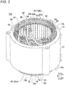
- the stator 100 has an annular shape having a central axis line C at the center thereof. Note that the stator 100 is an example of an "armature" in the claims.
- an "axial direction (axis line direction)” refers to, as shown in FIG. 1 , a direction (Z-direction) along the central axis line C of the stator 100 (a rotation axis line of a rotor 101).
- One axial side refers to a Z1-direction side
- the other axial side refers to a Z2-direction side.
- a "circumferential direction” refers to a circumferential direction (an A1-direction and an A2-direction) of the stator 100.
- a "radial direction” refers to a radial direction (R-direction) of the stator 100.
- a "radial inner side” refers to a direction (R1-direction) going toward the central axis line C of the stator 100 in the radial direction.
- a “radial outer side” refers to a direction (R2-direction) going toward the outside of the stator 100 in the radial direction.
- the stator 100 together with the rotor 101 forms a part of a rotating electrical machine 102.
- the rotating electrical machine 102 is formed as, for example, a motor, a generator, or a motor-generator.
- the stator 100 is disposed on the radial outer side of the rotor 101 provided with permanent magnets (not shown). Namely, in the present embodiment, the stator 100 forms a part of the inner-rotor rotating electrical machine 102.
- the stator 100 includes a stator core 10, sheet-type core leg part insulating members 20, and a coil part 30.
- Each core leg part insulating member 20 is disposed between a slot 12 (see FIG. 3 ) and the coil part 30 (first leg parts 71 and second leg parts 81 which will be described later) to insulate the slot 12 from the coil part 30.
- the core leg part insulating member 20 is inserted into the slot 12.
- the core leg part insulating member 20 is provided separately from an insulating layer 73 (see FIG. 8A ) which will be described later and an insulating layer 83 (see FIG. 8B ) which will be described later.
- the stator core 10 is an example of an "armature core" in the claims.
- the coil part 30 includes a first coil assembly 30a (counter-lead side coils) and a second coil assembly 30b (lead side coils).
- the coil part 30 includes a plurality of segment conductors 40 (see FIG. 4 ).
- the stator 100 includes sheet-type joint part insulating members 21 (see FIG. 4 ) provided separately from the core leg part insulating members 20.
- the stator core 10 has a cylindrical shape having the central axis line C (see FIG. 1 ) as its central axis.
- the stator core 10 is formed by, for example, axially stacking a plurality of electromagnetic steel sheets (e.g., silicon steel sheets).
- the stator core 10 is provided with a back yoke 11 having an annular shape as viewed in the axial direction; and a plurality of slots 12 provided on the radial inner side of the back yoke 11 and extending axially.
- the stator core 10 is provided with a plurality of teeth 13 on both circumferential sides of each slot 12.
- the slots 12 each are a portion surrounded by a wall part 11a of the back yoke 11 provided on the radial outer side and circumferential side surfaces 13a of two teeth 13.
- the slot 12 is provided with an opening part 12a that opens on the radial inner side.
- the slot 12 opens on both axial sides.
- the teeth 13 are formed so as to protrude toward the radial inner side from the back yoke 11.
- Each tooth 13 has projecting parts 13b formed at its tip part on the radial inner side, the projecting parts 13b making opening parts 12a of slots 12.
- the opening parts 12a each have an opening width W1 in the circumferential direction.
- the opening width W1 corresponds to a distance between tip parts of projecting parts 13b of teeth 13.
- a width W2 of a portion of a slot 12 where the coil part 30 is disposed is larger than the opening width W1.
- the slot 12 is formed as a semi-open slot.
- the width W2 corresponds to a distance between circumferential side surfaces 13a of teeth 13 disposed on both circumferential sides of the slot 12.
- the width W2 of the slot 12 is substantially constant in the radial direction.
- the coil part 30 includes rectangular conducting wires.
- the coil part 30 is made of copper or aluminum.
- the coil part 30 is formed by axially combining and joining together the first coil assembly 30a provided on the other axial side (Z2-direction side) and the second coil assembly 30b provided on one axial side (Z1-direction side).
- the first coil assembly 30a and the second coil assembly 30b each are formed in annular shape having the same central axis line C (see FIG. 1 ) as the stator core 10 at the center thereof.
- the coil part 30 is formed by joining together first leg parts 71 and second leg parts 81 (described later) of a plurality of segment conductors 40 at joint parts 90.
- the coil part 30 is formed as, for example, wave-winding coils.
- the coil part 30 is formed as 8-turn coils. Namely, the coil part 30 is formed such that eight segment conductors 40 are radially and parallelly disposed in a slot 12.
- the coil part 30 is configured to generate a magnetic flux by supplying three-phase alternating-current power thereto from a power supply part (not shown). Specifically, the coil part 30 is connected using three-phase Y connection. Namely, the coil part 30 includes a U-phase coil part 30U, a V-phase coil part 30V, and a W-phase coil part 30W. The coil part 30 is provided with a plurality of (e.g., two) neutral points N. Specifically, the coil part 30 is four parallel-connected (star-connected). Namely, the U-phase coil part 30U is provided with four neutral-point connection end parts NtU and four power-line connection end parts PtU.
- the V-phase coil part 30V is provided with four neutral-point connection end parts NtV and four power-line connection end parts PtV.
- the W-phase coil part 30W is provided with four neutral-point connection end parts NtW and four power-line connection end parts PtW. Note that in the following description, when the neutral-point connection end parts and the power-line connection end parts for the U-phase, the V-phase, and the W-phase are not particularly distinguished from each other, they are simply described as "neutral-point connection end parts Nt" and "power-line connection end parts Pt".
- the first coil assembly 30a includes a plurality of first segment conductors 70 (hereinafter, referred to as "first conductors 70") which are segment conductors 40.
- first conductors 70 Preferably, the first coil assembly 30a is formed by a combination of only a plurality of first conductors 70.
- the second coil assembly 30b includes a plurality of (e.g., three) power segment conductors 50 (hereinafter, referred to as "power conductors 50") which are segment conductors 40; a plurality of (e.g., two) neutral point segment conductors 60 (hereinafter, referred to as “neutral point conductors 60") which are segment conductors 40; and second segment conductors 80 (hereinafter, referred to as “second conductors 80") which are conductors (general segment conductors 40) different from the power conductors 50 and the neutral point conductors 60 among a plurality of segment conductors 40 and which form the coil part 30.
- power conductors 50 which are segment conductors 40
- neutral point conductors 60 which are segment conductors 40
- second conductors 80 which are conductors (general segment conductors 40) different from the power conductors 50 and the neutral point conductors 60 among a plurality of segment conductors 40 and which form the coil part 30.
- the coil part 30 includes a plurality of first conductors 70 each including a pair of first leg parts 71 extending toward one axial side (Z1-direction side) of the stator core 10.
- the plurality of first conductors 70 include first conductors 70 of a plurality of phases.
- the plurality of first conductors 70 include first conductors for the U-phase 70, first conductors for the V-phase 70, and first conductors for the W-phase 70.
- each of the plurality of first conductors 70 is disposed on the other axial side (Z2-direction side) of the stator core 10.
- the first leg parts 71 of each of the plurality of first conductors 70 have a length L1 in the axial direction.
- the coil part 30 includes a plurality of second conductors 80 each including a pair of second leg parts 81 extending toward the other axial side (Z2-direction side) of the stator core 10.
- the plurality of second conductors 80 include second conductors 80 of a plurality of phases.
- the plurality of second conductors 80 include second conductors for the U-phase 80, second conductors for the V-phase 80, and second conductors for the W-phase 80.
- each of the plurality of second conductors 80 is disposed on one axial side (Z1-direction side) of the stator core 10.
- the plurality of second conductors 80 each are disposed so as to axially face the plurality of first conductors 70.
- the second leg parts 81 of each of the plurality of second conductors 80 have a length L2 in the axial direction. Note that the length L2 of the second leg parts 81 is longer than the length L1 of the first leg parts 71.
- the coil part 30 is formed by joining together the first conductors 70 and the second conductors 80 which are two axially divided parts.
- the coil part 30 includes joint parts 90 (see FIG. 10 ) where an end part 71a on one axial side of a first leg part 71 and an end part 81a on the other axial side of a second leg part 81 are joined together in one slot 12.
- the second conductors 80 are segment conductors 40 other than the power conductors 50 and the neutral point conductors 60 among segment conductors 40 included in the second coil assembly 30b.
- the end part 71a is a portion including a first plane disposition part 71d which will be described later.
- the end part 81a is a portion including a second plane disposition part 81d which will be described later.
- each of the first conductors 70 of a plurality of phases includes a first connecting part 72 that connects together end parts 71b on the other axial side (Z2-direction side) of a pair of first leg parts 71.
- Each of the first conductors 70 of a plurality of phases is formed so as to have a U-shape (substantially U-shape) as viewed in the radial direction by connecting together a pair of first leg parts 71 disposed in different slots 12 by a first connecting part 72.
- the coil pitch of the first conductors 70 is six. Namely, a pair of first leg parts 71 are disposed at circumferentially different locations corresponding to six slots 12.
- first leg part 71 refers to a portion of the first conductor 70 that extends linearly and axially.
- first leg part 71 refers to a portion from the end part 71b to a tip part 71e of the first leg part 71 which will be described later.
- first connecting part 72 refers to a portion of the first conductor 70 other than the first leg parts 71.
- the first connecting part 72 has a bent shape that bends axially. Specifically, the first connecting part 72 has a first bent part 72a that bends at the center of the first connecting part 72. In addition, the first connecting part 72 has a pair of first diagonal parts 72b that linearly extend toward pair of first leg parts 71 sides from the first bent part 72a so as to intersect with each other. In addition, the first bent part 72a is formed in crank shape that radially bends in a stepwise manner by an amount corresponding to the width of one segment conductor 40 as viewed in the axial direction. That is, the radial width of the first bent part 72a is double the width of one segment conductor 40. Note that the expression "intersect with each other” refers to that extension lines of the first diagonal parts 72b intersect with each other on an axial outer side of the stator core 10 as viewed in the radial direction.
- the axial lengths L1 of the pair of first leg parts 71 are substantially equal to each other.
- the axial length L1 is smaller than an axial length L3 (see FIG. 2 ) of the stator core 10.
- the axial length L3 of the stator core 10 refers to an axial distance (space) between an end surface 10a and an end surface 10b in the axial direction.
- each of the second conductors 80 of a plurality of phases includes a second connecting part 82 that connects together end parts 81b on one axial side (Z1 -direction side) of a pair of second leg parts 81.
- Each of the second conductors 80 of a plurality of phases is formed so as to have a U-shape by connecting together a pair of second leg parts 81 disposed in different slots 12 by a second connecting part 82.
- the coil pitch of the second conductors 80 is six. Namely, a pair of second leg parts 81 are disposed at circumferentially different locations corresponding to six slots 12.
- the second leg part 81 refers to a portion of the second conductor 80 that extends linearly and axially.
- the second leg part 81 refers to a portion from the end part 81b to a tip part 81e of the second leg part 81 which will be described later.
- the second connecting part 82 refers to a portion of the second conductor 80 other than the second leg parts 81.
- the second connecting part 82 has a bent shape that bends axially. Specifically, the second connecting part 82 has a second bent part 82a that bends at the center of the second connecting part 82. In addition, the second connecting part 82 has a pair of second diagonal parts 82b that linearly extend toward pair of second leg parts 81 sides from the second bent part 82a so as to intersect with each other. In addition, the second bent part 82a is formed in crank shape that radially bends in a stepwise manner by an amount corresponding to the width of one segment conductor 40 as viewed in the axial direction. That is, the radial width of the second bent part 82a is double the width of one segment conductor 40.
- the axial lengths L2 of the pair of second leg parts 81 of the second conductor 80 are substantially equal to each other.
- the axial length L2 of the pair of second leg parts 81 of the second conductor 80 is larger than the axial length L1 of the pair of first leg parts 71 of the first conductor 70 (L2 > LI).
- each of a pair of first leg parts 71 is provided with an insulating layer 73.
- each segment conductor 40 (a first conductor 70 and a second conductor 80) is formed as a rectangular conducting wire whose transverse section has a substantially rectangular shape.
- a conductor surface 70a of the first conductor 70 is provided with an insulating layer 73 having a thickness t1.
- the thickness t1 of the insulating layer 73 is set to such a thickness that, for example, allows to ensure phase-to-phase insulation performance (insulation between first leg parts 71). Note that although FIG.
- the configuration is not limited to the example shown in the drawing.
- the insulating layer 73 is an example of a "first-leg-part-side insulating layer" in the claims.
- each of a pair of second leg parts 81 is provided with an insulating layer 83.
- the insulating layer 83 of the second conductor 80 is provided with an insulating layer 83 having a thickness t2.
- the thickness t2 of the insulating layer 83 is set to such a thickness that, for example, allows to ensure intra-phase insulation performance (insulation between second leg parts 81).
- FIG. 8B shows a magnitude relationship between thicknesses, etc., in an exaggerated manner for the sake of description, the configuration is not limited to the example shown in the drawing.
- the thickness t2 of the insulating layer 83 is substantially equal to the thickness t1 of the insulating layer 73.
- the insulating layer 83 is an example of a "second-leg-part-side insulating layer" in the claims.
- first leg parts 71 are arranged in one slot 12 in the radial direction of the stator core 10 (see FIG. 10 ).
- second leg parts 81 are arranged in one slot 12 in the radial direction of the stator core 10 (see FIG. 10 ).
- FIG. 10 The first figure.
- first connecting parts 72 are arranged radially on the other axial side (Z2-direction side) in a slot 12 (see FIG. 10 ).
- second connecting parts 82 are arranged radially on one axial side (Z1-direction side) in the slot 12 (see FIG. 10 ).
- a first connecting part 72 of each of a plurality of first conductors 70 is disposed so as to be adjacent to first connecting parts 72 of different phases.
- U-phase, V-phase, and W-phase segment conductors are described as U, V, and W, respectively.
- the entire pair of first diagonal parts 72b of a first connecting part 72 is provided so as to be (radially and axially) adjacent to first diagonal parts 72b of first connecting parts 72 of different phases (see FIG. 11 ).
- FIG. 18 only shows the first connecting parts 72, the second connecting parts 82 also have the same configuration and thus depiction thereof is omitted.
- a second connecting part 82 of each of a plurality of second conductors 80 is disposed so as to be adjacent to second connecting parts 82 of different phases.
- the entire pair of second diagonal parts 82b of a second connecting part 82 is provided so as to be (radially and axially) adjacent to second diagonal parts 82b of second connecting parts 82 of different phases (see FIG. 12 ).
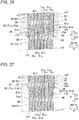
- FIG. 18A shows a state in which four portions 72e are provided on each of a pair of linear parts 72b.
- FIG. 18B as with the first connecting parts 72, each of a pair of second diagonal parts 82b is provided with portions 82e each of which is partially provided on a plane 82d facing radially and is adjacent to a second connecting part 82 of a different phase.
- second diagonal parts 82b (first diagonal parts 72b) are disposed so as to be radially shifted relative to each other (one lane changed), with a second bent part 82a (first bent part 72a) being a change point.
- second diagonal parts 82b (first diagonal parts 72b) of different phases are disposed so as to be radially and partially adjacent to each other.
- a pair of first leg parts 71 is disposed so as to be shifted relative to each other in radial location by an amount corresponding to a radial width W11 of the first leg part 71 (see FIG. 11 ).
- a pair of second leg parts 81 is disposed so as to be shifted relative to each other in radial location by an amount corresponding to a radial width W12 of the second leg part 81 (see FIG. 12 ).
- a pair of first diagonal parts 72b is disposed so as to be shifted relative to each other in radial location by an amount corresponding to the radial width W11 of the first leg part 71.
- a pair of second diagonal parts 82b is disposed so as to be shifted relative to each other in radial location by an amount corresponding to the radial width W12 of the second leg part 81.
- first diagonal parts 72b arranged radially first diagonal parts 72b other than first diagonal parts 72b provided on the innermost and outermost circumferential sides are adjacent, on their radially facing planes 72d on both sides, to first connecting parts 72 of different phases.
- second diagonal parts 82b arranged radially second diagonal parts 82b other than second diagonal parts 82b provided on the innermost and outermost circumferential sides are adjacent, on their radially facing planes 82d on both sides, to second connecting parts 82 of different phases.
- a first diagonal part 72b also has, on a plane 72f facing circumferentially (axially), a portion where the first diagonal part 72b is circumferentially (axially) adjacent to a first diagonal part 72b of a different phase.
- U1, U2, V1, V2... are arranged in this order from left to right, U2 is circumferentially (axially) adjacent to a first diagonal part 72b of V1.
- a second diagonal part 82b is also likewise provided with a plane 82f having a portion where the second diagonal part 82b is circumferentially (axially) adjacent to a second diagonal part 82b of a different phase.
- the insulation performance of the first connecting parts 72 and the second connecting parts 82 is higher than the insulation performance of the first leg parts 71 and the second leg parts 81.
- the first connecting part 72 where first connecting parts 72 of different phases are disposed so as to be adjacent to each other i.e., the first diagonal parts 72b
- an insulating layer 74 larger in thickness than the insulating layer 73 is provided with an insulating layer 74 larger in thickness than the insulating layer 73 (see FIG. 8A ).
- the insulating layer 74 is an example of a "first-connecting-part-side insulating layer" in the claims.
- the expression "the insulation performance is high” refers to that an insulatable voltage value is high.
- the insulating layer 74 includes a first base insulating layer 74a and a first added insulating layer 74c.
- the first base insulating layer 74a is integrally formed with the insulating layer 73 (see FIG. 8A ) and has a thickness t3 equal to the thickness t1 of the insulating layer 73.
- the first added insulating layer 74c is provided on a surface 74b of the first base insulating layer 74a.
- a thickness t4 of the first added insulating layer 74c is larger than the thickness t1 of the insulating layer 73 (the thickness t3 of the first base insulating layer 74a).
- the thickness t4 of the first added insulating layer 74c is about 1.5 times the thickness t1 of the insulating layer 73 (the thickness t3 of the first base insulating layer 74a). In this case, the thickness (t3 + t4) of the insulating layer 74 is about 2.5 times the thickness t1 of the insulating layer 73.
- the first added insulating layer 74c and the first base insulating layer 74a each are made of the same material (e.g., an insulating material such as polyimide) as the insulating layer 73.
- the second connecting part 82 where second connecting parts 82 of different phases are disposed so as to be adjacent to each other is provided with an insulating layer 84 larger in thickness than the insulating layer 83 (see FIG. 8B ).
- the insulating layer 84 is an example of a "second-connecting-part-side insulating layer" in the claims.
- the insulating layer 84 includes a second base insulating layer 84a and a second added insulating layer 84c.
- the second base insulating layer 84a is integrally formed with the insulating layer 83 (see FIG. 8B ) and has a thickness t5 equal to the thickness t2 of the insulating layer 83.
- the second added insulating layer 84c is provided on a surface 84b of the second base insulating layer 84a.
- a thickness t6 of the second added insulating layer 84c is larger than the thickness t2 of the insulating layer 83 (the thickness t5 of the second base insulating layer 84a).
- the thickness t6 of the second added insulating layer 84c is about 1.5 times the thickness t2 of the insulating layer 83 (the thickness t5 of the second base insulating layer 84a). In this case, the thickness (t5 + t6) of the insulating layer 84 is about 2.5 times the thickness t2 of the insulating layer 83.
- the second added insulating layer 84c and the second base insulating layer 84a each are made of the same material (e.g., an insulating material such as polyimide) as the insulating layer 83.
- the stator 100 can support high voltage.
- the insulating layer 74 (first added insulating layer 74c) is provided on each of the first bent part 72a and the pair of first diagonal parts 72b. Specifically, the insulating layer 74 (first added insulating layer 74c) is provided on a portion of the first connecting part 72 other than first inclined parts 72c which will be described later.
- the first added insulating layer 74c of the insulating layer 74 provided on the first bent part 72a and the first added insulating layer 74c of the insulating layer 74 provided on each of the pair of first diagonal parts 72b are provided integrally.
- the first added insulating layer 74c is a single insulating layer.
- the insulating layer 74 is an insulating layer that is not divided into a plurality of layers and is continuously formed on the first connecting part 72.
- the insulating layer 74 is provided so as to surround the first connecting part 72 in a circumferential manner at a cross-section (transverse section) orthogonal to a direction in which the first connecting part 72 extends.
- the insulating layer 74 has a ring shape that covers the first connecting part 72 from the radial outer side when its cross-section (transverse section) is viewed.
- the insulating layer 84 (second added insulating layer 84c) is provided on each of the second bent part 82a and the pair of second diagonal parts 82b. Specifically, the insulating layer 84 (second added insulating layer 84c) is provided on a portion of the second connecting part 82 other than second inclined parts 82c which will be described later.
- the second added insulating layer 84c of the insulating layer 84 provided on the second bent part 82a and the second added insulating layer 84c of the insulating layer 84 provided on each of the pair of second diagonal parts 82b are provided integrally.
- the second added insulating layer 84c is a single insulating layer.
- the insulating layer 84 is an insulating layer that is not divided into a plurality of layers and is continuously formed on the second connecting part 82.
- the insulating layer 84 is provided so as to surround the second connecting part 82 in a circumferential manner at a cross-section (transverse section) orthogonal to the second connecting part 82.
- the insulating layer 84 has a ring shape that covers the second connecting part 82 from the radial outer side when its cross-section (transverse section) is viewed.
- first connecting parts 72 arranged radially are provided with a first inclined part 72c.
- the first inclined part 72c is provided on an end part 71b side of a first leg part 71.
- the first inclined part 72c is inclined toward the radial outer side.
- the first inclined part 72c is provided between a portion of the first connecting part 72 provided with the insulating layer 74 and the first leg part 71 (end part 71b). Though depiction is omitted, the first inclined part 72c is provided with only the first base insulating layer 74a (see FIG. 9A ).
- first inclined part 72c is provided on those of a plurality of (eight in the present embodiment) radially arranged first connecting parts 72 other than a first connecting part 72 provided on the radial innermost side. Namely, when taking a look at a cross-section along the radial direction of the slot 12, each of the plurality of first connecting parts 72 other than the first connecting part 72 provided on the radial innermost side is offset toward the radial outer side relative to the first leg part 71. Note that in FIG. 11 , for simplification, depiction of the insulating layers 73 is omitted.
- a plurality of (seven in the present embodiment) first inclined parts 72c are arranged in the radial direction.
- a first inclined part 72c provided on the radial outer side has a greater angle of inclination ⁇ 1 with respect to the axial direction than a first inclined part 72c provided on the radial inner side.
- the angle of inclination ⁇ 1 of each of the plurality of first inclined parts 72c arranged radially gradually increases in turn from the first inclined part 72c provided on the radial innermost side.
- a second inclined part 82c is provided on an end part 81b side of a second leg part 81.
- the second inclined part 82c is inclined toward the radial outer side.
- the second inclined part 82c is provided between a portion of the second connecting part 82 provided with the insulating layer 84 and the second leg part 81 (end part 81b). Though depiction is omitted, the second inclined part 82c is provided with only the second base insulating layer 84a (see FIG. 9B ).
- the second inclined part 82c is provided on those of a plurality of (eight in the present embodiment) radially arranged second connecting parts 82 other than a second connecting part 82 provided on the radial innermost side. Namely, when taking a look at a cross-section along the radial direction of the slot 12, each of the plurality of second connecting parts 82 other than the second connecting part 82 provided on the radial innermost side is offset toward the radial outer side relative to the second leg part 81. Note that in FIG. 12 , for simplification, depiction of the insulating layers 83 is omitted.
- a plurality of (seven in the present embodiment) second inclined parts 82c are arranged in the radial direction.
- a second inclined part 82c provided on the radial outer side has a greater angle of inclination ⁇ 2 with respect to the axial direction than a second inclined part 82c provided on the radial inner side.
- the angle of inclination ⁇ 2 of each of the plurality of second inclined parts 82c arranged radially gradually increases in turn from the second inclined part 82c provided on the radial innermost side. Note that in FIGS. 11 and 12 , for simplification, depiction of the joint part insulating members 21 is omitted.
- each end part 71a includes a first plane disposition part 71d where a first plane 71c extending in the axial direction is provided.
- each end part 81a includes a second plane disposition part 81d where a second plane 81c extending in the axial direction is provided.
- a plurality of first plane disposition parts 71d and a plurality of second plane disposition parts 81d are alternately arranged in the radial direction.
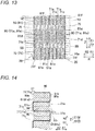
- joint parts 90 of a plurality of first leg parts 71 and a plurality of second leg parts 81 are disposed so as to be radially adjacent to each other in one slot 12. Note that in FIG. 13 , for simplification, depiction of the joint part insulating members 21 is omitted.
- a plurality of joint parts 90 are provided so as to overlap each other as viewed in the radial direction. That is, all joint parts 90 disposed in one slot 12 are disposed side by side in a horizontal direction. In other words, in one slot 12, the axial locations of the plurality of joint parts 90 are substantially equal to each other.
- the joint part 90 is a portion where the first plane 71c of the first leg part 71 (end part 71a) and the second plane 81c of the second leg part 81 (end part 81a) are joined together (overlap each other) as viewed in the radial direction.
- each of a tip part 71e of the first leg part 71 and a tip part 81e of the second leg part 81 has a tapered shape.
- each of the tip part 71e of the first leg part 71 and the tip part 81e of the second leg part 81 has a tapered shape as viewed in the circumferential direction (A-direction).
- first leg part 71 has a first leg part main body part 71f provided continuously from the first plane disposition part 71d where the first plane 71c is provided.
- the first leg part main body part 71f is provided on the opposite side (the Z2-direction side) of the first plane disposition part 71d from the tip part 71e.
- second leg part 81 has a second leg part main body part 81f provided continuously from the second plane disposition part 81d where the second plane 81c is provided.
- the second leg part main body part 81f is provided on the opposite side (the Z1-direction side) of the second plane disposition part 81d from the tip part 81e.
- a first clearance part 75 is provided between the tip part 71e of the first leg part 71 and the second leg part 81 (second leg part main body part 81f).
- a second clearance part 85 is provided between the tip part 81e of the second leg part 81 and the first leg part 71 (first leg part main body part 71f).
- a first leg part 71 of each of a plurality of first conductors 70 is disposed so as to be radially adjacent to a first leg part 71 of the same phase.
- a second leg part 81 of each of a plurality of second conductors 80 is disposed so as to be adjacent to a second leg part 81 of the same phase.
- a plurality of first leg parts 71 of the same phase are arranged radially and a plurality of second leg parts 81 of the same phase are arranged radially.
- eight first leg parts 71 disposed in one slot 12 are first leg parts 71 of the same phase.
- second leg parts 81 disposed in one slot 12 are second leg parts 81 of the same phase.
- first leg parts 71 and the second leg parts 81 disposed in one slot 12 are of the same phase. Namely, all of a plurality of first leg parts 72 and a plurality of second leg parts 82 disposed in each of the plurality of slots 12 are of the same phase. In other words, in one slot 12, leg parts (71 and 81) of different phases are not disposed so as to be adjacent to each other. Note that in the plurality of slots 12 provided circumferentially, leg parts (71 and 81) of a different phase are provided every two slots.
- the leg parts (71 and 81) are provided in order of U-phase, U-phase, V-phase, V-phase, W-phase, W-phase... (this cycle is repeated thereafter). Note that the disposition of the leg parts (71 and 81) (the arrangement of the phases) in the plurality of slots 12 is not limited thereto.
- a core leg part insulating member 20 is disposed between a wall part 11a and teeth 13 and first leg parts 71 and second leg parts 81 (segment conductors 40).
- the core leg part insulating member 20 is disposed so as to integrally cover around the plurality of second leg parts 81 disposed radially and parallelly as viewed in the Z2-direction. In other words, both circumferential sides and both radial sides of the plurality of second leg parts 81 disposed radially and parallelly are covered by the core leg part insulating member 20. By this, it becomes possible to ensure insulation between joint parts 90 and the stator core 10 by the core leg part insulating member 20.
- radially adj acent joint parts 90 are insulated from each other by a sheet-type joint part insulating member 21.
- the joint part insulating member 21 is provided separately from the core leg part insulating member 20.
- the "coil” refers to a linear portion of the coil part 30 disposed in a slot 12 after a first conductor 70 and a second conductor 80 are joined together. Thus, in one slot 12 there are disposed a plurality of coils.
- the joint part insulating member 21 is formed by, for example, folding one sheet-type insulating member such as Nomex.
- the joint part insulating member 21 includes facing surface insulating portions 21a each provided between radially adjacent joint parts 90.
- the joint part insulating member 21 includes circumferential surface insulating portions 21b each continuing from both circumferential end parts of a facing surface insulating portion 21a and covering either one of circumferential surfaces 90a of radially adjacent joint parts 90 by at least an amount corresponding to insulation distance.
- the insulation distance refers to a length in the radial direction of the circumferential surface insulating portion 21b, and a distance (creepage distance) sufficient for insulation between radially adjacent joint parts 90.
- the joint part insulating member 21 includes a portion 21c that covers a radial outer side of a joint part 90 disposed on the radial outermost side.
- the joint part insulating member 21 includes a portion 21d that covers a radial inner side of a joint part 90 disposed on the radial innermost side.
- facing surface insulating portions 21a radially adjacent to each other are connected by a circumferential surface insulating portion 21b on one or other circumferential side.
- a facing surface insulating portion 21a on the radial outer side which is one of a pair of facing surface insulating portions 21a disposed so as to be radially adjacent to each other
- a circumferential surface insulating portion 21b provided on one circumferential side a facing surface insulating portion 21a on the radial inner side which is the other one of the pair of facing surface insulating portions 21a, and a circumferential surface insulating portion 21b provided on the other circumferential side are formed in a continuous manner.
- a circumferential surface 90a on an A1-direction side of a joint part 90 and a circumferential surface 90a on an A2-direction side of a joint part 90 are alternately covered by circumferential surface insulating portions 21b.
- the joint part insulating member 21 is configured not to continuously cover circumferential surfaces 90a of a plurality of joint parts 90 disposed so as to be adjacent to each other in the radial direction.
- the joint part insulating member 21 has a meander shape (bellows shape) as viewed in the axial direction.
- all joint parts 90 in the slot 12 are insulated from each other.
- the joint part insulating member 21 is configured to be extendable in the radial direction. This is because the joint part insulating member 21 is made of a sheet-type insulating member having flexibility, and is configured not to continuously cover circumferential surfaces 90a of a plurality of joint parts 90 disposed so as to be adjacent to each other in the radial direction. By this, upon joining together a first leg part 71 and a second leg part 81, even if the first leg part 71 and the second leg part 81 are pressed in the radial direction or the axial direction, a joint part insulating member 21 can be deformed with movement of the first leg part 71 and the second leg part 81.
- each of the core leg part insulating member 20 and the joint part insulating member 21 is provided separately from the insulating layer 74 and the insulating layer 84.
- each of the core leg part insulating member 20 and the joint part insulating member 21 is provided so as to be axially separated from the insulating layer 74 and the insulating layer 84.
- a length L12 of the joint part insulating members 21 is smaller than a length L11 of the core leg part insulating members 20.
- the length L11 of the core leg part insulating members 20 is larger than the axial length L3 of the stator core 10.
- the length L12 of the joint part insulating members 21 is smaller than the length L3 of the stator core 10.
- the joint part insulating members 21 are provided so as to cover the joint parts 90 and to extend toward the Z1-directon side and the Z2-direction side from the joint parts 90.
- the length L12 of the joint part insulating members 21 is adjusted based on, for example, the magnitude of a voltage applied to the coil part 30 (based on a required creepage distance). Note that in FIG. 16 depiction of the first conductors 70 and the second conductors 80 is omitted for simplification.
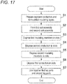
- stator 100 Next, with reference to FIG. 17 , a method of manufacturing the stator 100 will be described.
- a plurality of segment conductors 40 are prepared. Specifically, there are prepared power conductors 50 that form power-line connection end parts Pt for each phase of a Y-connected coil part 30; neutral point conductors 60 that form neutral-point connection end parts Nt for each phase of the coil part 30; and first conductors 70 and second conductors 80 that form other portions of the coil part 30.
- an insulating layer 73 and a first base insulating layer 74a are formed (coated) on a conductor surface 70a of a first conductor 70 made of a conductive material such as copper.
- the insulating layer 73 and the first base insulating layer 74a are integrally formed insulating layers. Namely, the insulating layer 73 and the first base insulating layer 74a are formed in the same process.
- an insulating layer 83 and a second base insulating layer 84a are formed (coated) on a conductor surface 80a of a second conductor 80 made of a conductive material such as copper.
- the insulating layer 83 and the second base insulating layer 84a are integrally formed insulating layers, and thus, the insulating layer 83 and the second base insulating layer 84a are formed in the same process.
- first conductors 70 and the second conductors 80 are shaped by a forming jig (not shown), by which first conductors 70 ( FIG. 6 ), second conductors 80 ( FIG. 7 ), and second leg parts 81 that form a part of power conductors 50 or a part of neutral point conductors 60 are formed.
- first inclined parts 72c are formed in each of the first conductors 70 and second inclined parts 82c are formed in each of the second conductors 80.
- the first conductors 70 and the second conductors 80 are formed such that the angle of inclination ⁇ 1 ( ⁇ 2) of a first inclined part 72c (second inclined part 82c) provided on the radial outer side is greater than the angle of inclination ⁇ 1 ( ⁇ 2) of a first inclined part 72c (second inclined part 82c) provided on the radial inner side.
- a first added insulating layer 74c is formed (coated) on a surface 74b of the first base insulating layer 74a
- a second added insulating layer 84c is formed (coated) on a surface 84b of the second base insulating layer 84a.
- possible techniques for forming the first added insulating layer 74c and the second added insulating layer 84c include, for example, a method in which a first connecting part 72 (second connecting part 82) is immersed in a liquid insulating material, a method in which an insulating material is applied to a first connecting part 72 (second connecting part 82) by spraying, etc., a method in which heat-shrink tubing is placed on a first connecting part 72 (second connecting part 82), and a method in which an insulating tape is wound around a first connecting part 72 (second connecting part 82).
- a first coil assembly 30a (see FIG. 2 ) and a second coil assembly 30b (see FIG. 2 ) each having an annular shape and including a plurality of segment conductors 40 are formed.
- the first coil assembly 30a and the second coil assembly 30b are formed such that a plurality of (e.g., eight) segment conductors 40 are disposed radially and parallelly and sets of a plurality of segment conductors 40 whose number is equal to the number of slots 12 are disposed circumferentially and parallelly.
- the power conductors 50 and the neutral point conductors 60 are disposed in the second coil assembly 30b.
- step S3 sheet-type core leg part insulating members 20 for insulating the slots 12 from the coil part 30 are inserted into the slots 12.
- step S4 the second leg parts 81 of the plurality of second conductors 80 disposed on one axial side (Z1-direction side) of the stator core 10 among the plurality of segment conductors 40 are inserted into the slots 12 of the stator core 10 from one axial side (Z1-direction side) of the stator core 10.
- the plurality of second conductors 80 are disposed on one axial side (Z1-direction side) of the stator core 10.
- a sheet-type joint part insulating member 21 is disposed between second leg parts 81 of second conductors 80 radially adjacent to each other in one slot 12 among the plurality of second conductors 80.
- step S6 the plurality of first conductors 70 are allowed to move relative to the stator core 10 from the other axial side (Z2-direction side) of the stator core 10.
- first leg parts 71 of the first conductors 70 are inserted into the slots 12.
- the plurality of first conductors 70 are disposed on the other axial side (Z2-direction side) of the stator core 10.
- first leg parts 71 of the first conductors 70 and the second leg parts 81 of the second conductors 80 are disposed in the slots 12 such that end parts 71a of the first leg parts 71 and end parts 81a of the second leg parts 81 are alternately disposed in all slots 12.
- the first leg part 71 is inserted by tilting the first leg part 71 toward the radial inner side or shifting the first leg part 71 toward the radial outer side, by which interference between the first leg part 71 and a second leg part 81 can be easily avoided.
- step S7 by radially pressing the plurality of segment conductors 40 (the end parts 71a and the end parts 81a), first planes 71c of the first leg parts 71 and second planes 81c of the second leg parts 81 are joined together.
- first leg parts 171 and second leg parts 181 are not provided with insulating layers. Note that the same components as those of the above-described first embodiment are shown in the drawings, given the same reference signs as those of the first embodiment, and description thereof is omitted.
- stator 200 is an example of an "armature" in the claims.
- the stator 200 together with the rotor 101 forms a part of a rotating electrical machine 202.
- the stator 200 includes sheet-type insulating members 120 and a coil part 130 (see FIG. 1 ).
- the coil part 130 includes a first coil assembly 130a (counter-lead side coils) (see FIG. 21 ) and a second coil assembly 130b (lead side coils) (see FIG. 21 ).
- the coil part 130 includes a plurality of segment conductors 140 (see FIG. 20 ).
- each of first conductors 170 of a plurality of phases includes a pair of first leg parts 171 and a first connecting part 172.
- the first connecting part 172 has a first bent part 172a and a pair of first diagonal parts 172b.
- each of the second conductors 180 of a plurality of phases includes a pair of second leg parts 181 (see FIG. 21 ) and a second connecting part 182 (see FIG. 21 ).
- the second connecting part 182 has a second bent part 182a (see FIG. 21 ) and a pair of second diagonal parts 182b (see FIG. 21 ).
- the first leg part 171 and the second leg part 181 have a substantially equal length (see FIG. 21 ).
- the insulation performance of the first connecting parts 172 and the second connecting parts 182 is higher than the insulation performance of the first leg parts 171 and the second leg parts 181.
- a pair of first leg parts 171 (second leg parts 181) of a segment conductor 140 is not provided with an insulating layer.
- the first leg parts 171 (second leg parts 181) are not covered with an insulating layer, and a conductor surface 140b is exposed.
- Each of at least a portion of a first connecting part 172 where first connecting parts 172 of different phases are disposed so as to be adjacent to each other, and at least a portion of a second connecting part 182 where second connecting parts 182 of different phases are disposed so as to be adjacent to each other is provided with an insulating layer.
- each of a first bent part 172a and a pair of first diagonal parts 172b of a first connecting part 172 is covered with an insulating layer 174.
- each of a second bent part 182a and a pair of second diagonal parts 182b of a second connecting part 182 is covered with an insulating layer 184 (see FIG. 21 ).
- FIG. 20 only shows the first conductor 170, the second conductor 180 is also the same and thus depiction thereof is omitted.
- the stator 200 includes, in each of a plurality of slots 12, a plate spring member 210 provided so as to be sandwiched between the coil part 130 and an opening part 12a (projecting parts 13b) of the slot 12.
- the plate spring member 210 is provided in an end space 12b provided on the radial inner side in the slot 12.
- the plate spring member 210 is made of a plate spring member that is deflectable in the R-direction.
- the plate spring member 210 is configured to maintain a contact state of contact parts 190 which will be described later, by pressing the coil part 130 from an R1-side.
- the plate spring member 210 has a plate spring shape that bends in the Z-direction. Specifically, in the plate spring member 210, a metal plate of, for example, SUS (stainless steel) that extends in the Z-direction bends in the Z-direction.
- the plate spring member 210 has a length L4 in the Z-direction smaller than a length L3 in the Z-direction of the stator core 10 (see FIG. 19 ).
- the plate spring member 210 be made of a material (e.g., Inconel (registered trademark)) that has a biasing force (elastic force) and is a non-magnetic material and has heat resistance.
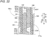
- the plate spring member 210 is configured to press the coil part 130 from the radial inner side so that a first plane 171a of a first leg part 171 of a first conductor 170 comes into contact with a second plane 181a of a second leg part 181 of a second conductor 180.
- a contact part 190 is formed.
- the contact part 190 is an example of a "joint part" in the claims.
- the first plane 171a and the second plane 181a come into contact with each other by being pressed by the plate spring member 210 without any binder between the first plane 171a and the second plane 181a. Namely, the first plane 171a and the second plane 181a are not joined together, and a contact state between the first plane 171a and the second plane 181a is maintained by a pressing force of the plate spring member 210.
- each of a plurality of contact parts 190 is disposed at a central part P1 in the axial direction of the stator core 10 in a slot 12.
- the plate spring member 210 is also disposed at the central part P1 in the axial direction of the stator core 10. Specifically, the plate spring member 210 is provided so as to overlap each of the plurality of contact parts 190 as viewed in the radial direction.
- each of the first plane 171a and the second plane 181a is subjected to a plating process. Namely, the planes (the first plane 171a and the second plane 181a) having been subjected to the plating process are in contact with each other.
- metals e.g., Ni, Ag, Au, and Sn
- the plating process may be performed using a plurality of metals (e.g., Ni and Ag) among the above-described metals.
- a first leg part 171 includes a first plane disposition part 171b, a tip part 171c, a first leg part main body part 171d, and a first step part 171e.
- a clearance part 171f is provided between the first step part 171e and a tip part 181c of a second leg part 181.
- the second leg part 181 includes a second plane disposition part 181b, the tip part 181c, a second leg part main body part 181d, and a second step part 181e.
- a clearance part 181f is provided between the second step part 181e and the tip part 171c of the first leg part 171.
- first plane disposition part 171b and the second plane disposition part 181b are provided at the central part P1 in the axial direction of the stator core 10 (see FIG. 21 ).
- the stator 200 includes insulating members 120.
- Each insulating member 120 includes an insulating layer made of a polyphenylene sulfide (PPS) resin, aramid paper, etc.
- the insulating member 120 is formed in sheet form.
- the insulating member 120 includes a first insulating part 121 for electrically insulating the stator core 10 from the coil part 130; and a second insulating part 122 for electrically insulating segment conductors 140 whose leg parts (171 and 181) are inserted into the same slot 12 from each other.
- the first insulating part 121 is provided at least between an inner surface 12c of a slot 12 and leg parts (171 and 181) in the slot 12.
- the first insulating part 121 includes a portion 121a that linearly extends around a region 12d where all segment conductors 140 in the slot 12 are disposed.
- the linearly extending portion 121a is disposed so as to surround almost the entire region 12d.
- the second insulating part 122 is provided at least between a plurality of leg parts (171 and 181) inserted into the same slot 12 in the slot 12.
- the second insulating part 122 includes a portion 122a having a meander shape and provided all the way from a segment conductor 140 disposed on the R1-side to a segment conductor 140 disposed on the R2-side in the same slot 12.
- the portion 122a having a meander shape meanders in each of segment conductors 140 adjacent to each other in the R-direction, so as to extend in the A-direction of the stator core 10 between the segment conductors 140 and extend in the R-direction between the segment conductors 140 and the inner surface 12c of the slot 12.
- the portion 122a having a meander shape includes portions 122b each extending in the A-direction of the stator core 10 between segment conductors 140; and portions 122c each extending in the R-direction between a segment conductor 140 and the inner surface 12c of the slot 12.
- a portion 122b and a portion 122c disposed on one side of the A-direction and a portion 122b and a portion 122c disposed on the other side of the A-direction are continuously formed in this order from the R1-side to the R2-side.
- the second insulating part 122 is integrally formed with the first insulating part 121 by connecting the portion 122a having a meander shape to the linearly extending portion 121a of the first insulating part 121.
- the first insulating part 121 includes an insulating layer 121b.
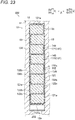
- the first insulating part 121 includes fixing layers 121d having blowing agents 121c that form foam by heat.
- the fixing layers 121d expand by formation of foam by the blowing agents 121c, by which each of the first leg parts 171 and the second leg parts 181 is fixed to the stator core 10 at least in the axial direction.
- the fixing layers 121d of the first insulating part 121 are configured to bond and fix together each of the first leg parts 171 and the second leg parts 181 and the stator core 10.
- the fixing layers 121d are provided on both surfaces of the insulating layer 121b.
- thermosetting resins 121e are cured. By this, there is no need to use varnish, etc., to fix each of the first leg parts 171 and the second leg parts 181.
- FIG. 24 to show the first insulating part 121 in an exaggerated manner, the first insulating part 121 is shown having a larger thickness than an actual thickness.
- depiction of the stator core 10, etc. is omitted for simplification.
- the second insulating part 122 also has the same configuration (composition) as the first insulating part 121.
- stator 200 Next, with reference to FIG. 25 , a method (process) of manufacturing the stator 200 will be described.
- a process of preparing segment conductors 140 is performed. Specifically, insulating layers are not provided on first leg parts 171 (second leg parts 181), and insulating layers (174, 184) are formed on first connecting parts 172 (second connecting parts 182) of first conductors 170 (second conductors 180).
- step S12 insulating members 120 are disposed (inserted) in slots 12.
- step S13 the second leg parts 181 of the second conductors 180 (see FIG. 21 ) are inserted into the slots 12 from the other axial side (Z1-direction side).
- each first leg part 171 of the first conductors 170 is inserted into the slots 12 from one axial side (Z2-direction side).
- each first leg part 171 is disposed such that a first plane 171a of the first leg part 171 and a second plane 181a of a second leg part 181 face each other.
- a plate spring member 210 (see FIG. 21 ) is inserted into an end space 12b in a slot 12 from one axial side (e.g., the Z1-direction side).
- a stator core 10 is heated and fixing layers 121d are heated, by which blowing agents 121c form foam and the fixing layers 121d expand.
- a coil part 130 is fixed to the slots 12 at least in the axial direction.
- a first connecting part (72, 172) and a second connecting part (82, 182) have a higher insulatable voltage value than a first leg part (71, 171) and a second leg part (81, 181).
- each of the first connecting part (72, 172) and the second connecting part (82, 182) can be more securely insulated.
- first leg part (71, 171) and a second leg part (81, 181) a first segment conductor (70, 170) and a second segment conductor (80, 180) are provided separately (detached) from each other.
- the first segment conductor (70, 170) by moving the first segment conductor (70, 170) to one axial side (a direction side on which the first leg part (71, 171) is provided with respect to a first connecting part (72, 172)) and moving the second segment conductor (80, 180) to the other axial side (a direction side on which the second leg part (81, 181) is provided with respect to a second connecting part (82, 182)), the first leg part (71, 171) and the second leg part (81, 181) are disposed so as to be close to each other and are joined together.
- segment conductors (40, 140) can be disposed in slots (12), with first connecting parts (72, 172) (second connecting parts (82, 182)) joined together in advance. Namely, there is no need to join together first connecting parts (72, 172) (second connecting parts (82, 182)) by a joining process such as welding after disposing segment conductors (40, 140) in slots (12). By this, damage to the connecting parts (72, 82, 172, 182) (damage to insulating layers (74, 84, 174, 184)) caused by the joining process can be prevented.
- connecting parts (72, 82, 172, 182) can be more securely insulated from each other, and damage to the connecting parts (72, 82, 172, 182) having been subjected to an insulation process (damage to insulating layers (74, 84, 174, 184)) can be prevented.
- each of a pair of first leg parts (71) is provided with a first-leg-part-side insulating layer (73), and each of a pair of second leg parts (81) is provided with a second-leg-part-side insulating layer (83).
- at least a portion of a first connecting part (72) where first connecting parts (72) of different phases are disposed so as to be adjacent to each other is provided with a first-connecting-part-side insulating layer (74) larger in thickness than the first-leg-part-side insulating layer (73).
- a second connecting part (82) where second connecting parts (82) of different phases are disposed so as to be adjacent to each other is provided with a second-connecting-part-side insulating layer (84) larger in thickness than the second-leg-part-side insulating layer (83).
- first leg part (71) and a second leg part (81) can be brought close to each other without inserting each of a first connecting part (72) and a second connecting part (82) into a slot (12), there is no need to insert a coil part (30) from the radial inner side.
- insulating layers (74, 84) of the connecting parts (72, 82) can be prevented from getting damaged by pressing from the radial inner side upon insertion from the radial inner side.
- a clearance between radially adjacent connecting parts (72, 82) which is created to form an added insulating layer (74c, 84c) can be prevented from being removed by pressing from the radial inner side upon insertion from the radial inner side.
- first segment conductors (70) and second segment conductors (80) there is no need to use a plurality of circumferentially divided armature cores (10) and to dispose leg parts (71, 81) in slots (12) by radially moving the divided armature cores (10).
- losses in the armature core (10) e.g., iron losses caused by an increase in magnetic reluctance
- first leg part (71) and a second leg part (81) can be brought close to each other without inserting each of a first connecting part (72) and a second connecting part (82) into a slot (12), there is no need to increase the top-view area of the slot (12).
- the physical size of the armature core (10) can be prevented from increasing and losses in the armature (10) can be prevented from getting worse.
- a first-connecting-part-side insulating layer (74) includes a first base insulating layer (74a) which is integrally formed with a first-leg-part-side insulating layer (73) and has a thickness (t3) equal to the thickness (t1) of the first-leg-part-side insulating layer (73); and a first added insulating layer (74c) provided on a surface (74b) of the first base insulating layer (74a).
- a second-connecting-part-side insulating layer (84) includes a second base insulating layer (84a) which is integrally formed with a second-leg-part-side insulating layer (83) and has a thickness (t5) equal to the thickness (t2) of the second-leg-part-side insulating layer (83); and a second added insulating layer (84c) provided on a surface (84b) of the second base insulating layer (84a).
- the thickness (t3 + t4) of the first-connecting-part-side insulating layer (74) can be easily made larger by the thickness (t4) of the first added insulating layer (74c) than the thickness (t1) of the first-leg-part-side insulating layer (73).
- the thickness (t5 + t6) of the second-connecting-part-side insulating layer (84) can be easily made larger by the thickness (t6) of the second added insulating layer (84c) than the thickness (t2) of the second-leg-part-side insulating layer (83).
- first leg parts (71) are arranged radially and a plurality of second leg parts (81) are arranged radially.
- a plurality of first connecting parts (72) are arranged radially on the other axial side of the slot (12).
- a plurality of second connecting parts (82) are arranged radially on one axial side of the slot (12).
- at least some of the plurality of radially arranged first connecting parts (72) each are provided with a first inclined part (72c) inclined toward one radial side between a portion of the first connecting part (72) where a first-connecting-part-side insulating layer (74) is provided and a first leg part (71).
- At least some of the plurality of radially arranged second connecting parts (82) each are provided with a second inclined part (82c) inclined toward one radial side between a portion of the second connecting part (82) where a second-connecting-part-side insulating layer (84) is provided and a second leg part (81).
- a second inclined part (82c) inclined toward one radial side between a portion of the second connecting part (82) where a second-connecting-part-side insulating layer (84) is provided and a second leg part (81).
- the size of a clearance between radially adjacent first connecting parts (71) can be easily adjusted by the angle of inclination ( ⁇ 1) of the first inclined part (72c).
- the size of a clearance between radially adjacent second connecting parts (82) can be easily adjusted by the angle of inclination ( ⁇ 2) of the second inclined part (82c).
- each of a plurality of first inclined parts (72c) and a plurality of second inclined parts (82c) is arranged radially.
- a first inclined part (72c) provided on one radial side has a greater angle of inclination ( ⁇ 1) with respect to the axial direction than a first inclined part (72c) provided on the other radial side.
- a second inclined part (82c) provided on one radial side has a greater angle of inclination ( ⁇ 2) with respect to the axial direction than a second inclined part (82c) provided on the other radial side.
- a clearance can be securely provided between adjacent first connecting parts (71), and a clearance can be securely provided between adjacent second connecting parts (82).
- a first-connecting-part-side insulating layer (74) can be easily provided in a clearance between adjacent first connecting parts (71), and a second-connecting-part-side insulating layer (84) can be easily provided in a clearance between adjacent second connecting parts (82).
- first leg parts (71) of the same phase are arranged radially and a plurality of second leg parts (81) of the same phase are arranged radially.
- first leg parts (71) can be securely insulated from each other and adjacent second leg parts (81) can be securely insulated from each other.
- the armature (100) includes sheet-type core leg part insulating members (20) provided separately from the first-leg-part-side insulating layers (73) and the second-leg-part-side insulating layers (83), and disposed between the slots (12) and the coil part (30).
- the armature (100) includes sheet-type joint part insulating members (21) each of which is provided separately from the core leg part insulating member (20) and insulates joint parts (90) radially adjacent to each other in one slot (12).
- each of the core leg part insulating members (20) and the joint part insulating members (21) is provided separately from the first-connecting-part-side insulating layers (74) and the second-connecting-part-side insulating layers (84).
- insulation properties between a slot (12) and the coil part (30) can be secured by a core leg part insulating member (20).
- insulation properties between joint parts (90) can be secured by a joint part insulating member (21).
- a first connecting part (72) has a first bent part (72a) that bends at the center of the first connecting part (72); and a pair of first diagonal parts (72b) that linearly extend toward pair of first leg parts (71) sides from the first bent part (72a).
- a second connecting part (82) has a second bent part (82a) that bends at the center of the second connecting part (82); and a pair of second diagonal parts (82b) that linearly extend toward pair of second leg parts (81) sides from the second bent part (82a).
- a first-connecting-part-side insulating layer (74) is provided on each of the first bent part (72a) and the pair of first diagonal parts (72b).
- a second-connecting-part-side insulating layer (84) is provided on each of the second bent part (82a) and the pair of second diagonal parts (82b).
- a first added insulating layer (74c) of a first-connecting-part-side insulating layer (74) provided on a first bent part (72a) and a first added insulating layer (74c) of a first-connecting-part-side insulating layer (74) provided on each of a pair of first diagonal parts (72b) are provided integrally.
- a second added insulating layer (84c) of a second-connecting-part-side insulating layer (84) provided on a second bent part (82a) and a second added insulating layer (84c) of a second-connecting-part-side insulating layer (84) provided on each of a pair of second diagonal parts (82b) are provided integrally.
- the number of parts can be reduced and the number of formation processes of the second added insulating layer (84c) can be reduced.
- a first-connecting-part-side insulating layer (74) is provided so as to surround a first connecting part (72) in a circumferential manner at a cross-section orthogonal to a direction in which the first connecting part (72) extends.
- a second-connecting-part-side insulating layer (84) is provided so as to surround a second connecting part (82) in a circumferential manner at a cross-section orthogonal to a direction in which the second connecting part (82) extends.
- first connecting part (72) compared to a case in which a part of a first connecting part (72) is covered with a first-connecting-part-side insulating layer (74) at a cross-section orthogonal to a direction in which the first connecting part (72) extends, adjacent first connecting parts (72) can be more securely insulated from each other.
- first-connecting-part-side insulating layer (74) is formed so as to cover a part of a first connecting part (72) at a cross-section orthogonal to a direction in which the first connecting part (72) extends, since there is no need to control (adjust) not to partially form a first-connecting-part-side insulating layer (74), formation of the first-connecting-part-side insulating layer (74) can be facilitated.
- adjacent second connecting parts (82) can be more securely insulated from each other.
- a second-connecting-part-side insulating layer (84) is formed so as to cover a part of a second connecting part (82) at a cross-section orthogonal to a direction in which the second connecting part (82) extends, since there is no need to control (adjust) not to partially form a second-connecting-part-side insulating layer (84), formation of the second-connecting-part-side insulating layer (84) can be facilitated.
- each of a pair of first leg parts (171) and a pair of second leg parts (181) is not provided with an insulating layer.
- at least a portion of a first connecting part (172) where first connecting parts (172) of different phases are disposed so as to be adjacent to each other and at least a portion of a second connecting part (182) where second connecting parts (182) of different phases are disposed so as to be adjacent to each other are provided with insulating layers (174, 184).
- a first connecting part (72, 172) has a first bent part (72a, 172a) that bends at the center of the first connecting part (72, 172); and a pair of first diagonal parts (72b, 172b) that extend toward pair of first leg parts (71, 171) sides from the first bent part (72a, 172a).
- a second connecting part (82, 182) has a second bent part (82a, 182a) that bends at the center of the second connecting part (82, 182); and a pair of second diagonal parts (82b, 182b) that extend toward pair of second leg parts (81, 181) sides from the second bent part (82a, 182a).
- the pair of first diagonal parts (72b and 172b) is disposed so as to extend to intersect with each other and so as to be shifted relative to each other in radial location.
- the pair of second diagonal parts (82b and 182b) is disposed so as to extend to intersect with each other and so as to be shifted relative to each other in radial location.
- at least one of the pair of first diagonal parts (72b, 172b) has a portion (72e) that is partially provided on a plane (72d) facing radially and that is adjacent to a first connecting part (72, 172) of a different phase.
- At least one of the pair of second diagonal parts (82b, 182b) has a portion (82e) that is partially provided on a plane (82d) facing radially and that is adjacent to a second connecting part (82, 182) of a different phase.
- a pair of first leg parts (71, 171) is disposed so as to be shifted relative to each other in radial location by an amount corresponding to a radial width (W11) of the first leg part (71, 171).
- a pair of second leg parts (81, 181) is disposed so as to be shifted relative to each other in radial location by an amount corresponding to a radial width (W12) of the second leg part (81, 181).
- a pair of first diagonal parts (72b, 172b) is disposed so as to be shifted relative to each other in radial location by an amount corresponding to the radial width (W 11) of the first leg part (71, 171).
- a pair of second diagonal parts (82b, 182b) is disposed so as to be shifted relative to each other in radial location by an amount corresponding to the radial width (W12) of the second leg part (81, 181).
- a pair of first leg parts (71, 171) can be disposed in radially adjacent lanes (conductor disposition regions provided in ring shape), and a pair of first diagonal parts (72b, 172b) can be disposed in radially adjacent lanes.
- a pair of second leg parts (81, 181) can be disposed in radially adjacent lanes, and a pair of second diagonal parts (82b, 182b) can be disposed in radially adjacent lanes.
- all of a plurality of first leg parts (71, 171) and a plurality of second leg parts (81, 181) that are disposed in each of the plurality of slots (12) are of the same phase.
- leg parts (71, 81, 171, 181) of different phases are not adjacent to each other, and thus, the insulation performance of the leg parts (71, 81, 171, 181) can be made relatively small.
- the present invention is not limited thereto.
- the thickness t3 of a first base insulating layer 74a may be made larger than the thickness t1 of an insulating layer 73 (first-leg-part-side insulating layer).
- the thickness t5 of a second base insulating layer 84a may be made larger than the thickness t2 of an insulating layer 83 (second-leg-part-side insulating layer).
- first bent part 72a is provided with a first added insulating layer 74c and a second bent part 82a is provided with a second added insulating layer 84c
- present invention is not limited thereto.
- first bent part 72a may not be provided with the first added insulating layer 74c
- second bent part 82a may not be provided with the second added insulating layer 84c.
- first embodiment shows an example in which the entire first diagonal part 72b is provided with a first added insulating layer 74c and the entire second diagonal part 82b is provided with a second added insulating layer 84c
- the present invention is not limited thereto.
- the portion may not be provided with a first added insulating layer 74c.
- the portion may not be provided with a second added insulating layer 84c.
- first embodiment shows an example in which those of a plurality of first connecting parts 72 arranged radially in one slot 12 other than a first connecting part 72 provided on the radial innermost side are provided with first inclined parts 72c
- the present invention is not limited thereto.
- all of the plurality of first connecting parts 72 arranged radially may be provided with first inclined parts 72c.
- all of a plurality of second connecting parts 82 arranged radially may be provided with second inclined parts 82c.
- each of a first inclined part 72c and a second inclined part 82c is inclined toward the radial outer side
- the present invention is not limited thereto.
- each of the first inclined part 72c and the second inclined part 82c may be inclined toward the radial inner side.
- the first inclined part 72c and the second inclined part 82c may be radially inclined in opposite directions.
- first-described first embodiment shows an example in which a first added insulating layer 74c of an insulating layer 74 (first-connecting-part-side insulating layer) provided on a first bent part 72a and a first added insulating layer 74c of an insulating layer 74 (first-connecting-part-side insulating layer) provided on each of a pair of first diagonal parts 72b are provided integrally, the present invention is not limited thereto.
- the first added insulating layer 74c of the insulating layer 74 (first-connecting-part-side insulating layer) and the first added insulating layer 74c of the insulating layer 74 (first-connecting-part-side insulating layer) provided on each of the pair of first diagonal parts 72b may be provided separately from each other.
- a second added insulating layer 84c of an insulating layer 84 (second-connecting-part-side insulating layer) and a second added insulating layer 84c of an insulating layer 84 (second-connecting-part-side insulating layer) provided on each of a pair of second diagonal parts 82b may be provided separately from each other.
- first added insulating layer 74c and a first base insulating layer 74a are made of the same material and a second added insulating layer 84c and a second base insulating layer 84a are made of the same material
- present invention is not limited thereto.
- the first added insulating layer 74c and the first base insulating layer 74a may be made of different materials and the second added insulating layer 84c and the second base insulating layer 84a may be made of different materials.
- first added insulating layers 74c and second added insulating layers 84c assemblies (30a, 30b) are formed
- the present invention is not limited thereto.
- first added insulating layers 74c and second added insulating layers 84c may be formed.
- first added insulating layers 74c and second added insulating layers 84c may be formed, with assemblies (30a, 30b) partially formed (with only some segment conductors (40) combined together).
- first embodiment shows an example in which a joint part 90 is disposed in a slot 12
- present invention is not limited thereto.
- a part of a joint part 90 may be disposed in a slot 12 (see FIG. 26 ).
- the entire joint part 90 may be disposed outside a slot 12 (see FIG. 27 ).
- a joint part 90 is provided on the other axial side (Z2-direction side) in a slot 12 of the stator core 10 (armature core)
- the present invention is not limited thereto.
- a joint part 90 may be provided at an axial center or on one axial side (Z1-direction side) of the stator core 10 (armature core).
- first and second embodiments show an example in which a plurality of sets of first leg parts 71 (171) and second leg parts 81 (181) are provided in a slot 12, the present invention is not limited thereto.
- the configuration may be such that only one set of a first leg part 71 (171) and a second leg part 81 (181) may be provided in a slot 12.
- first embodiment shows an example in which a pair of first leg parts 71 of a first conductor 70 has equal lengths (L1) and a pair of second leg parts 81 of a second conductor 80 has equal lengths (L2)
- the present invention is not limited thereto.
- the configuration may be such that a pair of first leg parts 271 of a first conductor 270 has different lengths (see FIG. 28A ) and a pair of second leg parts 281 of a second segment conductor 280 has different lengths (see FIG. 28B ).
- each of the first segment conductor 270 and the second segment conductor 280 has a J-shape (substantially J-shape).
- the present invention is not limited thereto.
- the length of the second leg part 81 may be shorter than the length of the first leg part 71.
- stator 100 (200) (armature) forms a part of the inner-rotor rotating electrical machine 102 (202)
- the present invention is not limited thereto.
- stator may form a part of an outer-rotor rotating electrical machine.
- first and second embodiments show an example in which a second conductor 80 (180) is a lead side conductor and a first conductor 70 (170) is a counter-lead side conductor
- the present invention is not limited thereto.
- the second conductor 80 (180) may be a counter-lead side conductor and the first conductor 70 (170) may be a lead side conductor.
- the present invention is not limited thereto.
- the present invention can also be applied to a stator including core leg part insulating members 20 and joint part insulating members 21 that are not of sheet type.
- an insulating member 120 having a bellows shape is disposed in a slot 12
- the present invention is not limited thereto.
- an insulating member having a ladder shape may be disposed in a slot 12.
- an insulating member 220 includes a first insulating part 221 and a second insulating part 222.
- the first insulating part 221 includes a ring-shaped portion 221a provided in ring shape so as to surround a region 12d where all segment conductors 140 in a slot 12 are disposed.
- the second insulating part 222 includes inter-segment-conductor portions 222a each provided between segment conductors 140 in the same slot 12 so as to extend in the circumferential direction (A-direction) of the stator core 10.
- the inter-segment-conductor portions 222a are formed continuously with the ring-shaped portion 221a.
- the ring-shaped portion 221a included in the first insulating part 221 is integrally formed with the inter-segment-conductor portions 222a included in the second insulating part 222.
- the insulating member 220 has a ladder shape as viewed in the Z-direction.
- the above-described second embodiment shows an example in which a connecting part (172, 182) is provided with an insulating layer (174, 184), the present invention is not limited thereto. If the connecting part (172, 182) has higher insulation performance (insulatable voltage value) than a leg part (171, 181), then the insulating layer (174, 184) may not be provided on the connecting part (172, 182).
Landscapes
- Engineering & Computer Science (AREA)
- Power Engineering (AREA)
- Insulation, Fastening Of Motor, Generator Windings (AREA)
- Windings For Motors And Generators (AREA)
Abstract
Description
- The present invention relates to an armature.
- Conventionally, there is known an armature including segment conductors provided with connecting parts. Such an armature is disclosed in, for example,
JP 2004-64989 A - The above-described
JP 2004-64989 A - Here, there is a case in which each of the plurality of joint-side end parts (insertion-side end parts) is disposed so as to be adjacent to a joint-side end part (insertion-side end part) of a different phase, and each of the plurality of slot inserting parts is disposed in a slot so as to be adjacent to a slot inserting part of the same phase. In this case, the joint-side end parts (insertion-side end parts) of different phases disposed so as to be adjacent to each other require high insulation performance over the slot inserting parts of the same phase disposed so as to be adjacent to each other. Hence, it is conceivable that as in the above-described
JP 2004-64989 A - Patent Literature 1:
JP 2004-64989 A - However, in a conventional armature such as that described in the above-described
JP 2004-64989 A JP 2004-64989 A - The invention is made to solve problems such as those described above, and provides an armature capable of preventing damage to connecting parts having been subjected to an insulation process, while more securely insulating the connecting parts from each other when segment conductors are disposed in an armature core in an axial direction.
- To provide the above-described armature, an armature according to a first aspect of the invention includes: an armature core provided with a plurality of slots extending in an axial direction; and a coil part including: first segment conductors of a plurality of phases each including a pair of first leg parts extending toward one axial side in the axial direction, and a first connecting part that connects together end parts on an other axial side of the pair of first leg parts; second segment conductors of a plurality of phases each including a pair of second leg parts extending toward the other axial side in the axial direction, and a second connecting part that connects together end parts on the one axial side of the pair of second leg parts; and a joint part where an end part on the one axial side of one of the first leg parts and an end part on the other axial side of one of the second leg parts are joined together in one of the slots or axially outside one of the slots, and the first leg parts of each of the plurality of first segment conductors each are disposed so as to be adjacent to the first leg part of a same phase, the second leg parts of each of the plurality of second segment conductors each are disposed so as to be adjacent to the second leg part of a same phase, the first connecting part of each of the plurality of first segment conductors is disposed so as to be adjacent to the first connecting part of a different phase, the second connecting part of each of the plurality of second segment conductors is disposed so as to be adjacent to the second connecting part of a different phase, and the first connecting part and the second connecting part have a higher insulatable voltage value than the first leg parts and the second leg parts. Note that the joint part refers to a portion in a broad sense including not only a portion where joining together is performed through a joint material, but also a portion where there is only contact without through a joint material.
- Here, connecting parts of different phases disposed so as to be adjacent to each other require high insulation performance over leg parts of the same phase disposed so as to be adjacent to each other. Thus, in the armature according to the first aspect of the invention, as described above, the first connecting part and the second connecting part have a higher insulatable voltage value than the first leg part and the second leg part, by which each of the first connecting part and the second connecting part can be more securely insulated.
- In addition, as described above, the above-described armature includes the first segment conductors and the second segment conductors. A first leg part of a first segment conductor and a second leg part of a second segment conductor are joined together. Namely, before joining together the first leg part and the second leg part, the first segment conductor and the second segment conductor are provided separately (detached) from each other. In this case, by moving the first segment conductor to one axial side (a direction side on which the first leg part is provided with respect to the first connecting part) and moving the second segment conductor to the other axial side (a direction side on which the second leg part is provided with respect to the second connecting part), the first leg part and the second leg part are disposed so as to be close to each other and are joined together. By this, without inserting each of the first connecting part and the second connecting part into a slot in the axial direction, the first leg part and the second leg part can be brought close to each other and can be joined together. As a result, since there is no passing of a connecting part through a slot, damage to a connecting part having been subjected to an insulation process (e.g., formation of an insulating coating and disposition of an insulating member) to improve insulation performance (insulatable voltage value) (damage to the insulating coating and the insulating member) can be prevented.
- In addition, in the above-described armature, unlike a case in which at least one of a first connecting part and a second connecting part is inserted into a slot in the axial direction, segment conductors can be disposed in slots, with first connecting parts (second connecting parts) joined together in advance. Namely, there is no need to join together the first connecting parts (the second connecting parts) by a joining process such as welding after disposing the segment conductors in the slots. By this, damage to the connecting parts (damage to insulating coatings and insulating members) caused by the joining process can be prevented.
- As a result of the above, when segment conductors are disposed in the armature core in the axial direction, connecting parts can be more securely insulated from each other, and damage to the connecting parts having been subjected to an insulation process can be prevented.
- An armature according to a second aspect of the invention includes: an armature core provided with a plurality of slots extending in an axial direction; and a coil part including: first segment conductors of a plurality of phases each including a pair of first leg parts extending toward one axial side in the axial direction, and a first connecting part that connects together end parts on an other axial side of the pair of first leg parts; second segment conductors of a plurality of phases each including a pair of second leg parts extending toward the other axial side in the axial direction, and a second connecting part that connects together end parts on the one axial side of the pair of second leg parts; and a joint part where an end part on the one axial side of one of the first leg parts and an end part on the other axial side of one of the second leg parts are joined together in one of the slots or axially outside one of the slots, and each of the pair of first leg parts is provided with a first-leg-part-side insulating layer, each of the pair of second leg parts is provided with a second-leg-part-side insulating layer, at least a portion of the first connecting part where the first connecting parts of different phases are disposed so as to be adjacent to each other is provided with a first-connecting-part-side insulating layer larger in thickness than the first-leg-part-side insulating layer, and at least a portion of the second connecting part where the second connecting parts of different phases are disposed so as to be adjacent to each other is provided with a second-connecting-part-side insulating layer larger in thickness than the second-leg-part-side insulating layer. Note that the joint part refers to a portion in a broad sense including not only a portion where joining together is performed through a joint material, but also a portion where there is only contact without through a joint material.
- In the armature according to the second aspect of the invention, as described above, at least a portion of a first connecting part where first connecting parts of different phases are disposed so as to be adjacent to each other is provided with a first-connecting-part-side insulating layer larger in thickness than the first-leg-part-side insulating layer, and at least a portion of a second connecting part where second connecting parts of different phases are disposed so as to be adjacent to each other is provided with a second-connecting-part-side insulating layer larger in thickness than the second-leg-part-side insulating layer. By this, each of the first connecting part and the second connecting part can be more securely insulated.
- In addition, as described above, the above-described armature includes the first segment conductors and the second segment conductors. A first leg part of a first segment conductor and a second leg part of a second segment conductor are joined together. Here, before joining together the first leg part and the second leg part, the first segment conductor and the second segment conductor are provided separately (detached) from each other. In this case, by moving the first segment conductor to one axial side (a direction side on which the first leg part is provided with respect to the first connecting part) and moving the second segment conductor to the other axial side (a direction side on which the second leg part is provided with respect to the second connecting part), the first leg part and the second leg part are disposed so as to be close to each other and are joined together. By this, without inserting each of the first connecting part and the second connecting part into a slot in the axial direction, the first leg part and the second leg part can be brought close to each other and can be joined together. As a result, since there is no passing of a connecting part through a slot, damage to the connecting part (damage to a first-connecting-part-side insulating layer and a second-connecting-part-side insulating layer) can be prevented.
- In addition, in the above-described armature, unlike a case in which at least one of a first connecting part and a second connecting part is inserted into a slot in the axial direction, segment conductors can be disposed in slots, with first connecting parts (second connecting parts) joined together in advance. Namely, there is no need to join together the first connecting parts (the second connecting parts) by a joining process such as welding after disposing the segment conductors in the slots. By this, damage to the connecting parts (damage to a first-connecting-part-side insulating layer and a second-connecting-part-side insulating layer) caused by the joining process can be prevented.
- As a result of the above, when segment conductors are disposed in the armature core in the axial direction, connecting parts can be more securely insulated from each other, and damage to the connecting parts (damage to a first-connecting-part-side insulating layer and a second-connecting-part-side insulating layer) can be prevented.
- In addition, compared to a case in which at least one of a first connecting part and a second connecting part is inserted into a slot in the axial direction, an increase in the axial opening area of the slot can be prevented, and an increase in the size of the armature core can be prevented. By this, in a case in which a first segment conductor and a second segment conductor are disposed in the armature core in the axial direction, even when the thickness of a first-connecting-part-side insulating layer is larger than the thickness of a first-leg-part-side insulating layer and the thickness of a second-connecting-part-side insulating layer is larger than the thickness of a second-leg-part-side insulating layer, compared to a case in which at least one of a first connecting part and a second connecting part is inserted into a slot in the axial direction, an increase in the size of the armature core can be prevented.
- In addition, since a first leg part and a second leg part can be brought close to each other without inserting each of a first connecting part and a second connecting part into a slot, there is no need to insert a coil part from the radial inner side. As a result, the insulating layers of the connecting parts can be prevented from getting damaged by pressing from the radial inner side upon insertion from the radial inner side. In addition, by axially moving each of the first segment conductors and the second segment conductors, there is no need to use a plurality of armature cores which are divided circumferentially and to dispose the leg parts in the slots by radially moving the divided armature cores. As a result, compared to a case in the armature core is divided, losses in the armature core (e.g., iron losses caused by an increase in magnetic reluctance) can be prevented from getting worse.
- In addition, since a first leg part and a second leg part can be brought close to each other without inserting each of a first connecting part and a second connecting part into a slot, there is no need to increase the top-view area of the slot. As a result, the physical size of the armature core can be prevented from increasing and losses in the armature can be prevented from getting worse.
- According to the present invention, as described above, when segment conductors are disposed in an armature core in an axial direction, connecting parts can be more securely insulated from each other, and damage to the connecting parts having been subjected to an insulation process can be prevented.
-
-
FIG. 1 is a plan view showing a configuration of a stator (rotating electrical machine) according to first and second embodiments. -
FIG. 2 is a perspective view showing a configuration of the stator according to the first embodiment. -
FIG. 3 is an enlarged partial plan view showing a configuration of a stator core according to the first and second embodiments. -
FIG. 4 is an enlarged partial cross-sectional view showing configurations of a core leg part insulating member and a joint part insulating member according to the first embodiment. -
FIG. 5 is a circuit diagram showing a connection configuration of a coil part according to the first embodiment. -
FIG. 6 is a front view showing a configuration of a first conductor according to the first embodiment. -
FIG. 7 is a front view showing a configuration of a second conductor according to the first embodiment. -
FIG. 8 is transverse cross-sectional views showing configurations of leg parts according to the first embodiment (FIG. 8A is a transverse cross-sectional view of a first leg part andFIG. 8B is a transverse cross-sectional view of a second leg part). -
FIG. 9 is transverse cross-sectional views showing configurations of connecting parts according to the first embodiment (FIG. 9A is a transverse cross-sectional view of a first connecting part andFIG. 9B is a transverse cross-sectional view of a second connecting part). -
FIG. 10 is a cross-sectional view taken along line 1000-1000 ofFIG. 1 . -
FIG. 11 is a partial enlarged view of a portion near first connecting parts ofFIG. 10 . -
FIG. 12 is a partial enlarged view of a portion near second connecting parts ofFIG. 10 . -
FIG. 13 is a partial enlarged view of a portion near joint parts ofFIG. 10 . -
FIG. 14 is a cross-sectional view showing a configuration of the joint part insulating member according to the first embodiment. -
FIG. 15 is a perspective view showing a configuration of the joint part insulating member according to the first embodiment. -
FIG. 16 is an exploded perspective view in which the stator core, the core leg part insulating members, and the joint part insulating members according to the first embodiment are separated. -
FIG. 17 is a flowchart for describing a method of manufacturing the stator according to the first embodiment. -
FIG. 18 is a diagram for describing configurations of the connecting parts according to the first embodiment (FIG. 18A is a diagram of first segment conductors disposed in slots as viewed from a radial inner side,FIG. 18B is a diagram of second segment conductors disposed in slots as viewed from the radial inner side, andFIG. 18C is an enlarged partial plan view of a portion near connecting parts). -
FIG. 19 is an exploded perspective view of a stator according to the second embodiment. -
FIG. 20 is a cross-sectional view of a segment conductor according to the second embodiment. -
FIG. 21 is a cross-sectional view of the inside of a slot taken along a radial direction according to the second embodiment. -
FIG. 22 is an enlarged partial view of a portion near a contact part ofFIG. 21 . -
FIG. 23 is a cross-sectional view showing a configuration of an insulating member according to the second embodiment. -
FIG. 24 is a cross-sectional view showing configurations of an insulating layer and fixing layers of the insulating member according to the second embodiment. -
FIG. 25 is a flowchart showing a method of manufacturing the stator according to the second embodiment. -
FIG. 26 is a partial enlarged view of a portion near joint parts of a stator according to a first variant of the first embodiment. -
FIG. 27 is a partial enlarged view of a portion near joint parts of a stator according to a second variant of the first embodiment. -
FIG. 28 is perspective views of a first conductor and a second conductor according to a third variant of the first embodiment (FIG. 28A is a perspective view of the first conductor as viewed from a radial outer side andFIG. 28B is a perspective view of the second conductor as viewed from the radial outer side). -
FIG. 29 is a cross-sectional view showing a configuration of an insulating member according to a fourth variant of the second embodiment. - The present embodiments of the present invention will be described below based on the drawings.
- With reference to
FIGS. 1 to 17 , a structure of astator 100 according to the present embodiment will be described. Thestator 100 has an annular shape having a central axis line C at the center thereof. Note that thestator 100 is an example of an "armature" in the claims. - In the specification of this application, an "axial direction (axis line direction)" refers to, as shown in
FIG. 1 , a direction (Z-direction) along the central axis line C of the stator 100 (a rotation axis line of a rotor 101). One axial side refers to a Z1-direction side, and the other axial side refers to a Z2-direction side. In addition, a "circumferential direction" refers to a circumferential direction (an A1-direction and an A2-direction) of thestator 100. In addition, a "radial direction" refers to a radial direction (R-direction) of thestator 100. In addition, a "radial inner side" refers to a direction (R1-direction) going toward the central axis line C of thestator 100 in the radial direction. In addition, a "radial outer side" refers to a direction (R2-direction) going toward the outside of thestator 100 in the radial direction. - The
stator 100 together with therotor 101 forms a part of a rotatingelectrical machine 102. The rotatingelectrical machine 102 is formed as, for example, a motor, a generator, or a motor-generator. As shown inFIG. 1 , thestator 100 is disposed on the radial outer side of therotor 101 provided with permanent magnets (not shown). Namely, in the present embodiment, thestator 100 forms a part of the inner-rotor rotatingelectrical machine 102. - As shown in
FIG. 2 , thestator 100 includes astator core 10, sheet-type core legpart insulating members 20, and acoil part 30. Each core legpart insulating member 20 is disposed between a slot 12 (seeFIG. 3 ) and the coil part 30 (first leg parts 71 andsecond leg parts 81 which will be described later) to insulate theslot 12 from thecoil part 30. Namely, the core legpart insulating member 20 is inserted into theslot 12. The core legpart insulating member 20 is provided separately from an insulating layer 73 (seeFIG. 8A ) which will be described later and an insulating layer 83 (seeFIG. 8B ) which will be described later. Note that thestator core 10 is an example of an "armature core" in the claims. - In addition, the
coil part 30 includes afirst coil assembly 30a (counter-lead side coils) and asecond coil assembly 30b (lead side coils). In addition, thecoil part 30 includes a plurality of segment conductors 40 (seeFIG. 4 ). In addition, thestator 100 includes sheet-type joint part insulating members 21 (seeFIG. 4 ) provided separately from the core legpart insulating members 20. - The
stator core 10 has a cylindrical shape having the central axis line C (seeFIG. 1 ) as its central axis. In addition, thestator core 10 is formed by, for example, axially stacking a plurality of electromagnetic steel sheets (e.g., silicon steel sheets). As shown inFIG. 3 , thestator core 10 is provided with aback yoke 11 having an annular shape as viewed in the axial direction; and a plurality ofslots 12 provided on the radial inner side of theback yoke 11 and extending axially. Thestator core 10 is provided with a plurality ofteeth 13 on both circumferential sides of eachslot 12. - The
slots 12 each are a portion surrounded by awall part 11a of theback yoke 11 provided on the radial outer side and circumferential side surfaces 13a of twoteeth 13. Theslot 12 is provided with anopening part 12a that opens on the radial inner side. In addition, theslot 12 opens on both axial sides. Theteeth 13 are formed so as to protrude toward the radial inner side from theback yoke 11. Eachtooth 13 has projectingparts 13b formed at its tip part on the radial inner side, the projectingparts 13b makingopening parts 12a ofslots 12. - The opening
parts 12a each have an opening width W1 in the circumferential direction. Here, the opening width W1 corresponds to a distance between tip parts of projectingparts 13b ofteeth 13. In addition, a width W2 of a portion of aslot 12 where thecoil part 30 is disposed is larger than the opening width W1. Namely, theslot 12 is formed as a semi-open slot. Here, the width W2 corresponds to a distance between circumferential side surfaces 13a ofteeth 13 disposed on both circumferential sides of theslot 12. In addition, the width W2 of theslot 12 is substantially constant in the radial direction. - As shown in
FIG. 4 , thecoil part 30 includes rectangular conducting wires. For example, thecoil part 30 is made of copper or aluminum. - In addition, as shown in
FIG. 2 , thecoil part 30 is formed by axially combining and joining together thefirst coil assembly 30a provided on the other axial side (Z2-direction side) and thesecond coil assembly 30b provided on one axial side (Z1-direction side). Thefirst coil assembly 30a and thesecond coil assembly 30b each are formed in annular shape having the same central axis line C (seeFIG. 1 ) as thestator core 10 at the center thereof. In addition, as shown inFIG. 4 , in the present embodiment, thecoil part 30 is formed by joining togetherfirst leg parts 71 and second leg parts 81 (described later) of a plurality ofsegment conductors 40 atjoint parts 90. - The
coil part 30 is formed as, for example, wave-winding coils. In addition, thecoil part 30 is formed as 8-turn coils. Namely, thecoil part 30 is formed such that eightsegment conductors 40 are radially and parallelly disposed in aslot 12. - As shown in
FIG. 5 , thecoil part 30 is configured to generate a magnetic flux by supplying three-phase alternating-current power thereto from a power supply part (not shown). Specifically, thecoil part 30 is connected using three-phase Y connection. Namely, thecoil part 30 includes aU-phase coil part 30U, a V-phase coil part 30V, and a W-phase coil part 30W. Thecoil part 30 is provided with a plurality of (e.g., two) neutral points N. Specifically, thecoil part 30 is four parallel-connected (star-connected). Namely, theU-phase coil part 30U is provided with four neutral-point connection end parts NtU and four power-line connection end parts PtU. The V-phase coil part 30V is provided with four neutral-point connection end parts NtV and four power-line connection end parts PtV. The W-phase coil part 30W is provided with four neutral-point connection end parts NtW and four power-line connection end parts PtW. Note that in the following description, when the neutral-point connection end parts and the power-line connection end parts for the U-phase, the V-phase, and the W-phase are not particularly distinguished from each other, they are simply described as "neutral-point connection end parts Nt" and "power-line connection end parts Pt". - As shown in
FIG. 2 , thefirst coil assembly 30a includes a plurality of first segment conductors 70 (hereinafter, referred to as "first conductors 70") which aresegment conductors 40. Preferably, thefirst coil assembly 30a is formed by a combination of only a plurality offirst conductors 70. - In addition, the
second coil assembly 30b includes a plurality of (e.g., three) power segment conductors 50 (hereinafter, referred to as "power conductors 50") which aresegment conductors 40; a plurality of (e.g., two) neutral point segment conductors 60 (hereinafter, referred to as "neutral point conductors 60") which aresegment conductors 40; and second segment conductors 80 (hereinafter, referred to as "second conductors 80") which are conductors (general segment conductors 40) different from thepower conductors 50 and theneutral point conductors 60 among a plurality ofsegment conductors 40 and which form thecoil part 30. Namely, all of thepower conductors 50 and theneutral point conductors 60 provided in thestator 100 are provided in thesecond coil assembly 30b. - As shown in
FIG. 6 , thecoil part 30 includes a plurality offirst conductors 70 each including a pair offirst leg parts 71 extending toward one axial side (Z1-direction side) of thestator core 10. The plurality offirst conductors 70 includefirst conductors 70 of a plurality of phases. Specifically, the plurality offirst conductors 70 include first conductors for the U-phase 70, first conductors for the V-phase 70, and first conductors for the W-phase 70. In addition, each of the plurality offirst conductors 70 is disposed on the other axial side (Z2-direction side) of thestator core 10. In addition, thefirst leg parts 71 of each of the plurality offirst conductors 70 have a length L1 in the axial direction. - In addition, as shown in
FIG. 7 , thecoil part 30 includes a plurality ofsecond conductors 80 each including a pair ofsecond leg parts 81 extending toward the other axial side (Z2-direction side) of thestator core 10. The plurality ofsecond conductors 80 includesecond conductors 80 of a plurality of phases. Specifically, the plurality ofsecond conductors 80 include second conductors for the U-phase 80, second conductors for the V-phase 80, and second conductors for the W-phase 80. In addition, each of the plurality ofsecond conductors 80 is disposed on one axial side (Z1-direction side) of thestator core 10. In addition, the plurality ofsecond conductors 80 each are disposed so as to axially face the plurality offirst conductors 70. In addition, thesecond leg parts 81 of each of the plurality ofsecond conductors 80 have a length L2 in the axial direction. Note that the length L2 of thesecond leg parts 81 is longer than the length L1 of thefirst leg parts 71. - In addition, the
coil part 30 is formed by joining together thefirst conductors 70 and thesecond conductors 80 which are two axially divided parts. Specifically, thecoil part 30 includes joint parts 90 (seeFIG. 10 ) where anend part 71a on one axial side of afirst leg part 71 and anend part 81a on the other axial side of asecond leg part 81 are joined together in oneslot 12. Here, thesecond conductors 80 aresegment conductors 40 other than thepower conductors 50 and theneutral point conductors 60 amongsegment conductors 40 included in thesecond coil assembly 30b. Note that theend part 71a is a portion including a firstplane disposition part 71d which will be described later. In addition, theend part 81a is a portion including a secondplane disposition part 81d which will be described later. - As shown in
FIG. 6 , each of thefirst conductors 70 of a plurality of phases includes a first connectingpart 72 that connects together endparts 71b on the other axial side (Z2-direction side) of a pair offirst leg parts 71. Each of thefirst conductors 70 of a plurality of phases is formed so as to have a U-shape (substantially U-shape) as viewed in the radial direction by connecting together a pair offirst leg parts 71 disposed indifferent slots 12 by a first connectingpart 72. The coil pitch of thefirst conductors 70 is six. Namely, a pair offirst leg parts 71 are disposed at circumferentially different locations corresponding to sixslots 12. Namely, fiveslots 12 are provided between aslot 12 in which afirst leg part 71 which is one of a pair offirst leg parts 71 is disposed and aslot 12 in which the otherfirst leg part 71 is disposed. Note that thefirst leg part 71 refers to a portion of thefirst conductor 70 that extends linearly and axially. Specifically, thefirst leg part 71 refers to a portion from theend part 71b to atip part 71e of thefirst leg part 71 which will be described later. In addition, the first connectingpart 72 refers to a portion of thefirst conductor 70 other than thefirst leg parts 71. - In addition, the first connecting
part 72 has a bent shape that bends axially. Specifically, the first connectingpart 72 has a firstbent part 72a that bends at the center of the first connectingpart 72. In addition, the first connectingpart 72 has a pair of firstdiagonal parts 72b that linearly extend toward pair offirst leg parts 71 sides from the firstbent part 72a so as to intersect with each other. In addition, the firstbent part 72a is formed in crank shape that radially bends in a stepwise manner by an amount corresponding to the width of onesegment conductor 40 as viewed in the axial direction. That is, the radial width of the firstbent part 72a is double the width of onesegment conductor 40. Note that the expression "intersect with each other" refers to that extension lines of the firstdiagonal parts 72b intersect with each other on an axial outer side of thestator core 10 as viewed in the radial direction. - In addition, the axial lengths L1 of the pair of
first leg parts 71 are substantially equal to each other. In addition, the axial length L1 is smaller than an axial length L3 (seeFIG. 2 ) of thestator core 10. Note that the axial length L3 of thestator core 10 refers to an axial distance (space) between anend surface 10a and anend surface 10b in the axial direction. - Likewise, as shown in
FIG. 7 , each of thesecond conductors 80 of a plurality of phases includes a second connectingpart 82 that connects together endparts 81b on one axial side (Z1 -direction side) of a pair ofsecond leg parts 81. Each of thesecond conductors 80 of a plurality of phases is formed so as to have a U-shape by connecting together a pair ofsecond leg parts 81 disposed indifferent slots 12 by a second connectingpart 82. The coil pitch of thesecond conductors 80 is six. Namely, a pair ofsecond leg parts 81 are disposed at circumferentially different locations corresponding to sixslots 12. Namely, fiveslots 12 are provided between aslot 12 in which asecond leg part 81 which is one of a pair ofsecond leg parts 81 is disposed and aslot 12 in which the othersecond leg part 81 is disposed. Note that thesecond leg part 81 refers to a portion of thesecond conductor 80 that extends linearly and axially. Specifically, thesecond leg part 81 refers to a portion from theend part 81b to atip part 81e of thesecond leg part 81 which will be described later. In addition, the second connectingpart 82 refers to a portion of thesecond conductor 80 other than thesecond leg parts 81. - In addition, the second connecting
part 82 has a bent shape that bends axially. Specifically, the second connectingpart 82 has a secondbent part 82a that bends at the center of the second connectingpart 82. In addition, the second connectingpart 82 has a pair of seconddiagonal parts 82b that linearly extend toward pair ofsecond leg parts 81 sides from the secondbent part 82a so as to intersect with each other. In addition, the secondbent part 82a is formed in crank shape that radially bends in a stepwise manner by an amount corresponding to the width of onesegment conductor 40 as viewed in the axial direction. That is, the radial width of the secondbent part 82a is double the width of onesegment conductor 40. - In addition, the axial lengths L2 of the pair of
second leg parts 81 of thesecond conductor 80 are substantially equal to each other. In addition, the axial length L2 of the pair ofsecond leg parts 81 of thesecond conductor 80 is larger than the axial length L1 of the pair offirst leg parts 71 of the first conductor 70 (L2 > LI). - In addition, as shown in
FIG. 8A , each of a pair offirst leg parts 71 is provided with an insulatinglayer 73. Specifically, each segment conductor 40 (afirst conductor 70 and a second conductor 80) is formed as a rectangular conducting wire whose transverse section has a substantially rectangular shape. Aconductor surface 70a of thefirst conductor 70 is provided with an insulatinglayer 73 having a thickness t1. The thickness t1 of the insulatinglayer 73 is set to such a thickness that, for example, allows to ensure phase-to-phase insulation performance (insulation between first leg parts 71). Note that althoughFIG. 8A shows a magnitude relationship between thicknesses, etc., in an exaggerated manner for the sake of description, the configuration is not limited to the example shown in the drawing. In addition, the insulatinglayer 73 is an example of a "first-leg-part-side insulating layer" in the claims. - In addition, as shown in
FIG. 8B , each of a pair ofsecond leg parts 81 is provided with an insulatinglayer 83. Specifically, the insulatinglayer 83 of thesecond conductor 80 is provided with an insulatinglayer 83 having a thickness t2. The thickness t2 of the insulatinglayer 83 is set to such a thickness that, for example, allows to ensure intra-phase insulation performance (insulation between second leg parts 81). Note that althoughFIG. 8B shows a magnitude relationship between thicknesses, etc., in an exaggerated manner for the sake of description, the configuration is not limited to the example shown in the drawing. In addition, the thickness t2 of the insulatinglayer 83 is substantially equal to the thickness t1 of the insulatinglayer 73. Note that the insulatinglayer 83 is an example of a "second-leg-part-side insulating layer" in the claims. - In addition, a plurality of
first leg parts 71 are arranged in oneslot 12 in the radial direction of the stator core 10 (seeFIG. 10 ). In addition, a plurality ofsecond leg parts 81 are arranged in oneslot 12 in the radial direction of the stator core 10 (see -
FIG. 10 ). - Specifically, a plurality of first connecting
parts 72 are arranged radially on the other axial side (Z2-direction side) in a slot 12 (seeFIG. 10 ). In addition, a plurality of second connectingparts 82 are arranged radially on one axial side (Z1-direction side) in the slot 12 (seeFIG. 10 ). - Here, as shown in
FIG. 18 , a first connectingpart 72 of each of a plurality offirst conductors 70 is disposed so as to be adjacent to first connectingparts 72 of different phases. InFIG. 18 , U-phase, V-phase, and W-phase segment conductors are described as U, V, and W, respectively. Specifically, the entire pair of firstdiagonal parts 72b of a first connectingpart 72 is provided so as to be (radially and axially) adjacent to firstdiagonal parts 72b of first connectingparts 72 of different phases (seeFIG. 11 ). Note that althoughFIG. 18 only shows the first connectingparts 72, the second connectingparts 82 also have the same configuration and thus depiction thereof is omitted. - In addition, as shown in
FIG. 7 , a second connectingpart 82 of each of a plurality ofsecond conductors 80 is disposed so as to be adjacent to second connectingparts 82 of different phases. Specifically, the entire pair of seconddiagonal parts 82b of a second connectingpart 82 is provided so as to be (radially and axially) adjacent to seconddiagonal parts 82b of second connectingparts 82 of different phases (seeFIG. 12 ). - As shown in
FIG. 18A , at least one of a pair of firstdiagonal parts 72b hasportions 72e (hatched portions ofFIG. 18A ) each of which is partially provided on aplane 72d facing radially and is adjacent to a first connectingpart 72 of a different phase.FIG. 18A shows a state in which fourportions 72e are provided on each of a pair oflinear parts 72b. In addition, as shown inFIG. 18B , as with the first connectingparts 72, each of a pair of seconddiagonal parts 82b is provided withportions 82e each of which is partially provided on aplane 82d facing radially and is adjacent to a second connectingpart 82 of a different phase. - This results from the fact that, as shown in
FIG. 18C , seconddiagonal parts 82b (firstdiagonal parts 72b) are disposed so as to be radially shifted relative to each other (one lane changed), with a secondbent part 82a (firstbent part 72a) being a change point. By this, seconddiagonal parts 82b (firstdiagonal parts 72b) of different phases are disposed so as to be radially and partially adjacent to each other. - Specifically, a pair of
first leg parts 71 is disposed so as to be shifted relative to each other in radial location by an amount corresponding to a radial width W11 of the first leg part 71 (seeFIG. 11 ). In addition, a pair ofsecond leg parts 81 is disposed so as to be shifted relative to each other in radial location by an amount corresponding to a radial width W12 of the second leg part 81 (seeFIG. 12 ). In addition, a pair of firstdiagonal parts 72b is disposed so as to be shifted relative to each other in radial location by an amount corresponding to the radial width W11 of thefirst leg part 71. A pair of seconddiagonal parts 82b is disposed so as to be shifted relative to each other in radial location by an amount corresponding to the radial width W12 of thesecond leg part 81. - In addition, of a plurality of first
diagonal parts 72b arranged radially, firstdiagonal parts 72b other than firstdiagonal parts 72b provided on the innermost and outermost circumferential sides are adjacent, on theirradially facing planes 72d on both sides, to first connectingparts 72 of different phases. In addition, of a plurality of seconddiagonal parts 82b arranged radially, seconddiagonal parts 82b other than seconddiagonal parts 82b provided on the innermost and outermost circumferential sides are adjacent, on theirradially facing planes 82d on both sides, to second connectingparts 82 of different phases. - In addition, a first
diagonal part 72b also has, on a plane 72f facing circumferentially (axially), a portion where the firstdiagonal part 72b is circumferentially (axially) adjacent to a firstdiagonal part 72b of a different phase. Specifically, as shown inFIG. 18A , since U1, U2, V1, V2... are arranged in this order from left to right, U2 is circumferentially (axially) adjacent to a firstdiagonal part 72b of V1. In addition, as shown inFIG. 18B , a seconddiagonal part 82b is also likewise provided with aplane 82f having a portion where the seconddiagonal part 82b is circumferentially (axially) adjacent to a seconddiagonal part 82b of a different phase. - Here, in the present embodiment, as shown in
FIG. 6 , the insulation performance of the first connectingparts 72 and the second connectingparts 82 is higher than the insulation performance of thefirst leg parts 71 and thesecond leg parts 81. Specifically, at least a portion of the first connectingpart 72 where first connectingparts 72 of different phases are disposed so as to be adjacent to each other (i.e., the firstdiagonal parts 72b) is provided with an insulatinglayer 74 larger in thickness than the insulating layer 73 (seeFIG. 8A ). Note that the insulatinglayer 74 is an example of a "first-connecting-part-side insulating layer" in the claims. In addition, the expression "the insulation performance is high" refers to that an insulatable voltage value is high. - Specifically, as shown in
FIG. 9A , the insulatinglayer 74 includes a firstbase insulating layer 74a and a first added insulatinglayer 74c. The firstbase insulating layer 74a is integrally formed with the insulating layer 73 (seeFIG. 8A ) and has a thickness t3 equal to the thickness t1 of the insulatinglayer 73. The first added insulatinglayer 74c is provided on asurface 74b of the firstbase insulating layer 74a. A thickness t4 of the first added insulatinglayer 74c is larger than the thickness t1 of the insulating layer 73 (the thickness t3 of the firstbase insulating layer 74a). For example, the thickness t4 of the first added insulatinglayer 74c is about 1.5 times the thickness t1 of the insulating layer 73 (the thickness t3 of the firstbase insulating layer 74a). In this case, the thickness (t3 + t4) of the insulatinglayer 74 is about 2.5 times the thickness t1 of the insulatinglayer 73. Note that the first added insulatinglayer 74c and the firstbase insulating layer 74a each are made of the same material (e.g., an insulating material such as polyimide) as the insulatinglayer 73. - In addition, as shown in
FIG. 7 , at least a portion of the second connectingpart 82 where second connectingparts 82 of different phases are disposed so as to be adjacent to each other (i.e., the seconddiagonal parts 82b) is provided with an insulatinglayer 84 larger in thickness than the insulating layer 83 (seeFIG. 8B ). Note that the insulatinglayer 84 is an example of a "second-connecting-part-side insulating layer" in the claims. - Specifically, as shown in
FIG. 9B , the insulatinglayer 84 includes a secondbase insulating layer 84a and a second added insulatinglayer 84c. The secondbase insulating layer 84a is integrally formed with the insulating layer 83 (seeFIG. 8B ) and has a thickness t5 equal to the thickness t2 of the insulatinglayer 83. The second added insulatinglayer 84c is provided on asurface 84b of the secondbase insulating layer 84a. A thickness t6 of the second added insulatinglayer 84c is larger than the thickness t2 of the insulating layer 83 (the thickness t5 of the secondbase insulating layer 84a). For example, the thickness t6 of the second added insulatinglayer 84c is about 1.5 times the thickness t2 of the insulating layer 83 (the thickness t5 of the secondbase insulating layer 84a). In this case, the thickness (t5 + t6) of the insulatinglayer 84 is about 2.5 times the thickness t2 of the insulatinglayer 83. Note that the second added insulatinglayer 84c and the secondbase insulating layer 84a each are made of the same material (e.g., an insulating material such as polyimide) as the insulatinglayer 83. - As described above, by providing the first added insulating
layer 74c (second added insulatinglayer 84c) on the first connecting part 72 (second connecting part 82) having a relatively large voltage difference between different phases, thestator 100 can support high voltage. - In addition, in the present embodiment, as shown in
FIG. 6 , the insulating layer 74 (first added insulatinglayer 74c) is provided on each of the firstbent part 72a and the pair of firstdiagonal parts 72b. Specifically, the insulating layer 74 (first added insulatinglayer 74c) is provided on a portion of the first connectingpart 72 other than firstinclined parts 72c which will be described later. - In addition, the first added insulating
layer 74c of the insulatinglayer 74 provided on the firstbent part 72a and the first added insulatinglayer 74c of the insulatinglayer 74 provided on each of the pair of firstdiagonal parts 72b are provided integrally. Specifically, the first added insulatinglayer 74c is a single insulating layer. In other words, the insulatinglayer 74 is an insulating layer that is not divided into a plurality of layers and is continuously formed on the first connectingpart 72. - In addition, as shown in
FIG. 9A , the insulatinglayer 74 is provided so as to surround the first connectingpart 72 in a circumferential manner at a cross-section (transverse section) orthogonal to a direction in which the first connectingpart 72 extends. Namely, the insulatinglayer 74 has a ring shape that covers the first connectingpart 72 from the radial outer side when its cross-section (transverse section) is viewed. - In addition, in the present embodiment, as shown in
FIG. 7 , the insulating layer 84 (second added insulatinglayer 84c) is provided on each of the secondbent part 82a and the pair of seconddiagonal parts 82b. Specifically, the insulating layer 84 (second added insulatinglayer 84c) is provided on a portion of the second connectingpart 82 other than secondinclined parts 82c which will be described later. - In addition, the second added insulating
layer 84c of the insulatinglayer 84 provided on the secondbent part 82a and the second added insulatinglayer 84c of the insulatinglayer 84 provided on each of the pair of seconddiagonal parts 82b are provided integrally. Specifically, the second added insulatinglayer 84c is a single insulating layer. In other words, the insulatinglayer 84 is an insulating layer that is not divided into a plurality of layers and is continuously formed on the second connectingpart 82. - In addition, as shown in
FIG. 9B , the insulatinglayer 84 is provided so as to surround the second connectingpart 82 in a circumferential manner at a cross-section (transverse section) orthogonal to the second connectingpart 82. Namely, the insulatinglayer 84 has a ring shape that covers the second connectingpart 82 from the radial outer side when its cross-section (transverse section) is viewed. - As shown in
FIG. 11 , at least some of a plurality of first connectingparts 72 arranged radially are provided with a firstinclined part 72c. The firstinclined part 72c is provided on anend part 71b side of afirst leg part 71. In addition, the firstinclined part 72c is inclined toward the radial outer side. The firstinclined part 72c is provided between a portion of the first connectingpart 72 provided with the insulatinglayer 74 and the first leg part 71 (endpart 71b). Though depiction is omitted, the firstinclined part 72c is provided with only the firstbase insulating layer 74a (seeFIG. 9A ). Note that the firstinclined part 72c is provided on those of a plurality of (eight in the present embodiment) radially arranged first connectingparts 72 other than a first connectingpart 72 provided on the radial innermost side. Namely, when taking a look at a cross-section along the radial direction of theslot 12, each of the plurality of first connectingparts 72 other than the first connectingpart 72 provided on the radial innermost side is offset toward the radial outer side relative to thefirst leg part 71. Note that inFIG. 11 , for simplification, depiction of the insulatinglayers 73 is omitted. - As described above, a plurality of (seven in the present embodiment) first
inclined parts 72c are arranged in the radial direction. Here, in the present embodiment, a firstinclined part 72c provided on the radial outer side has a greater angle of inclination θ1 with respect to the axial direction than a firstinclined part 72c provided on the radial inner side. In other words, the angle of inclination θ1 of each of the plurality of firstinclined parts 72c arranged radially gradually increases in turn from the firstinclined part 72c provided on the radial innermost side. - In addition, as shown in
FIG. 12 , at least some of a plurality of second connectingparts 82 arranged radially are provided with a secondinclined part 82c. The secondinclined part 82c is provided on anend part 81b side of asecond leg part 81. In addition, the secondinclined part 82c is inclined toward the radial outer side. The secondinclined part 82c is provided between a portion of the second connectingpart 82 provided with the insulatinglayer 84 and the second leg part 81 (endpart 81b). Though depiction is omitted, the secondinclined part 82c is provided with only the secondbase insulating layer 84a (seeFIG. 9B ). Note that the secondinclined part 82c is provided on those of a plurality of (eight in the present embodiment) radially arranged second connectingparts 82 other than a second connectingpart 82 provided on the radial innermost side. Namely, when taking a look at a cross-section along the radial direction of theslot 12, each of the plurality of second connectingparts 82 other than the second connectingpart 82 provided on the radial innermost side is offset toward the radial outer side relative to thesecond leg part 81. Note that inFIG. 12 , for simplification, depiction of the insulatinglayers 83 is omitted. - As described above, a plurality of (seven in the present embodiment) second
inclined parts 82c are arranged in the radial direction. Here, in the present embodiment, a secondinclined part 82c provided on the radial outer side has a greater angle of inclination θ2 with respect to the axial direction than a secondinclined part 82c provided on the radial inner side. In other words, the angle of inclination θ2 of each of the plurality of secondinclined parts 82c arranged radially gradually increases in turn from the secondinclined part 82c provided on the radial innermost side. Note that inFIGS. 11 and 12 , for simplification, depiction of the jointpart insulating members 21 is omitted. - As shown in
FIG. 13 , in oneslot 12,end parts 71a of a plurality of first conductors 70 (first leg parts 71) andend parts 81a of a plurality of second conductors 80 (second leg parts 81) are joined together. Specifically, eachend part 71a includes a firstplane disposition part 71d where afirst plane 71c extending in the axial direction is provided. In addition, eachend part 81a includes a secondplane disposition part 81d where asecond plane 81c extending in the axial direction is provided. A plurality of firstplane disposition parts 71d and a plurality of secondplane disposition parts 81d are alternately arranged in the radial direction. Namely,joint parts 90 of a plurality offirst leg parts 71 and a plurality ofsecond leg parts 81 are disposed so as to be radially adjacent to each other in oneslot 12. Note that inFIG. 13 , for simplification, depiction of the jointpart insulating members 21 is omitted. - Specifically, in one
slot 12, a plurality ofjoint parts 90 are provided so as to overlap each other as viewed in the radial direction. That is, alljoint parts 90 disposed in oneslot 12 are disposed side by side in a horizontal direction. In other words, in oneslot 12, the axial locations of the plurality ofjoint parts 90 are substantially equal to each other. Note that as will be described later, thejoint part 90 is a portion where thefirst plane 71c of the first leg part 71 (endpart 71a) and thesecond plane 81c of the second leg part 81 (endpart 81a) are joined together (overlap each other) as viewed in the radial direction. - In addition, each of a
tip part 71e of thefirst leg part 71 and atip part 81e of thesecond leg part 81 has a tapered shape. Specifically, each of thetip part 71e of thefirst leg part 71 and thetip part 81e of thesecond leg part 81 has a tapered shape as viewed in the circumferential direction (A-direction). - In addition, the
first leg part 71 has a first leg partmain body part 71f provided continuously from the firstplane disposition part 71d where thefirst plane 71c is provided. The first leg partmain body part 71f is provided on the opposite side (the Z2-direction side) of the firstplane disposition part 71d from thetip part 71e. In addition, thesecond leg part 81 has a second leg partmain body part 81f provided continuously from the secondplane disposition part 81d where thesecond plane 81c is provided. The second leg partmain body part 81f is provided on the opposite side (the Z1-direction side) of the secondplane disposition part 81d from thetip part 81e. - In addition, between the
first conductor 70 and thesecond conductor 80 that axially face each other, afirst clearance part 75 is provided between thetip part 71e of thefirst leg part 71 and the second leg part 81 (second leg partmain body part 81f). In addition, between thefirst conductor 70 and thesecond conductor 80 that axially face each other, asecond clearance part 85 is provided between thetip part 81e of thesecond leg part 81 and the first leg part 71 (first leg partmain body part 71f). - Here, in the present embodiment, as shown in
FIG. 18 , afirst leg part 71 of each of a plurality offirst conductors 70 is disposed so as to be radially adjacent to afirst leg part 71 of the same phase. In addition, asecond leg part 81 of each of a plurality ofsecond conductors 80 is disposed so as to be adjacent to asecond leg part 81 of the same phase. Specifically, as shown inFIG. 13 , in oneslot 12, a plurality offirst leg parts 71 of the same phase are arranged radially and a plurality ofsecond leg parts 81 of the same phase are arranged radially. Specifically, eightfirst leg parts 71 disposed in oneslot 12 arefirst leg parts 71 of the same phase. In addition, eightsecond leg parts 81 disposed in oneslot 12 aresecond leg parts 81 of the same phase. In addition, thefirst leg parts 71 and thesecond leg parts 81 disposed in oneslot 12 are of the same phase. Namely, all of a plurality offirst leg parts 72 and a plurality ofsecond leg parts 82 disposed in each of the plurality ofslots 12 are of the same phase. In other words, in oneslot 12, leg parts (71 and 81) of different phases are not disposed so as to be adjacent to each other. Note that in the plurality ofslots 12 provided circumferentially, leg parts (71 and 81) of a different phase are provided every two slots. Namely, in the plurality ofslots 12, the leg parts (71 and 81) are provided in order of U-phase, U-phase, V-phase, V-phase, W-phase, W-phase... (this cycle is repeated thereafter). Note that the disposition of the leg parts (71 and 81) (the arrangement of the phases) in the plurality ofslots 12 is not limited thereto. - As shown in
FIG. 4 , a core legpart insulating member 20 is disposed between awall part 11a andteeth 13 andfirst leg parts 71 and second leg parts 81 (segment conductors 40). - The core leg
part insulating member 20 is disposed so as to integrally cover around the plurality ofsecond leg parts 81 disposed radially and parallelly as viewed in the Z2-direction. In other words, both circumferential sides and both radial sides of the plurality ofsecond leg parts 81 disposed radially and parallelly are covered by the core legpart insulating member 20. By this, it becomes possible to ensure insulation betweenjoint parts 90 and thestator core 10 by the core legpart insulating member 20. - In addition, as shown in
FIG. 14 , ofjoint parts 90 where anend part 71a (first plane 71c) of afirst leg part 71 and anend part 81a (second plane 81c) of asecond leg part 81 between coils radially adjacent to each other in oneslot 12 are joined together, radially adj acentjoint parts 90 are insulated from each other by a sheet-type jointpart insulating member 21. The jointpart insulating member 21 is provided separately from the core legpart insulating member 20. In addition, the "coil" refers to a linear portion of thecoil part 30 disposed in aslot 12 after afirst conductor 70 and asecond conductor 80 are joined together. Thus, in oneslot 12 there are disposed a plurality of coils. - Here, as shown in
FIG. 14 , the jointpart insulating member 21 is formed by, for example, folding one sheet-type insulating member such as Nomex. The jointpart insulating member 21 includes facingsurface insulating portions 21a each provided between radially adjacentjoint parts 90. In addition, the jointpart insulating member 21 includes circumferentialsurface insulating portions 21b each continuing from both circumferential end parts of a facingsurface insulating portion 21a and covering either one ofcircumferential surfaces 90a of radially adjacentjoint parts 90 by at least an amount corresponding to insulation distance. Note that the insulation distance refers to a length in the radial direction of the circumferentialsurface insulating portion 21b, and a distance (creepage distance) sufficient for insulation between radially adjacentjoint parts 90. - Note that as shown in
FIG. 15 , the jointpart insulating member 21 includes aportion 21c that covers a radial outer side of ajoint part 90 disposed on the radial outermost side. In addition, the jointpart insulating member 21 includes aportion 21d that covers a radial inner side of ajoint part 90 disposed on the radial innermost side. - In addition, in the joint
part insulating member 21, facingsurface insulating portions 21a radially adjacent to each other are connected by a circumferentialsurface insulating portion 21b on one or other circumferential side. Specifically, a facingsurface insulating portion 21a on the radial outer side which is one of a pair of facingsurface insulating portions 21a disposed so as to be radially adjacent to each other, a circumferentialsurface insulating portion 21b provided on one circumferential side, a facingsurface insulating portion 21a on the radial inner side which is the other one of the pair of facingsurface insulating portions 21a, and a circumferentialsurface insulating portion 21b provided on the other circumferential side are formed in a continuous manner. That is, acircumferential surface 90a on an A1-direction side of ajoint part 90 and acircumferential surface 90a on an A2-direction side of ajoint part 90 are alternately covered by circumferentialsurface insulating portions 21b. In other words, the jointpart insulating member 21 is configured not to continuously covercircumferential surfaces 90a of a plurality ofjoint parts 90 disposed so as to be adjacent to each other in the radial direction. - As such, the joint
part insulating member 21 has a meander shape (bellows shape) as viewed in the axial direction. In addition, since radially adjacentjoint parts 90 disposed in oneslot 12 are insulated from each other by one jointpart insulating member 21, alljoint parts 90 in theslot 12 are insulated from each other. By this, compared to a case in which a plurality ofjoint parts 90 disposed in oneslot 12 are individually covered by insulating members, the number of processes for disposing a jointpart insulating member 21 can be reduced. - In addition, the joint
part insulating member 21 is configured to be extendable in the radial direction. This is because the jointpart insulating member 21 is made of a sheet-type insulating member having flexibility, and is configured not to continuously covercircumferential surfaces 90a of a plurality ofjoint parts 90 disposed so as to be adjacent to each other in the radial direction. By this, upon joining together afirst leg part 71 and asecond leg part 81, even if thefirst leg part 71 and thesecond leg part 81 are pressed in the radial direction or the axial direction, a jointpart insulating member 21 can be deformed with movement of thefirst leg part 71 and thesecond leg part 81. - Here, in the present embodiment, each of the core leg
part insulating member 20 and the jointpart insulating member 21 is provided separately from the insulatinglayer 74 and the insulatinglayer 84. In addition, each of the core legpart insulating member 20 and the jointpart insulating member 21 is provided so as to be axially separated from the insulatinglayer 74 and the insulatinglayer 84. - In addition, as shown in
FIG. 16 , in the axial direction, a length L12 of the jointpart insulating members 21 is smaller than a length L11 of the core legpart insulating members 20. Specifically, the length L11 of the core legpart insulating members 20 is larger than the axial length L3 of thestator core 10. In addition, the length L12 of the jointpart insulating members 21 is smaller than the length L3 of thestator core 10. In addition, the jointpart insulating members 21 are provided so as to cover thejoint parts 90 and to extend toward the Z1-directon side and the Z2-direction side from thejoint parts 90. The length L12 of the jointpart insulating members 21 is adjusted based on, for example, the magnitude of a voltage applied to the coil part 30 (based on a required creepage distance). Note that inFIG. 16 depiction of thefirst conductors 70 and thesecond conductors 80 is omitted for simplification. - Next, with reference to
FIG. 17 , a method of manufacturing thestator 100 will be described. - First, as shown in
FIG. 17 , at step S1, a plurality ofsegment conductors 40 are prepared. Specifically, there areprepared power conductors 50 that form power-line connection end parts Pt for each phase of a Y-connectedcoil part 30;neutral point conductors 60 that form neutral-point connection end parts Nt for each phase of thecoil part 30; andfirst conductors 70 andsecond conductors 80 that form other portions of thecoil part 30. - For example, as shown in
FIGS. 8A and9A , an insulatinglayer 73 and a firstbase insulating layer 74a are formed (coated) on aconductor surface 70a of afirst conductor 70 made of a conductive material such as copper. Note that the insulatinglayer 73 and the firstbase insulating layer 74a are integrally formed insulating layers. Namely, the insulatinglayer 73 and the firstbase insulating layer 74a are formed in the same process. - In addition, as shown in
FIGS. 8B and9B , an insulatinglayer 83 and a secondbase insulating layer 84a are formed (coated) on aconductor surface 80a of asecond conductor 80 made of a conductive material such as copper. Note that the insulatinglayer 83 and the secondbase insulating layer 84a are integrally formed insulating layers, and thus, the insulatinglayer 83 and the secondbase insulating layer 84a are formed in the same process. - Then, the
first conductors 70 and thesecond conductors 80 are shaped by a forming jig (not shown), by which first conductors 70 (FIG. 6 ), second conductors 80 (FIG. 7 ), andsecond leg parts 81 that form a part ofpower conductors 50 or a part ofneutral point conductors 60 are formed. - Upon the formation, by a forming jig (not shown), first inclined
parts 72c are formed in each of thefirst conductors 70 and secondinclined parts 82c are formed in each of thesecond conductors 80. Specifically, thefirst conductors 70 and thesecond conductors 80 are formed such that the angle of inclination θ1 (θ2) of a firstinclined part 72c (second inclinedpart 82c) provided on the radial outer side is greater than the angle of inclination θ1 (θ2) of a firstinclined part 72c (second inclinedpart 82c) provided on the radial inner side. - Then, as shown in
FIGS. 9A and 9B , a first added insulatinglayer 74c is formed (coated) on asurface 74b of the firstbase insulating layer 74a, and a second added insulatinglayer 84c is formed (coated) on asurface 84b of the secondbase insulating layer 84a. Specifically, possible techniques for forming the first added insulatinglayer 74c and the second added insulatinglayer 84c include, for example, a method in which a first connecting part 72 (second connecting part 82) is immersed in a liquid insulating material, a method in which an insulating material is applied to a first connecting part 72 (second connecting part 82) by spraying, etc., a method in which heat-shrink tubing is placed on a first connecting part 72 (second connecting part 82), and a method in which an insulating tape is wound around a first connecting part 72 (second connecting part 82). - Next, at step S2, a
first coil assembly 30a (seeFIG. 2 ) and asecond coil assembly 30b (seeFIG. 2 ) each having an annular shape and including a plurality ofsegment conductors 40 are formed. Thefirst coil assembly 30a and thesecond coil assembly 30b are formed such that a plurality of (e.g., eight)segment conductors 40 are disposed radially and parallelly and sets of a plurality ofsegment conductors 40 whose number is equal to the number ofslots 12 are disposed circumferentially and parallelly. Thepower conductors 50 and theneutral point conductors 60 are disposed in thesecond coil assembly 30b. - Next, at step S3, sheet-type core leg
part insulating members 20 for insulating theslots 12 from thecoil part 30 are inserted into theslots 12. - Next, at step S4, the
second leg parts 81 of the plurality ofsecond conductors 80 disposed on one axial side (Z1-direction side) of thestator core 10 among the plurality ofsegment conductors 40 are inserted into theslots 12 of thestator core 10 from one axial side (Z1-direction side) of thestator core 10. By this, the plurality ofsecond conductors 80 are disposed on one axial side (Z1-direction side) of thestator core 10. - Next, at step S5, after disposing the plurality of
second conductors 80 in theslots 12, a sheet-type jointpart insulating member 21 is disposed betweensecond leg parts 81 ofsecond conductors 80 radially adjacent to each other in oneslot 12 among the plurality ofsecond conductors 80. - Next, at step S6, the plurality of
first conductors 70 are allowed to move relative to thestator core 10 from the other axial side (Z2-direction side) of thestator core 10. By this,first leg parts 71 of thefirst conductors 70 are inserted into theslots 12. By this, the plurality offirst conductors 70 are disposed on the other axial side (Z2-direction side) of thestator core 10. - In addition, the
first leg parts 71 of thefirst conductors 70 and thesecond leg parts 81 of thesecond conductors 80 are disposed in theslots 12 such thatend parts 71a of thefirst leg parts 71 andend parts 81a of thesecond leg parts 81 are alternately disposed in allslots 12. At this time, upon inserting afirst leg part 71 of afirst conductor 70, thefirst leg part 71 is inserted by tilting thefirst leg part 71 toward the radial inner side or shifting thefirst leg part 71 toward the radial outer side, by which interference between thefirst leg part 71 and asecond leg part 81 can be easily avoided. - Next, at step S7, by radially pressing the plurality of segment conductors 40 (the
end parts 71a and theend parts 81a),first planes 71c of thefirst leg parts 71 andsecond planes 81c of thesecond leg parts 81 are joined together. - Next, with reference to
FIGS. 1 ,3 , and19 to 25 , astator 200 according to a second embodiment will be described. In thestator 200 of the second embodiment, unlike the above-described first embodiment,first leg parts 171 andsecond leg parts 181 are not provided with insulating layers. Note that the same components as those of the above-described first embodiment are shown in the drawings, given the same reference signs as those of the first embodiment, and description thereof is omitted. - With reference to
FIGS. 1 ,3 , and19 to 24 , a structure of thestator 200 according to the second embodiment will be described. Note that thestator 200 is an example of an "armature" in the claims. - As shown in
FIG. 1 , thestator 200 together with therotor 101 forms a part of a rotatingelectrical machine 202. In addition, as shown inFIG. 19 , thestator 200 includes sheet-type insulating members 120 and a coil part 130 (seeFIG. 1 ). In addition, thecoil part 130 includes afirst coil assembly 130a (counter-lead side coils) (seeFIG. 21 ) and asecond coil assembly 130b (lead side coils) (seeFIG. 21 ). In addition, thecoil part 130 includes a plurality of segment conductors 140 (seeFIG. 20 ). - As shown in
FIG. 20 , each of first conductors 170 of a plurality of phases includes a pair offirst leg parts 171 and a first connectingpart 172. The first connectingpart 172 has a firstbent part 172a and a pair of firstdiagonal parts 172b. Note that though depiction ofsecond conductors 180 of a plurality of phases is omitted inFIG. 20 because they have the same configuration as the first conductors 170, each of thesecond conductors 180 of a plurality of phases includes a pair of second leg parts 181 (seeFIG. 21 ) and a second connecting part 182 (seeFIG. 21 ). In addition, the second connectingpart 182 has a secondbent part 182a (seeFIG. 21 ) and a pair of seconddiagonal parts 182b (seeFIG. 21 ). Thefirst leg part 171 and thesecond leg part 181 have a substantially equal length (seeFIG. 21 ). - Here, in the second embodiment, the insulation performance of the first connecting
parts 172 and the second connectingparts 182 is higher than the insulation performance of thefirst leg parts 171 and thesecond leg parts 181. Specifically, a pair of first leg parts 171 (second leg parts 181) of asegment conductor 140 is not provided with an insulating layer. Namely, the first leg parts 171 (second leg parts 181) are not covered with an insulating layer, and aconductor surface 140b is exposed. - Each of at least a portion of a first connecting
part 172 where first connectingparts 172 of different phases are disposed so as to be adjacent to each other, and at least a portion of a second connectingpart 182 where second connectingparts 182 of different phases are disposed so as to be adjacent to each other is provided with an insulating layer. Specifically, each of a firstbent part 172a and a pair of firstdiagonal parts 172b of a first connectingpart 172 is covered with an insulatinglayer 174. In addition, each of a secondbent part 182a and a pair of seconddiagonal parts 182b of a second connectingpart 182 is covered with an insulating layer 184 (seeFIG. 21 ). Note that althoughFIG. 20 only shows the first conductor 170, thesecond conductor 180 is also the same and thus depiction thereof is omitted. - In addition, as shown in
FIG. 21 , thestator 200 includes, in each of a plurality ofslots 12, aplate spring member 210 provided so as to be sandwiched between thecoil part 130 and anopening part 12a (projectingparts 13b) of theslot 12. Namely, theplate spring member 210 is provided in anend space 12b provided on the radial inner side in theslot 12. Theplate spring member 210 is made of a plate spring member that is deflectable in the R-direction. Theplate spring member 210 is configured to maintain a contact state ofcontact parts 190 which will be described later, by pressing thecoil part 130 from an R1-side. - In addition, the
plate spring member 210 has a plate spring shape that bends in the Z-direction. Specifically, in theplate spring member 210, a metal plate of, for example, SUS (stainless steel) that extends in the Z-direction bends in the Z-direction. Theplate spring member 210 has a length L4 in the Z-direction smaller than a length L3 in the Z-direction of the stator core 10 (seeFIG. 19 ). Note that it is preferred that theplate spring member 210 be made of a material (e.g., Inconel (registered trademark)) that has a biasing force (elastic force) and is a non-magnetic material and has heat resistance. - The
plate spring member 210 is configured to press thecoil part 130 from the radial inner side so that afirst plane 171a of afirst leg part 171 of a first conductor 170 comes into contact with asecond plane 181a of asecond leg part 181 of asecond conductor 180. By thefirst plane 171a of thefirst leg part 171 coming into contact with thesecond plane 181a of thesecond leg part 181, acontact part 190 is formed. Note that thecontact part 190 is an example of a "joint part" in the claims. - The
first plane 171a and thesecond plane 181a come into contact with each other by being pressed by theplate spring member 210 without any binder between thefirst plane 171a and thesecond plane 181a. Namely, thefirst plane 171a and thesecond plane 181a are not joined together, and a contact state between thefirst plane 171a and thesecond plane 181a is maintained by a pressing force of theplate spring member 210. - In addition, each of a plurality of
contact parts 190 is disposed at a central part P1 in the axial direction of thestator core 10 in aslot 12. In addition, theplate spring member 210 is also disposed at the central part P1 in the axial direction of thestator core 10. Specifically, theplate spring member 210 is provided so as to overlap each of the plurality ofcontact parts 190 as viewed in the radial direction. - In addition, each of the
first plane 171a and thesecond plane 181a is subjected to a plating process. Namely, the planes (thefirst plane 171a and thesecond plane 181a) having been subjected to the plating process are in contact with each other. - In addition, in the plating process, metals, e.g., Ni, Ag, Au, and Sn, are used. Note that the plating process may be performed using a plurality of metals (e.g., Ni and Ag) among the above-described metals.
- As shown in
FIG. 22 , afirst leg part 171 includes a firstplane disposition part 171b, atip part 171c, a first leg partmain body part 171d, and afirst step part 171e. Aclearance part 171f is provided between thefirst step part 171e and atip part 181c of asecond leg part 181. - In addition, the
second leg part 181 includes a secondplane disposition part 181b, thetip part 181c, a second leg partmain body part 181d, and asecond step part 181e. Aclearance part 181f is provided between thesecond step part 181e and thetip part 171c of thefirst leg part 171. - In addition, the first
plane disposition part 171b and the secondplane disposition part 181b are provided at the central part P1 in the axial direction of the stator core 10 (seeFIG. 21 ). - In addition, the
stator 200 includes insulatingmembers 120. Each insulatingmember 120 includes an insulating layer made of a polyphenylene sulfide (PPS) resin, aramid paper, etc. The insulatingmember 120 is formed in sheet form. The insulatingmember 120 includes a first insulatingpart 121 for electrically insulating thestator core 10 from thecoil part 130; and a secondinsulating part 122 for electrically insulatingsegment conductors 140 whose leg parts (171 and 181) are inserted into thesame slot 12 from each other. - As shown in
FIG. 23 , the first insulatingpart 121 is provided at least between aninner surface 12c of aslot 12 and leg parts (171 and 181) in theslot 12. Specifically, the first insulatingpart 121 includes aportion 121a that linearly extends around aregion 12d where allsegment conductors 140 in theslot 12 are disposed. The linearly extendingportion 121a is disposed so as to surround almost theentire region 12d. - The second
insulating part 122 is provided at least between a plurality of leg parts (171 and 181) inserted into thesame slot 12 in theslot 12. Specifically, the second insulatingpart 122 includes aportion 122a having a meander shape and provided all the way from asegment conductor 140 disposed on the R1-side to asegment conductor 140 disposed on the R2-side in thesame slot 12. Theportion 122a having a meander shape meanders in each ofsegment conductors 140 adjacent to each other in the R-direction, so as to extend in the A-direction of thestator core 10 between thesegment conductors 140 and extend in the R-direction between thesegment conductors 140 and theinner surface 12c of theslot 12. Namely, theportion 122a having a meander shape includesportions 122b each extending in the A-direction of thestator core 10 betweensegment conductors 140; andportions 122c each extending in the R-direction between asegment conductor 140 and theinner surface 12c of theslot 12. Aportion 122b and aportion 122c disposed on one side of the A-direction and aportion 122b and aportion 122c disposed on the other side of the A-direction are continuously formed in this order from the R1-side to the R2-side. The secondinsulating part 122 is integrally formed with the first insulatingpart 121 by connecting theportion 122a having a meander shape to the linearly extendingportion 121a of the first insulatingpart 121. - In addition, as shown in
FIG. 24 , the first insulatingpart 121 includes an insulatinglayer 121b. In addition, the first insulatingpart 121 includes fixinglayers 121d having blowingagents 121c that form foam by heat. The fixing layers 121d expand by formation of foam by the blowingagents 121c, by which each of thefirst leg parts 171 and thesecond leg parts 181 is fixed to thestator core 10 at least in the axial direction. The fixing layers 121d of the first insulatingpart 121 are configured to bond and fix together each of thefirst leg parts 171 and thesecond leg parts 181 and thestator core 10. The fixing layers 121d are provided on both surfaces of the insulatinglayer 121b. When the fixinglayers 121d are heated,thermosetting resins 121e are cured. By this, there is no need to use varnish, etc., to fix each of thefirst leg parts 171 and thesecond leg parts 181. In addition, inFIG. 24 , to show the first insulatingpart 121 in an exaggerated manner, the first insulatingpart 121 is shown having a larger thickness than an actual thickness. In addition, inFIG. 24 , depiction of thestator core 10, etc., is omitted for simplification. In addition, though depiction is omitted, the second insulatingpart 122 also has the same configuration (composition) as the first insulatingpart 121. - Next, with reference to
FIG. 25 , a method (process) of manufacturing thestator 200 will be described. - As shown in
FIG. 25 , first, at step S11, a process of preparingsegment conductors 140 is performed. Specifically, insulating layers are not provided on first leg parts 171 (second leg parts 181), and insulating layers (174, 184) are formed on first connecting parts 172 (second connecting parts 182) of first conductors 170 (second conductors 180). - Then, at step S12, insulating
members 120 are disposed (inserted) inslots 12. - Then, at step S13, the
second leg parts 181 of the second conductors 180 (seeFIG. 21 ) are inserted into theslots 12 from the other axial side (Z1-direction side). - Then, at step S14, the
first leg parts 171 of the first conductors 170 (seeFIG. 21 ) are inserted into theslots 12 from one axial side (Z2-direction side). Upon the insertion, eachfirst leg part 171 is disposed such that afirst plane 171a of thefirst leg part 171 and asecond plane 181a of asecond leg part 181 face each other. - Then, at step S15, a plate spring member 210 (see
FIG. 21 ) is inserted into anend space 12b in aslot 12 from one axial side (e.g., the Z1-direction side). - Then, at step S16, a
stator core 10 is heated and fixinglayers 121d are heated, by which blowingagents 121c form foam and the fixinglayers 121d expand. By this, acoil part 130 is fixed to theslots 12 at least in the axial direction. - In the present embodiments, the following advantageous effects can be obtained.
- In the first and second embodiments, as described above, in an armature (100, 200), a first connecting part (72, 172) and a second connecting part (82, 182) have a higher insulatable voltage value than a first leg part (71, 171) and a second leg part (81, 181). By this, each of the first connecting part (72, 172) and the second connecting part (82, 182) can be more securely insulated.
- In addition, before joining together a first leg part (71, 171) and a second leg part (81, 181), a first segment conductor (70, 170) and a second segment conductor (80, 180) are provided separately (detached) from each other. In this case, by moving the first segment conductor (70, 170) to one axial side (a direction side on which the first leg part (71, 171) is provided with respect to a first connecting part (72, 172)) and moving the second segment conductor (80, 180) to the other axial side (a direction side on which the second leg part (81, 181) is provided with respect to a second connecting part (82, 182)), the first leg part (71, 171) and the second leg part (81, 181) are disposed so as to be close to each other and are joined together. By this, without inserting each of the first connecting part (72, 172) and the second connecting part (82, 182) into a slot (12) in the axial direction, the first leg part (71, 171) and the second leg part (81, 181) can be brought close to each other and can be joined together. As a result, since there is no passing of a connecting part (72, 82, 172, 182) through a slot (12), damage to a connecting part (72, 82, 172, 182) having been subjected to an insulation process (formation of an insulating layer (74, 84, 174, 184)) to improve insulation performance (insulatable voltage value) (damage to the insulating layer (74, 84, 174, 184)) can be prevented.
- In addition, unlike a case in which at least one of a first connecting part (72, 172) and a second connecting part (82, 182) is inserted into a slot (12) in the axial direction, segment conductors (40, 140) can be disposed in slots (12), with first connecting parts (72, 172) (second connecting parts (82, 182)) joined together in advance. Namely, there is no need to join together first connecting parts (72, 172) (second connecting parts (82, 182)) by a joining process such as welding after disposing segment conductors (40, 140) in slots (12). By this, damage to the connecting parts (72, 82, 172, 182) (damage to insulating layers (74, 84, 174, 184)) caused by the joining process can be prevented.
- As a result of the above, when segment conductors (40, 140) are disposed in an armature core (10) in the axial direction, connecting parts (72, 82, 172, 182) can be more securely insulated from each other, and damage to the connecting parts (72, 82, 172, 182) having been subjected to an insulation process (damage to insulating layers (74, 84, 174, 184)) can be prevented.
- In addition, in the first embodiment, as described above, each of a pair of first leg parts (71) is provided with a first-leg-part-side insulating layer (73), and each of a pair of second leg parts (81) is provided with a second-leg-part-side insulating layer (83). In addition, at least a portion of a first connecting part (72) where first connecting parts (72) of different phases are disposed so as to be adjacent to each other is provided with a first-connecting-part-side insulating layer (74) larger in thickness than the first-leg-part-side insulating layer (73). In addition, at least a portion of a second connecting part (82) where second connecting parts (82) of different phases are disposed so as to be adjacent to each other is provided with a second-connecting-part-side insulating layer (84) larger in thickness than the second-leg-part-side insulating layer (83). By such a configuration, compared to a case in which at least one of a first connecting part (72) and a second connecting part (82) is inserted into a slot (12) in the axial direction, an increase in the axial opening area of the slot (12) can be prevented, and an increase in the size of the armature core (10) can be prevented. By this, in a case in which a first segment conductor (70) and a second segment conductor (80) are disposed in the armature core (10) in the axial direction, even when the thickness (t3 + t4) of a first-connecting-part-side insulating layer (74) is larger than the thickness (t1) of a first-leg-part-side insulating layer (73) and the thickness (t5 + t6) of a second-connecting-part-side insulating layer (84) is larger than the thickness (t2) of a second-leg-part-side insulating layer (83), compared to a case in which at least one of a first connecting part (72) and a second connecting part (82) is inserted into a slot (12) in the axial direction, an increase in the size of the armature core (10) can be prevented.
- In addition, since a first leg part (71) and a second leg part (81) can be brought close to each other without inserting each of a first connecting part (72) and a second connecting part (82) into a slot (12), there is no need to insert a coil part (30) from the radial inner side. As a result, insulating layers (74, 84) of the connecting parts (72, 82) can be prevented from getting damaged by pressing from the radial inner side upon insertion from the radial inner side. Furthermore, a clearance between radially adjacent connecting parts (72, 82) which is created to form an added insulating layer (74c, 84c) can be prevented from being removed by pressing from the radial inner side upon insertion from the radial inner side. In addition, by axially moving each of first segment conductors (70) and second segment conductors (80), there is no need to use a plurality of circumferentially divided armature cores (10) and to dispose leg parts (71, 81) in slots (12) by radially moving the divided armature cores (10). As a result, compared to a case in which the armature core (10) is divided, losses in the armature core (10) (e.g., iron losses caused by an increase in magnetic reluctance) can be prevented from getting worse.
- In addition, since a first leg part (71) and a second leg part (81) can be brought close to each other without inserting each of a first connecting part (72) and a second connecting part (82) into a slot (12), there is no need to increase the top-view area of the slot (12). As a result, the physical size of the armature core (10) can be prevented from increasing and losses in the armature (10) can be prevented from getting worse.
- In addition, in the first embodiment, as described above, a first-connecting-part-side insulating layer (74) includes a first base insulating layer (74a) which is integrally formed with a first-leg-part-side insulating layer (73) and has a thickness (t3) equal to the thickness (t1) of the first-leg-part-side insulating layer (73); and a first added insulating layer (74c) provided on a surface (74b) of the first base insulating layer (74a). In addition, a second-connecting-part-side insulating layer (84) includes a second base insulating layer (84a) which is integrally formed with a second-leg-part-side insulating layer (83) and has a thickness (t5) equal to the thickness (t2) of the second-leg-part-side insulating layer (83); and a second added insulating layer (84c) provided on a surface (84b) of the second base insulating layer (84a). By such a configuration, the thickness (t3 + t4) of the first-connecting-part-side insulating layer (74) can be easily made larger by the thickness (t4) of the first added insulating layer (74c) than the thickness (t1) of the first-leg-part-side insulating layer (73). In addition, the thickness (t5 + t6) of the second-connecting-part-side insulating layer (84) can be easily made larger by the thickness (t6) of the second added insulating layer (84c) than the thickness (t2) of the second-leg-part-side insulating layer (83). As a result, while disposition of first segment conductors (70) and second segment conductors (80) in the armature core (10) is facilitated, adjacent first connecting parts (72) and adjacent second connecting parts (82) can be more securely and easily insulated from each other.
- In addition, in the first embodiment, as described above, in one slot (12), a plurality of first leg parts (71) are arranged radially and a plurality of second leg parts (81) are arranged radially. In addition, a plurality of first connecting parts (72) are arranged radially on the other axial side of the slot (12). In addition, a plurality of second connecting parts (82) are arranged radially on one axial side of the slot (12). In addition, at least some of the plurality of radially arranged first connecting parts (72) each are provided with a first inclined part (72c) inclined toward one radial side between a portion of the first connecting part (72) where a first-connecting-part-side insulating layer (74) is provided and a first leg part (71). In addition, at least some of the plurality of radially arranged second connecting parts (82) each are provided with a second inclined part (82c) inclined toward one radial side between a portion of the second connecting part (82) where a second-connecting-part-side insulating layer (84) is provided and a second leg part (81). By such a configuration, by providing the first inclined part (72c), the first connecting part (72) can be disposed so as to be shifted toward one radial side with respect to the first leg part (71). In addition, by providing the second inclined part (82c), the second connecting part (82) can be disposed so as to be shifted toward one radial side with respect to the second leg part (81). As a result, the size of a clearance between radially adjacent first connecting parts (71) can be easily adjusted by the angle of inclination (θ1) of the first inclined part (72c). In addition, the size of a clearance between radially adjacent second connecting parts (82) can be easily adjusted by the angle of inclination (θ2) of the second inclined part (82c).
- In addition, in the first embodiment, as described above, each of a plurality of first inclined parts (72c) and a plurality of second inclined parts (82c) is arranged radially. In addition, a first inclined part (72c) provided on one radial side has a greater angle of inclination (θ1) with respect to the axial direction than a first inclined part (72c) provided on the other radial side. In addition, a second inclined part (82c) provided on one radial side has a greater angle of inclination (θ2) with respect to the axial direction than a second inclined part (82c) provided on the other radial side. By such a configuration, a clearance can be securely provided between adjacent first connecting parts (71), and a clearance can be securely provided between adjacent second connecting parts (82). By this, a first-connecting-part-side insulating layer (74) can be easily provided in a clearance between adjacent first connecting parts (71), and a second-connecting-part-side insulating layer (84) can be easily provided in a clearance between adjacent second connecting parts (82).
- In addition, in the first embodiment, as described above, in one slot (12), a plurality of first leg parts (71) of the same phase are arranged radially and a plurality of second leg parts (81) of the same phase are arranged radially. By such a configuration, in the slot (12), an excessive increase in voltage difference between the first leg parts (71) can be prevented and an excessive increase in voltage difference between the second leg parts (81) can be prevented. As a result, even in a configuration in which the thickness (t1) of a first-leg-part-side insulating layer (73) is smaller than the thickness (t3 + t4) of a first-connecting-part-side insulating layer (74) and the thickness (t2) of each second-leg-part-side insulating layer (83) is smaller than the thickness (t5 + t6) of a second-connecting-part-side insulating layer (84), adjacent first leg parts (71) can be securely insulated from each other and adjacent second leg parts (81) can be securely insulated from each other.
- In addition, in the first embodiment, as described above, the armature (100) includes sheet-type core leg part insulating members (20) provided separately from the first-leg-part-side insulating layers (73) and the second-leg-part-side insulating layers (83), and disposed between the slots (12) and the coil part (30). In addition, the armature (100) includes sheet-type joint part insulating members (21) each of which is provided separately from the core leg part insulating member (20) and insulates joint parts (90) radially adjacent to each other in one slot (12). In addition, each of the core leg part insulating members (20) and the joint part insulating members (21) is provided separately from the first-connecting-part-side insulating layers (74) and the second-connecting-part-side insulating layers (84). By such a configuration, even when a first-connecting-part-side insulating layer (74) and a second-connecting-part-side insulating layer (84) are damaged, insulation properties between a slot (12) and the coil part (30) can be secured by a core leg part insulating member (20). In addition, even when a first-connecting-part-side insulating layer (74) and a second-connecting-part-side insulating layer (84) are damaged, insulation properties between joint parts (90) can be secured by a joint part insulating member (21).
- In addition, in the first embodiment, as described above, a first connecting part (72) has a first bent part (72a) that bends at the center of the first connecting part (72); and a pair of first diagonal parts (72b) that linearly extend toward pair of first leg parts (71) sides from the first bent part (72a). In addition, a second connecting part (82) has a second bent part (82a) that bends at the center of the second connecting part (82); and a pair of second diagonal parts (82b) that linearly extend toward pair of second leg parts (81) sides from the second bent part (82a). In addition, a first-connecting-part-side insulating layer (74) is provided on each of the first bent part (72a) and the pair of first diagonal parts (72b). In addition, a second-connecting-part-side insulating layer (84) is provided on each of the second bent part (82a) and the pair of second diagonal parts (82b). By such a configuration, compared to a case in which the first-connecting-part-side insulating layer (74) is provided only on either one of the first bent part (72a) and the pair of first diagonal parts (72b), adjacent first connecting parts (72) can be more securely insulated from each other. In addition, compared to a case in which the second-connecting-part-side insulating layer (84) is provided only on either one of the second bent part (82a) and the pair of second diagonal parts (82b), adjacent second connecting parts (82) can be more securely insulated from each other.
- In addition, in the first embodiment, as described above, a first added insulating layer (74c) of a first-connecting-part-side insulating layer (74) provided on a first bent part (72a) and a first added insulating layer (74c) of a first-connecting-part-side insulating layer (74) provided on each of a pair of first diagonal parts (72b) are provided integrally. In addition, a second added insulating layer (84c) of a second-connecting-part-side insulating layer (84) provided on a second bent part (82a) and a second added insulating layer (84c) of a second-connecting-part-side insulating layer (84) provided on each of a pair of second diagonal parts (82b) are provided integrally. By such a configuration, compared to a case in which a first added insulating layer (74c) on a first bent part (72a) and a first added insulating layer (74c) on each of a pair of first diagonal parts (72b) are provided separately from each other, the number of parts can be reduced and the number of formation processes of the first added insulating layer (74c) can be reduced. In addition, compared to a case in which a second added insulating layer (84c) on a second bent part (82a) and a second added insulating layer (84c) on each of a pair of second diagonal parts (82b) are provided separately from each other, the number of parts can be reduced and the number of formation processes of the second added insulating layer (84c) can be reduced.
- In addition, in the first embodiment, as described above, a first-connecting-part-side insulating layer (74) is provided so as to surround a first connecting part (72) in a circumferential manner at a cross-section orthogonal to a direction in which the first connecting part (72) extends. In addition, a second-connecting-part-side insulating layer (84) is provided so as to surround a second connecting part (82) in a circumferential manner at a cross-section orthogonal to a direction in which the second connecting part (82) extends. By such a configuration, compared to a case in which a part of a first connecting part (72) is covered with a first-connecting-part-side insulating layer (74) at a cross-section orthogonal to a direction in which the first connecting part (72) extends, adjacent first connecting parts (72) can be more securely insulated from each other. In addition, compared to a case in which a first-connecting-part-side insulating layer (74) is formed so as to cover a part of a first connecting part (72) at a cross-section orthogonal to a direction in which the first connecting part (72) extends, since there is no need to control (adjust) not to partially form a first-connecting-part-side insulating layer (74), formation of the first-connecting-part-side insulating layer (74) can be facilitated. In addition, compared to a case in which a part of a second connecting part (82) is covered with a second-connecting-part-side insulating layer (84) at a cross-section orthogonal to a direction in which the second connecting part (82) extends, adjacent second connecting parts (82) can be more securely insulated from each other. In addition, compared to a case in which a second-connecting-part-side insulating layer (84) is formed so as to cover a part of a second connecting part (82) at a cross-section orthogonal to a direction in which the second connecting part (82) extends, since there is no need to control (adjust) not to partially form a second-connecting-part-side insulating layer (84), formation of the second-connecting-part-side insulating layer (84) can be facilitated.
- In addition, in the second embodiment, as described above, each of a pair of first leg parts (171) and a pair of second leg parts (181) is not provided with an insulating layer. In addition, at least a portion of a first connecting part (172) where first connecting parts (172) of different phases are disposed so as to be adjacent to each other and at least a portion of a second connecting part (182) where second connecting parts (182) of different phases are disposed so as to be adjacent to each other are provided with insulating layers (174, 184). By such a configuration, while insulation between the connecting parts (172, 182) is ensured, the space factor of the coil part (130) in the slots (12) can be increased as a result of not providing an insulating layer on the leg parts (171, 181).
- In addition, in the first and second embodiments, as described above, a first connecting part (72, 172) has a first bent part (72a, 172a) that bends at the center of the first connecting part (72, 172); and a pair of first diagonal parts (72b, 172b) that extend toward pair of first leg parts (71, 171) sides from the first bent part (72a, 172a). A second connecting part (82, 182) has a second bent part (82a, 182a) that bends at the center of the second connecting part (82, 182); and a pair of second diagonal parts (82b, 182b) that extend toward pair of second leg parts (81, 181) sides from the second bent part (82a, 182a). The pair of first diagonal parts (72b and 172b) is disposed so as to extend to intersect with each other and so as to be shifted relative to each other in radial location. In addition, the pair of second diagonal parts (82b and 182b) is disposed so as to extend to intersect with each other and so as to be shifted relative to each other in radial location. In addition, at least one of the pair of first diagonal parts (72b, 172b) has a portion (72e) that is partially provided on a plane (72d) facing radially and that is adjacent to a first connecting part (72, 172) of a different phase. At least one of the pair of second diagonal parts (82b, 182b) has a portion (82e) that is partially provided on a plane (82d) facing radially and that is adjacent to a second connecting part (82, 182) of a different phase. By such a configuration, compared to a case in which the entire plane (72d) of a first diagonal part (72b, 172b) (the entire plane (82d) of a second diagonal part (82b, 182b)) is adjacent to a different phase, radially adjacent connecting parts (72, 82, 172, 182) can be more securely insulated from each other.
- In addition, in the first and second embodiments, as described above, a pair of first leg parts (71, 171) is disposed so as to be shifted relative to each other in radial location by an amount corresponding to a radial width (W11) of the first leg part (71, 171). In addition, a pair of second leg parts (81, 181) is disposed so as to be shifted relative to each other in radial location by an amount corresponding to a radial width (W12) of the second leg part (81, 181). A pair of first diagonal parts (72b, 172b) is disposed so as to be shifted relative to each other in radial location by an amount corresponding to the radial width (W 11) of the first leg part (71, 171). A pair of second diagonal parts (82b, 182b) is disposed so as to be shifted relative to each other in radial location by an amount corresponding to the radial width (W12) of the second leg part (81, 181). By such a configuration, a pair of first leg parts (71, 171) can be disposed in radially adjacent lanes (conductor disposition regions provided in ring shape), and a pair of first diagonal parts (72b, 172b) can be disposed in radially adjacent lanes. In addition, a pair of second leg parts (81, 181) can be disposed in radially adjacent lanes, and a pair of second diagonal parts (82b, 182b) can be disposed in radially adjacent lanes.
- In addition, in the first and second embodiments, as described above, all of a plurality of first leg parts (71, 171) and a plurality of second leg parts (81, 181) that are disposed in each of the plurality of slots (12) are of the same phase. By such a configuration, in one slot (12), leg parts (71, 81, 171, 181) of different phases are not adjacent to each other, and thus, the insulation performance of the leg parts (71, 81, 171, 181) can be made relatively small. As a result, there is no need to perform an insulation process, e.g., provision of an insulating coating with a relatively large thickness, on the leg parts (71, 81, 171, 181), and thus, the space factor of the coil part (30, 130) in the slots (12) can be further improved.
- Note that the presently disclosed embodiments are to be considered in all respects as illustrative and not restrictive. The scope of the present invention is indicated by the claims rather than the description of the above-described embodiments, and all changes (variants) which come within the meaning and range of equivalency of the claims are further embraced therein.
- For example, although the above-described first embodiment shows an example in which a first connecting
part 72 is provided with a first added insulatinglayer 74c and a second connectingpart 82 is provided with a second added insulatinglayer 84c, the present invention is not limited thereto. For example, with the first added insulatinglayer 74c not provided, the thickness t3 of a firstbase insulating layer 74a may be made larger than the thickness t1 of an insulating layer 73 (first-leg-part-side insulating layer). In addition, with the second added insulatinglayer 84c not provided, the thickness t5 of a secondbase insulating layer 84a may be made larger than the thickness t2 of an insulating layer 83 (second-leg-part-side insulating layer). - In addition, although the above-described first embodiment shows an example in which a first
bent part 72a is provided with a first added insulatinglayer 74c and a secondbent part 82a is provided with a second added insulatinglayer 84c, the present invention is not limited thereto. For example, the firstbent part 72a may not be provided with the first added insulatinglayer 74c, and the secondbent part 82a may not be provided with the second added insulatinglayer 84c. - In addition, although the above-described first embodiment shows an example in which the entire first
diagonal part 72b is provided with a first added insulatinglayer 74c and the entire seconddiagonal part 82b is provided with a second added insulatinglayer 84c, the present invention is not limited thereto. For example, if there is a portion of the firstdiagonal part 72b where a firstdiagonal part 72b of a different phase is not provided so as to be adjacent to the firstdiagonal part 72b, then the portion may not be provided with a first added insulatinglayer 74c. In addition, if there is a portion of the seconddiagonal part 82b where a seconddiagonal part 82b of a different phase is not provided so as to be adjacent to the seconddiagonal part 82b, then the portion may not be provided with a second added insulatinglayer 84c. - In addition, although the above-described first embodiment shows an example in which those of a plurality of first connecting
parts 72 arranged radially in oneslot 12 other than a first connectingpart 72 provided on the radial innermost side are provided with firstinclined parts 72c, the present invention is not limited thereto. For example, all of the plurality of first connectingparts 72 arranged radially may be provided with firstinclined parts 72c. Likewise, all of a plurality of second connectingparts 82 arranged radially may be provided with secondinclined parts 82c. - In addition, although the above-described first embodiment shows an example in which each of a first
inclined part 72c and a secondinclined part 82c is inclined toward the radial outer side, the present invention is not limited thereto. For example, each of the firstinclined part 72c and the secondinclined part 82c may be inclined toward the radial inner side. In addition, the firstinclined part 72c and the secondinclined part 82c may be radially inclined in opposite directions. - In addition, although the above-described first embodiment shows an example in which a first added insulating
layer 74c of an insulating layer 74 (first-connecting-part-side insulating layer) provided on a firstbent part 72a and a first added insulatinglayer 74c of an insulating layer 74 (first-connecting-part-side insulating layer) provided on each of a pair of firstdiagonal parts 72b are provided integrally, the present invention is not limited thereto. For example, the first added insulatinglayer 74c of the insulating layer 74 (first-connecting-part-side insulating layer) and the first added insulatinglayer 74c of the insulating layer 74 (first-connecting-part-side insulating layer) provided on each of the pair of firstdiagonal parts 72b may be provided separately from each other. Likewise, a second added insulatinglayer 84c of an insulating layer 84 (second-connecting-part-side insulating layer) and a second added insulatinglayer 84c of an insulating layer 84 (second-connecting-part-side insulating layer) provided on each of a pair of seconddiagonal parts 82b may be provided separately from each other. - In addition, although the above-described first embodiment shows an example in which a first added insulating
layer 74c and a firstbase insulating layer 74a are made of the same material and a second added insulatinglayer 84c and a secondbase insulating layer 84a are made of the same material, the present invention is not limited thereto. For example, the first added insulatinglayer 74c and the firstbase insulating layer 74a may be made of different materials and the second added insulatinglayer 84c and the secondbase insulating layer 84a may be made of different materials. - In addition, although the above-described first embodiment shows an example in which after forming first added insulating
layers 74c and second added insulatinglayers 84c, assemblies (30a, 30b) are formed, the present invention is not limited thereto. For example, after forming assemblies (30a, 30b), first added insulatinglayers 74c and second added insulatinglayers 84c may be formed. In addition, first added insulatinglayers 74c and second added insulatinglayers 84c may be formed, with assemblies (30a, 30b) partially formed (with only some segment conductors (40) combined together). - In addition, although the above-described first embodiment shows an example in which a
joint part 90 is disposed in aslot 12, the present invention is not limited thereto. For example, a part of ajoint part 90 may be disposed in a slot 12 (seeFIG. 26 ). In addition, the entirejoint part 90 may be disposed outside a slot 12 (seeFIG. 27 ). - In addition, although the above-described first embodiment shows an example in which a
joint part 90 is provided on the other axial side (Z2-direction side) in aslot 12 of the stator core 10 (armature core), the present invention is not limited thereto. For example, ajoint part 90 may be provided at an axial center or on one axial side (Z1-direction side) of the stator core 10 (armature core). - In addition, although the above-described first and second embodiments show an example in which a plurality of sets of first leg parts 71 (171) and second leg parts 81 (181) are provided in a
slot 12, the present invention is not limited thereto. The configuration may be such that only one set of a first leg part 71 (171) and a second leg part 81 (181) may be provided in aslot 12. - In addition, although the above-described first embodiment shows an example in which a pair of
first leg parts 71 of afirst conductor 70 has equal lengths (L1) and a pair ofsecond leg parts 81 of asecond conductor 80 has equal lengths (L2), the present invention is not limited thereto. For example, the configuration may be such that a pair offirst leg parts 271 of afirst conductor 270 has different lengths (seeFIG. 28A ) and a pair ofsecond leg parts 281 of asecond segment conductor 280 has different lengths (seeFIG. 28B ). Namely, in this case, each of thefirst segment conductor 270 and thesecond segment conductor 280 has a J-shape (substantially J-shape). - In addition, although the above-described first embodiment shows an example in which the length of a
second leg part 81 is longer than the length of afirst leg part 71, the present invention is not limited thereto. For example, the length of thesecond leg part 81 may be shorter than the length of thefirst leg part 71. - In addition, although the above-described first and second embodiments show an example in which the stator 100 (200) (armature) forms a part of the inner-rotor rotating electrical machine 102 (202), the present invention is not limited thereto. For example, the stator may form a part of an outer-rotor rotating electrical machine.
- In addition, although the above-described first and second embodiments show an example in which a second conductor 80 (180) is a lead side conductor and a first conductor 70 (170) is a counter-lead side conductor, the present invention is not limited thereto. For example, the second conductor 80 (180) may be a counter-lead side conductor and the first conductor 70 (170) may be a lead side conductor.
- In addition, although the above-described first embodiment shows an example in which the core leg
part insulating members 20 and the jointpart insulating members 21 are of sheet type, the present invention is not limited thereto. The present invention can also be applied to a stator including core legpart insulating members 20 and jointpart insulating members 21 that are not of sheet type. - In addition, although the above-described second embodiment shows an example in which an insulating
member 120 having a bellows shape is disposed in aslot 12, the present invention is not limited thereto. For example, an insulating member having a ladder shape may be disposed in aslot 12. - Specifically, as shown in
FIG. 29 , an insulatingmember 220 includes a first insulating part 221 and a secondinsulating part 222. The first insulating part 221 includes a ring-shaped portion 221a provided in ring shape so as to surround aregion 12d where allsegment conductors 140 in aslot 12 are disposed. The secondinsulating part 222 includes inter-segment-conductor portions 222a each provided betweensegment conductors 140 in thesame slot 12 so as to extend in the circumferential direction (A-direction) of thestator core 10. The inter-segment-conductor portions 222a are formed continuously with the ring-shaped portion 221a. Namely, the ring-shaped portion 221a included in the first insulating part 221 is integrally formed with the inter-segment-conductor portions 222a included in the second insulatingpart 222. Note that the insulatingmember 220 has a ladder shape as viewed in the Z-direction. - In addition, although the above-described second embodiment shows an example in which a connecting part (172, 182) is provided with an insulating layer (174, 184), the present invention is not limited thereto. If the connecting part (172, 182) has higher insulation performance (insulatable voltage value) than a leg part (171, 181), then the insulating layer (174, 184) may not be provided on the connecting part (172, 182).
- 10: Stator core (armature core), 12: Slot, 20: Core leg part insulating member, 21: Joint part insulating member, 30, 130: Coil part, 70, 170, 270: First conductor, 71, 171, 271: First leg part, 71a: End part (end part on one axial side of the first leg part), 71b: End part (end part on the other axial side of the first leg part), 72, 172: First connecting part, 72a, 172a: First bent part, 72b, 172b: First diagonal part, 72c: First inclined part, 72d: Plane (plane of the first diagonal part), 72e: Portion (portion of the first diagonal part), 73: Insulating layer (first-leg-part-side insulating layer), 74: Insulating layer (first-connecting-part-side insulating layer), 74a: First base insulating layer, 74b: Surface (surface of a first base insulating layer), 74c: First added insulating layer, 80, 180, 280: Second conductor, 81, 181, 281: Second leg part, 81a: End part (end part on the other axial side of the second leg part), 81b: End part (end part on one axial side of the second leg part), 82, 182: Second connecting part, 82a, 182a: Second bent part, 82b, 182b: Second diagonal part, 82c: Second inclined part, 82d: Plane (plane of the second diagonal part), 82e: Portion (portion of the second diagonal part), 83: Insulating layer (second-leg-part-side insulating layer), 84: Insulating layer (second-connecting-part-side insulating layer), 84a: Second base insulating layer, 84b: Surface (surface of a second base insulating layer), 84c: Second added insulating layer, 90: Joint part, 100, 200: Stator (armature), 174, 184: Insulating layer, 190: Contact part (joint part), t1: Thickness (thickness of the first-leg-part-side insulating layer), t2: Thickness (thickness of the second-leg-part-side insulating layer), t3: Thickness (thickness of the first base insulating layer), t5: Thickness (thickness of the second base insulating layer), θ1: Angle of inclination (angle of inclination of the first inclined part), and θ2: Angle of inclination (angle of inclination of the second inclined part)
Claims (15)
- An armature comprising:an armature core provided with a plurality of slots extending in an axial direction; anda coil part including: first segment conductors of a plurality of phases each including a pair of first leg parts extending toward one axial side in the axial direction, and a first connecting part that connects together end parts on an other axial side of the pair of first leg parts; second segment conductors of a plurality of phases each including a pair of second leg parts extending toward the other axial side in the axial direction, and a second connecting part that connects together end parts on the one axial side of the pair of second leg parts; and a joint part where an end part on the one axial side of one of the first leg parts and an end part on the other axial side of one of the second leg parts are joined together in one of the slots or axially outside one of the slots,whereinthe first leg parts of each of the plurality of first segment conductors each are disposed so as to be adjacent to the first leg part of a same phase,the second leg parts of each of the plurality of second segment conductors each are disposed so as to be adjacent to the second leg part of a same phase,the first connecting part of each of the plurality of first segment conductors is disposed so as to be adjacent to the first connecting part of a different phase,the second connecting part of each of the plurality of second segment conductors is disposed so as to be adjacent to the second connecting part of a different phase, andthe first connecting part and the second connecting part have a higher insulatable voltage value than the first leg parts and the second leg parts.
- The armature according to claim 1, wherein
each of the pair of first leg parts is provided with a first-leg-part-side insulating layer,
each of the pair of second leg parts is provided with a second-leg-part-side insulating layer,
at least a portion of the first connecting part where the first connecting parts of different phases are disposed so as to be adjacent to each other is provided with a first-connecting-part-side insulating layer larger in thickness than the first-leg-part-side insulating layer, and
at least a portion of the second connecting part where the second connecting parts of different phases are disposed so as to be adjacent to each other is provided with a second-connecting-part-side insulating layer larger in thickness than the second-leg-part-side insulating layer. - The armature according to claim 2, wherein
the first-connecting-part-side insulating layer includes: a first base insulating layer formed integrally with the first-leg-part-side insulating layer and having a thickness equal to a thickness of the first-leg-part-side insulating layer; and a first added insulating layer provided on a surface of the first base insulating layer, and
the second-connecting-part-side insulating layer includes: a second base insulating layer formed integrally with the second-leg-part-side insulating layer and having a thickness equal to a thickness of the second-leg-part-side insulating layer; and a second added insulating layer provided on a surface of the second base insulating layer. - The armature according to claim 2 or 3, wherein
in one of the slots, a plurality of the first leg parts are arranged radially and a plurality of the second leg parts are arranged radially,
a plurality of the first connecting parts are arranged radially on the other axial side of the slot,
a plurality of the second connecting parts are arranged radially on the one axial side of the slot,
at least one of the plurality of the first connecting parts arranged radially is provided with a first inclined part between a portion of the first connecting part where the first-connecting-part-side insulating layer is provided and a corresponding one of the first leg parts, the first inclined part being inclined toward one radial side, and
at least one of the plurality of the second connecting parts arranged radially is provided with a second inclined part between a portion of the second connecting part where the second-connecting-part-side insulating layer is provided and a corresponding one of the second leg parts, the second inclined part being inclined toward one radial side. - The armature according to claim 4, wherein
each of a plurality of the first inclined parts and a plurality of the second inclined parts is arranged radially,
one of the first inclined parts provided on one radial side has a greater angle of inclination with respect to the axial direction than one of the first inclined parts provided on an other radial side, and
one of the second inclined parts provided on one radial side has a greater angle of inclination with respect to the axial direction than one of the second inclined parts provided on an other radial side. - The armature according to claim 4 or 5, wherein in one of the slots, the plurality of first leg parts of a same phase are arranged radially and the plurality of second leg parts of a same phase are arranged radially.
- The armature according to any one of claims 4 to 6, further comprising:sheet-type core leg part insulating members each provided separately from the first-leg-part-side insulating layers and the second-leg-part-side insulating layers, and disposed between one of the slots and the coil part; andsheet-type joint part insulating members each provided separately from the core leg part insulating member, and insulating the joint parts radially adjacent to each other in one of the slots,whereineach of the core leg part insulating members and the joint part insulating members is provided separately from the first-connecting-part-side insulating layers and the second-connecting-part-side insulating layers.
- The armature according to any one of claims 2 to 7, wherein
the first connecting part has a first bent part that bends at a center of the first connecting part; and a pair of first diagonal parts that extend toward the pair of first leg parts sides from the first bent part,
the second connecting part has a second bent part that bends at a center of the second connecting part; and a pair of second diagonal parts that extend toward the pair of second leg parts sides from the second bent part,
the first-connecting-part-side insulating layer is provided on each of the first bent part and the pair of first diagonal parts, and
the second-connecting-part-side insulating layer is provided on each of the second bent part and the pair of second diagonal parts. - The armature according to claim 8, wherein
the first-connecting-part-side insulating layer includes: a first base insulating layer formed integrally with the first-leg-part-side insulating layer and having a thickness equal to a thickness of the first-leg-part-side insulating layer; and a first added insulating layer provided on a surface of the first base insulating layer,
the second-connecting-part-side insulating layer includes: a second base insulating layer formed integrally with the second-leg-part-side insulating layer and having a thickness equal to a thickness of the second-leg-part-side insulating layer; and a second added insulating layer provided on a surface of the second base insulating layer,
the first added insulating layer of the first-connecting-part-side insulating layer provided on the first bent part and the first added insulating layer of the first-connecting-part-side insulating layer provided on each of the pair of first diagonal parts are provided integrally, and
the second added insulating layer of the second-connecting-part-side insulating layer provided on the second bent part and the second added insulating layer of the second-connecting-part-side insulating layer provided on each of the pair of second diagonal parts are provided integrally. - The armature according to any one of claims 2 to 9, wherein
the first-connecting-part-side insulating layer is provided so as to surround the first connecting part in a circumferential manner at a cross-section orthogonal to a direction in which the first connecting part extends, and
the second-connecting-part-side insulating layer is provided so as to surround the second connecting part in a circumferential manner at a cross-section orthogonal to a direction in which the second connecting part extends. - The armature according to claim 1, wherein
each of the pair of first leg parts and the pair of second leg parts is not provided with an insulating layer, and
at least a portion of the first connecting part where the first connecting parts of different phases are disposed so as to be adjacent to each other and at least a portion of the second connecting part where the second connecting parts of different phases are disposed so as to be adjacent to each other are provided with an insulating layer. - The armature according to any one of claims 1 to 11, wherein
the first connecting part has a first bent part that bends at a center of the first connecting part; and a pair of first diagonal parts that extend toward the pair of first leg parts sides from the first bent part,
the second connecting part has a second bent part that bends at a center of the second connecting part; and a pair of second diagonal parts that extend toward the pair of second leg parts sides from the second bent part,
the pair of first diagonal parts is disposed so as to extend to intersect with each other and so as to be shifted relative to each other in radial location,
the pair of second diagonal parts is disposed so as to extend to intersect with each other and so as to be shifted relative to each other in radial location,
at least one of the pair of first diagonal parts has a portion that is partially provided on a plane facing radially and that is adjacent to the first connecting part of a different phase, and
at least one of the pair of second diagonal parts has a portion that is partially provided on a plane facing radially and that is adjacent to the second connecting part of a different phase. - The armature according to claim 12, wherein
the pair of first leg parts is disposed so as to be shifted relative to each other in radial location by an amount corresponding to a radial width of the first leg part,
the pair of second leg parts is disposed so as to be shifted relative to each other in radial location by an amount corresponding to a radial width of the second leg part,
the pair of first diagonal parts is disposed so as to be shifted relative to each other in radial location by an amount corresponding to the radial width of the first leg part, and
the pair of second diagonal parts is disposed so as to be shifted relative to each other in radial location by an amount corresponding to the radial width of the second leg part. - The armature according to any one of claims 1 to 13, wherein all of the plurality of first leg parts and the plurality of second leg parts disposed in each of the plurality of slots are of a same phase.
- An armature comprising:an armature core provided with a plurality of slots extending in an axial direction; anda coil part including: first segment conductors of a plurality of phases each including a pair of first leg parts extending toward one axial side in the axial direction, and a first connecting part that connects together end parts on an other axial side of the pair of first leg parts; second segment conductors of a plurality of phases each including a pair of second leg parts extending toward the other axial side in the axial direction, and a second connecting part that connects together end parts on the one axial side of the pair of second leg parts; and a joint part where an end part on the one axial side of one of the first leg parts and an end part on the other axial side of one of the second leg parts are joined together in one of the slots or axially outside one of the slots,whereineach of the pair of first leg parts is provided with a first-leg-part-side insulating layer,each of the pair of second leg parts is provided with a second-leg-part-side insulating layer,at least a portion of the first connecting part where the first connecting parts of different phases are disposed so as to be adjacent to each other is provided with a first-connecting-part-side insulating layer larger in thickness than the first-leg-part-side insulating layer, andat least a portion of the second connecting part where the second connecting parts of different phases are disposed so as to be adjacent to each other is provided with a second-connecting-part-side insulating layer larger in thickness than the second-leg-part-side insulating layer.
Applications Claiming Priority (2)
| Application Number | Priority Date | Filing Date | Title |
|---|---|---|---|
| JP2019019935 | 2019-02-06 | ||
| PCT/JP2020/003557 WO2020162333A1 (en) | 2019-02-06 | 2020-01-30 | Armature |
Publications (2)
| Publication Number | Publication Date |
|---|---|
| EP3863155A1 true EP3863155A1 (en) | 2021-08-11 |
| EP3863155A4 EP3863155A4 (en) | 2021-12-29 |
Family
ID=71947512
Family Applications (1)
| Application Number | Title | Priority Date | Filing Date |
|---|---|---|---|
| EP20752994.2A Pending EP3863155A4 (en) | 2019-02-06 | 2020-01-30 | Armature |
Country Status (5)
| Country | Link |
|---|---|
| US (1) | US11996749B2 (en) |
| EP (1) | EP3863155A4 (en) |
| JP (1) | JP7302609B2 (en) |
| CN (1) | CN113302819A (en) |
| WO (1) | WO2020162333A1 (en) |
Families Citing this family (7)
| Publication number | Priority date | Publication date | Assignee | Title |
|---|---|---|---|---|
| CN109586464B (en) * | 2017-09-29 | 2021-11-12 | 比亚迪股份有限公司 | Stator module, motor and vehicle |
| WO2020026707A1 (en) * | 2018-07-31 | 2020-02-06 | アイシン・エィ・ダブリュ株式会社 | Armature |
| CN112673552B (en) * | 2018-11-09 | 2025-05-06 | 株式会社爱信 | Armature and method for manufacturing the same |
| WO2020162333A1 (en) * | 2019-02-06 | 2020-08-13 | アイシン・エィ・ダブリュ株式会社 | Armature |
| WO2021010453A1 (en) * | 2019-07-17 | 2021-01-21 | 株式会社デンソー | Rotary electric machine |
| WO2022139500A1 (en) * | 2020-12-23 | 2022-06-30 | 엘지마그나 이파워트레인 주식회사 | Motor |
| JP7323588B2 (en) * | 2021-10-20 | 2023-08-08 | 本田技研工業株式会社 | REUSE DETERMINATION SYSTEM, REUSE DETERMINATION METHOD AND PROGRAM |
Family Cites Families (20)
| Publication number | Priority date | Publication date | Assignee | Title |
|---|---|---|---|---|
| WO1998054822A1 (en) * | 1997-05-26 | 1998-12-03 | Denso Corporation | Ac generator for vehicle |
| JP3407643B2 (en) | 1997-05-26 | 2003-05-19 | 株式会社デンソー | AC generator for vehicles |
| JP2004064989A (en) | 2002-06-04 | 2004-02-26 | Toyota Motor Corp | Stator of segment coil rotating electric machine and method of manufacturing the same |
| JP3786059B2 (en) * | 2002-06-25 | 2006-06-14 | 株式会社デンソー | Segment sequential joining stator coil of rotating electric machine and method for manufacturing the same |
| US6660940B1 (en) * | 2002-07-01 | 2003-12-09 | Siemens Westinghouse Power Corporation | Insulation insert for preventing strand-to-strand contact in high-voltage coils |
| JP5028293B2 (en) * | 2008-02-14 | 2012-09-19 | 日立オートモティブシステムズ株式会社 | Rotating electric machine |
| JP2011182524A (en) * | 2010-02-26 | 2011-09-15 | Aisin Aw Co Ltd | Armature for rotary electric machine |
| JP5585823B2 (en) * | 2010-05-13 | 2014-09-10 | 株式会社デンソー | Stator for rotating electric machine and method for manufacturing the same |
| JP2013128363A (en) * | 2011-12-19 | 2013-06-27 | Aisin Seiki Co Ltd | Rotary electric machine and manufacturing method thereof |
| JP5962607B2 (en) * | 2013-07-23 | 2016-08-03 | トヨタ自動車株式会社 | Rotating electrical machine stator and manufacturing method thereof |
| FR3020521B1 (en) | 2014-04-29 | 2016-06-03 | Nicolas Langlard | ROTATING ELECTRIC MACHINE STATOR WITH OPTIMIZED WINDING |
| JP6237518B2 (en) * | 2014-07-18 | 2017-11-29 | 株式会社デンソー | Rotating electric machine stator |
| US10819175B2 (en) * | 2015-05-22 | 2020-10-27 | Mitsubishi Electric Corporation | Rotating electric machine and rotating electric machine manufacturing method |
| JP7105241B2 (en) * | 2017-09-22 | 2022-07-22 | 株式会社アイシン | Stator and stator coil |
| US11451120B2 (en) * | 2017-11-30 | 2022-09-20 | Aisin Corporation | Method of manufacturing armature |
| EP3706296B1 (en) * | 2018-01-31 | 2024-08-07 | Aisin Corporation | Method for manufacturing armature, and device for manufacturing armature |
| WO2020026707A1 (en) * | 2018-07-31 | 2020-02-06 | アイシン・エィ・ダブリュ株式会社 | Armature |
| JP7056757B2 (en) * | 2018-11-09 | 2022-04-19 | 株式会社アイシン | Armature and armature manufacturing method |
| EP3678282B8 (en) * | 2019-01-02 | 2021-12-15 | LG Magna e-Powertrain Co., Ltd. | Stator of electric rotating machine, hairpin of stator of electric rotating machine and manufacturing method thereof |
| WO2020162333A1 (en) * | 2019-02-06 | 2020-08-13 | アイシン・エィ・ダブリュ株式会社 | Armature |
-
2020
- 2020-01-30 WO PCT/JP2020/003557 patent/WO2020162333A1/en not_active Ceased
- 2020-01-30 CN CN202080007131.6A patent/CN113302819A/en active Pending
- 2020-01-30 EP EP20752994.2A patent/EP3863155A4/en active Pending
- 2020-01-30 US US17/292,731 patent/US11996749B2/en active Active
- 2020-01-30 JP JP2020571149A patent/JP7302609B2/en active Active
Also Published As
| Publication number | Publication date |
|---|---|
| CN113302819A (en) | 2021-08-24 |
| JPWO2020162333A1 (en) | 2021-10-14 |
| JP7302609B2 (en) | 2023-07-04 |
| US20210391763A1 (en) | 2021-12-16 |
| EP3863155A4 (en) | 2021-12-29 |
| US11996749B2 (en) | 2024-05-28 |
| WO2020162333A1 (en) | 2020-08-13 |
Similar Documents
| Publication | Publication Date | Title |
|---|---|---|
| US11996749B2 (en) | Armature | |
| JP6465203B2 (en) | Stator | |
| EP3706296B1 (en) | Method for manufacturing armature, and device for manufacturing armature | |
| EP3696956B1 (en) | Method for manufacturing armature | |
| EP3813234B1 (en) | Armature | |
| US9893594B2 (en) | Armature of rotating electrical machine and method for manufacturing same | |
| US12046972B2 (en) | Motor and stator bus bar | |
| US11605993B2 (en) | Rotary motors incorporating flexible printed circuit boards | |
| EP3817198B1 (en) | Armature | |
| WO2020095920A1 (en) | Armature and armature production method | |
| EP3836358A1 (en) | Armature and armature production method | |
| EP3696951A1 (en) | Armature and method for manufacturing armature | |
| JP7184215B2 (en) | Armature | |
| JP2014193038A (en) | Armature for rotary electric machine, and method of manufacturing armature for rotary electric machine | |
| US20150372551A1 (en) | Structure of stator | |
| JP7524475B2 (en) | Rotating electric machine stator and rotating electric machine | |
| JP7354548B2 (en) | Armature manufacturing method | |
| JP2020156197A (en) | Stator and rotary electric machine | |
| JP2019187179A (en) | Stator of rotary electric machine and manufacturing method of the same | |
| JP2012005326A (en) | Wiring component of vehicle rotary electric machine | |
| EP3761487B1 (en) | Armature | |
| US11095177B2 (en) | Coil | |
| JP2019140708A (en) | Armature and manufacturing method of the same | |
| JP2019134578A (en) | Armature | |
| JP2020036401A (en) | Armature |
Legal Events
| Date | Code | Title | Description |
|---|---|---|---|
| STAA | Information on the status of an ep patent application or granted ep patent |
Free format text: STATUS: THE INTERNATIONAL PUBLICATION HAS BEEN MADE |
|
| PUAI | Public reference made under article 153(3) epc to a published international application that has entered the european phase |
Free format text: ORIGINAL CODE: 0009012 |
|
| STAA | Information on the status of an ep patent application or granted ep patent |
Free format text: STATUS: REQUEST FOR EXAMINATION WAS MADE |
|
| 17P | Request for examination filed |
Effective date: 20210506 |
|
| AK | Designated contracting states |
Kind code of ref document: A1 Designated state(s): AL AT BE BG CH CY CZ DE DK EE ES FI FR GB GR HR HU IE IS IT LI LT LU LV MC MK MT NL NO PL PT RO RS SE SI SK SM TR |
|
| STAA | Information on the status of an ep patent application or granted ep patent |
Free format text: STATUS: EXAMINATION IS IN PROGRESS |
|
| A4 | Supplementary search report drawn up and despatched |
Effective date: 20211125 |
|
| RAP3 | Party data changed (applicant data changed or rights of an application transferred) |
Owner name: AISIN CORPORATION |
|
| RIC1 | Information provided on ipc code assigned before grant |
Ipc: H02K 3/12 20060101ALI20211119BHEP Ipc: H02K 3/38 20060101ALI20211119BHEP Ipc: H02K 3/34 20060101ALI20211119BHEP Ipc: H02K 3/04 20060101ALI20211119BHEP Ipc: H02K 3/32 20060101AFI20211119BHEP |
|
| 17Q | First examination report despatched |
Effective date: 20211207 |
|
| DAV | Request for validation of the european patent (deleted) | ||
| DAX | Request for extension of the european patent (deleted) |