EP3862970A1 - Information processing apparatus, information processing method, and program - Google Patents
Information processing apparatus, information processing method, and program Download PDFInfo
- Publication number
- EP3862970A1 EP3862970A1 EP21154550.4A EP21154550A EP3862970A1 EP 3862970 A1 EP3862970 A1 EP 3862970A1 EP 21154550 A EP21154550 A EP 21154550A EP 3862970 A1 EP3862970 A1 EP 3862970A1
- Authority
- EP
- European Patent Office
- Prior art keywords
- image
- image capturing
- information
- feature point
- shift
- Prior art date
- Legal status (The legal status is an assumption and is not a legal conclusion. Google has not performed a legal analysis and makes no representation as to the accuracy of the status listed.)
- Withdrawn
Links
Images



Classifications
-
- G—PHYSICS
- G06—COMPUTING OR CALCULATING; COUNTING
- G06T—IMAGE DATA PROCESSING OR GENERATION, IN GENERAL
- G06T7/00—Image analysis
- G06T7/80—Analysis of captured images to determine intrinsic or extrinsic camera parameters, i.e. camera calibration
- G06T7/85—Stereo camera calibration
-
- G—PHYSICS
- G06—COMPUTING OR CALCULATING; COUNTING
- G06T—IMAGE DATA PROCESSING OR GENERATION, IN GENERAL
- G06T19/00—Manipulating three-dimensional [3D] models or images for computer graphics
- G06T19/20—Editing of three-dimensional [3D] images, e.g. changing shapes or colours, aligning objects or positioning parts
-
- G—PHYSICS
- G06—COMPUTING OR CALCULATING; COUNTING
- G06T—IMAGE DATA PROCESSING OR GENERATION, IN GENERAL
- G06T7/00—Image analysis
- G06T7/50—Depth or shape recovery
- G06T7/55—Depth or shape recovery from multiple images
- G06T7/593—Depth or shape recovery from multiple images from stereo images
-
- G—PHYSICS
- G06—COMPUTING OR CALCULATING; COUNTING
- G06T—IMAGE DATA PROCESSING OR GENERATION, IN GENERAL
- G06T7/00—Image analysis
- G06T7/70—Determining position or orientation of objects or cameras
- G06T7/73—Determining position or orientation of objects or cameras using feature-based methods
-
- H—ELECTRICITY
- H04—ELECTRIC COMMUNICATION TECHNIQUE
- H04N—PICTORIAL COMMUNICATION, e.g. TELEVISION
- H04N13/00—Stereoscopic video systems; Multi-view video systems; Details thereof
- H04N13/10—Processing, recording or transmission of stereoscopic or multi-view image signals
- H04N13/106—Processing image signals
- H04N13/111—Transformation of image signals corresponding to virtual viewpoints, e.g. spatial image interpolation
-
- H—ELECTRICITY
- H04—ELECTRIC COMMUNICATION TECHNIQUE
- H04N—PICTORIAL COMMUNICATION, e.g. TELEVISION
- H04N13/00—Stereoscopic video systems; Multi-view video systems; Details thereof
- H04N13/20—Image signal generators
- H04N13/282—Image signal generators for generating image signals corresponding to three or more geometrical viewpoints, e.g. multi-view systems
-
- H—ELECTRICITY
- H04—ELECTRIC COMMUNICATION TECHNIQUE
- H04N—PICTORIAL COMMUNICATION, e.g. TELEVISION
- H04N23/00—Cameras or camera modules comprising electronic image sensors; Control thereof
- H04N23/60—Control of cameras or camera modules
- H04N23/68—Control of cameras or camera modules for stable pick-up of the scene, e.g. compensating for camera body vibrations
- H04N23/682—Vibration or motion blur correction
- H04N23/683—Vibration or motion blur correction performed by a processor, e.g. controlling the readout of an image memory
-
- G—PHYSICS
- G06—COMPUTING OR CALCULATING; COUNTING
- G06T—IMAGE DATA PROCESSING OR GENERATION, IN GENERAL
- G06T2200/00—Indexing scheme for image data processing or generation, in general
- G06T2200/08—Indexing scheme for image data processing or generation, in general involving all processing steps from image acquisition to 3D model generation
-
- G—PHYSICS
- G06—COMPUTING OR CALCULATING; COUNTING
- G06T—IMAGE DATA PROCESSING OR GENERATION, IN GENERAL
- G06T2207/00—Indexing scheme for image analysis or image enhancement
- G06T2207/10—Image acquisition modality
- G06T2207/10004—Still image; Photographic image
- G06T2207/10012—Stereo images
-
- G—PHYSICS
- G06—COMPUTING OR CALCULATING; COUNTING
- G06T—IMAGE DATA PROCESSING OR GENERATION, IN GENERAL
- G06T2207/00—Indexing scheme for image analysis or image enhancement
- G06T2207/10—Image acquisition modality
- G06T2207/10016—Video; Image sequence
- G06T2207/10021—Stereoscopic video; Stereoscopic image sequence
-
- G—PHYSICS
- G06—COMPUTING OR CALCULATING; COUNTING
- G06T—IMAGE DATA PROCESSING OR GENERATION, IN GENERAL
- G06T2207/00—Indexing scheme for image analysis or image enhancement
- G06T2207/10—Image acquisition modality
- G06T2207/10141—Special mode during image acquisition
- G06T2207/10148—Varying focus
-
- G—PHYSICS
- G06—COMPUTING OR CALCULATING; COUNTING
- G06T—IMAGE DATA PROCESSING OR GENERATION, IN GENERAL
- G06T2207/00—Indexing scheme for image analysis or image enhancement
- G06T2207/30—Subject of image; Context of image processing
- G06T2207/30196—Human being; Person
-
- G—PHYSICS
- G06—COMPUTING OR CALCULATING; COUNTING
- G06T—IMAGE DATA PROCESSING OR GENERATION, IN GENERAL
- G06T2207/00—Indexing scheme for image analysis or image enhancement
- G06T2207/30—Subject of image; Context of image processing
- G06T2207/30221—Sports video; Sports image
-
- G—PHYSICS
- G06—COMPUTING OR CALCULATING; COUNTING
- G06T—IMAGE DATA PROCESSING OR GENERATION, IN GENERAL
- G06T2207/00—Indexing scheme for image analysis or image enhancement
- G06T2207/30—Subject of image; Context of image processing
- G06T2207/30221—Sports video; Sports image
- G06T2207/30228—Playing field
-
- G—PHYSICS
- G06—COMPUTING OR CALCULATING; COUNTING
- G06T—IMAGE DATA PROCESSING OR GENERATION, IN GENERAL
- G06T2219/00—Indexing scheme for manipulating 3D models or images for computer graphics
- G06T2219/20—Indexing scheme for editing of 3D models
- G06T2219/2016—Rotation, translation, scaling
-
- G—PHYSICS
- G06—COMPUTING OR CALCULATING; COUNTING
- G06T—IMAGE DATA PROCESSING OR GENERATION, IN GENERAL
- G06T2219/00—Indexing scheme for manipulating 3D models or images for computer graphics
- G06T2219/20—Indexing scheme for editing of 3D models
- G06T2219/2021—Shape modification
Definitions
- the present disclosure relates to information processing apparatuses, information processing methods, and a program.
- a plurality of image capturing apparatuses is arranged around an image capturing region and captures images, and an image (virtual point-of-view image) from a designated point of view (virtual point of view) is generated based on the plurality of captured images acquired from the image capturing apparatuses.
- subject shape data for displaying the virtual point-of-view image is generated using the plurality of captured images and information indicating a state of the plurality of image capturing apparatuses, such as positions, orientations, and focal lengths of the plurality of image capturing apparatuses that are preset.
- the image capturing apparatuses may be shaken or lens positions and characteristics may be changed while image capturing is performed, and this may cause a change in the positions, orientations, and focal lengths of the image capturing apparatuses.
- the state of the image capturing apparatuses changes.
- the change in the state of the image capturing apparatuses is not taken into account in generating shape data, the accuracy of generated shape data decreases and, consequently, the quality (image quality) of the virtual point-of-view image decreases.
- a change in the state of the image capturing apparatuses may affect the quality of generated image content.
- Japanese Patent Laid-Open No. 2017-69920 discusses a method of reducing an effect of a change in a state of image capturing apparatuses that is caused by a shake of the image capturing apparatuses.
- Japanese Patent Laid-Open No. 2017-69920 discusses a method of correcting a shift in a captured image which is due to a shake of a plurality of image capturing apparatuses attached to the same base by using the situation that the plurality of image capturing apparatuses receives the same shake.
- the correction may not be performed as appropriate in a case where the plurality of image capturing apparatuses each receives a different shake.
- virtual point-of-view image refers to an image of a view captured from a designated virtual point of view based on a plurality of images captured by the plurality of image capturing apparatuses and the designated point of view (virtual point of view).
- a virtual point-of-view image in the present exemplary embodiment is also referred to as a free point-of-view image and is not limited to an image that corresponds to a point of view designated freely (as desired) by a user and, for example, an image that corresponds to a point of view selected from a plurality of candidates by a user is also an example of a virtual point-of-view image.
- a virtual point-of-view image in the present exemplary embodiment can be either one of a still image and a moving image.
- Image data that is used in the information processing system can be either one of a still image and a moving image. In other words, the information processing system according to the present exemplary embodiment can process both still images and moving images.
- a front end server 210 in Fig. 7 includes a central processing unit (CPU) 701, a read-only memory (ROM) 702, a random access memory (RAM) 703, an auxiliary storage apparatus 704, a display unit 705, an operation unit 706, a communication interface (communication I/F) 707, and a bus 708.
- An image processing apparatus, a control station, and a back end server that will be described below also have a hardware configuration including at least one of a CPU, a ROM, a RAM, an auxiliary storage apparatus, a display unit, an operation unit, a communication I/F, and a bus.
- a feature of each component of the front end server 210 will be described below.
- the CPU 701 controls the entire front end server 210 using a computer program and data stored on the ROM 702 and/or the RAM 703 to realize a function of a processing unit included in the front end server 210.
- the front end server 210 can include a single piece or plurality of pieces of dedicated hardware different from the CPU 701, and the dedicated hardware can execute at least part of the processing of the CPU 701. Examples of dedicated hardware include an application-specific integrated circuit (ASIC), a field-programmable gate array (FPGA), and a digital signal processor (DSP).
- ASIC application-specific integrated circuit
- FPGA field-programmable gate array
- DSP digital signal processor
- the ROM 702 stores programs that do not need changes.
- the RAM 703 temporarily stores programs and data supplied from the auxiliary storage apparatus 704 and data supplied externally via the communication I/F 707.
- the auxiliary storage apparatus 704 includes, for example, a hard disk drive and stores various types of data, such as image data and audio data.
- the display unit 705 includes, for example, a liquid crystal display and a light emitting diode (LED) and displays a graphical user interface (GUI) that is used by a user to operate the front end server 210.
- the operation unit 706 includes, for example, a keyboard, a mouse, a joystick, and a touch panel and inputs various instructions to the CPU 701 based on received user operations.
- the CPU 701 operates as a display control unit that controls the display unit 705 and as an operation control unit that controls the operation unit 706.
- the communication I/F 707 is used to communicate with an external apparatus provided outside the front end server 210.
- a cable for communication is connected to the communication I/F 707.
- the communication I/F 707 includes an antenna.
- the bus 708 connects the components of the front end server 210 together and transmits information.
- the display unit 705 and the operation unit 706 are in the front end server 210 in Fig. 7 , this is not a limiting configuration. At least one of the display unit 705 and the operation unit 706 can be a separate apparatus disposed outside the front end server 210. Further, one or both of the display unit 705 and the operation unit 706 can be not included. This also applies to an image processing apparatus, a control station, and a back end server that will be described below. In below-described exemplary embodiments, a display apparatus and a virtual point-of-view operation user interface (virtual point-of-view operation UI) described below respectively correspond to the display unit 705 and the operation unit 706 that are externally connected to the front end server 210.
- virtual point-of-view operation UI virtual point-of-view operation user interface
- Fig. 1 illustrates a configuration of an information processing system 10.
- the information processing system 10 includes a plurality of image capturing systems 100a to 110n, a server system 200, a control station 300, an input/output system 400, and a switching hub 500. Each component will be described below.
- the image capturing system 100a includes an image capturing apparatus 110a and an image processing apparatus 120a.
- the image capturing systems 100b to 100n respectively include image capturing apparatuses 110b to 110n and image processing apparatuses 120b to 120n.
- the image capturing systems 100a to 100n and the image capturing apparatuses 110a to 110n and the image processing apparatuses 120a to 120n of the image capturing systems 100a to 110n will not be discriminated and will be referred to simply as the image capturing system 100, the image capturing apparatus 110, and the image processing apparatus 120.
- the number of image capturing systems 100 is two or more.
- the plurality of image capturing apparatuses 110 receives an image capturing instruction transmitted from the control station 300 via the switching hub 500 and captures images at synchronized image capturing timings.
- An example of an arrangement of the plurality of image capturing apparatuses 110 will be described below with reference to Fig. 8 .
- the plurality of image capturing apparatuses 110 are arranged to surround an image capturing region 1 and captures images of the image capturing region 1 from different directions.
- the image capturing region 1 is, for example, a stadium where games of soccer, karate or the like are played, or a stage where concerts and plays are performed.
- the plurality of image capturing apparatuses 110 does not have to be disposed around the entire perimeter of the image capturing region 1, and depending on installation site restrictions, the plurality of image capturing apparatuses 110 can be installed only at predetermined positions.
- the plurality of image capturing apparatuses 110 does not have to be fixed to the same base and, for example, each image capturing apparatus 110 can be fixed to a different pillar.
- the number of image capturing apparatuses 110 is not limited to the example illustrated in Fig. 8 , and in a case where, for example, the image capturing region 1 is a soccer stadium, about thirty image capturing apparatuses 110 can be installed around the stadium.
- the plurality of image capturing apparatuses 110 transmits captured images of the image capturing region 1 to the respective image processing apparatuses 120.
- the image processing apparatus 120 acquires captured images from the image capturing apparatus 110 connected to image processing apparatus 120 and performs predetermined image processing on the acquired captured images. Details of the image processing performed by the image processing apparatus 120 will be described below.
- the image processing apparatus 120 transmits image data acquired by performing the image processing to the server system 200 via the switching hub 500.
- the server system 200 includes the front end server 210, a database 220, and a back end server 230.
- the front end server 210 performs predetermined image processing to generate a virtual point-of-view video image based on the image data transmitted from the image capturing system 100. Details of the image processing performed by the front end server 210 will be described below.
- the front end server 210 performs the predetermined image processing to generate image data, such as shape data representing the shape of a subject (e.g., a person or ball in the image capturing region 1) and texture data representing colors of the shape data.
- the front end server 210 stores the generated image data on the database 220.
- the back end server 230 acquires inputs to a virtual point-of-view operation user interface (virtual point-of-view operation UI) 410 of the input/output system 400.
- the virtual point-of-view operation UI 410 provides a user interface (UI) for operations of designating a virtual point of view.
- UI user interface
- a user can designate a point-of-view position of a virtual point of view and a line-of-sight direction by operating the virtual point-of-view operation UI 410.
- the inputs received by the virtual point-of-view operation UI 410 are transmitted as virtual point-of-view information containing a parameter indicating the point-of-view position of the virtual point of view and a parameter indicating the line-of-sight direction from the virtual point of view to the back end server 230.
- the back end server 230 acquires the virtual point-of-view information transmitted from the virtual point-of-view operation UI 410 and acquires image data for generating a virtual point-of-view image corresponding to the virtual point-of-view designated based on the acquired virtual point-of-view information from the database 220.
- the back end server 230 performs rendering processing using the acquired image data to generate a virtual point-of-view image.
- the generated virtual point-of-view image is transmitted to a display apparatus 420 of the input/output system 400 and displayed.
- the virtual point-of-view information acquired based on the operation of designating the virtual point of view contains the parameter indicating the point-of-view position of the virtual point of view and the parameter indicating the line-of-sight direction from the virtual point of view
- information contained in the virtual point-of-view information is not limited to those described above.
- information about an angle of view of the virtual point of view can be contained.
- at least one of the point-of-view position of the virtual point of view, the line-of-sight direction from the virtual point of view, and the angle of view of the virtual point of view can be contained in the virtual point-of-view information.
- the configuration of the server system 200 is not limited to the configuration illustrated in Fig. 1 .
- at least two of the front end server 210, the database 220, and the back end server 230 can be integrated together.
- the image processing apparatus 120 or the input/output system 400 can include at least part of the functions of the server system 200.
- the control station 300 is connected to the image capturing system 100 and the server system 200 via the switching hub 500.
- the control station 300 manages the image capturing system 100 and the server system 200 and controls image capturing.
- the control station 300 also controls the plurality of image capturing apparatuses 110 to perform calibration processing to acquire an image capturing parameter that indicates a state of the plurality of image capturing apparatuses 110.
- image capturing parameter refers to image capturing information including information about a position, an orientation, a focal length of a lens, and a lens distortion.
- the image capturing parameter does not have to include information about every one of the position, the orientation, the focal length of the lens, and the lens distortion and is to include at least one of the position and the orientation. Information other than those described above can further be contained.
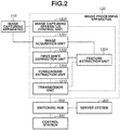
- the image processing apparatus 120 includes an image acquisition unit 1201, a first shift correction unit 1202, a foreground extraction unit 1203, a feature extraction unit 1204, a transmission unit 1210, and an image capturing apparatus control unit 1220.
- the transmission unit 1210 is connected to the switching hub 500 and communicates with external apparatuses, such as the control station 300 and the server system 200, via the switching hub 500.
- the image capturing apparatus control unit 1220 acquires the information via the transmission unit 1210 and controls the image capturing apparatus 110 based on the acquired information.
- the image capturing apparatus 110 captures an image of the image capturing region 1 under control by the image capturing apparatus control unit 1220 and transmits the captured image to the image acquisition unit 1201.
- the image capturing apparatus control unit 1220 causes the image capturing apparatus 110 to perform calibration processing based on the instruction from the control station 300 and acquires the image capturing parameter of the image capturing apparatus 110.
- the image capturing apparatus control unit 1220 transmits the acquired image capturing parameter to the transmission unit 1210. In this operation, the image capturing parameter with an image capturing apparatus identification (image capturing apparatus ID) associated is transmitted.
- the image capturing apparatus ID By the image capturing apparatus ID, the image capturing apparatus 110 that corresponds to the image capturing parameter among the plurality of image capturing apparatuses 110 is identified.
- the image acquisition unit 1201 acquires the captured image transmitted from the image capturing apparatus 110 and transmits the acquired image to the first shift correction unit 1202 and the feature extraction unit 1204.
- the first shift correction unit 1202, the foreground extraction unit 1203, and the feature extraction unit 1204 perform predetermined image processing on the captured image acquired by the image acquisition unit 1201 to acquire image data based on the captured image. Details of the image processing performed by each processing unit will be described below.
- the feature extraction unit 1204 extracts one or more feature points from the captured image transmitted from the image acquisition unit 1201. For example, in a case where an image of a soccer field is captured, an intersection point of a field line or an end point of the field are extracted as a feature point.
- a feature point to be extracted is not limited to those described above. For example, something in the form of a line, such as a field line, can be extracted, or a region having an area can be extracted.
- a feature point can be a patch of a predetermined magnitude (e.g., 3 ⁇ 3 pixels).
- the feature extraction unit 1204 extracts a local feature, such as a point, line, or region having a predetermined feature. While, in the present exemplary embodiment, the example in which a feature point is extracted as a local feature is described, the present exemplary embodiment is also applicable to a case where a local feature, such as a line or region, is extracted.
- the feature extraction unit 1204 transmits information indicating the position of each extracted feature point (hereinafter, the information will be referred to as "feature point position information") and feature information including information indicating the feature of the feature point to the first shift correction unit 1202.
- the feature point position information indicates, for example, two-dimensional coordinates of the feature point on the image. In a case where a region and a patch that have a predetermined feature are extracted, for example, two-dimensional coordinates of a representative point of the region and the patch are transmitted as the position information.
- the feature information contains information based on pixels corresponding to the feature point on the captured image and pixels neighboring the pixels.
- the feature extraction unit 1204 also extracts a plurality of feature points from the image data transmitted from the first shift correction unit 1202 that will be described below.
- the extracted feature points are used in image processing performed by the front end server 210 that will be described below.
- Information to be acquired and an extraction method are similar to those in the method described above, except that a feature point to be extracted in this operation can be a feature point based on an object that moves (changes in position) in the image capturing region 1.
- the feature extraction unit 1204 transmits feature point position information about each extracted feature point and feature information about the feature point to the transmission unit 1210.
- the first shift correction unit 1202 performs correction processing (hereinafter, "first correction processing") to correct the captured image transmitted from the image acquisition unit 1201.
- first correction processing correction processing
- the image capturing apparatus 110 may be shaken by wind or an impact on the installation site, or the lens in the image capturing apparatus 110 may be changed in position or characteristics due to a temperature change.
- a change in the state of the image capturing apparatus 110 as described above may cause a shift between captured images acquired by the plurality of times of image capturing.
- Examples of a shift caused by a change in the state of the image capturing apparatus 110 include a shift in image capturing position that is caused by a change in position of the image capturing apparatus 110, a shift in image capturing direction that is caused by a change in orientation of the image capturing apparatus 110, and a zoom shift that is an enlargement/reduction during image capturing due to a change in position or characteristics of the lens.
- the first shift correction unit 1202 performs processing to correct the shifts based on the plurality of captured images acquired by performing image capturing at a plurality of different time points.
- the first correction processing performed by the first shift correction unit 1202 will be described below.
- the first shift correction unit 1202 acquires a captured image acquired by image capturing at a predetermined time point from the image acquisition unit 1201. In this operation, the captured image is also transmitted to the feature extraction unit 1204.
- the first shift correction unit 1202 performs the first correction processing on the captured image acquired from the image acquisition unit 1201 based on the feature point position information and the feature information that are transmitted from the feature extraction unit 1204. In this operation, the first shift correction unit 1202 holds in advance another captured image (hereinafter, referred to as "reference captured image") acquired by image capturing at a time point different from the predetermined time point and feature point position information and feature information about a feature point on the reference captured image. The first shift correction unit 1202 searches the reference captured image for a feature point corresponding to a feature point on the captured image acquired from the image acquisition unit 1201.
- reference captured image hereinafter, referred to as "reference captured image”
- the corresponding feature point is identified by, for example, scanning the captured image and searching for a feature point having the closest feature to the feature indicated by the feature information about the feature point on the reference captured image. Further, the first shift correction unit 1202 can estimate a predetermined region containing the corresponding feature point on the captured image based on the feature point position information about the feature point on the reference captured image and search the estimated region for the feature point without scanning the entire captured image.
- the first shift correction unit 1202 determines a shift amount indicating the magnitude of a shift based on a shift of coordinates on the captured image between the feature point on the captured image and the feature point on the reference captured image that corresponds to the feature point on the captured image.
- the shift amount is represented by a vector indicating a direction in which the feature point is shifted between the captured image and the reference captured image.
- a method of representing the shift amount is not limited to that described above, and the shift amount can be represented simply by a numerical value. In a case where a plurality of feature points is extracted by the feature extraction unit 1204, a shift amount is determined for each of the plurality of feature points.
- the first shift correction unit 1202 determines a correction amount for correcting the captured image acquired from the image acquisition unit 1201 based on the determined shift amount and performs the first correction processing based on the correction amount. For example, in a case of a shift in image capturing position, the first correction processing is performed to translate the captured image to reduce the shift amount. In a case of a shift in image capturing direction, the captured image is rotated in at least one of pan, tilt, and roll directions with respect to the image capturing apparatus 110 to reduce the shift amount. In a case of a zoom shift, the captured image is enlarged/reduced to reduce the shift amount.
- At least one of an amount of translating the captured image, an amount of rotating the captured image, and an amount of enlarging/reducing the captured image is determined as a correction amount.
- the difference between each shift amount and the correction amount is calculated, and a correction amount optimized to minimize the sum of the absolute values of the differences is determined.
- the first shift correction unit 1202 performs the first correction processing on the captured image based on the determined correction amount and modifies the captured image. As a result of the processing, image data generated by modifying the captured image is acquired.
- the shift amount determination is performed using the reference captured image held in advance
- a specific captured image held in advance does not have to be used.
- the image acquisition unit 1201 acquires moving image frames based on an image capturing frame rate.
- a moving image frame which is a predetermined number of frames before (e.g., one frame before) can be selected as a reference captured image.
- the first shift correction unit 1202 calculates a correction amount to minimize the sum of the absolute values of differences between each shift amount of a plurality of feature points and the correction amount in the order of an amount of translation, an amount of rotation, and an amount of enlargement/reduction.
- the first shift correction unit 1202 performs the first correction processing in the order of translation, rotation, and enlargement/reduction based on the calculated correction amount. With this method, even in a case where a plurality of types of shifts occurs, the first shift correction unit 1202 can still perform correction to reduce the shift amounts.
- the order of the correction amount calculation and the first correction processing can be any order. Only the processing that is desired among the translation, rotation, and enlargement/reduction can be performed.
- the first shift correction unit 1202 acquires reliability information about image data acquired by the first correction processing.
- the reliability information indicates the reliability of the first correction processing.
- the reliability information in the present exemplary embodiment refers to information that indicates the accuracy of the first correction processing performed by the first shift correction unit 1202.
- the reliability information is acquired as described below. For example, in a case where modification is to be performed to translate the captured image, the first shift correction unit 1202 performs optimization calculation to determine a movement amount and direction of the translation to minimize the shift amount of the entire image. A shift amount of each feature point is calculated using the captured image corrected based on the movement amount and direction of the translation that are determined by the calculation and the captured image before the correction.
- the calculated shift amount corresponds to an error of the first correction processing, so that the accuracy of the first correction processing is higher in a case where the shift amount is small than in a case where the shift amount is great.
- the first shift correction unit 1202 acquires the value of the shift amount as the reliability of the first correction processing.
- the first shift correction unit 1202 transmits the image data acquired by performing the first correction processing to the foreground extraction unit 1203 and the feature extraction unit 1204 and transmits the reliability information about the first correction processing to the transmission unit 1210.
- the reliability information can be information that the smaller the calculated shift amount, the higher the accuracy of the first correction processing, or the reliability information can be information indicating the accuracy level in stages based on the magnitude of a shift amount.
- the foreground extraction unit 1203 generates a foreground image that is image data acquired by extracting a foreground region from the image data transmitted from the first shift correction unit 1202.
- the term "foreground image” refers to an image acquired by extracting an object region (foreground region) from a captured image acquired by image capturing by the image capturing apparatus 110.
- An object that is extracted as a foreground region refers to a moving object that moves (may change in its absolute position or shape) in a case where image capturing is performed over time from the same direction.
- Examples of an object are a person, such as a player or a referee in a field where a game is held, a ball in a ball game, and a singer, a player, a performer, or a host in a concert or an entertainment.
- An example of a method of extracting a foreground region is a method in which an image (background image) corresponding to a region other than a foreground region is generated in advance and a difference between the background image and a captured image is calculated to extract the foreground region.
- a method that can be used in a case of a moving image are a method of extracting a foreground region by calculating a difference between moving image frames and a method of extracting a foreground region using machine learning such as convolutional neural network (CNN).
- CNN convolutional neural network
- the foreground extraction unit 1203 transmits the foreground image based on the extracted foreground region as image data to the transmission unit 1210.
- the transmission unit 1210 transmits the image capturing parameter transmitted from the image capturing apparatus control unit 1220 to the server system 200.
- the transmission unit 1210 also transmits the reliability information about the first correction processing and the image data that is transmitted from the foreground extraction unit 1203 and contains the foreground image to the server system 200.
- the transmission unit 1210 also transmits the information containing the feature point position information and the feature information about each feature point that are transmitted from the feature extraction unit 1204 to the server system 200.
- the transmission unit 1210 makes an association between the image capturing parameter, the image data, the reliability information, and the feature point information and performs transmission.
- the image capturing apparatus ID similar to the image capturing parameter, the reliability information, and the feature point information are added to the image data as metadata of the image data, and then the image data is transmitted.
- a functional configuration of the image processing apparatus 120 is described above.
- An advantage of performing the first correction processing by the first shift correction unit 1202 in the image processing apparatus 120 is that the accuracy of image processing in the foreground extraction unit 1203 and the front end server 210 described below increases. For example, if a captured image affected by a shift such as a shift in image capturing position, a shift in image capturing direction, and a zoom shift is used when the foreground extraction unit 1203 calculates a difference between a background image and the captured image to extract a foreground region, the difference may not be calculated accurately. This may result in an issue that a foreground image is not extracted as appropriate.
- the front end server 210 includes an acquisition unit 2110, a determination unit 2120, a second shift correction unit 2130, and a model generation unit 2140.
- the acquisition unit 2110 acquires information, transmitted from the image processing apparatus 120 of the image capturing system 100 via the switching hub 500, such as the image capturing parameter, the image data, the reliability information, and the feature point information. While only one image capturing system 100 is illustrated in Fig. 3 , image data, reliability information, and feature point information are transmitted from each of the plurality of image capturing systems 100 as illustrated in Fig. 1 .
- the acquisition unit 2110 transmits the image capturing parameter to the second shift correction unit 2130 and transmits the plurality of pieces of image data and the feature point information that are acquired to the determination unit 2120.
- the determination unit 2120 determines target image data as a target of second correction processing that is performed by the second shift correction unit 2130, which will be described below, and reference image data as a reference, based on the reliability information transmitted from the acquisition unit 2110.
- image data having the associated reliability information higher than a predetermined threshold value among the plurality of pieces of image data transmitted from the acquisition unit 2110 is determined as reference image data.
- a method of determining reference image data is not limited to the above-described method and, for example, a predetermined number of pieces of reference image data can be determined in decreasing order of reliability.
- image data based on the image capturing performed by the plurality of image capturing apparatuses 110 on an image capturing range that covers the entire image capturing region 1 among the image data with a higher reliability than the predetermined threshold value can be selected as reference image data.
- Image data having the associated reliability information lower than the predetermined threshold value is determined as target image data from among the plurality of pieces of image data transmitted from the acquisition unit 2110.
- a method of determining target image data is not limited to the above-described method and, for example, a predetermined number of pieces of target image data can be determined in increasing order of reliability. Further, for example, all the pieces of image data that are not selected as reference image data among the plurality of pieces of image data can be selected as target image data. As described above, in the present exemplary embodiment, image data having a higher reliability than the reliability of target image data is selected as reference image data.
- the number of image data selected as reference image data can be one or more than one.
- the second shift correction unit 2130 described below associates a feature point on the reference image data with a feature point on the target image data and corrects the target image data based on the associated feature points.
- the target image data may not be corrected as appropriate by the second shift correction unit 2130.
- the plurality of pieces of reference image data that covers the entire image capturing region 1 is selected to produce an advantage that the associating with the feature point on the target image data is performed as appropriate.
- Image data based on the image capturing by the image capturing apparatus 110 adjacent to the image capturing apparatus 110 corresponding to the target image data or image data based on the image capturing by the image capturing apparatus 110 to which the same focused region as that of the image capturing apparatus 110 corresponding to the target image data is set can be selected as reference image data.
- the determination unit 2120 transmits the plurality of pieces of image data transmitted from the acquisition unit 2110 and information for notification of the determined reference image data and the determined target image data to the second shift correction unit 2130.
- the second shift correction unit 2130 and the model generation unit 2140 each perform predetermined image processing based on the image data acquired by the acquisition unit 2110. The image processing performed by each processing unit will be described below.
- the second shift correction unit 2130 performs correction processing (hereinafter, referred to as "second correction processing") to correct the target image data based on information about the feature points on the reference image data and the target image data and the image capturing parameter of the image capturing apparatus 110 corresponding to the reference image data.
- second correction processing is a shift that occurs due to a shift in image capturing position, a shift in image capturing direction, and a zoom shift.
- the second shift correction unit 2130 corrects a shift between pieces of image data acquired based on the image capturing by the different image capturing apparatuses 110 at a predetermined time point. Details of the second correction processing will be described below.
- the second shift correction unit 2130 associates feature points based on information about feature points associated with the plurality of pieces of image data acquired by the acquisition unit 2110.
- the term "corresponding feature points" refers to feature points having feature information indicating substantially the same feature.
- the relationship between the image capturing parameters of the image capturing apparatuses 110 should also be taken into consideration in associating the feature points.
- feature points that have substantially the same feature when the plurality of pieces of image data is projected onto the same two-dimensional coordinates based on at least one of the image capturing parameters of the image capturing apparatuses 110 corresponding to the respective pieces of image data are associated.
- feature points can be associated by, for example, projecting a partial region containing the feature point on the target image data onto the two-dimensional coordinates on the reference image data using the image capturing parameter and then searching for the closest feature to the feature point contained in the deformed partial region.
- a partial region containing the feature point on the reference image data can be projected onto the two-dimensional coordinates on the target image data.
- image data or a partial region of image data can be deformed instead of being projected. This method is also applicable to other local features (e.g., line, region, and patch).
- the second shift correction unit 2130 calculates an epipolar line based on, for example, the feature point on the reference image data and the image capturing parameter corresponding to the reference image data and projects the calculated epipolar line onto another piece of image data. This identifies a feature point having a similar feature and having a short distance between the epipolar line and the feature point on the image data. The identified feature point is determined as a feature point corresponding to the feature point on the reference image data to prevent erroneous association.
- the second shift correction unit 2130 performs shift determination by performing the following processing using a three-dimensional position of the feature point.
- the second shift correction unit 2130 calculates three-dimensional coordinates of the feature point on the reference image data and three-dimensional coordinates of the feature point on the target image data that has a feature corresponding to the feature of the feature point on the reference image data, based on the result of the feature point association.
- the three-dimensional coordinates of the feature point in the image capturing region 1 are calculated by projecting the feature point onto a three-dimensional space or by a method using the principle of triangulation, based on the two-dimensional coordinates of the feature point on the image data and the image capturing parameter corresponding to the image data. In this operation, the plurality of pieces of image data and the image capturing parameters corresponding to the respective pieces of image data are used, and therefore the three-dimensional coordinates are calculated with greater accurately.
- the three-dimensional coordinates of the feature point on the reference image data and the three-dimensional coordinates of the feature point on the target image data are associated feature points, unless there is no change in the state of the image capturing apparatus 110 after the calibration, the three-dimensional coordinates are expected to correspond. However, in a case where there is a change in the state of at least one of the image capturing apparatus 110 corresponding to the reference image data and the image capturing apparatus 110 corresponding to the target image data, the three-dimensional coordinates may be shifted.
- the second shift correction unit 2130 modifies the target image data in such a manner that the three-dimensional coordinates of the feature point on the image data (reference image data) having high reliability and the three-dimensional coordinates of the feature point on the image data (target image data) having low reliability correspond to each other.
- the second shift correction unit 2130 determines that there is a shift based on a difference between the calculated three-dimensional coordinates on the reference image data and the three-dimensional coordinates of the feature point on the target image data. In a case where the second shift correction unit 2130 determines that there is a shift, the image capturing parameter after the change in the state of the image capturing apparatus 110 corresponding to the target image data is calculated using the three-dimensional coordinates of the feature point on the reference image data.
- the image capturing parameter after the change in the state of the image capturing apparatus 110 corresponding to the target image data is calculated by solving the P versus NP problem using the two-dimensional coordinates of the feature point on the target image data with the three-dimensional coordinates of the feature point on the reference image data being a reference.
- the second shift correction unit 2130 calculates a homography matrix H, which indicates a change in the image capturing state of the image capturing apparatus 110 corresponding to the target image data, using the calculated image capturing parameter.
- K is a matrix of three rows and three columns that represents a parameter indicating the focal length of the lens and the lens distortion
- R is a matrix of three rows and three columns that represents the orientation of the image capturing apparatus 110
- t is a matrix of three rows and one column that represents the position of the image capturing apparatus 110.
- R and t are parameters acquired during calibration
- R' and t' are parameters estimated after the change in the state of the image capturing apparatus 110.
- the symbol "+" represents a pseudo inverse matrix.
- the target image data is homographically transformed using the homography matrix H approximated based on Formula 1, and thus a shift between the three-dimensional coordinates of the feature point on the target image data after the homographic transformation and the three-dimensional coordinates of the feature point on the reference image data is corrected.
- the homography matrix H is acquired for each piece of target image data, and the target image data is modified.
- the processing in this operation can be performed sequentially on each piece of target image data or can be performed simultaneously.
- the second correction processing performed by the second shift correction unit 2130 is described above.
- the model generation unit 2140 generates shape data indicating the shape of the object in the image capturing region 1 based on the image capturing parameter and the plurality of pieces of image data including the corrected target image data acquired by the second correction processing by the second shift correction unit 2130.
- the model generation unit 2140 in the present exemplary embodiment generates a three-dimensional model representing the three-dimensional shape of the object using a method, for example, a shape-from-silhouette method, which is a publicly-known technique.
- Shape data to be generated is not limited to three-dimensional models. For example, shape data may be generated based on image-based rendering.
- the model generation unit 2140 transmits the generated object shape data as image data to the database 220. Image data containing the transmitted shape data is used in rendering processing by the back end server 230 to generate a virtual point-of-view image.
- the functional configuration of the front end server 210 is described above.
- a shift between the captured images is corrected based on the plurality of captured images that is acquired by the same image capturing apparatus 110 by performing image capturing at a plurality of different time points.
- the processing is performed using the feature point based on the object that does not change in position at the plurality of different time points, and therefore the shift is corrected.
- the front end server 210 performs the second correction processing to correct a shift between the image data based on the corresponding feature points on the plurality of pieces of image data acquired by the image capturing performed at a predetermined time point by the different image capturing apparatuses 110.
- the second correction processing to correct a shift between the image data based on the corresponding feature points on the plurality of pieces of image data acquired by the image capturing performed at a predetermined time point by the different image capturing apparatuses 110.
- the front end server 210 corrects a shift between the image data by the above-described method even in a case where each of the plurality of image capturing apparatuses 110 is affected by a different shake or a different zoom shift occurs in each of the plurality of image capturing apparatuses 110.
- Figs. 4A and 4B are diagrams illustrating a process performed by the image processing apparatus 120 and a process performed by the front end server 210.
- the CPUs of the image processing apparatus 120 and the front end server 210 read a program stored on the ROMs or the auxiliary storage apparatuses and execute the read program to perform the processes illustrated in Figs. 4A and 4B .
- each processing step will be referred to simply as "S".
- the process is started.
- the image capturing apparatus control unit 1220 sets initial settings of the image processing apparatus 120.
- the calibration processing to acquire the image capturing parameter of the image capturing apparatus 110 is performed, and the reference captured image for use in the first correction processing performed by the first shift correction unit 1202 is acquired.
- the acquired image capturing parameter and the acquired reference captured image are stored on an auxiliary storage apparatus of the image processing apparatus 120.
- a timing to acquire the reference captured image is not limited to the timing of the initial setting, and the reference captured image can be acquired during a plurality of times of image capturing by the image capturing apparatus 110 in step S1020.
- step S 1020 the image capturing apparatus control unit 1220 acquires information about an image capturing instruction transmitted from the control station 300 and controls the image capturing apparatus 110 based on the acquired information.
- the image acquisition unit 1201 acquires a captured image acquired by the image capturing performed by the image capturing apparatus 110 under the control by the image capturing apparatus control unit 1220.
- the first shift correction unit 1202 performs the first correction processing to correct the captured image acquired by the image acquisition unit 1201.
- the feature extraction unit 1204 extracts a plurality of feature points from the captured image acquired by the image acquisition unit 1201.
- the feature extraction unit 1204 transmits position information and feature information about each extracted feature point to the first shift correction unit 1202.
- the first shift correction unit 1202 determines a shift amount indicating the magnitude of the shift based on a shift of coordinates on the captured image between the feature points on the captured image acquired from the image acquisition unit 1201 and feature points on the reference captured image that correspond to the feature points on the captured image.
- the first shift correction unit 1202 performs processing as the first correction processing to modify the captured image in such a manner that the captured image is translated or enlarged/reduced based on the determined shift amount, and the first shift correction unit 1202 acquires corrected image data.
- the first shift correction unit 1202 transmits the acquired image data to the foreground extraction unit 1203 and the feature extraction unit 1204.
- the first shift correction unit 1202 acquires reliability information indicating the reliability of the first correction processing. For example, the first shift correction unit 1202 calculates a shift amount of each feature point based on the corrected captured image and the captured image before the correction. The first shift correction unit 1202 acquires the calculated shift amounts as reliability information and transmits the reliability information to the transmission unit 1210.
- the foreground extraction unit 1203 generates a foreground image by extracting a foreground region from the image data transmitted from the first shift correction unit 1202.
- the foreground extraction unit 1203, for example, generates a background image corresponding to a region other than the foreground region in advance and extracts the foreground region by calculating the difference between the background image and the captured image.
- the foreground extraction unit 1203 transmits the foreground image based on the extracted foreground region as image data to the transmission unit 1210.
- step S1060 the feature extraction unit 1204 extracts a plurality of feature points for use in the second correction processing from the image data acquired from the first shift correction unit 1202.
- a method similar to that in step S1030 is used to extract the feature points.
- the feature points extracted in this operation can include a feature point based on an object that changes in position at different time points.
- the feature extraction unit 1204 transmits position information and feature information about each feature point to the transmission unit 1210.
- step S1070 the transmission unit 1210 transmits the image data containing the foreground image transmitted from the foreground extraction unit 1203 to the server system 200.
- the transmission unit 1210 also transmits the image capturing parameter of the image capturing apparatus 110, the reliability information about the first correction processing, and the feature point information about the image data to the server system 200. Then, the series of processing from the initial setting to the image data transmission by the image processing apparatus 120 is ended. In a case where the image capturing apparatus 110 continuously performs image capturing, steps S1020 to S1070 can be repeated.
- step S1110 the acquisition unit 2110 acquires the image capturing parameter transmitted from the image processing apparatus 120 and initializes the front end server 210 by setting a setting in such a manner that the acquired image capturing parameter is used in step S1120 and thereafter.
- the image capturing parameter is acquired from the image processing apparatus 120 in step S1110 in the present exemplary embodiment, the present exemplary embodiment is not limited to those described above.
- the image capturing parameter can be stored in advance on an auxiliary storage apparatus before the process illustrated in Fig. 4B , and the stored image capturing parameter can be read.
- step S1120 the acquisition unit 2110 acquires the image data transmitted from the image processing apparatus 120. Further, the acquisition unit 2110 acquires the reliability information and the feature point information.
- step S1130 the determination unit 2120 determines target image data as a target of the second correction processing performed by the second shift correction unit 2130, which will be described below, and reference image data as a reference, based on the reliability information transmitted from the acquisition unit 2110. For example, the determination unit 2120 determines image data having the associated reliability information higher than the predetermined threshold value as reference image data and determines image data having the associated reliability information lower than the predetermined threshold value as target image data, from among the plurality of pieces of image data.
- step S1140 the second shift correction unit 2130 performs the second correction processing to correct the target image data based on the information about the feature points on the reference image data and the target image data and the image capturing parameter of the image capturing apparatus 110 corresponding to the reference image data. Details of the processing in step S1140 will be described below with reference to Fig. 5 .
- step S1141 the second shift correction unit 2130 associates the feature points based on the feature point information associated with the plurality of pieces of image data acquired by the acquisition unit 2110. For example, the second shift correction unit 2130 searches for the feature points having substantially the same feature based on the feature information to associate the feature points.
- the second shift correction unit 2130 calculates three-dimensional coordinates of the feature points on the reference image data and three-dimensional coordinates of the feature points on the target image data that correspond to the feature points on the reference image data, based on the result of associating the feature points.
- the three-dimensional coordinates of the feature points in the image capturing region 1 are calculated by projecting the feature points onto a three-dimensional space or by a method using the principle of triangulation, based on the two-dimensional coordinates of the feature points on the image data and the image capturing parameter corresponding to the image data.
- step S1143 the second shift correction unit 2130 determines that there is a shift based on a difference between the calculated three-dimensional coordinates on the reference image data and the three-dimensional coordinates of the feature points on the target image data.
- step S1144 in a case where the second shift correction unit 2130 determines that there is a shift, the image capturing parameter after the change in the state of the image capturing apparatus 110 corresponding to the target image data is calculated by solving the P versus NP problem using the three-dimensional coordinates of the feature points on the reference image data.
- the second shift correction unit 2130 calculates the homography matrix H, which indicates a change in the image capturing state of the image capturing apparatus 110 corresponding to the target image data, using the calculated image capturing parameter.
- step S1145 the second shift correction unit 2130 homographically transforms the target image data using the calculated homography matrix H to acquire image data with the shift corrected. Further, the second shift correction unit 2130 transmits the acquired image data to the model generation unit 2140. In a case where there is a plurality of pieces of target image data, steps S1143 to S1145 are repeated until all the pieces of target image data are processed.
- the model generation unit 2140 generates shape data indicating the shape of the object in the image capturing region 1 based on the image capturing parameter and the plurality of pieces of image data including the corrected target image data. For example, the model generation unit 2140 generates a three-dimensional model of the object based on the foreground image using a method, such as a shape-from-silhouette method, which is a publicly-known technique. The model generation unit 2140 transmits the generated shape data as image data to the database 220. Then, the process by the front end server 210 is ended.
- the front end server 210 can perform correction to change the image capturing parameter of the image capturing apparatus 110 corresponding to the target image data to the image capturing parameter after the change in the state of the image capturing apparatus 110 that is estimated by the second shift correction unit 2130 without calculating the homography matrix H.
- the model generation unit 2140 generates shape data based on the changed image capturing parameter and the image data (foreground image).
- the method of correcting the image capturing parameter is effective in a case where, for example, the position and orientation of the image capturing apparatus 110 are changed by shaking the image capturing apparatus 110 and the changed state continues.
- the second correction processing after the state is changed is reduced by correcting the image capturing parameter to the image capturing parameter corresponding to the image capturing apparatus 110 after the state is changed.
- both the target image data and the image capturing parameter of the image capturing apparatus 110 that correspond to the target image data can be corrected.
- a shift between the positions of the feature points on the reference image data and the positions of the feature points on the target image data is divided into a plurality of direction components, and one of the target image data and the image capturing parameter of the image capturing apparatus 110 that corresponds to the target image data is corrected for each component.
- the reliability information is acquired based on the accuracy of the first correction processing is described above, this is not a limiting case.
- the correction processing is performed based on the associated feature points, so that image data that contains many feature points is determined as reference image data.
- the accuracy of the correction in the second correction processing may increase.
- the reliability information can be determined based on the number of extracted feature points.
- Reliability information can also be determined based on the focal length of the lens of the image capturing apparatus 110 since, as the angle of view of the image capturing apparatus 110 is increased, captured images are expected to contain more feature points.
- Reliability information can also be determined based on the position of the image capturing apparatus 110, since captured images acquired by the image capturing apparatus 110 that is disposed at a position where the image capturing apparatus 110 is less likely to be affected by shakes are less likely to be shifted.
- the front end server 210 can select reference image data based on the focal length and position of the image capturing apparatus 110.
- the image capturing apparatus 110 that is to be used to acquire reference image data can also be designated by user input.
- the second shift correction unit 2130 in the first exemplary embodiment determines a difference between the three-dimensional coordinates on the reference image data and the three-dimensional coordinates of the feature points on the target image data as a shift
- the following method can also be used to determine a shift.
- the second shift correction unit 2130 projects the three-dimensional coordinates of the feature points on the reference image data onto the target image data using the image capturing parameter of the image capturing apparatus 110 that corresponds to the target image data, and the second shift correction unit 2130 performs shift determination based on a difference between the two-dimensional coordinates of the feature points.
- the second shift correction unit 2130 projects the three-dimensional coordinates of the feature points on the target image data onto the reference image data using the image capturing parameter of the image capturing apparatus 110 that corresponds to the reference image data, and the second shift correction unit 2130 performs shift determination based on a difference between the two-dimensional coordinates of the feature points.
- various methods can be used to determine a shift.
- the second shift correction unit 2130 can also modify the target image data in such a manner that the distance between each feature point and the corresponding epipolar line is minimized after projecting the epipolar line based on the feature points on the reference image data onto the target image data. Specifically, the second shift correction unit 2130 can also perform shift correction by correcting a shift between the positions of the feature points in a case where the feature points on the reference image data are projected onto the target image data using the image capturing parameter and the positions of the corresponding feature points on the target image.
- the second shift correction unit 2130 can also perform shift correction by correcting a shift between the positions of the feature points in a case where the feature points on the target image data are projected onto the reference image data using the image capturing parameter and the positions of the corresponding feature points on the reference image.
- the first shift correction unit 1202 and the second shift correction unit 2130 can determine a correction amount of image data to reduce shifts caused by the shakes, based on the period and magnitude of the shakes. As described above, once a correction amount is determined, image data is corrected to reduce shifts with respect to the same shake.
- the first shift correction unit 1202 and the second shift correction unit 2130 can include a function of identifying the period and magnitude of shakes based on shifts.
- the first shift correction unit 1202 can be included in the front end server 210.
- the front end server 210 stores the reference captured image in advance on an auxiliary storage apparatus or the like and acquires a captured image from the image processing apparatus 120 to perform the first correction processing.
- at least one of the feature extraction unit 1204 and the foreground extraction unit 1203 can be included in the front end server 210.
- the present exemplary embodiment is not limited to those described above.
- the image capturing apparatus 110 can be provided with a shake detection sensor, and only in a case where a shake greater than a predetermined threshold value is detected, at least one of the first correction processing and the second correction processing can be performed.
- Each of the first correction processing and the second correction processing can be turned on/off based on a user operation.
- the second correction processing can be skipped in a case where it is determined that there is not a shift.
- the shift determination in step S1143 it can be determined that there is a shift in a case where the magnitude of the shift is greater than or equal to a predetermined threshold value.
- the front end server 210 of the information processing system 10 corrects a shift between image data that is caused by a change in the state of the image capturing apparatus 110, and therefore an effect of the change in the state of the image capturing apparatus 110 is reduced.
- the front end server 210 corrects at least one of the target image data and the image capturing parameter of the image capturing apparatus 110 that corresponds to the target image data.
- an image processing system including an image capturing apparatus (hereinafter, also referred to as "image capturing apparatus for correction") for acquiring a captured image for use in correction processing in addition to the image capturing apparatus 110 will be described below.
- Fig. 6 is a diagram illustrating a configuration of an image processing system 20.
- the image processing system 20 includes the image capturing apparatus 110, an image capturing apparatus 111 for correction, and an image processing apparatus 121.
- the image processing apparatus 121 includes the image acquisition unit 1201, the first shift correction unit 1202, the feature extraction unit 1204, and the second shift correction unit 2130. While the image acquisition unit 1201 and the feature extraction unit 1204 each include two processing units, one for processing captured images from the image capturing apparatus 111 and the other for processing captured images from the image capturing apparatus 110 in Fig. 6 for convenience of description, the two processing units can be a single processing unit.
- the processing units that have similar functions to those of the information processing system 10 in the first exemplary embodiment are given the same reference numerals.
- a hardware configuration of the image processing apparatus 121 is similar to that of the image processing apparatus 120 in the first exemplary embodiment, so that redundant descriptions thereof are omitted.
- the image capturing apparatus 111 for correction is set to have a wider angle of view than the angle of view of the image capturing apparatus 110 to capture sufficient feature points for use in the second correction processing in captured images.
- the image capturing apparatus 111 for correction transmits an acquired captured image to the image processing apparatus 120.
- the image capturing apparatus control unit 1220 controls the image capturing apparatus 111 for correction and the image capturing apparatus 110 based on an instruction from the control station 300 or user input. In this operation, the image capturing apparatus 111 for correction and the image capturing apparatus 110 perform image capturing at synchronized image capturing time points.
- the image acquisition unit 1201a acquires the captured image from the image capturing apparatus 111 for correction and transmits the captured image to the first shift correction unit 1202.
- the image acquisition unit 1201b acquires a captured image from the image capturing apparatus 110 and supplies the captured image to the feature extraction unit 1204b.
- the first shift correction unit 1202 performs the first correction processing based on the captured image transmitted from the image acquisition unit 1201a and the reference captured image and acquires corrected image data.
- the first correction processing method and the reference captured image acquisition method are similar to those in the first exemplary embodiment.
- the feature extraction unit 1204a extracts a feature point from the image data acquired by the first shift correction unit 1202 and transmits feature point information to the second shift correction unit 2130.
- the feature extraction unit 1204b extracts a feature point from the captured image transmitted from the image acquisition unit 1201b and transmits feature point information to the second shift correction unit 2130.
- the feature point extraction method is similar to that in the first exemplary embodiment.
- the second shift correction unit 2130 associates the feature points based on the feature point information transmitted from the feature extraction unit 1204a and the feature extraction unit 1204b and determines a shift amount.
- the second shift correction unit 2130 performs correction by modifying the captured image acquired from the image capturing apparatus 110, based on the determined shift amount to reduce the shift amount.
- the second shift correction unit 2130 performs the second correction processing using image data based on the image capturing by the image capturing apparatus 111 for correction as reference image data and the captured image based on the image capturing by the image capturing apparatus 110 as target image data.
- the second correction processing method is similar to that in the first exemplary embodiment.
- the second shift correction unit 2130 transmits image data acquired by performing the second correction processing to another information processing apparatus 21.
- the information processing apparatus 21 is, for example, the front end server 210.
- the first shift correction unit 1202 for the image capturing apparatus 110 can also be prepared.
- the feature points are associated using a captured image acquired from the image capturing apparatus 111 for correction that captures images of a wider range. While, in the present exemplary embodiment, the image capturing apparatus 111 for correction is used only to correct captured images acquired from the image capturing apparatus 110, captured images acquired from the image capturing apparatus 111 for correction can be used in generating a foreground image or shape data.
- a single image capturing apparatus 111 for correction can transmit captured images to each image processing apparatus 120, or two or more image capturing apparatuses 111 for correction can each transmit captured images to a predetermined image processing apparatus 120. As described above, any desired number of image capturing apparatuses 111 for correction can be included.
- a plurality of captured images can be used in generating image content other than a virtual point-of-view image.
- a panoramic image is to be generated as image content
- use of the target image data and/or the image capturing parameter corrected by the above-described method reduces position shifts in combining image data.
- image content for analyzing an orientation and movement of a subject e.g., athlete
- image content for use in making judgements in sports are to be generated
- Use of the target image data and/or the image capturing parameter corrected by the above-described method realizes high accuracy in analysis and judgement.
- Embodiment(s) of the present invention can also be realized by a computer of a system or apparatus that reads out and executes computer executable instructions (e.g., one or more programs) recorded on a storage medium (which may also be referred to more fully as a 'non-transitory computer-readable storage medium') to perform the functions of one or more of the above-described embodiment(s) and/or that includes one or more circuits (e.g., application specific integrated circuit (ASIC)) for performing the functions of one or more of the above-described embodiment(s), and by a method performed by the computer of the system or apparatus by, for example, reading out and executing the computer executable instructions from the storage medium to perform the functions of one or more of the above-described embodiment(s) and/or controlling the one or more circuits to perform the functions of one or more of the above-described embodiment(s).
- computer executable instructions e.g., one or more programs
- a storage medium which may also be referred to more fully as
- the computer may comprise one or more processors (e.g., central processing unit (CPU), micro processing unit (MPU)) and may include a network of separate computers or separate processors to read out and execute the computer executable instructions.
- the computer executable instructions may be provided to the computer, for example, from a network or the storage medium.
- the storage medium may include, for example, one or more of a hard disk, a random-access memory (RAM), a read only memory (ROM), a storage of distributed computing systems, an optical disk (such as a compact disc (CD), digital versatile disc (DVD), or Blu-ray Disc (BD)TM), a flash memory device, a memory card, and the like.
Landscapes
- Engineering & Computer Science (AREA)
- General Physics & Mathematics (AREA)
- Theoretical Computer Science (AREA)
- Physics & Mathematics (AREA)
- Signal Processing (AREA)
- Multimedia (AREA)
- Computer Vision & Pattern Recognition (AREA)
- General Engineering & Computer Science (AREA)
- Software Systems (AREA)
- Computer Hardware Design (AREA)
- Computer Graphics (AREA)
- Architecture (AREA)
- Studio Devices (AREA)
- Image Processing (AREA)
- Processing Or Creating Images (AREA)
- Image Generation (AREA)
Abstract
Description
- The present disclosure relates to information processing apparatuses, information processing methods, and a program.
- In recent years, techniques for generating various types of image content using a plurality of captured images acquired by a plurality of image capturing apparatuses have drawn attention. Examples of image content include virtual point-of-view images and panoramic images. Further, techniques for generating image content based on a plurality of captured images are expected to be used in analyzing orientations and movements of subjects (e.g., athletes) and in making judgements in sports.
- For example, in a case where a virtual point-of-view image is to be generated, a plurality of image capturing apparatuses is arranged around an image capturing region and captures images, and an image (virtual point-of-view image) from a designated point of view (virtual point of view) is generated based on the plurality of captured images acquired from the image capturing apparatuses. In this operation, subject shape data for displaying the virtual point-of-view image is generated using the plurality of captured images and information indicating a state of the plurality of image capturing apparatuses, such as positions, orientations, and focal lengths of the plurality of image capturing apparatuses that are preset. However, the image capturing apparatuses may be shaken or lens positions and characteristics may be changed while image capturing is performed, and this may cause a change in the positions, orientations, and focal lengths of the image capturing apparatuses. In other words, the state of the image capturing apparatuses changes. In such a case, if the change in the state of the image capturing apparatuses is not taken into account in generating shape data, the accuracy of generated shape data decreases and, consequently, the quality (image quality) of the virtual point-of-view image decreases. Thus, a change in the state of the image capturing apparatuses may affect the quality of generated image content.
- Japanese Patent Laid-Open No.
2017-69920 2017-69920 - According to the technique discussed in Japanese Patent Laid-Open No.
2017-69920 - According to one aspect of the present invention, there is provided an information processing apparatus as specified in any one of claims 1 to 15.
- According to one aspect of the present invention, there is provided an information processing method as specified in claim 16.
- According to one aspect of the present invention, there is provided a computer program as specified in claim 17.
- Further features of the present invention will become apparent from the following description of exemplary embodiments with reference to the attached drawings.
-
-
Fig. 1 is a diagram illustrating a configuration of an information processing system. -
Fig. 2 is a diagram illustrating a functional configuration of an image processing apparatus. -
Fig. 3 is a diagram illustrating a functional configuration of a front end server. -
Figs. 4A and 4B are flowcharts illustrating processes that are executed by the image processing apparatus and the front end server. -
Fig. 5 is a flowchart illustrating details of a second correction process. -
Fig. 6 is a diagram illustrating a configuration of an information processing system including an image capturing apparatus for correction. -
Fig. 7 is a diagram illustrating a hardware configuration of a front end server of the information processing system. -
Fig. 8 is a diagram illustrating an example of an arrangement of a plurality of image capturing apparatuses. - Various exemplary embodiments of the present invention will be described below with reference to the drawings. It should be noted that each component described in the exemplary embodiments below merely illustrates an example of an exemplary embodiment of the present invention and that the present disclosure is not limited to the illustrated examples.
- In the present exemplary embodiment, an information processing system that performs processing to generate virtual point-of-view images will be described below as an example of a system including a plurality of image capturing apparatuses. The term "virtual point-of-view image" refers to an image of a view captured from a designated virtual point of view based on a plurality of images captured by the plurality of image capturing apparatuses and the designated point of view (virtual point of view). Further, a virtual point-of-view image in the present exemplary embodiment is also referred to as a free point-of-view image and is not limited to an image that corresponds to a point of view designated freely (as desired) by a user and, for example, an image that corresponds to a point of view selected from a plurality of candidates by a user is also an example of a virtual point-of-view image. A virtual point-of-view image in the present exemplary embodiment can be either one of a still image and a moving image. Image data that is used in the information processing system can be either one of a still image and a moving image. In other words, the information processing system according to the present exemplary embodiment can process both still images and moving images.
- A hardware configuration of each apparatus included in the information processing system according to the present exemplary embodiment will be described below with reference to
Fig. 7 . Afront end server 210 inFig. 7 includes a central processing unit (CPU) 701, a read-only memory (ROM) 702, a random access memory (RAM) 703, anauxiliary storage apparatus 704, adisplay unit 705, anoperation unit 706, a communication interface (communication I/F) 707, and abus 708. An image processing apparatus, a control station, and a back end server that will be described below also have a hardware configuration including at least one of a CPU, a ROM, a RAM, an auxiliary storage apparatus, a display unit, an operation unit, a communication I/F, and a bus. As an example, a feature of each component of thefront end server 210 will be described below. - The
CPU 701 controls the entirefront end server 210 using a computer program and data stored on theROM 702 and/or theRAM 703 to realize a function of a processing unit included in thefront end server 210. Thefront end server 210 can include a single piece or plurality of pieces of dedicated hardware different from theCPU 701, and the dedicated hardware can execute at least part of the processing of theCPU 701. Examples of dedicated hardware include an application-specific integrated circuit (ASIC), a field-programmable gate array (FPGA), and a digital signal processor (DSP). TheROM 702 stores programs that do not need changes. TheRAM 703 temporarily stores programs and data supplied from theauxiliary storage apparatus 704 and data supplied externally via the communication I/F 707. Theauxiliary storage apparatus 704 includes, for example, a hard disk drive and stores various types of data, such as image data and audio data. - The
display unit 705 includes, for example, a liquid crystal display and a light emitting diode (LED) and displays a graphical user interface (GUI) that is used by a user to operate thefront end server 210. Theoperation unit 706 includes, for example, a keyboard, a mouse, a joystick, and a touch panel and inputs various instructions to theCPU 701 based on received user operations. TheCPU 701 operates as a display control unit that controls thedisplay unit 705 and as an operation control unit that controls theoperation unit 706. - The communication I/
F 707 is used to communicate with an external apparatus provided outside thefront end server 210. For example, in a case where thefront end server 210 is connected to an external apparatus via wire, a cable for communication is connected to the communication I/F 707. In a case where thefront end server 210 includes a function of wirelessly communicating with an external apparatus, the communication I/F 707 includes an antenna. Thebus 708 connects the components of thefront end server 210 together and transmits information. - While the
display unit 705 and theoperation unit 706 are in thefront end server 210 inFig. 7 , this is not a limiting configuration. At least one of thedisplay unit 705 and theoperation unit 706 can be a separate apparatus disposed outside thefront end server 210. Further, one or both of thedisplay unit 705 and theoperation unit 706 can be not included. This also applies to an image processing apparatus, a control station, and a back end server that will be described below. In below-described exemplary embodiments, a display apparatus and a virtual point-of-view operation user interface (virtual point-of-view operation UI) described below respectively correspond to thedisplay unit 705 and theoperation unit 706 that are externally connected to thefront end server 210. - Next, a configuration of the information processing system according to the present exemplary embodiment will be described below.
Fig. 1 illustrates a configuration of aninformation processing system 10. Theinformation processing system 10 includes a plurality of image capturingsystems 100a to 110n, aserver system 200, acontrol station 300, an input/output system 400, and aswitching hub 500. Each component will be described below. - The
image capturing system 100a includes animage capturing apparatus 110a and animage processing apparatus 120a. Similarly, theimage capturing systems 100b to 100n respectively includeimage capturing apparatuses 110b to 110n andimage processing apparatuses 120b to 120n. Hereinafter, unless otherwise specified, theimage capturing systems 100a to 100n and theimage capturing apparatuses 110a to 110n and theimage processing apparatuses 120a to 120n of theimage capturing systems 100a to 110n will not be discriminated and will be referred to simply as theimage capturing system 100, theimage capturing apparatus 110, and theimage processing apparatus 120. Further, the number ofimage capturing systems 100 is two or more. - The plurality of
image capturing apparatuses 110 receives an image capturing instruction transmitted from thecontrol station 300 via theswitching hub 500 and captures images at synchronized image capturing timings. An example of an arrangement of the plurality ofimage capturing apparatuses 110 will be described below with reference toFig. 8 . As illustrated inFig. 8 , the plurality ofimage capturing apparatuses 110 are arranged to surround an image capturing region 1 and captures images of the image capturing region 1 from different directions. The image capturing region 1 is, for example, a stadium where games of soccer, karate or the like are played, or a stage where concerts and plays are performed. The plurality ofimage capturing apparatuses 110 does not have to be disposed around the entire perimeter of the image capturing region 1, and depending on installation site restrictions, the plurality ofimage capturing apparatuses 110 can be installed only at predetermined positions. The plurality ofimage capturing apparatuses 110 does not have to be fixed to the same base and, for example, eachimage capturing apparatus 110 can be fixed to a different pillar. - The number of
image capturing apparatuses 110 is not limited to the example illustrated inFig. 8 , and in a case where, for example, the image capturing region 1 is a soccer stadium, about thirtyimage capturing apparatuses 110 can be installed around the stadium. Theimage capturing apparatuses 110 of different functions, such as telephoto cameras and wide-angle cameras, can be also installed. The plurality ofimage capturing apparatuses 110 transmits captured images of the image capturing region 1 to the respectiveimage processing apparatuses 120. - The
image processing apparatus 120 acquires captured images from theimage capturing apparatus 110 connected toimage processing apparatus 120 and performs predetermined image processing on the acquired captured images. Details of the image processing performed by theimage processing apparatus 120 will be described below. Theimage processing apparatus 120 transmits image data acquired by performing the image processing to theserver system 200 via theswitching hub 500. - The
server system 200 includes thefront end server 210, adatabase 220, and aback end server 230. Thefront end server 210 performs predetermined image processing to generate a virtual point-of-view video image based on the image data transmitted from theimage capturing system 100. Details of the image processing performed by thefront end server 210 will be described below. Thefront end server 210 performs the predetermined image processing to generate image data, such as shape data representing the shape of a subject (e.g., a person or ball in the image capturing region 1) and texture data representing colors of the shape data. Thefront end server 210 stores the generated image data on thedatabase 220. - The
back end server 230 acquires inputs to a virtual point-of-view operation user interface (virtual point-of-view operation UI) 410 of the input/output system 400. The virtual point-of-view operation UI 410 provides a user interface (UI) for operations of designating a virtual point of view. A user can designate a point-of-view position of a virtual point of view and a line-of-sight direction by operating the virtual point-of-view operation UI 410. The inputs received by the virtual point-of-view operation UI 410 are transmitted as virtual point-of-view information containing a parameter indicating the point-of-view position of the virtual point of view and a parameter indicating the line-of-sight direction from the virtual point of view to theback end server 230. Theback end server 230 acquires the virtual point-of-view information transmitted from the virtual point-of-view operation UI 410 and acquires image data for generating a virtual point-of-view image corresponding to the virtual point-of-view designated based on the acquired virtual point-of-view information from thedatabase 220. Theback end server 230 performs rendering processing using the acquired image data to generate a virtual point-of-view image. The generated virtual point-of-view image is transmitted to adisplay apparatus 420 of the input/output system 400 and displayed. While, in the present exemplary embodiment, the virtual point-of-view information acquired based on the operation of designating the virtual point of view contains the parameter indicating the point-of-view position of the virtual point of view and the parameter indicating the line-of-sight direction from the virtual point of view, information contained in the virtual point-of-view information is not limited to those described above. For example, information about an angle of view of the virtual point of view can be contained. Further, at least one of the point-of-view position of the virtual point of view, the line-of-sight direction from the virtual point of view, and the angle of view of the virtual point of view can be contained in the virtual point-of-view information. - The configuration of the
server system 200 is not limited to the configuration illustrated inFig. 1 . For example, at least two of thefront end server 210, thedatabase 220, and theback end server 230 can be integrated together. Theimage processing apparatus 120 or the input/output system 400 can include at least part of the functions of theserver system 200. - The
control station 300 is connected to theimage capturing system 100 and theserver system 200 via theswitching hub 500. Thecontrol station 300 manages theimage capturing system 100 and theserver system 200 and controls image capturing. Thecontrol station 300 also controls the plurality ofimage capturing apparatuses 110 to perform calibration processing to acquire an image capturing parameter that indicates a state of the plurality ofimage capturing apparatuses 110. As used herein, the term "image capturing parameter" refers to image capturing information including information about a position, an orientation, a focal length of a lens, and a lens distortion. The image capturing parameter does not have to include information about every one of the position, the orientation, the focal length of the lens, and the lens distortion and is to include at least one of the position and the orientation. Information other than those described above can further be contained. - Next, a functional configuration of the
image processing apparatus 120 of theinformation processing system 10 will be described below with reference toFig. 2 . Theimage processing apparatus 120 includes animage acquisition unit 1201, a firstshift correction unit 1202, aforeground extraction unit 1203, afeature extraction unit 1204, atransmission unit 1210, and an image capturingapparatus control unit 1220. Thetransmission unit 1210 is connected to theswitching hub 500 and communicates with external apparatuses, such as thecontrol station 300 and theserver system 200, via theswitching hub 500. - In a case where image capturing instruction information is transmitted from the
control station 300, the image capturingapparatus control unit 1220 acquires the information via thetransmission unit 1210 and controls theimage capturing apparatus 110 based on the acquired information. Theimage capturing apparatus 110 captures an image of the image capturing region 1 under control by the image capturingapparatus control unit 1220 and transmits the captured image to theimage acquisition unit 1201. The image capturingapparatus control unit 1220 causes theimage capturing apparatus 110 to perform calibration processing based on the instruction from thecontrol station 300 and acquires the image capturing parameter of theimage capturing apparatus 110. The image capturingapparatus control unit 1220 transmits the acquired image capturing parameter to thetransmission unit 1210. In this operation, the image capturing parameter with an image capturing apparatus identification (image capturing apparatus ID) associated is transmitted. By the image capturing apparatus ID, theimage capturing apparatus 110 that corresponds to the image capturing parameter among the plurality ofimage capturing apparatuses 110 is identified. Theimage acquisition unit 1201 acquires the captured image transmitted from theimage capturing apparatus 110 and transmits the acquired image to the firstshift correction unit 1202 and thefeature extraction unit 1204. - The first
shift correction unit 1202, theforeground extraction unit 1203, and thefeature extraction unit 1204 perform predetermined image processing on the captured image acquired by theimage acquisition unit 1201 to acquire image data based on the captured image. Details of the image processing performed by each processing unit will be described below. - The
feature extraction unit 1204 extracts one or more feature points from the captured image transmitted from theimage acquisition unit 1201. For example, in a case where an image of a soccer field is captured, an intersection point of a field line or an end point of the field are extracted as a feature point. A feature point to be extracted, however, is not limited to those described above. For example, something in the form of a line, such as a field line, can be extracted, or a region having an area can be extracted. A feature point can be a patch of a predetermined magnitude (e.g., 3 × 3 pixels). Specifically, thefeature extraction unit 1204 extracts a local feature, such as a point, line, or region having a predetermined feature. While, in the present exemplary embodiment, the example in which a feature point is extracted as a local feature is described, the present exemplary embodiment is also applicable to a case where a local feature, such as a line or region, is extracted. - As the feature points extracted by the
feature extraction unit 1204 include a greater number of feature points based on an object that remains unchanged in position at different time points, the accuracy of the processing performed by the firstshift correction unit 1202 that will be described below is expected to increase. Thefeature extraction unit 1204 transmits information indicating the position of each extracted feature point (hereinafter, the information will be referred to as "feature point position information") and feature information including information indicating the feature of the feature point to the firstshift correction unit 1202. The feature point position information indicates, for example, two-dimensional coordinates of the feature point on the image. In a case where a region and a patch that have a predetermined feature are extracted, for example, two-dimensional coordinates of a representative point of the region and the patch are transmitted as the position information. Further, the feature information contains information based on pixels corresponding to the feature point on the captured image and pixels neighboring the pixels. - The
feature extraction unit 1204 also extracts a plurality of feature points from the image data transmitted from the firstshift correction unit 1202 that will be described below. The extracted feature points are used in image processing performed by thefront end server 210 that will be described below. Information to be acquired and an extraction method are similar to those in the method described above, except that a feature point to be extracted in this operation can be a feature point based on an object that moves (changes in position) in the image capturing region 1. Thefeature extraction unit 1204 transmits feature point position information about each extracted feature point and feature information about the feature point to thetransmission unit 1210. - The first
shift correction unit 1202 performs correction processing (hereinafter, "first correction processing") to correct the captured image transmitted from theimage acquisition unit 1201. In a case where theimage capturing apparatus 110 performs image capturing a plurality of times, for example, theimage capturing apparatus 110 may be shaken by wind or an impact on the installation site, or the lens in theimage capturing apparatus 110 may be changed in position or characteristics due to a temperature change. A change in the state of theimage capturing apparatus 110 as described above may cause a shift between captured images acquired by the plurality of times of image capturing. Examples of a shift caused by a change in the state of theimage capturing apparatus 110 include a shift in image capturing position that is caused by a change in position of theimage capturing apparatus 110, a shift in image capturing direction that is caused by a change in orientation of theimage capturing apparatus 110, and a zoom shift that is an enlargement/reduction during image capturing due to a change in position or characteristics of the lens. The firstshift correction unit 1202 performs processing to correct the shifts based on the plurality of captured images acquired by performing image capturing at a plurality of different time points. - The first correction processing performed by the first
shift correction unit 1202 will be described below. The firstshift correction unit 1202 acquires a captured image acquired by image capturing at a predetermined time point from theimage acquisition unit 1201. In this operation, the captured image is also transmitted to thefeature extraction unit 1204. - The first
shift correction unit 1202 performs the first correction processing on the captured image acquired from theimage acquisition unit 1201 based on the feature point position information and the feature information that are transmitted from thefeature extraction unit 1204. In this operation, the firstshift correction unit 1202 holds in advance another captured image (hereinafter, referred to as "reference captured image") acquired by image capturing at a time point different from the predetermined time point and feature point position information and feature information about a feature point on the reference captured image. The firstshift correction unit 1202 searches the reference captured image for a feature point corresponding to a feature point on the captured image acquired from theimage acquisition unit 1201. The corresponding feature point is identified by, for example, scanning the captured image and searching for a feature point having the closest feature to the feature indicated by the feature information about the feature point on the reference captured image. Further, the firstshift correction unit 1202 can estimate a predetermined region containing the corresponding feature point on the captured image based on the feature point position information about the feature point on the reference captured image and search the estimated region for the feature point without scanning the entire captured image. - The first
shift correction unit 1202 determines a shift amount indicating the magnitude of a shift based on a shift of coordinates on the captured image between the feature point on the captured image and the feature point on the reference captured image that corresponds to the feature point on the captured image. The shift amount is represented by a vector indicating a direction in which the feature point is shifted between the captured image and the reference captured image. A method of representing the shift amount is not limited to that described above, and the shift amount can be represented simply by a numerical value. In a case where a plurality of feature points is extracted by thefeature extraction unit 1204, a shift amount is determined for each of the plurality of feature points. The firstshift correction unit 1202 determines a correction amount for correcting the captured image acquired from theimage acquisition unit 1201 based on the determined shift amount and performs the first correction processing based on the correction amount. For example, in a case of a shift in image capturing position, the first correction processing is performed to translate the captured image to reduce the shift amount. In a case of a shift in image capturing direction, the captured image is rotated in at least one of pan, tilt, and roll directions with respect to theimage capturing apparatus 110 to reduce the shift amount. In a case of a zoom shift, the captured image is enlarged/reduced to reduce the shift amount. Thus, at least one of an amount of translating the captured image, an amount of rotating the captured image, and an amount of enlarging/reducing the captured image is determined as a correction amount. In a case where shift amounts of a plurality of feature points are determined, for example, the difference between each shift amount and the correction amount is calculated, and a correction amount optimized to minimize the sum of the absolute values of the differences is determined. The firstshift correction unit 1202 performs the first correction processing on the captured image based on the determined correction amount and modifies the captured image. As a result of the processing, image data generated by modifying the captured image is acquired. - While, in the present exemplary embodiment, the shift amount determination is performed using the reference captured image held in advance, a specific captured image held in advance does not have to be used. For example, in a case where the
image capturing apparatus 110 captures a moving image, theimage acquisition unit 1201 acquires moving image frames based on an image capturing frame rate. In this operation, a moving image frame which is a predetermined number of frames before (e.g., one frame before) can be selected as a reference captured image. - In a case where a plurality of types of shifts, such as a shift in image capturing position, a shift in image capturing direction, and a zoom shift, occurs in combination, a plurality of correction methods corresponding to the shifts is performed in combination to correct the image data. In this operation, the types of the shifts that occur do not necessarily have to be identified. For example, the first
shift correction unit 1202 calculates a correction amount to minimize the sum of the absolute values of differences between each shift amount of a plurality of feature points and the correction amount in the order of an amount of translation, an amount of rotation, and an amount of enlargement/reduction. Further, the firstshift correction unit 1202 performs the first correction processing in the order of translation, rotation, and enlargement/reduction based on the calculated correction amount. With this method, even in a case where a plurality of types of shifts occurs, the firstshift correction unit 1202 can still perform correction to reduce the shift amounts. The order of the correction amount calculation and the first correction processing can be any order. Only the processing that is desired among the translation, rotation, and enlargement/reduction can be performed. - The first
shift correction unit 1202 acquires reliability information about image data acquired by the first correction processing. The reliability information indicates the reliability of the first correction processing. The reliability information in the present exemplary embodiment refers to information that indicates the accuracy of the first correction processing performed by the firstshift correction unit 1202. The reliability information is acquired as described below. For example, in a case where modification is to be performed to translate the captured image, the firstshift correction unit 1202 performs optimization calculation to determine a movement amount and direction of the translation to minimize the shift amount of the entire image. A shift amount of each feature point is calculated using the captured image corrected based on the movement amount and direction of the translation that are determined by the calculation and the captured image before the correction. The calculated shift amount corresponds to an error of the first correction processing, so that the accuracy of the first correction processing is higher in a case where the shift amount is small than in a case where the shift amount is great. The firstshift correction unit 1202 acquires the value of the shift amount as the reliability of the first correction processing. The firstshift correction unit 1202 transmits the image data acquired by performing the first correction processing to theforeground extraction unit 1203 and thefeature extraction unit 1204 and transmits the reliability information about the first correction processing to thetransmission unit 1210. The reliability information can be information that the smaller the calculated shift amount, the higher the accuracy of the first correction processing, or the reliability information can be information indicating the accuracy level in stages based on the magnitude of a shift amount. - The
foreground extraction unit 1203 generates a foreground image that is image data acquired by extracting a foreground region from the image data transmitted from the firstshift correction unit 1202. The term "foreground image" refers to an image acquired by extracting an object region (foreground region) from a captured image acquired by image capturing by theimage capturing apparatus 110. An object that is extracted as a foreground region refers to a moving object that moves (may change in its absolute position or shape) in a case where image capturing is performed over time from the same direction. Examples of an object are a person, such as a player or a referee in a field where a game is held, a ball in a ball game, and a singer, a player, a performer, or a host in a concert or an entertainment. An example of a method of extracting a foreground region is a method in which an image (background image) corresponding to a region other than a foreground region is generated in advance and a difference between the background image and a captured image is calculated to extract the foreground region. Other examples of a method that can be used in a case of a moving image are a method of extracting a foreground region by calculating a difference between moving image frames and a method of extracting a foreground region using machine learning such as convolutional neural network (CNN). Theforeground extraction unit 1203 transmits the foreground image based on the extracted foreground region as image data to thetransmission unit 1210. - The
transmission unit 1210 transmits the image capturing parameter transmitted from the image capturingapparatus control unit 1220 to theserver system 200. Thetransmission unit 1210 also transmits the reliability information about the first correction processing and the image data that is transmitted from theforeground extraction unit 1203 and contains the foreground image to theserver system 200. Thetransmission unit 1210 also transmits the information containing the feature point position information and the feature information about each feature point that are transmitted from thefeature extraction unit 1204 to theserver system 200. In this operation, thetransmission unit 1210 makes an association between the image capturing parameter, the image data, the reliability information, and the feature point information and performs transmission. As an example of the association, the image capturing apparatus ID similar to the image capturing parameter, the reliability information, and the feature point information are added to the image data as metadata of the image data, and then the image data is transmitted. - A functional configuration of the
image processing apparatus 120 is described above. An advantage of performing the first correction processing by the firstshift correction unit 1202 in theimage processing apparatus 120 is that the accuracy of image processing in theforeground extraction unit 1203 and thefront end server 210 described below increases. For example, if a captured image affected by a shift such as a shift in image capturing position, a shift in image capturing direction, and a zoom shift is used when theforeground extraction unit 1203 calculates a difference between a background image and the captured image to extract a foreground region, the difference may not be calculated accurately. This may result in an issue that a foreground image is not extracted as appropriate. However, in a case where the correction processing is performed in advance to reduce the shift amount before the foreground region extraction, the above-described issue is prevented. Further, the accuracy of the foreground region extraction increases every time the background image is updated, and therefore the accuracy of the background region extraction also increases. Consequently, there is another advantage that the quality of a generated background image increases. - Next, a functional configuration of the
front end server 210 will be described below with reference toFig. 3 . Thefront end server 210 includes anacquisition unit 2110, adetermination unit 2120, a secondshift correction unit 2130, and amodel generation unit 2140. Theacquisition unit 2110 acquires information, transmitted from theimage processing apparatus 120 of theimage capturing system 100 via theswitching hub 500, such as the image capturing parameter, the image data, the reliability information, and the feature point information. While only oneimage capturing system 100 is illustrated inFig. 3 , image data, reliability information, and feature point information are transmitted from each of the plurality ofimage capturing systems 100 as illustrated inFig. 1 . Theacquisition unit 2110 transmits the image capturing parameter to the secondshift correction unit 2130 and transmits the plurality of pieces of image data and the feature point information that are acquired to thedetermination unit 2120. - The
determination unit 2120 determines target image data as a target of second correction processing that is performed by the secondshift correction unit 2130, which will be described below, and reference image data as a reference, based on the reliability information transmitted from theacquisition unit 2110. In the present exemplary embodiment, image data having the associated reliability information higher than a predetermined threshold value among the plurality of pieces of image data transmitted from theacquisition unit 2110 is determined as reference image data. A method of determining reference image data is not limited to the above-described method and, for example, a predetermined number of pieces of reference image data can be determined in decreasing order of reliability. In another example, image data based on the image capturing performed by the plurality ofimage capturing apparatuses 110 on an image capturing range that covers the entire image capturing region 1 among the image data with a higher reliability than the predetermined threshold value can be selected as reference image data. - Image data having the associated reliability information lower than the predetermined threshold value is determined as target image data from among the plurality of pieces of image data transmitted from the
acquisition unit 2110. A method of determining target image data is not limited to the above-described method and, for example, a predetermined number of pieces of target image data can be determined in increasing order of reliability. Further, for example, all the pieces of image data that are not selected as reference image data among the plurality of pieces of image data can be selected as target image data. As described above, in the present exemplary embodiment, image data having a higher reliability than the reliability of target image data is selected as reference image data. - The number of image data selected as reference image data can be one or more than one. It should be noted that the second
shift correction unit 2130 described below associates a feature point on the reference image data with a feature point on the target image data and corrects the target image data based on the associated feature points. In this operation, if reference image data that contains the feature point corresponding to the feature point on the target image data based on the same position as the position in the image capturing region 1 is not selected, the target image data may not be corrected as appropriate by the secondshift correction unit 2130. Thus, for example, the plurality of pieces of reference image data that covers the entire image capturing region 1 is selected to produce an advantage that the associating with the feature point on the target image data is performed as appropriate. Image data based on the image capturing by theimage capturing apparatus 110 adjacent to theimage capturing apparatus 110 corresponding to the target image data or image data based on the image capturing by theimage capturing apparatus 110 to which the same focused region as that of theimage capturing apparatus 110 corresponding to the target image data is set can be selected as reference image data. - The
determination unit 2120 transmits the plurality of pieces of image data transmitted from theacquisition unit 2110 and information for notification of the determined reference image data and the determined target image data to the secondshift correction unit 2130. - The second
shift correction unit 2130 and themodel generation unit 2140 each perform predetermined image processing based on the image data acquired by theacquisition unit 2110. The image processing performed by each processing unit will be described below. - The second
shift correction unit 2130 performs correction processing (hereinafter, referred to as "second correction processing") to correct the target image data based on information about the feature points on the reference image data and the target image data and the image capturing parameter of theimage capturing apparatus 110 corresponding to the reference image data. Like a shift corrected by the first correction processing, a shift corrected by the second correction processing is a shift that occurs due to a shift in image capturing position, a shift in image capturing direction, and a zoom shift. The secondshift correction unit 2130 corrects a shift between pieces of image data acquired based on the image capturing by the differentimage capturing apparatuses 110 at a predetermined time point. Details of the second correction processing will be described below. - The second
shift correction unit 2130 associates feature points based on information about feature points associated with the plurality of pieces of image data acquired by theacquisition unit 2110. In the present exemplary embodiment, the term "corresponding feature points" refers to feature points having feature information indicating substantially the same feature. However, since the image capturing parameters of the plurality ofimage capturing apparatuses 110 are different, features of feature points on the plurality of pieces of image data do not always correspond. Thus, the relationship between the image capturing parameters of theimage capturing apparatuses 110 should also be taken into consideration in associating the feature points. For example, feature points that have substantially the same feature when the plurality of pieces of image data is projected onto the same two-dimensional coordinates based on at least one of the image capturing parameters of theimage capturing apparatuses 110 corresponding to the respective pieces of image data are associated. Further, feature points can be associated by, for example, projecting a partial region containing the feature point on the target image data onto the two-dimensional coordinates on the reference image data using the image capturing parameter and then searching for the closest feature to the feature point contained in the deformed partial region. A partial region containing the feature point on the reference image data can be projected onto the two-dimensional coordinates on the target image data. Further, image data or a partial region of image data can be deformed instead of being projected. This method is also applicable to other local features (e.g., line, region, and patch). - As described above, in a case where a plurality of feature points has a similar feature, associating feature points based on the features of the feature points may result in erroneous association. Thus, the second
shift correction unit 2130 calculates an epipolar line based on, for example, the feature point on the reference image data and the image capturing parameter corresponding to the reference image data and projects the calculated epipolar line onto another piece of image data. This identifies a feature point having a similar feature and having a short distance between the epipolar line and the feature point on the image data. The identified feature point is determined as a feature point corresponding to the feature point on the reference image data to prevent erroneous association. - The second
shift correction unit 2130 performs shift determination by performing the following processing using a three-dimensional position of the feature point. The secondshift correction unit 2130 calculates three-dimensional coordinates of the feature point on the reference image data and three-dimensional coordinates of the feature point on the target image data that has a feature corresponding to the feature of the feature point on the reference image data, based on the result of the feature point association. The three-dimensional coordinates of the feature point in the image capturing region 1 are calculated by projecting the feature point onto a three-dimensional space or by a method using the principle of triangulation, based on the two-dimensional coordinates of the feature point on the image data and the image capturing parameter corresponding to the image data. In this operation, the plurality of pieces of image data and the image capturing parameters corresponding to the respective pieces of image data are used, and therefore the three-dimensional coordinates are calculated with greater accurately. - Since the calculated three-dimensional coordinates of the feature point on the reference image data and the three-dimensional coordinates of the feature point on the target image data are associated feature points, unless there is no change in the state of the
image capturing apparatus 110 after the calibration, the three-dimensional coordinates are expected to correspond. However, in a case where there is a change in the state of at least one of theimage capturing apparatus 110 corresponding to the reference image data and theimage capturing apparatus 110 corresponding to the target image data, the three-dimensional coordinates may be shifted. Thus, the secondshift correction unit 2130 modifies the target image data in such a manner that the three-dimensional coordinates of the feature point on the image data (reference image data) having high reliability and the three-dimensional coordinates of the feature point on the image data (target image data) having low reliability correspond to each other. - The second
shift correction unit 2130 determines that there is a shift based on a difference between the calculated three-dimensional coordinates on the reference image data and the three-dimensional coordinates of the feature point on the target image data. In a case where the secondshift correction unit 2130 determines that there is a shift, the image capturing parameter after the change in the state of theimage capturing apparatus 110 corresponding to the target image data is calculated using the three-dimensional coordinates of the feature point on the reference image data. In this operation, the image capturing parameter after the change in the state of theimage capturing apparatus 110 corresponding to the target image data is calculated by solving the P versus NP problem using the two-dimensional coordinates of the feature point on the target image data with the three-dimensional coordinates of the feature point on the reference image data being a reference. The secondshift correction unit 2130 calculates a homography matrix H, which indicates a change in the image capturing state of theimage capturing apparatus 110 corresponding to the target image data, using the calculated image capturing parameter. The homography matrix H is approximated using the following formula 1:
image capturing apparatus 110, and t is a matrix of three rows and one column that represents the position of theimage capturing apparatus 110. R and t are parameters acquired during calibration, and R' and t' are parameters estimated after the change in the state of theimage capturing apparatus 110. The symbol "+" represents a pseudo inverse matrix. - The target image data is homographically transformed using the homography matrix H approximated based on Formula 1, and thus a shift between the three-dimensional coordinates of the feature point on the target image data after the homographic transformation and the three-dimensional coordinates of the feature point on the reference image data is corrected. In a case where there is a plurality of pieces of target image data, the homography matrix H is acquired for each piece of target image data, and the target image data is modified. The processing in this operation can be performed sequentially on each piece of target image data or can be performed simultaneously. The second correction processing performed by the second
shift correction unit 2130 is described above. - The
model generation unit 2140 generates shape data indicating the shape of the object in the image capturing region 1 based on the image capturing parameter and the plurality of pieces of image data including the corrected target image data acquired by the second correction processing by the secondshift correction unit 2130. Themodel generation unit 2140 in the present exemplary embodiment generates a three-dimensional model representing the three-dimensional shape of the object using a method, for example, a shape-from-silhouette method, which is a publicly-known technique. Shape data to be generated is not limited to three-dimensional models. For example, shape data may be generated based on image-based rendering. Themodel generation unit 2140 transmits the generated object shape data as image data to thedatabase 220. Image data containing the transmitted shape data is used in rendering processing by theback end server 230 to generate a virtual point-of-view image. - The functional configuration of the
front end server 210 is described above. In the first correction processing by theimage processing apparatus 120, a shift between the captured images is corrected based on the plurality of captured images that is acquired by the sameimage capturing apparatus 110 by performing image capturing at a plurality of different time points. The processing is performed using the feature point based on the object that does not change in position at the plurality of different time points, and therefore the shift is corrected. However, depending on the installation site or installation situation of the plurality ofimage capturing apparatuses 110, there may be theimage capturing apparatus 110 in which a feature point based on an object that does not change in position is not sufficiently extracted. Meanwhile, thefront end server 210 performs the second correction processing to correct a shift between the image data based on the corresponding feature points on the plurality of pieces of image data acquired by the image capturing performed at a predetermined time point by the differentimage capturing apparatuses 110. Thus, if feature points based on the same object are extracted among theimage capturing apparatus 110, a shift is corrected even in a case where the object is a moving object. This produces an advantage that image data from which sufficient feature points based on an object that does not change in position are not extracted and on which the first correction processing is not performed as appropriate is also corrected by the second correction processing. Further, thefront end server 210 corrects a shift between the image data by the above-described method even in a case where each of the plurality ofimage capturing apparatuses 110 is affected by a different shake or a different zoom shift occurs in each of the plurality ofimage capturing apparatuses 110. -
Figs. 4A and 4B are diagrams illustrating a process performed by theimage processing apparatus 120 and a process performed by thefront end server 210. The CPUs of theimage processing apparatus 120 and thefront end server 210 read a program stored on the ROMs or the auxiliary storage apparatuses and execute the read program to perform the processes illustrated inFigs. 4A and 4B . Hereinafter, each processing step will be referred to simply as "S". - First, a process that is performed by the
image processing apparatus 120 will be described below with reference toFig. 4A . In a case where the image capturingapparatus control unit 1220 receives an instruction to activate theinformation processing system 10, the process is started. In step S1010, the image capturingapparatus control unit 1220 sets initial settings of theimage processing apparatus 120. In setting the initial settings, the calibration processing to acquire the image capturing parameter of theimage capturing apparatus 110 is performed, and the reference captured image for use in the first correction processing performed by the firstshift correction unit 1202 is acquired. The acquired image capturing parameter and the acquired reference captured image are stored on an auxiliary storage apparatus of theimage processing apparatus 120. A timing to acquire the reference captured image is not limited to the timing of the initial setting, and the reference captured image can be acquired during a plurality of times of image capturing by theimage capturing apparatus 110 in step S1020. - In
step S 1020, the image capturingapparatus control unit 1220 acquires information about an image capturing instruction transmitted from thecontrol station 300 and controls theimage capturing apparatus 110 based on the acquired information. Theimage acquisition unit 1201 acquires a captured image acquired by the image capturing performed by theimage capturing apparatus 110 under the control by the image capturingapparatus control unit 1220. In step S 1030, the firstshift correction unit 1202 performs the first correction processing to correct the captured image acquired by theimage acquisition unit 1201. First, thefeature extraction unit 1204 extracts a plurality of feature points from the captured image acquired by theimage acquisition unit 1201. Thefeature extraction unit 1204 transmits position information and feature information about each extracted feature point to the firstshift correction unit 1202. The firstshift correction unit 1202 determines a shift amount indicating the magnitude of the shift based on a shift of coordinates on the captured image between the feature points on the captured image acquired from theimage acquisition unit 1201 and feature points on the reference captured image that correspond to the feature points on the captured image. The firstshift correction unit 1202 performs processing as the first correction processing to modify the captured image in such a manner that the captured image is translated or enlarged/reduced based on the determined shift amount, and the firstshift correction unit 1202 acquires corrected image data. The firstshift correction unit 1202 transmits the acquired image data to theforeground extraction unit 1203 and thefeature extraction unit 1204. - In step S1040, the first
shift correction unit 1202 acquires reliability information indicating the reliability of the first correction processing. For example, the firstshift correction unit 1202 calculates a shift amount of each feature point based on the corrected captured image and the captured image before the correction. The firstshift correction unit 1202 acquires the calculated shift amounts as reliability information and transmits the reliability information to thetransmission unit 1210. - In step S1050, the
foreground extraction unit 1203 generates a foreground image by extracting a foreground region from the image data transmitted from the firstshift correction unit 1202. Theforeground extraction unit 1203, for example, generates a background image corresponding to a region other than the foreground region in advance and extracts the foreground region by calculating the difference between the background image and the captured image. Theforeground extraction unit 1203 transmits the foreground image based on the extracted foreground region as image data to thetransmission unit 1210. - In step S1060, the
feature extraction unit 1204 extracts a plurality of feature points for use in the second correction processing from the image data acquired from the firstshift correction unit 1202. A method similar to that in step S1030 is used to extract the feature points. The feature points extracted in this operation can include a feature point based on an object that changes in position at different time points. Thefeature extraction unit 1204 transmits position information and feature information about each feature point to thetransmission unit 1210. - In step S1070, the
transmission unit 1210 transmits the image data containing the foreground image transmitted from theforeground extraction unit 1203 to theserver system 200. Thetransmission unit 1210 also transmits the image capturing parameter of theimage capturing apparatus 110, the reliability information about the first correction processing, and the feature point information about the image data to theserver system 200. Then, the series of processing from the initial setting to the image data transmission by theimage processing apparatus 120 is ended. In a case where theimage capturing apparatus 110 continuously performs image capturing, steps S1020 to S1070 can be repeated. - Next, a process that is performed by the
front end server 210 will be described below with reference toFig. 4B . In a case where thefront end server 210 receives an instruction to start processing from thecontrol station 300, the following process is performed. In step S1110, theacquisition unit 2110 acquires the image capturing parameter transmitted from theimage processing apparatus 120 and initializes thefront end server 210 by setting a setting in such a manner that the acquired image capturing parameter is used in step S1120 and thereafter. While the image capturing parameter is acquired from theimage processing apparatus 120 in step S1110 in the present exemplary embodiment, the present exemplary embodiment is not limited to those described above. For example, the image capturing parameter can be stored in advance on an auxiliary storage apparatus before the process illustrated inFig. 4B , and the stored image capturing parameter can be read. - In step S1120, the
acquisition unit 2110 acquires the image data transmitted from theimage processing apparatus 120. Further, theacquisition unit 2110 acquires the reliability information and the feature point information. In step S1130, thedetermination unit 2120 determines target image data as a target of the second correction processing performed by the secondshift correction unit 2130, which will be described below, and reference image data as a reference, based on the reliability information transmitted from theacquisition unit 2110. For example, thedetermination unit 2120 determines image data having the associated reliability information higher than the predetermined threshold value as reference image data and determines image data having the associated reliability information lower than the predetermined threshold value as target image data, from among the plurality of pieces of image data. - In step S1140, the second
shift correction unit 2130 performs the second correction processing to correct the target image data based on the information about the feature points on the reference image data and the target image data and the image capturing parameter of theimage capturing apparatus 110 corresponding to the reference image data. Details of the processing in step S1140 will be described below with reference toFig. 5 . In step S1141, the secondshift correction unit 2130 associates the feature points based on the feature point information associated with the plurality of pieces of image data acquired by theacquisition unit 2110. For example, the secondshift correction unit 2130 searches for the feature points having substantially the same feature based on the feature information to associate the feature points. - In step S1142, the second
shift correction unit 2130 calculates three-dimensional coordinates of the feature points on the reference image data and three-dimensional coordinates of the feature points on the target image data that correspond to the feature points on the reference image data, based on the result of associating the feature points. The three-dimensional coordinates of the feature points in the image capturing region 1 are calculated by projecting the feature points onto a three-dimensional space or by a method using the principle of triangulation, based on the two-dimensional coordinates of the feature points on the image data and the image capturing parameter corresponding to the image data. - In step S1143, the second
shift correction unit 2130 determines that there is a shift based on a difference between the calculated three-dimensional coordinates on the reference image data and the three-dimensional coordinates of the feature points on the target image data. In step S1144, in a case where the secondshift correction unit 2130 determines that there is a shift, the image capturing parameter after the change in the state of theimage capturing apparatus 110 corresponding to the target image data is calculated by solving the P versus NP problem using the three-dimensional coordinates of the feature points on the reference image data. The secondshift correction unit 2130 calculates the homography matrix H, which indicates a change in the image capturing state of theimage capturing apparatus 110 corresponding to the target image data, using the calculated image capturing parameter. In step S1145, the secondshift correction unit 2130 homographically transforms the target image data using the calculated homography matrix H to acquire image data with the shift corrected. Further, the secondshift correction unit 2130 transmits the acquired image data to themodel generation unit 2140. In a case where there is a plurality of pieces of target image data, steps S1143 to S1145 are repeated until all the pieces of target image data are processed. - Back to
Fig. 4B , in step S1150, themodel generation unit 2140 generates shape data indicating the shape of the object in the image capturing region 1 based on the image capturing parameter and the plurality of pieces of image data including the corrected target image data. For example, themodel generation unit 2140 generates a three-dimensional model of the object based on the foreground image using a method, such as a shape-from-silhouette method, which is a publicly-known technique. Themodel generation unit 2140 transmits the generated shape data as image data to thedatabase 220. Then, the process by thefront end server 210 is ended. - While the example in which target image data is modified using the homography matrix H in the second correction processing is described in the first exemplary embodiment, the first exemplary embodiment is not limited to those described above. The
front end server 210 can perform correction to change the image capturing parameter of theimage capturing apparatus 110 corresponding to the target image data to the image capturing parameter after the change in the state of theimage capturing apparatus 110 that is estimated by the secondshift correction unit 2130 without calculating the homography matrix H. In this operation, themodel generation unit 2140 generates shape data based on the changed image capturing parameter and the image data (foreground image). The method of correcting the image capturing parameter is effective in a case where, for example, the position and orientation of theimage capturing apparatus 110 are changed by shaking theimage capturing apparatus 110 and the changed state continues. In this case, the second correction processing after the state is changed is reduced by correcting the image capturing parameter to the image capturing parameter corresponding to theimage capturing apparatus 110 after the state is changed. - Further, both the target image data and the image capturing parameter of the
image capturing apparatus 110 that correspond to the target image data can be corrected. In this case, for example, a shift between the positions of the feature points on the reference image data and the positions of the feature points on the target image data is divided into a plurality of direction components, and one of the target image data and the image capturing parameter of theimage capturing apparatus 110 that corresponds to the target image data is corrected for each component. - While the case where the reliability information is acquired based on the accuracy of the first correction processing is described above, this is not a limiting case. In the second correction processing, the correction processing is performed based on the associated feature points, so that image data that contains many feature points is determined as reference image data. Thus, the accuracy of the correction in the second correction processing may increase. Thus, for example, when the
feature extraction unit 1204 extracts feature points from the image data acquired in the first correction processing, the reliability information can be determined based on the number of extracted feature points. Reliability information can also be determined based on the focal length of the lens of theimage capturing apparatus 110 since, as the angle of view of theimage capturing apparatus 110 is increased, captured images are expected to contain more feature points. Reliability information can also be determined based on the position of theimage capturing apparatus 110, since captured images acquired by theimage capturing apparatus 110 that is disposed at a position where theimage capturing apparatus 110 is less likely to be affected by shakes are less likely to be shifted. As described above, thefront end server 210 can select reference image data based on the focal length and position of theimage capturing apparatus 110. Theimage capturing apparatus 110 that is to be used to acquire reference image data can also be designated by user input. - While the second
shift correction unit 2130 in the first exemplary embodiment determines a difference between the three-dimensional coordinates on the reference image data and the three-dimensional coordinates of the feature points on the target image data as a shift, the following method can also be used to determine a shift. For example, the secondshift correction unit 2130 projects the three-dimensional coordinates of the feature points on the reference image data onto the target image data using the image capturing parameter of theimage capturing apparatus 110 that corresponds to the target image data, and the secondshift correction unit 2130 performs shift determination based on a difference between the two-dimensional coordinates of the feature points. Alternatively, for example, the secondshift correction unit 2130 projects the three-dimensional coordinates of the feature points on the target image data onto the reference image data using the image capturing parameter of theimage capturing apparatus 110 that corresponds to the reference image data, and the secondshift correction unit 2130 performs shift determination based on a difference between the two-dimensional coordinates of the feature points. As described above, various methods can be used to determine a shift. - The second
shift correction unit 2130 can also modify the target image data in such a manner that the distance between each feature point and the corresponding epipolar line is minimized after projecting the epipolar line based on the feature points on the reference image data onto the target image data. Specifically, the secondshift correction unit 2130 can also perform shift correction by correcting a shift between the positions of the feature points in a case where the feature points on the reference image data are projected onto the target image data using the image capturing parameter and the positions of the corresponding feature points on the target image. Similarly, the secondshift correction unit 2130 can also perform shift correction by correcting a shift between the positions of the feature points in a case where the feature points on the target image data are projected onto the reference image data using the image capturing parameter and the positions of the corresponding feature points on the reference image. - In a case where it is known that, for example, the
image capturing apparatus 110 will be shaken at regular intervals, the firstshift correction unit 1202 and the secondshift correction unit 2130 can determine a correction amount of image data to reduce shifts caused by the shakes, based on the period and magnitude of the shakes. As described above, once a correction amount is determined, image data is corrected to reduce shifts with respect to the same shake. In this case, the firstshift correction unit 1202 and the secondshift correction unit 2130 can include a function of identifying the period and magnitude of shakes based on shifts. - The first
shift correction unit 1202 can be included in thefront end server 210. In this case, thefront end server 210 stores the reference captured image in advance on an auxiliary storage apparatus or the like and acquires a captured image from theimage processing apparatus 120 to perform the first correction processing. In this case, at least one of thefeature extraction unit 1204 and theforeground extraction unit 1203 can be included in thefront end server 210. - While, in the present exemplary embodiment, the first correction processing and the second correction processing are performed each time a captured image is transmitted from the
image capturing apparatus 110, the present exemplary embodiment is not limited to those described above. For example, theimage capturing apparatus 110 can be provided with a shake detection sensor, and only in a case where a shake greater than a predetermined threshold value is detected, at least one of the first correction processing and the second correction processing can be performed. Each of the first correction processing and the second correction processing can be turned on/off based on a user operation. - While, in the present exemplary embodiment, the case were it is determined that there is a shift in step S 1143 is mainly described, the second correction processing can be skipped in a case where it is determined that there is not a shift. In the shift determination in step S1143, it can be determined that there is a shift in a case where the magnitude of the shift is greater than or equal to a predetermined threshold value. Thus, in a case where a shift is small, it is determined that there is not a shift, and the second correction processing is skipped, and therefore an advantage such as a processing load reduction is produced.
- With the configuration described above, the
front end server 210 of theinformation processing system 10 corrects a shift between image data that is caused by a change in the state of theimage capturing apparatus 110, and therefore an effect of the change in the state of theimage capturing apparatus 110 is reduced. In this operation, thefront end server 210 corrects at least one of the target image data and the image capturing parameter of theimage capturing apparatus 110 that corresponds to the target image data. - In the present exemplary embodiment, an image processing system including an image capturing apparatus (hereinafter, also referred to as "image capturing apparatus for correction") for acquiring a captured image for use in correction processing in addition to the
image capturing apparatus 110 will be described below. -
Fig. 6 is a diagram illustrating a configuration of animage processing system 20. Theimage processing system 20 includes theimage capturing apparatus 110, animage capturing apparatus 111 for correction, and animage processing apparatus 121. Theimage processing apparatus 121 includes theimage acquisition unit 1201, the firstshift correction unit 1202, thefeature extraction unit 1204, and the secondshift correction unit 2130. While theimage acquisition unit 1201 and thefeature extraction unit 1204 each include two processing units, one for processing captured images from theimage capturing apparatus 111 and the other for processing captured images from theimage capturing apparatus 110 inFig. 6 for convenience of description, the two processing units can be a single processing unit. The processing units that have similar functions to those of theinformation processing system 10 in the first exemplary embodiment are given the same reference numerals. A hardware configuration of theimage processing apparatus 121 is similar to that of theimage processing apparatus 120 in the first exemplary embodiment, so that redundant descriptions thereof are omitted. - The
image capturing apparatus 111 for correction is set to have a wider angle of view than the angle of view of theimage capturing apparatus 110 to capture sufficient feature points for use in the second correction processing in captured images. Theimage capturing apparatus 111 for correction transmits an acquired captured image to theimage processing apparatus 120. The image capturingapparatus control unit 1220 controls theimage capturing apparatus 111 for correction and theimage capturing apparatus 110 based on an instruction from thecontrol station 300 or user input. In this operation, theimage capturing apparatus 111 for correction and theimage capturing apparatus 110 perform image capturing at synchronized image capturing time points. - The
image acquisition unit 1201a acquires the captured image from theimage capturing apparatus 111 for correction and transmits the captured image to the firstshift correction unit 1202. Theimage acquisition unit 1201b acquires a captured image from theimage capturing apparatus 110 and supplies the captured image to thefeature extraction unit 1204b. The firstshift correction unit 1202 performs the first correction processing based on the captured image transmitted from theimage acquisition unit 1201a and the reference captured image and acquires corrected image data. The first correction processing method and the reference captured image acquisition method are similar to those in the first exemplary embodiment. - The
feature extraction unit 1204a extracts a feature point from the image data acquired by the firstshift correction unit 1202 and transmits feature point information to the secondshift correction unit 2130. Thefeature extraction unit 1204b extracts a feature point from the captured image transmitted from theimage acquisition unit 1201b and transmits feature point information to the secondshift correction unit 2130. The feature point extraction method is similar to that in the first exemplary embodiment. The secondshift correction unit 2130 associates the feature points based on the feature point information transmitted from thefeature extraction unit 1204a and thefeature extraction unit 1204b and determines a shift amount. The secondshift correction unit 2130 performs correction by modifying the captured image acquired from theimage capturing apparatus 110, based on the determined shift amount to reduce the shift amount. Specifically, the secondshift correction unit 2130 according to the present exemplary embodiment performs the second correction processing using image data based on the image capturing by theimage capturing apparatus 111 for correction as reference image data and the captured image based on the image capturing by theimage capturing apparatus 110 as target image data. The second correction processing method is similar to that in the first exemplary embodiment. The secondshift correction unit 2130 transmits image data acquired by performing the second correction processing to anotherinformation processing apparatus 21. Theinformation processing apparatus 21 is, for example, thefront end server 210. The firstshift correction unit 1202 for theimage capturing apparatus 110 can also be prepared. - With the above-described configuration, for example, even in a case where each of the plurality of
image capturing apparatuses 110 captures telephoto images of a narrow region, and therefore it is difficult to associate feature points of captured images, the feature points are associated using a captured image acquired from theimage capturing apparatus 111 for correction that captures images of a wider range. While, in the present exemplary embodiment, theimage capturing apparatus 111 for correction is used only to correct captured images acquired from theimage capturing apparatus 110, captured images acquired from theimage capturing apparatus 111 for correction can be used in generating a foreground image or shape data. In a case where there is a plurality ofimage processing apparatuses 120, a singleimage capturing apparatus 111 for correction can transmit captured images to eachimage processing apparatus 120, or two or moreimage capturing apparatuses 111 for correction can each transmit captured images to a predeterminedimage processing apparatus 120. As described above, any desired number ofimage capturing apparatuses 111 for correction can be included. - While the example in which captured images acquired by the plurality of
image capturing apparatuses 110 are used in generating a virtual point-of-view image is described in the exemplary embodiments, this is not a limiting example, and a plurality of captured images can be used in generating image content other than a virtual point-of-view image. For example, in a case where a panoramic image is to be generated as image content, use of the target image data and/or the image capturing parameter corrected by the above-described method reduces position shifts in combining image data. Further, for example, in a case where image content for analyzing an orientation and movement of a subject (e.g., athlete) and image content for use in making judgements in sports are to be generated, a similar method is applicable. Use of the target image data and/or the image capturing parameter corrected by the above-described method realizes high accuracy in analysis and judgement. - With the present disclosure, an effect of a change in a state of an image capturing apparatus on the quality of image content in various situations is reduced.
- Embodiment(s) of the present invention can also be realized by a computer of a system or apparatus that reads out and executes computer executable instructions (e.g., one or more programs) recorded on a storage medium (which may also be referred to more fully as a 'non-transitory computer-readable storage medium') to perform the functions of one or more of the above-described embodiment(s) and/or that includes one or more circuits (e.g., application specific integrated circuit (ASIC)) for performing the functions of one or more of the above-described embodiment(s), and by a method performed by the computer of the system or apparatus by, for example, reading out and executing the computer executable instructions from the storage medium to perform the functions of one or more of the above-described embodiment(s) and/or controlling the one or more circuits to perform the functions of one or more of the above-described embodiment(s). The computer may comprise one or more processors (e.g., central processing unit (CPU), micro processing unit (MPU)) and may include a network of separate computers or separate processors to read out and execute the computer executable instructions. The computer executable instructions may be provided to the computer, for example, from a network or the storage medium. The storage medium may include, for example, one or more of a hard disk, a random-access memory (RAM), a read only memory (ROM), a storage of distributed computing systems, an optical disk (such as a compact disc (CD), digital versatile disc (DVD), or Blu-ray Disc (BD)™), a flash memory device, a memory card, and the like.
- While the present disclosure has been described with reference to exemplary embodiments, it is to be understood that the disclosure is not limited to the disclosed exemplary embodiments.
Claims (17)
- An information processing apparatus comprising:first acquisition means for acquiring a plurality of images to be used in generating image content based on capturing an image of an image capturing region at a predetermined time point from different directions by a plurality of image capturing apparatuses;second acquisition means for acquiring a plurality of pieces of image capturing information including information from which at least one of a position and an orientation of the plurality of image capturing apparatuses corresponding to the plurality of images acquired by the first acquisition means is to be identified; andcorrection means for correcting a shift between a first three-dimensional position in the image capturing region that is identified based on a position of a first feature point on a first image among the plurality of images acquired by the first acquisition means and the image capturing information about the image capturing apparatus that corresponds to the first image and a second three-dimensional position in the image capturing region that is identified based on a position of a second feature point corresponding to the first feature point on a second image among the plurality of images acquired by the first acquisition means and the image capturing information about the image capturing apparatus that corresponds to the second image.
- The information processing apparatus according to claim 1, wherein the correction means is adapted to correct the shift based on the position of the second feature point on the second image and a position on the second image that is identified by projecting the first feature point onto the second image based on the image capturing information about the image capturing apparatus that corresponds to the first image and the image capturing information about the image capturing apparatus that corresponds to the second image.
- The information processing apparatus according to claim 1 or 2, wherein the correction means is adapted to correct the shift based on the first three-dimensional position, the position of the second feature point on the second image, and the image capturing information about the image capturing apparatus that corresponds to the second image.
- The information processing apparatus according to any one of claims 1 to 3, wherein the correction means is adapted to correct the shift by modifying the second image.
- The information processing apparatus according to any one of claims 1 to 4, wherein the correction means is adapted to correct the shift by changing the image capturing information about the image capturing apparatus that corresponds to the second image.
- The information processing apparatus according to any one of claims 1 to 5, wherein the plurality of images acquired by the first acquisition means includes an image acquired by performing correction processing to correct a shift between a position of a third feature point on a third image acquired based on capturing an image of the image capturing region at the predetermined time point by the image capturing apparatus and a position of a fourth feature point, corresponding to the third feature point, on a fourth image acquired based on capturing an image of the image capturing region at another time point different from the predetermined time point by the image capturing apparatus.
- The information processing apparatus according to claim 6, wherein the first acquisition means is further adapted to acquire information indicating reliability of the correction processing.
- The information processing apparatus according to claim 7, wherein the correction means is adapted to select the first image from among the plurality of images acquired by the first acquisition means, based on the information indicating reliability of the correction processing.
- The information processing apparatus according to claim 8, wherein, based on the information indicating reliability of the correction processing acquired by the first acquisition means, the correction means is adapted to select an image corresponding to information indicating reliability of the correction processing that is higher than a predetermined threshold value, as the first image from among the plurality of images acquired by the first acquisition means.
- The information processing apparatus according to claim 8 or 9, wherein, based on the information indicating reliability of the correction processing acquired by the first acquisition means, the correction means is adapted to select an image corresponding to information indicating reliability of the correction processing that is higher than reliability of the correction processing on another image acquired by performing the correction processing, as the first image from among the plurality of images acquired by the first acquisition means.
- The information processing apparatus according to any one of claims 7 to 10,
wherein the information indicating reliability of the correction processing indicates a first reliability in a case where a difference between a position of a feature point on an image that is acquired by performing the correction processing and the position of the fourth feature point on the fourth image is a first value, and
wherein the information indicating reliability of the correction processing indicates a second reliability higher than the first reliability in a case where the difference between the position of the feature point on the image that is acquired by performing the correction processing and the position of the fourth feature point on the fourth image is a second value less than the first value. - The information processing apparatus according to any one of claims 1 to 11, wherein a focal length of the image capturing apparatus that corresponds to the first image is less than a focal length of the image capturing apparatus that corresponds to the second image.
- The information processing apparatus according to any one of claims 1 to 12, wherein the correction means is adapted to correct the shift in a case where at least one of the position and the orientation of the image capturing apparatus is changed by a shake of the image capturing apparatus.
- The information processing apparatus according to any one of claims 1 to 13, further comprising a generation means for generate shape data contained in the image content and representing a shape of an object in the image capturing region, based on the plurality of images acquired by the first acquisition means and the plurality of pieces of image capturing information acquired by the second acquisition means.
- The information processing apparatus according to any one of claims 1 to 14, wherein each of the first feature point and the second feature point is a feature point based on an object that changes in position at a different time point in the image capturing region.
- An information processing method comprising:acquiring, as first acquiring, a plurality of images to be used in generating image content based on capturing an image of an image capturing region at a predetermined time point from different directions by a plurality of image capturing apparatuses;acquiring, as second acquiring, a plurality of pieces of image capturing information including information from which at least one of a position and an orientation of the plurality of image capturing apparatuses corresponding to the plurality of acquired images is to be identified; andcorrecting a shift between a first three-dimensional position in the image capturing region that is identified based on a position of a first feature point on a first image among the plurality of images acquired by the first acquiring and the image capturing information about the image capturing apparatus that corresponds to the first image and a second three-dimensional position in the image capturing region that is identified based on a position of a second feature point corresponding to the first feature point on a second image among the plurality of images acquired by the first acquiring and the image capturing information about the image capturing apparatus that corresponds to the second image.
- A computer program comprising instructions which, when executed by a computer, causes the computer to carry out the method of claim 16.
Applications Claiming Priority (1)
| Application Number | Priority Date | Filing Date | Title |
|---|---|---|---|
| JP2020018275A JP7516057B2 (en) | 2020-02-05 | 2020-02-05 | Information processing device, information processing method, and program |
Publications (1)
| Publication Number | Publication Date |
|---|---|
| EP3862970A1 true EP3862970A1 (en) | 2021-08-11 |
Family
ID=74494792
Family Applications (1)
| Application Number | Title | Priority Date | Filing Date |
|---|---|---|---|
| EP21154550.4A Withdrawn EP3862970A1 (en) | 2020-02-05 | 2021-02-01 | Information processing apparatus, information processing method, and program |
Country Status (3)
| Country | Link |
|---|---|
| US (1) | US11836879B2 (en) |
| EP (1) | EP3862970A1 (en) |
| JP (1) | JP7516057B2 (en) |
Families Citing this family (1)
| Publication number | Priority date | Publication date | Assignee | Title |
|---|---|---|---|---|
| WO2026073920A1 (en) * | 2024-10-04 | 2026-04-09 | Veo Technologies Aps | Method and system for stabilizing an output from a video of a sport event |
Citations (1)
| Publication number | Priority date | Publication date | Assignee | Title |
|---|---|---|---|---|
| JP2017069920A (en) | 2015-10-02 | 2017-04-06 | シャープ株式会社 | Free viewpoint image data generating apparatus and free viewpoint image data reproducing apparatus |
Family Cites Families (14)
| Publication number | Priority date | Publication date | Assignee | Title |
|---|---|---|---|---|
| JP2002260017A (en) * | 2001-03-02 | 2002-09-13 | Minolta Co Ltd | Three-dimensional geometric data generating method and device |
| JP2003179800A (en) | 2001-12-13 | 2003-06-27 | Sony Corp | Multi-view image generation apparatus, image processing apparatus and method, and computer program |
| US7961222B2 (en) | 2007-03-20 | 2011-06-14 | Panasonic Corporation | Image capturing apparatus and image capturing method |
| US8401276B1 (en) * | 2008-05-20 | 2013-03-19 | University Of Southern California | 3-D reconstruction and registration |
| WO2013027343A1 (en) * | 2011-08-23 | 2013-02-28 | パナソニック株式会社 | Three-dimensional image capture device, lens control device, and program |
| JP5768684B2 (en) * | 2011-11-29 | 2015-08-26 | 富士通株式会社 | Stereo image generation apparatus, stereo image generation method, and computer program for stereo image generation |
| JP6186431B2 (en) * | 2013-05-07 | 2017-08-23 | 日立オートモティブシステムズ株式会社 | Calibration apparatus, calibration system, and imaging apparatus |
| JP5744161B2 (en) * | 2013-11-18 | 2015-07-01 | シャープ株式会社 | Image processing device |
| US10003786B2 (en) * | 2015-09-25 | 2018-06-19 | Intel Corporation | Method and system of 3D image capture with dynamic cameras |
| US20180091797A1 (en) * | 2016-09-27 | 2018-03-29 | The Boeing Company | Apparatus and method of compensating for relative motion of at least two aircraft-mounted cameras |
| JP7143225B2 (en) * | 2017-01-19 | 2022-09-28 | パナソニック インテレクチュアル プロパティ コーポレーション オブ アメリカ | Three-dimensional reconstruction method and three-dimensional reconstruction apparatus |
| JP2019022151A (en) | 2017-07-20 | 2019-02-07 | キヤノン株式会社 | Information processing apparatus, image processing system, control method, and program |
| WO2019225681A1 (en) | 2018-05-23 | 2019-11-28 | パナソニックIpマネジメント株式会社 | Calibration device and calibration method |
| CN110072070B (en) * | 2019-03-18 | 2021-03-23 | 华为技术有限公司 | Multi-channel video recording method, equipment and medium |
-
2020
- 2020-02-05 JP JP2020018275A patent/JP7516057B2/en active Active
-
2021
- 2021-02-01 EP EP21154550.4A patent/EP3862970A1/en not_active Withdrawn
- 2021-02-03 US US17/166,681 patent/US11836879B2/en active Active
Patent Citations (1)
| Publication number | Priority date | Publication date | Assignee | Title |
|---|---|---|---|---|
| JP2017069920A (en) | 2015-10-02 | 2017-04-06 | シャープ株式会社 | Free viewpoint image data generating apparatus and free viewpoint image data reproducing apparatus |
Non-Patent Citations (2)
| Title |
|---|
| CHRIS ET AL: "Extrinsic Recalibration in Camera Networks", COMPUTER AND ROBOT VISION, 2007. CRV '07. FOURTH CANADIAN CONFERE NCE ON, IEEE, PI, 1 May 2007 (2007-05-01), pages 3 - 10, XP031175782, ISBN: 978-0-7695-2786-4 * |
| ZOMET A ET AL: "Omni-rig: linear self-recalibration of a rig with varying internal and external parameters", PROCEEDINGS OF THE EIGHT IEEE INTERNATIONAL CONFERENCE ON COMPUTER VISION. (ICCV). VANCOUVER, BRITISH COLUMBIA, CANADA, JULY 7 - 14, 2001; [INTERNATIONAL CONFERENCE ON COMPUTER VISION], LOS ALAMITOS, CA : IEEE COMP. SOC, US, vol. 1, 7 July 2001 (2001-07-07), pages 135 - 141, XP010553973, ISBN: 978-0-7695-1143-6 * |
Also Published As
| Publication number | Publication date |
|---|---|
| US20210241541A1 (en) | 2021-08-05 |
| JP7516057B2 (en) | 2024-07-16 |
| JP2021124980A (en) | 2021-08-30 |
| US11836879B2 (en) | 2023-12-05 |
Similar Documents
| Publication | Publication Date | Title |
|---|---|---|
| US11670043B2 (en) | Image processing apparatus, image processing method, and storage medium | |
| US11024036B2 (en) | Extracting an object region from an extraction target image including a display surface | |
| US10244163B2 (en) | Image processing apparatus that generates a virtual viewpoint image, image generation method, and non-transitory computer-readable storage medium | |
| US11557122B2 (en) | Control apparatus, control system, control method, and storage medium | |
| JP7725686B2 (en) | Image processing device, image processing method, and program | |
| JP6924932B2 (en) | Mobile tracking methods, mobile tracking devices, and programs | |
| US11935182B2 (en) | Information processing apparatus, information processing method, and storage medium | |
| US11882363B2 (en) | Control apparatus and learning apparatus and control method | |
| US20180089842A1 (en) | Image processing apparatus, image processing method, and storage medium | |
| US11468258B2 (en) | Information processing apparatus, information processing method, and storage medium | |
| KR102612559B1 (en) | Electronic device tracking movement of a golf ball with a pattern printed on it, method of driving the same and computer readale medium storing the same | |
| US20240078687A1 (en) | Information processing apparatus, information processing method, and storage medium | |
| EP4220556A1 (en) | Image processing apparatus, image processing method, program, and storage medium | |
| US20240428455A1 (en) | Image processing apparatus, image processing method, and storage medium | |
| US20240037843A1 (en) | Image processing apparatus, image processing system, image processing method, and storage medium | |
| US11501577B2 (en) | Information processing apparatus, information processing method, and storage medium for determining a contact between objects | |
| EP3862970A1 (en) | Information processing apparatus, information processing method, and program | |
| US11928831B2 (en) | Information processing apparatus, shape data generation method, and storage medium | |
| US20240331307A1 (en) | Information processing apparatus for virtual viewpoint images, control method, and program for the same | |
| US11983892B2 (en) | Information processing apparatus and information processing method for detecting a state change of a imaging apparatus | |
| US20250037308A1 (en) | Information processing system, information processing method, and program | |
| US20240420412A1 (en) | Image processing apparatus, control method, and storage medium | |
| US20260051150A1 (en) | Information processing apparatus, information processing method, and storage medium | |
| US20260045034A1 (en) | Image processing system, control method, and storage medium | |
| JP7700165B2 (en) | Image processing device, image processing method and program |
Legal Events
| Date | Code | Title | Description |
|---|---|---|---|
| PUAI | Public reference made under article 153(3) epc to a published international application that has entered the european phase |
Free format text: ORIGINAL CODE: 0009012 |
|
| STAA | Information on the status of an ep patent application or granted ep patent |
Free format text: STATUS: THE APPLICATION HAS BEEN PUBLISHED |
|
| AK | Designated contracting states |
Kind code of ref document: A1 Designated state(s): AL AT BE BG CH CY CZ DE DK EE ES FI FR GB GR HR HU IE IS IT LI LT LU LV MC MK MT NL NO PL PT RO RS SE SI SK SM TR |
|
| STAA | Information on the status of an ep patent application or granted ep patent |
Free format text: STATUS: REQUEST FOR EXAMINATION WAS MADE |
|
| 17P | Request for examination filed |
Effective date: 20220211 |
|
| RBV | Designated contracting states (corrected) |
Designated state(s): AL AT BE BG CH CY CZ DE DK EE ES FI FR GB GR HR HU IE IS IT LI LT LU LV MC MK MT NL NO PL PT RO RS SE SI SK SM TR |
|
| STAA | Information on the status of an ep patent application or granted ep patent |
Free format text: STATUS: EXAMINATION IS IN PROGRESS |
|
| 17Q | First examination report despatched |
Effective date: 20231219 |
|
| STAA | Information on the status of an ep patent application or granted ep patent |
Free format text: STATUS: THE APPLICATION HAS BEEN WITHDRAWN |
|
| 18W | Application withdrawn |
Effective date: 20240814 |