EP3862825A1 - Control system, support device, and program - Google Patents
Control system, support device, and program Download PDFInfo
- Publication number
- EP3862825A1 EP3862825A1 EP19869670.0A EP19869670A EP3862825A1 EP 3862825 A1 EP3862825 A1 EP 3862825A1 EP 19869670 A EP19869670 A EP 19869670A EP 3862825 A1 EP3862825 A1 EP 3862825A1
- Authority
- EP
- European Patent Office
- Prior art keywords
- parameter group
- controller
- safety
- control system
- drive apparatus
- Prior art date
- Legal status (The legal status is an assumption and is not a legal conclusion. Google has not performed a legal analysis and makes no representation as to the accuracy of the status listed.)
- Withdrawn
Links
Images



Classifications
-
- G—PHYSICS
- G05—CONTROLLING; REGULATING
- G05B—CONTROL OR REGULATING SYSTEMS IN GENERAL; FUNCTIONAL ELEMENTS OF SUCH SYSTEMS; MONITORING OR TESTING ARRANGEMENTS FOR SUCH SYSTEMS OR ELEMENTS
- G05B19/00—Program-control systems
- G05B19/02—Program-control systems electric
- G05B19/04—Program control other than numerical control, i.e. in sequence controllers or logic controllers
- G05B19/042—Program control other than numerical control, i.e. in sequence controllers or logic controllers using digital processors
- G05B19/0428—Safety, monitoring
-
- G—PHYSICS
- G05—CONTROLLING; REGULATING
- G05B—CONTROL OR REGULATING SYSTEMS IN GENERAL; FUNCTIONAL ELEMENTS OF SUCH SYSTEMS; MONITORING OR TESTING ARRANGEMENTS FOR SUCH SYSTEMS OR ELEMENTS
- G05B19/00—Program-control systems
- G05B19/02—Program-control systems electric
- G05B19/04—Program control other than numerical control, i.e. in sequence controllers or logic controllers
- G05B19/05—Programmable logic controllers, e.g. simulating logic interconnections of signals according to ladder diagrams or function charts
- G05B19/058—Safety, monitoring
-
- G—PHYSICS
- G05—CONTROLLING; REGULATING
- G05B—CONTROL OR REGULATING SYSTEMS IN GENERAL; FUNCTIONAL ELEMENTS OF SUCH SYSTEMS; MONITORING OR TESTING ARRANGEMENTS FOR SUCH SYSTEMS OR ELEMENTS
- G05B2219/00—Program-control systems
- G05B2219/20—Pc systems
- G05B2219/24—Pc safety
- G05B2219/24024—Safety, surveillance
-
- G—PHYSICS
- G05—CONTROLLING; REGULATING
- G05B—CONTROL OR REGULATING SYSTEMS IN GENERAL; FUNCTIONAL ELEMENTS OF SUCH SYSTEMS; MONITORING OR TESTING ARRANGEMENTS FOR SUCH SYSTEMS OR ELEMENTS
- G05B2219/00—Program-control systems
- G05B2219/20—Pc systems
- G05B2219/24—Pc safety
- G05B2219/24182—Redundancy
Definitions
- the disclosure relates to a control system, a support apparatus and a program applied to a factory automation (FA) system arranged at a manufacturing site or the like.
- FA factory automation
- the safety system is used for providing a safety function in accordance with international standards, and is configured by safety components such as a safety controller, a safety sensor, a safety switch, and a safety relay.
- the safety system is also required to provide a safety function for a drive apparatus such as a servomotor that drives the equipment or the machines.
- a safety driver that controls the drive apparatus executes a safety program.
- the safety program references a parameter group.
- the parameter group for implementing this safety function is provided by being downloaded to the safety driver.
- Non-Patent literature 1 proposes FSoE (Safety over EtherCAT) which is a mechanism for mixing safety control data related to a safety system with data on an EtherCAT (registered trademark) (EtherCAT: Ethernet (registered trademark) for Control Automation Technology) communication path.
- EtherCAT registered trademark
- EtherCAT Ethernet (registered trademark) for Control Automation Technology) communication path.
- Non-Patent literature 1 discloses a mechanism for transferring (downloading), to FSoE slaves which are safety drivers, parameters of safty-related application parameter set (SRA) that the safety program references at the time of execution.
- SRA safty-related application parameter set
- One object of the disclosure is to provide a control system, a support apparatus and a program that reduce a load associated with transfer of parameters referenced by a safety program in a control system.
- the control system includes: a first controller; and a drive apparatus for driving a motor in accordance with a first instruction from the first controller.
- the drive apparatus includes a memory that stores a safety program for implementing a safety function relating to the drive of the motor, and a parameter group referenced at the time of the execution of the safety program.
- the control system further includes: a second controller that transmits a second instruction related to work of the safety function to the drive apparatus; a network for sharing data with each other between the first controller, the drive apparatus, and the second controller; and a support apparatus capable of being connected to the network.
- the support apparatus includes a parameter generation portion that generates the parameter group in accordance with a user operation on this support apparatus, and a size reduction portion that reduces a size of the generated parameter group in a way capable of restoring the parameter group by the drive apparatus when the generated parameter group is transferred via the network.
- the parameter group generated by the support apparatus when the parameter group generated by the support apparatus is transferred to the drive apparatus, the parameter group is transferred after the size reduction.
- the load associated with the transfer of the parameter group to the drive apparatus can be reduced
- the parameter generation portion generates a change parameter group changed in accordance with the user operation from an initial parameter group; and the size reduction portion generates, as the reduced-size parameter group, a difference parameter group indicating a difference between the change parameter group and the initial parameter group.
- the size reduction of the parameter group can be carried out by generating the difference parameter group indicating the difference between the initial parameter group used for the generation and the generated parameter group.
- the memory of the drive apparatus has a region for holding the initial parameter group; and the drive apparatus restores the change parameter group by changing the initial parameter group held in the memory using the difference parameter group received via the network.
- the drive apparatus can restore the generated parameter group (that is, the change parameter group) by using the held initial parameter group and the difference parameter group received from the support apparatus.
- the parameter generation portion generates a change parameter group changed in accordance with the user operation from an initial parameter group; and the size reduction portion generates a compressed change parameter group as the reduced-size parameter group.
- the size reduction of the parameter group can be carried out by compressing the generated parameter group.
- the drive apparatus restores the change parameter group by decompressing the compressed change parameter group received via the network.
- the drive apparatus can restore the generated parameter group (that is, the change parameter group) by decompressing the compressed parameter group received via the network.
- the drive apparatus restores the change parameter group by decompressing, in accordance with a command received via the network, the compressed change parameter group received via the network.
- the drive apparatus can restore the generated parameter group (that is, the change parameter group) by receiving the command and the compressed parameter group via the network and decompressing the compressed parameters in accordance with the received command.
- the second instruction is transmitted via a connection formed using the network between the second controller and the drive apparatus.
- the support apparatus includes a first calculation portion that calculates, from the change parameter group, first data indicating validity of this change parameter group in accordance with a predetermined formula, and the support apparatus transfers the calculated first data to the second controller.
- the drive apparatus includes a second calculation portion that calculates, from the restored change parameter group, second data indicating validity of this restored change parameter group in accordance with the predetermined formula, and notifies establishment of the connection to the second controller when comparison of the first data received from the second controller and the calculated second data indicates a match.
- the connection can be established between the drive apparatus and the second controller.
- the support apparatus is connected to a control system.
- the control system includes: a first controller, and a drive apparatus for driving a motor in accordance with a first instruction from the first controller.
- the drive apparatus includes a memory that stores a safety program for implementing a safety function relating to the drive of the motor, and a parameter group referenced at the time of the execution of the safety program.
- the control system further includes: a second controller that transmits a second instruction related to work of the safety function to the drive apparatus, and a network for sharing data with each other between the first controller, the drive apparatus, and the second controller.
- the support apparatus includes: a parameter generation portion that generates the parameter group in accordance with a user operation on this support apparatus, and a size reduction portion that reduces a size of the generated parameter group in a way capable of restoring the parameter group by the drive apparatus when the generated parameter group is transferred via the network.
- the parameter group generated by the support apparatus when the parameter group generated by the support apparatus is transferred via the network, the parameter group is transferred after the size reduction.
- the load associated with the transfer of the parameter group to the drive apparatus can be reduced.
- the program according to an example of the disclosure is a program executed by an information processing apparatus connected to a control system.
- the control system includes: a first controller, and a drive apparatus for driving a motor in accordance with a first instruction from the first controller.
- the drive apparatus includes a memory that stores a safety program for implementing a safety function relating to the drive of the motor, and a parameter group referenced at the time of the execution of the safety program.
- the control system further includes: a second controller that transmits a second instruction related to work of the safety function to the drive apparatus, and a network for sharing data with each other between the first controller, the drive apparatus, and the second controller.
- the program causes a processor of the information processing apparatus to execute a step of generating the parameter group in accordance with a user operation on the information processing apparatus, and a step of reducing a size of this parameter group in a way capable of restoring the parameter group by the drive apparatus when the generated parameter group is transferred via the network.
- the parameter group when the parameter group is transferred by executing the program, the parameter group is transferred after the size reduction.
- the load associated with the transfer of the parameter group to the drive apparatus can be reduced.
- the load associated with the transfer of the parameters referenced by the safety program in the control system can be reduced.
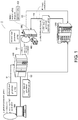
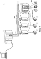
- FIG. 1 is a schematic diagram showing an example of an application scene of a control system 1 according to the embodiment.
- the control system 1 according to the embodiment provides, for example, a safety function for a drive apparatus and a function for transferring (downloading), to a safety driver, SRA parameters defined in an ETG standard determined in Non-Patent literature 1 described above.
- the control system 1 mainly includes a standard controller 100, and a safety controller 200 and one or more safety drivers 300 connected to the standard controller 100 via a field network.
- Each of the safety drivers 300 is an example of a drive apparatus and drives an electrically connected servomotor 400.
- any kind of actuator for example, a three-phase AC motor, a DC motor, a single-phase AC motor, a multi-phase AC motor, a linear servo, or the like
- the substance of the safety driver 300 may be a servo driver or a general-purpose inverter apparatus. In the following description, the safety driver 300 is described as an example of the drive apparatus.
- the standard controller 100 corresponds to a first controller and executes standard control for an object to be controlled including the servomotor 400 according to a standard control program created in advance.
- the standard controller 100 cyclically executes a control calculation according to an input signal from one or more sensors (not shown) or the like, thereby periodically calculating an instruction (first instruction) to the actuator such as the servomotor 400 or the like.
- the safety controller 200 transmits a safety instruction (second instruction) related to the work of the safety function to the safety driver 300. More specifically, independently of the standard controller 100, the safety controller 200 cyclically executes monitoring and control calculations for implementing the safety function for the object to be controlled.
- the safety controller 200 can receive an input signal from an arbitrary safety device 240 described later, and/or output an instruction to the arbitrary safety device 240.
- standard control mainly carried by the standard controller 100 and “safety control” carried by the safety controller 200 or the safety driver 300 are used in contrast.
- the “standard control” is a general term of processing for controlling the object to be controlled according to a predetermined requirement specification.
- safety control is a general term of processing for preventing human safety from being threatened by equipment or machines.
- the “safety control” is designed to meet requirements for implementing a safety function determined in IEC 61508 and the like.
- the safety driver 300 drives the servomotor 400 by supplying electric power to the servomotor 400 in accordance with the instruction (the first instruction) from the standard controller 100.
- the safety driver 300 periodically calculates a rotation position, a rotation speed, a rotation acceleration, a generated torque, and the like of the servomotor 400 based on a feedback signal from the servomotor 400 and the like.
- the safety driver 300 provides the safety controller 200 with state information necessary for the safety function, and executes a motion safety program 3202 according to the required safety function to adjust or shut off the electric power supplied to the servomotor 400 and monitor or adjust a position and a speed of a control shaft of the servomotor 400.
- the motion safety program 3202 adjusts or shuts off this electric power by with reference to the parameter group stored in a region E2, and also monitors and adjusts this electric power.
- the parameter group includes one or more SRA parameters that indicate values for motion safety (a position, a speed, a range, and the like).
- the servomotor 400 has a motor rotated by receiving the electric power from the safety driver 300 and outputs, to the safety driver 300, a detection signal from an encoder coupled to a rotation shaft of the motor as the feedback signal.
- the safety driver 300 compares the values of the parameter group in the region E2 with the feedback from the encoder of the servomotor 400, and thereby monitoring that the servomotor 400 is normally controlled. As long as the safety driver 300 controls normally, normal work can be continued. When the safety driver 300 judges that the control on the servomotor 400 is incorrect, a stop signal from the safety driver 300 to the servomotor 400 is output.
- the parameter group in the region E2 which is a judgment reference for the safety driver 300 includes important parameters for the safety control.
- the parameter group may be changed by, for example, set-up change or the like.
- the parameter group in the region E2 is transferred to the safety driver 300 via the field network from a support apparatus 500 connectable to the field network.
- the support apparatus 500 generates a parameter group in accordance with a user operation for this support apparatus, and when the generated parameter group is transferred to the safety driver 300, a size of this generated parameter group is reduced in a way capable of restoring the parameter group by the safety driver 300. Accordingly, the "reduced-size parameter group" is generated, and the "reduced-size parameter group” is transferred to the safety driver 300 via the field network (flows S1 and S3).
- the "reduced-size parameter group" instead of the generated full-size parameter group is transferred to the safety driver 300, and thereby a communication load such as time or the like associated with the transfer can be reduced.
- a communication load such as time or the like associated with the transfer
- time associated with the transfer of the parameter group can be shortened, time required for starting up the control system 1, such as time when a power source of a manufacturing apparatus is turned on, can be shortened.
- the safety driver 300 uses the "reduced-size parameter group"
- the safety driver 300 restores the original parameter group (that is, the parameter group generated by the support apparatus 500) from the "reduced-size parameter group” and stores the restored parameter group in the region E2.
- the control system 1 provides a mechanism for detecting validity of the restored parameter group.
- the safety driver 300 calculates cyclic redundancy check (CRC) data from the restored parameter group.
- the support apparatus 500 generates "CRC data of the generated parameter group” from the generated parameter group and transfers the "CRC data of the generated parameter group” to the safety controller 200 (flow S2).
- the safety controller 200 transmits the "CRC data of the generated parameter group” to the safety driver 300 together with an establishment request of a logic connection 4 to the safety driver 300.
- the safety driver 300 compares the CRC data of the restored parameter group with the "CRC data of the generated parameter group" received together with the establishment request.
- the safety driver 300 establishes a logic connection to the safety controller 200 in response to the request, and executes the motion safety program 3202 with reference to the restored parameter group in the region E2. Accordingly, even if the parameter group may contain errors or alterations in the process of size reduction, the process of transfer, or the process of restoration, in the safety driver 300, the motion safety program 3202 is guaranteed to be executed with reference to the parameter group whose validity has been confirmed.
- control system 1 As a more specific application example of the present invention, a more detailed configuration and more detailed processing of the control system 1 according to the embodiment are described.
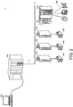
- FIG. 2 is a schematic diagram showing the configuration example of the control system 1 according to the embodiment.
- the control system 1 mainly includes the standard controller 100, and the safety controller 200 and the one or more safety drivers 300 connected to the standard controller 100 via the field network.
- Each of the safety drivers 300 drives the electrically connected servomotor 400.
- any kind of motor can be employed.
- the standard controller 100 executes the standard control for the object to be controlled including the servomotor 400 according to the standard control program created in advance. Typically, the standard controller 100 cyclically executes the control calculation according to the input signal from the one or more sensors (not shown) or the like, thereby periodically calculating the instruction to the actuator such as the servomotor 400 or the like.
- the safety controller 200 cyclically executes the monitoring and the control calculations for implementing the safety function for the object to be controlled.
- the safety controller 200 can receive an input signal from any safety device 240, and/or output an instruction to the arbitrary safety device 240.
- the safety driver 300 drives the servomotor 400 by supplying the electric power to the servomotor 400 in accordance with the instruction from the standard controller 100.
- the safety driver 300 periodically calculates the rotation position, the rotation speed, the rotation acceleration, the generated torque, and the like of the servomotor 400 based on the feedback signal from the servomotor 400 and the like.
- the safety driver 300 provides the safety controller 200 with the state information necessary for the safety function, and adjusts or shuts off the electric power supplied to the servomotor 400 according to the required safety function.
- the servomotor 400 has the motor rotated by receiving the electric power from the safety driver 300 and outputs, to the safety driver 300, the detection signal from the encoder coupled to the rotation shaft of the motor as the feedback signal.
- FIG. 3 is a schematic diagram showing a hardware configuration example of the standard controller 100 configuring the control system 1 according to the embodiment.
- the standard controller 100 includes a processor 102, a main memory 104, a storage 110, an upper network controller 106, a field network controller 108, a universal serial bus (USB) controller 120, a memory card interface 112, and a local bus controller 116. These components are connected via a processor bus 118.
- the processor 102 corresponds to a calculation processing portion that mainly executes the control calculations related to the standard control, and is configured by a central processing unit (CPU), a graphics processing unit (GPU), and the like. Specifically, the processor 102 reads programs stored in the storage 110 (for example, a system program 1102 and a standard control program 1104), expands these programs into the main memory 104, and executes these programs, thereby implementing the control calculation according to the object to be controlled and various processes as described later.
- programs stored in the storage 110 for example, a system program 1102 and a standard control program 1104
- the main memory 104 is configured by a volatile storage apparatus such as a dynamic random access memory (DRAM), a static random access memory (SRAM), or the like.
- the storage 110 is configured by, for example, a non-volatile storage apparatus such as a solid state drive (SSD), a hard disk drive (HDD), or the like.
- the storage 110 in addition to the system program 1102 for implementing basic functions, the standard control program 1104 created according to the object to be controlled is stored. In addition, the storage 110 stores setting information 1106 for setting various variables.
- the upper network controller 106 exchanges data with any information processing apparatus via the upper network.
- the field network controller 108 exchanges data with any device including the safety controller 200 and the safety driver 300 via the field network 2.
- the field network controller 108 of the standard controller 100 functions as a communication master of a field network 2.
- the USB controller 120 exchanges data with the support apparatus 500 and the like via a USB connection.
- the memory card interface 112 receives a memory card 114, which is an example of a removable recording medium.
- the memory card interface 112 can write data to the memory card 114 and read various data (logs, trace data, and the like) from the memory card 114.
- the local bus controller 116 exchanges data with any unit connected to the standard controller 100 via a local bus.
- the support apparatus 500 is arranged independently of the standard controller 100, but a configuration in which functions of a display apparatus, the support apparatus 500, and the like are integrated with the standard controller 100 may be employed.
- FIG 3 shows a configuration example in which necessary functions are provided in a manner that the processor 102 executes the programs.
- some or all of these functions provided may be implemented using a dedicated hardware circuit (for example, an application specific integrated circuit (ASIC), a field-programmable gate array (FPGA), or the like).
- a main part of the standard controller 100 may be implemented using hardware that follows a general-purpose architecture (for example, an industrial personal computer based on a general-purpose personal computer).
- virtualization technology may be used to execute a plurality of operating systems (OSs) for different purposes in parallel, and to execute necessary applications on each OS.
- OSs operating systems
- a configuration may be employed in which the functions of the display apparatus, the support apparatus, and the like are integrated into the standard controller 100.
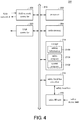
- FIG. 4 is a schematic diagram showing a hardware configuration example of the safety controller 200 configuring the control system 1 according to the embodiment.
- the safety controller 200 includes a processor 202, a main memory 204, a storage 210, a field network controller 208, a USB controller 220, and a safety local bus controller 216. These components are connected via a processor bus 218.
- the processor 202 corresponds to a calculation processing portion that mainly executes the control calculations related to the safety control, and is configured by a CPU, a GPU, and the like. Specifically, the processor 202 reads programs stored in the storage 210 (for example, a system program 2102 and a safety program 2104), expands these programs into the main memory 204, and executes these programs, thereby implementing the control calculation for providing the necessary safety functions and various processes as described later.
- programs stored in the storage 210 for example, a system program 2102 and a safety program 2104
- the main memory 204 is configured by a volatile storage apparatus such as a DRAM, a SRAM, or the like.
- the storage 210 is configured by, for example, a non-volatile storage apparatus such as a SSD, a HDD, or the like.
- the storage 210 in addition to the system program 2102 for implementing basic functions, the safety program 2104 created according to the required safety functions is stored. Furthermore, the storage 210 stores setting information 2106 for setting variables and the like.
- the field network controller 208 exchanges data with any device including the standard controller 100 and the safety driver 300 via the field network 2.
- the field network controller 208 of the safety controller 200 functions as a communication slave of the field network 2.
- the USB controller 220 exchanges data with the information processing apparatus such as the support apparatus 500 and the like via a USB connection.
- the safety local bus controller 216 exchanges data with any safety unit connected to the safety controller 200 via a safety local bus.
- FIG. 4 shows a safety IO unit 230 as an example of the safety unit.
- the safety IO unit 230 exchanges input/output signals with any safety device 240. More specifically, the safety IO unit 230 receives an input signal from a safety device 240 such as a safety sensor, a safety switch, or the like. Alternatively, the safety IO unit 230 outputs an instruction to a safety device 240 such as a safety relay, or the like.
- a safety device 240 such as a safety sensor, a safety switch, or the like.
- FIG. 4 shows a configuration example in which necessary functions are provided in a manner that the processor 202 executes the programs.
- some or all of these functions provided may be implemented using a dedicated hardware circuit (for example, an ASIC, a FPGA, or the like).
- a main part of the safety controller 200 may be implemented using hardware that follows a general-purpose architecture (for example, an industrial personal computer based on a general-purpose personal computer).
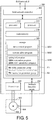
- FIG. 5 is a schematic diagram showing a hardware configuration example of the safety driver 300 and the servomotor 400 configuring the control system 1 according to the embodiment.
- the safety driver 300 includes a field network controller 302, a control portion 310, a drive circuit 330, and a feedback reception circuit 332.
- the field network controller 302 exchanges data with any device, including the standard controller 100 and the safety controller 200, via the field network 2.
- the field network controller 302 of the safety driver 300 functions as a communication slave of the field network 2.
- the control portion 310 executes calculation processing necessary for causing the safety driver 300 to work.
- the control portion 310 includes processors 312 and 314, a main memory 316, and a storage 320.
- the processor 312 corresponds to a calculation processing portion that mainly executes control calculation for driving the servomotor 400.
- the processor 314 corresponds to a calculation processing portion that mainly executes control calculation for providing the safety function related to the servomotor 400.
- the processors 312 and 314 are both configured by CPUs or the like.
- the main memory 316 is configured by a volatile storage apparatus such as a DRAM, a SRAM, or the like.
- the storage 320 is configured by, for example, a non-volatile storage apparatus such as a SSD, a HDD, or the like.
- the storage 320 stores a servo control program 3201 for implementing servo control related to the servomotor 400, the motion safety program 3202 for implementing the motion safety function related to the servomotor 400, and setting information 3206 for setting variables and the like exposed to other devices.
- the storage 320 further includes a region E1 for holding (storing) an initial parameter group 60 indicating initial values of the SRA parameters and the region E2 for storing a restoration parameter group 70.
- the restoration parameter group 70 shows a parameter group generated by restoring a parameter group after change whose size has been reduced to an original parameter group after change.
- the setting information 3206 includes a restoration program 3204 executed by the processor 314 and a CRC calculation program 3205 that calculates cyclic redundancy check (CRC) data.
- the restoration program 3204 executes, the processing of restoring the reduced-size change parameter group is carried out, and the restoration parameter group 70 obtained by the restoration is stored in the region E2.
- the "restoration” includes processing of returning the reduced-size change parameter group to the original size without damaging the contents of this change parameter group.
- the "contents of the parameter group” include the number of parameters, an identifier (name) of each parameter, a data type, a data length, values (numerical value, logic value, etc.), and the like.
- the CRC calculation program 3205 calculates CRC data (value) for error detection from the restoration parameter group 70 in the region E2 in accordance with a predetermined calculation formula.
- the CRC data is a value for detecting validity of the restoration parameter group 70, such as that the restoration parameter group 70 has no error (or alteration), and the CRC data may include, for example, a checksum calculated from binary data of the restoration parameter group 70, or the like. Moreover, the CRC data is not limited to the checksum.
- FIG. 5 exemplifies a configuration in which the two processors 312 and 314 execute the control calculations for different purposes to improve reliability, but the configuration is not limited hereto, and any configuration may be employed as long as the required safety function can be implemented. For example, when a plurality of cores are contained in a single processor, the control calculations respectively corresponding to the processors 312 and 314 may be executed.
- FIG. 5 shows a configuration example in which the necessary functions are provided in a manner that the processors 312 and 314 executes the program. However, some or all of these functions provided may be implemented using a dedicated hardware circuit (for example, ASIC, FPGA, or the like).
- the drive circuit 330 includes a converter circuit, an inverter circuit, and the like, generates electric power having a specified voltage, current, and phase according to an instruction from the control portion 310, and supplies the electric power to the servomotor 400.
- the feedback reception circuit 332 receives the feedback signal from the servomotor 400 and outputs the reception result to the control portion 310.
- the servomotor 400 typically includes a three-phase AC motor 402 and an encoder 404 mounted on a rotation shaft of the three-phase AC motor 402.
- the three-phase AC motor 402 is an actuator that receives the electric power supplied from the safety driver 300 to generate a rotation force.
- FIG. 5 exemplifies a three-phase AC motor as an example, but the present invention is not limited hereto, and a DC motor, a single-phase AC motor, or a multi-phase AC motor may be used. Furthermore, an actuator that generates a driving force along a straight line such as a linear servo may be employed.
- the encoder 404 outputs a feedback signal (typically, a number of pulse signals corresponding to the rotation speed) corresponding to the rotation speed of the three-phase AC motor 402.
- FIG. 6 is a schematic diagram showing a hardware configuration example of the support apparatus 500 configuring the control system 1 according to the embodiment.
- the support apparatus 500 is implemented using hardware (for example, a general-purpose personal computer) that follows a general-purpose architecture.
- the support apparatus 500 includes a processor 502, a main memory 504, an input portion 506, an output portion 508, a storage 510, an optical drive 512, and a USB controller 520, which is an example of a communication interface. These components are connected via a processor bus 518.
- the processor 502 is configured by a CPU, a GPU, and the like, reads a program stored in the storage 510, expands the program in the main memory 504, and executes the program, thereby implementing various processes as described later.
- the main memory 504 is configured by a volatile storage apparatus such as a DRAM, a SRAM, or the like.
- the storage 510 is configured by, for example, a non-volatile storage apparatus such as a HDD, a SSD, or the like.
- a support program 5104 for providing the function as the support apparatus 500 is stored in the storage 510. That is, the support program 5104 is executed by the processor of the information processing apparatus connected to the control system 1, and thereby the support apparatus 500 according to the embodiment is implemented.
- the storage 510 includes a region E3 for holding (storing) the initial parameter group 60 and a region E4 for storing a change parameter group 65.
- the support program 5104 is executed so as to provide various development environments (tools and the like).
- the support program 5104 includes a parameter generation program 5105, a size reduction program 5106, and a CRC calculation program 5107 that provide the tools for generating the parameter group.
- the parameter generation program 5105 generates the change parameter group 65 by changing the contents of the initial parameter group 60 in accordance with the user operation received via the input portion 506.
- the generated change parameter group 65 is stored in the region E4.
- the size reduction program 5106 provides a tool for generating, from the change parameter group 65 in the region E4, a parameter group having a size smaller than a data size of this change parameter group 65. Furthermore, when the size reduction program 5106 reduces the size of the change parameter group 65, the size reduction is carried out in order that the change parameter group 65 can be restored by the restoration program 3204 of the safety driver 300.
- the CRC calculation program 510 calculates CRC data (value) for error detection from the initial parameter group 60 in the region E3 or the change parameter group 65 in the region E4 in accordance with a predetermined calculation formula.
- the CRC data is a value for detecting validity of this parameter group, such as that the initial parameter group 60 or the change parameter group 65 has no error (or alteration).
- the predetermined calculation formula applied to the CRC calculation program 5107 match the calculation formula applied to the CRC calculation program 3205 of the safety driver 300.
- the input portion 506 is configured by a keyboard, a mouse, and the like, and receives the user operation on the support apparatus 500.
- the output portion 508 is configured by a display, various indicators, a printer, and the like, and outputs a processing result from the processor 502 and the like.
- the USB controller 520 can be connected to the field network 2, and exchanges data with, for example, the standard controller 100 and the like via the USB connection.
- the support apparatus 500 has the optical drive 512, and from a recording medium 514 (for example, an optical recording medium such as a digital versatile disc (DVD) or the like) that non-transiently stores a computer-readable program, a program stored in the recording medium 514 is read and installed in the storage 510 or the like.
- a recording medium 514 for example, an optical recording medium such as a digital versatile disc (DVD) or the like
- DVD digital versatile disc
- the support program 5104 or the like executed by the support apparatus 500 may be installed via the computer-readable recording medium 514, or may be installed in a form of being downloaded from a server apparatus or the like on the network.
- the functions provided by the support apparatus 500 according to the embodiment may also be implemented in a form of using a part of modules provided by the OS.
- FIG. 6 shows a configuration example in which necessary functions are provided to form the support apparatus 500 in a manner that the processor 502 executes the programs.
- some or all of these functions provided may be implemented using a dedicated hardware circuit (for example, an ASIC, a FPGA, or the like).
- the support apparatus 500 may be removed from the standard controller 100 during running of the control system 1.
- FIG. 7 is a diagram for illustrating a transmission mode of a communication frame in the control system 1 according to the embodiment.
- data communication is performed in the field network 2 of the control system 1, and the communication frame 600 cyclically (for example, several to tens of msec) goes round the devices by using the standard controller 100 as the communication master.
- a period at which the communication frame 600 is transmitted is also referred to as a process data communication period.
- EtherCAT registered trademark
- EtherCAT registered trademark
- a data region is allocated to the communication frame 600 for each device.
- each device receives the communication frame 600, each device writes a current value of the preset data in the data region allocated to the device in this received communication frame 600. Then, the communication frame 600 after writing the current value is sent to the next device.
- the current value of the data written by each device can be referenced from other devices.
- Each device writes the current value of the preset data in the communication frame 600, and thereby, the latest value collected by each device is included in the communication frame 600 which goes around the field network 2 and returns to the communication master (the standard controller 100).
- this data communication is used, and the logic connection 4 is formed between each of the safety controller 200 and the safety driver 300 (see FIG. 7 ).
- the logic connection 4 is used for exchanging data to implement the safety functions.
- the logic connection 4 can be formed using a FSoE protocol.
- FIG. 8 is a schematic diagram showing an example of the function sharing during the running of the control system 1 according to the embodiment.
- the safety driver 300 executes a servo control 350 with respect to a standard control 150 executed by the standard controller 100.
- the standard control 150 includes processing of periodically calculating an instruction for driving the servomotor 400 according to a user program preset for the object to be controlled.
- the servo control 350 includes control for driving the servomotor 400 according to an instruction periodically calculated by the standard control 150, and processing of acquiring and outputting a state value indicating a work state of the servomotor 400.
- the servo control 350 is handled by the processor 312 (see FIG. 5 ) of the safety driver 300.
- the safety driver 300 provides a motion safety function 360 in response to a safety function 250 provided by the safety controller 200.
- the motion safety function 360 is handled by processor 314 (see FIG. 5 ) of the safety driver 300.
- the safety function 250 activates the safety function specified in advance.
- Processing of activating the safety function specified in advance includes, for example, the output of the safety instruction to the safety driver 300, the output of the safety instruction to the safety device 240 (for example, shutting off safety relay related to the electric power supply to a predetermined apparatus), or the like.
- the safety driver 300 When the motion safety program 3202 is executed, the safety driver 300 provides the specified motion safety function 360 in response to the safety instruction from the safety controller 200. Depending on the type of the specified motion safety function 360, with intervention of the control on the servomotor 400 by the servo control 350 which the servo control program 3201 carries out, processing of shutting off the electric power supply to the servomotor 400, processing of monitoring whether the state value of the control on the servomotor 400 by the servo control 350 is within a predetermined limit range, or other processing is executed.
- the motion safety program 3202 references the SRA parameters indicated by the initial parameter group 60 in the region E1 or the restoration parameter group 70 in the region E2 to shut off the supply of the electric power or carry out the processing of monitoring.
- the data communication and the safety communication by the logic connection 4 are possible.
- implementation examples of the standard control, the safety control, and the SRA parameter transfer using each communication are described.
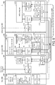
- FIG. 9 is a schematic diagram showing an implementation example of the standard control, the safety control, and the parameter transfer in the control system 1 according to the embodiment.
- FIG. 9 shows an example of the control system 1 including one safety driver 300 in addition to the standard controller 100, the safety controller 200 and the support apparatus 500.
- the standard controller 100 has, as main functional configurations, a data communication layer 170 and an IO management module 172.
- the safety controller 200 includes, as main functional configurations, a data communication layer 270, an IO management module 272, a logic connection layer 276, and a safety function state management engine 278.
- the safety driver 300 includes, as main functional configurations, a data communication layer 370, a logic connection layer 376, a motion safety function state management engine 378, a servo control execution engine 352, and a motion safety function execution engine 362.
- the safety driver 300 further includes a parameter manager 371 that manages various parameters including the SRA parameter group.
- the data communication layer 170, the data communication layer 270, and the data communication layer 370 handle the transfer of the communication frame 600 on the field network 2.
- the logic connection layer 276 of the safety controller 200 and the logic connection layer 376 of the safety driver 300 handle exchanging of a safety communication frame 630. That is, the logic connection layer 276 and the logic connection layer 376 use the safety communication frame 630 included in the communication frame 600 according to the protocol for establishing the logic connection (FSoE in the embodiment) to exchange the commands and the data.
- the safety controller 200 includes an establishment module 277 for establishing the logic connection 4 to the safety driver 300 via the logic connection layer 276.
- the IO management module 172 updates process data 174 by exchanging signals with the object to be controlled.
- the standard control program 1104 executed by the standard controller 100 executes the control calculation with reference to the process data 174, and updates the process data 174 with the execution result of the control calculation.
- the IO management module 272 updates process data 274 by exchanging signals with the safety device 240.
- the safety program 2104 executed by the safety controller 200 executes the control calculation with reference to the process data 274 and the safety function state management engine 278, and updates the process data 274 or outputs an internal instruction to the safety function state management engine 278 based on the execution result of the control calculation.
- the safety function state management engine 278 generates an instruction for activating a specific motion safety function for the specific safety driver 300 according to the execution result of the control calculation by the safety program 2104.
- the logic connection layer 276 exchanges necessary commands and information with the logic connection layer 376 of the safety driver 300 which is the target by using the safety communication frame 630.
- the servo control execution engine 352 executes the control calculation related to the servo control with reference to process data 374 and the information of the feedback signal acquired via the feedback reception circuit 332.
- the servo control execution engine 352 updates the process data 374 and outputs an internal instruction to the drive circuit 330 based on the execution result of the control calculation.
- the drive circuit 330 drives the servomotor 400 according to the instruction from the servo control execution engine 352.
- the motion safety function state management engine 378 manages a state of the motion safety function according to the safety instruction from the safety controller 200.
- the motion safety function state management engine 378 outputs an internal instruction to the motion safety function execution engine 362 in response to the instruction the safety controller 200.
- the specified motion safety function is implemented by executing the motion safety program 3202.
- the logic connection layer 376 exchanges the necessary commands and information with the logic connection layer 276 of the safety controller 200 by using the safety communication frame 630 in response to the instruction from the motion safety function state management engine 378.
- the parameter manager 371 the logic connection layer 376 implements a CRC data calculation function by executing the CRC calculation program 3205, and implements a function of comparing the calculated CRC data with the CRC data received from the safety controller 200.
- the parameter manager 371 causes the logic connection layer 376 to transmit a response of establishing the logic connection 4 to the safety controller 200.
- the support apparatus 500 has, as main functional configurations, a data communication layer 533 and a parameter manager 532.
- the data communication layer 533 exchanges data with various apparatuses including the standard controller 100.
- the parameter manager 532 By executing the parameter generation program 5105, the parameter manager 532 generates a parameter group in accordance with the user operation contents received by an operation reception portion 530 via the input portion 506.
- the parameter manager 532 reduces the size of the generated parameter group by executing the size reduction program 5106.
- the parameter manager 532 implements the function of transferring the reduced-size parameter group to the safety driver 300 which is the object via the field network 2.
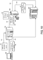
- FIG. 10 is a schematic diagram showing an example of a transfer flow of the reduced-size parameter group in the control system 1 according to the embodiment.
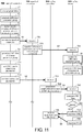
- FIG. 11 is a schematic diagram showing an example of a transfer sequence of the reduced-size parameter group in the control system 1 according to the embodiment.
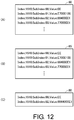
- FIG. 12 is a diagram illustrating a way of deriving a difference parameter group according to the embodiment.
- the SRA parameter group is transferred from the support apparatus 500 to each safety driver 300.
- the support apparatus 500 reduces the size of the generated parameter group, that is, the change parameter group 65 in the region E4, and transfers the reduced-size parameter group to each safety driver 300 via the field network 2.
- a difference parameter group 80 can be applied as the reduced-size parameter group.
- the parameter manager 532 executes the size reduction program 5106, and thereby a difference between the change parameter group 65 and the initial parameter group 60 is extracted and the difference parameter group 80 in FIG. 12(C) indicating the difference is generated.
- the contents of the parameter group shown in FIG. 12 include, for each parameter, a storage location (a physical address or a logic address) indicated by Index and subIndex, an identifier (a name or the like) indicated by 00, 01, 02 or the like, and a value indicated by Value.
- the data size of the difference parameter group 80 can be made smaller than the data size of the change parameter group 65 by the size reduction.
- the sequence for transferring the difference parameter group 80 to each safety driver 300 is described with reference to FIGS. 10 and 11 .
- Flows S1 to S5 in FIG. 11 correspond to flows S1 to S5 in FIG. 10 .
- the parameter manager 532 executes the parameter generation program 5105, thereby changing the initial parameter group 60 in accordance with the user operation received by the operation reception portion 530.
- the change parameter group 65 is generated (step T1 in FIG. 11 ).
- the parameter manager 532 executes the size reduction program 5106, and thereby the difference parameter group 80 as shown in FIG. 12 is generated (step T3).
- the parameter manager 532 sets the transfer command of the difference parameter group 80 in the EtherCAT initialization command of the safety driver 300 (slave) (step T5).
- the support apparatus 500 transfers the initialization command to the standard controller 100 together with the difference parameter group 80 (step T7).
- the parameter manager 532 of the support apparatus 500 calculates CRC data 85 from the change parameter group 65 (step T9), sets the CRC data 85 in the connection parameter, and transmits this connection parameter to the safety controller 200 via the field network 2 (steps T11 and T13).
- the standard controller 100 receives the difference parameter group 80 and the initialization command from the support apparatus 500 (step T21), and transfers the difference parameter group 80 to the safety driver 300 by executing the transfer command set in the initialization command to turn. (step T23).
- the safety driver 300 receives the difference parameter group 80 from the standard controller 100 via the field network 2 (step T41).
- the parameter manager 371 changes the initial parameter group 60 read from the region E1 by using the received difference parameter group 80. Accordingly, the restoration parameter group 70 that restores the change parameter group is generated, and the restoration parameter group 70 is stored in the region E2 (step T43).
- the transfer can be completed by transferring the difference parameter group 80 instead of transferring all the parameters of the change parameter group 65, time related to the transfer can be shortened, and the load on the field network 2 can be reduced.
- the parameter manager 371 of the safety driver 300 calculates CRC data 90 from the restoration parameter group 70 in the region E2 by executing the CRC calculation program 3205 (step T45).
- a connection establishment request is transferred to the safety driver 300 together with the CRC data 85 set in the connection parameter received from the support apparatus 500 (steps T31 and T33).
- the parameter manager 371 of the safety driver 300 compares the CRC data 85 received together with the connection establishment request with the CRC data 90 generated in step T45 (step T49).
- the safety driver 300 judges that the comparison result indicates a match (YES in step T51)
- the safety driver 300 receives the establishment request, generates an "OK” response and transmits the "OK” response to the safety controller 200 (step T53). Thereafter, the logic connection 4 is established between the safety driver 300 and the safety controller 200.
- the safety driver 300 judges that the comparison result indicates a mismatch (NO in step T51)
- the safety driver 300 generates an "NG" response for rejecting the establishment request and transmits the "NG” response to the safety controller 200 (step T55).
- the establishment module 277 of the safety controller 200 receives the OK or NG response from the safety driver 300 in response to the establishment request (step T35).
- the safety driver 300 can detect, by carrying out CRC code comparison, that there is an error, an alteration or the like in the size reduction process, the process of transferring the difference parameter group 80, or the process of restoration using the difference parameter group 80.
- the motion safety program 3202 can be executed with reference to the initial parameter group 60 instead of the restoration parameter group 70. Thereby, the motion safety program 3202 can be prevented from being executed with reference to a parameter group that may have an error.
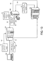
- FIG. 13 is a schematic diagram showing another example of the transfer flow of the reduced-size parameter group in the control system 1 according to the embodiment.
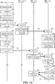
- FIG. 14 is a schematic diagram showing another example of the transfer sequence of the reduced-size parameter group in the control system 1 according to the embodiment.
- the size reduction of the change parameter group 65 is implemented by generating the difference parameter group 80, but as another way of the size reduction, a way of compressing the change parameter group 65 may be used.
- a sequence of transferring a compressed parameter group 75 is described with reference to FIGS. 13 and 14 , and the compressed parameter group 75 is obtained by compressing the change parameter group 65 in order to transfer the change parameter group 65 to each safety driver 300.
- Flows S1 to S5 in FIG. 14 correspond to flows S1 to S5 in FIG. 13 .
- the parameter manager 532 of the support apparatus 500 generates the change parameter group 65 by changing the initial parameter group 60 in accordance with the user operation received by the operation reception portion 530 (step T1 in FIG. 14 ), and stores the change parameter group 65 in the region E4.
- the parameter manager 532 compresses the change parameter group 65 read from the region E4 by a predetermined compression method by executing the size reduction program 5106, and generates the compressed parameter group 75 (step T3a).
- a predetermined compression method for example, ZIP can be employed.
- the support apparatus 500 sets a transfer command of the compressed parameter group 75 in the EtherCAT initialization command of the safety driver 300 (slave) (step T5a).
- the support apparatus 500 transfers the initialization command to the standard controller 100 together with the compressed parameter group 75 (step T7).
- the parameter manager 532 of the support apparatus 500 calculates the CRC data 85 from the change parameter group 65 (step T9), sets CRC data 85 in the connection parameter (step T11), and transmits the connection parameters to the safety controller 200 via the field network 2 (step T13).
- the standard controller 100 receives the compressed parameter group 75 together with the initialization command from the support apparatus 500 (step T21), and transfers the compressed parameter group 75 to the safety driver 300 by executing the transfer command set in the initialization command (step T23a).
- the safety driver 300 receives the compressed parameter group 75 from the standard controller 100 (step T41), and the parameter manager 371 executes the restoration program 3204, thereby restoring the received compressed parameter group 75 according to a decompression (extension, expansion) method corresponding to the above-mentioned predetermined compression method, and generates the restoration parameter group 70.
- the generated restoration parameter group 70 is stored in the region E2 (step T43a).
- the transfer can be completed by compressing and size-reducing the change parameter group 65, the time related to the transfer can be shortened, and the load on the field network 2 can be reduced.
- steps T31 to T55 are executed between the support apparatus 500, the safety controller 200, and the safety driver 300. Because the processes of steps T31 to T55 in FIG. 14 are the same as those processes shown in FIG. 11 , the description is not repeated.
- the compression method a method selected from a plurality of methods including the above ZIP can also be used.
- the parameter manager 532 of the support apparatus 500 transmits, to the safety driver 300, a command of specifying the decompression method corresponding to the selected compression method.
- the parameter manager 371 of the safety driver 300 decompresses the compressed parameter group 75 according to the decompression method specified by the command received from the safety driver 300.
- the support apparatus 500 transmits the command of specifying the decompression method to the safety driver 300 via the field network 2.
- the command of specifying the decompression method may be transmitted to the safety driver 300 together with the compressed parameter group 75 transferred to the safety driver 300 or at a time different from the transfer of the compressed parameter group 75.
- the specifying command may be included in a header of the compressed parameter group.
- the difference parameter group 80 may indicate the difference between the binary data of the initial parameter group 60 and the change parameter group 65, and may indicate a difference between the CSV data when the parameter group follows the CSV format as shown in FIG. 12 .
- the difference parameter group 80 is transferred to the safety driver 300 through the standard controller 100 ( FIG. 11 ), and the compressed parameter group 75 and the command of specifying the decompression method are transferred to the safety driver 300 through the standard controller 100 ( FIG. 14 ), but the transferring route is not limited hereto.
- the difference parameter group 80 may be transferred from the support apparatus 500 to the safety driver 300 without going through the standard controller 100, and the compressed parameter group 75 and the command of specifying the decompression method may also be transferred from the support apparatus 500 to the safety driver 300 without going through the standard controller 100.
Landscapes
- Physics & Mathematics (AREA)
- General Physics & Mathematics (AREA)
- Engineering & Computer Science (AREA)
- Automation & Control Theory (AREA)
- Programmable Controllers (AREA)
- Control Of Electric Motors In General (AREA)
- Safety Devices In Control Systems (AREA)
Abstract
Description
- The disclosure relates to a control system, a support apparatus and a program applied to a factory automation (FA) system arranged at a manufacturing site or the like.
- In FA systems at many manufacturing sites, introduction of a safety system is progressing in order to use equipment and machines safely. The safety system is used for providing a safety function in accordance with international standards, and is configured by safety components such as a safety controller, a safety sensor, a safety switch, and a safety relay.
- The safety system is also required to provide a safety function for a drive apparatus such as a servomotor that drives the equipment or the machines. In order to implement the safety function, a safety driver that controls the drive apparatus executes a safety program. At execution time, the safety program references a parameter group. The parameter group for implementing this safety function is provided by being downloaded to the safety driver.
- For example, Non-Patent
literature 1 proposes FSoE (Safety over EtherCAT) which is a mechanism for mixing safety control data related to a safety system with data on an EtherCAT (registered trademark) (EtherCAT: Ethernet (registered trademark) for Control Automation Technology) communication path. - [Non-Patent literature 1] "EtherCAT Protocol Enhancements, Amendments to ETG. 5100 FSoE specification, Document: ETG. 5120 S(R)V1.1.0", EtherCAT Technology Group, 2017-07-14
- Non-Patent
literature 1 discloses a mechanism for transferring (downloading), to FSoE slaves which are safety drivers, parameters of safty-related application parameter set (SRA) that the safety program references at the time of execution. When the SRA parameters are transferred to all the FSoE slaves connected to the system, a communication load, including the transfer time, increases in proportion to the number of the FSoE slaves. - One object of the disclosure is to provide a control system, a support apparatus and a program that reduce a load associated with transfer of parameters referenced by a safety program in a control system.
- The control system according to an example of the disclosure includes: a first controller; and a drive apparatus for driving a motor in accordance with a first instruction from the first controller. The drive apparatus includes a memory that stores a safety program for implementing a safety function relating to the drive of the motor, and a parameter group referenced at the time of the execution of the safety program. The control system further includes: a second controller that transmits a second instruction related to work of the safety function to the drive apparatus; a network for sharing data with each other between the first controller, the drive apparatus, and the second controller; and a support apparatus capable of being connected to the network. The support apparatus includes a parameter generation portion that generates the parameter group in accordance with a user operation on this support apparatus, and a size reduction portion that reduces a size of the generated parameter group in a way capable of restoring the parameter group by the drive apparatus when the generated parameter group is transferred via the network.
- According to the disclosure, when the parameter group generated by the support apparatus is transferred to the drive apparatus, the parameter group is transferred after the size reduction. Thus, the load associated with the transfer of the parameter group to the drive apparatus can be reduced,
- In the above disclosure, the parameter generation portion generates a change parameter group changed in accordance with the user operation from an initial parameter group; and the size reduction portion generates, as the reduced-size parameter group, a difference parameter group indicating a difference between the change parameter group and the initial parameter group.
- According to the disclosure, the size reduction of the parameter group can be carried out by generating the difference parameter group indicating the difference between the initial parameter group used for the generation and the generated parameter group.
- In the above disclosure, the memory of the drive apparatus has a region for holding the initial parameter group; and the drive apparatus restores the change parameter group by changing the initial parameter group held in the memory using the difference parameter group received via the network.
- According to the disclosure, the drive apparatus can restore the generated parameter group (that is, the change parameter group) by using the held initial parameter group and the difference parameter group received from the support apparatus.
- In the above disclosure, the parameter generation portion generates a change parameter group changed in accordance with the user operation from an initial parameter group; and the size reduction portion generates a compressed change parameter group as the reduced-size parameter group.
- According to the disclosure, the size reduction of the parameter group can be carried out by compressing the generated parameter group.
- In the above disclosure, the drive apparatus restores the change parameter group by decompressing the compressed change parameter group received via the network.
- According to the disclosure, the drive apparatus can restore the generated parameter group (that is, the change parameter group) by decompressing the compressed parameter group received via the network.
- In the above disclosure, the drive apparatus restores the change parameter group by decompressing, in accordance with a command received via the network, the compressed change parameter group received via the network.
- According to the disclosure, the drive apparatus can restore the generated parameter group (that is, the change parameter group) by receiving the command and the compressed parameter group via the network and decompressing the compressed parameters in accordance with the received command.
- In the above disclosure, the second instruction is transmitted via a connection formed using the network between the second controller and the drive apparatus. The support apparatus includes a first calculation portion that calculates, from the change parameter group, first data indicating validity of this change parameter group in accordance with a predetermined formula, and the support apparatus transfers the calculated first data to the second controller. The drive apparatus includes a second calculation portion that calculates, from the restored change parameter group, second data indicating validity of this restored change parameter group in accordance with the predetermined formula, and notifies establishment of the connection to the second controller when comparison of the first data received from the second controller and the calculated second data indicates a match.
- According to the disclosure, when a value indicating the validity calculated from the change parameter group restored by the drive apparatus and a value indicating the validity calculated from the change parameter group generated by the support apparatus match, the connection can be established between the drive apparatus and the second controller.
- The support apparatus according to an example of the disclosure is connected to a control system. The control system includes: a first controller, and a drive apparatus for driving a motor in accordance with a first instruction from the first controller. The drive apparatus includes a memory that stores a safety program for implementing a safety function relating to the drive of the motor, and a parameter group referenced at the time of the execution of the safety program. The control system further includes: a second controller that transmits a second instruction related to work of the safety function to the drive apparatus, and a network for sharing data with each other between the first controller, the drive apparatus, and the second controller. The support apparatus includes: a parameter generation portion that generates the parameter group in accordance with a user operation on this support apparatus, and a size reduction portion that reduces a size of the generated parameter group in a way capable of restoring the parameter group by the drive apparatus when the generated parameter group is transferred via the network.
- According to the disclosure, when the parameter group generated by the support apparatus is transferred via the network, the parameter group is transferred after the size reduction. Thus, the load associated with the transfer of the parameter group to the drive apparatus can be reduced.
- The program according to an example of the disclosure is a program executed by an information processing apparatus connected to a control system. The control system includes: a first controller, and a drive apparatus for driving a motor in accordance with a first instruction from the first controller. The drive apparatus includes a memory that stores a safety program for implementing a safety function relating to the drive of the motor, and a parameter group referenced at the time of the execution of the safety program. The control system further includes: a second controller that transmits a second instruction related to work of the safety function to the drive apparatus, and a network for sharing data with each other between the first controller, the drive apparatus, and the second controller. The program causes a processor of the information processing apparatus to execute a step of generating the parameter group in accordance with a user operation on the information processing apparatus, and a step of reducing a size of this parameter group in a way capable of restoring the parameter group by the drive apparatus when the generated parameter group is transferred via the network.
- According to the disclosure, when the parameter group is transferred by executing the program, the parameter group is transferred after the size reduction. Thus, the load associated with the transfer of the parameter group to the drive apparatus can be reduced.
- According to an example of the disclosure, the load associated with the transfer of the parameters referenced by the safety program in the control system can be reduced.
-
-
FIG. 1 is a schematic diagram showing an example of an application scene of acontrol system 1 according to the embodiment. -
FIG. 2 is a schematic diagram showing a configuration example of thecontrol system 1 according to the embodiment. -
FIG. 3 is a schematic diagram showing a hardware configuration example of astandard controller 100 configuring thecontrol system 1 according to the embodiment. -
FIG. 4 is a schematic diagram showing a hardware configuration example of asafety controller 200 configuring thecontrol system 1 according to the embodiment. -
FIG. 5 is a schematic diagram showing a hardware configuration example of asafety driver 300 and aservomotor 400 configuring thecontrol system 1 according to the embodiment. -
FIG. 6 is a schematic diagram showing a hardware configuration example of asupport apparatus 500 configuring thecontrol system 1 according to the embodiment. -
FIG. 7 is a diagram illustrating a transmission mode of a communication frame in thecontrol system 1 according to the embodiment. -
FIG. 8 is a schematic diagram showing an example of function sharing during running of thecontrol system 1 according to the embodiment. -
FIG. 9 is a schematic diagram showing an implementation example of standard control, safety control, and parameter group transfer in thecontrol system 1 according to the embodiment. -
FIG. 10 is a schematic diagram showing an example of a transfer flow of a reduced-size parameter group in thecontrol system 1 according to the embodiment. -
FIG. 11 is a schematic diagram showing an example of a transfer sequence of the reduced-size parameter group in thecontrol system 1 according to the embodiment. -
FIG. 12 is a diagram illustrating a way of deriving a difference parameter group according to the embodiment. -
FIG. 13 is a schematic diagram showing another example of the transfer flow of the reduced-size parameter group in thecontrol system 1 according to the embodiment. -
FIG. 14 is a schematic diagram showing another example of the transfer sequence of the reduced-size parameter group in thecontrol system 1 according to the embodiment. - An embodiment of the present invention is described in detail with reference to the drawings. Moreover, the same or corresponding parts in the drawings are designated by the same reference signs and description thereof is not be repeated.
- First, an example of a scene in which the present invention is applied is described.
-
FIG. 1 is a schematic diagram showing an example of an application scene of acontrol system 1 according to the embodiment. Thecontrol system 1 according to the embodiment provides, for example, a safety function for a drive apparatus and a function for transferring (downloading), to a safety driver, SRA parameters defined in an ETG standard determined inNon-Patent literature 1 described above. - With reference to
FIG. 1 , thecontrol system 1 mainly includes astandard controller 100, and asafety controller 200 and one ormore safety drivers 300 connected to thestandard controller 100 via a field network. Each of thesafety drivers 300 is an example of a drive apparatus and drives an electrically connectedservomotor 400. Moreover, not limited to theservomotor 400, any kind of actuator (for example, a three-phase AC motor, a DC motor, a single-phase AC motor, a multi-phase AC motor, a linear servo, or the like) can be employed. In addition, the substance of thesafety driver 300 may be a servo driver or a general-purpose inverter apparatus. In the following description, thesafety driver 300 is described as an example of the drive apparatus. - The
standard controller 100 corresponds to a first controller and executes standard control for an object to be controlled including theservomotor 400 according to a standard control program created in advance. Typically, thestandard controller 100 cyclically executes a control calculation according to an input signal from one or more sensors (not shown) or the like, thereby periodically calculating an instruction (first instruction) to the actuator such as theservomotor 400 or the like. - The
safety controller 200 transmits a safety instruction (second instruction) related to the work of the safety function to thesafety driver 300. More specifically, independently of thestandard controller 100, thesafety controller 200 cyclically executes monitoring and control calculations for implementing the safety function for the object to be controlled. Thesafety controller 200 can receive an input signal from anarbitrary safety device 240 described later, and/or output an instruction to thearbitrary safety device 240. - In the specification, terms including "standard control" mainly carried by the
standard controller 100 and "safety control" carried by thesafety controller 200 or thesafety driver 300 are used in contrast. The "standard control" is a general term of processing for controlling the object to be controlled according to a predetermined requirement specification. On the other hand, the "safety control" is a general term of processing for preventing human safety from being threatened by equipment or machines. The "safety control" is designed to meet requirements for implementing a safety function determined in IEC 61508 and the like. - The
safety driver 300 drives theservomotor 400 by supplying electric power to theservomotor 400 in accordance with the instruction (the first instruction) from thestandard controller 100. Thesafety driver 300 periodically calculates a rotation position, a rotation speed, a rotation acceleration, a generated torque, and the like of theservomotor 400 based on a feedback signal from theservomotor 400 and the like. - Furthermore, the
safety driver 300 provides thesafety controller 200 with state information necessary for the safety function, and executes amotion safety program 3202 according to the required safety function to adjust or shut off the electric power supplied to theservomotor 400 and monitor or adjust a position and a speed of a control shaft of theservomotor 400. At the time of the execution, themotion safety program 3202 adjusts or shuts off this electric power by with reference to the parameter group stored in a region E2, and also monitors and adjusts this electric power. The parameter group includes one or more SRA parameters that indicate values for motion safety (a position, a speed, a range, and the like). - The
servomotor 400 has a motor rotated by receiving the electric power from thesafety driver 300 and outputs, to thesafety driver 300, a detection signal from an encoder coupled to a rotation shaft of the motor as the feedback signal. - By executing the
motion safety program 3202, thesafety driver 300 compares the values of the parameter group in the region E2 with the feedback from the encoder of theservomotor 400, and thereby monitoring that theservomotor 400 is normally controlled. As long as thesafety driver 300 controls normally, normal work can be continued. When thesafety driver 300 judges that the control on theservomotor 400 is incorrect, a stop signal from thesafety driver 300 to theservomotor 400 is output. Thus, the parameter group in the region E2 which is a judgment reference for thesafety driver 300 includes important parameters for the safety control. The parameter group may be changed by, for example, set-up change or the like. - The parameter group in the region E2 is transferred to the
safety driver 300 via the field network from asupport apparatus 500 connectable to the field network. Thesupport apparatus 500 generates a parameter group in accordance with a user operation for this support apparatus, and when the generated parameter group is transferred to thesafety driver 300, a size of this generated parameter group is reduced in a way capable of restoring the parameter group by thesafety driver 300. Accordingly, the "reduced-size parameter group" is generated, and the "reduced-size parameter group" is transferred to thesafety driver 300 via the field network (flows S1 and S3). Thereby, the "reduced-size parameter group" instead of the generated full-size parameter group is transferred to thesafety driver 300, and thereby a communication load such as time or the like associated with the transfer can be reduced. In addition, because the time associated with the transfer of the parameter group can be shortened, time required for starting up thecontrol system 1, such as time when a power source of a manufacturing apparatus is turned on, can be shortened. - When the
safety driver 300 uses the "reduced-size parameter group", thesafety driver 300 restores the original parameter group (that is, the parameter group generated by the support apparatus 500) from the "reduced-size parameter group" and stores the restored parameter group in the region E2. - In addition, the
control system 1 provides a mechanism for detecting validity of the restored parameter group. Specifically, thesafety driver 300 calculates cyclic redundancy check (CRC) data from the restored parameter group. In addition, thesupport apparatus 500 generates "CRC data of the generated parameter group" from the generated parameter group and transfers the "CRC data of the generated parameter group" to the safety controller 200 (flow S2). Thesafety controller 200 transmits the "CRC data of the generated parameter group" to thesafety driver 300 together with an establishment request of alogic connection 4 to thesafety driver 300. Thesafety driver 300 compares the CRC data of the restored parameter group with the "CRC data of the generated parameter group" received together with the establishment request. - When the comparison result shows that the two pieces of CRC data match with each other, the
safety driver 300 establishes a logic connection to thesafety controller 200 in response to the request, and executes themotion safety program 3202 with reference to the restored parameter group in the region E2. Accordingly, even if the parameter group may contain errors or alterations in the process of size reduction, the process of transfer, or the process of restoration, in thesafety driver 300, themotion safety program 3202 is guaranteed to be executed with reference to the parameter group whose validity has been confirmed. - Hereinafter, as a more specific application example of the present invention, a more detailed configuration and more detailed processing of the
control system 1 according to the embodiment are described. - First, the configuration example of the
control system 1 is described.FIG. 2 is a schematic diagram showing the configuration example of thecontrol system 1 according to the embodiment. - With reference to
FIG. 2 , thecontrol system 1 mainly includes thestandard controller 100, and thesafety controller 200 and the one ormore safety drivers 300 connected to thestandard controller 100 via the field network. Each of thesafety drivers 300 drives the electrically connectedservomotor 400. Moreover, not limited to theservomotor 400, any kind of motor can be employed. - The
standard controller 100 executes the standard control for the object to be controlled including theservomotor 400 according to the standard control program created in advance. Typically, thestandard controller 100 cyclically executes the control calculation according to the input signal from the one or more sensors (not shown) or the like, thereby periodically calculating the instruction to the actuator such as theservomotor 400 or the like. - Independently of the
standard controller 100, thesafety controller 200 cyclically executes the monitoring and the control calculations for implementing the safety function for the object to be controlled. Thesafety controller 200 can receive an input signal from anysafety device 240, and/or output an instruction to thearbitrary safety device 240. - The
safety driver 300 drives theservomotor 400 by supplying the electric power to theservomotor 400 in accordance with the instruction from thestandard controller 100. Thesafety driver 300 periodically calculates the rotation position, the rotation speed, the rotation acceleration, the generated torque, and the like of theservomotor 400 based on the feedback signal from theservomotor 400 and the like. - The
safety driver 300 provides thesafety controller 200 with the state information necessary for the safety function, and adjusts or shuts off the electric power supplied to theservomotor 400 according to the required safety function. - The
servomotor 400 has the motor rotated by receiving the electric power from thesafety driver 300 and outputs, to thesafety driver 300, the detection signal from the encoder coupled to the rotation shaft of the motor as the feedback signal. -
FIG. 3 is a schematic diagram showing a hardware configuration example of thestandard controller 100 configuring thecontrol system 1 according to the embodiment. With reference toFIG. 3 , thestandard controller 100 includes aprocessor 102, amain memory 104, astorage 110, anupper network controller 106, afield network controller 108, a universal serial bus (USB)controller 120, amemory card interface 112, and alocal bus controller 116. These components are connected via aprocessor bus 118. - The
processor 102 corresponds to a calculation processing portion that mainly executes the control calculations related to the standard control, and is configured by a central processing unit (CPU), a graphics processing unit (GPU), and the like. Specifically, theprocessor 102 reads programs stored in the storage 110 (for example, asystem program 1102 and a standard control program 1104), expands these programs into themain memory 104, and executes these programs, thereby implementing the control calculation according to the object to be controlled and various processes as described later. - The
main memory 104 is configured by a volatile storage apparatus such as a dynamic random access memory (DRAM), a static random access memory (SRAM), or the like. Thestorage 110 is configured by, for example, a non-volatile storage apparatus such as a solid state drive (SSD), a hard disk drive (HDD), or the like. - In the
storage 110, in addition to thesystem program 1102 for implementing basic functions, thestandard control program 1104 created according to the object to be controlled is stored. In addition, thestorage 110stores setting information 1106 for setting various variables. - The
upper network controller 106 exchanges data with any information processing apparatus via the upper network. - The
field network controller 108 exchanges data with any device including thesafety controller 200 and thesafety driver 300 via thefield network 2. In thecontrol system 1 shown inFIG. 3 , thefield network controller 108 of thestandard controller 100 functions as a communication master of afield network 2. - The
USB controller 120 exchanges data with thesupport apparatus 500 and the like via a USB connection. - The
memory card interface 112 receives amemory card 114, which is an example of a removable recording medium. Thememory card interface 112 can write data to thememory card 114 and read various data (logs, trace data, and the like) from thememory card 114. - The
local bus controller 116 exchanges data with any unit connected to thestandard controller 100 via a local bus. - In
FIG. 2 , thesupport apparatus 500 is arranged independently of thestandard controller 100, but a configuration in which functions of a display apparatus, thesupport apparatus 500, and the like are integrated with thestandard controller 100 may be employed.FIG 3 shows a configuration example in which necessary functions are provided in a manner that theprocessor 102 executes the programs. However, some or all of these functions provided may be implemented using a dedicated hardware circuit (for example, an application specific integrated circuit (ASIC), a field-programmable gate array (FPGA), or the like). Alternatively, a main part of thestandard controller 100 may be implemented using hardware that follows a general-purpose architecture (for example, an industrial personal computer based on a general-purpose personal computer). In this case, virtualization technology may be used to execute a plurality of operating systems (OSs) for different purposes in parallel, and to execute necessary applications on each OS. Furthermore, a configuration may be employed in which the functions of the display apparatus, the support apparatus, and the like are integrated into thestandard controller 100. -
FIG. 4 is a schematic diagram showing a hardware configuration example of thesafety controller 200 configuring thecontrol system 1 according to the embodiment. With reference toFIG. 4 , thesafety controller 200 includes aprocessor 202, amain memory 204, astorage 210, afield network controller 208, aUSB controller 220, and a safetylocal bus controller 216. These components are connected via aprocessor bus 218. - The
processor 202 corresponds to a calculation processing portion that mainly executes the control calculations related to the safety control, and is configured by a CPU, a GPU, and the like. Specifically, theprocessor 202 reads programs stored in the storage 210 (for example, asystem program 2102 and a safety program 2104), expands these programs into themain memory 204, and executes these programs, thereby implementing the control calculation for providing the necessary safety functions and various processes as described later. - The
main memory 204 is configured by a volatile storage apparatus such as a DRAM, a SRAM, or the like. Thestorage 210 is configured by, for example, a non-volatile storage apparatus such as a SSD, a HDD, or the like. - In the
storage 210, in addition to thesystem program 2102 for implementing basic functions, thesafety program 2104 created according to the required safety functions is stored. Furthermore, thestorage 210stores setting information 2106 for setting variables and the like. - The
field network controller 208 exchanges data with any device including thestandard controller 100 and thesafety driver 300 via thefield network 2. In thecontrol system 1 shown inFIG. 3 , thefield network controller 208 of thesafety controller 200 functions as a communication slave of thefield network 2. - The
USB controller 220 exchanges data with the information processing apparatus such as thesupport apparatus 500 and the like via a USB connection. - The safety
local bus controller 216 exchanges data with any safety unit connected to thesafety controller 200 via a safety local bus.FIG. 4 shows asafety IO unit 230 as an example of the safety unit. - The
safety IO unit 230 exchanges input/output signals with anysafety device 240. More specifically, thesafety IO unit 230 receives an input signal from asafety device 240 such as a safety sensor, a safety switch, or the like. Alternatively, thesafety IO unit 230 outputs an instruction to asafety device 240 such as a safety relay, or the like. -
FIG. 4 shows a configuration example in which necessary functions are provided in a manner that theprocessor 202 executes the programs. However, some or all of these functions provided may be implemented using a dedicated hardware circuit (for example, an ASIC, a FPGA, or the like). Alternatively, a main part of thesafety controller 200 may be implemented using hardware that follows a general-purpose architecture (for example, an industrial personal computer based on a general-purpose personal computer). -
FIG. 5 is a schematic diagram showing a hardware configuration example of thesafety driver 300 and theservomotor 400 configuring thecontrol system 1 according to the embodiment. With reference toFIG. 5 , thesafety driver 300 includes afield network controller 302, acontrol portion 310, adrive circuit 330, and afeedback reception circuit 332. - The
field network controller 302 exchanges data with any device, including thestandard controller 100 and thesafety controller 200, via thefield network 2. In thecontrol system 1 shown inFIG. 5 , thefield network controller 302 of thesafety driver 300 functions as a communication slave of thefield network 2. - The
control portion 310 executes calculation processing necessary for causing thesafety driver 300 to work. For example, thecontrol portion 310 includesprocessors main memory 316, and astorage 320. - The
processor 312 corresponds to a calculation processing portion that mainly executes control calculation for driving theservomotor 400. Theprocessor 314 corresponds to a calculation processing portion that mainly executes control calculation for providing the safety function related to theservomotor 400. Theprocessors - The
main memory 316 is configured by a volatile storage apparatus such as a DRAM, a SRAM, or the like. Thestorage 320 is configured by, for example, a non-volatile storage apparatus such as a SSD, a HDD, or the like. - The
storage 320 stores aservo control program 3201 for implementing servo control related to theservomotor 400, themotion safety program 3202 for implementing the motion safety function related to theservomotor 400, and settinginformation 3206 for setting variables and the like exposed to other devices. Thestorage 320 further includes a region E1 for holding (storing) aninitial parameter group 60 indicating initial values of the SRA parameters and the region E2 for storing arestoration parameter group 70. Therestoration parameter group 70 shows a parameter group generated by restoring a parameter group after change whose size has been reduced to an original parameter group after change. - The setting
information 3206 includes arestoration program 3204 executed by theprocessor 314 and aCRC calculation program 3205 that calculates cyclic redundancy check (CRC) data. When therestoration program 3204 is executed, the processing of restoring the reduced-size change parameter group is carried out, and therestoration parameter group 70 obtained by the restoration is stored in the region E2. In the embodiment, the "restoration" includes processing of returning the reduced-size change parameter group to the original size without damaging the contents of this change parameter group. In addition, in the embodiment, the "contents of the parameter group" include the number of parameters, an identifier (name) of each parameter, a data type, a data length, values (numerical value, logic value, etc.), and the like. TheCRC calculation program 3205 calculates CRC data (value) for error detection from therestoration parameter group 70 in the region E2 in accordance with a predetermined calculation formula. The CRC data is a value for detecting validity of therestoration parameter group 70, such as that therestoration parameter group 70 has no error (or alteration), and the CRC data may include, for example, a checksum calculated from binary data of therestoration parameter group 70, or the like. Moreover, the CRC data is not limited to the checksum. -
FIG. 5 exemplifies a configuration in which the twoprocessors processors FIG. 5 shows a configuration example in which the necessary functions are provided in a manner that theprocessors - The
drive circuit 330 includes a converter circuit, an inverter circuit, and the like, generates electric power having a specified voltage, current, and phase according to an instruction from thecontrol portion 310, and supplies the electric power to theservomotor 400. - The
feedback reception circuit 332 receives the feedback signal from theservomotor 400 and outputs the reception result to thecontrol portion 310. - The
servomotor 400 typically includes a three-phase AC motor 402 and anencoder 404 mounted on a rotation shaft of the three-phase AC motor 402. - The three-
phase AC motor 402 is an actuator that receives the electric power supplied from thesafety driver 300 to generate a rotation force.FIG. 5 exemplifies a three-phase AC motor as an example, but the present invention is not limited hereto, and a DC motor, a single-phase AC motor, or a multi-phase AC motor may be used. Furthermore, an actuator that generates a driving force along a straight line such as a linear servo may be employed. - The
encoder 404 outputs a feedback signal (typically, a number of pulse signals corresponding to the rotation speed) corresponding to the rotation speed of the three-phase AC motor 402. -
FIG. 6 is a schematic diagram showing a hardware configuration example of thesupport apparatus 500 configuring thecontrol system 1 according to the embodiment. For example, thesupport apparatus 500 is implemented using hardware (for example, a general-purpose personal computer) that follows a general-purpose architecture. - With reference to
FIG. 6 , thesupport apparatus 500 includes aprocessor 502, amain memory 504, aninput portion 506, anoutput portion 508, astorage 510, anoptical drive 512, and aUSB controller 520, which is an example of a communication interface. These components are connected via aprocessor bus 518. - The
processor 502 is configured by a CPU, a GPU, and the like, reads a program stored in thestorage 510, expands the program in themain memory 504, and executes the program, thereby implementing various processes as described later. - The
main memory 504 is configured by a volatile storage apparatus such as a DRAM, a SRAM, or the like. Thestorage 510 is configured by, for example, a non-volatile storage apparatus such as a HDD, a SSD, or the like. - In the
storage 510, in addition to anOS 5102 for implementing the basic functions, asupport program 5104 for providing the function as thesupport apparatus 500 is stored. That is, thesupport program 5104 is executed by the processor of the information processing apparatus connected to thecontrol system 1, and thereby thesupport apparatus 500 according to the embodiment is implemented. - The
storage 510 includes a region E3 for holding (storing) theinitial parameter group 60 and a region E4 for storing achange parameter group 65. Thesupport program 5104 is executed so as to provide various development environments (tools and the like). Thesupport program 5104 includes a parameter generation program 5105, a size reduction program 5106, and aCRC calculation program 5107 that provide the tools for generating the parameter group. The parameter generation program 5105 generates thechange parameter group 65 by changing the contents of theinitial parameter group 60 in accordance with the user operation received via theinput portion 506. The generatedchange parameter group 65 is stored in the region E4. - The size reduction program 5106 provides a tool for generating, from the
change parameter group 65 in the region E4, a parameter group having a size smaller than a data size of thischange parameter group 65. Furthermore, when the size reduction program 5106 reduces the size of thechange parameter group 65, the size reduction is carried out in order that thechange parameter group 65 can be restored by therestoration program 3204 of thesafety driver 300. - The
CRC calculation program 510 calculates CRC data (value) for error detection from theinitial parameter group 60 in the region E3 or thechange parameter group 65 in the region E4 in accordance with a predetermined calculation formula. The CRC data is a value for detecting validity of this parameter group, such as that theinitial parameter group 60 or thechange parameter group 65 has no error (or alteration). Moreover, the predetermined calculation formula applied to theCRC calculation program 5107 match the calculation formula applied to theCRC calculation program 3205 of thesafety driver 300. - The
input portion 506 is configured by a keyboard, a mouse, and the like, and receives the user operation on thesupport apparatus 500. Theoutput portion 508 is configured by a display, various indicators, a printer, and the like, and outputs a processing result from theprocessor 502 and the like. - The
USB controller 520 can be connected to thefield network 2, and exchanges data with, for example, thestandard controller 100 and the like via the USB connection. - The
support apparatus 500 has theoptical drive 512, and from a recording medium 514 (for example, an optical recording medium such as a digital versatile disc (DVD) or the like) that non-transiently stores a computer-readable program, a program stored in therecording medium 514 is read and installed in thestorage 510 or the like. - The
support program 5104 or the like executed by thesupport apparatus 500 may be installed via the computer-readable recording medium 514, or may be installed in a form of being downloaded from a server apparatus or the like on the network. In addition, the functions provided by thesupport apparatus 500 according to the embodiment may also be implemented in a form of using a part of modules provided by the OS. -
FIG. 6 shows a configuration example in which necessary functions are provided to form thesupport apparatus 500 in a manner that theprocessor 502 executes the programs. However, some or all of these functions provided may be implemented using a dedicated hardware circuit (for example, an ASIC, a FPGA, or the like). - Moreover, the
support apparatus 500 may be removed from thestandard controller 100 during running of thecontrol system 1. - Next, an example of data communication in the
control system 1 is described. -
FIG. 7 is a diagram for illustrating a transmission mode of a communication frame in thecontrol system 1 according to the embodiment. With reference toFIG. 7 , data communication is performed in thefield network 2 of thecontrol system 1, and thecommunication frame 600 cyclically (for example, several to tens of msec) goes round the devices by using thestandard controller 100 as the communication master. A period at which thecommunication frame 600 is transmitted is also referred to as a process data communication period. - In the embodiment, EtherCAT (registered trademark) is employed as an example of a protocol of the
field network 2 for cyclically transmitting thiscommunication frame 600. - A data region is allocated to the
communication frame 600 for each device. When each device receives thecommunication frame 600, each device writes a current value of the preset data in the data region allocated to the device in this receivedcommunication frame 600. Then, thecommunication frame 600 after writing the current value is sent to the next device. The current value of the data written by each device can be referenced from other devices. - Each device writes the current value of the preset data in the
communication frame 600, and thereby, the latest value collected by each device is included in thecommunication frame 600 which goes around thefield network 2 and returns to the communication master (the standard controller 100). - In the embodiment, furthermore, this data communication is used, and the
logic connection 4 is formed between each of thesafety controller 200 and the safety driver 300 (seeFIG. 7 ). Thelogic connection 4 is used for exchanging data to implement the safety functions. - As described above, when the EtherCAT is employed as the protocol of the
field network 2, thelogic connection 4 can be formed using a FSoE protocol. - Next, an example of function sharing during the running in the
control system 1 is described.FIG. 8 is a schematic diagram showing an example of the function sharing during the running of thecontrol system 1 according to the embodiment. - With reference to
FIG. 8 , thesafety driver 300 executes aservo control 350 with respect to astandard control 150 executed by thestandard controller 100. Thestandard control 150 includes processing of periodically calculating an instruction for driving theservomotor 400 according to a user program preset for the object to be controlled. In addition, theservo control 350 includes control for driving theservomotor 400 according to an instruction periodically calculated by thestandard control 150, and processing of acquiring and outputting a state value indicating a work state of theservomotor 400. Theservo control 350 is handled by the processor 312 (seeFIG. 5 ) of thesafety driver 300. - On the other hand, the
safety driver 300 provides amotion safety function 360 in response to asafety function 250 provided by thesafety controller 200. Themotion safety function 360 is handled by processor 314 (seeFIG. 5 ) of thesafety driver 300. - When predetermined conditions are met based on a state value held by the
standard control 150 executed by thestandard controller 100, a state value indicated by the signal from thesafety device 240, a state value held by thesafety driver 300, and the like, thesafety function 250 activates the safety function specified in advance. - Processing of activating the safety function specified in advance includes, for example, the output of the safety instruction to the
safety driver 300, the output of the safety instruction to the safety device 240 (for example, shutting off safety relay related to the electric power supply to a predetermined apparatus), or the like. - When the
motion safety program 3202 is executed, thesafety driver 300 provides the specifiedmotion safety function 360 in response to the safety instruction from thesafety controller 200. Depending on the type of the specifiedmotion safety function 360, with intervention of the control on theservomotor 400 by theservo control 350 which theservo control program 3201 carries out, processing of shutting off the electric power supply to theservomotor 400, processing of monitoring whether the state value of the control on theservomotor 400 by theservo control 350 is within a predetermined limit range, or other processing is executed. Themotion safety program 3202 references the SRA parameters indicated by theinitial parameter group 60 in the region E1 or therestoration parameter group 70 in the region E2 to shut off the supply of the electric power or carry out the processing of monitoring. - As described above, in the
control system 1 according to the embodiment, the data communication and the safety communication by thelogic connection 4 are possible. Next, implementation examples of the standard control, the safety control, and the SRA parameter transfer using each communication are described. -
FIG. 9 is a schematic diagram showing an implementation example of the standard control, the safety control, and the parameter transfer in thecontrol system 1 according to the embodiment. For convenience of description,FIG. 9 shows an example of thecontrol system 1 including onesafety driver 300 in addition to thestandard controller 100, thesafety controller 200 and thesupport apparatus 500. - With reference to
FIG. 9 , thestandard controller 100 has, as main functional configurations, adata communication layer 170 and anIO management module 172. Thesafety controller 200 includes, as main functional configurations, adata communication layer 270, anIO management module 272, alogic connection layer 276, and a safety functionstate management engine 278. Thesafety driver 300 includes, as main functional configurations, adata communication layer 370, alogic connection layer 376, a motion safety functionstate management engine 378, a servocontrol execution engine 352, and a motion safetyfunction execution engine 362. Thesafety driver 300 further includes aparameter manager 371 that manages various parameters including the SRA parameter group. - The
data communication layer 170, thedata communication layer 270, and thedata communication layer 370 handle the transfer of thecommunication frame 600 on thefield network 2. - The
logic connection layer 276 of thesafety controller 200 and thelogic connection layer 376 of thesafety driver 300 handle exchanging of asafety communication frame 630. That is, thelogic connection layer 276 and thelogic connection layer 376 use thesafety communication frame 630 included in thecommunication frame 600 according to the protocol for establishing the logic connection (FSoE in the embodiment) to exchange the commands and the data. Thesafety controller 200 includes anestablishment module 277 for establishing thelogic connection 4 to thesafety driver 300 via thelogic connection layer 276. - In the
standard controller 100, theIO management module 172updates process data 174 by exchanging signals with the object to be controlled. Thestandard control program 1104 executed by thestandard controller 100 executes the control calculation with reference to theprocess data 174, and updates theprocess data 174 with the execution result of the control calculation. - In the
safety controller 200, theIO management module 272updates process data 274 by exchanging signals with thesafety device 240. - The
safety program 2104 executed by thesafety controller 200 executes the control calculation with reference to theprocess data 274 and the safety functionstate management engine 278, and updates theprocess data 274 or outputs an internal instruction to the safety functionstate management engine 278 based on the execution result of the control calculation. - The safety function
state management engine 278 generates an instruction for activating a specific motion safety function for thespecific safety driver 300 according to the execution result of the control calculation by thesafety program 2104. In response to the instruction from the safety functionstate management engine 278, thelogic connection layer 276 exchanges necessary commands and information with thelogic connection layer 376 of thesafety driver 300 which is the target by using thesafety communication frame 630. - In the
safety driver 300, the servocontrol execution engine 352 executes the control calculation related to the servo control with reference to processdata 374 and the information of the feedback signal acquired via thefeedback reception circuit 332. The servocontrol execution engine 352 updates theprocess data 374 and outputs an internal instruction to thedrive circuit 330 based on the execution result of the control calculation. Thedrive circuit 330 drives theservomotor 400 according to the instruction from the servocontrol execution engine 352. - The motion safety function
state management engine 378 manages a state of the motion safety function according to the safety instruction from thesafety controller 200. The motion safety functionstate management engine 378 outputs an internal instruction to the motion safetyfunction execution engine 362 in response to the instruction thesafety controller 200. - In the motion safety
function execution engine 362, the specified motion safety function is implemented by executing themotion safety program 3202. - The
logic connection layer 376 exchanges the necessary commands and information with thelogic connection layer 276 of thesafety controller 200 by using thesafety communication frame 630 in response to the instruction from the motion safety functionstate management engine 378. Theparameter manager 371 thelogic connection layer 376 implements a CRC data calculation function by executing theCRC calculation program 3205, and implements a function of comparing the calculated CRC data with the CRC data received from thesafety controller 200. In addition, when the comparison result indicates that the two pieces of CRC data match with each other, theparameter manager 371 causes thelogic connection layer 376 to transmit a response of establishing thelogic connection 4 to thesafety controller 200. - With reference to
FIG. 9 , thesupport apparatus 500 has, as main functional configurations, adata communication layer 533 and aparameter manager 532. Thedata communication layer 533 exchanges data with various apparatuses including thestandard controller 100. By executing the parameter generation program 5105, theparameter manager 532 generates a parameter group in accordance with the user operation contents received by anoperation reception portion 530 via theinput portion 506. In addition, theparameter manager 532 reduces the size of the generated parameter group by executing the size reduction program 5106. Theparameter manager 532 implements the function of transferring the reduced-size parameter group to thesafety driver 300 which is the object via thefield network 2. -
FIG. 10 is a schematic diagram showing an example of a transfer flow of the reduced-size parameter group in thecontrol system 1 according to the embodiment.FIG. 11 is a schematic diagram showing an example of a transfer sequence of the reduced-size parameter group in thecontrol system 1 according to the embodiment.FIG. 12 is a diagram illustrating a way of deriving a difference parameter group according to the embodiment. In the embodiment, for example, when thecontrol system 1 is started, the SRA parameter group is transferred from thesupport apparatus 500 to eachsafety driver 300. Thesupport apparatus 500 reduces the size of the generated parameter group, that is, thechange parameter group 65 in the region E4, and transfers the reduced-size parameter group to eachsafety driver 300 via thefield network 2. - In the embodiment, a
difference parameter group 80 can be applied as the reduced-size parameter group. For example, when thechange parameter group 65 inFIG. 12(B) is generated from theinitial parameter group 60 inFIG. 12(A) , theparameter manager 532 executes the size reduction program 5106, and thereby a difference between thechange parameter group 65 and theinitial parameter group 60 is extracted and thedifference parameter group 80 inFIG. 12(C) indicating the difference is generated. The contents of the parameter group shown inFIG. 12 include, for each parameter, a storage location (a physical address or a logic address) indicated by Index and subIndex, an identifier (a name or the like) indicated by 00, 01, 02 or the like, and a value indicated by Value. As shown in the diagram, the data size of thedifference parameter group 80 can be made smaller than the data size of thechange parameter group 65 by the size reduction. - The sequence for transferring the
difference parameter group 80 to eachsafety driver 300 is described with reference toFIGS. 10 and11 . Flows S1 to S5 inFIG. 11 correspond to flows S1 to S5 inFIG. 10 . First, in thesupport apparatus 500, theparameter manager 532 executes the parameter generation program 5105, thereby changing theinitial parameter group 60 in accordance with the user operation received by theoperation reception portion 530. Thereby, thechange parameter group 65 is generated (step T1 inFIG. 11 ). In addition, theparameter manager 532 executes the size reduction program 5106, and thereby thedifference parameter group 80 as shown inFIG. 12 is generated (step T3). Theparameter manager 532 sets the transfer command of thedifference parameter group 80 in the EtherCAT initialization command of the safety driver 300 (slave) (step T5). Thesupport apparatus 500 transfers the initialization command to thestandard controller 100 together with the difference parameter group 80 (step T7). - In addition, the
parameter manager 532 of thesupport apparatus 500 calculatesCRC data 85 from the change parameter group 65 (step T9), sets theCRC data 85 in the connection parameter, and transmits this connection parameter to thesafety controller 200 via the field network 2 (steps T11 and T13). - The
standard controller 100 receives thedifference parameter group 80 and the initialization command from the support apparatus 500 (step T21), and transfers thedifference parameter group 80 to thesafety driver 300 by executing the transfer command set in the initialization command to turn. (step T23). - The
safety driver 300 receives thedifference parameter group 80 from thestandard controller 100 via the field network 2 (step T41). By executing therestoration program 3204, theparameter manager 371 changes theinitial parameter group 60 read from the region E1 by using the receiveddifference parameter group 80. Accordingly, therestoration parameter group 70 that restores the change parameter group is generated, and therestoration parameter group 70 is stored in the region E2 (step T43). - As a result, when the
change parameter group 65 is transferred from thesupport apparatus 500 to eachsafety driver 300, the transfer can be completed by transferring thedifference parameter group 80 instead of transferring all the parameters of thechange parameter group 65, time related to the transfer can be shortened, and the load on thefield network 2 can be reduced. - Furthermore, the
parameter manager 371 of thesafety driver 300 calculatesCRC data 90 from therestoration parameter group 70 in the region E2 by executing the CRC calculation program 3205 (step T45). - In addition, when the
establishment module 277 of thesafety controller 200 establishes thelogic connection 4 to thesafety driver 300, a connection establishment request is transferred to thesafety driver 300 together with theCRC data 85 set in the connection parameter received from the support apparatus 500 (steps T31 and T33). - When the
parameter manager 371 of thesafety driver 300 receives the connection establishment request from the safety controller 200 (step T47), theparameter manager 371 compares theCRC data 85 received together with the connection establishment request with theCRC data 90 generated in step T45 (step T49). When thesafety driver 300 judges that the comparison result indicates a match (YES in step T51), thesafety driver 300 receives the establishment request, generates an "OK" response and transmits the "OK" response to the safety controller 200 (step T53). Thereafter, thelogic connection 4 is established between thesafety driver 300 and thesafety controller 200. In addition, when thesafety driver 300 judges that the comparison result indicates a mismatch (NO in step T51), thesafety driver 300 generates an "NG" response for rejecting the establishment request and transmits the "NG" response to the safety controller 200 (step T55). Theestablishment module 277 of thesafety controller 200 receives the OK or NG response from thesafety driver 300 in response to the establishment request (step T35). - The
safety driver 300 can detect, by carrying out CRC code comparison, that there is an error, an alteration or the like in the size reduction process, the process of transferring thedifference parameter group 80, or the process of restoration using thedifference parameter group 80. In addition, when an error is detected, that is, when the validity of therestoration parameter group 70 cannot be guaranteed, themotion safety program 3202 can be executed with reference to theinitial parameter group 60 instead of therestoration parameter group 70. Thereby, themotion safety program 3202 can be prevented from being executed with reference to a parameter group that may have an error. -
FIG. 13 is a schematic diagram showing another example of the transfer flow of the reduced-size parameter group in thecontrol system 1 according to the embodiment.FIG. 14 is a schematic diagram showing another example of the transfer sequence of the reduced-size parameter group in thecontrol system 1 according to the embodiment. In the above-mentioned example, the size reduction of thechange parameter group 65 is implemented by generating thedifference parameter group 80, but as another way of the size reduction, a way of compressing thechange parameter group 65 may be used. - A sequence of transferring a
compressed parameter group 75 is described with reference toFIGS. 13 and14 , and thecompressed parameter group 75 is obtained by compressing thechange parameter group 65 in order to transfer thechange parameter group 65 to eachsafety driver 300. Flows S1 to S5 inFIG. 14 correspond to flows S1 to S5 inFIG. 13 . First, theparameter manager 532 of thesupport apparatus 500 generates thechange parameter group 65 by changing theinitial parameter group 60 in accordance with the user operation received by the operation reception portion 530 (step T1 inFIG. 14 ), and stores thechange parameter group 65 in the region E4. Theparameter manager 532 compresses thechange parameter group 65 read from the region E4 by a predetermined compression method by executing the size reduction program 5106, and generates the compressed parameter group 75 (step T3a). As the compression method, for example, ZIP can be employed. Thesupport apparatus 500 sets a transfer command of thecompressed parameter group 75 in the EtherCAT initialization command of the safety driver 300 (slave) (step T5a). Thesupport apparatus 500 transfers the initialization command to thestandard controller 100 together with the compressed parameter group 75 (step T7). - In addition, the
parameter manager 532 of thesupport apparatus 500 calculates theCRC data 85 from the change parameter group 65 (step T9), setsCRC data 85 in the connection parameter (step T11), and transmits the connection parameters to thesafety controller 200 via the field network 2 (step T13). - The
standard controller 100 receives thecompressed parameter group 75 together with the initialization command from the support apparatus 500 (step T21), and transfers thecompressed parameter group 75 to thesafety driver 300 by executing the transfer command set in the initialization command (step T23a). - The
safety driver 300 receives thecompressed parameter group 75 from the standard controller 100 (step T41), and theparameter manager 371 executes therestoration program 3204, thereby restoring the receivedcompressed parameter group 75 according to a decompression (extension, expansion) method corresponding to the above-mentioned predetermined compression method, and generates therestoration parameter group 70. The generatedrestoration parameter group 70 is stored in the region E2 (step T43a). - Thereby, when the
change parameter group 65 is transferred from thesupport apparatus 500 to eachsafety driver 300, the transfer can be completed by compressing and size-reducing thechange parameter group 65, the time related to the transfer can be shortened, and the load on thefield network 2 can be reduced. - Thereafter, the processes of steps T31 to T55 are executed between the
support apparatus 500, thesafety controller 200, and thesafety driver 300. Because the processes of steps T31 to T55 inFIG. 14 are the same as those processes shown inFIG. 11 , the description is not repeated. - Moreover, as the compression method, a method selected from a plurality of methods including the above ZIP can also be used. In this case, the
parameter manager 532 of thesupport apparatus 500 transmits, to thesafety driver 300, a command of specifying the decompression method corresponding to the selected compression method. Theparameter manager 371 of thesafety driver 300 decompresses thecompressed parameter group 75 according to the decompression method specified by the command received from thesafety driver 300. - In addition, the
support apparatus 500 transmits the command of specifying the decompression method to thesafety driver 300 via thefield network 2. In addition, the command of specifying the decompression method may be transmitted to thesafety driver 300 together with thecompressed parameter group 75 transferred to thesafety driver 300 or at a time different from the transfer of thecompressed parameter group 75. - In addition, when the command of specifying the decompression method is transmitted together with the
compressed parameter group 75, the specifying command may be included in a header of the compressed parameter group. - As still another example of the size reduction, a way of compressing the
difference parameter group 80 may be employed. In addition, thedifference parameter group 80 may indicate the difference between the binary data of theinitial parameter group 60 and thechange parameter group 65, and may indicate a difference between the CSV data when the parameter group follows the CSV format as shown inFIG. 12 . - As described above, the
difference parameter group 80 is transferred to thesafety driver 300 through the standard controller 100 (FIG. 11 ), and thecompressed parameter group 75 and the command of specifying the decompression method are transferred to thesafety driver 300 through the standard controller 100 (FIG. 14 ), but the transferring route is not limited hereto. For example, thedifference parameter group 80 may be transferred from thesupport apparatus 500 to thesafety driver 300 without going through thestandard controller 100, and thecompressed parameter group 75 and the command of specifying the decompression method may also be transferred from thesupport apparatus 500 to thesafety driver 300 without going through thestandard controller 100. - The embodiment as described above includes the following technical ideas.
- [Configuration 1]
A control system (1), including: a first controller (100); and
a drive apparatus (300) for driving a motor (400) in accordance with a first instruction from the first controller, wherein
the drive apparatus includes a memory (320) that stores a safety program (3202) for implementing a safety function relating to the drive of the motor, and a parameter group (E2) referenced at the time of the execution of the safety program; and
the control system further includes: a second controller (200) that transmits a second instruction related to work of the safety function to the drive apparatus;
a network (2) for sharing data with each other between the first controller, the drive apparatus, and the second controller; and
a support apparatus (500) capable of being connected to the network, wherein
the support apparatus includes:- a parameter generation portion (5105) that generates the parameter group in accordance with a user operation on this support apparatus, and
- a size reduction portion (5106) that reduces a size of the generated parameter group in a way capable of restoring the parameter group by the drive apparatus when the generated parameter group is transferred via the network.
- [Configuration 2]
The control system according toConfiguration 1, wherein the parameter generation portion
generates a change parameter group (65) changed in accordance with the user operation from an initial parameter group (60); and
the size reduction portion
generates, as the reduced-size parameter group, a difference parameter group (80) indicating a difference between the change parameter group and the initial parameter group. - [Configuration 3]
The control system according toConfiguration 2, wherein the memory of the drive apparatus has a region (E1) for holding the initial parameter group; and
the drive apparatus restores (3204) the change parameter group by changing the initial parameter group held in the memory using the difference parameter group received via the network. - [Configuration 4]
The control system according toConfiguration 1, wherein the parameter generation portion
generates a change parameter group (65) changed in accordance with the user operation from an initial parameter group (60); and
the size reduction portion
generates a compressed change parameter group (75) as the reduced-size parameter group. - [Configuration 5]
The control system according toConfiguration 4, wherein the drive apparatus restores (3204) the change parameter group by decompressing the compressed change parameter group received via the network. - [Configuration 6]
The control system according toConfiguration 4, wherein the drive apparatus restores the change parameter group by decompressing, in accordance with a command received via the network, the compressed change parameter group received via the network. - [Configuration 7]
The control system according to any one ofConfigurations 2 to 6, wherein the second instruction is transmitted via a connection (4) formed using the network between the second controller and the drive apparatus;
the support apparatus
includes a first calculation portion (5107) that calculates, from the change parameter group, first data (85) indicating validity of this change parameter group in accordance with a predetermined formula, and the support apparatus transfers the calculated first data to the second controller;
the drive apparatus
includes a second calculation portion (3205) that calculates, from the restored change parameter group, a second data (90) indicating validity of this restored change parameter group in accordance with the predetermined formula, and
notifies establishment of the connection to the second controller when comparison of the first data received from the second controller and the calculated second data indicates a match (T53). - [Configuration 8]
A support apparatus (500) connected to a control system (1), wherein
the control system includes:- a first controller (100), and
- a drive apparatus (300) for driving a motor (400) in accordance with a first instruction from the first controller, wherein
- the drive apparatus includes a memory that storing a safety program (3202) for implementing a safety function relating to the drive of the motor, and a parameter group (70) referenced at the time of the execution of the safety program;
- the control system further includes:
- a second controller (200) that transmits a second instruction related to work of the safety function to the drive apparatus, and
- a network (2) for sharing data with each other between the first controller, the drive apparatus, and the second controller; and
- the support apparatus includes:
- a parameter generation portion (5105)) that generates the parameter group in accordance with a user operation on this support apparatus, and
- a size reduction portion (5106) that reduces a size of the generated parameter group in a way capable of restoring the parameter group by the drive apparatus when the generated parameter group is transferred via the network.
- [Configuration 9]
A program executed by an information processing apparatus (500) connected to a control system (1), wherein
the control system includes:- a first controller (100), and
- a drive apparatus (300) for driving a motor (400) in accordance with a first instruction from the first controller, wherein
- the drive apparatus includes a memory that stores a safety program (3202) for implementing a safety function relating to the drive of the motor, and a parameter group (70) referenced at the time of the execution of the safety program;
- the control system further includes:
- a second controller (200) that transmits a second instruction related to work of the safety function to the drive apparatus, and
- a network (2) for sharing data with each other between the first controller, the drive apparatus, and the second controller; and
- the program causes a processor of the information processing apparatus to execute
- a step (T1) of generating the parameter group in accordance with a user operation on the information processing apparatus, and
- a step (T3, T3a) of reducing a size of this parameter group in a way capable of restoring the parameter group by the drive apparatus when the generated parameter group is transferred via the network.
- The embodiment disclosed this time should be considered to be exemplary in all respects, but not restrictive. The scope of the present invention is indicated by the claims, but not by the above description, and meanings equal to the claims and all modifications within the scope are intended to be included.
-
- 1
- control system
- 2
- field network
- 4
- logic connection
- 60
- initial parameter group
- 65
- change parameter group
- 70
- restoration parameter group
- 75
- compressed parameter group
- 80
- difference parameter group
- 85, 90
- CRC data
- 100
- standard controller
- 102, 202, 312, 314, 502
- processor
- 104, 204, 316, 504
- main memory
- 106
- upper network controller
- 108, 208, 302
- field network controller
- 110,210,320,510
- storage
- 200
- safety controller
- 276, 376
- logic connection layer
- 277
- establishment module
- 371, 532
- parameter manager
- 500
- support apparatus
- 506
- input portion
- 530
- operation reception portion
- 3202
- motion safety program
- 3204
- restoration program
- 3205, 5107
- CRC calculation program
- 5104
- support program
- 5105
- parameter generation program
- 5106
- reduced-size program
- E1, E2, E3, E4
- region
- S1, S2, S3, S5
- flow
Claims (9)
- A control system, comprising: a first controller; and
a drive apparatus for driving a motor in accordance with a first instruction from the first controller, wherein
the drive apparatus comprises a memory that stores a safety program for implementing a safety function relating to the drive of the motor, and a parameter group referenced at the time of the execution of the safety program; and
the control system further comprises: a second controller that transmits a second instruction related to work of the safety function to the drive apparatus;
a network for sharing data with each other between the first controller, the drive apparatus, and the second controller; and
a support apparatus capable of being connected to the network, wherein
the support apparatus comprises:a parameter generation portion that generates the parameter group in accordance with a user operation on this support apparatus, anda size reduction portion that reduces a size of the parameter group in a way capable of restoring the parameter group by the drive apparatus when the generated parameter group is transferred via the network. - The control system according to claim 1, wherein the parameter generation portion
generates a change parameter group changed in accordance with the user operation from an initial parameter group; and
the size reduction portion
generates, as the reduced-size parameter group, a difference parameter group indicating a difference between the change parameter group and the initial parameter group. - The control system according to claim 2, wherein the memory of the drive apparatus has a region for holding the initial parameter group; and
the drive apparatus restores the change parameter group by changing the initial parameter group held in the memory using the difference parameter group received via the network. - The control system according to claim 1, wherein the parameter generation portion
generates a change parameter group changed in accordance with the user operation from an initial parameter group; and
the size reduction portion
generates a compressed change parameter group as the reduced-size parameter group. - The control system according to claim 4, wherein the drive apparatus restores the change parameter group by decompressing the compressed change parameter group received via the network.
- The control system according to claim 4, wherein the drive apparatus restores the change parameter group by decompressing, in accordance with a command received via the network, the compressed change parameter group received via the network.
- The control system according to any one of claims 2 to 6, wherein the second instruction is transmitted via a connection formed using the network between the second controller and the drive apparatus;
the support apparatus
comprises a first calculation portion that calculates, from the change parameter group, first data indicating validity of this change parameter group in accordance with a predetermined formula, and the support apparatus transfers the calculated first data to the second controller;
the drive apparatus
comprises a second calculation portion that calculates, from the restored change parameter group, second data indicating validity of this restored change parameter group in accordance with the predetermined formula, and
notifies establishment of the connection to the second controller when comparison of the first data received from the second controller and the calculated second data indicates a match. - A support apparatus connected to a control system, wherein
the control system comprises:a first controller, anda drive apparatus for driving a motor in accordance with a first instruction from the first controller, whereinthe drive apparatus comprises a memory that stores a safety program for implementing a safety function relating to the drive of the motor, and a parameter group referenced at the time of the execution of the safety program;the control system further comprises:a second controller that transmits a second instruction related to work of the safety function to the drive apparatus, anda network for sharing data with each other between the first controller, the drive apparatus, and the second controller; andthe support apparatus comprises:a parameter generation portion that generates the parameter group in accordance with a user operation on this support apparatus, anda size reduction portion that reduces a size of the parameter group in a way capable of restored the parameter group by the drive apparatus when the generated parameter group is transferred via the network. - A program executed by an information processing apparatus connected to a control system, wherein
the control system comprises:a first controller, anda drive apparatus for driving a motor in accordance with a first instruction from the first controller, whereinthe drive apparatus comprises a memory that stores a safety program for implementing a safety function relating to the drive of the motor, and a parameter group referenced at the time of the execution of the safety program;the control system further comprises:a second controller that transmits a second instruction related to work of the safety function to the drive apparatus, anda network for sharing data with each other between the first controller, the drive apparatus, and the second controller; andthe program causes a processor of the information processing apparatus to executea step of generating the parameter group in accordance with a user operation on the information processing apparatus, anda step of reducing a size of the parameter group in a way capable of restoring the parameter group by the drive apparatus when the generated parameter group is transferred via the network.
Applications Claiming Priority (2)
| Application Number | Priority Date | Filing Date | Title |
|---|---|---|---|
| JP2018187585A JP7172397B2 (en) | 2018-10-02 | 2018-10-02 | Control systems, support equipment and programs |
| PCT/JP2019/038770 WO2020071373A1 (en) | 2018-10-02 | 2019-10-01 | Control system, support device, and program |
Publications (2)
| Publication Number | Publication Date |
|---|---|
| EP3862825A1 true EP3862825A1 (en) | 2021-08-11 |
| EP3862825A4 EP3862825A4 (en) | 2022-07-06 |
Family
ID=70054804
Family Applications (1)
| Application Number | Title | Priority Date | Filing Date |
|---|---|---|---|
| EP19869670.0A Withdrawn EP3862825A4 (en) | 2018-10-02 | 2019-10-01 | Control system, support device, and program |
Country Status (5)
| Country | Link |
|---|---|
| US (1) | US20220035330A1 (en) |
| EP (1) | EP3862825A4 (en) |
| JP (1) | JP7172397B2 (en) |
| CN (1) | CN112639635A (en) |
| WO (1) | WO2020071373A1 (en) |
Families Citing this family (2)
| Publication number | Priority date | Publication date | Assignee | Title |
|---|---|---|---|---|
| CN117891209A (en) * | 2022-10-13 | 2024-04-16 | 库卡机器人(广东)有限公司 | Servo drive, servo drive system and control method and device thereof |
| CN116592495B (en) * | 2023-06-15 | 2026-01-13 | 宁波奥克斯电气有限公司 | Data transmission method and device, external machine controller, air conditioner and medium |
Family Cites Families (31)
| Publication number | Priority date | Publication date | Assignee | Title |
|---|---|---|---|---|
| KR100706650B1 (en) * | 2000-03-17 | 2007-04-13 | 가부시끼가이샤 디지탈 | Control server, control terminal, control system, and recording medium storing control communication program |
| GB2424538A (en) | 2005-03-22 | 2006-09-27 | Agilent Technologies Inc | Packet trace diagnostic system |
| US7116069B1 (en) * | 2005-04-22 | 2006-10-03 | Rockwell Automation Technologies, Inc. | Rapid configuration safety motor drive kit |
| US7933676B2 (en) | 2005-09-30 | 2011-04-26 | Rockwell Automation Technologies, Inc. | Automation system with integrated safe and standard control functionality |
| WO2008156034A1 (en) | 2007-06-18 | 2008-12-24 | Sharp Kabushiki Kaisha | Mobile station, mobile communication system, and communication method |
| JP2011500336A (en) | 2007-10-01 | 2011-01-06 | エービービー テクノロジー エービー | Multi-axis control method and industrial robot system in industrial robot system |
| US10282285B2 (en) * | 2008-09-30 | 2019-05-07 | Rockwell Automation Technologies, Inc. | Human interface module for motor drive |
| US20130198443A1 (en) * | 2008-09-30 | 2013-08-01 | Rockwell Automation Technologies, Inc. | Systems and methods for programming a plurality of motor drives |
| EP2590317B1 (en) * | 2011-11-01 | 2013-08-21 | ABB Oy | A motor drive and a method of configuring a motor drive |
| JP5942446B2 (en) * | 2012-02-01 | 2016-06-29 | オムロン株式会社 | Support device and support program |
| JP2013228947A (en) | 2012-04-26 | 2013-11-07 | Sony Corp | Terminal device, information processing device, recommendation system, information processing method, and program |
| WO2014041596A1 (en) * | 2012-09-11 | 2014-03-20 | 三菱電機株式会社 | Safety controller |
| CN202975687U (en) * | 2012-11-30 | 2013-06-05 | 中广核中电能源服务(深圳)有限公司 | Servo system parameter calibration and state real-time monitoring device |
| JP2014174616A (en) | 2013-03-06 | 2014-09-22 | Mitsubishi Electric Corp | Fa system and control device |
| JP6215003B2 (en) * | 2013-10-30 | 2017-10-18 | 株式会社キーエンス | Programmable controller, expansion unit, and program creation support system |
| ES2592214T3 (en) | 2014-03-14 | 2016-11-28 | Multivac Marking & Inspection Gmbh & Co. Kg | Labeling equipment with electronic distance monitoring |
| US10587730B2 (en) * | 2015-01-15 | 2020-03-10 | Rockwell Automation, Inc. | Enhanced transfer of information using an industrial protocol system and method |
| US9971330B2 (en) * | 2015-03-06 | 2018-05-15 | Rockwell Automation Technologies, Inc. | Safety relay configuration editor |
| JP2016194831A (en) * | 2015-03-31 | 2016-11-17 | オムロン株式会社 | Controller |
| JP6348095B2 (en) * | 2015-11-13 | 2018-06-27 | ファナック株式会社 | Selection apparatus, network system, and method for selecting electric motor system |
| JP6269643B2 (en) * | 2015-12-01 | 2018-01-31 | 株式会社安川電機 | Industrial equipment system, industrial equipment, terminal device, server, and parameter editing method for industrial equipment |
| US12253990B2 (en) * | 2016-02-11 | 2025-03-18 | Pure Storage, Inc. | Tier-specific data compression |
| JP2018055654A (en) * | 2016-09-30 | 2018-04-05 | オムロン株式会社 | Information processing device, and information processing method and program |
| WO2018078406A1 (en) * | 2016-10-31 | 2018-05-03 | Harman Becker Automotive Systems Gmbh | Software update mechanism for safety critical systems |
| JP6834446B2 (en) * | 2016-12-14 | 2021-02-24 | オムロン株式会社 | Control system, control program and control method |
| JP6468313B2 (en) * | 2017-06-08 | 2019-02-13 | オムロン株式会社 | Control device, control program, and control method |
| JP6919200B2 (en) * | 2017-01-20 | 2021-08-18 | オムロン株式会社 | Information processing system, control parameter adjustment method, and control parameter adjustment program |
| JP6369590B1 (en) * | 2017-04-11 | 2018-08-08 | 株式会社安川電機 | Motor control system, motor control device, and safety function setting method |
| JP7392370B2 (en) * | 2019-10-03 | 2023-12-06 | オムロン株式会社 | Control systems, support equipment and support programs |
| JP7466296B2 (en) * | 2019-11-19 | 2024-04-12 | 株式会社キーエンス | Safety Controller |
| KR102763977B1 (en) * | 2022-12-23 | 2025-02-05 | 현대오토에버 주식회사 | Apparatus and method for optimally updating vehicle controller |
-
2018
- 2018-10-02 JP JP2018187585A patent/JP7172397B2/en active Active
-
2019
- 2019-10-01 US US17/278,339 patent/US20220035330A1/en not_active Abandoned
- 2019-10-01 EP EP19869670.0A patent/EP3862825A4/en not_active Withdrawn
- 2019-10-01 CN CN201980057749.0A patent/CN112639635A/en active Pending
- 2019-10-01 WO PCT/JP2019/038770 patent/WO2020071373A1/en not_active Ceased
Also Published As
| Publication number | Publication date |
|---|---|
| US20220035330A1 (en) | 2022-02-03 |
| EP3862825A4 (en) | 2022-07-06 |
| CN112639635A (en) | 2021-04-09 |
| JP7172397B2 (en) | 2022-11-16 |
| WO2020071373A1 (en) | 2020-04-09 |
| JP2020057209A (en) | 2020-04-09 |
Similar Documents
| Publication | Publication Date | Title |
|---|---|---|
| US10761515B2 (en) | Control system for controlling control object and control device for linking control applications in control system | |
| US20160291581A1 (en) | Control apparatus | |
| EP2897007A1 (en) | Process controller and updating method thereof | |
| US10579031B2 (en) | Controller | |
| US11269313B2 (en) | Controller and control system that stores data in current control cycle for output in next control cycle | |
| JP5891891B2 (en) | Information processing apparatus, information processing method, and program | |
| CN103201690A (en) | Local control network processor (LCNP) emulator for multi-generation control systems | |
| US20220035330A1 (en) | Control system, support apparatus and program | |
| CN114514484B (en) | Control system, support device and computer program product | |
| CN115176209A (en) | Robot control system and control method | |
| CN116909678A (en) | Implementation method and system of containerized PLC and management server | |
| CN115151874B (en) | Robot control system and control method | |
| US11340561B2 (en) | Control system, support device, and storage medium | |
| US12093030B2 (en) | Control system, support device, and storage medium to allow determination whether specifications of safety functions are satisfied | |
| WO2012124145A1 (en) | Computation unit, assistance unit, assistance program, recording medium storing assistance program, and operation method in assistance device | |
| JP7040389B2 (en) | Control systems, support devices, and support programs | |
| JP7063222B2 (en) | Control systems, support devices and programs | |
| EP3885856A1 (en) | Control system, control method, and drive device | |
| EP3885855B1 (en) | Control system, support device, and support program | |
| JP7231073B2 (en) | Controllers and control systems | |
| Kelkar | EtherCAT based motion controller | |
| JP2021114015A (en) | Control unit |
Legal Events
| Date | Code | Title | Description |
|---|---|---|---|
| STAA | Information on the status of an ep patent application or granted ep patent |
Free format text: STATUS: THE INTERNATIONAL PUBLICATION HAS BEEN MADE |
|
| PUAI | Public reference made under article 153(3) epc to a published international application that has entered the european phase |
Free format text: ORIGINAL CODE: 0009012 |
|
| STAA | Information on the status of an ep patent application or granted ep patent |
Free format text: STATUS: REQUEST FOR EXAMINATION WAS MADE |
|
| 17P | Request for examination filed |
Effective date: 20210318 |
|
| AK | Designated contracting states |
Kind code of ref document: A1 Designated state(s): AL AT BE BG CH CY CZ DE DK EE ES FI FR GB GR HR HU IE IS IT LI LT LU LV MC MK MT NL NO PL PT RO RS SE SI SK SM TR |
|
| DAV | Request for validation of the european patent (deleted) | ||
| DAX | Request for extension of the european patent (deleted) | ||
| A4 | Supplementary search report drawn up and despatched |
Effective date: 20220608 |
|
| RIC1 | Information provided on ipc code assigned before grant |
Ipc: G05B 19/05 20060101ALI20220601BHEP Ipc: G05B 19/048 20060101AFI20220601BHEP |
|
| STAA | Information on the status of an ep patent application or granted ep patent |
Free format text: STATUS: EXAMINATION IS IN PROGRESS |
|
| 17Q | First examination report despatched |
Effective date: 20230928 |
|
| STAA | Information on the status of an ep patent application or granted ep patent |
Free format text: STATUS: THE APPLICATION HAS BEEN WITHDRAWN |
|
| 18W | Application withdrawn |
Effective date: 20240930 |