EP3862818A1 - Montre comprenant un mecanisme de remontage - Google Patents
Montre comprenant un mecanisme de remontage Download PDFInfo
- Publication number
- EP3862818A1 EP3862818A1 EP20155930.9A EP20155930A EP3862818A1 EP 3862818 A1 EP3862818 A1 EP 3862818A1 EP 20155930 A EP20155930 A EP 20155930A EP 3862818 A1 EP3862818 A1 EP 3862818A1
- Authority
- EP
- European Patent Office
- Prior art keywords
- barrel
- winding
- actuator
- watch
- movement
- Prior art date
- Legal status (The legal status is an assumption and is not a legal conclusion. Google has not performed a legal analysis and makes no representation as to the accuracy of the status listed.)
- Granted
Links
Images

Classifications
-
- G—PHYSICS
- G04—HOROLOGY
- G04B—MECHANICALLY-DRIVEN CLOCKS OR WATCHES; MECHANICAL PARTS OF CLOCKS OR WATCHES IN GENERAL; TIME PIECES USING THE POSITION OF THE SUN, MOON OR STARS
- G04B3/00—Normal winding of clockworks by hand or mechanically; Winding up several mainsprings or driving weights simultaneously
- G04B3/003—Normal winding of clockworks by hand or mechanically; Winding up several mainsprings or driving weights simultaneously by lever mechanism
-
- G—PHYSICS
- G04—HOROLOGY
- G04F—TIME-INTERVAL MEASURING
- G04F7/00—Apparatus for measuring unknown time intervals by non-electric means
- G04F7/04—Apparatus for measuring unknown time intervals by non-electric means using a mechanical oscillator
- G04F7/08—Watches or clocks with stop devices, e.g. chronograph
- G04F7/0866—Special arrangements
- G04F7/0895—Special arrangements with a separate barrel for the chronograph functions
Definitions
- the present invention relates to a watch comprising a watch case containing at least a first movement arranged to produce a first time measurement function, said first movement comprising a first barrel arranged to supply at least said first movement with energy, a system regulator comprising an escapement mechanism and an oscillator, a cog connecting the first barrel to the regulating system, as well as a first winding mechanism of the first barrel comprising a first actuator actuable by a user, said first winding mechanism of the first barrel being arranged so that the winding of said first barrel is independent of the operation of the first function of the first movement.
- Such an actuator is conventionally a winding stem, positioned at 3 o'clock, and movable in translation in a time-setting position.
- the barrel is reassembled by rotating the winding stem on itself, then in its winding position.
- Such a chronograph watch comprising a horological movement indicating the current time and a chronograph each having their own energy source in the form of a barrel corresponds for example to the DEFY El Primero 21 watch offered by the company Zenith.
- the use for the chronograph of a power source of the barrel type makes it possible not to bind the winding of its spring during the winding of the barrel to the unwinding of the spring during the winding. operation of the chronograph, which allows winding of the chronograph barrel at any time, even while the chronograph is in operation.
- the frequency of the oscillator dedicated to the chronograph is high, of the order of 50 Hz, so that the power reserve is short, of the order of 90 at 120 minutes.
- the probability of having to wind the chronograph barrel before or during a time measurement is therefore high.
- a user To fully wind the barrel dedicated to the chronograph, a user must however turn the stem a very large number of times, for example of the order of 25 turns. The user must therefore take the time necessary to make the number of revolutions allowing the complete winding of the chronograph barrel before being able to use the chronograph again.
- the present invention aims to remedy these drawbacks by proposing a watch, such as a pocket watch or a wristwatch, allowing a simple and rapid winding of its energy source, requiring few movements of a user, before or during operation.
- one of the aims of the present invention is to provide a chronograph watch allowing a simple and rapid winding of the energy source of the chronograph, requiring few actions by a user, before or during the operation of the chronograph, without harming. the precision of measured time measurements.
- the present invention relates to a watch comprising a watch case containing at least a first movement arranged to produce a first function of measuring a time and to display it on a dial, said first movement comprising a first barrel arranged for supplying energy to at least said first movement, a regulating system comprising an escapement mechanism and an oscillator, a gear train connecting the first barrel to the regulating system, as well as a first winding mechanism of the first barrel comprising a first actuator operable by a user, said first winding mechanism of the first barrel being arranged so that the winding of said first barrel is independent of the operation of the first function of the first movement.
- said first actuating member is arranged to slide on an element of the watch case and to move in rotation in a transverse plane of the watch case at an angle less than 360 °, preferably less than or equal to 180 °, and more preferably less than or equal to 90 °, on each actuation, between a neutral initial position and a maximum winding position to at least partially wind the first barrel
- the first winding mechanism comprises a first gear train. multiplicative winding connecting the first actuator to the first barrel, said first multiplicative winding gear being arranged to obtain maximum winding of the first barrel in at least one actuation of the first actuator, and at most ten, preferably at plus five successive actuations of said first actuator.
- the invention allows the user to be able to arm quickly, in very few movements, or even in a single movement, and in an ergonomic manner, a barrel dedicated to a movement linked to a time measurement.
- the first actuator is arranged to move in rotation at an angle less than or equal to 120 °, preferably less than or equal to 90 °, and more preferably less than or equal to 45 °, at each actuation, between its initial neutral position and its maximum winding position, the first multiplicative winding gear being arranged to obtain the maximum winding of the first barrel in less than five actuations of the first actuator, and preferably in less than three actuations of said first actuator.
- the first actuator is arranged to move in rotation at an angle less than or equal to 45 °, on each actuation, between its initial neutral position and its maximum winding position, the first multiplicative winding gear being arranged to obtain maximum winding of the first barrel in a single actuation of said first actuator.
- the first barrel comprises a drum arranged to cooperate with the gear train, a barrel shaft around which the drum is mounted so as to be able to rotate, a spring housed in the drum and of which an outer end is coupled to the drum and a inner end is coupled to the barrel shaft, the first winding mechanism of the first barrel comprising a winding wheel cooperating with the first multiplicative winding gear, coaxial and integral in rotation with the barrel shaft, the wheel of winding and the barrel shaft being arranged to be driven in rotation when the first actuator is actuated to charge said spring, independently of the operation of the first function of the first movement.
- Said winding wheel is advantageously provided with a pawl preventing the unwinding of the spring by the barrel shaft.
- the first winding mechanism of the first barrel comprises, between the first actuator member and said first barrel, a unidirectional drive device arranged to kinematically link the first actuator member to the first barrel during its displacement of its initial neutral position to its maximum winding position and to disengage the first actuator from the first barrel during a return of said first actuator from its maximum winding position to its initial neutral position.
- the first actuator can be a lock arranged to slide on the outer surface of the watch case or one of the elements of the watch case, such as the bezel, the back or a part. of the caseband if the caseband is in two parts, said element of the watch case being arranged to slide over one of the other elements of the watch case.
- the watch is a chronograph watch, the first movement being a chronograph movement, the first barrel being a chronograph barrel dedicated to said chronograph movement, and the watch case contains a second movement watchmaker indicating the current time and comprising a second barrel arranged to supply energy to said second movement as well as a second winding mechanism for the second barrel comprising a second actuating member which can be actuated by a user.
- the invention allows the user to be able to arm quickly, in very few movements, or even in a single movement, and in an ergonomic manner, a barrel dedicated to a chronograph movement.
- the invention also makes it possible to wind the chronograph independently of its triggering so as to ensure the precision of the measured time measurements, as well as winding during the timing, so as to be able to ensure its use.
- the present invention relates to a chronograph watch 1 comprising as a first movement arranged to produce a first function of measuring a time and display it on a dial, a chronograph movement and as a second movement arranged to produce a second function of measuring a time. 'a time and display it on a dial, a watch movement indicating the current time.
- a movement arranged to produce a time measurement function and display it on a dial is a movement arranged to measure the time interval which has elapsed between midnight and the current time for indicating the current time or to measure the time interval elapsed between a start and a stop during an event and know the duration of execution of said event.
- These types of movements require precise measurement of time, so that the regulator is an oscillating system, for example a sprung balance or an oscillator with flexible guidance.
- ringing mechanisms are excluded from the invention. Indeed, the bell mechanisms not performing time interval measurement requiring precise measurement, only use speed regulators.
- chromenograph should be considered in the broad sense of the term, that is to say as comprising all the necessary elements or components arranged to produce all types of counting / counting of time and fraction of time. , such as, for example, a standard chrono, a countdown, a regatta, split-second, lightning and split-second chrono.
- the chronograph movement comprises a chronograph barrel 4 dedicated to the operation of said chronograph movement, a regulating system 6 comprising an escapement mechanism 8 and an oscillator 10, and a gear 12 connecting the chronograph barrel 4 to the regulating system 6.
- the watch movement indicating the current time is provided with its own source of energy, such as a barrel (not shown), with its own regulating system 7 comprising an escapement mechanism 9 and an oscillator 11, and with its own cog finishing 13 connecting the barrel to the regulating system 7.
- This watch movement indicating the current time also comprises here its own winding mechanism provided with its own actuator, such as a winding stem terminated by a winding crown 2, and positioned at 3 o'clock, as standard.
- Such a watch movement for indicating the current time is standard.
- the components of such a watch movement are known to those skilled in the art and do not require a more detailed description. However, it is specified here that the barrel specific to the movement indicating the current time is superimposed on the chronograph barrel 4.
- the chronograph watch 1 comprises as a first regulating system, the regulating system 6 comprising, as a first escapement mechanism, the escapement mechanism 8, and as a first oscillator regulating the chronograph movement, the oscillator 10, and as a second regulating system, the regulating system 7, comprising as a second escapement mechanism, the escapement mechanism 9, and as a second oscillator regulating the watch movement indicating the current time, the oscillator 11 of the traditional spiral spring balance type.
- the first oscillator 10 regulating the chronograph movement is a flexible guided oscillator.
- a flexible guided oscillator is described for example in the publication EP 3 502 784 of the plaintiff.
- the first and second oscillators have different frequencies, the first oscillator dedicated to the chronograph movement having a frequency greater than that of the second oscillator dedicated to the horological movement indicating the current time.
- the second oscillator can have a low frequency, less than 10 Hz, and preferably less than or equal to 5 Hz
- the first oscillator 10 dedicated to the chronograph movement can have a high frequency, greater than 10 Hz, preferably greater or equal to 20 Hz, and more preferably greater than or equal to 50 Hz.
- the gear 12 is dedicated to the chronograph movement and generally designates the finishing gear connecting the chronograph barrel 4 to the escapement mechanism 8 defining a time base specific to the chronograph and the chronograph gear comprising in particular chronograph counters and minutes (not shown) driven by the finishing gear and arranged to drive in rotation the indicator members of the measured times (not shown).
- the chronograph movement also includes a chronograph mechanism (not shown) managing the start / stop / reset chronograph functions, arranged to be driven by the gear 12.
- the chronograph mechanism can be of the column wheel type, controlled by conventional manner from a pusher (not shown).
- the mechanism of chronograph also includes zero-resetting devices, such as push-pieces, making it possible to reset the positions of the indicator devices for the times measured after a measurement.
- the chronograph movement also comprises a winding mechanism 14 of the chronograph barrel 4 arranged to be independent of the operation of the chronograph. This means that it is possible to wind the chronograph barrel 4 without activating one of the functions of the chronograph, and in particular without resetting it or without triggering it, and that the winding of the chronograph barrel 4 is also possible while the chronograph is operating. chronograph, without influencing the measurements.
- This autonomous winding of the chronograph barrel 4 is linked to the construction of the barrel 4 and to the use of controls for the chronograph functions that are different and independent of the control of the winding mechanism of the chronograph barrel 4.
- the winding mechanism 14 of the chronograph barrel 4 comprises a single actuator 16, appearing on the outside of the watch case 18, actuable by a user, and dedicated to the winding function only of the chronograph barrel 4.
- the actuator 16 is different and independent from the winding crown 2 of the watch movement indicating the standard current time, which allows its winding and setting the time by rotating said winding crown, as well as chronograph functions controls.
- the actuating member 16 is arranged to slide on an element of the watch case 18 and to move in rotation in a transverse plane of the watch case 18, relative to the center of the watch case.
- watch 18, that is to say in a "horizontal" plane parallel to the dial or perpendicular to a central axis of the case 18 around which said case 18 has a general symmetry of revolution, at an angle of less than 360 °, preferably less than or equal to 180 °, and more preferably less than or equal to 90 °, on each actuation, between a neutral initial position and a maximum winding position to at least partially wind the chronograph barrel 4.
- the chronograph winding mechanism comprises a multiplicative winding gear 20 connecting the actuator 16 to the chronograph barrel 4, said winding gear 20 being arranged to obtain the maximum winding of the chronograph barrel 4 in at least an actuation of the actuator 16, and in at most ten, preferably at most five successive actuations of said actuator 16.
- the actuator 16 is arranged to move in rotation with respect to the center of the watch case 18 at an angle less than or equal to 120 °, preferably less than or equal to 90 °, and more preferably less than or equal to 45 °, on each actuation, between its neutral initial position and its maximum winding position, and the multiplicative winding gear train 20 is arranged to obtain the maximum winding of the chronograph barrel 4 in less than five actuations successive actuations of the actuator 16, and preferably in less than three successive actuations, or even two or one actuation of said actuator 16.
- the actuator 16 is arranged to move in rotation with respect to the center of the watch case 18 by an angle greater than or equal to 30 ° and less than or equal to 45 °, at each actuation, between its neutral initial position and its maximum winding position, and the multiplicative winding gear 20 is arranged to obtain maximum winding of the chronograph barrel 4 in a single actuation of said actuator 16.
- the actuator 16 can be a lock or a bolt, positioned for example between 8 o'clock and 9 o'clock, as shown in the figures. figures 1 and 2 .
- the lock can be arranged to move in rotation with respect to the center of the watch case 18, for example clockwise as shown in FIG. figure 2 , at an angle preferably greater than or equal to 30 ° and less than or equal to 90 °, and preferably less than or equal to 45 °, on each actuation, between its initial neutral position and its maximum winding position, represented by the lock 16 in dashed lines.
- the lock comprises a head 16a external to the watch case 18, arranged to slide on the caseband 22.
- a slide is provided in the outer surface of said caseband 22, the head 16a of the lock being arranged to be guided by the slide so as to be able to slide on the outer surface of the watch case 18.
- the head 16a of the lock is extended by a rack 16b housed inside the watch case 18 and meshing with the first mobile 24 of the gear train. reassembly 20.
- the actuator 16 can also be one of the elements of the watch case 18, such as a bezel, the back or a movable part of the caseband, said caseband then being in two parts, said case element watch being arranged to slide on one of the other elements of the watch case 18 and to move in rotation on each actuation according to the definition of the invention.
- the actuator 16 may be a bezel arranged to be mounted so as to be movable in rotation on the watch case 18, for example clockwise, as shown in FIG. figure 3 .
- the bezel, or one of the other elements of the watch case can be arranged to move in rotation with respect to the center of the watch by an angle greater than or equal to 30 ° and less than 360 °, and preferably less than or equal to 180 °, and more preferably less than or equal to 90 °, or even 45 °, on each actuation, between its initial neutral position and its maximum winding position.
- the bezel comprises internal toothing (not shown) meshing with the first mobile 24 of the winding gear 20.
- the multiplicative winding gear train 20 comprises different moving parts depending on the energy to be supplied to wind the chronograph barrel 4. Those skilled in the art know how to size the rack 16b and the moving parts of the winding gear 20 in order to be able to obtain the multiplicative ratio. wanted for obtain the complete winding of the chronograph barrel 4 with the desired number of actuations and the angle of rotation per actuation of the actuator 16.
- the chronograph barrel 4 comprises a drum 26 arranged to cooperate with the gear 12, and for this purpose having at its outer periphery a toothing meshing with a pinion 28a of a wheel 28 of the gear 12.
- the chronograph barrel 4 also comprises a barrel shaft 30 around which the drum 26 is mounted movably in rotation, as well as a spring (not shown) housed in the drum 26.
- the outer end of the spring is coupled to the inner surface of the wall of the drum 26 of a traditional way, for example using a flange, which can be slippery to avoid overvoltage of the spring in the event of excessive winding.
- the inner end of the spring is coupled to a hook provided on a plug of the barrel shaft 30 in a conventional manner as well.
- the winding mechanism of the chronograph barrel 4 comprises a winding wheel 32 cooperating with the last mobile 34 of the multiplicative winding gear 20, coaxial and integral in rotation with the barrel shaft 30, the winding wheel 32 and the barrel shaft 30 being arranged to be driven in rotation when the actuator 16 is actuated to charge the spring and wind the chronograph barrel 4, independently of the operation of the chronograph.
- the winding wheel 32 is of the ratchet type and is provided with a pawl 36 preventing the unwinding of the spring by the barrel shaft 30.
- the spring is forced to disarm by the drum 26 by delivering the. energy to the gear train 12, the winding wheel 32 and the barrel shaft 30 being immobilized during the unwinding of the spring when the chronograph is operating.
- This standard construction of a barrel applied to the chronograph barrel 4 allows the winding of the chronograph barrel 4 independently of the timing, before or during use of the chronograph. More particularly, the chronograph can be triggered independently of its winding, so that the measurement of time is precise, the departure of the chronograph not being disturbed by the winding of its barrel.
- Winding of the barrel is possible before using the chronograph, so as to guarantee its proper functioning before it is triggered.
- winding of the barrel is also possible during timing, in order to ensure this function even during use.
- This construction of the chronograph barrel 4 also makes it possible to prevent the unwinding of the spring when the chronograph is not triggered and to conserve the energy of the chronograph barrel while awaiting the next timing.
- the maximum winding position of the actuator 16 corresponds to the position from which the actuator 16, released by the user, returns to its initial neutral position without acting on the chronograph barrel 4.
- the actuating member 16 comprises a return spring (not shown) arranged to return it to its initial neutral position
- the winding mechanism 14 of the chronograph barrel 4 comprises, between the actuating member 16 and the chronograph barrel 4, a unidirectional drive device 38 arranged to kinematically link the actuator 16 to the chronograph barrel 4 during its displacement from its initial neutral position to its maximum winding position and to disengage the clutch.
- 'actuator 16 of the chronograph barrel 4 during a return of said actuator 16 from its maximum winding position to its initial neutral position.
- This unidirectional drive device 38 may for example comprise a clutch wheel assembly comprising a pinion 40 and a wheel 42 pivoting relative to one another, a first drive part angularly integral with the pinion 40 and comprising pawls elastic, and a second drive part angularly secured to the wheel 42 and having internal toothed teeth.
- a clutch wheel assembly comprising a pinion 40 and a wheel 42 pivoting relative to one another, a first drive part angularly integral with the pinion 40 and comprising pawls elastic, and a second drive part angularly secured to the wheel 42 and having internal toothed teeth.
- the elements of the unidirectional drive device 38 are arranged so that, according to the example shown, during the reassembly of the chronograph barrel 4 by the rotational displacement of the actuator 16 in the clockwise direction, the rotation of the wheel 42 counterclockwise causes the ends of the resilient pawls to come into contact with the internal wolf tooth toothing causing the pinion 40 to be driven by the wheel 42, so that the unidirectional drive device 38 is engaged and can drive the following mobile 44 of the winding gear 20 meshing with the winding wheel 32 to charge the spring and wind the chronograph barrel 4.
- the present invention makes it possible to quickly wind the barrel dedicated to a chronograph, in an ergonomic and brief manner, so as not to inconvenience the user, and to offer the possibility of winding the chronograph barrel during use. to ensure the chronograph function, as well as a separate triggering of the chronograph to ensure the accuracy of the measured times.
- the present invention can be applied to any movement arranged to produce a time measurement function.
- only the barrel of a watch movement indicating the current time can be wound by a winding mechanism comprising an actuator according to the invention.
- the winding stem linked to said watch movement no longer has a winding function but only time setting.
- a person skilled in the art knows how to size the actuating member and the moving parts of the winding train connecting said actuating member to the barrel of the movement indicating the current time in order to be able to obtain the desired multiplicative ratio in order to obtain the complete winding of the barrel of the movement.
- movement indicating the current time with the number of actuations and the angle of rotation per actuation desired of the actuator 16 according to the invention.
- the invention makes it possible to quickly wind the barrel of a standard watch movement indicating the current time in an ergonomic and brief manner.
- the actuator of the movement indicating the current time is no longer the stem. winding mechanism but is merged with the actuator of the winding mechanism of the chronograph movement.
- the winding mechanism of the movement indicating the current time comprises a second multiplicative winding train connecting the actuator 16 to the barrel of the movement indicating the current time, said second multiplicative winding train being arranged to obtain the winding. maximum of the barrel of the movement indicating the current time in at least one actuation of the actuator 16, and in at most ten, preferably at most five successive actuations of said actuator 16.
- the rack 16b is configured to mesh with the first mobile of each of the multiplicative winding cogs at the same time.
- Those skilled in the art know how to size the organ actuation and the moving parts of each of the multiplicative winding cogs connecting said actuator to the chronograph barrel and to the barrel of the movement indicating the current time in order to be able to obtain the desired multiplicative ratios to obtain the complete winding of the chronograph barrel and of the barrel of the movement indicating the current time with the number of actuations and the angle of rotation by actuation desired of the actuator 16 according to the invention.
- the invention makes it possible to quickly wind both the chronograph barrel and the barrel of a standard watch movement indicating the current time in an ergonomic and brief manner.
Landscapes
- Physics & Mathematics (AREA)
- General Physics & Mathematics (AREA)
- Measurement Of Unknown Time Intervals (AREA)
Abstract
Description
- La présente invention concerne une montre comprenant une boite de montre renfermant au moins un premier mouvement agencé pour produire une première fonction de mesure d'un temps, ledit premier mouvement comprenant un premier barillet agencé pour alimenter en énergie au moins ledit premier mouvement, un système réglant comprenant un mécanisme d'échappement et un oscillateur, un rouage reliant le premier barillet au système réglant, ainsi qu'un premier mécanisme de remontage du premier barillet comprenant un premier organe d'actionnement actionnable par un utilisateur, ledit premier mécanisme de remontage du premier barillet étant agencé pour que le remontage dudit premier barillet soit indépendant du fonctionnement de la première fonction du premier mouvement.
- Un tel organe d'actionnement est classiquement une tige de remontoir, positionnée à 3h, et déplaçable en translation dans une position de mise à l'heure. Le remontage du barillet s'effectue en faisant tourner sur elle-même la tige de remontoir alors dans sa position de remontage.
- Il est également possible de remonter un barillet d'un mouvement horloger lié à une mesure d'un temps par de nombreuses rotations de la lunette de glace, comme décrit dans le brevet
CH 118 493 - En général, quinze à trente tours sont nécessaires pour obtenir le remontage maximal du barillet, que ce soit par la tige de remontoir ou par la lunette de glace. L'utilisateur doit donc prendre un certain temps pour effectuer tous les tours nécessaires au remontage maximum d'un barillet dédié à un mouvement lié à une mesure d'un temps.
- Ce problème de temps important nécessaire au remontage maximal du barillet dédié à un mouvement lié à une mesure d'un temps se pose plus particulièrement lorsque ledit barillet est un barillet de chronographe prévu dans une montre chronographe comprenant un mouvement horloger indiquant le temps courant muni de sa propre source d'énergie ainsi qu'un chronographe comprenant ledit barillet de chronographe dédié audit chronographe.
- Une telle montre chronographe comprenant un mouvement horloger indiquant le temps courant et un chronographe ayant chacun leur propre source d'énergie sous la forme d'un barillet correspond par exemple à la montre DEFY El Primero 21 proposée par la société Zenith. L'utilisation d'une source d'énergie spécifique au chronographe et d'une source d'énergie dédiée au mouvement indiquant le temps courant, au lieu d'une seule source d'énergie commune, permet de ne pas perturber la marche du mouvement indiquant le temps courant lorsque le chronographe est en fonction.
- Cette montre comprend également deux boutons-poussoirs assurant les commandes des fonctions chronographe marche/arrêt/remise à zéro et une seule tige de remontoir pour le remontage des deux barillets, la rotation de la tige de remontoir dans un sens entrainant le remontage du barillet du mouvement indiquant le temps courant et la rotation de la tige de remontoir dans l'autre sens entrainant le remontage du barillet du chronographe.
- La séparation du mécanisme de remontage du barillet du chronographe des fonctions chronographe, et notamment de la fonction « marche » permet de remonter le barillet du chronographe indépendamment du déclenchement du chronographe, ce qui permet un départ précis de la mesure du temps à chronométrer.
- De plus, comme pour un barillet d'un mouvement standard, l'utilisation pour le chronographe d'une source d'énergie de type barillet permet de ne pas lier l'armage de son ressort lors du remontage du barillet au désarmage du ressort lors du fonctionnement du chronographe, ce qui autorise un remontage du barillet du chronographe à tout moment, même pendant le fonctionnement du chronographe.
- Toutefois, la fréquence de l'oscillateur dédié au chronographe est élevée, de l'ordre de 50 Hz, de sorte que la réserve de marche est courte, de l'ordre de 90 à 120 minutes. La réserve de marche étant courte, la probabilité de devoir remonter le barillet du chronographe avant ou pendant une mesure du temps est donc élevée. Pour remonter entièrement le barillet dédié au chronographe, un utilisateur doit cependant tourner la tige un très grand nombre de fois, par exemple de l'ordre de 25 tours. L'utilisateur devra donc prendre le temps nécessaire pour faire le nombre de tours permettant le remontage complet du barillet du chronographe avant de pouvoir utiliser de nouveau le chronographe. Même si un remontage du barillet du chronographe est possible pendant une mesure du temps, il devient difficile pour l'utilisateur de gérer à la fois le remontage par la tige de remontoir pendant un grand nombre de tours, et le suivi avec attention de l'événement à chronométrer s'il veut obtenir une mesure précise. De plus, il est nécessaire de prévoir un mécanisme de réserve de marche afin de pouvoir confirmer à l'utilisateur qu'il a remonté entièrement le barillet au cas où il n'ait pas compté le nombre de tours de tige correctement.
- On connait par ailleurs le brevet
EP 3 059 642 qui décrit un mécanisme de chronographe indépendant comprenant un ressort-lame comme source d'énergie propre, agencé pour être armé en même temps que la remise à zéro du compteur de minutes, par un appui sur un poussoir de remise à zéro. Toutefois, même si une simple pression sur le poussoir de remise à zéro suffit pour armer le ressort-lame et préparer le chronographe à une nouvelle utilisation, les performances énergétiques d'un tel ressort-lame sont beaucoup plus réduites que celles obtenues avec un barillet, de sorte que la réserve de marche de 20 minutes est très courte, pour une fréquence de l'oscillateur associé au chronographe de 5Hz. De plus, un tel mécanisme d'armage lié à la remise à zéro ne permet pas de réarmer le ressort pendant le fonctionnement du chronographe. - La présente invention vise à remédier à ces inconvénients en proposant une montre, telle qu'une montre de poche ou une montre-bracelet, permettant un remontage simple et rapide de sa source d'énergie, nécessitant peu de gestes d'un utilisateur, avant ou pendant son fonctionnement.
- Plus particulièrement, un des buts de la présente invention est de proposer une montre chronographe permettant un remontage simple et rapide de la source d'énergie du chronographe, nécessitant peu de gestes d'un utilisateur, avant ou pendant le fonctionnement du chronographe, sans nuire à la précision des mesures des temps chronométrés.
- A cet effet, la présente invention concerne une montre comprenant une boite de montre renfermant au moins un premier mouvement agencé pour produire une première fonction de mesure d'un temps et l'afficher sur un cadran, ledit premier mouvement comprenant un premier barillet agencé pour alimenter en énergie au moins ledit premier mouvement, un système réglant comprenant un mécanisme d'échappement et un oscillateur, un rouage reliant le premier barillet au système réglant, ainsi qu'un premier mécanisme de remontage du premier barillet comprenant un premier organe d'actionnement actionnable par un utilisateur, ledit premier mécanisme de remontage du premier barillet étant agencé pour que le remontage dudit premier barillet soit indépendant du fonctionnement de la première fonction du premier mouvement.
- Selon l'invention, ledit premier organe d'actionnement est agencé pour glisser sur un élément de la boite de montre et se déplacer en rotation dans un plan transversal de la boite de montre d'un angle inférieur à 360°, de préférence inférieur ou égal à 180°, et plus préférentiellement inférieur ou égal à 90°, à chaque actionnement, entre une position initiale neutre et une position maximale de remontage pour remonter au moins partiellement le premier barillet, et le premier mécanisme de remontage comprend un premier rouage de remontage multiplicatif reliant le premier organe d'actionnement au premier barillet, ledit premier rouage de remontage multiplicatif étant agencé pour obtenir le remontage maximal du premier barillet en au moins un actionnement du premier organe d'actionnement, et en au plus dix, de préférence au plus cinq actionnements successifs dudit premier organe d'actionnement.
- Ainsi, l'invention permet à l'utilisateur de pouvoir armer rapidement, en très peu de mouvements, voire en un seul mouvement, et d'une manière ergonomique, un barillet dédié à un mouvement lié à une mesure d'un temps.
- D'une manière avantageuse, le premier organe d'actionnement est agencé pour se déplacer en rotation d'un angle inférieur ou égal à 120°, de préférence inférieur ou égal à 90°, et plus préférentiellement inférieur ou égal à 45°, à chaque actionnement, entre sa position initiale neutre et sa position maximale de remontage, le premier rouage de remontage multiplicatif étant agencé pour obtenir le remontage maximal du premier barillet en moins de cinq actionnements du premier organe d'actionnement, et de préférence en moins de trois actionnements dudit premier organe d'actionnement.
- De préférence, le premier organe d'actionnement est agencé pour se déplacer en rotation d'un angle inférieur ou égal à 45°, à chaque actionnement, entre sa position initiale neutre et sa position maximale de remontage, le premier rouage de remontage multiplicatif étant agencé pour obtenir le remontage maximal du premier barillet en un seul actionnement dudit premier organe d'actionnement. D'une manière avantageuse, le premier barillet comprend un tambour agencé pour coopérer avec le rouage, un arbre de barillet autour duquel le tambour est monté mobile en rotation, un ressort logé dans le tambour et dont une extrémité extérieure est couplée au tambour et une extrémité intérieure est couplée à l'arbre de barillet, le premier mécanisme de remontage du premier barillet comprenant une roue d'armage coopérant avec le premier rouage de remontage multiplicatif, coaxiale et solidaire en rotation à l'arbre de barillet, la roue d'armage et l'arbre de barillet étant agencés pour être entrainés en rotation lorsque le premier organe d'actionnement est actionné pour armer ledit ressort, indépendamment du fonctionnement de la première fonction du premier mouvement. Ladite roue d'armage est avantageusement pourvue d'un cliquet empêchant le désarmage du ressort par l'arbre de barillet.
- De préférence, le premier mécanisme de remontage du premier barillet comprend, entre le premier organe d'actionnement et ledit premier barillet, un dispositif d'entrainement unidirectionnel agencé pour lier cinématiquement le premier organe d'actionnement au premier barillet lors de son déplacement de sa position initiale neutre à sa position maximale de remontage et pour débrayer le premier organe d'actionnement du premier barillet lors d'un retour dudit premier organe d'actionnement de sa position maximale de remontage à sa position initiale neutre.
- D'une manière avantageuse, le premier organe d'actionnement peut être un verrou agencé pour coulisser sur la surface extérieure de la boite de montre ou l'un des éléments de la boite de montre, tel que la lunette, le fond ou une partie de la carrure si la carrure est en deux parties, ledit élément de la boite de montre étant agencé pour glisser sur l'un des autres éléments de la boite de montre.
- Selon un mode de réalisation préféré de l'invention, la montre est une montre chronographe, le premier mouvement étant un mouvement de chronographe, le premier barillet étant un barillet de chronographe dédié audit mouvement de chronographe, et la boite de montre renferme un deuxième mouvement horloger indiquant le temps courant et comprenant un deuxième barillet agencé pour alimenter en énergie ledit deuxième mouvement ainsi qu'un deuxième mécanisme de remontage du deuxième barillet comprenant un deuxième organe d'actionnement actionnable par un utilisateur.
- Ainsi, l'invention permet à l'utilisateur de pouvoir armer rapidement, en très peu de mouvements, voire en un seul mouvement, et d'une manière ergonomique, un barillet dédié à un mouvement de chronographe. L'invention permet également un remontage du chronographe indépendamment de son déclenchement de manière à assurer la précision des mesures des temps chronométrés, ainsi qu'un remontage pendant le chronométrage, de manière à pouvoir assurer son utilisation.
- D'autres caractéristiques et avantages de la présente invention apparaîtront à la lecture de la description détaillée suivante de différents modes de réalisation de l'invention, donnés à titre d'exemples non limitatifs, et faite en référence aux dessins annexés dans lesquels :
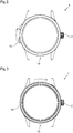
- la
figure 1 est une vue de dessus d'un premier mode de réalisation d'une montre chronographe selon l'invention; - la
figure 2 est une vue de dessus du premier mode de réalisation d'une montre chronographe selon l'invention, l'organe d'actionnement étant dans sa position initiale neutre, la position maximale de remontage étant représentée en traitillé; et - la
figure 3 est une vue de dessus d'un deuxième mode de réalisation d'une montre chronographe selon l'invention. - En référence à la
figure 1 , la présente invention concerne une montre chronographe 1 comprenant comme premier mouvement agencé pour produire une première fonction de mesure d'un temps et l'afficher sur un cadran, un mouvement de chronographe et comme deuxième mouvement agencé pour produire une deuxième fonction de mesure d'un temps et l'afficher sur un cadran, un mouvement horloger indiquant le temps courant. - Dans la présente invention, un mouvement agencé pour produire une fonction de mesure d'un temps et l'afficher sur un cadran est un mouvement agencé pour mesurer l'intervalle de temps qui s'est écoulé entre minuit et l'heure du moment pour indiquant le temps courant ou pour mesurer l'intervalle de temps écoulé entre un départ et un arrêt lors d'un événement et connaitre la durée d'exécution dudit événement. Ces types de mouvements nécessitent une mesure précise du temps, de sorte que l'organe de régulation est un système oscillant, par exemple un balancier-spiral ou un oscillateur à guidage flexible. De ce fait, sont exclus de l'invention les mécanismes de sonneries. En effet, les mécanismes de sonnerie n'effectuant pas de mesure d'intervalle de temps nécessitant une mesure précise, utilisent seulement des régulateurs de vitesse.
- Dans la présente description, le terme « chronographe » doit être considéré au sens large du terme, c'est-à-dire comme comprenant tous les éléments ou composants nécessaires agencés pour produire tous les types de comptage/décompte de temps et fraction de temps, tel que, par exemple, un chrono standard, un compte à rebours, un chrono régate, à rattrapante, à foudroyante et fraction de seconde.
- Le mouvement de chronographe comprend un barillet de chronographe 4 dédié au fonctionnement dudit mouvement de chronographe, un système réglant 6 comprenant un mécanisme d'échappement 8 et un oscillateur 10, et un rouage 12 reliant le barillet de chronographe 4 au système réglant 6.
- Le mouvement horloger indiquant le temps courant est muni de sa propre source d'énergie, telle qu'un barillet (non représenté), de son propre système réglant 7 comprenant un mécanisme d'échappement 9 et un oscillateur 11, et de son propre rouage de finissage 13 reliant le barillet au système réglant 7. Ce mouvement horloger indiquant le temps courant comprend également ici son propre mécanisme de remontage pourvu de son propre organe d'actionnement, tel qu'une tige de remontoir terminée par une couronne de remontoir 2, et positionnée à 3h, de manière standard. Un tel mouvement horloger pour indiquer le temps courant est standard. Les composants d'un tel mouvement horloger sont connus de l'homme du métier et ne nécessitent pas de description plus détaillée. Toutefois, il est précisé ici que le barillet propre au mouvement indiquant le temps courant est superposé au barillet de chronographe 4.
- Il est possible de prévoir un seul système réglant commun au mouvement indiquant le temps courant et au chronographe, en étant agencé de manière appropriée pour coopérer d'une part avec le barillet du mouvement indiquant le temps courant et d'autre part avec le barillet de chronographe 4.
- De préférence, la montre chronographe 1 comprend comme premier système réglant, le système réglant 6 comprenant, comme premier mécanisme d'échappement, le mécanisme d'échappement 8, et comme premier oscillateur réglant le mouvement de chronographe, l'oscillateur 10, et comme second système réglant, le système réglant 7, comprenant comme second mécanisme d'échappement, le mécanisme d'échappement 9, et comme second oscillateur réglant le mouvement horloger indiquant le temps courant, l'oscillateur 11 de type balancier à ressort spiral traditionnel.
- De préférence, le premier oscillateur 10 réglant le mouvement de chronographe est un oscillateur à guidage flexible. Un tel oscillateur à guidage flexible est décrit par exemple dans la publication
EP 3 502 784 de la demanderesse. D'une manière avantageuse, les premier et second oscillateurs ont des fréquences différentes, le premier oscillateur dédié au mouvement de chronographe ayant une fréquence supérieure à celle du second oscillateur dédié au mouvement horloger indiquant le temps courant. - Plus particulièrement, le second oscillateur peut avoir une basse fréquence, inférieure à 10 Hz, et de préférence inférieure ou égale à 5Hz, et le premier oscillateur 10 dédié au mouvement de chronographe peut avoir une fréquence élevée, supérieure à 10 Hz, de préférence supérieure ou égale à 20 Hz, et plus préférentiellement supérieure ou égale à 50 Hz.
- Le rouage 12 est dédié au mouvement de chronographe et désigne de manière globale le rouage de finissage reliant le barillet de chronographe 4 au mécanisme d'échappement 8 définissant une base de temps propre au chronographe et le rouage de chronographe comprenant notamment des compteurs de chronographe et de minutes (non représentés) entrainés par le rouage de finissage et agencés pour entraîner en rotation des organes indicateurs des temps mesurés (non représentés).
- Le mouvement de chronographe comprend également un mécanisme de chronographe (non représenté) gérant les fonctions chronographe marche/arrêt/remise à zéro, agencé pour être entrainé par le rouage 12. Le mécanisme de chronographe peut être de type à roue à colonnes, commandée de manière conventionnelle à partir d'un poussoir (non représenté). Le mécanisme de chronographe comprend également des organes de remise à zéro, tels que des poussoirs, permettant de réinitialiser les positions des organes indicateurs des temps mesurés après une mesure.
- Un tel mécanisme de chronographe est bien connu de l'homme du métier.
- Le mouvement de chronographe comprend également un mécanisme de remontage 14 du barillet de chronographe 4 agencé pour être indépendant du fonctionnement du chronographe. Cela signifie qu'il est possible de remonter le barillet de chronographe 4 sans activer une des fonctions du chronographe, et notamment sans le remettre à zéro ou sans le déclencher, et que le remontage du barillet de chronographe 4 est également possible pendant le fonctionnement du chronographe, sans influencer les mesures. Ce remontage autonome du barillet de chronographe 4 est lié à la construction du barillet 4 et à l'utilisation de commandes des fonctions chronographe différentes et indépendantes de la commande du mécanisme de remontage du barillet de chronographe 4.
- Le mécanisme de remontage 14 du barillet de chronographe 4 comprend un seul organe d'actionnement 16, apparaissant à l'extérieur de la boite de montre 18, actionnable par un utilisateur, et dédié à la fonction de remontage uniquement du barillet de chronographe 4. Ainsi, l'organe d'actionnement 16 est différent et indépendant de la couronne de remontoir 2 du mouvement horloger indiquant le temps courant standard, qui permet son remontage et sa mise à l'heure par rotation de ladite couronne de remontoir, ainsi que des commandes des fonctions chronographe.
- Conformément à l'invention, l'organe d'actionnement 16 est agencé pour glisser sur un élément de la boite de montre 18 et se déplacer en rotation dans un plan transversal de la boite de montre 18, par rapport au centre de la boite de montre 18, c'est-à-dire dans un plan «horizontal» parallèle au cadran ou perpendiculaire à un axe central de la boite 18 autour duquel ladite boite 18 présente une symétrie générale de révolution, d'un angle inférieur à 360°, de préférence inférieur ou égal à 180°, et plus préférentiellement inférieur ou égal à 90°, à chaque actionnement, entre une position initiale neutre et une position maximale de remontage pour remonter au moins partiellement le barillet de chronographe 4.
- En outre, le mécanisme de remontage de chronographe comprend un rouage de remontage multiplicatif 20 reliant l'organe d'actionnement 16 au barillet de chronographe 4, ledit rouage de remontage 20 étant agencé pour obtenir le remontage maximal du barillet de chronographe 4 en au moins un actionnement de l'organe d'actionnement 16, et en au plus dix, de préférence au plus cinq actionnements successifs dudit organe d'actionnement 16.
- D'une manière avantageuse, l'organe d'actionnement 16 est agencé pour se déplacer en rotation par rapport au centre de la boite de montre 18 d'un angle inférieur ou égal à 120°, de préférence inférieur ou égal à 90°, et plus préférentiellement inférieur ou égal à 45°, à chaque actionnement, entre sa position initiale neutre et sa position maximale de remontage, et le rouage de remontage multiplicatif 20 est agencé pour obtenir le remontage maximal du barillet de chronographe 4 en moins de cinq actionnements successifs de l'organe d'actionnement 16, et de préférence en moins de trois actionnements successifs, voire deux ou un seul actionnement dudit organe d'actionnement 16.
- D'une manière particulièrement préférée, l'organe d'actionnement 16 est agencé pour se déplacer en rotation par rapport au centre de la boite de montre 18 d'un angle supérieur ou égal à 30° et inférieur ou égal à 45°, à chaque actionnement, entre sa position initiale neutre et sa position maximale de remontage, et le rouage de remontage multiplicatif 20 est agencé pour obtenir le remontage maximal du barillet de chronographe 4 en un seul actionnement dudit organe d'actionnement 16.
- L'organe d'actionnement 16 peut être un verrou ou une targette, positionné par exemple entre 8h et 9h, comme représenté sur les
figures 1 et2 . Le verrou peut être agencé pour se déplacer en rotation par rapport au centre de la boite de montre 18, par exemple dans le sens horaire comme représenté sur lafigure 2 , d'un angle de préférence supérieur ou égal à 30° et inférieur ou égal à 90°, et de préférence inférieur ou égal à 45°, à chaque actionnement, entre sa position initiale neutre et sa position maximale de remontage, représentée par le verrou 16 en traitillé. Le verrou comprend une tête 16a extérieure à la boite de montre 18, agencée pour glisser sur la carrure 22. A cet effet, une glissière est aménagée dans la surface extérieure de ladite carrure 22, la tête 16a du verrou étant agencée pour être guidée par la glissière de façon à pouvoir coulisser sur la surface extérieure de la boîte de montre 18. La tête 16a du verrou est prolongée par une crémaillère 16b logée à l'intérieur de la boite de montre 18 et engrenant avec le premier mobile 24 du rouage de remontage 20. - L'organe d'actionnement 16 peut être également l'un des éléments de la boite de montre 18, tel qu'une lunette, le fond ou une partie mobile de la carrure, ladite carrure étant alors en deux parties, ledit élément de boite de montre étant agencé pour glisser sur l'un des autres éléments de la boite de montre 18 et se déplacer en rotation à chaque actionnement selon la définition de l'invention.
- Notamment, l'organe d'actionnement 16 peut être une lunette agencée pour être montée mobile en rotation sur la boite de montre 18, par exemple dans le sens horaire, comme représenté sur la
figure 3 . La lunette, ou l'un des autres éléments de la boite de montre, peut être agencée pour se déplacer en rotation par rapport au centre de la montre d'un angle supérieur ou égal à 30° et inférieur à 360°, et de préférence inférieur ou égal à 180°, et plus préférentiellement inférieur ou égal à 90°, voire 45°, à chaque actionnement, entre sa position initiale neutre et sa position maximale de remontage. La lunette comprend une denture interne (non représentée) engrenant avec le premier mobile 24 du rouage de remontage 20. - Le rouage de remontage multiplicatif 20 comprend différents mobiles en fonction de l'énergie à fournir pour remonter le barillet de chronographe 4. L'homme du métier sait dimensionner la crémaillère 16b et les mobiles du rouage de remontage 20 afin de pouvoir obtenir le rapport multiplicatif recherché pour obtenir le remontage complet du barillet de chronographe 4 avec le nombre d'actionnements et l'angle de rotation par actionnement souhaités de l'organe d'actionnement 16.
- Le barillet de chronographe 4 comprend un tambour 26 agencé pour coopérer avec le rouage 12, et présentant à cet effet à sa périphérie extérieure une denture engrenant avec un pignon 28a d'une roue 28 du rouage 12. Le barillet de chronographe 4 comprend également un arbre de barillet 30 autour duquel le tambour 26 est monté mobile en rotation, ainsi qu'un ressort (non représenté) logé dans le tambour 26. L'extrémité extérieure du ressort est couplée à la surface interne de la paroi du tambour 26 d'une manière traditionnelle, par exemple à l'aide d'une bride, qui peut être glissante pour éviter une surtension du ressort en cas de remontage excessif. L'extrémité intérieure du ressort est couplée à un crochet prévu sur une bonde de l'arbre de barillet 30 d'une manière traditionnelle également.
- De plus, le mécanisme de remontage du barillet de chronographe 4 comprend une roue d'armage 32 coopérant avec le dernier mobile 34 du rouage de remontage multiplicatif 20, coaxiale et solidaire en rotation à l'arbre de barillet 30, la roue d'armage 32 et l'arbre de barillet 30 étant agencés pour être entrainés en rotation lorsque l'organe d'actionnement 16 est actionné pour armer le ressort et remonter le barillet de chronographe 4, indépendamment du fonctionnement du chronographe.
- Avantageusement, la roue d'armage 32 est de type rochet et est pourvue d'un cliquet 36 empêchant le désarmage du ressort par l'arbre de barillet 30. Ainsi, le ressort est obligé de se désarmer par le tambour 26 en délivrant l'énergie au rouage 12, la roue d'armage 32 et l'arbre de barillet 30 étant immobilisés lors du désarmage du ressort lorsque le chronographe fonctionne. Cette construction standard d'un barillet appliqué au barillet de chronographe 4 permet le remontage du barillet de chronographe 4 indépendamment du chronométrage, avant ou pendant l'utilisation du chronographe. Plus particulièrement, le chronographe peut être déclenché indépendamment de son remontage, de sorte que la mesure du temps est précise, le départ du chronographe n'étant pas perturbé par le remontage de son barillet. Le remontage du barillet est possible avant d'utiliser le chronographe, de manière à garantir son bon fonctionnement avant son déclenchement. De plus, le remontage du barillet est également possible pendant le chronométrage, afin d'assurer cette fonction même en cours d'utilisation. Cette construction du barillet de chronographe 4 permet également d'éviter le désarmage du ressort lorsque le chronographe n'est pas déclenché et de conserver l'énergie du barillet de chronographe dans l'attente du prochain chronométrage.
- La position maximale de remontage de l'organe d'actionnement 16 correspond à la position à partir de laquelle l'organe d'actionnement 16, lâché par l'utilisateur, revient à sa position initiale neutre sans agir sur le barillet de chronographe 4. A cet effet, l'organe d'actionnement 16 comprend un ressort de rappel (non représenté) agencé pour le rappeler dans sa position initiale neutre, et le mécanisme de remontage 14 du barillet de chronographe 4 comprend, entre l'organe d'actionnement 16 et le barillet de chronographe 4, un dispositif d'entrainement unidirectionnel 38 agencé pour lier cinématiquement l'organe d'actionnement 16 au barillet de chronographe 4 lors de son déplacement de sa position initiale neutre à sa position maximale de remontage et pour débrayer l'organe d'actionnement 16 du barillet de chronographe 4 lors d'un retour dudit organe d'actionnement 16 de sa position maximale de remontage à sa position initiale neutre.
- Ce dispositif d'entrainement unidirectionnel 38 peut comprendre par exemple un mobile d'embrayage comprenant un pignon 40 et une roue 42 pivotant l'un par rapport à l'autre, une première pièce d'entrainement solidaire angulairement du pignon 40 et comportant des cliquets élastiques, et une seconde pièce d'entrainement solidaire angulairement de la roue 42 et comportant une denture interne en dent de loup. Un tel dispositif d'entrainement unidirectionnel est décrit par exemple dans le brevet
EP 2 392 975 de la demanderesse. Les éléments du dispositif d'entrainement unidirectionnel 38 sont agencés pour que, selon l'exemple représenté, lors du remontage du barillet de chronographe 4 par le déplacement en rotation de l'organe d'actionnement 16 dans le sens horaire, la rotation de la roue 42 dans le sens antihoraire provoque l'entrée en contact des extrémités des cliquets élastiques avec la denture interne en dent de loup provoquant l'entrainement du pignon 40 par la roue 42, de sorte que le dispositif d'entrainement unidirectionnel 38 est embrayé et peut entrainer le mobile suivant 44 du rouage de remontage 20 engrenant avec la roue d'armage 32 pour armer le ressort et remonter le barillet de chronographe 4. Lorsque l'organe d'actionnement 16 est rappelé dans sa position initiale par son ressort de rappel, son déplacement en rotation dans le sens antihoraire entraine la rotation de la roue 42 dans le sens horaire de sorte que les cliquets ne touchent plus les dents de la denture interne en dent de loup. Le dispositif d'entrainement unidirectionnel 38 est alors débrayé, et l'organe d'actionnement 16 est dissocié de la roue d'armage 32, de sorte que le retour en position initiale de l'organe d'actionnement 16 est sans effet sur le barillet de chronographe 4. Il est bien évident que tout autre dispositif d'entrainement unidirectionnel approprié peut être utilisé. - La présente invention permet de remonter rapidement le barillet dédié à un chronographe, d'une manière ergonomique et brève, afin de ne pas gêner l'utilisateur, et d'offrir la possibilité d'un remontage du barillet de chronographe en cours d'utilisation pour assurer la fonction de chronographe, ainsi qu'un déclenchement séparé du chronographe pour assurer la précision des temps mesurés.
- En outre, l'utilisation d'une source d'énergie, d'un mécanisme comprenant un rouage spécifique, et d'un organe réglant dédiés au chronographe permet de ne jamais perturber le mouvement indiquant le temps courant.
- La présente invention peut s'appliquer à tout mouvement agencé pour produire une fonction de mesure d'un temps. Par exemple, dans une autre variante non représentée, seul le barillet d'un mouvement horloger indiquant le temps courant peut être remonté par un mécanisme de remontage comprenant un organe d'actionnement selon l'invention. Dans ce cas, la tige de remontoir liée audit mouvement horloger n'a plus de fonction de remontage mais seulement de mise à l'heure. L'homme du métier sait dimensionner l'organe d'actionnement et les mobiles du rouage de remontage reliant ledit organe d'actionnement au barillet du mouvement indiquant le temps courant afin de pouvoir obtenir le rapport multiplicatif recherché pour obtenir le remontage complet du barillet du mouvement indiquant le temps courant avec le nombre d'actionnements et l'angle de rotation par actionnement souhaités de l'organe d'actionnement 16 conformément à l'invention.
- Dans cette variante, l'invention permet de remonter rapidement le barillet d'un mouvement horloger standard indiquant le temps courant d'une manière ergonomique et brève.
- Dans une autre variante non représentée dans laquelle la montre comprend un mouvement indiquant le temps courant et un mouvement de chronographe comme décrit dans l'exemple ci-dessus, l'organe d'actionnement du mouvement indiquant le temps courant n'est plus la tige de remontoir mais est confondu avec l'organe d'actionnement du mécanisme de remontage du mouvement de chronographe. Dans ce cas, le mécanisme de remontage du mouvement indiquant le temps courant comprend un deuxième rouage de remontage multiplicatif reliant l'organe d'actionnement 16 au barillet du mouvement indiquant le temps courant, ledit deuxième rouage de remontage multiplicatif étant agencé pour obtenir le remontage maximal du barillet du mouvement indiquant le temps courant en au moins un actionnement de l'organe d'actionnement 16, et en au plus dix, de préférence au plus cinq actionnements successifs dudit organe d'actionnement 16. A cet effet, par exemple la crémaillère 16b est configurée pour engrener avec le premier mobile de chacun des rouages de remontage multiplicatifs en même temps. L'homme du métier sait dimensionner l'organe d'actionnement et les mobiles de chacun des rouages de remontage multiplicatifs reliant ledit organe d'actionnement au barillet de chronographe et au barillet du mouvement indiquant le temps courant afin de pouvoir obtenir les rapports multiplicatifs recherchés pour obtenir le remontage complet du barillet de chronographe et du barillet du mouvement indiquant le temps courant avec le nombre d'actionnements et l'angle de rotation par actionnement souhaités de l'organe d'actionnement 16 conformément à l'invention.
- Dans cette variante, l'invention permet de remonter rapidement à la fois le barillet de chronographe et le barillet d'un mouvement horloger standard indiquant le temps courant d'une manière ergonomique et brève.
Claims (13)
- Montre (1) comprenant une boite de montre (18) renfermant au moins un premier mouvement agencé pour produire une première fonction de mesure d'un temps, ledit premier mouvement comprenant un premier barillet (4) agencé pour alimenter en énergie au moins ledit premier mouvement, un système réglant (6) comprenant un mécanisme d'échappement (8) et un oscillateur (10), un rouage (12) reliant le premier barillet (4) au système réglant (6), ainsi qu'un premier mécanisme de remontage (14) du premier barillet (4) comprenant un premier organe d'actionnement (16) actionnable par un utilisateur, ledit premier mécanisme de remontage (14) du premier barillet (4) étant agencé pour que le remontage dudit premier barillet (4) soit indépendant du fonctionnement de la première fonction du premier mouvement,
caractérisée en ce que ledit premier organe d'actionnement (16) est agencé pour glisser sur un élément de la boite de montre (18) et se déplacer en rotation dans un plan transversal de la boite de montre (18), à chaque actionnement, d'un angle inférieur à 360°, de préférence inférieur ou égal à 180°, et plus préférentiellement inférieur ou égal à 90°, entre une position initiale neutre et une position maximale de remontage pour remonter au moins partiellement le premier barillet (4), et en ce que le premier mécanisme de remontage (14) comprend un premier rouage de remontage multiplicatif (20) reliant le premier organe d'actionnement (16) au premier barillet (4), ledit premier rouage de remontage (20) étant agencé pour obtenir le remontage maximal du premier barillet (4) en au moins un actionnement du premier organe d'actionnement (16), et en au plus dix, de préférence au plus cinq actionnements dudit premier organe d'actionnement (16). - Montre (1) selon la revendication 1, caractérisée en ce que le premier organe d'actionnement (16) est agencé pour se déplacer en rotation d'un angle inférieur ou égal à 120°, de préférence inférieur ou égal à 90°, et plus préférentiellement inférieur ou égal à 45°, à chaque actionnement, entre sa position initiale neutre et sa position maximale de remontage, et en ce que le premier rouage de remontage multiplicatif (20) est agencé pour obtenir le remontage maximal du premier barillet (4) en moins de cinq actionnements du premier organe d'actionnement (16), et de préférence en moins de trois actionnements dudit premier organe d'actionnement (16).
- Montre (1) selon l'une des revendications précédentes, caractérisée en ce que le premier organe d'actionnement (16) est agencé pour se déplacer en rotation d'un angle inférieur ou égal à 45°, à chaque actionnement, entre sa position initiale neutre et sa position maximale de remontage, et en ce que le premier rouage de remontage multiplicatif (20) est agencé pour obtenir le remontage maximal du premier barillet (4) en un seul actionnement dudit premier organe d'actionnement (16).
- Montre (1) selon l'une des revendications précédentes, caractérisé en ce que le premier barillet (4) comprend un tambour (26) agencé pour coopérer avec le rouage (12), un arbre de barillet (30) autour duquel le tambour (26) est monté mobile en rotation, un ressort logé dans le tambour (26) et dont une extrémité extérieure est couplée au tambour (26) et une extrémité intérieure est couplée à l'arbre de barillet (30), et en ce que le premier mécanisme de remontage (14) du premier barillet (4) comprend une roue d'armage (32) coopérant avec le premier rouage de remontage multiplicatif (20), coaxiale et solidaire en rotation à l'arbre de barillet (30), la roue d'armage (32) et l'arbre de barillet (30) étant agencés pour être entrainés en rotation lorsque le premier organe d'actionnement (16) est actionné pour armer ledit ressort, indépendamment du fonctionnement de la première fonction du premier mouvement.
- Montre (1) selon la revendication 4, caractérisée en ce que la roue d'armage (32) est pourvue d'un cliquet (36) empêchant le désarmage du ressort par l'arbre de barillet (30).
- Montre (1) selon l'une des revendications précédentes, caractérisée en ce que le premier mécanisme de remontage (14) du premier barillet (4) comprend, entre le premier organe d'actionnement (16) et ledit premier barillet (4), un dispositif d'entrainement unidirectionnel (38) agencé pour lier cinématiquement le premier organe d'actionnement (16) au premier barillet (4) lors de son déplacement de sa position initiale neutre à sa position maximale de remontage et pour débrayer le premier organe d'actionnement (16) du premier barillet (4) lors d'un retour dudit premier organe d'actionnement (16) de sa position maximale de remontage à sa position initiale neutre.
- Montre (1) selon l'une des revendications précédentes, caractérisé en ce que le premier organe d'actionnement (16) est un verrou agencé pour coulisser sur la surface extérieure de la boite de montre (18) ou l'un des éléments de la boite de montre (18) agencé pour glisser sur l'un des autres éléments de la boite de montre (18).
- Montre (1) selon l'une des revendications précédentes, caractérisée en ce que le premier mouvement est un mouvement de chronographe, le premier barillet (4) étant un barillet de chronographe dédié audit mouvement de chronographe, et en ce que la boite de montre renferme un deuxième mouvement horloger indiquant le temps courant et comprenant un deuxième barillet agencé pour alimenter en énergie ledit deuxième mouvement ainsi qu'un deuxième mécanisme de remontage du deuxième barillet comprenant un deuxième organe d'actionnement actionnable par un utilisateur.
- Montre selon la revendication 8, caractérisée en ce que le deuxième organe d'actionnement est une tige de remontoir (2).
- Montre (1) selon la revendication 8, caractérisée en ce que le premier organe d'actionnement et le deuxième organe d'actionnement sont confondus, le deuxième mécanisme de remontage comprenant un deuxième rouage de remontage multiplicatif (20) reliant le premier organe d'actionnement (16) au deuxième barillet, ledit deuxième rouage de remontage étant agencé pour obtenir le remontage maximal du deuxième barillet en au moins un actionnement du premier organe d'actionnement (16), et en au plus dix, de préférence au plus cinq actionnements dudit premier organe d'actionnement (16).
- Montre (1) selon l'une des revendications 8 à 10, caractérisée en ce qu'elle comprend un premier oscillateur (10) réglant le premier mouvement de chronographe et un second oscillateur (11) réglant le deuxième mouvement indiquant le temps courant.
- Montre (1) selon la revendication 11, caractérisée en ce que le premier oscillateur (10) est un oscillateur à guidage flexible.
- Montre (1) selon l'une des revendications 8 à 12, caractérisée en ce que les premier et deuxième barillets sont superposés.
Priority Applications (1)
| Application Number | Priority Date | Filing Date | Title |
|---|---|---|---|
| EP20155930.9A EP3862818B1 (fr) | 2020-02-06 | 2020-02-06 | Montre comprenant un mécanisme de remontage |
Applications Claiming Priority (1)
| Application Number | Priority Date | Filing Date | Title |
|---|---|---|---|
| EP20155930.9A EP3862818B1 (fr) | 2020-02-06 | 2020-02-06 | Montre comprenant un mécanisme de remontage |
Publications (2)
| Publication Number | Publication Date |
|---|---|
| EP3862818A1 true EP3862818A1 (fr) | 2021-08-11 |
| EP3862818B1 EP3862818B1 (fr) | 2026-05-13 |
Family
ID=69526098
Family Applications (1)
| Application Number | Title | Priority Date | Filing Date |
|---|---|---|---|
| EP20155930.9A Active EP3862818B1 (fr) | 2020-02-06 | 2020-02-06 | Montre comprenant un mécanisme de remontage |
Country Status (1)
| Country | Link |
|---|---|
| EP (1) | EP3862818B1 (fr) |
Citations (8)
| Publication number | Priority date | Publication date | Assignee | Title |
|---|---|---|---|---|
| US550182A (en) * | 1895-11-19 | lecoultre-piguet | ||
| CH118493A (fr) | 1926-01-28 | 1927-01-03 | Louis Schwab | Montre, comportant un mécanisme de remontage et de mise à l'heure commandé par la lunette de glace. |
| CH701670A2 (fr) * | 2009-08-17 | 2011-02-28 | Gaetan Willemin | Méchanisme de remontage d'une montre par une corne mobile. |
| EP2392975A2 (fr) | 2010-06-03 | 2011-12-07 | Patek Philippe SA Genève | Organe mobile à embrayage unidirectionnel |
| WO2016001740A2 (fr) * | 2014-07-03 | 2016-01-07 | Preciflex Sa | Mécanismes d'horlogerie pour mouvement à commande unique dédié à la double accumulation et la transmission de puissance |
| EP3059642A1 (fr) | 2015-02-23 | 2016-08-24 | Montres Breguet S.A. | Mécanisme de chronographe |
| CH711239A1 (de) * | 2015-06-23 | 2016-12-30 | Richemont Int Sa | Steuerungsvorrichtung für Uhren. |
| EP3502784A1 (fr) | 2017-12-22 | 2019-06-26 | Patek Philippe SA Genève | Resonateur horloger a guidage flexible |
-
2020
- 2020-02-06 EP EP20155930.9A patent/EP3862818B1/fr active Active
Patent Citations (8)
| Publication number | Priority date | Publication date | Assignee | Title |
|---|---|---|---|---|
| US550182A (en) * | 1895-11-19 | lecoultre-piguet | ||
| CH118493A (fr) | 1926-01-28 | 1927-01-03 | Louis Schwab | Montre, comportant un mécanisme de remontage et de mise à l'heure commandé par la lunette de glace. |
| CH701670A2 (fr) * | 2009-08-17 | 2011-02-28 | Gaetan Willemin | Méchanisme de remontage d'une montre par une corne mobile. |
| EP2392975A2 (fr) | 2010-06-03 | 2011-12-07 | Patek Philippe SA Genève | Organe mobile à embrayage unidirectionnel |
| WO2016001740A2 (fr) * | 2014-07-03 | 2016-01-07 | Preciflex Sa | Mécanismes d'horlogerie pour mouvement à commande unique dédié à la double accumulation et la transmission de puissance |
| EP3059642A1 (fr) | 2015-02-23 | 2016-08-24 | Montres Breguet S.A. | Mécanisme de chronographe |
| CH711239A1 (de) * | 2015-06-23 | 2016-12-30 | Richemont Int Sa | Steuerungsvorrichtung für Uhren. |
| EP3502784A1 (fr) | 2017-12-22 | 2019-06-26 | Patek Philippe SA Genève | Resonateur horloger a guidage flexible |
Also Published As
| Publication number | Publication date |
|---|---|
| EP3862818B1 (fr) | 2026-05-13 |
Similar Documents
| Publication | Publication Date | Title |
|---|---|---|
| EP1470452B1 (fr) | Dispositif comportant un mouvement horaire et un module chronographe | |
| EP1777598B1 (fr) | Pièce d'horlogerie munie d'un mécanisme de mesure de durées prédéterminées réglables | |
| EP1402322B1 (fr) | Piece d'horlogerie comportant un dispositif de sonnerie | |
| EP2073076B1 (fr) | Mécanisme de commande d'un réveil | |
| EP2367080B1 (fr) | Dispositif de commande et de réglage d'un mouvement horloger | |
| EP2498148A1 (fr) | Mécanisme de sécurité contre des manipulations intempestives de commande d'une répétition minutes | |
| EP3435176B1 (fr) | Lissage de couple pour pièce d'horlogerie avec mécanisme de sonnerie, notamment avec mécanisme de sonnerie | |
| EP2508953A2 (fr) | Mécanisme de chronographe | |
| CH716841A1 (fr) | Mouvement d'horlogerie à chronographe. | |
| WO2002077723A1 (fr) | Piece d'horlogerie comportant un mecanisme pour l'enclenchement d'une fonction horaire et l'armage simultane d'un ressort de barillet | |
| EP4320487B1 (fr) | Pièce d'horlogerie à répétition et alarme | |
| CH697433B1 (fr) | Pièce d'horlogerie avec mécanisme chronographe. | |
| EP3862818B1 (fr) | Montre comprenant un mécanisme de remontage | |
| EP4189493B1 (fr) | Ensemble sympathique d'horlogerie | |
| EP2367076B1 (fr) | Dispositif d'alarme réglable 30 jours à l'avance | |
| EP4071562B1 (fr) | Mécanisme de sonnerie et pièce d'horlogerie le comprenant | |
| EP3995906B1 (fr) | Mécanisme d'affichage numérique pour chronographe à rattrapante et chronographe comportant un tel mécanisme | |
| EP4071561B1 (fr) | Pièce d'horlogerie à répétition | |
| CH702846A2 (fr) | Dispositif de commande et de réglage d'un mouvement horloger. | |
| CH719555B1 (fr) | Mécanisme de chronographe avec sonnerie | |
| CH682201B5 (fr) | Mouvement de chronographe automatique à rattrapante. | |
| EP4254076A1 (fr) | Dispositif horloger de comptage | |
| CH714530A2 (fr) | Mécanisme de répétition chronographe avec sécurité. | |
| EP2254007B1 (fr) | Dispositif d'affichage de la réserve de marche pour une pièce d'horlogerie | |
| FR3023934A1 (fr) | Mecanisme d'horlogerie |
Legal Events
| Date | Code | Title | Description |
|---|---|---|---|
| PUAI | Public reference made under article 153(3) epc to a published international application that has entered the european phase |
Free format text: ORIGINAL CODE: 0009012 |
|
| STAA | Information on the status of an ep patent application or granted ep patent |
Free format text: STATUS: THE APPLICATION HAS BEEN PUBLISHED |
|
| AK | Designated contracting states |
Kind code of ref document: A1 Designated state(s): AL AT BE BG CH CY CZ DE DK EE ES FI FR GB GR HR HU IE IS IT LI LT LU LV MC MK MT NL NO PL PT RO RS SE SI SK SM TR |
|
| STAA | Information on the status of an ep patent application or granted ep patent |
Free format text: STATUS: REQUEST FOR EXAMINATION WAS MADE |
|
| 17P | Request for examination filed |
Effective date: 20211228 |
|
| RBV | Designated contracting states (corrected) |
Designated state(s): AL AT BE BG CH CY CZ DE DK EE ES FI FR GB GR HR HU IE IS IT LI LT LU LV MC MK MT NL NO PL PT RO RS SE SI SK SM TR |
|
| RIN1 | Information on inventor provided before grant (corrected) |
Inventor name: OES, STEPHANE Inventor name: KRUETTLI, ANTHONY |
|
| P01 | Opt-out of the competence of the unified patent court (upc) registered |
Effective date: 20230521 |
|
| STAA | Information on the status of an ep patent application or granted ep patent |
Free format text: STATUS: EXAMINATION IS IN PROGRESS |
|
| 17Q | First examination report despatched |
Effective date: 20231025 |
|
| GRAP | Despatch of communication of intention to grant a patent |
Free format text: ORIGINAL CODE: EPIDOSNIGR1 |
|
| STAA | Information on the status of an ep patent application or granted ep patent |
Free format text: STATUS: GRANT OF PATENT IS INTENDED |
|
| INTG | Intention to grant announced |
Effective date: 20251205 |
|
| GRAS | Grant fee paid |
Free format text: ORIGINAL CODE: EPIDOSNIGR3 |
|
| GRAA | (expected) grant |
Free format text: ORIGINAL CODE: 0009210 |
|
| STAA | Information on the status of an ep patent application or granted ep patent |
Free format text: STATUS: THE PATENT HAS BEEN GRANTED |
|
| AK | Designated contracting states |
Kind code of ref document: B1 Designated state(s): AL AT BE BG CH CY CZ DE DK EE ES FI FR GB GR HR HU IE IS IT LI LT LU LV MC MK MT NL NO PL PT RO RS SE SI SK SM TR |
|
| REG | Reference to a national code |
Ref country code: CH Ref legal event code: F10 Free format text: ST27 STATUS EVENT CODE: U-0-0-F10-F00 (AS PROVIDED BY THE NATIONAL OFFICE) Effective date: 20260513 Ref country code: GB Ref legal event code: FG4D Free format text: NOT ENGLISH |
|
| REG | Reference to a national code |
Ref country code: DE Ref legal event code: R096 Ref document number: 602020071993 Country of ref document: DE Ref country code: CH Ref legal event code: R17 Free format text: ST27 STATUS EVENT CODE: U-0-0-R10-R17 (AS PROVIDED BY THE NATIONAL OFFICE) Effective date: 20260603 Ref country code: IE Ref legal event code: FG4D Free format text: LANGUAGE OF EP DOCUMENT: FRENCH |