EP3862734A1 - An item and a method for sensing and displaying temperature thereof - Google Patents
An item and a method for sensing and displaying temperature thereof Download PDFInfo
- Publication number
- EP3862734A1 EP3862734A1 EP20213598.4A EP20213598A EP3862734A1 EP 3862734 A1 EP3862734 A1 EP 3862734A1 EP 20213598 A EP20213598 A EP 20213598A EP 3862734 A1 EP3862734 A1 EP 3862734A1
- Authority
- EP
- European Patent Office
- Prior art keywords
- item
- temperature
- sensor
- temperature value
- indication
- Prior art date
- Legal status (The legal status is an assumption and is not a legal conclusion. Google has not performed a legal analysis and makes no representation as to the accuracy of the status listed.)
- Granted
Links
Images



Classifications
-
- G—PHYSICS
- G01—MEASURING; TESTING
- G01K—MEASURING TEMPERATURE; MEASURING QUANTITY OF HEAT; THERMALLY-SENSITIVE ELEMENTS NOT OTHERWISE PROVIDED FOR
- G01K1/00—Details of thermometers not specially adapted for particular types of thermometer
- G01K1/14—Supports; Fastening devices; Arrangements for mounting thermometers in particular locations
-
- G—PHYSICS
- G01—MEASURING; TESTING
- G01K—MEASURING TEMPERATURE; MEASURING QUANTITY OF HEAT; THERMALLY-SENSITIVE ELEMENTS NOT OTHERWISE PROVIDED FOR
- G01K1/00—Details of thermometers not specially adapted for particular types of thermometer
- G01K1/02—Means for indicating or recording specially adapted for thermometers
-
- G—PHYSICS
- G01—MEASURING; TESTING
- G01K—MEASURING TEMPERATURE; MEASURING QUANTITY OF HEAT; THERMALLY-SENSITIVE ELEMENTS NOT OTHERWISE PROVIDED FOR
- G01K3/00—Thermometers giving results other than momentary value of temperature
- G01K3/005—Circuits arrangements for indicating a predetermined temperature
-
- G—PHYSICS
- G01—MEASURING; TESTING
- G01K—MEASURING TEMPERATURE; MEASURING QUANTITY OF HEAT; THERMALLY-SENSITIVE ELEMENTS NOT OTHERWISE PROVIDED FOR
- G01K7/00—Measuring temperature based on the use of electric or magnetic elements directly sensitive to heat ; Power supply therefor, e.g. using thermoelectric elements
- G01K7/16—Measuring temperature based on the use of electric or magnetic elements directly sensitive to heat ; Power supply therefor, e.g. using thermoelectric elements using resistive elements
- G01K7/18—Measuring temperature based on the use of electric or magnetic elements directly sensitive to heat ; Power supply therefor, e.g. using thermoelectric elements using resistive elements the element being a linear resistance, e.g. platinum resistance thermometer
- G01K7/183—Measuring temperature based on the use of electric or magnetic elements directly sensitive to heat ; Power supply therefor, e.g. using thermoelectric elements using resistive elements the element being a linear resistance, e.g. platinum resistance thermometer characterised by the use of the resistive element
Definitions
- the present invention generally relates to items. More particularly, the invention relates to sensing temperature inside an item.
- the goods may be in the form of one or more items having contents therein. Some contents may be sensitive to environmental factors such as temperature, humidity, pressure etc. Manufacturers of items with sensitive content may define a specific threshold or a limit for maintaining a particular range of temperature in order to keep the contents of the items fresh or prevent them from becoming stale/unusable. A variation in temperature beyond the stipulated limit may cause adverse effects on the contents of the items during transportation or even if they are kept in a storage. Such effects could be a change in the chemical composition, or discoloration or a general degradation of the content which may render them non-consumable/unusable for end consumers. However, when the item reaches the end consumers, the consumers will be oblivious to such changes as there is no way to communicate changes to them.
- an item for sensing temperature inside an item and displaying an indication of the temperature thereof comprises a metal crimp coupled with a sensor adapted to sense a temperature of content inside the item and determine a value of the temperature.
- the item comprises an electrochromic strip coupled with the sensor and adapted to display an indication of the temperature value.
- the item may further comprise a processor communicably coupled with the sensor. Also, the sensor may be adapted to transmit the temperature value to the processor.
- the processor may further validate the temperature value by comparing the temperature value with a pre-defined temperature range.
- the processor may transmit the validation to a server for generating an alert for a manufacturer and/or a user when the temperature value does not fall within the pre-defined temperature range.
- the sensor may communicate with a thermostat for controlling the temperature.
- the electrochromic strip for displaying the indication may correspond to a reversible electrochromic strip
- the indication of the temperature value may be displayed on the electrochromic strip using different colors for a user of the item. Also, the indication of the temperature value with a red color displayed on the electrochromic strip may inform the user that content inside the item is unfit for consumption.
- the metal crimp coupled with the item may be an aluminum crimp.
- the sensor communicably coupled with the metal crimp may correspond to a resistance temperature detector (RTD) or a platinum resistance thermometer (PRT).
- RTD resistance temperature detector
- PRT platinum resistance thermometer
- the item may be coupled with an irreversible thermochromic paper to sense and indicate a temperature of the item. Also, the irreversible thermo-chromic paper may be placed at bottom of the item.
- a method for sensing temperature inside an item and displaying an indication of the temperature thereof comprises step of sensing, by a metal crimp coupled with a sensor, a temperature of content inside an item and determining a value of the temperature.
- the method further comprises step of displaying an indication of the temperature value on an electrochromic strip coupled with the sensor.
- the item may further comprise a processor communicably coupled with the sensor. Also, the sensor may transmit the temperature value to the processor.
- the processor may further validate the temperature value by comparing the temperature value with a pre-defined temperature range.
- the processor may transmit the validation to a server for generating an alert for a manufacturer and/or a user when the temperature value does not fall within the pre-defined temperature range.
- the electrochromic strip for displaying the indication may correspond to a reversible electrochromic strip.
- the indication of the temperature value may be displayed on the electrochromic strip using different colors for a user of the item. Also, the indication of the temperature value with a red color displayed on the electrochromic strip may inform the user that content inside the item is unfit for consumption.
- the metal crimp coupled with the item may be an aluminum crimp.
- a computer readable medium which may be for configuring a system for sensing temperature inside an item and displaying an indication of the temperature thereof.
- the computer readable medium comprises instructions executable by a computer processor in order to configure the processor to carry out the method of the second aspect as well as optionally any optional feature thereof.
- the computer readable medium may comprise one or more processors and a memory coupled to the one or more processors, where the memory stores the instructions that, in use, are executed by the one or more processors.
- the one or more processors are configured by the instructions to sense, by a metal crimp coupled with a sensor, a temperature of content inside an item and determine a value of the temperature.
- the one or more processors are further configured to display an indication of the temperature value on an electrochromic strip coupled with the sensor.
- a metal strip may be coupled with a sensor to sense temperature of content present inside an item. Also, the metal strip and the sensor may be associated with the item. In an exemplary embodiment, the metal strip may be an aluminum strip.
- the senor may determine a value of the temperature. Further, the sensor may also be coupled with an electrochromic strip that may display an indication of the temperature value determined by the sensor. Such an indication would inform a user of the item if the content present inside the item is fit for consumption or not.
- the item may comprise various components which have been described below in greater detail.
- the item may be placed in a container or in a room and may also communicate with a server through a network.
- the item may include content for consumption or usage by a user.
- Such an item may be a bottle or a box having liquid content, solid content or semi solid content or any such item known in the art.
- the content in the item may be for any kind of consumption/usage and may be a pharmaceutical content, a liquid content, an eatable content, a lotion, a cream, tablets or any such content known in the art.
- the senor may be coupled with the metal crimp.
- the sensor may correspond to a resistance temperature detector (RTD) or a platinum resistance thermometer (PRT).
- RTD resistance temperature detector
- PRT platinum resistance thermometer
- the sensor may also have capability to communicate with a thermostat that may control the temperature based on the temperature value determined by the sensor.
- the server has processing capabilities as disclosed further in the specification.
- the server may be a cloud storage, a remote database, or any such storage known in the art.
- the network may refer to a wired network, a mesh network, a cellular network (such as Global System for Mobile (GSM) network, a Long-Term Evolution (LTE) network, a code-division multiple access (CDMA) network, a narrow-band internet of thing (NB-IoT) technique or category M1 technique)), a short-range network (a Wi-Fi network, a ZigBee network, a Bluetooth network, or a Near-Field Communication technique) or any such network/technique that is known in the art.
- GSM Global System for Mobile
- LTE Long-Term Evolution
- CDMA code-division multiple access
- NB-IoT narrow-band internet of thing
- a short-range network a Wi-Fi network, a ZigBee network, a Bluetooth network, or a Near-Field Communication technique
- Figure 1A depicts an assembled view of an item according to an exemplary embodiment of the invention.
- an item 102 may comprise a cap 104 and a body 106.
- the cap 104 may be positioned on an upper or top portion of the item 102.
- the cap 104 and housing 112 may be used to lock the item 102 by rotating the cap 104 and housing 112 on the body 106 in a clockwise direction and may be unlocked when the cap 104 and housing 112 is rotated in an anti-clockwise direction.
- the cap 104 and the housing 112 may comprise a snap fit to lock the item 102 and may be unlocked when the cap 104 as well as the housing 112 are pulled out in opposite direction.
- the cap 104 and the housing 112 may be considered as a single component and as part of a tracking device assembly.
- the tracking device assembly (not shown) of the item 102 may be used to track the location of the item 102 during transit and may also monitor the external temperature of the item 102.
- the tracking device assembly may be detached from the item 102 once the item 102 is administered to a user.
- the body 106 may have content that may be consumed/used by any user of the item 102.
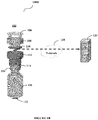
- Figure 1B depicts an exploded view of an item according to an exemplary embodiment of the invention.
- the item 102 may further comprise, but is not limited to, an electrochromic strip 108, a cap 104, a processor 110, a sensor 114, a metal crimp 116, and/or a thermochromics paper strip 122.
- the housing 112 may provide an enclosure to the sensor 114 and/or the processor 110.
- the metal crimp 116 may be wrapped around neck of the body 106 or may be wrapped inside the neck of the body 106 of the item 102. Wrapping the metal crimp 116 around neck of the body 106 may position the metal crimp 116 in such a way that the metal crimp 116 stays near to the content present inside the body 106 of the item 102. Also can be seen in Figure 1B , the metal crimp 116 may be coupled with the sensor 114 of the item 102. In this way, the metal crimp 116 coupled with the sensor 114 may be adapted to sense temperature of the content present inside the item 102 as the temperature or energy of the content will also get transferred to the metal crimp 116.
- the temperature of the content inside the item 102 may be nearly similar to the temperature of the metal crimp 116.
- the metal crimp 116 may be equally warm as the content will be inside the body 106 of the item 102.
- the metal crimp 116 may also be as cold as the content will be inside the body 106 of the item 102.
- This embodiment of the present invention provides a technical advantage of using effective and accurate temperature of content inside an item for taking appropriate measures.
- the sensor 114 may be coupled with the metal crimp 116. This would enable the sensor 114 to sense the temperature of content through the metal crimp 116. Based on the sensing of the temperature of content through the metal crimp 116, the sensor 114 may be adapted to determine a value of the temperature provided by the metal crimp 116. For an instance, the value of the temperature determined by the sensor 114 is 10° Celsius. The sensor 114 along with the processor 110 or the sensor 114 alone may determine if the value of the temperature falls within or outside a pre-defined temperature range. In an exemplary embodiment, the sensor 114 may correspond to a resistance temperature detector (RTD) or a platinum resistance thermometer (PRT) that is known in the art.
- RTD resistance temperature detector
- PRT platinum resistance thermometer
- the sensor 114 may also be communicably coupled with the electrochromic strip 108 of the item 102 so that the sensor 114 may communicate the temperature value to the electrochromic strip 108 to display a pre-defined color after administered or reaching the end user.
- a pre-defined color may be selected and enabled in the electrochromic strip 108.
- the value of the temperature falls within a pre-defined temperature range, then such an indication may be displayed on the electrochromic strip 108 using green color.
- the value of the temperature falls outside a pre-defined temperature range, then such an indication may be displayed on the electrochromic strip 108 using red color. This is explained in greater detailbelow with reference to Figure 1C .
- the electrochromic strip 108 may take power/charge from a battery of the item 102.
- the electrochromic strip 108 for displaying the indication may correspond to a reversible electrochromic strip.
- the electrochromic strip 108 may be reversible as the electrochromic strip 108 along with the tracking device assembly may be returned back to a manufacturer of the item 102 or a manufacturer of the content inside the item 102 after the item 102 is administered to the user of the item 102.
- the electrochromic strip 108 may be adapted to display an indication of the temperature value as communicated by the sensor 114.
- the indication of the temperature value may be displayed on the electrochromic strip 108 using different colors for a user of the item 102.
- the item 102 may further comprise the thermochromics paper strip 122 placed at bottom of the item 102 as shown in the Figure 1B .
- the thermochromics paper strip 122 is explained below in greater detail.
- FIG. 1C depicts an electrochromic strip of an exemplary item.
- the electrochromic strip 108 may have various indicators for the user. Various indicators have been explained with examples herein. If the temperature value is or above a first pre-defined temperature threshold (may be 25° Celsius), then the indication of the temperature value with red color may be displayed on the electrochromic strip 108. The red color may inform a user of the item 102 that content inside the item 102 is unfit for consumption. If the temperature value is below a second pre-defined temperature threshold (may be 8° Celsius), then, the indication of the temperature value with green color may be displayed on the electrochromic strip 108. The green color may inform the user of the item 102 that content inside the item 102 is fit for consumption.
- a first pre-defined temperature threshold may be 25° Celsius
- the indication of the temperature value with red color may be displayed on the electrochromic strip 108.
- the red color may inform a user of the item 102 that content inside the item 102 is unfit for consumption.
- Yellow color may also be displayed on the electrochromic strip 108 when the tracking device assembly is used and thereby detached from the item 102 after the content inside item 102 is administered to the user. Then, the tracking device assembly may be returned back to the manufacturer of the item 102 or the manufacturer of the content inside the item 102.
- the yellow color indication on the electrochromic strip 108 will give information to the manufacturer of the content/item 102 for separating out "used” vs "new" tracking devices assembly. Further, the electrochromic strip 108 may indicate yellow color once a switch in the tracking device assembly gets un-pressed. If the switch is pressed, then this means that the item 102 is still unused and still attached to tracking device assembly.
- the electrochromic strip 108 may comprise three different layers of electrochromic strips i.e. a red color electrochromic strip 108A, a yellow color electrochromic strip 108C and a green color electrochromic strip 108B for providing indication to the user.
- the power/charge from a battery 124 of the item 102 flows to a respective layer of the electrochromic strip.
- Such layers of the electrochromic strips are not more than 0.3 millimeter (mm) (may be of 0.1mm each and have protective coating).
- the sensor 114 provides the temperature value feedback to show green color when the temperature value is below the second pre-defined temperature threshold then 1-2 volts of power may be given to the green color layer of the electrochromic strip 108B.
- 1-2 volts of power may be given to the red color layer of the electrochromic strip 108A.
- the item 102 may further comprise an irreversible thermochromics paper strip 122.
- the thermochromics paper strip 122 may be placed at the bottom of the item 102. Placing the thermochromics paper strip 122 on the bottom of the item 102 would enable the thermochromics paper strip 122 to sense temperature of the item 102 through the body of the item 102 during the transit until the content inside the item 102 is administered/consumed by the user. Also, the thermochromics paper strip 122 is always placed at the bottom of the item 102 to restrict any kind of human touch interaction with the thermochromics paper strip 122.
- thermochromics paper strip 122 By not restricting the human touch interaction on the thermochromics paper strip 122, the body temperature of the human may be reflected on the thermochromics paper strip 122 through red color indication which would create adverse effects and thus, provide a wrong temperature indication.
- the thermochromics paper strip 122 may have such properties (or material) to sense the temperature of the body 106 of the item 102.
- the thermochromics paper strip 122 may be an irreversible thermo-chromic paper strip 122 as the thermo-chromic paper strip 122 would remain attached to the item 102 even after the item 102 is administered to the user.
- thermochromics paper strip 122 would not be returned back (unlike the electrochromic strip 108) to the manufacturer of the item or the manufacturer of the content inside the item 102. This would enable the thermochromics paper strip 122 to continue sensing and indicating the temperature of the item 102 to the user even after the electrochromic strip 108 is returned back to the manufacturer.
- the independent sensing and displaying temperature by the electrochromic strip 108 and the thermochromics paper strip 122 on the item 102 would provide a technical advantage of providing alternative mistake proofing and an immediate solution to inform the user about the health of content inside the item 102 even if one of these strips do not work or fails to indicate.
- the visual indication provides confidence to the end user for consumption of the content.
- thermochromics paper strip 122 may sense and indicate sensed temperature to the user in different colors like the electrochromic strip 108 does (as explained above). Specifically, the thermochromics paper strip 122 may change its color by sensing the temperature of the item 102. In an exemplary embodiment, the electrochromic strip 108 and the thermochromics paper strip 122 may show the same color at a time as both strips are sensing the temperature of the item 102. The property of sensing and indicating the temperature by the thermochromics paper strip is already known in the art. The thermochromics paper strip 122 may have another various indicator for the user of the item 102.
- thermochromics paper strip 122 If temperature sensed by the thermochromics paper strip 122 is at or above a first pre-defined temperature threshold (may be 25° Celsius), then the indication of the temperature with red color may be displayed on the thermochromics paper strip 122. The red color may inform a user of the item 102 that content inside the item 102 is unfit for consumption. If the temperature sensed by the thermochromics paper strip 122 is below a second pre-defined temperature threshold (may be 8° Celsius), then the indication of the temperature with green color may be displayed on the thermochromics paper strip 122. The green color may inform the user of the item 102 that content inside the item 102 is fit for consumption.
- a first pre-defined temperature threshold may be 25° Celsius
- thermochromics paper strip 122 If anytime during transit or at any location, the temperature measured by the thermochromics paper strip 122 reaches above the first pre-defined temperature threshold (i.e. 25° Celsius), then the red color indication will remain on the thermochromics paper strip 122 even if the item 102 is maintained at a desired temperature later on. In other words, once the item 102 is kept in an unsuitable environment (i.e. above the first pre-defined temperature threshold), then the indication with the red color would not get changed.
- the first pre-defined temperature threshold i.e. 25° Celsius
- the first pre-defined temperature threshold and/or the second pre-defined temperature threshold may be defined by a manufacturer of the content inside the item 102.
- the above-mentioned embodiments of the present invention provide a technical advantage of informing a user of an item about content present inside the item before using/consuming the item.
- This above-mentioned embodiments of the present invention provides another technical advantage of enabling the user to decide for either accepting or rejecting the item 102.
- the embodiments describe the indication of the temperature value on the electrochromic strip 108 and the thermochromics paper using three colors (red, yellow and green), it is understood by the person skilled in the art that any other form of indication of the temperature value on the electrochromic strip 108 is within the scope of the present invention.
- the sensor 114 may also be communicably coupled with the processor 110 of the item 102 so that the sensor 114 may transmit the temperature value to the processor 110.
- the processor 110 may be adapted to receive the temperature value and may validate the temperature value by comparing the temperature value with a pre-defined temperature range (such as the first pre-defined temperature threshold and the second pre-defined temperature threshold as described above). Also, when the processor 110 determines that the temperature value does not fall within the pre-defined temperature range based on the validation, the processor 110 may generate and transmit an alert to a server 120 through a communication unit (may be a transceiver) of the item 102 using a network 118. The processor 110 may generate and transmit the alert when the temperature value is or above the first pre-defined temperature threshold as explained above.
- the server 120 may be adapted to transmit such an alert to a user of the item 102 and/or a manufacturer of the item that the content inside the item 102 has become unfit for consumption.
- the sensor 114 may be communicably coupled with the server 120 so that the sensor 114 may directly transmit the temperature value to the server 120. Then, the server 120 may be adapted to receive the temperature value and may validate the temperature value as explained above.
- the sensor 114 may communicate with a thermostat (not shown) for controlling the temperature inside a container or a room where the item 102 is placed inside the container or the room.
- the thermostat may be responsible to maintain a particular temperature inside the container/room so that the content inside the item does not get stale/unfit.
- the thermostat may accordingly control the temperature inside the container/room.
- Figure IE depicts a cross-sectional view of an exemplary item 102. As can be seen in the cross-sectional view 100E of the item 102, the cap 104 is there and then the processor 110 is also present. Also shown are the sensor 114 of the item 102 and the body 106 of the item.
- Figure IF depicts a top view of an exemplary item 102 and
- Figure 1G depicts a bottom view of an exemplary item 102.
- Figure 2 depicts a flowchart outlining the features of an exemplary embodiment.
- the method flowchart 200 describes a method for sensing temperature inside an item and displaying an indication of the temperature thereof.
- the method flowchart 200 starts at step 202.
- a metal crimp 116 coupled with a sensor 114 may sense the temperature of content inside an item 102 and may also determine a value of the temperature through the metal crimp 116. This has been discussed above in greater detail.
- an electrochromic strip 108 coupled with the sensor 114 may display an indication of the temperature value. This has been discussed above in greater detail. Then, the method flowchart 200 may end at 208.
- the present invention is applicable in various fields such as, but not limited to, pharmaceutical industry, cosmetics industry, food industry and any such industry producing environmentally sensitive content and is well known in the art.
- Embodiments of the invention may use one or more computer readable devices.
- the one or more computer readable devices can be associated with an item 102.
- a computer readable medium comprises one or more processors and a memory coupled to the one or more processors, the memory stores instructions executed by the one or more processors.
- the one or more processors configured to sense, by a metal crimp 116 coupled with a sensor 114, a temperature of content inside an item 102 and determine a value of the temperature.
- the one or more processors are configured to display an indication of the temperature value on an electrochromic strip 108 coupled with the sensor 114.
- Exemplary computer readable media includes flash memory drives, digital versatile discs (DVDs), compact discs (CDs), floppy disks, and tape cassettes.
- Computer readable media comprise computer storage media and communication media.
- Computer storage media include volatile and non-volatile, removable and non-removable media implemented in any method or technology for storage of information such as computer readable instructions, data structures, program modules or other data.
- Computer storage media are tangible and mutually exclusive to communication media. Computer storage media are implemented in hardware and exclude carrier waves and propagated signals. Computer storage media as referenced herein are not signals per se.
- Exemplary computer storage media include hard disks, flash drives, and other solid-state memory.
- communication media typically embody computer readable instructions, data structures, program modules, or other data in a modulated data signal such as a carrier wave or other transport mechanism and include any information delivery media.
- processor can refer to substantially any computing processing unit or device comprising, but not limited to comprising, single-core processors; single-processors with software multithread execution capability; multi-core processors; multi-core processors with software multithread execution capability; multi-core processors with hardware multithread technology; parallel platforms; and parallel platforms with distributed shared memory.
- a processor can refer to an integrated circuit, an application specific integrated circuit (ASIC), a digital signal processor (DSP), a field programmable gate array (FPGA), a programmable logic controller (PLC), a complex programmable logic device (CPLD), a discrete gate or transistor logic, discrete hardware components, or any combination thereof designed to perform the functions described herein.
- ASIC application specific integrated circuit
- DSP digital signal processor
- FPGA field programmable gate array
- PLC programmable logic controller
- CPLD complex programmable logic device
- Nano-scale architectures such as, but not limited to, molecular and quantum-dot based transistors, switches and gates, in order to optimize space usage or enhance performance of user equipment.
- a processor may also be implemented as a combination of computing processing units.
- non-volatile memory can include read only memory (ROM), programmable ROM (PROM), electrically programmable ROM (EPROM), electrically erasable ROM (EEPROM), or flash memory.
- Volatile memory can include random access memory (RAM), which acts as external cache memory.
- RAM is available in many forms such as synchronous RAM (SRAM), dynamic RAM (DRAM), synchronous DRAM (SDRAM), double data rate SDRAM (DDR SDRAM), enhanced SDRAM (ESDRAM), Synch link DRAM (SLDRAM), and direct Rambus RAM (DRRAM).
- SRAM synchronous RAM
- DRAM dynamic RAM
- SDRAM synchronous DRAM
- DDR SDRAM double data rate SDRAM
- ESDRAM enhanced SDRAM
- SLDRAM Synch link DRAM
- DRRAM direct Rambus RAM
- the disclosed memory components of systems or methods herein are intended to comprise, without being limited to comprising, these and any other suitable types of memory.
Landscapes
- Physics & Mathematics (AREA)
- General Physics & Mathematics (AREA)
- Measuring Temperature Or Quantity Of Heat (AREA)
Abstract
Description
- The present invention generally relates to items. More particularly, the invention relates to sensing temperature inside an item.
- A variety of goods are packaged and transported from one place to another, both over short and long distances. The goods may be in the form of one or more items having contents therein. Some contents may be sensitive to environmental factors such as temperature, humidity, pressure etc. Manufacturers of items with sensitive content may define a specific threshold or a limit for maintaining a particular range of temperature in order to keep the contents of the items fresh or prevent them from becoming stale/unusable. A variation in temperature beyond the stipulated limit may cause adverse effects on the contents of the items during transportation or even if they are kept in a storage. Such effects could be a change in the chemical composition, or discoloration or a general degradation of the content which may render them non-consumable/unusable for end consumers. However, when the item reaches the end consumers, the consumers will be oblivious to such changes as there is no way to communicate changes to them.
- Existing solutions in the market monitor only environmental/outside temperature of these items i.e. the temperature at which these items are kept and do not monitor the temperature inside the items where the content resides. In absence of knowledge about the actual temperature inside the item, the end consumer as well as the manufacturers of items would not be able to take any necessary measure to protect the contents inside the item.
- In view of the aforementioned problems in the existing solutions, there is a need for an effective solution for sensing temperature inside an item. There is also a requirement of an effective solution for informing an end consumer regarding the temperature inside the item. In order to solve the problems in the existing solutions, an item and a method are disclosed.
- According to a first aspect of the invention an item for sensing temperature inside an item and displaying an indication of the temperature thereof is provided. The item comprises a metal crimp coupled with a sensor adapted to sense a temperature of content inside the item and determine a value of the temperature. The item comprises an electrochromic strip coupled with the sensor and adapted to display an indication of the temperature value.
- The item may further comprise a processor communicably coupled with the sensor. Also, the sensor may be adapted to transmit the temperature value to the processor.
- The processor may further validate the temperature value by comparing the temperature value with a pre-defined temperature range.
- The processor may transmit the validation to a server for generating an alert for a manufacturer and/or a user when the temperature value does not fall within the pre-defined temperature range.
- The sensor may communicate with a thermostat for controlling the temperature.
- The electrochromic strip for displaying the indication may correspond to a reversible electrochromic strip
- The indication of the temperature value may be displayed on the electrochromic strip using different colors for a user of the item. Also, the indication of the temperature value with a red color displayed on the electrochromic strip may inform the user that content inside the item is unfit for consumption.
- The metal crimp coupled with the item may be an aluminum crimp.
- The sensor communicably coupled with the metal crimp may correspond to a resistance temperature detector (RTD) or a platinum resistance thermometer (PRT).
- The item may be coupled with an irreversible thermochromic paper to sense and indicate a temperature of the item. Also, the irreversible thermo-chromic paper may be placed at bottom of the item.
- According to a second aspect of the invention, a method for sensing temperature inside an item and displaying an indication of the temperature thereof is provided. The method comprises step of sensing, by a metal crimp coupled with a sensor, a temperature of content inside an item and determining a value of the temperature. The method further comprises step of displaying an indication of the temperature value on an electrochromic strip coupled with the sensor.
- The item may further comprise a processor communicably coupled with the sensor. Also, the sensor may transmit the temperature value to the processor.
- The processor may further validate the temperature value by comparing the temperature value with a pre-defined temperature range.
- The processor may transmit the validation to a server for generating an alert for a manufacturer and/or a user when the temperature value does not fall within the pre-defined temperature range.
- The electrochromic strip for displaying the indication may correspond to a reversible electrochromic strip.
- The indication of the temperature value may be displayed on the electrochromic strip using different colors for a user of the item. Also, the indication of the temperature value with a red color displayed on the electrochromic strip may inform the user that content inside the item is unfit for consumption.
- The metal crimp coupled with the item may be an aluminum crimp.
- According to another aspect of the invention, a computer readable medium is provided, which may be for configuring a system for sensing temperature inside an item and displaying an indication of the temperature thereof. The computer readable medium comprises instructions executable by a computer processor in order to configure the processor to carry out the method of the second aspect as well as optionally any optional feature thereof. The computer readable medium may comprise one or more processors and a memory coupled to the one or more processors, where the memory stores the instructions that, in use, are executed by the one or more processors. The one or more processors are configured by the instructions to sense, by a metal crimp coupled with a sensor, a temperature of content inside an item and determine a value of the temperature. The one or more processors are further configured to display an indication of the temperature value on an electrochromic strip coupled with the sensor.
- Other advantages, and salient features of the invention will become apparent to those skilled in the art from the following detailed description, which taken in conjunction with the annexed drawings, discloses exemplary embodiments of the invention.
- Certain exemplary embodiments will now be described in greater detail by way of example only and with reference to the accompanying drawings in which:
-
Figure 1A depicts an assembled view of an exemplary item andFigure 1B depicts an exploded view of an exemplary item; -
Figure 1C depicts an electrochromic strip of an exemplary item, Figure ID depicts various colors of electrochromic strips of an exemplary item, Figure IE depicts a cross-sectional view of an exemplary item, Figure IF depicts a top view of an exemplary item, andFigure 1G depicts a bottom view of an exemplary item; and -
Figure 2 depicts an exemplary flowchart illustrating a method relating to the system. - Corresponding reference numerals indicate corresponding parts throughout the drawings.
- Described herein is the technology with an item and a method for sensing temperature inside an item and displaying an indication of the temperature thereof. A metal strip may be coupled with a sensor to sense temperature of content present inside an item. Also, the metal strip and the sensor may be associated with the item. In an exemplary embodiment, the metal strip may be an aluminum strip.
- Based on sensing of the temperature of content present inside the item, the sensor may determine a value of the temperature. Further, the sensor may also be coupled with an electrochromic strip that may display an indication of the temperature value determined by the sensor. Such an indication would inform a user of the item if the content present inside the item is fit for consumption or not.
- As used herein, the item may comprise various components which have been described below in greater detail. Also, the item may be placed in a container or in a room and may also communicate with a server through a network. The item may include content for consumption or usage by a user. Such an item may be a bottle or a box having liquid content, solid content or semi solid content or any such item known in the art. The content in the item may be for any kind of consumption/usage and may be a pharmaceutical content, a liquid content, an eatable content, a lotion, a cream, tablets or any such content known in the art.
- As used herein, the sensor may be coupled with the metal crimp. Also, the sensor may correspond to a resistance temperature detector (RTD) or a platinum resistance thermometer (PRT). The sensor may also have capability to communicate with a thermostat that may control the temperature based on the temperature value determined by the sensor.
- As used herein, the server has processing capabilities as disclosed further in the specification. The server may be a cloud storage, a remote database, or any such storage known in the art.
- As used herein, the network may refer to a wired network, a mesh network, a cellular network (such as Global System for Mobile (GSM) network, a Long-Term Evolution (LTE) network, a code-division multiple access (CDMA) network, a narrow-band internet of thing (NB-IoT) technique or category M1 technique)), a short-range network (a Wi-Fi network, a ZigBee network, a Bluetooth network, or a Near-Field Communication technique) or any such network/technique that is known in the art.
-
Figure 1A depicts an assembled view of an item according to an exemplary embodiment of the invention. As can be seen in the assembledview 100A, anitem 102 may comprise acap 104 and abody 106. Thecap 104 may be positioned on an upper or top portion of theitem 102. Thecap 104 andhousing 112 may be used to lock theitem 102 by rotating thecap 104 andhousing 112 on thebody 106 in a clockwise direction and may be unlocked when thecap 104 andhousing 112 is rotated in an anti-clockwise direction. Also, thecap 104 and thehousing 112 may comprise a snap fit to lock theitem 102 and may be unlocked when thecap 104 as well as thehousing 112 are pulled out in opposite direction. In an exemplary embodiment, thecap 104 and thehousing 112 may be considered as a single component and as part of a tracking device assembly. The tracking device assembly (not shown) of theitem 102 may be used to track the location of theitem 102 during transit and may also monitor the external temperature of theitem 102. The tracking device assembly may be detached from theitem 102 once theitem 102 is administered to a user. Further, thebody 106 may have content that may be consumed/used by any user of theitem 102. -
Figure 1B depicts an exploded view of an item according to an exemplary embodiment of the invention. As depicted in the explodedview 100B, theitem 102 may further comprise, but is not limited to, anelectrochromic strip 108, acap 104, aprocessor 110, asensor 114, ametal crimp 116, and/or athermochromics paper strip 122. Thehousing 112 may provide an enclosure to thesensor 114 and/or theprocessor 110. - As can be seen, the
metal crimp 116 may be wrapped around neck of thebody 106 or may be wrapped inside the neck of thebody 106 of theitem 102. Wrapping themetal crimp 116 around neck of thebody 106 may position themetal crimp 116 in such a way that themetal crimp 116 stays near to the content present inside thebody 106 of theitem 102. Also can be seen inFigure 1B , themetal crimp 116 may be coupled with thesensor 114 of theitem 102. In this way, themetal crimp 116 coupled with thesensor 114 may be adapted to sense temperature of the content present inside theitem 102 as the temperature or energy of the content will also get transferred to themetal crimp 116. Since both themetal crimp 116 and the content are in very close proximity, the temperature of the content inside theitem 102 may be nearly similar to the temperature of themetal crimp 116. In other words, themetal crimp 116 may be equally warm as the content will be inside thebody 106 of theitem 102. Alternatively, themetal crimp 116 may also be as cold as the content will be inside thebody 106 of theitem 102. This embodiment of the present invention provides a technical advantage of using effective and accurate temperature of content inside an item for taking appropriate measures. - Further, as can be seen in
Figure 1B , thesensor 114 may be coupled with themetal crimp 116. This would enable thesensor 114 to sense the temperature of content through themetal crimp 116. Based on the sensing of the temperature of content through themetal crimp 116, thesensor 114 may be adapted to determine a value of the temperature provided by themetal crimp 116. For an instance, the value of the temperature determined by thesensor 114 is 10° Celsius. Thesensor 114 along with theprocessor 110 or thesensor 114 alone may determine if the value of the temperature falls within or outside a pre-defined temperature range. In an exemplary embodiment, thesensor 114 may correspond to a resistance temperature detector (RTD) or a platinum resistance thermometer (PRT) that is known in the art. - Furthermore, the
sensor 114 may also be communicably coupled with theelectrochromic strip 108 of theitem 102 so that thesensor 114 may communicate the temperature value to theelectrochromic strip 108 to display a pre-defined color after administered or reaching the end user. For a range of temperatures, a pre-defined color may be selected and enabled in theelectrochromic strip 108. For an instance, if the value of the temperature falls within a pre-defined temperature range, then such an indication may be displayed on theelectrochromic strip 108 using green color. And, if the value of the temperature falls outside a pre-defined temperature range, then such an indication may be displayed on theelectrochromic strip 108 using red color. This is explained in greater detailbelow with reference toFigure 1C . In order to display indication, theelectrochromic strip 108 may take power/charge from a battery of theitem 102. In an exemplary embodiment, theelectrochromic strip 108 for displaying the indication may correspond to a reversible electrochromic strip. Theelectrochromic strip 108 may be reversible as theelectrochromic strip 108 along with the tracking device assembly may be returned back to a manufacturer of theitem 102 or a manufacturer of the content inside theitem 102 after theitem 102 is administered to the user of theitem 102. Accordingly, theelectrochromic strip 108 may be adapted to display an indication of the temperature value as communicated by thesensor 114. Moreover, the indication of the temperature value may be displayed on theelectrochromic strip 108 using different colors for a user of theitem 102. Along with theelectrochromic strip 108, theitem 102 may further comprise thethermochromics paper strip 122 placed at bottom of theitem 102 as shown in theFigure 1B . Thethermochromics paper strip 122 is explained below in greater detail. -
Figure 1C depicts an electrochromic strip of an exemplary item. As can be seen inFigure 1C , theelectrochromic strip 108 may have various indicators for the user. Various indicators have been explained with examples herein. If the temperature value is or above a first pre-defined temperature threshold (may be 25° Celsius), then the indication of the temperature value with red color may be displayed on theelectrochromic strip 108. The red color may inform a user of theitem 102 that content inside theitem 102 is unfit for consumption. If the temperature value is below a second pre-defined temperature threshold (may be 8° Celsius), then, the indication of the temperature value with green color may be displayed on theelectrochromic strip 108. The green color may inform the user of theitem 102 that content inside theitem 102 is fit for consumption. Yellow color may also be displayed on theelectrochromic strip 108 when the tracking device assembly is used and thereby detached from theitem 102 after the content insideitem 102 is administered to the user. Then, the tracking device assembly may be returned back to the manufacturer of theitem 102 or the manufacturer of the content inside theitem 102. The yellow color indication on theelectrochromic strip 108 will give information to the manufacturer of the content/item 102 for separating out "used" vs "new" tracking devices assembly. Further, theelectrochromic strip 108 may indicate yellow color once a switch in the tracking device assembly gets un-pressed. If the switch is pressed, then this means that theitem 102 is still unused and still attached to tracking device assembly. - Figure ID depicts various colors of electrochromic strips of an exemplary item. As can be seen, the
electrochromic strip 108 may comprise three different layers of electrochromic strips i.e. a red colorelectrochromic strip 108A, a yellowcolor electrochromic strip 108C and a green color electrochromic strip 108B for providing indication to the user. Based on the temperature value provided by thesensor 114, the power/charge from abattery 124 of theitem 102 flows to a respective layer of the electrochromic strip. Such layers of the electrochromic strips are not more than 0.3 millimeter (mm) (may be of 0.1mm each and have protective coating). For an instance, if thesensor 114 provides the temperature value feedback to show green color when the temperature value is below the second pre-defined temperature threshold then 1-2 volts of power may be given to the green color layer of the electrochromic strip 108B. Similarly, if thesensor 114 provides the temperature value feedback to show red color when the temperature value is above or equal to the first pre-defined temperature threshold then 1-2 volts of power may be given to the red color layer of theelectrochromic strip 108A. And, after, if theitem 102 is unplugged from the tracking device assembly, then data from the switch is sent as a feedback to the yellow color layer of theelectrochromic strip 108C, where the charge or power supplied to green or red color layers ofelectrochromic strips 108A-108B is discharged and supplied to theyellow color layer 108C. - The
item 102 may further comprise an irreversiblethermochromics paper strip 122. Thethermochromics paper strip 122 may be placed at the bottom of theitem 102. Placing thethermochromics paper strip 122 on the bottom of theitem 102 would enable thethermochromics paper strip 122 to sense temperature of theitem 102 through the body of theitem 102 during the transit until the content inside theitem 102 is administered/consumed by the user. Also, thethermochromics paper strip 122 is always placed at the bottom of theitem 102 to restrict any kind of human touch interaction with thethermochromics paper strip 122. By not restricting the human touch interaction on thethermochromics paper strip 122, the body temperature of the human may be reflected on thethermochromics paper strip 122 through red color indication which would create adverse effects and thus, provide a wrong temperature indication. Specifically, thethermochromics paper strip 122 may have such properties (or material) to sense the temperature of thebody 106 of theitem 102. Further, thethermochromics paper strip 122 may be an irreversible thermo-chromic paper strip 122 as the thermo-chromic paper strip 122 would remain attached to theitem 102 even after theitem 102 is administered to the user. And thus, thethermochromics paper strip 122 would not be returned back (unlike the electrochromic strip 108) to the manufacturer of the item or the manufacturer of the content inside theitem 102. This would enable thethermochromics paper strip 122 to continue sensing and indicating the temperature of theitem 102 to the user even after theelectrochromic strip 108 is returned back to the manufacturer. The independent sensing and displaying temperature by theelectrochromic strip 108 and thethermochromics paper strip 122 on theitem 102 would provide a technical advantage of providing alternative mistake proofing and an immediate solution to inform the user about the health of content inside theitem 102 even if one of these strips do not work or fails to indicate. The visual indication provides confidence to the end user for consumption of the content. - Moreover, the
thermochromics paper strip 122 may sense and indicate sensed temperature to the user in different colors like theelectrochromic strip 108 does (as explained above). Specifically, thethermochromics paper strip 122 may change its color by sensing the temperature of theitem 102. In an exemplary embodiment, theelectrochromic strip 108 and thethermochromics paper strip 122 may show the same color at a time as both strips are sensing the temperature of theitem 102. The property of sensing and indicating the temperature by the thermochromics paper strip is already known in the art. Thethermochromics paper strip 122 may have another various indicator for the user of theitem 102. If temperature sensed by thethermochromics paper strip 122 is at or above a first pre-defined temperature threshold (may be 25° Celsius), then the indication of the temperature with red color may be displayed on thethermochromics paper strip 122. The red color may inform a user of theitem 102 that content inside theitem 102 is unfit for consumption. If the temperature sensed by thethermochromics paper strip 122 is below a second pre-defined temperature threshold (may be 8° Celsius), then the indication of the temperature with green color may be displayed on thethermochromics paper strip 122. The green color may inform the user of theitem 102 that content inside theitem 102 is fit for consumption. If anytime during transit or at any location, the temperature measured by thethermochromics paper strip 122 reaches above the first pre-defined temperature threshold (i.e. 25° Celsius), then the red color indication will remain on thethermochromics paper strip 122 even if theitem 102 is maintained at a desired temperature later on. In other words, once theitem 102 is kept in an unsuitable environment (i.e. above the first pre-defined temperature threshold), then the indication with the red color would not get changed. - As used herein, the first pre-defined temperature threshold and/or the second pre-defined temperature threshold may be defined by a manufacturer of the content inside the
item 102. The above-mentioned embodiments of the present invention provide a technical advantage of informing a user of an item about content present inside the item before using/consuming the item. This above-mentioned embodiments of the present invention provides another technical advantage of enabling the user to decide for either accepting or rejecting theitem 102. Although the embodiments describe the indication of the temperature value on theelectrochromic strip 108 and the thermochromics paper using three colors (red, yellow and green), it is understood by the person skilled in the art that any other form of indication of the temperature value on theelectrochromic strip 108 is within the scope of the present invention. - Moreover, the
sensor 114 may also be communicably coupled with theprocessor 110 of theitem 102 so that thesensor 114 may transmit the temperature value to theprocessor 110. Theprocessor 110 may be adapted to receive the temperature value and may validate the temperature value by comparing the temperature value with a pre-defined temperature range (such as the first pre-defined temperature threshold and the second pre-defined temperature threshold as described above). Also, when theprocessor 110 determines that the temperature value does not fall within the pre-defined temperature range based on the validation, theprocessor 110 may generate and transmit an alert to aserver 120 through a communication unit (may be a transceiver) of theitem 102 using anetwork 118. Theprocessor 110 may generate and transmit the alert when the temperature value is or above the first pre-defined temperature threshold as explained above. - When the
server 120 receives the alert, theserver 120 may be adapted to transmit such an alert to a user of theitem 102 and/or a manufacturer of the item that the content inside theitem 102 has become unfit for consumption. Alternatively, thesensor 114 may be communicably coupled with theserver 120 so that thesensor 114 may directly transmit the temperature value to theserver 120. Then, theserver 120 may be adapted to receive the temperature value and may validate the temperature value as explained above. - The
sensor 114 may communicate with a thermostat (not shown) for controlling the temperature inside a container or a room where theitem 102 is placed inside the container or the room. The thermostat may be responsible to maintain a particular temperature inside the container/room so that the content inside the item does not get stale/unfit. When the thermostat receives the temperature value from thesensor 114, the thermostat may accordingly control the temperature inside the container/room. - Figure IE depicts a cross-sectional view of an
exemplary item 102. As can be seen in thecross-sectional view 100E of theitem 102, thecap 104 is there and then theprocessor 110 is also present. Also shown are thesensor 114 of theitem 102 and thebody 106 of the item. Figure IF depicts a top view of anexemplary item 102 andFigure 1G depicts a bottom view of anexemplary item 102. -
Figure 2 depicts a flowchart outlining the features of an exemplary embodiment. Themethod flowchart 200 describes a method for sensing temperature inside an item and displaying an indication of the temperature thereof. Themethod flowchart 200 starts atstep 202. - At
step 204, ametal crimp 116 coupled with asensor 114 may sense the temperature of content inside anitem 102 and may also determine a value of the temperature through themetal crimp 116. This has been discussed above in greater detail. - At
step 206, anelectrochromic strip 108 coupled with thesensor 114 may display an indication of the temperature value. This has been discussed above in greater detail. Then, themethod flowchart 200 may end at 208. - The present invention is applicable in various fields such as, but not limited to, pharmaceutical industry, cosmetics industry, food industry and any such industry producing environmentally sensitive content and is well known in the art.
- Embodiments of the invention may use one or more computer readable devices. The one or more computer readable devices can be associated with an
item 102. A computer readable medium comprises one or more processors and a memory coupled to the one or more processors, the memory stores instructions executed by the one or more processors. The one or more processors configured to sense, by ametal crimp 116 coupled with asensor 114, a temperature of content inside anitem 102 and determine a value of the temperature. The one or more processors are configured to display an indication of the temperature value on anelectrochromic strip 108 coupled with thesensor 114. - Exemplary computer readable media includes flash memory drives, digital versatile discs (DVDs), compact discs (CDs), floppy disks, and tape cassettes. By way of example and not limitation, computer readable media comprise computer storage media and communication media. Computer storage media include volatile and non-volatile, removable and non-removable media implemented in any method or technology for storage of information such as computer readable instructions, data structures, program modules or other data. Computer storage media are tangible and mutually exclusive to communication media. Computer storage media are implemented in hardware and exclude carrier waves and propagated signals. Computer storage media as referenced herein are not signals per se. Exemplary computer storage media include hard disks, flash drives, and other solid-state memory. In contrast, communication media typically embody computer readable instructions, data structures, program modules, or other data in a modulated data signal such as a carrier wave or other transport mechanism and include any information delivery media.
- Although described in connection with an exemplary computing system environment, the examples herein are capable of implementation with numerous other general purpose or special purpose computing system environments, configurations, or devices. Implementations of the embodiments herein may be described in the general context of computer-executable instructions, such as program modules, executed by one or more computers or other devices in software, firmware, hardware, or a combination thereof. The computer-executable instructions may be organized into one or more computer-executable components or modules. Generally, program modules include, but are not limited to, routines, programs, objects, components, and data structures that perform particular tasks or implement particular abstract data types. There may be any number and organization of such components or modules. There is no limitation to the specific computer-executable instructions or the specific components or modules illustrated in the Figures/Tables and described herein. Other examples may include different computer-executable instructions or components having more or less functionality than illustrated and described herein. A general-purpose computer may transform into a special-purpose computing device when configured to execute the instructions described herein.
- The order of execution or performance of the operations in the examples illustrated and described herein is not essential, unless otherwise specified. That is, the operations may be performed in any order, unless otherwise specified, and the embodiments may include additional or fewer operations than those disclosed herein. For example, executing or performing a particular operation before, contemporaneously with, or after another operation is contemplated.
- As it employed in the subject specification, the term "processor" can refer to substantially any computing processing unit or device comprising, but not limited to comprising, single-core processors; single-processors with software multithread execution capability; multi-core processors; multi-core processors with software multithread execution capability; multi-core processors with hardware multithread technology; parallel platforms; and parallel platforms with distributed shared memory. Additionally, a processor can refer to an integrated circuit, an application specific integrated circuit (ASIC), a digital signal processor (DSP), a field programmable gate array (FPGA), a programmable logic controller (PLC), a complex programmable logic device (CPLD), a discrete gate or transistor logic, discrete hardware components, or any combination thereof designed to perform the functions described herein. Processors can exploit Nano-scale architectures such as, but not limited to, molecular and quantum-dot based transistors, switches and gates, in order to optimize space usage or enhance performance of user equipment. A processor may also be implemented as a combination of computing processing units.
- In the subject specification, terms such as "data store," "data storage," "database," "cache," and substantially any other information storage component relevant to operation and functionality of a component, refer to "memory components," or entities embodied in a "memory" or components comprising the memory. It will be appreciated that the memory components, or computer-readable storage media, described herein can be either volatile memory or non-volatile memory, or can include both volatile and non-volatile memory. By way of illustration, and not limitation, non-volatile memory can include read only memory (ROM), programmable ROM (PROM), electrically programmable ROM (EPROM), electrically erasable ROM (EEPROM), or flash memory. Volatile memory can include random access memory (RAM), which acts as external cache memory. By way of illustration and not limitation, RAM is available in many forms such as synchronous RAM (SRAM), dynamic RAM (DRAM), synchronous DRAM (SDRAM), double data rate SDRAM (DDR SDRAM), enhanced SDRAM (ESDRAM), Synch link DRAM (SLDRAM), and direct Rambus RAM (DRRAM). Additionally, the disclosed memory components of systems or methods herein are intended to comprise, without being limited to comprising, these and any other suitable types of memory.
- When introducing elements of aspects of the invention or the examples thereof, the articles "a," "an," "the," and "said" are intended to mean that there are one or more of the elements. The terms "comprising," "including," and "having" are intended to be inclusive and mean that there may be additional elements other than the listed elements. The term "exemplary" is intended to mean "an example of." The phrase "one or more of the following: A, B, and C" means "at least one of A and/or at least one of B and/or at least one of C".
- Having described embodiments of the invention in detail, it will be apparent that modifications and variations are possible without departing from the scope of the invention as defined in the appended claims. As various changes could be made in the above constructions, products, and methods, it is intended that all matter contained in the above description and shown in the accompanying drawings shall be interpreted as illustrative and not in a limiting sense.
- Although the subject matter has been described in language specific to structural features and/or acts, it is to be understood that the subject matter defined in the appended claims is not necessarily limited to the specific features or acts described above. Rather, the specific features and acts described above are disclosed as examples of implementing the claims and other equivalent features and acts are intended to be within the scope of the claims.
Claims (15)
- An item (102) comprising:a metal crimp (116) coupled with a sensor (114) adapted to sense temperature of content inside the item (102) and determine a value of the temperature; andan electrochromic strip (108) coupled with the sensor (114) and adapted to display an indication of the temperature value.
- The item (102) of claim 1, wherein the item further comprises a processor (110) communicably coupled with the sensor (114), wherein the sensor is adapted to transmit the temperature value to the processor.
- The item (102) of claim 2, wherein the processor (110) further validates the temperature value by comparing the temperature value with a pre-defined temperature range,
optionally wherein the processor (110) transmits the validation to a server (120) for generating an alert for a manufacturer and/or a user when the temperature value does not fall within the pre-defined temperature range. - The item (102) of claim 1, 2 or 3, wherein the sensor (114) communicates with a thermostat for controlling the temperature.
- The item (102) of any preceding claim, wherein the electrochromic strip (108) for displaying the indication corresponds to a reversible electrochromic strip.
- The item (102) of any preceding claim, wherein the indication of the temperature value is displayed on the electrochromic strip (108) using different colors for a user of the item,
optionally wherein the indication of the temperature value with a red color displayed on the electrochromic strip (108) informs the user that content inside the item (102) is unfit for consumption. - The item (102) of any preceding claim, wherein the metal crimp (116) coupled with the item is an aluminum crimp,
and/or wherein the sensor (114) communicably coupled with the metal crimp (116) corresponds to a resistance temperature detector (RTD) or a platinum resistance thermometer (PRT). - The item (102) of any preceding claim, wherein the item is coupled with an irreversible thermochromics paper (122) to sense and indicate a temperature of the item (102), wherein the irreversible thermochromics paper is placed at the bottom of the item.
- A method comprising:sensing, by a metal crimp (116) coupled with a sensor (114), a temperature of content inside an item (102) and determining a value of the temperature; anddisplaying an indication of the temperature value on an electrochromic strip (108) coupled with the sensor (114).
- The method of claim 9, wherein the item (102) further comprises a processor (110) communicably coupled with the sensor (114), wherein the sensor transmits the temperature value to the processor.
- The method of claim 10, wherein the processor (110) further validates the temperature value by comparing the temperature value with a pre-defined temperature range,
optionally wherein the processor (110) transmits the validation to a server (120) for generating an alert for a manufacturer and/or a user when the temperature value does not fall within the pre-defined temperature range. - The method of claim 9, 10, or 11, wherein the electrochromic strip (108) for displaying the indication corresponds to a reversible electrochromic strip.
- The method of any of claims 9 to 12, wherein the indication of the temperature value is displayed on the electrochromic strip (108) using different colors for a user of the item,
optionally wherein the indication of the temperature value with a red color displayed on the electrochromic strip (108) informs the user that content inside the item is unfit for consumption. - The method of any of claims 9 to 13, wherein the metal crimp (112) coupled with the item is an aluminum crimp.
- A computer readable medium comprising instructions for execution by one or more processors, in order to configure the one or more processors to carry out the method of any of claims 9 to 14.
Applications Claiming Priority (1)
| Application Number | Priority Date | Filing Date | Title |
|---|---|---|---|
| IN202011005428 | 2020-02-07 |
Publications (2)
| Publication Number | Publication Date |
|---|---|
| EP3862734A1 true EP3862734A1 (en) | 2021-08-11 |
| EP3862734B1 EP3862734B1 (en) | 2025-04-16 |
Family
ID=73834395
Family Applications (1)
| Application Number | Title | Priority Date | Filing Date |
|---|---|---|---|
| EP20213598.4A Active EP3862734B1 (en) | 2020-02-07 | 2020-12-11 | An item and a method for sensing and displaying temperature thereof |
Country Status (2)
| Country | Link |
|---|---|
| US (1) | US11913841B2 (en) |
| EP (1) | EP3862734B1 (en) |
Families Citing this family (2)
| Publication number | Priority date | Publication date | Assignee | Title |
|---|---|---|---|---|
| JP6660972B2 (en) * | 2018-03-20 | 2020-03-11 | 株式会社メディパルホールディングス | Delivery unit and delivery system |
| CN114878017B (en) * | 2022-04-28 | 2026-03-17 | 深圳市摩范标签材料有限公司 | A method and equipment for detecting the color change temperature of thermochromic materials |
Citations (4)
| Publication number | Priority date | Publication date | Assignee | Title |
|---|---|---|---|---|
| US4257683A (en) * | 1978-01-24 | 1981-03-24 | Sharp Kabushiki Kaisha | Electrochromic display |
| US5749656A (en) * | 1995-08-11 | 1998-05-12 | General Motors Corporation | Thermal probe assembly with mold-over crimp sensor packaging |
| US20150187234A1 (en) * | 2010-12-30 | 2015-07-02 | Paul Atkinson | Intelligent label device and method |
| US20180144596A1 (en) * | 2016-11-23 | 2018-05-24 | Eric Squatrito | Clippable air condition monitor device |
Family Cites Families (12)
| Publication number | Priority date | Publication date | Assignee | Title |
|---|---|---|---|---|
| US6929136B2 (en) * | 2002-01-08 | 2005-08-16 | Fabricas Monterrey, S.A. De C.V. | Thermochromic cap |
| EP1921018A1 (en) * | 2006-11-07 | 2008-05-14 | Enotop S.L. | Temperature sensitive closure cap |
| US20080184927A1 (en) * | 2007-02-02 | 2008-08-07 | Paul Phong Anh Pham | Container cap for assuring quality |
| US8215835B2 (en) | 2007-12-11 | 2012-07-10 | Tokitae Llc | Temperature-stabilized medicinal storage systems |
| US20140136430A1 (en) | 2012-11-15 | 2014-05-15 | Gary Pope | Product integrity monitor |
| GB2516006B (en) * | 2013-06-06 | 2016-10-12 | Starspot Ltd | Wine thermometer |
| US9599028B2 (en) * | 2014-09-08 | 2017-03-21 | General Electric Company | Bulk flame temperature regulator for dry low emission engines |
| US20170352002A1 (en) | 2016-06-01 | 2017-12-07 | Mega Link Technology Limited | System and method for real time remote monitoring of atmospheric conditions of products |
| NO20170237A1 (en) * | 2017-02-16 | 2018-08-17 | Keep It Tech As | Screw cap system |
| DE102018109233B4 (en) | 2018-04-18 | 2025-01-23 | Hanon Systems | System for connecting housing elements of a heat transfer device |
| CN112136012A (en) | 2018-04-19 | 2020-12-25 | 恩伯技术公司 | Portable cooler with active temperature control |
| DE202021106105U1 (en) * | 2021-11-09 | 2021-12-14 | Feli-X GmbH Holding i.G. | bottle cap |
-
2020
- 2020-12-09 US US17/116,495 patent/US11913841B2/en active Active
- 2020-12-11 EP EP20213598.4A patent/EP3862734B1/en active Active
Patent Citations (4)
| Publication number | Priority date | Publication date | Assignee | Title |
|---|---|---|---|---|
| US4257683A (en) * | 1978-01-24 | 1981-03-24 | Sharp Kabushiki Kaisha | Electrochromic display |
| US5749656A (en) * | 1995-08-11 | 1998-05-12 | General Motors Corporation | Thermal probe assembly with mold-over crimp sensor packaging |
| US20150187234A1 (en) * | 2010-12-30 | 2015-07-02 | Paul Atkinson | Intelligent label device and method |
| US20180144596A1 (en) * | 2016-11-23 | 2018-05-24 | Eric Squatrito | Clippable air condition monitor device |
Also Published As
| Publication number | Publication date |
|---|---|
| EP3862734B1 (en) | 2025-04-16 |
| US20210247237A1 (en) | 2021-08-12 |
| US11913841B2 (en) | 2024-02-27 |
Similar Documents
| Publication | Publication Date | Title |
|---|---|---|
| US9846086B1 (en) | System and method for time-temperature monitoring of transportable goods | |
| US11913841B2 (en) | Item and a method for sensing and displaying temperature therof | |
| US20120174853A1 (en) | Temperature Sensing Food Stuff Label | |
| US20070258048A1 (en) | Monitoring Expiration Dates of Perishable Products | |
| US6425343B1 (en) | Shape memory alloy thermal exposure monitor | |
| US10817825B2 (en) | Remote integration of cloud services and transportable perishable products active monitor | |
| US10342737B1 (en) | Active monitoring system for thermally-managed transportation and storage of specific perishable products | |
| US11703394B2 (en) | Systems and methods for smart thermocouple temperature probe | |
| CN102132336A (en) | Labels used to show high temperature exposure | |
| CN112469979A (en) | Flexible sensor label system | |
| Wan et al. | A new type of TTI based on an electrochemical pseudo transistor | |
| EP2642436A1 (en) | A wireless device and a wireless platform for real-time monitoring of perishable products during transport | |
| US9410852B2 (en) | Freeze indicator | |
| AU2018371678A1 (en) | Thermal response probe and method | |
| US12025508B2 (en) | System and method for monitoring a container environment | |
| JP7508160B1 (en) | Transportation temperature monitoring device and transportation temperature monitoring system | |
| US7628117B2 (en) | Over temperature alarm indication apparatus | |
| Aung et al. | Cold chain monitoring tools | |
| US20080184927A1 (en) | Container cap for assuring quality | |
| US20220383252A1 (en) | A method and a system for tracking an item | |
| EP3997643A2 (en) | Remote integration of cloud services and transportable perishable products active monitor | |
| EP4049459B1 (en) | A method and an apparatus for providing smart suggestions | |
| US20230384281A1 (en) | Non-invasive method and system for detecting quality of packaged milk | |
| KR101813093B1 (en) | Measurement labels for product freshness | |
| US20210231326A1 (en) | A method and a system for monitoring items |
Legal Events
| Date | Code | Title | Description |
|---|---|---|---|
| PUAI | Public reference made under article 153(3) epc to a published international application that has entered the european phase |
Free format text: ORIGINAL CODE: 0009012 |
|
| STAA | Information on the status of an ep patent application or granted ep patent |
Free format text: STATUS: THE APPLICATION HAS BEEN PUBLISHED |
|
| AK | Designated contracting states |
Kind code of ref document: A1 Designated state(s): AL AT BE BG CH CY CZ DE DK EE ES FI FR GB GR HR HU IE IS IT LI LT LU LV MC MK MT NL NO PL PT RO RS SE SI SK SM TR |
|
| STAA | Information on the status of an ep patent application or granted ep patent |
Free format text: STATUS: REQUEST FOR EXAMINATION WAS MADE |
|
| 17P | Request for examination filed |
Effective date: 20220211 |
|
| RBV | Designated contracting states (corrected) |
Designated state(s): AL AT BE BG CH CY CZ DE DK EE ES FI FR GB GR HR HU IE IS IT LI LT LU LV MC MK MT NL NO PL PT RO RS SE SI SK SM TR |
|
| STAA | Information on the status of an ep patent application or granted ep patent |
Free format text: STATUS: EXAMINATION IS IN PROGRESS |
|
| 17Q | First examination report despatched |
Effective date: 20230711 |
|
| GRAP | Despatch of communication of intention to grant a patent |
Free format text: ORIGINAL CODE: EPIDOSNIGR1 |
|
| STAA | Information on the status of an ep patent application or granted ep patent |
Free format text: STATUS: GRANT OF PATENT IS INTENDED |
|
| INTG | Intention to grant announced |
Effective date: 20241121 |
|
| GRAS | Grant fee paid |
Free format text: ORIGINAL CODE: EPIDOSNIGR3 |
|
| GRAA | (expected) grant |
Free format text: ORIGINAL CODE: 0009210 |
|
| STAA | Information on the status of an ep patent application or granted ep patent |
Free format text: STATUS: THE PATENT HAS BEEN GRANTED |
|
| AK | Designated contracting states |
Kind code of ref document: B1 Designated state(s): AL AT BE BG CH CY CZ DE DK EE ES FI FR GB GR HR HU IE IS IT LI LT LU LV MC MK MT NL NO PL PT RO RS SE SI SK SM TR |
|
| REG | Reference to a national code |
Ref country code: GB Ref legal event code: FG4D |
|
| REG | Reference to a national code |
Ref country code: CH Ref legal event code: EP |
|
| REG | Reference to a national code |
Ref country code: IE Ref legal event code: FG4D |
|
| REG | Reference to a national code |
Ref country code: DE Ref legal event code: R096 Ref document number: 602020049483 Country of ref document: DE |
|
| REG | Reference to a national code |
Ref country code: NL Ref legal event code: FP |
|
| REG | Reference to a national code |
Ref country code: AT Ref legal event code: MK05 Ref document number: 1785980 Country of ref document: AT Kind code of ref document: T Effective date: 20250416 |
|
| PG25 | Lapsed in a contracting state [announced via postgrant information from national office to epo] |
Ref country code: PT Free format text: LAPSE BECAUSE OF FAILURE TO SUBMIT A TRANSLATION OF THE DESCRIPTION OR TO PAY THE FEE WITHIN THE PRESCRIBED TIME-LIMIT Effective date: 20250818 Ref country code: FI Free format text: LAPSE BECAUSE OF FAILURE TO SUBMIT A TRANSLATION OF THE DESCRIPTION OR TO PAY THE FEE WITHIN THE PRESCRIBED TIME-LIMIT Effective date: 20250416 Ref country code: ES Free format text: LAPSE BECAUSE OF FAILURE TO SUBMIT A TRANSLATION OF THE DESCRIPTION OR TO PAY THE FEE WITHIN THE PRESCRIBED TIME-LIMIT Effective date: 20250416 |
|
| REG | Reference to a national code |
Ref country code: LT Ref legal event code: MG9D |
|
| PG25 | Lapsed in a contracting state [announced via postgrant information from national office to epo] |
Ref country code: NO Free format text: LAPSE BECAUSE OF FAILURE TO SUBMIT A TRANSLATION OF THE DESCRIPTION OR TO PAY THE FEE WITHIN THE PRESCRIBED TIME-LIMIT Effective date: 20250716 Ref country code: GR Free format text: LAPSE BECAUSE OF FAILURE TO SUBMIT A TRANSLATION OF THE DESCRIPTION OR TO PAY THE FEE WITHIN THE PRESCRIBED TIME-LIMIT Effective date: 20250717 |
|
| PG25 | Lapsed in a contracting state [announced via postgrant information from national office to epo] |
Ref country code: PL Free format text: LAPSE BECAUSE OF FAILURE TO SUBMIT A TRANSLATION OF THE DESCRIPTION OR TO PAY THE FEE WITHIN THE PRESCRIBED TIME-LIMIT Effective date: 20250416 |
|
| PG25 | Lapsed in a contracting state [announced via postgrant information from national office to epo] |
Ref country code: BG Free format text: LAPSE BECAUSE OF FAILURE TO SUBMIT A TRANSLATION OF THE DESCRIPTION OR TO PAY THE FEE WITHIN THE PRESCRIBED TIME-LIMIT Effective date: 20250416 |
|
| PG25 | Lapsed in a contracting state [announced via postgrant information from national office to epo] |
Ref country code: HR Free format text: LAPSE BECAUSE OF FAILURE TO SUBMIT A TRANSLATION OF THE DESCRIPTION OR TO PAY THE FEE WITHIN THE PRESCRIBED TIME-LIMIT Effective date: 20250416 |
|
| PG25 | Lapsed in a contracting state [announced via postgrant information from national office to epo] |
Ref country code: AT Free format text: LAPSE BECAUSE OF FAILURE TO SUBMIT A TRANSLATION OF THE DESCRIPTION OR TO PAY THE FEE WITHIN THE PRESCRIBED TIME-LIMIT Effective date: 20250416 |
|
| PG25 | Lapsed in a contracting state [announced via postgrant information from national office to epo] |
Ref country code: RS Free format text: LAPSE BECAUSE OF FAILURE TO SUBMIT A TRANSLATION OF THE DESCRIPTION OR TO PAY THE FEE WITHIN THE PRESCRIBED TIME-LIMIT Effective date: 20250716 |
|
| PG25 | Lapsed in a contracting state [announced via postgrant information from national office to epo] |
Ref country code: IS Free format text: LAPSE BECAUSE OF FAILURE TO SUBMIT A TRANSLATION OF THE DESCRIPTION OR TO PAY THE FEE WITHIN THE PRESCRIBED TIME-LIMIT Effective date: 20250816 |
|
| PG25 | Lapsed in a contracting state [announced via postgrant information from national office to epo] |
Ref country code: LV Free format text: LAPSE BECAUSE OF FAILURE TO SUBMIT A TRANSLATION OF THE DESCRIPTION OR TO PAY THE FEE WITHIN THE PRESCRIBED TIME-LIMIT Effective date: 20250416 |
|
| PGFP | Annual fee paid to national office [announced via postgrant information from national office to epo] |
Ref country code: DE Payment date: 20251126 Year of fee payment: 6 |
|
| PG25 | Lapsed in a contracting state [announced via postgrant information from national office to epo] |
Ref country code: SM Free format text: LAPSE BECAUSE OF FAILURE TO SUBMIT A TRANSLATION OF THE DESCRIPTION OR TO PAY THE FEE WITHIN THE PRESCRIBED TIME-LIMIT Effective date: 20250416 Ref country code: DK Free format text: LAPSE BECAUSE OF FAILURE TO SUBMIT A TRANSLATION OF THE DESCRIPTION OR TO PAY THE FEE WITHIN THE PRESCRIBED TIME-LIMIT Effective date: 20250416 |
|
| REG | Reference to a national code |
Ref country code: DE Ref legal event code: R097 Ref document number: 602020049483 Country of ref document: DE |
|
| PG25 | Lapsed in a contracting state [announced via postgrant information from national office to epo] |
Ref country code: CZ Free format text: LAPSE BECAUSE OF FAILURE TO SUBMIT A TRANSLATION OF THE DESCRIPTION OR TO PAY THE FEE WITHIN THE PRESCRIBED TIME-LIMIT Effective date: 20250416 |
|
| PG25 | Lapsed in a contracting state [announced via postgrant information from national office to epo] |
Ref country code: EE Free format text: LAPSE BECAUSE OF FAILURE TO SUBMIT A TRANSLATION OF THE DESCRIPTION OR TO PAY THE FEE WITHIN THE PRESCRIBED TIME-LIMIT Effective date: 20250416 |
|
| PG25 | Lapsed in a contracting state [announced via postgrant information from national office to epo] |
Ref country code: RO Free format text: LAPSE BECAUSE OF FAILURE TO SUBMIT A TRANSLATION OF THE DESCRIPTION OR TO PAY THE FEE WITHIN THE PRESCRIBED TIME-LIMIT Effective date: 20250416 Ref country code: SK Free format text: LAPSE BECAUSE OF FAILURE TO SUBMIT A TRANSLATION OF THE DESCRIPTION OR TO PAY THE FEE WITHIN THE PRESCRIBED TIME-LIMIT Effective date: 20250416 |
|
| PG25 | Lapsed in a contracting state [announced via postgrant information from national office to epo] |
Ref country code: IT Free format text: LAPSE BECAUSE OF FAILURE TO SUBMIT A TRANSLATION OF THE DESCRIPTION OR TO PAY THE FEE WITHIN THE PRESCRIBED TIME-LIMIT Effective date: 20250416 |
|
| PLBE | No opposition filed within time limit |
Free format text: ORIGINAL CODE: 0009261 |
|
| STAA | Information on the status of an ep patent application or granted ep patent |
Free format text: STATUS: NO OPPOSITION FILED WITHIN TIME LIMIT |
|
| REG | Reference to a national code |
Ref country code: CH Ref legal event code: L10 Free format text: ST27 STATUS EVENT CODE: U-0-0-L10-L00 (AS PROVIDED BY THE NATIONAL OFFICE) Effective date: 20260225 |
|
| 26N | No opposition filed |
Effective date: 20260119 |