EP3862643A1 - Air conditioner, method for controlling air conditioner, and program - Google Patents
Air conditioner, method for controlling air conditioner, and program Download PDFInfo
- Publication number
- EP3862643A1 EP3862643A1 EP18903046.3A EP18903046A EP3862643A1 EP 3862643 A1 EP3862643 A1 EP 3862643A1 EP 18903046 A EP18903046 A EP 18903046A EP 3862643 A1 EP3862643 A1 EP 3862643A1
- Authority
- EP
- European Patent Office
- Prior art keywords
- air
- heat exchanger
- washing operation
- indoor fan
- indoor
- Prior art date
- Legal status (The legal status is an assumption and is not a legal conclusion. Google has not performed a legal analysis and makes no representation as to the accuracy of the status listed.)
- Withdrawn
Links
Images


Classifications
-
- F—MECHANICAL ENGINEERING; LIGHTING; HEATING; WEAPONS; BLASTING
- F24—HEATING; RANGES; VENTILATING
- F24F—AIR-CONDITIONING; AIR-HUMIDIFICATION; VENTILATION; USE OF AIR CURRENTS FOR SCREENING
- F24F11/00—Control or safety arrangements
- F24F11/30—Control or safety arrangements for purposes related to the operation of the system, e.g. for safety or monitoring
-
- F—MECHANICAL ENGINEERING; LIGHTING; HEATING; WEAPONS; BLASTING
- F24—HEATING; RANGES; VENTILATING
- F24F—AIR-CONDITIONING; AIR-HUMIDIFICATION; VENTILATION; USE OF AIR CURRENTS FOR SCREENING
- F24F11/00—Control or safety arrangements
- F24F11/30—Control or safety arrangements for purposes related to the operation of the system, e.g. for safety or monitoring
- F24F11/41—Defrosting; Preventing freezing
- F24F11/43—Defrosting; Preventing freezing of indoor units
-
- F—MECHANICAL ENGINEERING; LIGHTING; HEATING; WEAPONS; BLASTING
- F24—HEATING; RANGES; VENTILATING
- F24F—AIR-CONDITIONING; AIR-HUMIDIFICATION; VENTILATION; USE OF AIR CURRENTS FOR SCREENING
- F24F11/00—Control or safety arrangements
- F24F11/50—Control or safety arrangements characterised by user interfaces or communication
- F24F11/61—Control or safety arrangements characterised by user interfaces or communication using timers
-
- F—MECHANICAL ENGINEERING; LIGHTING; HEATING; WEAPONS; BLASTING
- F24—HEATING; RANGES; VENTILATING
- F24F—AIR-CONDITIONING; AIR-HUMIDIFICATION; VENTILATION; USE OF AIR CURRENTS FOR SCREENING
- F24F11/00—Control or safety arrangements
- F24F11/70—Control systems characterised by their outputs; Constructional details thereof
- F24F11/72—Control systems characterised by their outputs; Constructional details thereof for controlling the supply of treated air, e.g. its pressure
- F24F11/74—Control systems characterised by their outputs; Constructional details thereof for controlling the supply of treated air, e.g. its pressure for controlling air flow rate or air velocity
-
- F—MECHANICAL ENGINEERING; LIGHTING; HEATING; WEAPONS; BLASTING
- F24—HEATING; RANGES; VENTILATING
- F24F—AIR-CONDITIONING; AIR-HUMIDIFICATION; VENTILATION; USE OF AIR CURRENTS FOR SCREENING
- F24F2110/00—Control inputs relating to air properties
- F24F2110/10—Temperature
-
- F—MECHANICAL ENGINEERING; LIGHTING; HEATING; WEAPONS; BLASTING
- F24—HEATING; RANGES; VENTILATING
- F24F—AIR-CONDITIONING; AIR-HUMIDIFICATION; VENTILATION; USE OF AIR CURRENTS FOR SCREENING
- F24F2110/00—Control inputs relating to air properties
- F24F2110/20—Humidity
-
- F—MECHANICAL ENGINEERING; LIGHTING; HEATING; WEAPONS; BLASTING
- F24—HEATING; RANGES; VENTILATING
- F24F—AIR-CONDITIONING; AIR-HUMIDIFICATION; VENTILATION; USE OF AIR CURRENTS FOR SCREENING
- F24F2221/00—Details or features not otherwise provided for
- F24F2221/22—Cleaning ducts or apparatus
Definitions
- the present invention relates to an air-conditioner, a method of controlling an air-conditioner, and a program.
- Patent Literature 1 With regard to a washing operation for an air-conditioner, Patent Literature 1 indicated below describes that "An air-conditioner is provided with: a refrigeration cycle including a heat exchanger for cooling or heating ambient air; and a control device 130 that can perform a heating operation, a cooling operation, a dehumidification operation and the like, and controls the refrigeration cycle to perform a washing operation for washing the surface of the heat exchanger.
- the control device 130 includes a regulating controller 138 that regulates the performing of the washing operation when a predetermined condition arises" (see Abstract).
- Patent Literature 1 also describes that, with respect to the sensing of temperature in an air-conditioned room, i.e., the interior space in which an indoor unit is installed, "the room temperature sensing unit 161 senses the temperature of the inside of an air-conditioned room, and is preferably adapted to detect, using a far-infrared sensor, such as a thermopile, the room temperature of an area equivalent to an area captured by an image capture unit 110" (see the Description, paragraph 0020).
- a far-infrared sensor such as a thermopile
- Patent Literature 1 JP-A-6296633
- the indoor unit of an air-conditioner has a plurality of sensors, and, as described in Patent Literature 1, one of the sensors may sometimes be applied as a sensor for detecting the state of the air-conditioned room.
- one of the sensors may sometimes be applied as a sensor for detecting the state of the air-conditioned room.
- the discrepancy between the measurement result from the sensor and the actual state of the air-conditioned room may become large, possibly resulting in an inability to perform the washing operation appropriately.
- the present invention has been made in view of the above circumstances, and an object of the present invention is to provide an air-conditioner that can perform a washing operation appropriately, a method of controlling an air-conditioner, and a program.
- an air-conditioner of the present invention includes: a refrigeration cycle including a compressor for compressing a refrigerant, and an indoor heat exchanger for cooling or heating air in an air-conditioned room; a control device for controlling the refrigeration cycle to perform a washing operation for washing a surface of the indoor heat exchanger; an indoor fan for delivering air to the indoor heat exchanger; and an air state sensor for detecting a temperature or humidity of air that flows in from the air-conditioned room.
- the control device includes: a function of driving the indoor fan for a predetermined time before performing the washing operation; and a function of allowing the washing operation to be performed on condition that a detection result from the air state sensor after the indoor fan has been driven is within a first predetermined range.
- a washing operation can be performed appropriately.
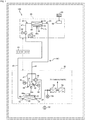
- Fig. 1 is a system diagram of an air-conditioner 100 according to a first embodiment of the present invention.
- the air-conditioner 100 is provided with an outdoor unit 30, an indoor unit 60, and a control device 20 for controlling the units.
- the indoor unit 60 sets an operation mode (such as cooling, heating, dehumidification, or ventilation), an indoor air volume (such as rapid air, strong air, or weak air), a target indoor temperature and the like, in accordance with signals input from a remote controller 90.
- the control device 20 is provided with hardware as a general computer, including a central processing unit (CPU), a digital signal processor (DSP), a random-access memory (RAM), and a read only memory (ROM).
- CPU central processing unit
- DSP digital signal processor
- RAM random-access memory
- ROM read only memory
- a control program executed by the CPU and various data and the like are stored.
- the control device 20 controls various portions of the outdoor unit 30 and the indoor unit 60 based on the control program. The details thereof will be described later.
- the outdoor unit 30 is provided with a compressor 32, a four-way switching valve 34, and an outdoor heat exchanger 36.
- the compressor 32 is provided with a motor 32a, and has the function of compressing a refrigerant that flows in via the four-way switching valve 34.
- a pipe a1 is installed with a suction-side temperature sensor 41 for detecting the temperature of the refrigerant suctioned into the compressor 32, and a suction-side pressure sensor 45 for detecting the pressure of the refrigerant suctioned into the compressor 32.
- a pipe a2 is installed with a discharge-side temperature sensor 42 for detecting the temperature of the refrigerant discharged from the compressor 32, and a discharge-side pressure sensor 46 for detecting the pressure of the refrigerant discharged from the compressor 32.
- the compressor 32 is fitted with a compressor temperature sensor 43 for detecting the temperature of the compressor 32.
- the four-way switching valve 34 has the function of switching the direction of the refrigerant supplied to the indoor unit 60, depending on whether the indoor heat exchanger 64 is caused to function as an evaporator or as a condenser.
- the four-way switching valve 34 during a cooling operation, for example, is turned to connect pipes a2 and a3 and to connect pipes a1 and a6 along the paths of solid lines.
- the high-temperature, high-pressure refrigerant discharged from the compressor 32 is cooled by the outdoor heat exchanger 36.
- the cooled refrigerant is supplied via a pipe a5 to the indoor unit 60.
- the four-way switching valve 34 When the indoor heat exchanger 64 is caused to function as a condenser, the four-way switching valve 34, during a heating operation, for example, is turned to connect the pipes a2 and a6 and to connect the pipes a1 and a3 along the paths of dashed lines. In this case, the high-temperature, high-pressure refrigerant discharged from the compressor 32 is supplied via the pipes a2 and a6 to the indoor unit 60.
- An outdoor fan 48 is provided with a motor 48a, and delivers air to the outdoor heat exchanger 36.
- the outdoor heat exchanger 36 is a heat exchanger for exchanging heat between the air delivered from the outdoor fan 48 and the refrigerant, and is connected to the compressor 32 via the four-way switching valve 34.
- the outdoor unit 30 is fitted with: an outdoor heat exchanger entrance temperature sensor 51 for detecting the temperature of the air that flows into the outdoor heat exchanger 36; an outdoor heat exchanger refrigerant gas temperature sensor 53 for detecting the temperature of gas-side refrigerant of the outdoor heat exchanger 36; and an outdoor heat exchanger refrigerant liquid temperature sensor 55 for detecting the temperature of liquid-side refrigerant of the outdoor heat exchanger 36.
- a power supply unit 54 receives a three-phase alternating-current voltage from a commercial power supply 22.
- a power measurement unit 58 is connected to the power supply unit 54 to measure power consumption by the air-conditioner 100.
- the power supply unit 54 outputs a direct-current voltage that is supplied to a motor controller 56.
- the motor controller 56 is provided with an inverter (not illustrated), and supplies an alternating-current voltage to the motor 32a of the compressor 32 and the motor 48a of the outdoor fan 48.
- the motor controller 56 also controls the motors 32a and 48a in a sensorless manner to thereby detect the rotating speed of the motors 32a and 48a.
- the indoor unit 60 is provided with: an indoor expansion valve 62; an indoor heat exchanger 64; an indoor fan 66; a motor controller 67; and a remote controller communication unit 68 for performing bi-directional communication with the remote controller 90.
- the indoor fan 66 is provided with a motor 66a and delivers air to the indoor heat exchanger 64.
- the motor controller 67 is provided with an inverter (not illustrated) and supplies an alternating-current voltage to the motor 66a.
- the motor controller 67 also controls the motor 66a in a sensorless manner to thereby detect the rotating speed of the motor 66a.
- the indoor expansion valve 62 is inserted between pipes a5 and a7, and has the function of adjusting the flow volume of the refrigerant flowing through the pipes a5 and a7 and reducing the pressure of the refrigerant on the secondary side of the indoor expansion valve 62.
- the indoor heat exchanger 64 is a heat exchanger for exchanging heat between indoor air delivered from the indoor fan 66 and the refrigerant, and is connected to the indoor expansion valve 62 via a pipe a7.
- the indoor unit 60 is also provided with: an indoor heat exchanger entry air temperature sensor 70 (air state sensor); an indoor heat exchanger discharge air temperature sensor 72; an indoor heat exchanger entry humidity sensor 74; an indoor heat exchanger refrigerant liquid temperature sensor 25; and an indoor heat exchanger refrigerant gas temperature sensor 26.
- the indoor heat exchanger entry air temperature sensor 70 detects the temperature of the air drawn by the indoor fan 66.
- the indoor heat exchanger discharge air temperature sensor 72 detects the temperature of the air discharged from the indoor heat exchanger 64.
- the indoor heat exchanger entry humidity sensor 74 detects the humidity of the air drawn by the indoor fan 66.
- the indoor heat exchanger refrigerant liquid temperature sensor 25 and the indoor heat exchanger refrigerant gas temperature sensor 26 are disposed where the indoor heat exchanger 64 and the pipe a6 are connected, and detect the temperature of the refrigerant flowing through the connection.
- the compressor 32, the four-way switching valve 34, the outdoor heat exchanger 36, the indoor expansion valve 62, the indoor heat exchanger 64, and the pipes a1 to a7 form a refrigeration cycle RC.
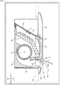
- Fig. 2 is a side cross-sectional view of the indoor unit 60.
- the indoor unit 60 is of a so-called "ceiling cassette-type" that is embedded in a ceiling 130, with a lower surface exposed in the air-conditioned room.
- the indoor heat exchanger 64 is formed as a plate bent in substantially V-shape, and is installed in a central part of the indoor unit 60.
- the indoor fan 66 has fins arranged in a substantially cylindrical shape, and is disposed forwardly of the indoor heat exchanger 64.
- a drain pan 140 for receiving dew-condensed water is disposed under the indoor heat exchanger 64 and the indoor fan 66.
- an inclined air filter 142 is disposed to the rear of the indoor heat exchanger 64.
- the lower surface of the indoor unit 60 is covered with a decorative plate 143.
- An air intake opening 144 is formed by slitting the decorative plate 143 under the air filter 142.
- the indoor heat exchanger entry air temperature sensor 70 is disposed between the indoor heat exchanger 64 and the air filter 142.
- an air blow-out passageway 146 is formed.
- a horizontal deflector 148 is disposed at a point along the air blow-out passageway 146, and controls the direction of air flow in the horizontal direction (perpendicular to the sheet).
- a vertical deflector 150 is disposed at the exit portion of the air blow-out passageway 146, and pivots about a support point 150a to control the direction of air flow in the vertical direction.
- the horizontal deflector 148 and the vertical deflector 150 are pivotally driven by the control device 20 (see Fig. 1 ).
- the vertical deflector 150 indicated by solid lines indicates its position in fully open state.
- the vertical deflector 150 When the air-conditioner 100 is at rest, the vertical deflector 150 is pivoted to a fully closed position 152 indicated by dashed and single-dotted lines. When a washing operation is performed, as will be described later, the vertical deflector 150 is pivoted to a position 156 indicated by dashed and single-dotted line, and is thereafter pivoted to a washing operation position 154. As the degree of opening of the vertical deflector 150 increases, the duct resistance of the air blow-out passageway 146 becomes smaller. However, even when the vertical deflector 150 is closed at the fully closed position 152, there is a gap FS formed between the vertical deflector 150 and the decorative plate 143, so that a small amount of air can flow through the gap FS.
- a "washing operation” is performed automatically or by a user's instruction.
- the “washing operation” refers to an operation for causing frost formation or dew condensation on the surface of the indoor heat exchanger 64, and washing the surface of the indoor heat exchanger 64 using water due to the frost formation or condensation.
- the washing operation is performed automatically when, for example, a setting is made to perform the washing operation periodically at predetermined time intervals.
- the washing operation is classified into a "frozen washing operation” and a "dew condensation washing operation”.
- the control device 20 turns the four-way switching valve 34 in the direction indicated by solid line so that the indoor heat exchanger 64 becomes an evaporator. Then, the control device 20 sets the state of each of the portions of the air-conditioner 100, such as the rotating speed of the compressor 32, the degree of opening of the indoor expansion valve 62, and the rotating speed of the indoor fan 66 so that the surface temperature of the indoor heat exchanger 64 becomes below zero. As this state is continued, frost forms on the surface of the indoor heat exchanger 64.
- the control device 20 turns the four-way switching valve 34 in the direction indicated by dashed line so that the indoor heat exchanger 64 becomes a condenser, and heats the indoor heat exchanger 64. Thereby, the frost attached to the indoor heat exchanger 64 melts, rinsing the surface of the indoor heat exchanger 64.
- the control device 20 keeps heating the indoor heat exchanger 64 for a while thereafter, and keeps driving the indoor fan 66. As a result, the surface of the indoor heat exchanger 64 becomes dry. Through the above steps, the frozen washing operation comes to an end.
- the control device 20 (see Fig. 1 ) also turns the four-way switching valve 34 in the direction indicated by solid line so that the indoor heat exchanger 64 becomes an evaporator.
- the control device 20 sets the state of each of the various parts of the air-conditioner 100 so that the surface temperature of the indoor heat exchanger 64 becomes lower than a dew-point temperature and higher than zero. As this state is continued, dew condensation occurs on the surface of the indoor heat exchanger 64, and the water due to the condensation rinses the surface of the indoor heat exchanger 64.
- control device 20 turns the four-way switching valve 34 in the direction indicated by dashed line so that the indoor heat exchanger 64 becomes a condenser, and keeps heating the indoor heat exchanger 64 and driving the indoor fan 66. In this way, the surface of the indoor heat exchanger 64 becomes dry.
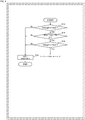
- Fig. 3 is a flowchart of a washing operation process routine in the present embodiment.
- the present routine is performed when the user has entered on the remote controller 90 a command for performing the washing operation, or by the user's instruction when it is the time to perform an automatic operation of the washing operation.
- the vertical deflector 150 is opened to the position 156 indicated in Fig. 2 .
- step S102 rotational driving of the indoor fan 66 is started.
- step S104 the process stands by for a predetermined time.
- the predetermined time is a time for the temperature and humidity around the indoor heat exchanger entry air temperature sensor 70 (see Fig. 2 ) and the indoor heat exchanger entry humidity sensor 74 to become close to the temperature and humidity of the air-conditioned room.
- the predetermined time may be 30 seconds or more and 5 minutes or less, for example.
- the process diverges based on the range of relative humidity H that is the detection result from the indoor heat exchanger entry humidity sensor 74. More specifically, the process diverges based on the result of comparison between the relative humidity H and constants H10, H12, H14, and H16.
- the constants have the relationship "H10 ⁇ H12 ⁇ H14 ⁇ H16", wherein the constants H12, H14 are the minimum value and the maximum value of the relative humidity considered to be preferable for the frozen washing operation.
- the relative humidity H is lower than the constant H12, the relative humidity H is too low so that, even if the frozen washing operation were to be attempted, a sufficient amount of frost would not be formed on the indoor heat exchanger 64 and a sufficient washing effect would not be obtained. If the relative humidity H is too high, if the frozen washing operation were to be attempted, dew condensation may occur at locations other than the indoor heat exchanger 64. For example, if dew condensation occurs on the indoor fan 66 or the air blow-out passageway 146, the problem that the dew-condensed water leaks into the air-conditioned room via the air blow-out passageway 146 may arise.
- the constant H 14 is the value of the relative humidity H such that a dew condensation caused in locations other than the indoor heat exchanger 64 would be less of a problem.
- the range in which the relative humidity H is "H12 ⁇ H ⁇ H14" is a range that is preferable for performing the frozen washing operation.
- the constant H10 is a relative humidity at which it is considered difficult to produce, by dew condensation on the indoor heat exchanger 64, a sufficient amount of water for performing the dew condensation washing operation.
- the constant H16 is a relative humidity at which dew condensation may possibly occur at locations other than the indoor heat exchanger 64 when the dew condensation washing operation were to be attempted.
- step S106 if the relative humidity H is in the range "H12 ⁇ H ⁇ H14", the process proceeds to step S110. If the relative humidity H is in the range “H10 ⁇ H ⁇ H12" or “H14 ⁇ H ⁇ H16”, the process proceeds to step S120. If the relative humidity H is in the range "Other”, i.e., "H ⁇ H10” or "H16 ⁇ H", the process proceeds to step S130.
- step S110 the process diverges based on the range of room temperature T that is the detection result from the indoor heat exchanger entry air temperature sensor 70. More specifically, the process diverges based on the result of comparison between the room temperature T and constants T10, T12, T14, and T16.
- the constants have the relationship "T10 ⁇ T12 ⁇ T14 ⁇ T16".
- step S112 in which a "frozen washing operation F1" is performed. If the room temperature T is in the range "T12 ⁇ T ⁇ T14”, the process proceeds to step S114 in which a "frozen washing operation F2" is performed. If the room temperature T is in the range "T14 ⁇ T ⁇ T16”, the process proceeds to step S116 in which a "frozen washing operation F3" is performed. In the other cases, i.e., if the room temperature T is lower than the constant T10 or higher than T16, the process proceeds to step S130.
- the constant T10 is a value in the vicinity of 0°C, such as a value on the order of 1°C to 6°C.
- the drain pan 140 (see Fig. 2 ) of the indoor unit 60 is fitted with a drain pipe, a drain pump and the like (not illustrated) for discharging dew condensation water. If a location arises where the temperature of the dew condensation water is 0°C or lower, the drain pipe and the like may become clogged at that location. Accordingly, the constant T10 is set to a value on the order of 1°C to 6°C with some margin with respect to "0°C", so that, when the room temperature T has become lower than the constant T10, the washing operation can be cancelled.
- the constant T16 may be set to a temperature at which sufficient frost formation can be caused on the indoor heat exchanger 64.
- the frozen washing operations F1, F2, and F3 have their operation contents set so that the cooling capacity increases as the range of room temperature T becomes higher. More particularly, when the compressor 32 (see Fig. 1 ) during the frozen washing operations F1, F2, and F3 respectively has rotating speeds NF1, NF2, and NF3, the rotating speeds have the relationship "NF1 ⁇ NF2 ⁇ NF3". During each of the frozen washing operations F1, F2, and F3, the control device 20 sets the position of the vertical deflector 150 to the washing operation position 154 (see Fig. 2 ).
- step S120 the process diverges based on the range of room temperature T. More specifically, the process diverges based on the result of comparison between the room temperature T and constants T20, T22, T24, and T26.
- the constants have the relationship "T20 ⁇ T22 ⁇ T24 ⁇ T26".
- step S122 the process proceeds to step S122 in which a "dew condensation washing operation C1" is performed. If the room temperature T is in the range "T22 ⁇ T ⁇ T24", the process proceeds to step S124 in which a "dew condensation washing operation C2" is performed. If the room temperature T is in the range "T24 ⁇ T ⁇ T26”, the process proceeds to step S126 in which a "dew condensation washing operation C3" is performed. In the other cases, i.e., if the room temperature T is lower than the constant T20 or higher than T26, the process proceeds to step S130.
- the constant T20 similarly to the constant T10 described above, is a value on the order of 1°C to 6°C, for example.
- the constant T20 may be the same as constant T10.
- the constant T26 may be set to a temperature such that sufficient dew condensation can be caused on the indoor heat exchanger 64. Accordingly, the constant T26 may preferably be higher than the constant T16 described above.
- the dew condensation washing operations C1, C2, and C3 have their operation contents set so that the cooling capacity increases as the range of room temperature T becomes higher. More particularly, when the compressor 32 (see Fig. 1 ) during the dew condensation washing operations C1, C2, and C3 respectively has rotating speeds NC1, NC2, and NC3, the rotating speeds have the relationship "NC1 ⁇ NC2 ⁇ NC3". Further, because the dew condensation washing operation lowers the cooling capacity compared to the frozen washing operation, the rotating speeds, when combined with the rotating speeds NF1, NF2, and NF3 during the frozen washing operation described above, have the relationship "NC1 ⁇ NC2 ⁇ NC3 ⁇ NF1 ⁇ NF2 ⁇ NF3". In each of the dew condensation washing operations C1, C2, and C3, the control device 20 sets the position of the vertical deflector 150 to the washing operation position 154 (see Fig. 2 ).
- step S130 the control device 20 performs a washing operation shut-down process. That is, the control device 20 shuts down the refrigeration cycle RC, shuts down the indoor fan 66, and causes the vertical deflector 150 to pivot to the fully closed position 152 (see Fig. 2 ). If "Other" has been determined in any of the steps S106, S110, and S120, neither the frozen washing operation nor the dew condensation washing operation are performed, and the shut-down process of step S130 is performed. Thus, the process of the present routine ends.
- an operation called “watch-over operation” is also performed.
- a “watch-over operation” refers to performing a cooling operation automatically when the temperature of the air-conditioned room has become a predetermined temperature or above.
- the control device 20 upon instruction from the user via the remote controller 90 to perform the "watch-over operation", the control device 20, in the period in which the refrigeration cycle RC is shut down, performs a "room temperature acquisition process" at predetermined monitoring periodic intervals.
- the “room temperature acquisition process” refers to taking the air in the air-conditioned room into the indoor unit 60 by driving the indoor fan 66 for a predetermined time, and acquiring the detection result from the indoor heat exchanger entry air temperature sensor 70 as the room temperature T.
- the control device 20 determines whether the acquired room temperature T is higher than or equal to a predetermined temperature and, if the determination result is "Yes", performs cooling operation.
- the "room temperature acquisition process" during the “watch-over operation” is similar to the process of steps S101, S102, S104, and S106 of the washing operation (see Fig. 3 ) in that the indoor fan 66 is driven to take the air in the air-conditioned room into the indoor unit 60 and the room temperature T is acquired.
- step S101 of the washing operation the vertical deflector 150 is opened to the position 156 (see Fig. 2 ).
- the "room temperature acquisition process" during the “watch-over operation” differs in that the vertical deflector 150 remains at the fully closed position 152.
- the drive time of the indoor fan 66 (standby time in step S104) during the washing operation is longer than the drive time of the indoor fan 66 during the room temperature acquisition process of the watch-over operation.
- the rotating speed of the indoor fan 66 (rotating speed in step S104) during the washing operation is higher than the rotating speed of the indoor fan 66 during the room temperature acquisition process of the watch-over operation.
- the process of steps S101 to S106 during the washing operation differs from the room temperature acquisition process of the watch-over operation in that the degree of opening of the vertical deflector 150 is greater, the drive time of the indoor fan 66 is longer, and the rotating speed of the indoor fan 66 is higher.
- One of the reasons for such differences is that during the room temperature acquisition process of the watch-over operation, only the room temperature T needs to be acquired, and it is not necessary to measure the relative humidity H.
- the control device (20) has the function (S102, S104) of driving the indoor fan (66) for a predetermined time before performing the washing operation, and the function (S110, S120) of performing the washing operation on condition that the detection result from the air state sensor (70, 74) after the indoor fan (66) has been driven is within a first predetermined range.
- the detection result from the air state sensor (70, 74) can be made accurate, and the washing operation can be performed appropriately.
- the predetermined time is a time greater than or equal to 30 seconds, and, even when it is being determined whether the detection result from the air state sensor (70, 74) is within the first predetermined range, the driving of the indoor fan (66) is continued. This makes it possible to make the detection result from the air state sensor (70, 74) even more accurate, and the washing operation can be performed even more appropriately.
- the control device (20) further has the function (S101) of placing the vertical deflector (150) in a state more open than the closed state in a predetermined period of time. This makes it possible to promote the flow of air through the air-conditioner (100), make the detection result from the air state sensor (70, 74) even more accurate, and perform the washing operation even more appropriately.
- the control device (20) has the watch-over operation function of performing cooling operation automatically in accordance with the detection result from the air state sensor (70, 74) after the indoor fan (66) has been rotated, wherein the rotating speed at which the indoor fan (66) is rotated before the washing operation is performed is higher than the rotating speed at which the indoor fan (66) is rotated before the watch-over operation function is performed.
- the watch-over operation it is possible to make the detection result from the air state sensor (70, 74) even more accurate, so that the washing operation can be performed even more appropriately.
- the control device (20) further has the function (S10, S120) of setting the rotating speed of the compressor (32) based on the detection result from the air state sensor (70, 74) after the indoor fan (66) has been driven.
- the air-conditioner (100) it is possible to provide with an appropriate cooling capacity.
- the control device (20) further has the function (S106) of selecting, based on the detection result from the air state sensor (70, 74) after the indoor fan (66) has been driven, the frozen washing operation for causing frost formation on the indoor heat exchanger (64), or the dew condensation washing operation for causing dew condensation without causing frost formation on the indoor heat exchanger (64).
- the frozen washing operation for causing frost formation on the indoor heat exchanger (64)
- the dew condensation washing operation for causing dew condensation without causing frost formation on the indoor heat exchanger (64).
- the hardware configuration of the second embodiment is similar to that of the first embodiment (see Fig. 1 and Fig. 2 ). However, in the present embodiment, instead of the washing operation process routine depicted in Fig. 3 , a washing operation process routine depicted in Fig. 4 is performed.
- the present routine is also performed when the user has entered on the remote controller 90 a command for performing the washing operation (see Fig. 1 ), or when it is the time to perform an automatic operation of the washing operation.
- H60 and H62 are predetermined constants.
- the constant H60 is a value slightly lower than the constant H10 discussed in step S106 of Fig. 3 .
- the constant H62 is a value slightly higher than the constant H16 discussed in step S106. That is, the range of the constants H60 to H62 is wider than the range of the constants H10 to H16.
- step S12 If it is determined “Yes” in step S12, the process proceeds to step S14 in which it is determined whether an outside air temperature TD that is the detection result from the outdoor heat exchanger entrance temperature sensor 51 satisfies the condition "TD0 ⁇ TD ⁇ TD2".
- TD0 and TD2 are predetermined constants.
- the constant TD0 similarly to the constants T10 and T20 discussed in steps S110 and S120, is a value in the vicinity of 0°C, such as a value on the order of 1 °C to 6°C. If the outside air temperature is too high, it may be impossible to ensure cooling capacity to such an extent that sufficient frost formation or dew condensation can be caused on the indoor heat exchanger 64.
- the constant TD2 may be set to a temperature at which sufficient frost formation or dew condensation can be caused on the indoor heat exchanger 64.
- step S14 the process proceeds to step S16 in which it is determined whether the room temperature T that is the detection result from the indoor heat exchanger entry air temperature sensor 70 satisfies the condition "T80 ⁇ T ⁇ T82".
- T80 and T82 are predetermined constants.
- the constant T80 is a value in the vicinity of 0°C; the constant T80, however, is set to a value lower than the constants T10 and T20 discussed in steps S110 and S120.
- the constant T82 is set to a value higher than the constant T26 discussed in step S120. That is, the range of the constants T80 to T82 is wider than the range of the constants T10 to T20.
- step S16 If it is determined “Yes” in step S16, the same process as that from step S100 of Fig. 3 is performed. On the other hand, if it is determined “No” in any of steps S12, S14, and S16, the process proceeds to step S20 in which the control device 20 performs the washing operation shut-down process, and the process of the present routine ends.
- the present embodiment further has the function (S12 to S16) of driving the indoor fan (66) on condition that, before driving the indoor fan (66), the detection result from the air state sensor (70, 74) is within a second predetermined range. Further, the second predetermined range is wider than the first predetermined range. Thus, if the detection result from the air state sensor (70, 74) is not within the second predetermined range, no electric power for moving the indoor fan (66) is required, thereby achieving energy conservation.
- step S106, S110, or S120 the shut-down process of step S130 is performed while performing neither the frozen washing operation nor the dew condensation washing operation. In this case, the user might suspect that "a failure has occurred in the air-conditioner (100)". According to the present embodiment, it is possible to increase the probability that the frozen washing operation or the dew condensation washing operation will be performed once the indoor fan (66) has been driven, thus decreasing the frequency with which the user may have a suspicion.
- the hardware configuration of the third embodiment is similar to that of the first embodiment (see Fig. 1 and Fig. 2 ). However, in the present embodiment, instead of the washing operation process routine depicted in Fig. 3 , a washing operation process routine depicted in Fig. 5 is performed. The present routine is also performed when the user has entered on the remote controller 90 a command for performing the washing operation (see Fig. 1 ), or when it is the time to perform an automatic operation of the washing operation.
- the control device 20 performs the process of steps S140, S142, and S144.
- the contents of the steps are the same as those of steps S101, S102, and S104 (see Fig. 3 ) in the first embodiment.
- the process diverges based on the range of room temperature T that is the detection result from the indoor heat exchanger entry air temperature sensor 70. More specifically, the process diverges based on the result of comparison between the room temperature T and constants T50, T52, T54, T56, T58, T60, and T62.
- the constants have the relationship "T50 ⁇ T52 ⁇ T54 ⁇ T56 ⁇ T58 ⁇ T60 ⁇ T62".
- step S152 the process proceeds to step S152 in which a "dew condensation washing operation C1" is performed. If the room temperature T is in the range "T52 ⁇ T ⁇ T54”, the process proceeds to step S154 in which a "dew condensation washing operation C2" is performed. If the room temperature T is in the range "T54 ⁇ T ⁇ T56", the process proceeds to step S156 in which a "frozen washing operation F1" is performed.
- step S158 in which a "frozen washing operation F2" is performed. If the room temperature T is in the range "T58 ⁇ T ⁇ T60”, the process proceeds to step S160 in which a "frozen washing operation F3" is performed. If the room temperature T is in the range "T60 ⁇ T ⁇ T62”, the process proceeds to step S162 in which a "dew condensation washing operation C3" is performed. In the other cases, i.e., if the room temperature T is lower than the constant T50 or higher than T62, the process proceeds to step S170.
- step S170 in which the control device 20 performs the washing operation shut-down process.
- the content of the shut-down process is the same as that of step S130 (see Fig. 3 ) of the first embodiment wherein the control device 20 shuts down the refrigeration cycle RC, also shuts down the indoor fan 66, and causes the vertical deflector 150 to pivot to the fully closed position 152 (see Fig. 2 ). If it is determined "Other" in step S150 described above, the frozen washing operation or the dew condensation washing operation is not performed, and the shut-down process of step S170 is performed. Thus, the process of the present routine ends.
- the determination based on relative humidity is not made. This is because temperature and relative humidity have a correlation depending on the region in which the air-conditioner 100 is installed. For example, assume that the air-conditioner 100 is set for Japan. The climate of Japan in such that the temperature tends to become low in winter and high in summer. At the same time, the relative humidity tends to become low in winter and high in summer. This means that the relative humidity has a monotonically increasing correlation with respect to the temperature.
- the control device 20 performs the frozen washing operations F1 to F3. If the room temperature T is in the lower or upper ranges "T50 ⁇ T ⁇ T54" or "T60 ⁇ T ⁇ T62", it can be inferred that the relative humidity H will also be in a preferable range for the dew condensation washing operation, and so the control device 20 performs the dew condensation washing operations C1 to C3.
- the detection result from the indoor heat exchanger entry air temperature sensor 70 it is possible to make the detection result from the indoor heat exchanger entry air temperature sensor 70 accurate, and the washing operation can be performed appropriately. Further, in the process of steps S1 40 to S170 in the present embodiment, the determination based on relative humidity is not performed. Accordingly, it is possible to omit the indoor heat exchanger entry humidity sensor 74 depicted in Fig. 1 and Fig. 2 , and to reduce costs for the air-conditioner 100.
- step S140 before the process of step S140 is performed, the same process as that of steps S14, S16, and S20 may be performed. That is, if it is determined “Yes” in both steps S14 and S16, the process of step S140 and the subsequent steps may be performed. If it is determined “No” in step S14 or S16, the shut-down process of step S20 may be performed.
- the present invention is not limited to the foregoing embodiments and may include various modifications.
- the foregoing embodiments have been described by way of example to facilitate an understanding of the present invention, and are not necessarily limited to those provided with all of the configurations described. Some of the configurations of one embodiment may be substituted by a configuration of another embodiment, or a configuration of the other embodiment may be incorporated into a configuration of one embodiment. With respect to some of the configurations of each of the embodiments, deletion, addition, or substitution of other configurations may be made.
- the control lines or information lines depicted in the drawings are those considered necessary for illustrative purposes, and do not necessarily represent all of the control lines or information lines required in a product. It may be considered that in practice, most of the configurations are interconnected. Modifications that may be made with respect to the foregoing embodiments include the following.
Landscapes
- Engineering & Computer Science (AREA)
- Chemical & Material Sciences (AREA)
- Combustion & Propulsion (AREA)
- Mechanical Engineering (AREA)
- General Engineering & Computer Science (AREA)
- Physics & Mathematics (AREA)
- Fluid Mechanics (AREA)
- Human Computer Interaction (AREA)
- Air Conditioning Control Device (AREA)
Abstract
Description
- The present invention relates to an air-conditioner, a method of controlling an air-conditioner, and a program.
- With regard to a washing operation for an air-conditioner, Patent Literature 1 indicated below describes that "An air-conditioner is provided with: a refrigeration cycle including a heat exchanger for cooling or heating ambient air; and a
control device 130 that can perform a heating operation, a cooling operation, a dehumidification operation and the like, and controls the refrigeration cycle to perform a washing operation for washing the surface of the heat exchanger. Here, thecontrol device 130 includes a regulating controller 138 that regulates the performing of the washing operation when a predetermined condition arises" (see Abstract). - Patent Literature 1 also describes that, with respect to the sensing of temperature in an air-conditioned room, i.e., the interior space in which an indoor unit is installed, "the room temperature sensing unit 161 senses the temperature of the inside of an air-conditioned room, and is preferably adapted to detect, using a far-infrared sensor, such as a thermopile, the room temperature of an area equivalent to an area captured by an
image capture unit 110" (see the Description, paragraph 0020). - Patent Literature 1:
JP-A-6296633 - Generally, the indoor unit of an air-conditioner has a plurality of sensors, and, as described in Patent Literature 1, one of the sensors may sometimes be applied as a sensor for detecting the state of the air-conditioned room. However, depending on the status of the indoor unit, the discrepancy between the measurement result from the sensor and the actual state of the air-conditioned room may become large, possibly resulting in an inability to perform the washing operation appropriately.
- The present invention has been made in view of the above circumstances, and an object of the present invention is to provide an air-conditioner that can perform a washing operation appropriately, a method of controlling an air-conditioner, and a program.
- In order to solve the problem, an air-conditioner of the present invention includes: a refrigeration cycle including a compressor for compressing a refrigerant, and an indoor heat exchanger for cooling or heating air in an air-conditioned room; a control device for controlling the refrigeration cycle to perform a washing operation for washing a surface of the indoor heat exchanger; an indoor fan for delivering air to the indoor heat exchanger; and an air state sensor for detecting a temperature or humidity of air that flows in from the air-conditioned room. The control device includes: a function of driving the indoor fan for a predetermined time before performing the washing operation; and a function of allowing the washing operation to be performed on condition that a detection result from the air state sensor after the indoor fan has been driven is within a first predetermined range.
- According to the present invention, a washing operation can be performed appropriately.
-
-
Fig. 1 is a system diagram of an air-conditioner 100 according to a first embodiment of the present invention. -
Fig. 2 is a side cross-sectional view of an indoor unit according to the first embodiment. -
Fig. 3 is a flowchart of a washing operation process routine in the first embodiment. -
Fig. 4 is a flowchart of a washing operation process routine according to a second embodiment. -
Fig. 5 is a flowchart of a washing operation process routine according to a third embodiment. -
Fig. 1 is a system diagram of an air-conditioner 100 according to a first embodiment of the present invention. - The air-
conditioner 100 is provided with anoutdoor unit 30, anindoor unit 60, and acontrol device 20 for controlling the units. Theindoor unit 60 sets an operation mode (such as cooling, heating, dehumidification, or ventilation), an indoor air volume (such as rapid air, strong air, or weak air), a target indoor temperature and the like, in accordance with signals input from aremote controller 90. - The
control device 20 is provided with hardware as a general computer, including a central processing unit (CPU), a digital signal processor (DSP), a random-access memory (RAM), and a read only memory (ROM). In the ROM, a control program executed by the CPU and various data and the like are stored. Thecontrol device 20 controls various portions of theoutdoor unit 30 and theindoor unit 60 based on the control program. The details thereof will be described later. - The
outdoor unit 30 is provided with acompressor 32, a four-way switching valve 34, and anoutdoor heat exchanger 36. Thecompressor 32 is provided with amotor 32a, and has the function of compressing a refrigerant that flows in via the four-way switching valve 34. A pipe a1 is installed with a suction-side temperature sensor 41 for detecting the temperature of the refrigerant suctioned into thecompressor 32, and a suction-side pressure sensor 45 for detecting the pressure of the refrigerant suctioned into thecompressor 32. A pipe a2 is installed with a discharge-side temperature sensor 42 for detecting the temperature of the refrigerant discharged from thecompressor 32, and a discharge-side pressure sensor 46 for detecting the pressure of the refrigerant discharged from thecompressor 32. Thecompressor 32 is fitted with a compressor temperature sensor 43 for detecting the temperature of thecompressor 32. - The four-
way switching valve 34 has the function of switching the direction of the refrigerant supplied to theindoor unit 60, depending on whether theindoor heat exchanger 64 is caused to function as an evaporator or as a condenser. When theindoor heat exchanger 64 is caused to function as an evaporator, the four-way switching valve 34, during a cooling operation, for example, is turned to connect pipes a2 and a3 and to connect pipes a1 and a6 along the paths of solid lines. In this case, the high-temperature, high-pressure refrigerant discharged from thecompressor 32 is cooled by theoutdoor heat exchanger 36. The cooled refrigerant is supplied via a pipe a5 to theindoor unit 60. - When the
indoor heat exchanger 64 is caused to function as a condenser, the four-way switching valve 34, during a heating operation, for example, is turned to connect the pipes a2 and a6 and to connect the pipes a1 and a3 along the paths of dashed lines. In this case, the high-temperature, high-pressure refrigerant discharged from thecompressor 32 is supplied via the pipes a2 and a6 to theindoor unit 60. Anoutdoor fan 48 is provided with amotor 48a, and delivers air to theoutdoor heat exchanger 36. - The
outdoor heat exchanger 36 is a heat exchanger for exchanging heat between the air delivered from theoutdoor fan 48 and the refrigerant, and is connected to thecompressor 32 via the four-way switching valve 34. Theoutdoor unit 30 is fitted with: an outdoor heat exchangerentrance temperature sensor 51 for detecting the temperature of the air that flows into theoutdoor heat exchanger 36; an outdoor heat exchanger refrigerantgas temperature sensor 53 for detecting the temperature of gas-side refrigerant of theoutdoor heat exchanger 36; and an outdoor heat exchanger refrigerantliquid temperature sensor 55 for detecting the temperature of liquid-side refrigerant of theoutdoor heat exchanger 36. - A
power supply unit 54 receives a three-phase alternating-current voltage from acommercial power supply 22. Apower measurement unit 58 is connected to thepower supply unit 54 to measure power consumption by the air-conditioner 100. Thepower supply unit 54 outputs a direct-current voltage that is supplied to amotor controller 56. Themotor controller 56 is provided with an inverter (not illustrated), and supplies an alternating-current voltage to themotor 32a of thecompressor 32 and themotor 48a of theoutdoor fan 48. Themotor controller 56 also controls themotors motors - The
indoor unit 60 is provided with: anindoor expansion valve 62; anindoor heat exchanger 64; anindoor fan 66; amotor controller 67; and a remote controller communication unit 68 for performing bi-directional communication with theremote controller 90. Theindoor fan 66 is provided with amotor 66a and delivers air to theindoor heat exchanger 64. Themotor controller 67 is provided with an inverter (not illustrated) and supplies an alternating-current voltage to themotor 66a. Themotor controller 67 also controls themotor 66a in a sensorless manner to thereby detect the rotating speed of themotor 66a. - The
indoor expansion valve 62 is inserted between pipes a5 and a7, and has the function of adjusting the flow volume of the refrigerant flowing through the pipes a5 and a7 and reducing the pressure of the refrigerant on the secondary side of theindoor expansion valve 62. Theindoor heat exchanger 64 is a heat exchanger for exchanging heat between indoor air delivered from theindoor fan 66 and the refrigerant, and is connected to theindoor expansion valve 62 via a pipe a7. - The
indoor unit 60 is also provided with: an indoor heat exchanger entry air temperature sensor 70 (air state sensor); an indoor heat exchanger dischargeair temperature sensor 72; an indoor heat exchanger entry humidity sensor 74; an indoor heat exchanger refrigerantliquid temperature sensor 25; and an indoor heat exchanger refrigerantgas temperature sensor 26. - The indoor heat exchanger entry
air temperature sensor 70 detects the temperature of the air drawn by theindoor fan 66. The indoor heat exchanger dischargeair temperature sensor 72 detects the temperature of the air discharged from theindoor heat exchanger 64. - The indoor heat exchanger entry humidity sensor 74 (air state sensor) detects the humidity of the air drawn by the
indoor fan 66. The indoor heat exchanger refrigerantliquid temperature sensor 25 and the indoor heat exchanger refrigerantgas temperature sensor 26 are disposed where theindoor heat exchanger 64 and the pipe a6 are connected, and detect the temperature of the refrigerant flowing through the connection. Thus, thecompressor 32, the four-way switching valve 34, theoutdoor heat exchanger 36, theindoor expansion valve 62, theindoor heat exchanger 64, and the pipes a1 to a7 form a refrigeration cycle RC. -
Fig. 2 is a side cross-sectional view of theindoor unit 60. Theindoor unit 60 is of a so-called "ceiling cassette-type" that is embedded in aceiling 130, with a lower surface exposed in the air-conditioned room. - Referring to
Fig. 2 , theindoor heat exchanger 64 is formed as a plate bent in substantially V-shape, and is installed in a central part of theindoor unit 60. Theindoor fan 66 has fins arranged in a substantially cylindrical shape, and is disposed forwardly of theindoor heat exchanger 64. Adrain pan 140 for receiving dew-condensed water is disposed under theindoor heat exchanger 64 and theindoor fan 66. - To the rear of the
indoor heat exchanger 64, aninclined air filter 142 is disposed. The lower surface of theindoor unit 60 is covered with adecorative plate 143. Anair intake opening 144 is formed by slitting thedecorative plate 143 under theair filter 142. The indoor heat exchanger entryair temperature sensor 70 is disposed between theindoor heat exchanger 64 and theair filter 142. - To the front of the
indoor fan 66, an air blow-outpassageway 146 is formed. Ahorizontal deflector 148 is disposed at a point along the air blow-outpassageway 146, and controls the direction of air flow in the horizontal direction (perpendicular to the sheet). Avertical deflector 150 is disposed at the exit portion of the air blow-outpassageway 146, and pivots about asupport point 150a to control the direction of air flow in the vertical direction. Thehorizontal deflector 148 and thevertical deflector 150 are pivotally driven by the control device 20 (seeFig. 1 ). InFig. 2 , thevertical deflector 150 indicated by solid lines indicates its position in fully open state. - When the air-
conditioner 100 is at rest, thevertical deflector 150 is pivoted to a fullyclosed position 152 indicated by dashed and single-dotted lines. When a washing operation is performed, as will be described later, thevertical deflector 150 is pivoted to aposition 156 indicated by dashed and single-dotted line, and is thereafter pivoted to awashing operation position 154. As the degree of opening of thevertical deflector 150 increases, the duct resistance of the air blow-outpassageway 146 becomes smaller. However, even when thevertical deflector 150 is closed at the fullyclosed position 152, there is a gap FS formed between thevertical deflector 150 and thedecorative plate 143, so that a small amount of air can flow through the gap FS. - The operation of the present embodiment will be described.
- In the present embodiment, a "washing operation" is performed automatically or by a user's instruction. The "washing operation" refers to an operation for causing frost formation or dew condensation on the surface of the
indoor heat exchanger 64, and washing the surface of theindoor heat exchanger 64 using water due to the frost formation or condensation. The washing operation is performed automatically when, for example, a setting is made to perform the washing operation periodically at predetermined time intervals. The washing operation is classified into a "frozen washing operation" and a "dew condensation washing operation". - In the frozen washing operation, the control device 20 (see
Fig. 1 ) turns the four-way switching valve 34 in the direction indicated by solid line so that theindoor heat exchanger 64 becomes an evaporator. Then, thecontrol device 20 sets the state of each of the portions of the air-conditioner 100, such as the rotating speed of thecompressor 32, the degree of opening of theindoor expansion valve 62, and the rotating speed of theindoor fan 66 so that the surface temperature of theindoor heat exchanger 64 becomes below zero. As this state is continued, frost forms on the surface of theindoor heat exchanger 64. - Next, the
control device 20 turns the four-way switching valve 34 in the direction indicated by dashed line so that theindoor heat exchanger 64 becomes a condenser, and heats theindoor heat exchanger 64. Thereby, the frost attached to theindoor heat exchanger 64 melts, rinsing the surface of theindoor heat exchanger 64. Thecontrol device 20 keeps heating theindoor heat exchanger 64 for a while thereafter, and keeps driving theindoor fan 66. As a result, the surface of theindoor heat exchanger 64 becomes dry. Through the above steps, the frozen washing operation comes to an end. - During the dew condensation washing operation, the control device 20 (see
Fig. 1 ) also turns the four-way switching valve 34 in the direction indicated by solid line so that theindoor heat exchanger 64 becomes an evaporator. Next, thecontrol device 20 sets the state of each of the various parts of the air-conditioner 100 so that the surface temperature of theindoor heat exchanger 64 becomes lower than a dew-point temperature and higher than zero. As this state is continued, dew condensation occurs on the surface of theindoor heat exchanger 64, and the water due to the condensation rinses the surface of theindoor heat exchanger 64. Thereafter, thecontrol device 20 turns the four-way switching valve 34 in the direction indicated by dashed line so that theindoor heat exchanger 64 becomes a condenser, and keeps heating theindoor heat exchanger 64 and driving theindoor fan 66. In this way, the surface of theindoor heat exchanger 64 becomes dry. Through the above steps, the dew condensation washing operation comes to an end. -
Fig. 3 is a flowchart of a washing operation process routine in the present embodiment. - The present routine is performed when the user has entered on the remote controller 90 a command for performing the washing operation, or by the user's instruction when it is the time to perform an automatic operation of the washing operation.
- Referring to
Fig. 3 , as the process proceeds to step S101, thevertical deflector 150 is opened to theposition 156 indicated inFig. 2 . As the process proceeds to step S102, rotational driving of theindoor fan 66 is started. As the process proceeds to step S104, the process stands by for a predetermined time. The predetermined time is a time for the temperature and humidity around the indoor heat exchanger entry air temperature sensor 70 (seeFig. 2 ) and the indoor heat exchanger entry humidity sensor 74 to become close to the temperature and humidity of the air-conditioned room. The predetermined time may be 30 seconds or more and 5 minutes or less, for example. - After the elapse of the predetermined time, as the process proceeds to step S106, the process diverges based on the range of relative humidity H that is the detection result from the indoor heat exchanger entry humidity sensor 74. More specifically, the process diverges based on the result of comparison between the relative humidity H and constants H10, H12, H14, and H16. The constants have the relationship "H10 < H12 < H14 < H16", wherein the constants H12, H14 are the minimum value and the maximum value of the relative humidity considered to be preferable for the frozen washing operation.
- If the relative humidity H is lower than the constant H12, the relative humidity H is too low so that, even if the frozen washing operation were to be attempted, a sufficient amount of frost would not be formed on the
indoor heat exchanger 64 and a sufficient washing effect would not be obtained. If the relative humidity H is too high, if the frozen washing operation were to be attempted, dew condensation may occur at locations other than theindoor heat exchanger 64. For example, if dew condensation occurs on theindoor fan 66 or the air blow-outpassageway 146, the problem that the dew-condensed water leaks into the air-conditioned room via the air blow-outpassageway 146 may arise. - The
constant H 14 is the value of the relative humidity H such that a dew condensation caused in locations other than theindoor heat exchanger 64 would be less of a problem. In other words, the range in which the relative humidity H is "H12 ≤ H < H14" is a range that is preferable for performing the frozen washing operation. The constant H10 is a relative humidity at which it is considered difficult to produce, by dew condensation on theindoor heat exchanger 64, a sufficient amount of water for performing the dew condensation washing operation. The constant H16 is a relative humidity at which dew condensation may possibly occur at locations other than theindoor heat exchanger 64 when the dew condensation washing operation were to be attempted. - In step S106, if the relative humidity H is in the range "H12 ≤ H < H14", the process proceeds to step S110. If the relative humidity H is in the range "H10 ≤ H < H12" or "H14 ≤ H < H16", the process proceeds to step S120. If the relative humidity H is in the range "Other", i.e., "H < H10" or "H16 ≤ H", the process proceeds to step S130.
- In step S110, the process diverges based on the range of room temperature T that is the detection result from the indoor heat exchanger entry
air temperature sensor 70. More specifically, the process diverges based on the result of comparison between the room temperature T and constants T10, T12, T14, and T16. The constants have the relationship "T10 < T12 < T14 < T16". - If the room temperature T is in the range "T10 ≤ T < T12", the process proceeds to step S112 in which a "frozen washing operation F1" is performed. If the room temperature T is in the range "T12 ≤ T < T14", the process proceeds to step S114 in which a "frozen washing operation F2" is performed. If the room temperature T is in the range "T14 ≤ T < T16", the process proceeds to step S116 in which a "frozen washing operation F3" is performed. In the other cases, i.e., if the room temperature T is lower than the constant T10 or higher than T16, the process proceeds to step S130.
- The constant T10 is a value in the vicinity of 0°C, such as a value on the order of 1°C to 6°C. The drain pan 140 (see
Fig. 2 ) of theindoor unit 60 is fitted with a drain pipe, a drain pump and the like (not illustrated) for discharging dew condensation water. If a location arises where the temperature of the dew condensation water is 0°C or lower, the drain pipe and the like may become clogged at that location. Accordingly, the constant T10 is set to a value on the order of 1°C to 6°C with some margin with respect to "0°C", so that, when the room temperature T has become lower than the constant T10, the washing operation can be cancelled. If the room temperature T is too high, it may be impossible to ensure cooling capacity to such an extent that sufficient frost formation can be caused on theindoor heat exchanger 64. The constant T16 may be set to a temperature at which sufficient frost formation can be caused on theindoor heat exchanger 64. - The frozen washing operations F1, F2, and F3 have their operation contents set so that the cooling capacity increases as the range of room temperature T becomes higher. More particularly, when the compressor 32 (see
Fig. 1 ) during the frozen washing operations F1, F2, and F3 respectively has rotating speeds NF1, NF2, and NF3, the rotating speeds have the relationship "NF1 < NF2 < NF3". During each of the frozen washing operations F1, F2, and F3, thecontrol device 20 sets the position of thevertical deflector 150 to the washing operation position 154 (seeFig. 2 ). - As the process proceeds from step S106 to step S120, the process diverges based on the range of room temperature T. More specifically, the process diverges based on the result of comparison between the room temperature T and constants T20, T22, T24, and T26. The constants have the relationship "T20 < T22 < T24 < T26".
- If the room temperature T is in the range "T20 ≤ T < T22", the process proceeds to step S122 in which a "dew condensation washing operation C1" is performed. If the room temperature T is in the range "T22 ≤ T < T24", the process proceeds to step S124 in which a "dew condensation washing operation C2" is performed. If the room temperature T is in the range "T24 ≤ T < T26", the process proceeds to step S126 in which a "dew condensation washing operation C3" is performed. In the other cases, i.e., if the room temperature T is lower than the constant T20 or higher than T26, the process proceeds to step S130.
- Here, the constant T20, similarly to the constant T10 described above, is a value on the order of 1°C to 6°C, for example. The constant T20 may be the same as constant T10. The constant T26 may be set to a temperature such that sufficient dew condensation can be caused on the
indoor heat exchanger 64. Accordingly, the constant T26 may preferably be higher than the constant T16 described above. - The dew condensation washing operations C1, C2, and C3 have their operation contents set so that the cooling capacity increases as the range of room temperature T becomes higher. More particularly, when the compressor 32 (see
Fig. 1 ) during the dew condensation washing operations C1, C2, and C3 respectively has rotating speeds NC1, NC2, and NC3, the rotating speeds have the relationship "NC1 < NC2 < NC3". Further, because the dew condensation washing operation lowers the cooling capacity compared to the frozen washing operation, the rotating speeds, when combined with the rotating speeds NF1, NF2, and NF3 during the frozen washing operation described above, have the relationship "NC1 < NC2 < NC3 < NF1 < NF2 < NF3". In each of the dew condensation washing operations C1, C2, and C3, thecontrol device 20 sets the position of thevertical deflector 150 to the washing operation position 154 (seeFig. 2 ). - As any of the processes of steps S112 to S116 and S122 to S126 described above comes to an end, the process proceeds to step S130 in which the
control device 20 performs a washing operation shut-down process. That is, thecontrol device 20 shuts down the refrigeration cycle RC, shuts down theindoor fan 66, and causes thevertical deflector 150 to pivot to the fully closed position 152 (seeFig. 2 ). If "Other" has been determined in any of the steps S106, S110, and S120, neither the frozen washing operation nor the dew condensation washing operation are performed, and the shut-down process of step S130 is performed. Thus, the process of the present routine ends. - In the present embodiment, an operation called "watch-over operation" is also performed. In general, a "watch-over operation" refers to performing a cooling operation automatically when the temperature of the air-conditioned room has become a predetermined temperature or above. In the present embodiment, upon instruction from the user via the
remote controller 90 to perform the "watch-over operation", thecontrol device 20, in the period in which the refrigeration cycle RC is shut down, performs a "room temperature acquisition process" at predetermined monitoring periodic intervals. The "room temperature acquisition process" refers to taking the air in the air-conditioned room into theindoor unit 60 by driving theindoor fan 66 for a predetermined time, and acquiring the detection result from the indoor heat exchanger entryair temperature sensor 70 as the room temperature T. Next, thecontrol device 20 determines whether the acquired room temperature T is higher than or equal to a predetermined temperature and, if the determination result is "Yes", performs cooling operation. - Thus, the "room temperature acquisition process" during the "watch-over operation" is similar to the process of steps S101, S102, S104, and S106 of the washing operation (see
Fig. 3 ) in that theindoor fan 66 is driven to take the air in the air-conditioned room into theindoor unit 60 and the room temperature T is acquired. - However, as described above, in step S101 of the washing operation, the
vertical deflector 150 is opened to the position 156 (seeFig. 2 ). The "room temperature acquisition process" during the "watch-over operation" differs in that thevertical deflector 150 remains at the fullyclosed position 152. - Also, the drive time of the indoor fan 66 (standby time in step S104) during the washing operation is longer than the drive time of the
indoor fan 66 during the room temperature acquisition process of the watch-over operation. In addition, the rotating speed of the indoor fan 66 (rotating speed in step S104) during the washing operation is higher than the rotating speed of theindoor fan 66 during the room temperature acquisition process of the watch-over operation. - Thus, the process of steps S101 to S106 during the washing operation differs from the room temperature acquisition process of the watch-over operation in that the degree of opening of the
vertical deflector 150 is greater, the drive time of theindoor fan 66 is longer, and the rotating speed of theindoor fan 66 is higher. One of the reasons for such differences is that during the room temperature acquisition process of the watch-over operation, only the room temperature T needs to be acquired, and it is not necessary to measure the relative humidity H. Particularly, when the inside of theindoor unit 60 is dry, in order to match the relative humidity in theindoor unit 60 with the relative humidity of the air-conditioned room, it is preferable to increase the drive time of theindoor fan 66 compared to when only the temperature is matched. - Thus, according to the present embodiment, the control device (20) has the function (S102, S104) of driving the indoor fan (66) for a predetermined time before performing the washing operation, and the function (S110, S120) of performing the washing operation on condition that the detection result from the air state sensor (70, 74) after the indoor fan (66) has been driven is within a first predetermined range.
- In this way, according to the present embodiment, the detection result from the air state sensor (70, 74) can be made accurate, and the washing operation can be performed appropriately.
- Further, the predetermined time is a time greater than or equal to 30 seconds, and, even when it is being determined whether the detection result from the air state sensor (70, 74) is within the first predetermined range, the driving of the indoor fan (66) is continued. This makes it possible to make the detection result from the air state sensor (70, 74) even more accurate, and the washing operation can be performed even more appropriately.
- The control device (20) further has the function (S101) of placing the vertical deflector (150) in a state more open than the closed state in a predetermined period of time. This makes it possible to promote the flow of air through the air-conditioner (100), make the detection result from the air state sensor (70, 74) even more accurate, and perform the washing operation even more appropriately.
- The control device (20) has the watch-over operation function of performing cooling operation automatically in accordance with the detection result from the air state sensor (70, 74) after the indoor fan (66) has been rotated, wherein the rotating speed at which the indoor fan (66) is rotated before the washing operation is performed is higher than the rotating speed at which the indoor fan (66) is rotated before the watch-over operation function is performed. Thus, compared to when the watch-over operation is performed, it is possible to make the detection result from the air state sensor (70, 74) even more accurate, so that the washing operation can be performed even more appropriately.
- The control device (20) further has the function (S10, S120) of setting the rotating speed of the compressor (32) based on the detection result from the air state sensor (70, 74) after the indoor fan (66) has been driven. Thus, depending on the situation, it is possible to provide the air-conditioner (100) with an appropriate cooling capacity.
- The control device (20) further has the function (S106) of selecting, based on the detection result from the air state sensor (70, 74) after the indoor fan (66) has been driven, the frozen washing operation for causing frost formation on the indoor heat exchanger (64), or the dew condensation washing operation for causing dew condensation without causing frost formation on the indoor heat exchanger (64). Thus, depending on the situation, it is possible to select the proper side as appropriate: the frozen washing operation or the dew condensation washing operation.
- A second embodiment of the present invention will be described.
- The hardware configuration of the second embodiment is similar to that of the first embodiment (see
Fig. 1 andFig. 2 ). However, in the present embodiment, instead of the washing operation process routine depicted inFig. 3 , a washing operation process routine depicted inFig. 4 is performed. - The present routine is also performed when the user has entered on the remote controller 90 a command for performing the washing operation (see
Fig. 1 ), or when it is the time to perform an automatic operation of the washing operation. - Referring to
Fig. 4 , as the process proceeds to step S12, it is determined whether the relative humidity H that is the detection result from the indoor heat exchanger entry humidity sensor 74 satisfies the condition "H60 ≤ H < H62". However, at this point in time, theindoor fan 66 is not being driven, and therefore the relative humidity H may possibly be far from the actual relative humidity in the air-conditioned room. Here, H60 and H62 are predetermined constants. The constant H60 is a value slightly lower than the constant H10 discussed in step S106 ofFig. 3 . The constant H62 is a value slightly higher than the constant H16 discussed in step S106. That is, the range of the constants H60 to H62 is wider than the range of the constants H10 to H16. - If it is determined "Yes" in step S12, the process proceeds to step S14 in which it is determined whether an outside air temperature TD that is the detection result from the outdoor heat exchanger
entrance temperature sensor 51 satisfies the condition "TD0 ≤ TD < TD2". Here, TD0 and TD2 are predetermined constants. The constant TD0, similarly to the constants T10 and T20 discussed in steps S110 and S120, is a value in the vicinity of 0°C, such as a value on the order of 1 °C to 6°C. If the outside air temperature is too high, it may be impossible to ensure cooling capacity to such an extent that sufficient frost formation or dew condensation can be caused on theindoor heat exchanger 64. The constant TD2 may be set to a temperature at which sufficient frost formation or dew condensation can be caused on theindoor heat exchanger 64. - If it is determined "Yes" in step S14, the process proceeds to step S16 in which it is determined whether the room temperature T that is the detection result from the indoor heat exchanger entry
air temperature sensor 70 satisfies the condition "T80 ≤ T < T82". However, at this point in time, theindoor fan 66 is not being driven. Therefore, as in the case of the relative humidity H described above, the room temperature T may also possibly be far from the actual room temperature in the air-conditioned room. Here T80 and T82 are predetermined constants. The constant T80 is a value in the vicinity of 0°C; the constant T80, however, is set to a value lower than the constants T10 and T20 discussed in steps S110 and S120. The constant T82 is set to a value higher than the constant T26 discussed in step S120. That is, the range of the constants T80 to T82 is wider than the range of the constants T10 to T20. - If it is determined "Yes" in step S16, the same process as that from step S100 of
Fig. 3 is performed. On the other hand, if it is determined "No" in any of steps S12, S14, and S16, the process proceeds to step S20 in which thecontrol device 20 performs the washing operation shut-down process, and the process of the present routine ends. - Thus, the present embodiment further has the function (S12 to S16) of driving the indoor fan (66) on condition that, before driving the indoor fan (66), the detection result from the air state sensor (70, 74) is within a second predetermined range. Further, the second predetermined range is wider than the first predetermined range. Thus, if the detection result from the air state sensor (70, 74) is not within the second predetermined range, no electric power for moving the indoor fan (66) is required, thereby achieving energy conservation.
- Once the indoor fan (66) is driven, the user tends to recognize that "the washing operation has been started". However, if it is determined "Other" in step S106, S110, or S120 (see
Fig. 3 ), the shut-down process of step S130 is performed while performing neither the frozen washing operation nor the dew condensation washing operation. In this case, the user might suspect that "a failure has occurred in the air-conditioner (100)". According to the present embodiment, it is possible to increase the probability that the frozen washing operation or the dew condensation washing operation will be performed once the indoor fan (66) has been driven, thus decreasing the frequency with which the user may have a suspicion. - A third embodiment of the present invention will be described.
- The hardware configuration of the third embodiment is similar to that of the first embodiment (see
Fig. 1 andFig. 2 ). However, in the present embodiment, instead of the washing operation process routine depicted inFig. 3 , a washing operation process routine depicted inFig. 5 is performed. The present routine is also performed when the user has entered on the remote controller 90 a command for performing the washing operation (seeFig. 1 ), or when it is the time to perform an automatic operation of the washing operation. - As the routine of
Fig. 5 is started, thecontrol device 20 performs the process of steps S140, S142, and S144. The contents of the steps are the same as those of steps S101, S102, and S104 (seeFig. 3 ) in the first embodiment. Then, as the process proceeds to step S150, the process diverges based on the range of room temperature T that is the detection result from the indoor heat exchanger entryair temperature sensor 70. More specifically, the process diverges based on the result of comparison between the room temperature T and constants T50, T52, T54, T56, T58, T60, and T62. The constants have the relationship "T50 < T52 < T54 < T56 < T58 < T60 < T62". - If the room temperature T is in the range "T50 ≤ T < T52", the process proceeds to step S152 in which a "dew condensation washing operation C1" is performed. If the room temperature T is in the range "T52 ≤ T < T54", the process proceeds to step S154 in which a "dew condensation washing operation C2" is performed. If the room temperature T is in the range "T54 ≤ T < T56", the process proceeds to step S156 in which a "frozen washing operation F1" is performed.
- If the room temperature T is in the range "T56 ≤ T < T58", the process proceeds to step S158 in which a "frozen washing operation F2" is performed. If the room temperature T is in the range "T58 ≤ T < T60", the process proceeds to step S160 in which a "frozen washing operation F3" is performed. If the room temperature T is in the range "T60 ≤ T < T62", the process proceeds to step S162 in which a "dew condensation washing operation C3" is performed. In the other cases, i.e., if the room temperature T is lower than the constant T50 or higher than T62, the process proceeds to step S170.
- The contents of the dew condensation washing operations C1 to C3 and the frozen washing operations F1 to F3 performed in steps S152 to S162 are the same as those of the first embodiment. As any of the process of steps S1 52 to S162 ends, the process proceeds to step S170 in which the
control device 20 performs the washing operation shut-down process. The content of the shut-down process is the same as that of step S130 (seeFig. 3 ) of the first embodiment wherein thecontrol device 20 shuts down the refrigeration cycle RC, also shuts down theindoor fan 66, and causes thevertical deflector 150 to pivot to the fully closed position 152 (seeFig. 2 ). If it is determined "Other" in step S150 described above, the frozen washing operation or the dew condensation washing operation is not performed, and the shut-down process of step S170 is performed. Thus, the process of the present routine ends. - In the process of steps S140 to S170 described above, the determination based on relative humidity is not made. This is because temperature and relative humidity have a correlation depending on the region in which the air-
conditioner 100 is installed. For example, assume that the air-conditioner 100 is set for Japan. The climate of Japan in such that the temperature tends to become low in winter and high in summer. At the same time, the relative humidity tends to become low in winter and high in summer. This means that the relative humidity has a monotonically increasing correlation with respect to the temperature. - In the example depicted in
Fig. 5 , if the room temperature T is in the range "T54 ≤ T < T60", it can be inferred that the relative humidity H will also be in a preferable range for the frozen washing operation, and so thecontrol device 20 performs the frozen washing operations F1 to F3. If the room temperature T is in the lower or upper ranges "T50 ≤ T < T54" or "T60 ≤ T < T62", it can be inferred that the relative humidity H will also be in a preferable range for the dew condensation washing operation, and so thecontrol device 20 performs the dew condensation washing operations C1 to C3. - Thus, according to the present embodiment, as in the first embodiment, it is possible to make the detection result from the indoor heat exchanger entry
air temperature sensor 70 accurate, and the washing operation can be performed appropriately. Further, in the process of steps S1 40 to S170 in the present embodiment, the determination based on relative humidity is not performed. Accordingly, it is possible to omit the indoor heat exchanger entry humidity sensor 74 depicted inFig. 1 andFig. 2 , and to reduce costs for the air-conditioner 100. - In the present embodiment, before the process of step S140 is performed, the same process as that of steps S14, S16, and S20 may be performed. That is, if it is determined "Yes" in both steps S14 and S16, the process of step S140 and the subsequent steps may be performed. If it is determined "No" in step S14 or S16, the shut-down process of step S20 may be performed.
- Thus, as in the second embodiment, it is possible to reduce electric power for moving the
indoor fan 66 and achieve energy conservation. It is also possible to increase the probability that the frozen washing operation or the dew condensation washing operation will be performed once theindoor fan 66 has been driven, thus decreasing the frequency with which the user may have a suspicion. - The present invention is not limited to the foregoing embodiments and may include various modifications. The foregoing embodiments have been described by way of example to facilitate an understanding of the present invention, and are not necessarily limited to those provided with all of the configurations described. Some of the configurations of one embodiment may be substituted by a configuration of another embodiment, or a configuration of the other embodiment may be incorporated into a configuration of one embodiment. With respect to some of the configurations of each of the embodiments, deletion, addition, or substitution of other configurations may be made. The control lines or information lines depicted in the drawings are those considered necessary for illustrative purposes, and do not necessarily represent all of the control lines or information lines required in a product. It may be considered that in practice, most of the configurations are interconnected. Modifications that may be made with respect to the foregoing embodiments include the following.
- (1) In the embodiments, cooling capacity, i.e., the rotating speed of the
compressor 32, is set in accordance with the room temperature T. However, the rotating speed of thecompressor 32 may be feedback-controlled based on the detection value from the indoor heat exchanger refrigerantliquid temperature sensor 25 or the indoor heat exchanger refrigerantgas temperature sensor 26 so that an appropriate refrigerant temperature can be obtained. - (2) In the embodiments, various determinations are made based on relative humidity H. However, various determinations may be made based on absolute humidity rather than relative humidity H.
- (3) The hardware of the
control device 20 in the embodiments may be implemented using a general computer. Accordingly, a program or the like relating to the flowcharts ofFig. 3 to Fig. 5 may be stored in a storage medium or distributed via a transmission path. - (4) The processes depicted in
Fig. 3 to Fig. 5 have been described as software processes using a program in the embodiment. However, the processes may be partly or entirely substituted by hardware processes using an application specific integrated circuit (ASIC) or a field programmable gate array (FPGA), for example. - (5) The present invention may be used preferably for a ceiling cassette-type indoor unit in which differences tend to occur between the environment of the air-conditioned room and the environment in the indoor unit. However, the present invention is not limited by the type of indoor unit. For example, the present invention may be applied to a wall-hanging indoor unit or a window-type air-conditioner in which an indoor unit and an outdoor unit are integrated.
-
- 20
- Control device
- 30
- Outdoor unit
- 32
- Compressor
- 64
- Indoor heat exchanger
- 66
- Indoor fan
- 70
- Indoor heat exchanger entry air temperature sensor (Air state sensor)
- 74
- Indoor heat exchanger entry humidity sensor (Air state sensor)
- 100
- Air-conditioner
- 150
- Vertical deflector
- RC
- Refrigeration cycle
Claims (10)
- An air-conditioner comprising:a refrigeration cycle including a compressor for compressing a refrigerant, and an indoor heat exchanger for cooling or heating air in an air-conditioned room;a control device for controlling the refrigeration cycle to perform a washing operation for washing a surface of the indoor heat exchanger;an indoor fan for delivering air to the indoor heat exchanger; andan air state sensor for detecting a temperature or humidity of air that flows in from the air-conditioned room,wherein the control device includes:a function of driving the indoor fan for a predetermined time before performing the washing operation; anda function of allowing the washing operation to be performed on condition that a detection result from the air state sensor after the indoor fan has been driven is within a first predetermined range.
- The air-conditioner according to claim 1, further comprising a function of driving the indoor fan on condition that the detection result from the air state sensor before the indoor fan is driven is within a second predetermined range.
- The air-conditioner according to claim 2, wherein
the second predetermined range is wider than the first predetermined range. - The air-conditioner according to claim 3, wherein:the predetermined time is a time greater than or equal to 30 seconds; andwhen it is being determined whether the detection result from the air state sensor is within the first predetermined range, the driving of the indoor fan is continued.
- The air-conditioner according to claim 4, further comprising a vertical deflector that changes, in a vertical direction, an air flow discharged into the air-conditioned room, and is placed in closed state during a shut-down of the refrigeration cycle, wherein
the control device further has a function of placing the vertical deflector in a state more open than the closed state during a period of the predetermined time. - The air-conditioner according to claim 5, wherein:the control device has a watch-over operation function of performing a cooling operation automatically in accordance with the detection result from the air state sensor after the indoor fan has been rotated; andbefore the washing operation is performed, the indoor fan is rotated at a rotating speed higher than a rotating speed at which the indoor fan is rotated before the watch-over operation function is performed.
- The air-conditioner according to claim 6, wherein
the control device further has a function of setting a rotating speed of the compressor based on the detection result from the air state sensor after the indoor fan has been driven. - The air-conditioner according to claim 7, wherein
the control device further has a function of selecting, based on the detection result from the air state sensor after the indoor fan has been driven, a frozen washing operation for causing frost formation on the indoor heat exchanger or a dew condensation washing operation for causing dew condensation without causing frost formation on the indoor heat exchanger. - A method of controlling an air-conditioner comprising:a refrigeration cycle including a compressor for compressing a refrigerant, and an indoor heat exchanger for cooling or heating air in an air-conditioned room;a control device for controlling the refrigeration cycle to perform a washing operation for washing a surface of the indoor heat exchanger;an indoor fan for delivering air to the indoor heat exchanger; andan air state sensor for detecting a temperature or humidity of air that flows in from the air-conditioned room,the method comprising:a step of driving the indoor fan for a predetermined time before performing the washing operation; anda step of allowing the washing operation to be performed on condition that a detection result from the air state sensor after the indoor fan has been driven is within a first predetermined range.
- A program for application in an air-conditioner comprising:a refrigeration cycle including a compressor for compressing a refrigerant, and an indoor heat exchanger for cooling or heating air in an air-conditioned room;a computer for controlling the refrigeration cycle to perform a washing operation for washing a surface of the indoor heat exchanger;an indoor fan for delivering air to the indoor heat exchanger; andan air state sensor for detecting a temperature or humidity of air that flows in from the air-conditioned room,the program causing the computer to function as:a means of driving the indoor fan for a predetermined time before performing the washing operation; anda means of allowing the washing operation to be performed on condition that a detection result from the air state sensor after the indoor fan has been driven is within a first predetermined range.
Applications Claiming Priority (1)
| Application Number | Priority Date | Filing Date | Title |
|---|---|---|---|
| PCT/JP2018/037443 WO2020070891A1 (en) | 2018-10-05 | 2018-10-05 | Air conditioner, method for controlling air conditioner, and program |
Publications (2)
| Publication Number | Publication Date |
|---|---|
| EP3862643A1 true EP3862643A1 (en) | 2021-08-11 |
| EP3862643A4 EP3862643A4 (en) | 2022-05-04 |
Family
ID=66092555
Family Applications (1)
| Application Number | Title | Priority Date | Filing Date |
|---|---|---|---|
| EP18903046.3A Withdrawn EP3862643A4 (en) | 2018-10-05 | 2018-10-05 | AIR CONDITIONING, METHOD FOR CONTROLLING AN AIR CONDITIONING SYSTEM AND PROGRAM |
Country Status (6)
| Country | Link |
|---|---|
| EP (1) | EP3862643A4 (en) |
| JP (1) | JP6498374B1 (en) |
| CN (1) | CN111279134A (en) |
| MY (1) | MY201435A (en) |
| TW (1) | TWI720637B (en) |
| WO (1) | WO2020070891A1 (en) |
Cited By (3)
| Publication number | Priority date | Publication date | Assignee | Title |
|---|---|---|---|---|
| WO2023071205A1 (en) * | 2021-10-28 | 2023-05-04 | 青岛海尔空调器有限总公司 | Self-cleaning control method and control apparatus for air conditioner, and air conditioner |
| US12259149B2 (en) | 2020-01-02 | 2025-03-25 | Samsung Electronics Co., Ltd. | Air conditioner and method for controlling same |
| EP4549833A1 (en) * | 2023-11-02 | 2025-05-07 | Stiebel Eltron GmbH & Co. KG | Cleaning of air heat exchangers using targeted condensation control |
Families Citing this family (14)
| Publication number | Priority date | Publication date | Assignee | Title |
|---|---|---|---|---|
| CN110469940B (en) * | 2019-07-17 | 2021-09-21 | 青岛海尔空调器有限总公司 | Self-cleaning control method for air conditioner |
| CN110469941B (en) * | 2019-07-17 | 2021-09-21 | 青岛海尔空调器有限总公司 | Self-cleaning control method for air conditioner |
| CN113137669A (en) * | 2020-01-16 | 2021-07-20 | 日立江森自控空调有限公司 | Refrigeration cycle system, window type air conditioner and method for operating window type air conditioner |
| WO2021176638A1 (en) | 2020-03-05 | 2021-09-10 | 日立ジョンソンコントロールズ空調株式会社 | Air conditioner |
| CN111854048A (en) * | 2020-07-24 | 2020-10-30 | 广东美的暖通设备有限公司 | Self-cleaning method, device, air conditioner and electronic device for air conditioner |
| CN114061115B (en) * | 2020-08-03 | 2022-11-11 | 广东美的制冷设备有限公司 | Air conditioner, control method thereof and readable storage medium |
| JP7116335B2 (en) * | 2020-08-28 | 2022-08-10 | ダイキン工業株式会社 | indoor air conditioning system |
| JP6947262B1 (en) * | 2020-09-01 | 2021-10-13 | ダイキン工業株式会社 | Air conditioner |
| JP2022041713A (en) * | 2020-09-01 | 2022-03-11 | ダイキン工業株式会社 | Air conditioner |
| KR102480009B1 (en) * | 2020-12-23 | 2022-12-20 | 엘지전자 주식회사 | Air conditioner and method thereof |
| CN112984742B (en) * | 2021-02-01 | 2022-09-06 | 青岛海尔空调器有限总公司 | Control method and device for self-cleaning of air conditioner and air conditioner |
| CN116697549B (en) * | 2023-05-23 | 2025-09-09 | Tcl空调器(中山)有限公司 | Control method of window type air conditioner, window type air conditioner and storage medium |
| JP7615242B1 (en) | 2023-08-08 | 2025-01-16 | 日立ジョンソンコントロールズ空調株式会社 | Air conditioners |
| CN118794123B (en) * | 2024-09-11 | 2024-12-17 | 小米科技(武汉)有限公司 | Self-cleaning method and device for air conditioner, electronic equipment and storage medium |
Family Cites Families (16)
| Publication number | Priority date | Publication date | Assignee | Title |
|---|---|---|---|---|
| JPS5830512B2 (en) * | 1974-05-03 | 1983-06-29 | 三菱電機株式会社 | Safety precautions for air conditioners |
| JPS6296633A (en) | 1985-08-02 | 1987-05-06 | Daiki Rubber Kogyo Kk | Surface-activated amorphous alloy for use in electrode for solution electrolysis and activating treatment thereof |
| JP5066767B2 (en) * | 2007-08-28 | 2012-11-07 | 東芝キヤリア株式会社 | Air conditioner |
| JP2012052679A (en) * | 2010-08-31 | 2012-03-15 | Panasonic Corp | Outdoor unit of air conditioner |
| KR20150084352A (en) * | 2014-01-14 | 2015-07-22 | 한라비스테온공조 주식회사 | Air conditioner for vehicle |
| CN105605742B (en) * | 2016-01-26 | 2019-02-15 | 广东美的制冷设备有限公司 | Air conditioner heat exchanger cleaning method |
| CN105783200B (en) * | 2016-04-27 | 2020-03-31 | 青岛海尔空调器有限总公司 | Air conditioner operation control method |
| CN106247846B (en) * | 2016-08-23 | 2019-01-08 | 广东美的制冷设备有限公司 | The evaporator cleaning method and device of single cooler |
| CN106679067A (en) * | 2016-11-11 | 2017-05-17 | 青岛海尔空调器有限总公司 | Self-cleaning method for air conditioner heat exchanger |
| CN106594976B (en) * | 2016-11-11 | 2018-12-18 | 青岛海尔空调器有限总公司 | Machine cleaning method inside and outside air-conditioning |
| CN106545975A (en) * | 2016-12-08 | 2017-03-29 | 美的集团武汉制冷设备有限公司 | The heat exchanger cleaning control method of air-conditioner and device |
| EP3617609A4 (en) * | 2017-04-28 | 2021-03-24 | Hitachi-Johnson Controls Air Conditioning, Inc. | AIR CONDITIONER |
| JP6349013B1 (en) * | 2017-05-26 | 2018-06-27 | 日立ジョンソンコントロールズ空調株式会社 | Air conditioner |
| CN107525216A (en) * | 2017-07-26 | 2017-12-29 | 青岛海尔空调器有限总公司 | Air conditioner and its control method with self-cleaning function |
| CN107514683B (en) * | 2017-07-31 | 2020-11-03 | 青岛海尔空调器有限总公司 | Air conditioner and indoor unit self-cleaning control method |
| CN108361952B (en) * | 2018-01-31 | 2020-09-25 | 青岛海尔空调器有限总公司 | Method for preventing condensation by self-cleaning and air conditioner |
-
2018
- 2018-10-05 MY MYPI2019005752A patent/MY201435A/en unknown
- 2018-10-05 WO PCT/JP2018/037443 patent/WO2020070891A1/en not_active Ceased
- 2018-10-05 EP EP18903046.3A patent/EP3862643A4/en not_active Withdrawn
- 2018-10-05 CN CN201880047517.2A patent/CN111279134A/en active Pending
- 2018-10-05 JP JP2019500680A patent/JP6498374B1/en active Active
-
2019
- 2019-10-03 TW TW108135920A patent/TWI720637B/en active
Cited By (3)
| Publication number | Priority date | Publication date | Assignee | Title |
|---|---|---|---|---|
| US12259149B2 (en) | 2020-01-02 | 2025-03-25 | Samsung Electronics Co., Ltd. | Air conditioner and method for controlling same |
| WO2023071205A1 (en) * | 2021-10-28 | 2023-05-04 | 青岛海尔空调器有限总公司 | Self-cleaning control method and control apparatus for air conditioner, and air conditioner |
| EP4549833A1 (en) * | 2023-11-02 | 2025-05-07 | Stiebel Eltron GmbH & Co. KG | Cleaning of air heat exchangers using targeted condensation control |
Also Published As
| Publication number | Publication date |
|---|---|
| WO2020070891A1 (en) | 2020-04-09 |
| EP3862643A4 (en) | 2022-05-04 |
| MY201435A (en) | 2024-02-21 |
| TW202014649A (en) | 2020-04-16 |
| JP6498374B1 (en) | 2019-04-10 |
| TWI720637B (en) | 2021-03-01 |
| JPWO2020070891A1 (en) | 2021-02-15 |
| CN111279134A (en) | 2020-06-12 |
Similar Documents
| Publication | Publication Date | Title |
|---|---|---|
| TWI720637B (en) | air conditioner | |
| JP6534783B1 (en) | Air conditioner | |
| JP6486586B1 (en) | Air conditioner, control method and program for air conditioner | |
| EP3555534B1 (en) | Air conditioner | |
| US9651294B2 (en) | Outdoor unit of air conditioner and air conditioner | |
| EP3617609A1 (en) | Air conditioner | |
| EP3611438B1 (en) | Air conditioning ventilation device and control method | |
| EP3988852A1 (en) | Air conditioning device, air conditioning method, and program | |
| US11703242B2 (en) | Avoiding coil freeze in HVAC systems | |
| US10520213B2 (en) | Air conditioner units and methods of operation | |
| KR20110030621A (en) | Start control device of air conditioner | |
| EP4286763B1 (en) | Blower device | |
| KR20120050325A (en) | Method for removing water of air conditioner | |
| EP4191148B1 (en) | Air conditioning system and condensation prevention method | |
| EP3309470A1 (en) | Air conditioning device | |
| CN113375289A (en) | Defrosting method and device for full-quality air conditioner | |
| JP7395056B2 (en) | Air conditioner and control method | |
| CN206637800U (en) | Air conditioner | |
| HK40027666A (en) | Air conditioner, method for controlling air conditioner, and program | |
| KR102481685B1 (en) | air conditioner | |
| CN112041619B (en) | Air conditioning system | |
| JPH10311592A (en) | Air conditioner | |
| WO2021181486A1 (en) | Air conditioning system, air conditioning control device, air conditioning method, and program | |
| EP4296585B1 (en) | Air conditioner | |
| KR20200089045A (en) | Control apparatus for driving air conditioner |
Legal Events
| Date | Code | Title | Description |
|---|---|---|---|
| STAA | Information on the status of an ep patent application or granted ep patent |
Free format text: STATUS: UNKNOWN |
|
| STAA | Information on the status of an ep patent application or granted ep patent |
Free format text: STATUS: THE INTERNATIONAL PUBLICATION HAS BEEN MADE |
|
| PUAI | Public reference made under article 153(3) epc to a published international application that has entered the european phase |
Free format text: ORIGINAL CODE: 0009012 |
|
| STAA | Information on the status of an ep patent application or granted ep patent |
Free format text: STATUS: REQUEST FOR EXAMINATION WAS MADE |
|
| 17P | Request for examination filed |
Effective date: 20190809 |
|
| AK | Designated contracting states |
Kind code of ref document: A1 Designated state(s): AL AT BE BG CH CY CZ DE DK EE ES FI FR GB GR HR HU IE IS IT LI LT LU LV MC MK MT NL NO PL PT RO RS SE SI SK SM TR |
|
| DAV | Request for validation of the european patent (deleted) | ||
| DAX | Request for extension of the european patent (deleted) | ||
| A4 | Supplementary search report drawn up and despatched |
Effective date: 20220404 |
|
| RIC1 | Information provided on ipc code assigned before grant |
Ipc: F24F 110/20 20180101ALI20220329BHEP Ipc: F24F 110/10 20180101ALI20220329BHEP Ipc: F24F 11/74 20180101ALI20220329BHEP Ipc: F24F 11/43 20180101ALI20220329BHEP Ipc: F24F 11/48 20180101AFI20220329BHEP |
|
| STAA | Information on the status of an ep patent application or granted ep patent |
Free format text: STATUS: EXAMINATION IS IN PROGRESS |
|
| 17Q | First examination report despatched |
Effective date: 20240403 |
|
| STAA | Information on the status of an ep patent application or granted ep patent |
Free format text: STATUS: THE APPLICATION HAS BEEN WITHDRAWN |
|
| 18W | Application withdrawn |
Effective date: 20240626 |