EP3862642A1 - Air conditioner - Google Patents
Air conditioner Download PDFInfo
- Publication number
- EP3862642A1 EP3862642A1 EP19883559.7A EP19883559A EP3862642A1 EP 3862642 A1 EP3862642 A1 EP 3862642A1 EP 19883559 A EP19883559 A EP 19883559A EP 3862642 A1 EP3862642 A1 EP 3862642A1
- Authority
- EP
- European Patent Office
- Prior art keywords
- heat exchanger
- indoor
- indoor heat
- humidified air
- cleaning operation
- Prior art date
- Legal status (The legal status is an assumption and is not a legal conclusion. Google has not performed a legal analysis and makes no representation as to the accuracy of the status listed.)
- Withdrawn
Links
- 238000004140 cleaning Methods 0.000 claims abstract description 61
- 239000003507 refrigerant Substances 0.000 claims abstract description 50
- 238000001704 evaporation Methods 0.000 claims abstract description 9
- 230000008020 evaporation Effects 0.000 claims abstract description 9
- 230000006870 function Effects 0.000 claims description 15
- 238000010438 heat treatment Methods 0.000 claims description 15
- 230000037361 pathway Effects 0.000 claims description 10
- 230000007246 mechanism Effects 0.000 claims description 4
- 238000002360 preparation method Methods 0.000 description 16
- 238000001816 cooling Methods 0.000 description 15
- XLYOFNOQVPJJNP-UHFFFAOYSA-N water Substances O XLYOFNOQVPJJNP-UHFFFAOYSA-N 0.000 description 13
- 238000009833 condensation Methods 0.000 description 6
- 230000005494 condensation Effects 0.000 description 6
- 238000010586 diagram Methods 0.000 description 6
- 238000001179 sorption measurement Methods 0.000 description 6
- 238000004378 air conditioning Methods 0.000 description 5
- 230000015572 biosynthetic process Effects 0.000 description 4
- 238000009792 diffusion process Methods 0.000 description 4
- 230000000694 effects Effects 0.000 description 4
- 238000003795 desorption Methods 0.000 description 3
- 238000007710 freezing Methods 0.000 description 2
- 230000008014 freezing Effects 0.000 description 2
- 238000011144 upstream manufacturing Methods 0.000 description 2
- VYPSYNLAJGMNEJ-UHFFFAOYSA-N Silicium dioxide Chemical compound O=[Si]=O VYPSYNLAJGMNEJ-UHFFFAOYSA-N 0.000 description 1
- 229910021536 Zeolite Inorganic materials 0.000 description 1
- 239000003463 adsorbent Substances 0.000 description 1
- PNEYBMLMFCGWSK-UHFFFAOYSA-N aluminium oxide Inorganic materials [O-2].[O-2].[O-2].[Al+3].[Al+3] PNEYBMLMFCGWSK-UHFFFAOYSA-N 0.000 description 1
- 230000008859 change Effects 0.000 description 1
- 238000005352 clarification Methods 0.000 description 1
- HNPSIPDUKPIQMN-UHFFFAOYSA-N dioxosilane;oxo(oxoalumanyloxy)alumane Chemical compound O=[Si]=O.O=[Al]O[Al]=O HNPSIPDUKPIQMN-UHFFFAOYSA-N 0.000 description 1
- 230000000873 masking effect Effects 0.000 description 1
- 230000004048 modification Effects 0.000 description 1
- 238000012986 modification Methods 0.000 description 1
- 239000000741 silica gel Substances 0.000 description 1
- 229910002027 silica gel Inorganic materials 0.000 description 1
- 239000007787 solid Substances 0.000 description 1
- 239000010457 zeolite Substances 0.000 description 1
Images



Classifications
-
- F—MECHANICAL ENGINEERING; LIGHTING; HEATING; WEAPONS; BLASTING
- F24—HEATING; RANGES; VENTILATING
- F24F—AIR-CONDITIONING; AIR-HUMIDIFICATION; VENTILATION; USE OF AIR CURRENTS FOR SCREENING
- F24F11/00—Control or safety arrangements
- F24F11/30—Control or safety arrangements for purposes related to the operation of the system, e.g. for safety or monitoring
-
- F—MECHANICAL ENGINEERING; LIGHTING; HEATING; WEAPONS; BLASTING
- F24—HEATING; RANGES; VENTILATING
- F24F—AIR-CONDITIONING; AIR-HUMIDIFICATION; VENTILATION; USE OF AIR CURRENTS FOR SCREENING
- F24F1/00—Room units for air-conditioning, e.g. separate or self-contained units or units receiving primary air from a central station
- F24F1/0007—Indoor units, e.g. fan coil units
- F24F1/0087—Indoor units, e.g. fan coil units with humidification means
-
- F—MECHANICAL ENGINEERING; LIGHTING; HEATING; WEAPONS; BLASTING
- F24—HEATING; RANGES; VENTILATING
- F24F—AIR-CONDITIONING; AIR-HUMIDIFICATION; VENTILATION; USE OF AIR CURRENTS FOR SCREENING
- F24F11/00—Control or safety arrangements
- F24F11/50—Control or safety arrangements characterised by user interfaces or communication
- F24F11/61—Control or safety arrangements characterised by user interfaces or communication using timers
-
- F—MECHANICAL ENGINEERING; LIGHTING; HEATING; WEAPONS; BLASTING
- F24—HEATING; RANGES; VENTILATING
- F24F—AIR-CONDITIONING; AIR-HUMIDIFICATION; VENTILATION; USE OF AIR CURRENTS FOR SCREENING
- F24F11/00—Control or safety arrangements
- F24F11/70—Control systems characterised by their outputs; Constructional details thereof
-
- F—MECHANICAL ENGINEERING; LIGHTING; HEATING; WEAPONS; BLASTING
- F24—HEATING; RANGES; VENTILATING
- F24F—AIR-CONDITIONING; AIR-HUMIDIFICATION; VENTILATION; USE OF AIR CURRENTS FOR SCREENING
- F24F2221/00—Details or features not otherwise provided for
- F24F2221/22—Cleaning ducts or apparatus
-
- F—MECHANICAL ENGINEERING; LIGHTING; HEATING; WEAPONS; BLASTING
- F24—HEATING; RANGES; VENTILATING
- F24F—AIR-CONDITIONING; AIR-HUMIDIFICATION; VENTILATION; USE OF AIR CURRENTS FOR SCREENING
- F24F2221/00—Details or features not otherwise provided for
- F24F2221/54—Heating and cooling, simultaneously or alternatively
Definitions
- the present disclosure relates to air conditioners.
- Patent Literature 1 Japanese Patent No. 6296633 , for example.
- the air conditioner causes the indoor heat exchanger to function as an evaporator to set evaporation temperature of refrigerant for the indoor heat exchanger to be equal to or lower than a dew-point temperature.
- Patent Literature 1 Japanese Patent No. 6296633
- an air conditioner capable of obtaining a sufficient amount of water for cleaning an indoor heat exchanger by including a humidified air supply device that supplies humidified air into an indoor unit.
- the present disclosure proposes an air conditioner capable of reducing or suppressing formation of dew condensation on a casing when cleaning an indoor heat exchanger.
- An air conditioner includes a refrigerant circuit in which a compressor, an outdoor heat exchanger, an expansion mechanism, and an indoor heat exchanger are connected in a loop, an indoor unit having a casing in which the indoor heat exchanger is disposed in an airflow pathway and an indoor fan disposed in the airflow pathway of the casing, a humidified air supply device that supplies humidified air into the casing, and a control device that performs cleaning operation of the indoor heat exchanger by controlling the refrigerant circuit and the humidified air supply device to supply humidified air from the humidified air supply device into the casing and to cause the indoor heat exchanger to function as an evaporator, in which the control device controls, during a first time period from when information related to start of the cleaning operation is received until a predetermined time elapses, the refrigerant circuit to regulate a flow rate of refrigerant to the indoor heat exchanger more than during the cleaning operation or to set evaporation temperature of the indoor heat exchanger higher than during at a time of
- the control device controls the refrigerant circuit to restrict a flow rate of refrigerant to the indoor heat exchanger more than during the cleaning operation or to set evaporation temperature of the indoor heat exchanger higher than during the cleaning operation, by which, during the first time period before starting the cleaning operation, the indoor heat exchanger is prevented from functioning as an evaporator or capability of the evaporator is reduced until after humidified air is supplied from the humidified air supply device. Therefore, formation of dew condensation on the casing can be reduced or suppressed when cleaning the indoor heat exchanger.
- An air conditioner includes a flap attached to a blow-out port of the casing in a vertically tiltable manner, in which the control device controls tilting of the flap in a vertical direction to maintain the flap tilted upward from a horizontal during the first time period.
- blown-out air can be prevented from hitting a user in a room, because the control device controls tilting of the flap in the vertical direction to maintain the flap tilted upward from the horizontal during the first time period so that blown-out air is directed to a ceiling of the room.
- control device controls the indoor fan to drive the indoor fan at a predetermined number of rotations during the first time period.
- control device controlling the indoor fan to drive the indoor fan at a predetermined number of rotations during the first time period, it is possible to mask sound of a humidification fan or the like, which sound is transmitted from the humidified air supply device that has started operation in advance.
- the control device controls, during the cleaning operation, the amount of refrigerant that flows to the indoor heat exchanger and the number of rotations of the indoor fan so that temperature of the indoor heat exchanger that functions as an evaporator is higher than 0°C and equal to or lower than a dew-point temperature.
- water vapor included in humidified air from the humidified air supply device forms water droplets instead of freezing in the indoor heat exchanger by the control device controlling the amount of refrigerant that flows to the indoor heat exchanger and the number of rotations of the indoor fan so that the temperature of the indoor heat exchanger that functions as an evaporator is higher than 0°C and equal to or lower than a dew-point temperature.
- the cleaning operation is performed without the first time period after humidifying operation in which the humidified air supply device supplies humidified air to the indoor unit, or after humidifying heating operation in which the humidified air supply device supplies humidified air to the indoor unit and the indoor heat exchanger is caused to function as a condenser.
- the humidified air supply device in cleaning operation after an end of humidifying operation in which the humidified air supply device supplies humidified air to the indoor unit, the humidified air supply device can immediately supply humidified air, and therefore, cleaning operation can be started without a first time period, and time can be saved as a result.
- the humidified air supply device in cleaning operation after an end of the humidifying heating operation in which the humidified air supply device supplies humidified air to the indoor unit and the indoor heat exchanger is caused to function as a condenser, the humidified air supply device can immediately supply humidified air, and therefore, cleaning operation can be started without a first time period, and time can be saved as a result.
- FIG. 1 is an external view of an air conditioner of a first embodiment of the present disclosure.
- the air conditioner according to the first embodiment is a pair-type air conditioner including an indoor unit 1 and an outdoor unit 2 connected to the indoor unit 1 via refrigerant pipes L4 and L5. Furthermore, in the air conditioner, a humidification device 3 connected to the indoor unit 1 via a humidification hose 4 is provided on the outdoor unit 2.
- the humidification device 3 is an example of a humidified air supply device.
- FIG. 2 is a circuit diagram of a refrigerant circuit RC included in the air conditioner.
- the indoor unit 1 of the air conditioner is, for example, a wall-mounted indoor unit attached to an indoor wall surface.
- the indoor unit 1 has a casing 10 (shown in FIG. 3 ), an indoor heat exchanger 11, and an indoor fan 12 that sends air to the indoor heat exchanger 11.
- the indoor heat exchanger 11 is positioned on an upstream side of the indoor fan 12 with respect to air flow from the indoor fan 12.
- the indoor heat exchanger 11 has a main heat exchange unit 11a, an auxiliary heat exchange unit 11b, and an electromagnetic valve 13 in order to exchange heat between air from the indoor fan 12 and refrigerant.
- main heat exchange unit 11a and the auxiliary heat exchange unit 11b will be described focusing on a refrigerant flow in a cooling cycle.
- the main heat exchange unit 11a includes a front section 11a-1 positioned on an indoor side and a rear section 11a-2 positioned on a side opposite to the indoor side. Furthermore, the front section 11a-1 is fluidly connected to the rear section 11a-2 via refrigerant pipes L12 and L13 and the electromagnetic valve 13. This allows refrigerant, which flows from an electric expansion valve 24 on a side of the outdoor unit 2 to the main heat exchange unit 11a, to flow into the rear section 11a-2 after flowing through the front section 11a-1.
- the auxiliary heat exchange unit 11b is provided on a side opposite to the rear section 11a-2 of the main heat exchange unit 11a with respect to the front section 11a-1 of the main heat exchange unit 11a. That is, the auxiliary heat exchange unit 11b is positioned on an indoor side of the front section 11a-1 of the main heat exchange unit 11a.
- the auxiliary heat exchange unit 11b has a smaller capacity than a capacity of the main heat exchange unit 11a.
- the refrigerant pipe L4 is connected to one end of the auxiliary heat exchange unit 11b, and the front section 11a-1 of the main heat exchange unit 11a is connected to another end of the auxiliary heat exchange unit 11b via a refrigerant pipe L11. This allows refrigerant from a side of the electric expansion valve 24 on a side of the outdoor unit 2 to be supplied to the main heat exchange unit 11a via the auxiliary heat exchange unit 11b.
- the indoor fan 12 for example, a cross-flow fan is adopted.
- the cross-flow fan blows, to the inside of a room, air of which the temperature, or the like, is adjusted by the indoor heat exchanger 11.
- the electromagnetic valve 13 is provided on a middle portion of a refrigerant path of the indoor heat exchanger 11. More specifically, the electromagnetic valve 13 is a valve for setting differential pressure between a side of the front section 11a-1 of the main heat exchange unit 11a and a side of the rear section 11a-2 of the main heat exchange unit 11a.
- the electromagnetic valve 13 is an on/off valve that can take only two positions, a large opening degree and a small opening degree, and is turned on when necessary (for example, during reheat dehumidifying operation described later) to be switched from the large opening degree position to the small opening degree position.
- the outdoor unit 2 of the air conditioner has a compressor 21, a four-way switching valve 22, an outdoor heat exchanger 23, the electric expansion valve 24 as an example of an expansion mechanism, an accumulator 25, an outdoor fan 20 that sends air to the outdoor heat exchanger 23.
- the outdoor heat exchanger 23 is positioned downstream of the outdoor fan 20 with respect to air flow from the outdoor fan 20.
- the refrigerant that flows through the outdoor heat exchanger 23 exchanges heat with air from the outdoor fan 20.
- the expansion valve 24 is, for example, an electric valve that can be adjusted to three or more opening degrees different from one another, and the opening degree changes according to a signal from a control device 100 (shown in FIG. 4 ).
- the humidification device 3 has a disk-shaped humidifying rotor 41 provided with an adsorption area and a desorption area, a humidifying rotor drive motor 42, a heater 43, a damper 44, a humidification fan 45, and an outdoor unit-side humidification duct 46 to which the humidification hose 4 is connected.
- an adsorbent such as silica gel, zeolite, or alumina is formed in a honeycomb shape or in a porous polygranular shape.
- the humidifying rotor 41 is provided so as to be rotatable by the humidifying rotor drive motor 42.
- first and second air passages P1 and P2 for supplying humidified air are provided inside the humidification device 3.
- the first air passage P1 is disposed so that air sucked inside the humidification device 3 by the outdoor fan 20 passes through the adsorption area of the humidifying rotor 41, and then discharged to outside.
- moisture in the sucked air is adsorbed when the air passes through the adsorption area of the humidifying rotor 41, and the air is discharged in a dry state to outside.
- the second air passage P2 is disposed so that air sucked inside the humidification device 3 by the humidification fan 45 is heated by the heater 43, passes through the desorption area of the humidifying rotor 41, and then supplied to the indoor unit 1 via the outdoor unit-side humidification duct 46.
- the air sucked inside the humidification device 3 is moisturized by moisture adsorbed in the adsorption area when passing through the desorption area of the humidifying rotor 41, and then is supplied in a humidified state to the indoor unit 1.
- the refrigerant circuit RC of the air conditioner includes the indoor heat exchanger 11, the compressor 21, the four-way switching valve 22, the outdoor heat exchanger 23, the electric expansion valve 24, the accumulator 25, and refrigerant pipes L1 to L7. More specifically, the indoor heat exchanger 11, the compressor 21, the four-way switching valve 22, the outdoor heat exchanger 23, the electric expansion valve 24, and the accumulator 25 are fluidly connected by the refrigerant pipes L1 to L7. This configures a looped refrigerant circuit RC. In such a refrigerant circuit RC, refrigerant circulates when the compressor 21 is driven.
- the air conditioner includes a remote controller.
- the user can operate the remote controller to start or stop automatic air-conditioning operation, cooling operation, heating operation, dehumidifying operation, or the like.
- FIG. 3 is a schematic cross-sectional diagram of the indoor unit 1 as viewed from line III-III in FIG. 1 .
- the indoor unit 1 includes the indoor heat exchanger 11 disposed in an airflow pathway Pw of the casing 10.
- the indoor fan 12 is disposed in the airflow pathway Pw of the casing 10 and on a downstream side of the indoor heat exchanger 11.
- a horizontal flap 31 capable of tilting in the vertical direction is provided at a blow-out port 1a of the airflow pathway Pw of the casing 10.
- the horizontal flap 31 is an example of a flap.
- the airflow pathway Pw of the casing 10 is a pathway of air flow indicated by a thick solid arrow shown in FIG. 3 .
- an indoor unit-side humidification duct 51 to which the humidification hose 4 (shown in FIG. 2 ) is connected and diffusion duct 52 are disposed in the airflow pathway Pw of the casing 10 and on an upstream side of the indoor heat exchanger 11.
- the diffusion duct 52 is connected to the indoor unit-side humidification duct 51 and extending in the casing 10 in a horizontal direction (refer to FIG. 1 ).
- a plurality of humidification blow-out ports (not shown) is formed side by side in the horizontal direction. Humidified air flowed from the indoor unit-side humidification duct 51 into the diffusion duct 52 is blown out from the plurality of humidification blow-out ports toward the indoor heat exchanger 11.
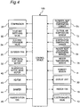
- FIG. 4 is a control block diagram of the air conditioner.
- the indoor unit 1 is provided with an indoor heat exchanger temperature sensor T4 that detects temperature of the indoor heat exchanger 11, an indoor temperature sensor T5 that detects temperature of a room where the indoor unit 1 is installed, and a humidity sensor H that detects humidity of the room where the indoor unit 1 is installed.
- the outdoor unit 2 is provided with an outdoor heat exchanger temperature sensor T1 that detects temperature of the outdoor heat exchanger 23, an outside air temperature sensor T2 that detects outside air temperature, and an evaporation temperature sensor T3 that detects evaporation temperature of the electric expansion valve 24.
- the air conditioner has the control device 100 that controls the indoor unit 1 and outdoor unit 2, and a remote controller (not shown).
- the control device 100 includes an indoor control unit (not shown) for the indoor unit 1 and an outdoor control unit (not shown)for the outdoor unit 2, each of which is provided with a central processing unit (CPU) that performs calculations, operations, or the like, a read only memory (ROM) that stores a program, data, or the like required for control of the indoor unit 1 and the outdoor unit 2, a random access memory (RAM), or the like.
- CPU central processing unit
- ROM read only memory
- RAM random access memory
- the control device 100 controls the compressor 21, the four-way switching valve 22, the electric expansion valve 24, the outdoor fan 20, the indoor fan 12, the electromagnetic valve 13, a display unit 30, a horizontal flap drive motor 32, the humidifying rotor drive motor 42, the heater 43, the damper 44, and the humidification fan 45 based on a signal or signals, or the like, from the remote controller or from one of the sensors (the outdoor heat exchanger temperature sensor T1, the outside air temperature sensor T2, the evaporation temperature sensor T3, the indoor heat exchanger temperature sensor T4, the indoor temperature sensor T5, and the humidity sensor H) of each of the indoor unit 1 and outdoor unit 2.
- the sensors the outdoor heat exchanger temperature sensor T1, the outside air temperature sensor T2, the evaporation temperature sensor T3, the indoor heat exchanger temperature sensor T4, the indoor temperature sensor T5, and the humidity sensor H
- the remote controller can change content of control of the indoor unit 1 and outdoor unit 2 by the control device 100.
- operation of the remote controller allows for selection of an operating mode of heating operation, cooling operation, or dehumidifying operation, performance of operation start, operation switching, or operation stop, setting or changing of indoor temperature or airflow volume, or starting or stopping of cleaning operation.
- FIG. 5 is a timing chart for describing a cleaning operation.
- an end of heating operation is used as information related to start of the cleaning operation, for example.
- the control device 100 receives information related to start of cleaning operation when the remote controller is operated to have the cleaning operation started, or when air conditioning operation ends, after the user having operated the remote controller to set the air conditioner to execute cleaning operation after an end of the air conditioning operation such as heating operation or cooling operation.
- the compressor 21 is stopped from operating, to prevent refrigerant from flowing to the refrigerant circuit RC, by which a flow rate of refrigerant to the indoor heat exchanger 11 is restricted.
- control device 100 controls the humidifying rotor drive motor 42, the heater 43, and the humidification fan 45 to rotate the humidifying rotor 41 of the humidification device 3 and turn on the heater 43 and the humidification fan 45 in order to prepare for supply of humidified air to the indoor unit 1 via the humidification hose 4.
- the indoor fan 12 is driven at a predetermined number of rotations.
- the predetermined number of rotations of the indoor fan 12 is a number of rotations capable of masking sound of the humidification fan transmitted from the humidification device 3.
- the horizontal flap 31 is opened to a predetermined opening degree so that a direction of blown-out air from the horizontal flap 31 is upward from the horizontal.
- the control device 100 controls the refrigerant circuit RC to restrict a flow rate of refrigerant to the indoor heat exchanger 11 during the preparation period (first time period) from when information related to start of the cleaning operation is received until the predetermined time T (20 minutes in this embodiment) elapses.
- the control device 100 controls the humidifying rotor drive motor 42, the heater 43, and the humidification fan 45 to rotate the humidifying rotor 41 of the humidification device 3 and turn on the heater 43 and the humidification fan 45 in order to prepare for supply of humidified air to the indoor unit 1 via the humidification hose 4.
- adsorption operation may be performed during the preparation period, in which the humidifying rotor 41 of the humidification device 3 is rotated to cause the adsorption area of the humidifying rotor 41 to adsorb moisture, and the humidified air may actually be introduced to the indoor unit 1 from the humidification device 3 after the cleaning operation starts.
- the indoor heat exchanger 11 is prevented from functioning as an evaporator until humidified air is substantially supplied from the humidification device 3 (humidified air supply device), by which excessive cooling of the casing 10 is prevented. Therefore, formation of dew condensation on the casing 10 can be reduced or suppressed when cleaning the indoor heat exchanger 11.
- blown-out air can be prevented from hitting a user in the room, because the control device 100 controls tilting of the horizontal flap 31 in the vertical direction to maintain the horizontal flap 31 tilted upward from the horizontal during the preparation period so that blown-out air is directed to a ceiling of the room.
- control device 100 controlling the indoor fan 12 to drive the indoor fan 12 at a predetermined number of rotations during the preparation period, it is possible to mask sound of a humidification fan, which is transmitted to the inside of the room via the humidification hose 4 and the indoor unit 1 from the humidification device 3 that has started operation in advance, or the like.
- water vapor included in humidified air from the humidification device 3 can form water droplets and form dew condensation in the indoor heat exchanger 11 while preventing the indoor heat exchanger 11 from freezing, by the control device 100 controlling the amount of refrigerant that flows to the indoor heat exchanger 11 and the number of rotations of the indoor fan 12 so that temperature of the indoor heat exchanger 11 that functions as an evaporator is higher than 0°C and equal to or lower than a dew-point temperature.
- An air conditioner according to a second embodiment of the present disclosure is identical in configuration to the air conditioner according to the first embodiment except for operation of a control device 100, and will therefore be described with reference to FIGS. 1 to 4 .
- the control device 100 executes cleaning operation without a preparation period. after executing humidifying operation in which a humidification device 3 (humidified air supply device) supplies humidified air to an indoor unit 1, or after executing humidifying heating operation in which the humidification device 3 supplies humidified air to the indoor unit 1, and an indoor heat exchanger 11 is caused to function as a condenser.
- a humidification device 3 humidity air supply device
- the humidification device 3 in the cleaning operation after an end of the humidifying operation in which the humidification device 3 supplies humidified air to the indoor unit 1, the humidification device 3 can immediately supply humidified air, and therefore, the cleaning operation can be started without a preparation period, and time can be saved as a result.
- the humidification device 3 can immediately supply humidified air, and therefore, the cleaning operation can be started without a preparation period, and time can be saved as a result.
- the air conditioner according to the second embodiment has effects similar to effects of the air conditioner of the first embodiment.
- An air conditioner according to a third embodiment of the present disclosure is identical in configuration to the air conditioner according to the first embodiment except for operation of a control device 100, and will therefore be described with also reference to FIGS. 1 to 4 .
- the compressor 21 is stopped from operating during a preparation period (first time period), to prevent refrigerant from flowing to the refrigerant circuit RC. Meanwhile, in the air conditioner according to the third embodiment, during the preparation period (first time period), the compressor 21 is operated, and an indoor heat exchanger 11 is caused to function as an evaporator in a cooling cycle.
- the capability of the indoor heat exchanger 11 as an evaporator can be reduced until humidified air is supplied from a humidification device 3 (humidified air supply device), by which excessive cooling of the casing 10 is prevented. Therefore, formation of dew condensation on the casing 10 can be reduced or suppressed when cleaning the indoor heat exchanger 11.
- the air conditioner according to the third embodiment has effects similar to effects of the air conditioner of the first embodiment.
- the humidified air supply device is not limited to the described one, and may be a humidified air supply device, which is included in an indoor unit and to which water for humidification is supplied from a water tank, or the like.
Landscapes
- Engineering & Computer Science (AREA)
- Chemical & Material Sciences (AREA)
- Combustion & Propulsion (AREA)
- Mechanical Engineering (AREA)
- General Engineering & Computer Science (AREA)
- Human Computer Interaction (AREA)
- Air Conditioning Control Device (AREA)
Abstract
Description
- The present disclosure relates to air conditioners.
- There is a conventional air conditioner that condenses moisture on a surface of an indoor heat exchanger to perform cleaning operation of the surface of the indoor heat exchanger with condensed water droplets (refer to Patent Literature 1:
Japanese Patent No. 6296633 - Patent Literature 1:
Japanese Patent No. 6296633 - There has been a problem with the air conditioner that a sufficient amount of water for cleaning the indoor heat exchanger cannot be obtained, because water droplets condensed in the indoor heat exchanger are formed from water vapor included in indoor air, and thus the quantity of water droplets that clean the surface of the indoor heat exchanger depends on the amount of moisture included in the indoor air.
- Therefore, in order to solve such a problem, there has been proposed an air conditioner capable of obtaining a sufficient amount of water for cleaning an indoor heat exchanger by including a humidified air supply device that supplies humidified air into an indoor unit.
- However, there has been a problem with the air conditioner including the humidified air supply device that excessive cooling of a casing causes dew condensation on the casing if the cleaning operation is started after heating operation or cooling operation ends and if the indoor heat exchanger is caused to function as an evaporator before humidified air is supplied from the humidified air supply device.
- The present disclosure proposes an air conditioner capable of reducing or suppressing formation of dew condensation on a casing when cleaning an indoor heat exchanger.
- An air conditioner according to an aspect of the present disclosure includes
a refrigerant circuit in which a compressor, an outdoor heat exchanger, an expansion mechanism, and an indoor heat exchanger are connected in a loop,
an indoor unit having a casing in which the indoor heat exchanger is disposed in an airflow pathway and an indoor fan disposed in the airflow pathway of the casing,
a humidified air supply device that supplies humidified air into the casing, and
a control device that performs cleaning operation of the indoor heat exchanger by controlling the refrigerant circuit and the humidified air supply device to supply humidified air from the humidified air supply device into the casing and to cause the indoor heat exchanger to function as an evaporator, in which
the control device controls, during a first time period from when information related to start of the cleaning operation is received until a predetermined time elapses, the refrigerant circuit to regulate a flow rate of refrigerant to the indoor heat exchanger more than during the cleaning operation or to set evaporation temperature of the indoor heat exchanger higher than during at a time of the cleaning operation, and
after the first time period, the control device controls the refrigerant circuit and the humidified air supply device to perform the cleaning operation. - According to the present disclosure, excessive cooling of a casing is prevented, because during the first time period from when information related to start of the cleaning operation (an end of heating operation, cooling operation, or the like) is received until the predetermined time elapses, the control device controls the refrigerant circuit to restrict a flow rate of refrigerant to the indoor heat exchanger more than during the cleaning operation or to set evaporation temperature of the indoor heat exchanger higher than during the cleaning operation, by which, during the first time period before starting the cleaning operation, the indoor heat exchanger is prevented from functioning as an evaporator or capability of the evaporator is reduced until after humidified air is supplied from the humidified air supply device. Therefore, formation of dew condensation on the casing can be reduced or suppressed when cleaning the indoor heat exchanger.
- An air conditioner according to one embodiment of the present disclosure includes a flap attached to a blow-out port of the casing in a vertically tiltable manner, in which the control device controls tilting of the flap in a vertical direction to maintain the flap tilted upward from a horizontal during the first time period.
- According to the present disclosure, blown-out air can be prevented from hitting a user in a room, because the control device controls tilting of the flap in the vertical direction to maintain the flap tilted upward from the horizontal during the first time period so that blown-out air is directed to a ceiling of the room.
- In the air conditioner according to one embodiment of the present disclosure, the control device controls the indoor fan to drive the indoor fan at a predetermined number of rotations during the first time period.
- According to the present disclosure, by the control device controlling the indoor fan to drive the indoor fan at a predetermined number of rotations during the first time period, it is possible to mask sound of a humidification fan or the like, which sound is transmitted from the humidified air supply device that has started operation in advance.
- In the air conditioner according to one embodiment of the present disclosure, the control device controls, during the cleaning operation, the amount of refrigerant that flows to the indoor heat exchanger and the number of rotations of the indoor fan so that temperature of the indoor heat exchanger that functions as an evaporator is higher than 0°C and equal to or lower than a dew-point temperature.
- According to the present disclosure, during the cleaning operation, water vapor included in humidified air from the humidified air supply device forms water droplets instead of freezing in the indoor heat exchanger by the control device controlling the amount of refrigerant that flows to the indoor heat exchanger and the number of rotations of the indoor fan so that the temperature of the indoor heat exchanger that functions as an evaporator is higher than 0°C and equal to or lower than a dew-point temperature.
- In the air conditioner according to one embodiment of the present disclosure, the cleaning operation is performed without the first time period after humidifying operation in which the humidified air supply device supplies humidified air to the indoor unit, or after humidifying heating operation in which the humidified air supply device supplies humidified air to the indoor unit and the indoor heat exchanger is caused to function as a condenser.
- According to the present disclosure, in cleaning operation after an end of humidifying operation in which the humidified air supply device supplies humidified air to the indoor unit, the humidified air supply device can immediately supply humidified air, and therefore, cleaning operation can be started without a first time period, and time can be saved as a result. Similarly, in cleaning operation after an end of the humidifying heating operation in which the humidified air supply device supplies humidified air to the indoor unit and the indoor heat exchanger is caused to function as a condenser, the humidified air supply device can immediately supply humidified air, and therefore, cleaning operation can be started without a first time period, and time can be saved as a result.
-
-
FIG. 1 is an external view of an air conditioner of a first embodiment of the present disclosure. -
FIG. 2 is a circuit diagram of the air conditioner. -
FIG. 3 is a schematic cross-sectional diagram of an indoor unit as viewed from line III-III inFIG. 1 . -
FIG. 4 is a control block diagram of the air conditioner. -
FIG. 5 is a timing chart for describing cleaning operation of the air conditioner. - Hereinafter, embodiments will be described. Note that, in the drawings, identical reference signs represent identical or corresponding parts. In addition, dimensions on the drawings such as a length, a width, a thickness, and a depth have appropriately been changed from actual scales on the drawings for clarification and simplification, and do not represent actual relative dimensions.
-
FIG. 1 is an external view of an air conditioner of a first embodiment of the present disclosure. - As shown in
FIG. 1 , the air conditioner according to the first embodiment is a pair-type air conditioner including anindoor unit 1 and anoutdoor unit 2 connected to theindoor unit 1 via refrigerant pipes L4 and L5. Furthermore, in the air conditioner, ahumidification device 3 connected to theindoor unit 1 via ahumidification hose 4 is provided on theoutdoor unit 2. Thehumidification device 3 is an example of a humidified air supply device. - Furthermore,
FIG. 2 is a circuit diagram of a refrigerant circuit RC included in the air conditioner. - The
indoor unit 1 of the air conditioner is, for example, a wall-mounted indoor unit attached to an indoor wall surface. Theindoor unit 1 has a casing 10 (shown inFIG. 3 ), anindoor heat exchanger 11, and anindoor fan 12 that sends air to theindoor heat exchanger 11. - The
indoor heat exchanger 11 is positioned on an upstream side of theindoor fan 12 with respect to air flow from theindoor fan 12. Theindoor heat exchanger 11 has a mainheat exchange unit 11a, an auxiliaryheat exchange unit 11b, and anelectromagnetic valve 13 in order to exchange heat between air from theindoor fan 12 and refrigerant. - Hereinafter, details of the main
heat exchange unit 11a and the auxiliaryheat exchange unit 11b will be described focusing on a refrigerant flow in a cooling cycle. - The main
heat exchange unit 11a includes afront section 11a-1 positioned on an indoor side and arear section 11a-2 positioned on a side opposite to the indoor side. Furthermore, thefront section 11a-1 is fluidly connected to therear section 11a-2 via refrigerant pipes L12 and L13 and theelectromagnetic valve 13. This allows refrigerant, which flows from anelectric expansion valve 24 on a side of theoutdoor unit 2 to the mainheat exchange unit 11a, to flow into therear section 11a-2 after flowing through thefront section 11a-1. - The auxiliary
heat exchange unit 11b is provided on a side opposite to therear section 11a-2 of the mainheat exchange unit 11a with respect to thefront section 11a-1 of the mainheat exchange unit 11a. That is, the auxiliaryheat exchange unit 11b is positioned on an indoor side of thefront section 11a-1 of the mainheat exchange unit 11a. The auxiliaryheat exchange unit 11b has a smaller capacity than a capacity of the mainheat exchange unit 11a. Furthermore, the refrigerant pipe L4 is connected to one end of the auxiliaryheat exchange unit 11b, and thefront section 11a-1 of the mainheat exchange unit 11a is connected to another end of the auxiliaryheat exchange unit 11b via a refrigerant pipe L11. This allows refrigerant from a side of theelectric expansion valve 24 on a side of theoutdoor unit 2 to be supplied to the mainheat exchange unit 11a via the auxiliaryheat exchange unit 11b. - As the
indoor fan 12, for example, a cross-flow fan is adopted. The cross-flow fan blows, to the inside of a room, air of which the temperature, or the like, is adjusted by theindoor heat exchanger 11. - The
electromagnetic valve 13 is provided on a middle portion of a refrigerant path of theindoor heat exchanger 11. More specifically, theelectromagnetic valve 13 is a valve for setting differential pressure between a side of thefront section 11a-1 of the mainheat exchange unit 11a and a side of therear section 11a-2 of the mainheat exchange unit 11a. Theelectromagnetic valve 13 is an on/off valve that can take only two positions, a large opening degree and a small opening degree, and is turned on when necessary (for example, during reheat dehumidifying operation described later) to be switched from the large opening degree position to the small opening degree position. - The
outdoor unit 2 of the air conditioner has acompressor 21, a four-way switching valve 22, anoutdoor heat exchanger 23, theelectric expansion valve 24 as an example of an expansion mechanism, anaccumulator 25, anoutdoor fan 20 that sends air to theoutdoor heat exchanger 23. - The
outdoor heat exchanger 23 is positioned downstream of theoutdoor fan 20 with respect to air flow from theoutdoor fan 20. The refrigerant that flows through theoutdoor heat exchanger 23 exchanges heat with air from theoutdoor fan 20. - The
expansion valve 24 is, for example, an electric valve that can be adjusted to three or more opening degrees different from one another, and the opening degree changes according to a signal from a control device 100 (shown inFIG. 4 ). - As shown in
FIG. 2 , thehumidification device 3 has a disk-shapedhumidifying rotor 41 provided with an adsorption area and a desorption area, a humidifyingrotor drive motor 42, aheater 43, adamper 44, ahumidification fan 45, and an outdoor unit-side humidification duct 46 to which thehumidification hose 4 is connected. - In the
humidifying rotor 41, an adsorbent such as silica gel, zeolite, or alumina is formed in a honeycomb shape or in a porous polygranular shape. The humidifyingrotor 41 is provided so as to be rotatable by the humidifyingrotor drive motor 42. - Furthermore, first and second air passages P1 and P2 for supplying humidified air are provided inside the
humidification device 3. - The first air passage P1 is disposed so that air sucked inside the
humidification device 3 by theoutdoor fan 20 passes through the adsorption area of thehumidifying rotor 41, and then discharged to outside. In the first air passage P1, moisture in the sucked air is adsorbed when the air passes through the adsorption area of thehumidifying rotor 41, and the air is discharged in a dry state to outside. - The second air passage P2 is disposed so that air sucked inside the
humidification device 3 by thehumidification fan 45 is heated by theheater 43, passes through the desorption area of thehumidifying rotor 41, and then supplied to theindoor unit 1 via the outdoor unit-side humidification duct 46. In the second air passage P2, the air sucked inside thehumidification device 3 is moisturized by moisture adsorbed in the adsorption area when passing through the desorption area of thehumidifying rotor 41, and then is supplied in a humidified state to theindoor unit 1. - The refrigerant circuit RC of the air conditioner includes the
indoor heat exchanger 11, thecompressor 21, the four-way switching valve 22, theoutdoor heat exchanger 23, theelectric expansion valve 24, theaccumulator 25, and refrigerant pipes L1 to L7. More specifically, theindoor heat exchanger 11, thecompressor 21, the four-way switching valve 22, theoutdoor heat exchanger 23, theelectric expansion valve 24, and theaccumulator 25 are fluidly connected by the refrigerant pipes L1 to L7. This configures a looped refrigerant circuit RC. In such a refrigerant circuit RC, refrigerant circulates when thecompressor 21 is driven. - Although not shown, the air conditioner includes a remote controller. The user can operate the remote controller to start or stop automatic air-conditioning operation, cooling operation, heating operation, dehumidifying operation, or the like.
-
FIG. 3 is a schematic cross-sectional diagram of theindoor unit 1 as viewed from line III-III inFIG. 1 . - As shown in
FIG. 3 , theindoor unit 1 includes theindoor heat exchanger 11 disposed in an airflow pathway Pw of thecasing 10. In addition, theindoor fan 12 is disposed in the airflow pathway Pw of thecasing 10 and on a downstream side of theindoor heat exchanger 11. Furthermore, ahorizontal flap 31 capable of tilting in the vertical direction is provided at a blow-outport 1a of the airflow pathway Pw of thecasing 10. Thehorizontal flap 31 is an example of a flap. The airflow pathway Pw of thecasing 10 is a pathway of air flow indicated by a thick solid arrow shown inFIG. 3 . - Furthermore, an indoor unit-
side humidification duct 51 to which the humidification hose 4 (shown inFIG. 2 ) is connected anddiffusion duct 52 are disposed in the airflow pathway Pw of thecasing 10 and on an upstream side of theindoor heat exchanger 11. Thediffusion duct 52 is connected to the indoor unit-side humidification duct 51 and extending in thecasing 10 in a horizontal direction (refer toFIG. 1 ). On a back wall of thediffusion duct 52, a plurality of humidification blow-out ports (not shown) is formed side by side in the horizontal direction. Humidified air flowed from the indoor unit-side humidification duct 51 into thediffusion duct 52 is blown out from the plurality of humidification blow-out ports toward theindoor heat exchanger 11. -
FIG. 4 is a control block diagram of the air conditioner. - As shown in
FIG. 4 , theindoor unit 1 is provided with an indoor heat exchanger temperature sensor T4 that detects temperature of theindoor heat exchanger 11, an indoor temperature sensor T5 that detects temperature of a room where theindoor unit 1 is installed, and a humidity sensor H that detects humidity of the room where theindoor unit 1 is installed. - As shown in
FIG. 4 , theoutdoor unit 2 is provided with an outdoor heat exchanger temperature sensor T1 that detects temperature of theoutdoor heat exchanger 23, an outside air temperature sensor T2 that detects outside air temperature, and an evaporation temperature sensor T3 that detects evaporation temperature of theelectric expansion valve 24. - Furthermore, as shown in
FIG. 4 , the air conditioner has thecontrol device 100 that controls theindoor unit 1 andoutdoor unit 2, and a remote controller (not shown). - The
control device 100 includes an indoor control unit (not shown) for theindoor unit 1 and an outdoor control unit (not shown)for theoutdoor unit 2, each of which is provided with a central processing unit (CPU) that performs calculations, operations, or the like, a read only memory (ROM) that stores a program, data, or the like required for control of theindoor unit 1 and theoutdoor unit 2, a random access memory (RAM), or the like. Thecontrol device 100 controls thecompressor 21, the four-way switching valve 22, theelectric expansion valve 24, theoutdoor fan 20, theindoor fan 12, theelectromagnetic valve 13, adisplay unit 30, a horizontalflap drive motor 32, the humidifyingrotor drive motor 42, theheater 43, thedamper 44, and thehumidification fan 45 based on a signal or signals, or the like, from the remote controller or from one of the sensors (the outdoor heat exchanger temperature sensor T1, the outside air temperature sensor T2, the evaporation temperature sensor T3, the indoor heat exchanger temperature sensor T4, the indoor temperature sensor T5, and the humidity sensor H) of each of theindoor unit 1 andoutdoor unit 2. - The remote controller can change content of control of the
indoor unit 1 andoutdoor unit 2 by thecontrol device 100. For example, operation of the remote controller allows for selection of an operating mode of heating operation, cooling operation, or dehumidifying operation, performance of operation start, operation switching, or operation stop, setting or changing of indoor temperature or airflow volume, or starting or stopping of cleaning operation. -
FIG. 5 is a timing chart for describing a cleaning operation. In this cleaning operation, an end of heating operation is used as information related to start of the cleaning operation, for example. Note that thecontrol device 100 receives information related to start of cleaning operation when the remote controller is operated to have the cleaning operation started, or when air conditioning operation ends, after the user having operated the remote controller to set the air conditioner to execute cleaning operation after an end of the air conditioning operation such as heating operation or cooling operation. - In
FIG. 5 , it is assumed that execution of cleaning operation after an end of an air conditioning operation such as heating operation or cooling operation has been set by operation of the remote controller. - First, after the heating operation stops, during a preparation period (first time period) until a predetermined time T (20 minutes in this embodiment) elapses, the
compressor 21 is stopped from operating, to prevent refrigerant from flowing to the refrigerant circuit RC, by which a flow rate of refrigerant to theindoor heat exchanger 11 is restricted. - In addition, operation of the
humidification device 3 starts at a time of start of the preparation period. Specifically, thecontrol device 100 controls the humidifyingrotor drive motor 42, theheater 43, and thehumidification fan 45 to rotate thehumidifying rotor 41 of thehumidification device 3 and turn on theheater 43 and thehumidification fan 45 in order to prepare for supply of humidified air to theindoor unit 1 via thehumidification hose 4. - Moreover, during the preparation period and during the cleaning operation, the
indoor fan 12 is driven at a predetermined number of rotations. The predetermined number of rotations of theindoor fan 12 is a number of rotations capable of masking sound of the humidification fan transmitted from thehumidification device 3. - Furthermore, during the preparation period and the cleaning operation, the
horizontal flap 31 is opened to a predetermined opening degree so that a direction of blown-out air from thehorizontal flap 31 is upward from the horizontal. - Then, when the preparation period ends and the cleaning operation starts, operation of the
compressor 21 is started, and theindoor heat exchanger 11 is caused to function as an evaporator in the cooling cycle. When temperature of theindoor heat exchanger 11 is higher than 0°C and equal to or lower than a dew-point temperature, water droplets start to adhere to theindoor heat exchanger 11. - In the air conditioner having the above configuration, the
control device 100 controls the refrigerant circuit RC to restrict a flow rate of refrigerant to theindoor heat exchanger 11 during the preparation period (first time period) from when information related to start of the cleaning operation is received until the predetermined time T (20 minutes in this embodiment) elapses. In this preparation period, thecontrol device 100 controls the humidifyingrotor drive motor 42, theheater 43, and thehumidification fan 45 to rotate thehumidifying rotor 41 of thehumidification device 3 and turn on theheater 43 and thehumidification fan 45 in order to prepare for supply of humidified air to theindoor unit 1 via thehumidification hose 4. - Note that, only adsorption operation may be performed during the preparation period, in which the
humidifying rotor 41 of thehumidification device 3 is rotated to cause the adsorption area of thehumidifying rotor 41 to adsorb moisture, and the humidified air may actually be introduced to theindoor unit 1 from thehumidification device 3 after the cleaning operation starts. - Thus, when cleaning operation is started after heating operation or cooling operation ends, the
indoor heat exchanger 11 is prevented from functioning as an evaporator until humidified air is substantially supplied from the humidification device 3 (humidified air supply device), by which excessive cooling of thecasing 10 is prevented. Therefore, formation of dew condensation on thecasing 10 can be reduced or suppressed when cleaning theindoor heat exchanger 11. - In addition, blown-out air can be prevented from hitting a user in the room, because the
control device 100 controls tilting of thehorizontal flap 31 in the vertical direction to maintain thehorizontal flap 31 tilted upward from the horizontal during the preparation period so that blown-out air is directed to a ceiling of the room. - Moreover, by the
control device 100 controlling theindoor fan 12 to drive theindoor fan 12 at a predetermined number of rotations during the preparation period, it is possible to mask sound of a humidification fan, which is transmitted to the inside of the room via thehumidification hose 4 and theindoor unit 1 from thehumidification device 3 that has started operation in advance, or the like. - Furthermore, during the cleaning operation, water vapor included in humidified air from the
humidification device 3 can form water droplets and form dew condensation in theindoor heat exchanger 11 while preventing theindoor heat exchanger 11 from freezing, by thecontrol device 100 controlling the amount of refrigerant that flows to theindoor heat exchanger 11 and the number of rotations of theindoor fan 12 so that temperature of theindoor heat exchanger 11 that functions as an evaporator is higher than 0°C and equal to or lower than a dew-point temperature. - An air conditioner according to a second embodiment of the present disclosure is identical in configuration to the air conditioner according to the first embodiment except for operation of a
control device 100, and will therefore be described with reference toFIGS. 1 to 4 . - In the air conditioner according to the second embodiment, the
control device 100 executes cleaning operation without a preparation period. after executing humidifying operation in which a humidification device 3 (humidified air supply device) supplies humidified air to anindoor unit 1, or after executing humidifying heating operation in which thehumidification device 3 supplies humidified air to theindoor unit 1, and anindoor heat exchanger 11 is caused to function as a condenser. - According to the air conditioner having the above configuration, in the cleaning operation after an end of the humidifying operation in which the
humidification device 3 supplies humidified air to theindoor unit 1, thehumidification device 3 can immediately supply humidified air, and therefore, the cleaning operation can be started without a preparation period, and time can be saved as a result. - Similarly, in the cleaning operation after an end of the humidifying heating operation in which the
humidification device 3 supplies humidified air to theindoor unit 1 and theindoor heat exchanger 11 is caused to function as a condenser, thehumidification device 3 can immediately supply humidified air, and therefore, the cleaning operation can be started without a preparation period, and time can be saved as a result. - The air conditioner according to the second embodiment has effects similar to effects of the air conditioner of the first embodiment.
- An air conditioner according to a third embodiment of the present disclosure is identical in configuration to the air conditioner according to the first embodiment except for operation of a
control device 100, and will therefore be described with also reference toFIGS. 1 to 4 . - In the air conditioner according to the first embodiment, after air conditioning operation such as heating operation or cooling operation stops, , the
compressor 21 is stopped from operating during a preparation period (first time period), to prevent refrigerant from flowing to the refrigerant circuit RC. Meanwhile, in the air conditioner according to the third embodiment, during the preparation period (first time period), thecompressor 21 is operated, and anindoor heat exchanger 11 is caused to function as an evaporator in a cooling cycle. At this time, a smaller amount of refrigerant, as compared to the subsequent cleaning operation, is flowed to theindoor heat exchanger 11 to restrict a flow rate of the refrigerant to theindoor heat exchanger 11, by which evaporation temperature Te of theindoor heat exchanger 11 detected by the indoor heat exchanger temperature sensor T4 is made higher than at a time of cleaning operation. - In the preparation period (first time period) before starting the cleaning operation, the capability of the
indoor heat exchanger 11 as an evaporator can be reduced until humidified air is supplied from a humidification device 3 (humidified air supply device), by which excessive cooling of thecasing 10 is prevented. Therefore, formation of dew condensation on thecasing 10 can be reduced or suppressed when cleaning theindoor heat exchanger 11. - The air conditioner according to the third embodiment has effects similar to effects of the air conditioner of the first embodiment.
- In the first to third embodiments described above, air conditioners including the
humidification device 3, which is a humidified air supply device, have been described. However, the humidified air supply device is not limited to the described one, and may be a humidified air supply device, which is included in an indoor unit and to which water for humidification is supplied from a water tank, or the like. - Specific embodiments of the present disclosure have been described. However, the present disclosure is not limited to the above first to third embodiments, and various modifications can be made within the scope of the present disclosure.
-
- 1
- Indoor unit
- 2
- Outdoor unit
- 3
- Humidification device
- 4
- Humidification hose
- 10
- Casing
- 11
- Indoor heat exchanger
- 11a
- Main heat exchange unit
- 11a-1
- Front section
- 11a-2
- Rear section
- 11b
- Auxiliary heat exchange unit
- 12
- Indoor fan
- 13
- Electromagnetic valve
- 20
- Outdoor fan
- 21
- Compressor
- 22
- Four-way switching valve
- 23
- Outdoor heat exchanger
- 24
- Electric expansion valve (expansion mechanism)
- 25
- Accumulator
- 31
- Horizontal flap
- 32
- Horizontal flap drive motor
- 41
- Humidifying rotor
- 42
- Humidifying rotor drive motor
- 43
- Heater
- 44
- Damper
- 45
- Humidification fan
- 46
- Outdoor unit-side humidification duct
- RC
- Refrigerant circuit
Claims (5)
- An air conditioner comprising:a refrigerant circuit (RC) in which a compressor (21), an outdoor heat exchanger (23), an expansion mechanism (24), and an indoor heat exchanger (11) are connected in a loop;an indoor unit (1) having a casing (10) in which the indoor heat exchanger (11) is disposed in an airflow pathway (Pw) and an indoor fan (12) disposed in the airflow pathway (Pw) of the casing (10);a humidified air supply device (3) that supplies humidified air into the casing (10); anda control device (100) that performs cleaning operation of the indoor heat exchanger (11) by controlling the refrigerant circuit (RC) and the humidified air supply device (3) to supply humidified air from the humidified air supply device (3) into the casing (10) and to cause the indoor heat exchanger (11) to function as an evaporator,wherein the control device (100) controls, during a first time period from when information related to start of the cleaning operation is received until a predetermined time elapses, the refrigerant circuit (RC) to regulate a flow rate of refrigerant to the indoor heat exchanger (11) more than during the cleaning operation or to set evaporation temperature (Te) of the indoor heat exchanger (11) higher than during the cleaning operation, and after the first time period, the control device (100) controls the refrigerant circuit (RC) and the humidified air supply device (3) to perform the cleaning operation.
- The air conditioner according to claim 1, the air conditioner further comprising:a flap (31) attached to a blow-out port (1a) of the casing (10) in a vertically tiltable manner,wherein the control device (100) controls tilting of the flap (31) in a vertical direction to maintain the flap (31) tilted upward from a horizontal during the first time period.
- The air conditioner according to claim 2, wherein the control device (100) controls the indoor fan (12) to drive the indoor fan (12) at a predetermined number of rotations during the first time period.
- The air conditioner according to any one of claim 1 to 3, wherein the control device (100) controls, during the cleaning operation, the amount of refrigerant that flows to the indoor heat exchanger (11) and the number of rotations of the indoor fan (12) so that temperature of the indoor heat exchanger (11) that functions as the evaporator is higher than 0°C and equal to or lower than a dew-point temperature.
- The air conditioner according to any one of claim 1 to 4, wherein the cleaning operation is performed without the first time period after humidifying operation in which the humidified air supply device (3) supplies humidified air to the indoor unit (1), or after humidifying heating operation in which the humidified air supply device (3) supplies humidified air to the indoor unit (1) and the indoor heat exchanger (11) is caused to function as a condenser.
Applications Claiming Priority (2)
| Application Number | Priority Date | Filing Date | Title |
|---|---|---|---|
| JP2018213540A JP6743869B2 (en) | 2018-11-14 | 2018-11-14 | Air conditioner |
| PCT/JP2019/035601 WO2020100395A1 (en) | 2018-11-14 | 2019-09-11 | Air conditioner |
Publications (2)
| Publication Number | Publication Date |
|---|---|
| EP3862642A1 true EP3862642A1 (en) | 2021-08-11 |
| EP3862642A4 EP3862642A4 (en) | 2021-12-01 |
Family
ID=70731119
Family Applications (1)
| Application Number | Title | Priority Date | Filing Date |
|---|---|---|---|
| EP19883559.7A Withdrawn EP3862642A4 (en) | 2018-11-14 | 2019-09-11 | AIR CONDITIONING |
Country Status (4)
| Country | Link |
|---|---|
| EP (1) | EP3862642A4 (en) |
| JP (1) | JP6743869B2 (en) |
| CN (1) | CN112823262B (en) |
| WO (1) | WO2020100395A1 (en) |
Families Citing this family (12)
| Publication number | Priority date | Publication date | Assignee | Title |
|---|---|---|---|---|
| DE102019121673A1 (en) | 2019-08-12 | 2021-02-18 | Schaeffler Technologies AG & Co. KG | Electrode unit and redox flow cell |
| CN114076389B (en) * | 2020-08-11 | 2023-06-02 | 海信空调有限公司 | Air conditioner and self-cleaning method |
| JP6963199B1 (en) * | 2020-08-26 | 2021-11-05 | ダイキン工業株式会社 | Indoor air conditioning system |
| JP7082299B2 (en) * | 2020-09-10 | 2022-06-08 | ダイキン工業株式会社 | Air conditioner |
| JP7628438B2 (en) * | 2021-02-22 | 2025-02-10 | 株式会社コロナ | Air conditioners |
| CN113357789B (en) * | 2021-05-20 | 2022-10-28 | 青岛海尔空调器有限总公司 | Control method and device for self-cleaning of air conditioner and air conditioner |
| CN117501053B (en) * | 2021-06-23 | 2024-11-19 | 大金工业株式会社 | Air conditioning device |
| JP7148690B1 (en) * | 2021-08-31 | 2022-10-05 | ダイキン工業株式会社 | air conditioner |
| CN114234351A (en) * | 2021-11-29 | 2022-03-25 | 青岛海尔空调器有限总公司 | Method and device for cleaning fan in air conditioner, air conditioner and readable storage medium |
| CN116164385A (en) * | 2022-10-31 | 2023-05-26 | 海信(广东)空调有限公司 | An air conditioner and its control method |
| CN115950050B (en) * | 2022-12-06 | 2024-07-05 | 珠海格力电器股份有限公司 | Air conditioner control method and device, electronic equipment and storage medium |
| JP2025161091A (en) * | 2024-04-11 | 2025-10-24 | 三菱重工サーマルシステムズ株式会社 | Air conditioner and method for controlling air conditioner |
Family Cites Families (7)
| Publication number | Priority date | Publication date | Assignee | Title |
|---|---|---|---|---|
| JP2009300030A (en) * | 2008-06-16 | 2009-12-24 | Daikin Ind Ltd | Air conditioner |
| JP5077099B2 (en) * | 2008-06-27 | 2012-11-21 | ダイキン工業株式会社 | Air conditioner |
| CN102410582A (en) * | 2011-11-07 | 2012-04-11 | 太仓新凯裕电子科技有限公司 | Air conditioning system |
| CN105299949A (en) * | 2015-12-01 | 2016-02-03 | 李丹 | Method and device for regulating evaporating temperature of refrigerating system to clean heat exchanger through condensate water |
| JP6276450B1 (en) * | 2017-04-28 | 2018-02-07 | 日立ジョンソンコントロールズ空調株式会社 | Air conditioner |
| JP6296633B1 (en) * | 2017-04-28 | 2018-03-20 | 日立ジョンソンコントロールズ空調株式会社 | Air conditioner |
| CN107525216A (en) * | 2017-07-26 | 2017-12-29 | 青岛海尔空调器有限总公司 | Air conditioner and its control method with self-cleaning function |
-
2018
- 2018-11-14 JP JP2018213540A patent/JP6743869B2/en active Active
-
2019
- 2019-09-11 CN CN201980066692.0A patent/CN112823262B/en active Active
- 2019-09-11 WO PCT/JP2019/035601 patent/WO2020100395A1/en not_active Ceased
- 2019-09-11 EP EP19883559.7A patent/EP3862642A4/en not_active Withdrawn
Also Published As
| Publication number | Publication date |
|---|---|
| JP6743869B2 (en) | 2020-08-19 |
| EP3862642A4 (en) | 2021-12-01 |
| WO2020100395A1 (en) | 2020-05-22 |
| JP2020079684A (en) | 2020-05-28 |
| CN112823262A (en) | 2021-05-18 |
| CN112823262B (en) | 2021-08-31 |
Similar Documents
| Publication | Publication Date | Title |
|---|---|---|
| EP3862642A1 (en) | Air conditioner | |
| EP2224182B1 (en) | Humidity control device | |
| EP2767772B1 (en) | Humidity control device | |
| JP2000220877A (en) | Ventilation air conditioner | |
| JP5292768B2 (en) | Humidity control device | |
| JP2009109124A (en) | Humidity control device | |
| JP2024068764A (en) | Air Conditioning Equipment | |
| JP4450120B2 (en) | Air conditioner | |
| JP2017155953A (en) | Air conditioner | |
| JP7633569B2 (en) | Humidifier and air conditioner | |
| JP2023126731A (en) | Air-conditioning system | |
| JP5332467B2 (en) | Humidity control system | |
| JP4107333B2 (en) | Ceiling-mounted air conditioner | |
| JP5082775B2 (en) | Ventilation equipment | |
| JP2021181863A (en) | Air conditioning system | |
| JP7182026B1 (en) | humidifier | |
| JP7189472B2 (en) | air conditioning system | |
| JP2023005534A (en) | ventilator | |
| JP2009109115A (en) | Humidity control device | |
| JP2023005592A (en) | Ventilation device | |
| JP2649986B2 (en) | Clean room using a direct expansion type heat exchanger | |
| JP7617432B2 (en) | Ventilation system | |
| JP7148690B1 (en) | air conditioner | |
| JP5109592B2 (en) | Humidity control device | |
| JP2024068878A (en) | Air Conditioning Equipment |
Legal Events
| Date | Code | Title | Description |
|---|---|---|---|
| STAA | Information on the status of an ep patent application or granted ep patent |
Free format text: STATUS: THE INTERNATIONAL PUBLICATION HAS BEEN MADE |
|
| PUAI | Public reference made under article 153(3) epc to a published international application that has entered the european phase |
Free format text: ORIGINAL CODE: 0009012 |
|
| STAA | Information on the status of an ep patent application or granted ep patent |
Free format text: STATUS: REQUEST FOR EXAMINATION WAS MADE |
|
| 17P | Request for examination filed |
Effective date: 20210503 |
|
| AK | Designated contracting states |
Kind code of ref document: A1 Designated state(s): AL AT BE BG CH CY CZ DE DK EE ES FI FR GB GR HR HU IE IS IT LI LT LU LV MC MK MT NL NO PL PT RO RS SE SI SK SM TR |
|
| REG | Reference to a national code |
Ref country code: DE Ref legal event code: R079 Free format text: PREVIOUS MAIN CLASS: F24F0011410000 Ipc: F24F0011300000 |
|
| A4 | Supplementary search report drawn up and despatched |
Effective date: 20211103 |
|
| RIC1 | Information provided on ipc code assigned before grant |
Ipc: F24F 1/0087 20190101ALI20211027BHEP Ipc: F24F 11/70 20180101ALI20211027BHEP Ipc: F24F 11/61 20180101ALI20211027BHEP Ipc: F24F 11/30 20180101AFI20211027BHEP |
|
| DAV | Request for validation of the european patent (deleted) | ||
| DAX | Request for extension of the european patent (deleted) | ||
| GRAP | Despatch of communication of intention to grant a patent |
Free format text: ORIGINAL CODE: EPIDOSNIGR1 |
|
| STAA | Information on the status of an ep patent application or granted ep patent |
Free format text: STATUS: GRANT OF PATENT IS INTENDED |
|
| INTG | Intention to grant announced |
Effective date: 20220906 |
|
| STAA | Information on the status of an ep patent application or granted ep patent |
Free format text: STATUS: THE APPLICATION IS DEEMED TO BE WITHDRAWN |
|
| 18D | Application deemed to be withdrawn |
Effective date: 20230117 |