EP3862588A1 - Adjustable spring assembly - Google Patents
Adjustable spring assembly Download PDFInfo
- Publication number
- EP3862588A1 EP3862588A1 EP20275033.7A EP20275033A EP3862588A1 EP 3862588 A1 EP3862588 A1 EP 3862588A1 EP 20275033 A EP20275033 A EP 20275033A EP 3862588 A1 EP3862588 A1 EP 3862588A1
- Authority
- EP
- European Patent Office
- Prior art keywords
- spring
- end portion
- shim
- edge wound
- turns
- Prior art date
- Legal status (The legal status is an assumption and is not a legal conclusion. Google has not performed a legal analysis and makes no representation as to the accuracy of the status listed.)
- Granted
Links
Images


Classifications
-
- F—MECHANICAL ENGINEERING; LIGHTING; HEATING; WEAPONS; BLASTING
- F16—ENGINEERING ELEMENTS AND UNITS; GENERAL MEASURES FOR PRODUCING AND MAINTAINING EFFECTIVE FUNCTIONING OF MACHINES OR INSTALLATIONS; THERMAL INSULATION IN GENERAL
- F16D—COUPLINGS FOR TRANSMITTING ROTATION; CLUTCHES; BRAKES
- F16D43/00—Automatic clutches
- F16D43/02—Automatic clutches actuated entirely mechanically
- F16D43/20—Automatic clutches actuated entirely mechanically controlled by torque, e.g. overload-release clutches, slip-clutches with means by which torque varies the clutching pressure
- F16D43/21—Automatic clutches actuated entirely mechanically controlled by torque, e.g. overload-release clutches, slip-clutches with means by which torque varies the clutching pressure with friction members
- F16D43/213—Automatic clutches actuated entirely mechanically controlled by torque, e.g. overload-release clutches, slip-clutches with means by which torque varies the clutching pressure with friction members with axially applied torque-limiting friction surfaces
- F16D43/215—Automatic clutches actuated entirely mechanically controlled by torque, e.g. overload-release clutches, slip-clutches with means by which torque varies the clutching pressure with friction members with axially applied torque-limiting friction surfaces with flat friction surfaces, e.g. discs
- F16D43/216—Automatic clutches actuated entirely mechanically controlled by torque, e.g. overload-release clutches, slip-clutches with means by which torque varies the clutching pressure with friction members with axially applied torque-limiting friction surfaces with flat friction surfaces, e.g. discs with multiple lamellae
-
- F—MECHANICAL ENGINEERING; LIGHTING; HEATING; WEAPONS; BLASTING
- F16—ENGINEERING ELEMENTS AND UNITS; GENERAL MEASURES FOR PRODUCING AND MAINTAINING EFFECTIVE FUNCTIONING OF MACHINES OR INSTALLATIONS; THERMAL INSULATION IN GENERAL
- F16F—SPRINGS; SHOCK-ABSORBERS; MEANS FOR DAMPING VIBRATION
- F16F1/00—Springs
- F16F1/02—Springs made of steel or other material having low internal friction; Wound, torsion, leaf, cup, ring or the like springs, the material of the spring not being relevant
- F16F1/025—Springs made of steel or other material having low internal friction; Wound, torsion, leaf, cup, ring or the like springs, the material of the spring not being relevant characterised by having a particular shape
- F16F1/028—Springs made of steel or other material having low internal friction; Wound, torsion, leaf, cup, ring or the like springs, the material of the spring not being relevant characterised by having a particular shape cylindrical, with radial openings
-
- F—MECHANICAL ENGINEERING; LIGHTING; HEATING; WEAPONS; BLASTING
- F16—ENGINEERING ELEMENTS AND UNITS; GENERAL MEASURES FOR PRODUCING AND MAINTAINING EFFECTIVE FUNCTIONING OF MACHINES OR INSTALLATIONS; THERMAL INSULATION IN GENERAL
- F16F—SPRINGS; SHOCK-ABSORBERS; MEANS FOR DAMPING VIBRATION
- F16F1/00—Springs
- F16F1/02—Springs made of steel or other material having low internal friction; Wound, torsion, leaf, cup, ring or the like springs, the material of the spring not being relevant
- F16F1/04—Wound springs
- F16F1/048—Wound springs with undulations, e.g. wavy springs
-
- F—MECHANICAL ENGINEERING; LIGHTING; HEATING; WEAPONS; BLASTING
- F16—ENGINEERING ELEMENTS AND UNITS; GENERAL MEASURES FOR PRODUCING AND MAINTAINING EFFECTIVE FUNCTIONING OF MACHINES OR INSTALLATIONS; THERMAL INSULATION IN GENERAL
- F16F—SPRINGS; SHOCK-ABSORBERS; MEANS FOR DAMPING VIBRATION
- F16F1/00—Springs
- F16F1/02—Springs made of steel or other material having low internal friction; Wound, torsion, leaf, cup, ring or the like springs, the material of the spring not being relevant
- F16F1/04—Wound springs
- F16F1/06—Wound springs with turns lying in cylindrical surfaces
-
- F—MECHANICAL ENGINEERING; LIGHTING; HEATING; WEAPONS; BLASTING
- F16—ENGINEERING ELEMENTS AND UNITS; GENERAL MEASURES FOR PRODUCING AND MAINTAINING EFFECTIVE FUNCTIONING OF MACHINES OR INSTALLATIONS; THERMAL INSULATION IN GENERAL
- F16F—SPRINGS; SHOCK-ABSORBERS; MEANS FOR DAMPING VIBRATION
- F16F1/00—Springs
- F16F1/02—Springs made of steel or other material having low internal friction; Wound, torsion, leaf, cup, ring or the like springs, the material of the spring not being relevant
- F16F1/04—Wound springs
- F16F1/12—Attachments or mountings
- F16F1/121—Attachments or mountings adjustable, e.g. to modify spring characteristics
-
- F—MECHANICAL ENGINEERING; LIGHTING; HEATING; WEAPONS; BLASTING
- F16—ENGINEERING ELEMENTS AND UNITS; GENERAL MEASURES FOR PRODUCING AND MAINTAINING EFFECTIVE FUNCTIONING OF MACHINES OR INSTALLATIONS; THERMAL INSULATION IN GENERAL
- F16F—SPRINGS; SHOCK-ABSORBERS; MEANS FOR DAMPING VIBRATION
- F16F1/00—Springs
- F16F1/02—Springs made of steel or other material having low internal friction; Wound, torsion, leaf, cup, ring or the like springs, the material of the spring not being relevant
- F16F1/32—Belleville-type springs
- F16F1/328—Belleville-type springs with undulations, e.g. wavy springs
-
- F—MECHANICAL ENGINEERING; LIGHTING; HEATING; WEAPONS; BLASTING
- F16—ENGINEERING ELEMENTS AND UNITS; GENERAL MEASURES FOR PRODUCING AND MAINTAINING EFFECTIVE FUNCTIONING OF MACHINES OR INSTALLATIONS; THERMAL INSULATION IN GENERAL
- F16F—SPRINGS; SHOCK-ABSORBERS; MEANS FOR DAMPING VIBRATION
- F16F1/00—Springs
- F16F1/02—Springs made of steel or other material having low internal friction; Wound, torsion, leaf, cup, ring or the like springs, the material of the spring not being relevant
- F16F1/04—Wound springs
- F16F1/12—Attachments or mountings
- F16F1/125—Attachments or mountings where the end coils of the spring engage an axial insert
Definitions
- the first end portion of the edge wound wave spring has an inner diameter and the shim body has an outer diameter which is smaller than the inner diameter of the first portion of the edge wound wave spring. This means that the shim body may be received radially within the first end portion of the edge wound wave spring, optionally with a sliding fit.
- the number of flat locating portions per turn of the first end portion of the edge wound wave spring may be equal to greater than the number of mounting lugs of the shim in some embodiments.
- the disclosure also provides an edge wound wave spring comprising a plurality of axially spaced, axially compressible wave-like turns extending between a first end portion and a second end portion, the first end portion comprising a plurality of closely arranged turns.
- the first end portion of the edge wound wave spring may comprise at least two, for example at least three, for example at least four, for example at least five turns.
- the first end portion 58 of the spring 52 comprises a plurality of closely arranged turns 64 of material.
- the turns 64 may be considered as being generally parallel. In the disclosed embodiment, there are five turns 64 in the first end portion 58. However, the particular number of turns 64 may vary depending on the amount of adjustment in the load to be applied by the spring 52. There need to be at least two turns 64 however to allow for mounting of the shim 54.
- the turns 64 may, in the rest state of the spring 52, touch each other as shown. In other embodiments, there may be a small spacing between the turns 64.
- a generally planar turn 76 may be provided at the base of the first end portion 58, separating it from the main axially compressible turns 56 of the spring 52.
- the shim body 66 is annular so as, for example, to allow for the passage through the shim body of a drive shaft such as shown in Figure 1 .
- this is not essential and the shim body 66 could, in other applications, be a solid disc.
Landscapes
- Engineering & Computer Science (AREA)
- General Engineering & Computer Science (AREA)
- Mechanical Engineering (AREA)
- Springs (AREA)
Abstract

Description
- The present disclosure relates to an adjustable spring assembly and a spring for use in such an assembly.
- Adjustable spring assemblies are used in a wide range of applications. One typical application is as a preloading spring in a torque limiting device. In a known construction of torque limiting device, drive is transmitted from an input shaft to an output shaft through a plurality of drive balls. The drive balls are received in pockets defined between elements rotationally coupled to the input and output shafts respectively. The elements are resiliently biased towards one another by means of a preloading spring, typically a compression coil spring. The pockets are ramped such that if the torque applied to the input shaft exceeds a predetermined value, set by the loading of the preloading spring, the drive balls may move up the ramped surface of the respective element and move the opposed element axially against the force of the preloading spring. This axial movement may be used to apply a braking force to the system, for example through friction plates, thereby limiting the torque transmissible through the system.
- In order to operate consistently, the preloading force applied by the spring must be accurately set. This is normally achieved by the use of a shim arranged between the spring and an opposed surface. Typically a unit is initially assembled with a shim and the unit tested. If the preload is not correct, then the unit must be disassembled and the shim machined, for example ground, to change its thickness. The unit is then reassembled and re-tested, and the process repeated until the appropriate preload is achieved. This may be time consuming.
- From a first aspect, the present disclosure comprises a spring assembly comprising an edge wound spring and a shim. The edge wound wave spring comprises a plurality of axially spaced, axially compressible wave-like turns extending between a first end portion and a second end portion. The first end portion comprises a plurality of closely arranged turns. The shim comprises a shim body and at least one mounting lug projecting radially from the shim body. The at least one mounting lug is received between adjacent turns of the first end portion of the edge wound wave spring for retaining the shim to the edge wound wave spring.
- In an embodiment of the above, the shim may comprise a plurality of mounting lugs. The mounting lugs may optionally be circumferentially equispaced about the shim body.
- In embodiments of any of the above, the first end portion of the edge wound wave spring has an inner diameter and the shim body has an outer diameter which is smaller than the inner diameter of the first portion of the edge wound wave spring. This means that the shim body may be received radially within the first end portion of the edge wound wave spring, optionally with a sliding fit.
- In embodiments of any of the above the shim body may be annular.
- In embodiments of any of the above the turns of the first end portion of the edge wound wave spring may comprise a plurality of generally flat locating portions joined by respective axially arched portions.
- The mounting lugs of the shim may be located axially between the flat locating portions of adjacent turns of the first end portion of the edge wound wave spring.
- The number of flat locating portions per turn of the first end portion of the edge wound wave spring may be equal to greater than the number of mounting lugs of the shim in some embodiments.
- In embodiments of any of the above the second end portion of the edge wound wave spring may comprises a planar turn.
- The disclosure also provides an edge wound wave spring comprising a plurality of axially spaced, axially compressible wave-like turns extending between a first end portion and a second end portion, the first end portion comprising a plurality of closely arranged turns.
- The turns of the first end portion of the edge wound wave spring may comprise a plurality of generally flat locating portions joined by respective axially arched portions.
- The second end portion of the edge wound wave spring may comprise a planar turn.
- In embodiments of any of the above, the first end portion of the edge wound wave spring may comprise at least two, for example at least three, for example at least four, for example at least five turns.
- The disclosure also provides a preloaded assembly comprising a spring assembly in accordance with the disclosure arranged axially between an axially movable element to be preloaded and a reaction element.
- The disclosure also provides a torque limiter comprising such a preloaded assembly, the axially movable element being a rotary element which is movable axially against the force of the spring assembly in the event of a torque in the torque limiter exceeding a predetermined value which is determined by the preload force of the spring assembly.
- The disclosure also provides a method of setting a preload in a spring assembly in accordance with the disclosure comprising screwing the at least one mounting lug of the shim into the turns of the first end portion of the edge wound wave spring, and rotating the shim until an overall axial length Lo of the spring assembly reaches a desired value representative of the desired preload.
- An embodiment of the disclosure will now be described, by way of example only, with reference to the accompanying drawings in which:
-
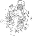
Figure 1 shows a torque limiting device; -
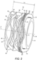
Figure 2 shows a spring assembly in accordance with the disclosure; -
Figure 3 shows an exploded view of the spring assembly ofFigure 2 ; -
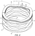
Figure 4 shows the spring of the spring assembly ofFigure 2 ; -
Figure 5 shows an end view of the spring of the spring assembly ofFigure 2 ; -
Figure 6 shows an end view of the shim of the spring assembly ofFigure 2 ; -
Figure 7 shows a sectional view along the line A-A ofFigure 6 . - Referring firstly to
Figure 1 , a torque limiter 2 comprises an input shaft 4 and anoutput shaft 6. The input shaft 4 comprisesinternal splines 8 for connection to a drive shaft not shown. The input shaft for further comprises external splines (not shown) which mesh with arotary element 12. Axially opposed to the rotary element 14 is an axiallymovable output element 16 which drives theoutput shaft 6 viadrive balls 18 arranged indrive pockets 20. A plurality ofdetent balls 22 are received inpockets 24 defined between the pocket-defining element 14 and theoutput element 16. - As can be seen from
Figure 1 , the axially facingsurface 26 of the pocket defining element 14 in thepocket 24 is ramped. It will also be seen that theoutput element 16 is resiliently biased towards the pocket defining element 14 by means of a preloadedcoil spring 28. Ashim 30 is arranged between oneend 32 of thecoil spring 28 and theoutput element 16. Theopposite end 34 of thecoil spring 28 is located against an axially fixedelement 36. - The
output element 16 is also coupled rotationally to a plurality ofrotary friction plates 38 which are arranged betweenstatic friction plates 40 mounted in thelimiter housing 42. - In normal operation, the preload of the
coil spring 28 is sufficient to maintain thedetent balls 22 in position at the bottom of the rampedsurface 26 of the pocket defining element 14 so that the output element is driven through thedetent balls 22. However, should input torque exceed a predetermined value, which is determined by the preload of thespring 28, thedetent balls 22 will be forced along the rampedsurface 26 so as to push theoutput element 16 axially forward. This in turn will move therotary friction plates 38 into contact with thestatic friction plates 40, thereby braking theoutput element 16 thereby limiting the torque transmitted through the device. - It will be appreciated that the torque at which the
detent balls 22 move up the rampedsurfaces 26 is determined by the preload in thespring 28. Accordingly, this must be set accurately so that the device operates reliably. This process is an iterative one, requiring potentially the use of a number of different size ofshims 30 to be tried before the appropriate preload is achieved. - In accordance with the disclosure, the shim and coil spring arrangement disclosed above may be substituted by a
spring assembly 50 as illustrated inFigures 2 to 4 . - With reference to
Figures 2 to 4 , aspring assembly 50 in accordance with the disclosure comprises an edgewound wave spring 52 and ashim 54 mounted to the edge woundwave spring 52. - Edge wound wave springs are springs which are wound from flattened spring wire. Such types of spring are generally known in the art and are manufactured by a number of different manufacturers, for example, Borrelly Spring Washers.
- As is known from existing spring designs, the edge wound
wave spring 52 of the disclosure comprises a plurality of axially compressible wave-like turns 56 extending between afirst end portion 58 and asecond end portion 60. Thecrests 62 ofadjacent turns 56 contact each other such that when thespring 52 is compressed axially, the wave-like turns 56 will deform and produce a reaction force. As shown, eachturn 56 is formed as a single turn although in other embodiments eachturn 56 may be formed as a plurality of closely adjacentparallel turns 56. - Unlike known designs, however, the
first end portion 58 of thespring 52 comprises a plurality of closely arranged turns 64 of material. The turns 64 may be considered as being generally parallel. In the disclosed embodiment, there are fiveturns 64 in thefirst end portion 58. However, the particular number ofturns 64 may vary depending on the amount of adjustment in the load to be applied by thespring 52. There need to be at least two turns 64 however to allow for mounting of theshim 54. The turns 64 may, in the rest state of thespring 52, touch each other as shown. In other embodiments, there may be a small spacing between theturns 64. A generallyplanar turn 76 may be provided at the base of thefirst end portion 58, separating it from the main axially compressible turns 56 of thespring 52. - As can be seen from
Figures 2 and3 , theshim 54 is mounted to thefirst end portion 58 of thespring 52. Theshim 54 comprises ashim body 66 and three mountinglug 68 which project radially outwardly from theshim body 66. The mounting lugs 68 are received betweenadjacent turns 64 of thefirst end portion 58 so as to retain theshim 54 on thespring 52. The outer diameter ODsh of theshim 54, defined by the outer edges of the mounting lugs 68 may, as shown, be slightly greater than, the outer diameter ODsp of thespring 52 such that the mounting lugs 68 protrude slightly from thespring 52. This may facilitate mounting of theshim 54. In other embodiments, however, the mounting lugs 68 may not protrude radially from thespring 52. - In this embodiment, there are three mounting
lugs 68. However, theshim body 66 may comprise a different number of mounting lugs 68. For example it may be possible to provide just a single mountinglug 68 in some embodiments or a different number of multiple mounting lugs 68, for example two or four mountinglugs 68. - In embodiments with multiple mounting lugs 68, the mounting lugs 68 may, as shown, be circumferentially equi-spaced about the external periphery of the
shim body 66. This helps distributes the clamping forces acting on theshim 54 evenly around theshim body 66. - The mounting lugs 68 may, as shown, be of a similar shape. For example as shown in
Figures 6 and 7 they may have the same axial thickness T, circumferential length L and radial height H. The axial thickness T of the mounting lugs 68 should be greater than any axial spacing between theturns 64 of thefirst end portion 58 of thespring 52 such that the mounting lugs 68 are clamped between theturns 64. The term "closely arranged turns" as used herein in relation to theturns 64 of thefirst end portion 58 may therefore be interpreted as having no axial spacing or a smaller axial spacing than the axial thickness T of the mounting lugs 68. - In the described embodiment, the
turns 64 of thefirst end portion 58 of thespring 54 are not planar, but undulate. Thus each turn 64 comprises a series of generallyflat locating portions 70 joined by a series of axiallyarched portions 72. As can be seen fromFigure 2 , the mounting lugs 68 of theshim body 66 are received between theflat locating portions 70 ofadjacent turns 64 of thefirst portion 58 of thespring 54. The circumferential length L of the mounting lugs 68 is slightly shorter than the circumferential lengthy L1 of the locatingportions 70. It will be understood that should theshim body 66 try to rotate 66 about its axis X in use (for example due to vibration) the mounting lugs 68 will after a very small rotation (for example less than 20°) come into contact with thearched portions 72 which will resist the rotation. Thearched portions 72 thus act as locking features. - In the disclosed embodiment, the number of locating
portions 70 is equal to the number of mounting lugs 68. However, this is not essential. In other embodiments for example, the number oflocation portions 70 may be greater than the number of mounting lugs 66, such that the circumferential spacing between the locatingportions 70 is less than the circumferential spacing between the mountinglugs 68. This may be advantageous in that it may allow for a finer adjustment of the position of theshim 54 on the spring 62 (due to the larger number of locating portions) while avoiding the need to provide a larger number of mounting lugs 68, which may be advantageous from a weight perspective. For example half the number of mountinglugs 68 may be provided at a circumferential spacing which is half that of the spacing of the locatingportions 70. - In this embodiment the
shim body 66 is annular so as, for example, to allow for the passage through the shim body of a drive shaft such as shown inFigure 1 . Of course, this is not essential and theshim body 66 could, in other applications, be a solid disc. - The
shim body 66 has an axially facingend surface 74 for engagement with an axially opposed surface in use. It also has a radiallyouter surface 78 having an outer diameter Do. The diameter Do is smaller than the inner diameter Di of the radiallyinner surface 80 defined by theturns 64 of the first end portion 58 (seeFigure 6 ). In some embodiments, theshim body 66 may be a sliding fit within thefirst end portion 58 of thespring 52 so as to assist in its radial location. - In embodiments of the disclosure, the mounting lugs 68 may be provided at an
end 82 of theshim body 66 opposite theend surface 70. This may help reduce the weight of the shim, avoiding the use of unnecessary additional shim material at that end of theshim 54. - In the embodiment illustrated the
second end portion 60 of thespring 52 comprises a single generallyplanar turn 84 having anaxially facing surface 86 for engaging an opposed surface in use. In other embodiments, thesecond end portion 60 of thespring 52 may comprise multiple turns to form a multi-layer integrated washer. - To assemble the
shim assembly 50, theshim 54 is in effect simply screwed into thefirst end portion 58 of thespring 52, that is, the mounting lugs 68 are screwed into theturns 64 of thefirst end portion 58. Theshim 54 is rotated as much as is necessary to produce a desired overall length Lo between the axially facingend surface 74 of theshim 54 and theaxially facing surface 84 of thesecond end portion 60. This overall length Lo will be greater than the spacing between two elements between the spring assembly is inserted, such that the spring assembly will be compressed when positioned, thereby preloading one of the elements for example preloading theoutput element 16 of the torque limiter 2 illustrated inFigure 1 . Theshim 54 is retained rotationally on thespring 52 due to the arrangement of the mounting lugs on the flat locating portions between thearched portions 72 of the first end portion turns 64. - If upon assembly of a device incorporating the
spring assembly 50, a preload is found not to be correct, the preload can be modified by simply rotating theshim 54 in an appropriate direction to move it further into or further out of thespring 52, thereby modifying the overall length Lo and thus the preload created by the spring assembly. This avoids the need for complete disassembly of a shim from a spring and its machining as was required in prior devices. - It will be appreciated that although the spring assembly of the disclosure has been described with reference to providing a preload in a torque limiter, the spring assembly may be used to provide a preload in any device requiring a preload, for example ball valves, detents, brake friction packs and so on.
Claims (15)
- A spring assembly (50) comprising:an edge wound wave spring (52) comprising a plurality of axially spaced, axially compressible wave-like turns (56) extending between a first end portion (58) and a second end portion (60), the first end portion (58) comprising a plurality of closely arranged turns (64); anda shim (54) comprising a shim body (66) and at least one mounting lug (68) projecting radially from the shim body (66), the at least one mounting lug (68) being received between adjacent turns (64) of the first end portion (58) of the edge wound wave spring (52) for retaining the shim (54) to the edge wound wave spring (52).
- A spring assembly as claimed in claim 1, wherein the shim (54) comprises a plurality of mounting lugs (68), the plurality of mounting lugs (68) optionally being circumferentially equispaced about the shim body (66).
- A spring assembly as claimed in claim 1 or 2, wherein the first end portion (60 of the edge wound wave spring (52) has an inner diameter Di and the shim body (66) has an outer diameter (Do) which is smaller than the inner diameter Di of the first portion (58) of the edge wound wave spring (52), whereby the shim body (66) may be received radially within the first end portion (58) of the edge wound wave spring (52), optionally with a sliding fit.
- A spring assembly as claimed in any preceding claim, wherein the shim body (66) is annular.
- A spring assembly as claimed in any preceding claim, wherein the turns (64) of the first end portion (58) of the edge wound wave spring (52) comprise a plurality of generally flat locating portions (70) joined by respective axially arched portions (72).
- A spring assembly as claimed in claim 5, wherein the mounting lugs (68) of the shim (54) are located axially between the flat locating portions (70) of adjacent turns (64) of the first end portion (58) of the edge wound wave spring (52).
- A spring assembly as claimed in claim 6, wherein the number of flat locating portions (70) per turn (64) of the first end portion (58) of the edge wound wave spring (52) is equal to greater than the number of mounting lugs (68) of the shim (54).
- A spring assembly as claimed in any preceding claim, wherein the second end portion (60) of the edge wound wave spring (52) comprises a planar turn (82).
- An edge wound wave spring (52) comprising a plurality of axially spaced, axially compressible wave-like turns (56) extending between a first end portion (58) and a second end portion (58) , the first end portion (58) comprising a plurality of closely arranged generally parallel turns (64).
- An edge wound wave spring as claimed in claim 9, wherein the turns (64) of the first end portion (58) of the edge wound wave spring (52) comprise a plurality of generally flat locating portions (70) joined by respective axially arched portions (72).
- An edge wound wave spring as claimed in claim 9 or 10, wherein the second end portion (60) of the edge wound wave spring (52) comprises a planar turn (82).
- A spring assembly or edge wound wave spring as claimed in any preceding claim, wherein the first end portion (58) of the edge wound wave spring (52) comprises at least two, for example at least three, for example at least four, for example at least five turns (64).
- A preloaded assembly comprising a spring assembly (50) as claimed in any preceding claim arranged axially between an axially movable element (16) to be preloaded and a fixed reaction element (36).
- A torque limiter (2) comprising a preloaded assembly as claimed in claim 13, the axially movable element (16) being a rotary element (16) which is movable axially against the force of the spring assembly (50) in the event of a torque in the torque limiter exceeding a predetermined value which is determined by the preload force of the spring assembly (50).
- A method of setting a preload in a spring assembly (50) as claimed in any of claims 1 to 8 or 12, comprising screwing the at least one mounting lug (68) of the shim (54) into the turns (64) of the first end portion (58) of the edge wound wave spring (52), and rotating the shim (54) until an overall axial length Lo of the spring assembly (50) reaches a desired value representative of the desired preload.
Priority Applications (2)
| Application Number | Priority Date | Filing Date | Title |
|---|---|---|---|
| EP20275033.7A EP3862588B1 (en) | 2020-02-10 | 2020-02-10 | Adjustable spring assembly |
| US17/169,823 US11585398B2 (en) | 2020-02-10 | 2021-02-08 | Adjustable spring assembly |
Applications Claiming Priority (1)
| Application Number | Priority Date | Filing Date | Title |
|---|---|---|---|
| EP20275033.7A EP3862588B1 (en) | 2020-02-10 | 2020-02-10 | Adjustable spring assembly |
Publications (2)
| Publication Number | Publication Date |
|---|---|
| EP3862588A1 true EP3862588A1 (en) | 2021-08-11 |
| EP3862588B1 EP3862588B1 (en) | 2023-04-19 |
Family
ID=69570605
Family Applications (1)
| Application Number | Title | Priority Date | Filing Date |
|---|---|---|---|
| EP20275033.7A Active EP3862588B1 (en) | 2020-02-10 | 2020-02-10 | Adjustable spring assembly |
Country Status (2)
| Country | Link |
|---|---|
| US (1) | US11585398B2 (en) |
| EP (1) | EP3862588B1 (en) |
Families Citing this family (2)
| Publication number | Priority date | Publication date | Assignee | Title |
|---|---|---|---|---|
| CN114151485A (en) * | 2020-09-07 | 2022-03-08 | 本田技研工业株式会社 | resin spring |
| US20250172184A1 (en) * | 2023-11-27 | 2025-05-29 | Smalley Steel Ring Company | Nested crest-to-crest wave spring |
Citations (5)
| Publication number | Priority date | Publication date | Assignee | Title |
|---|---|---|---|---|
| DE1780439U (en) * | 1958-10-29 | 1958-12-31 | J C Eckardt A G | DEVICE FOR FASTENING COIL SPRINGS. |
| JPH09177852A (en) * | 1995-12-25 | 1997-07-11 | Mitsubishi Steel Mfg Co Ltd | Coiled wave spring with nonlinear characteristics |
| JP2009192035A (en) * | 2008-02-18 | 2009-08-27 | Showa Hatsujo Seisakusho:Kk | Spring characteristic adjusting method for compression type coil spring and spring characteristic adjusting type compression biasing body |
| US20150111650A1 (en) * | 2013-10-21 | 2015-04-23 | Moog Inc. | Non-chattering ball detent torque limiter |
| JP2017227241A (en) * | 2016-06-21 | 2017-12-28 | 株式会社昌和発條製作所 | Compression type coil spring |
Family Cites Families (15)
| Publication number | Priority date | Publication date | Assignee | Title |
|---|---|---|---|---|
| US4579201A (en) | 1983-05-16 | 1986-04-01 | Curtiss Wright Flight Systems, Inc. | Bidirectional, torque-limiting, no-back clutch mechanism |
| US4898265A (en) | 1988-01-27 | 1990-02-06 | Sundstrand Corporation | Torque limiter |
| US4901987A (en) * | 1988-05-03 | 1990-02-20 | Smalley Steel Ring Company | Crest-to-crest compression spring with circular flat shim ends |
| US5558393A (en) * | 1995-01-24 | 1996-09-24 | Proteus Engineering, Inc. | Composite multi-wave compression spring |
| US5639074A (en) * | 1996-03-05 | 1997-06-17 | Smalley Steel Ring Co. | Interlaced wave spring |
| US6068250A (en) * | 1996-09-23 | 2000-05-30 | Proteus Engineering Inc. | Composite multi-wave compression spring |
| CA2419926C (en) * | 2000-08-17 | 2009-11-10 | E. Bayne Carew | Filter assembly, filter element, and method of utilizing the same |
| US6758465B1 (en) * | 2002-03-05 | 2004-07-06 | Smalley Steel Ring Company | Wave spring with single shim end |
| US6669184B2 (en) * | 2002-05-29 | 2003-12-30 | Visteon Global Technologies, Inc. | Composite wave ring spring |
| US7210181B1 (en) * | 2003-10-10 | 2007-05-01 | Atlanta Attachment Company | Spring construction |
| GB0427420D0 (en) * | 2004-12-15 | 2005-01-19 | Kohler Mira Ltd | Improvements in or relating to thermostatic mixing valves |
| JP4549998B2 (en) * | 2006-03-31 | 2010-09-22 | 株式会社パイオラックス | Corrugated coil spring |
| US20080111289A1 (en) * | 2006-11-10 | 2008-05-15 | Matsumura Kohki Co., Ltd. | Wave spring |
| CA2676064A1 (en) | 2007-02-01 | 2008-08-07 | Edward A. Mayer | Torque brake |
| EP2947342B1 (en) | 2014-05-19 | 2017-04-05 | Goodrich Actuation Systems Ltd. | Torque limiter |
-
2020
- 2020-02-10 EP EP20275033.7A patent/EP3862588B1/en active Active
-
2021
- 2021-02-08 US US17/169,823 patent/US11585398B2/en active Active
Patent Citations (5)
| Publication number | Priority date | Publication date | Assignee | Title |
|---|---|---|---|---|
| DE1780439U (en) * | 1958-10-29 | 1958-12-31 | J C Eckardt A G | DEVICE FOR FASTENING COIL SPRINGS. |
| JPH09177852A (en) * | 1995-12-25 | 1997-07-11 | Mitsubishi Steel Mfg Co Ltd | Coiled wave spring with nonlinear characteristics |
| JP2009192035A (en) * | 2008-02-18 | 2009-08-27 | Showa Hatsujo Seisakusho:Kk | Spring characteristic adjusting method for compression type coil spring and spring characteristic adjusting type compression biasing body |
| US20150111650A1 (en) * | 2013-10-21 | 2015-04-23 | Moog Inc. | Non-chattering ball detent torque limiter |
| JP2017227241A (en) * | 2016-06-21 | 2017-12-28 | 株式会社昌和発條製作所 | Compression type coil spring |
Also Published As
| Publication number | Publication date |
|---|---|
| US20210246958A1 (en) | 2021-08-12 |
| EP3862588B1 (en) | 2023-04-19 |
| US11585398B2 (en) | 2023-02-21 |
Similar Documents
| Publication | Publication Date | Title |
|---|---|---|
| US11585398B2 (en) | Adjustable spring assembly | |
| US6247377B1 (en) | Anti-lash gear assembly | |
| US20200141476A1 (en) | Limited slip differential with clutch for inhibiting speed differentiation between side gears | |
| CA2890718C (en) | Torque limiter | |
| KR100408803B1 (en) | Damper mechanism | |
| US20200248752A1 (en) | Torsion damping device with activatable friction device | |
| US20220186787A1 (en) | Strain wave gearbox with over-torque protection | |
| US7197807B2 (en) | Castellated snap ring retention system and method | |
| US12404904B2 (en) | Clutch, industrial robot and the use thereof | |
| JPH0461210B2 (en) | ||
| JPH0256529B2 (en) | ||
| EP3351754A1 (en) | Cam phasing system | |
| US10738837B2 (en) | Torque limiter assembly | |
| US5911788A (en) | Compliant gear | |
| US7562607B2 (en) | Torque-limiting tool | |
| EP3387281B1 (en) | Anti-backlash clutch plates | |
| US20200049239A1 (en) | Mechatronic system with shock absorber | |
| WO2011012192A1 (en) | Slip clutch | |
| US3267771A (en) | Motion transmitting mechanism | |
| US5707291A (en) | Stressed hoop slip clutch | |
| WO1992022754A1 (en) | Friction clutch driven plates | |
| US11473610B2 (en) | Ratcheting secondary locking feature | |
| EP3070350B1 (en) | Bearing assembly having an anti-rotation device | |
| JP2022045579A (en) | clutch | |
| JP2018091443A (en) | Closure device of housing end part and torque limiter with closure device |
Legal Events
| Date | Code | Title | Description |
|---|---|---|---|
| PUAI | Public reference made under article 153(3) epc to a published international application that has entered the european phase |
Free format text: ORIGINAL CODE: 0009012 |
|
| STAA | Information on the status of an ep patent application or granted ep patent |
Free format text: STATUS: THE APPLICATION HAS BEEN PUBLISHED |
|
| AK | Designated contracting states |
Kind code of ref document: A1 Designated state(s): AL AT BE BG CH CY CZ DE DK EE ES FI FR GB GR HR HU IE IS IT LI LT LU LV MC MK MT NL NO PL PT RO RS SE SI SK SM TR |
|
| STAA | Information on the status of an ep patent application or granted ep patent |
Free format text: STATUS: REQUEST FOR EXAMINATION WAS MADE |
|
| 17P | Request for examination filed |
Effective date: 20220211 |
|
| RBV | Designated contracting states (corrected) |
Designated state(s): AL AT BE BG CH CY CZ DE DK EE ES FI FR GB GR HR HU IE IS IT LI LT LU LV MC MK MT NL NO PL PT RO RS SE SI SK SM TR |
|
| GRAP | Despatch of communication of intention to grant a patent |
Free format text: ORIGINAL CODE: EPIDOSNIGR1 |
|
| STAA | Information on the status of an ep patent application or granted ep patent |
Free format text: STATUS: GRANT OF PATENT IS INTENDED |
|
| INTG | Intention to grant announced |
Effective date: 20221024 |
|
| GRAS | Grant fee paid |
Free format text: ORIGINAL CODE: EPIDOSNIGR3 |
|
| GRAA | (expected) grant |
Free format text: ORIGINAL CODE: 0009210 |
|
| STAA | Information on the status of an ep patent application or granted ep patent |
Free format text: STATUS: THE PATENT HAS BEEN GRANTED |
|
| RAP3 | Party data changed (applicant data changed or rights of an application transferred) |
Owner name: GOODRICH ACTUATION SYSTEMS LIMITED |
|
| AK | Designated contracting states |
Kind code of ref document: B1 Designated state(s): AL AT BE BG CH CY CZ DE DK EE ES FI FR GB GR HR HU IE IS IT LI LT LU LV MC MK MT NL NO PL PT RO RS SE SI SK SM TR |
|
| REG | Reference to a national code |
Ref country code: GB Ref legal event code: FG4D |
|
| REG | Reference to a national code |
Ref country code: DE Ref legal event code: R096 Ref document number: 602020009869 Country of ref document: DE |
|
| REG | Reference to a national code |
Ref country code: CH Ref legal event code: EP |
|
| REG | Reference to a national code |
Ref country code: IE Ref legal event code: FG4D |
|
| REG | Reference to a national code |
Ref country code: AT Ref legal event code: REF Ref document number: 1561397 Country of ref document: AT Kind code of ref document: T Effective date: 20230515 |
|
| REG | Reference to a national code |
Ref country code: LT Ref legal event code: MG9D |
|
| REG | Reference to a national code |
Ref country code: NL Ref legal event code: MP Effective date: 20230419 |
|
| REG | Reference to a national code |
Ref country code: AT Ref legal event code: MK05 Ref document number: 1561397 Country of ref document: AT Kind code of ref document: T Effective date: 20230419 |
|
| PG25 | Lapsed in a contracting state [announced via postgrant information from national office to epo] |
Ref country code: NL Free format text: LAPSE BECAUSE OF FAILURE TO SUBMIT A TRANSLATION OF THE DESCRIPTION OR TO PAY THE FEE WITHIN THE PRESCRIBED TIME-LIMIT Effective date: 20230419 |
|
| PG25 | Lapsed in a contracting state [announced via postgrant information from national office to epo] |
Ref country code: SE Free format text: LAPSE BECAUSE OF FAILURE TO SUBMIT A TRANSLATION OF THE DESCRIPTION OR TO PAY THE FEE WITHIN THE PRESCRIBED TIME-LIMIT Effective date: 20230419 Ref country code: PT Free format text: LAPSE BECAUSE OF FAILURE TO SUBMIT A TRANSLATION OF THE DESCRIPTION OR TO PAY THE FEE WITHIN THE PRESCRIBED TIME-LIMIT Effective date: 20230821 Ref country code: NO Free format text: LAPSE BECAUSE OF FAILURE TO SUBMIT A TRANSLATION OF THE DESCRIPTION OR TO PAY THE FEE WITHIN THE PRESCRIBED TIME-LIMIT Effective date: 20230719 Ref country code: ES Free format text: LAPSE BECAUSE OF FAILURE TO SUBMIT A TRANSLATION OF THE DESCRIPTION OR TO PAY THE FEE WITHIN THE PRESCRIBED TIME-LIMIT Effective date: 20230419 Ref country code: AT Free format text: LAPSE BECAUSE OF FAILURE TO SUBMIT A TRANSLATION OF THE DESCRIPTION OR TO PAY THE FEE WITHIN THE PRESCRIBED TIME-LIMIT Effective date: 20230419 |
|
| PG25 | Lapsed in a contracting state [announced via postgrant information from national office to epo] |
Ref country code: RS Free format text: LAPSE BECAUSE OF FAILURE TO SUBMIT A TRANSLATION OF THE DESCRIPTION OR TO PAY THE FEE WITHIN THE PRESCRIBED TIME-LIMIT Effective date: 20230419 Ref country code: PL Free format text: LAPSE BECAUSE OF FAILURE TO SUBMIT A TRANSLATION OF THE DESCRIPTION OR TO PAY THE FEE WITHIN THE PRESCRIBED TIME-LIMIT Effective date: 20230419 Ref country code: LV Free format text: LAPSE BECAUSE OF FAILURE TO SUBMIT A TRANSLATION OF THE DESCRIPTION OR TO PAY THE FEE WITHIN THE PRESCRIBED TIME-LIMIT Effective date: 20230419 Ref country code: LT Free format text: LAPSE BECAUSE OF FAILURE TO SUBMIT A TRANSLATION OF THE DESCRIPTION OR TO PAY THE FEE WITHIN THE PRESCRIBED TIME-LIMIT Effective date: 20230419 Ref country code: IS Free format text: LAPSE BECAUSE OF FAILURE TO SUBMIT A TRANSLATION OF THE DESCRIPTION OR TO PAY THE FEE WITHIN THE PRESCRIBED TIME-LIMIT Effective date: 20230819 Ref country code: HR Free format text: LAPSE BECAUSE OF FAILURE TO SUBMIT A TRANSLATION OF THE DESCRIPTION OR TO PAY THE FEE WITHIN THE PRESCRIBED TIME-LIMIT Effective date: 20230419 Ref country code: GR Free format text: LAPSE BECAUSE OF FAILURE TO SUBMIT A TRANSLATION OF THE DESCRIPTION OR TO PAY THE FEE WITHIN THE PRESCRIBED TIME-LIMIT Effective date: 20230720 Ref country code: AL Free format text: LAPSE BECAUSE OF FAILURE TO SUBMIT A TRANSLATION OF THE DESCRIPTION OR TO PAY THE FEE WITHIN THE PRESCRIBED TIME-LIMIT Effective date: 20230419 |
|
| PG25 | Lapsed in a contracting state [announced via postgrant information from national office to epo] |
Ref country code: FI Free format text: LAPSE BECAUSE OF FAILURE TO SUBMIT A TRANSLATION OF THE DESCRIPTION OR TO PAY THE FEE WITHIN THE PRESCRIBED TIME-LIMIT Effective date: 20230419 |
|
| PG25 | Lapsed in a contracting state [announced via postgrant information from national office to epo] |
Ref country code: SK Free format text: LAPSE BECAUSE OF FAILURE TO SUBMIT A TRANSLATION OF THE DESCRIPTION OR TO PAY THE FEE WITHIN THE PRESCRIBED TIME-LIMIT Effective date: 20230419 |
|
| REG | Reference to a national code |
Ref country code: DE Ref legal event code: R097 Ref document number: 602020009869 Country of ref document: DE |
|
| PG25 | Lapsed in a contracting state [announced via postgrant information from national office to epo] |
Ref country code: SM Free format text: LAPSE BECAUSE OF FAILURE TO SUBMIT A TRANSLATION OF THE DESCRIPTION OR TO PAY THE FEE WITHIN THE PRESCRIBED TIME-LIMIT Effective date: 20230419 Ref country code: SK Free format text: LAPSE BECAUSE OF FAILURE TO SUBMIT A TRANSLATION OF THE DESCRIPTION OR TO PAY THE FEE WITHIN THE PRESCRIBED TIME-LIMIT Effective date: 20230419 Ref country code: RO Free format text: LAPSE BECAUSE OF FAILURE TO SUBMIT A TRANSLATION OF THE DESCRIPTION OR TO PAY THE FEE WITHIN THE PRESCRIBED TIME-LIMIT Effective date: 20230419 Ref country code: EE Free format text: LAPSE BECAUSE OF FAILURE TO SUBMIT A TRANSLATION OF THE DESCRIPTION OR TO PAY THE FEE WITHIN THE PRESCRIBED TIME-LIMIT Effective date: 20230419 Ref country code: DK Free format text: LAPSE BECAUSE OF FAILURE TO SUBMIT A TRANSLATION OF THE DESCRIPTION OR TO PAY THE FEE WITHIN THE PRESCRIBED TIME-LIMIT Effective date: 20230419 Ref country code: CZ Free format text: LAPSE BECAUSE OF FAILURE TO SUBMIT A TRANSLATION OF THE DESCRIPTION OR TO PAY THE FEE WITHIN THE PRESCRIBED TIME-LIMIT Effective date: 20230419 |
|
| PLBE | No opposition filed within time limit |
Free format text: ORIGINAL CODE: 0009261 |
|
| STAA | Information on the status of an ep patent application or granted ep patent |
Free format text: STATUS: NO OPPOSITION FILED WITHIN TIME LIMIT |
|
| 26N | No opposition filed |
Effective date: 20240122 |
|
| PG25 | Lapsed in a contracting state [announced via postgrant information from national office to epo] |
Ref country code: SI Free format text: LAPSE BECAUSE OF FAILURE TO SUBMIT A TRANSLATION OF THE DESCRIPTION OR TO PAY THE FEE WITHIN THE PRESCRIBED TIME-LIMIT Effective date: 20230419 |
|
| PG25 | Lapsed in a contracting state [announced via postgrant information from national office to epo] |
Ref country code: SI Free format text: LAPSE BECAUSE OF FAILURE TO SUBMIT A TRANSLATION OF THE DESCRIPTION OR TO PAY THE FEE WITHIN THE PRESCRIBED TIME-LIMIT Effective date: 20230419 |
|
| PG25 | Lapsed in a contracting state [announced via postgrant information from national office to epo] |
Ref country code: MC Free format text: LAPSE BECAUSE OF FAILURE TO SUBMIT A TRANSLATION OF THE DESCRIPTION OR TO PAY THE FEE WITHIN THE PRESCRIBED TIME-LIMIT Effective date: 20230419 |
|
| REG | Reference to a national code |
Ref country code: CH Ref legal event code: PL |
|
| PG25 | Lapsed in a contracting state [announced via postgrant information from national office to epo] |
Ref country code: LU Free format text: LAPSE BECAUSE OF NON-PAYMENT OF DUE FEES Effective date: 20240210 |
|
| PG25 | Lapsed in a contracting state [announced via postgrant information from national office to epo] |
Ref country code: CH Free format text: LAPSE BECAUSE OF NON-PAYMENT OF DUE FEES Effective date: 20240229 |
|
| PG25 | Lapsed in a contracting state [announced via postgrant information from national office to epo] |
Ref country code: LU Free format text: LAPSE BECAUSE OF NON-PAYMENT OF DUE FEES Effective date: 20240210 Ref country code: CH Free format text: LAPSE BECAUSE OF NON-PAYMENT OF DUE FEES Effective date: 20240229 |
|
| PG25 | Lapsed in a contracting state [announced via postgrant information from national office to epo] |
Ref country code: BG Free format text: LAPSE BECAUSE OF FAILURE TO SUBMIT A TRANSLATION OF THE DESCRIPTION OR TO PAY THE FEE WITHIN THE PRESCRIBED TIME-LIMIT Effective date: 20230419 |
|
| PG25 | Lapsed in a contracting state [announced via postgrant information from national office to epo] |
Ref country code: BG Free format text: LAPSE BECAUSE OF FAILURE TO SUBMIT A TRANSLATION OF THE DESCRIPTION OR TO PAY THE FEE WITHIN THE PRESCRIBED TIME-LIMIT Effective date: 20230419 |
|
| REG | Reference to a national code |
Ref country code: BE Ref legal event code: MM Effective date: 20240229 |
|
| PG25 | Lapsed in a contracting state [announced via postgrant information from national office to epo] |
Ref country code: BE Free format text: LAPSE BECAUSE OF NON-PAYMENT OF DUE FEES Effective date: 20240229 |
|
| PG25 | Lapsed in a contracting state [announced via postgrant information from national office to epo] |
Ref country code: IE Free format text: LAPSE BECAUSE OF NON-PAYMENT OF DUE FEES Effective date: 20240210 |
|
| PG25 | Lapsed in a contracting state [announced via postgrant information from national office to epo] |
Ref country code: IE Free format text: LAPSE BECAUSE OF NON-PAYMENT OF DUE FEES Effective date: 20240210 Ref country code: BE Free format text: LAPSE BECAUSE OF NON-PAYMENT OF DUE FEES Effective date: 20240229 |
|
| PG25 | Lapsed in a contracting state [announced via postgrant information from national office to epo] |
Ref country code: CY Free format text: LAPSE BECAUSE OF FAILURE TO SUBMIT A TRANSLATION OF THE DESCRIPTION OR TO PAY THE FEE WITHIN THE PRESCRIBED TIME-LIMIT; INVALID AB INITIO Effective date: 20200210 |
|
| PG25 | Lapsed in a contracting state [announced via postgrant information from national office to epo] |
Ref country code: HU Free format text: LAPSE BECAUSE OF FAILURE TO SUBMIT A TRANSLATION OF THE DESCRIPTION OR TO PAY THE FEE WITHIN THE PRESCRIBED TIME-LIMIT; INVALID AB INITIO Effective date: 20200210 |
|
| PG25 | Lapsed in a contracting state [announced via postgrant information from national office to epo] |
Ref country code: TR Free format text: LAPSE BECAUSE OF FAILURE TO SUBMIT A TRANSLATION OF THE DESCRIPTION OR TO PAY THE FEE WITHIN THE PRESCRIBED TIME-LIMIT Effective date: 20230419 |
|
| PGFP | Annual fee paid to national office [announced via postgrant information from national office to epo] |
Ref country code: GB Payment date: 20260219 Year of fee payment: 7 |
|
| PGFP | Annual fee paid to national office [announced via postgrant information from national office to epo] |
Ref country code: DE Payment date: 20260206 Year of fee payment: 7 |
|
| PGFP | Annual fee paid to national office [announced via postgrant information from national office to epo] |
Ref country code: IT Payment date: 20260209 Year of fee payment: 7 |
|
| PGFP | Annual fee paid to national office [announced via postgrant information from national office to epo] |
Ref country code: FR Payment date: 20260227 Year of fee payment: 7 |