EP3862541A2 - Hot gas path turbine components including aft end exhaust conduits and aft end flanges - Google Patents
Hot gas path turbine components including aft end exhaust conduits and aft end flanges Download PDFInfo
- Publication number
- EP3862541A2 EP3862541A2 EP21153603.2A EP21153603A EP3862541A2 EP 3862541 A2 EP3862541 A2 EP 3862541A2 EP 21153603 A EP21153603 A EP 21153603A EP 3862541 A2 EP3862541 A2 EP 3862541A2
- Authority
- EP
- European Patent Office
- Prior art keywords
- turbine
- aft end
- base portion
- casing
- flange
- Prior art date
- Legal status (The legal status is an assumption and is not a legal conclusion. Google has not performed a legal analysis and makes no representation as to the accuracy of the status listed.)
- Granted
Links
- 238000001816 cooling Methods 0.000 claims abstract description 153
- 239000012530 fluid Substances 0.000 claims abstract description 59
- 238000004891 communication Methods 0.000 claims abstract description 42
- 238000011144 upstream manufacturing Methods 0.000 claims description 13
- 239000012809 cooling fluid Substances 0.000 description 110
- 239000007789 gas Substances 0.000 description 59
- 239000000567 combustion gas Substances 0.000 description 23
- 230000008878 coupling Effects 0.000 description 22
- 238000010168 coupling process Methods 0.000 description 22
- 238000005859 coupling reaction Methods 0.000 description 22
- 230000001419 dependent effect Effects 0.000 description 11
- 230000006870 function Effects 0.000 description 7
- 238000000034 method Methods 0.000 description 7
- 239000000463 material Substances 0.000 description 5
- 230000008569 process Effects 0.000 description 5
- 238000005304 joining Methods 0.000 description 4
- 230000008018 melting Effects 0.000 description 4
- 238000002844 melting Methods 0.000 description 4
- 239000000654 additive Substances 0.000 description 3
- 230000000996 additive effect Effects 0.000 description 3
- WYTGDNHDOZPMIW-RCBQFDQVSA-N alstonine Natural products C1=CC2=C3C=CC=CC3=NC2=C2N1C[C@H]1[C@H](C)OC=C(C(=O)OC)[C@H]1C2 WYTGDNHDOZPMIW-RCBQFDQVSA-N 0.000 description 3
- 238000004519 manufacturing process Methods 0.000 description 3
- 239000000446 fuel Substances 0.000 description 2
- 239000002184 metal Substances 0.000 description 2
- 238000012986 modification Methods 0.000 description 2
- 230000004048 modification Effects 0.000 description 2
- 238000012545 processing Methods 0.000 description 2
- 238000000149 argon plasma sintering Methods 0.000 description 1
- 239000011230 binding agent Substances 0.000 description 1
- 238000005219 brazing Methods 0.000 description 1
- 230000008859 change Effects 0.000 description 1
- 238000002485 combustion reaction Methods 0.000 description 1
- 239000002826 coolant Substances 0.000 description 1
- 238000010586 diagram Methods 0.000 description 1
- 230000000694 effects Effects 0.000 description 1
- 238000002156 mixing Methods 0.000 description 1
- 239000000203 mixture Substances 0.000 description 1
- 238000011084 recovery Methods 0.000 description 1
- 238000012546 transfer Methods 0.000 description 1
- 238000003466 welding Methods 0.000 description 1
Images


Classifications
-
- F—MECHANICAL ENGINEERING; LIGHTING; HEATING; WEAPONS; BLASTING
- F01—MACHINES OR ENGINES IN GENERAL; ENGINE PLANTS IN GENERAL; STEAM ENGINES
- F01D—NON-POSITIVE DISPLACEMENT MACHINES OR ENGINES, e.g. STEAM TURBINES
- F01D25/00—Component parts, details, or accessories, not provided for in, or of interest apart from, other groups
- F01D25/24—Casings; Casing parts, e.g. diaphragms, casing fastenings
- F01D25/26—Double casings; Measures against temperature strain in casings
-
- F—MECHANICAL ENGINEERING; LIGHTING; HEATING; WEAPONS; BLASTING
- F02—COMBUSTION ENGINES; HOT-GAS OR COMBUSTION-PRODUCT ENGINE PLANTS
- F02C—GAS-TURBINE PLANTS; AIR INTAKES FOR JET-PROPULSION PLANTS; CONTROLLING FUEL SUPPLY IN AIR-BREATHING JET-PROPULSION PLANTS
- F02C7/00—Features, components parts, details or accessories, not provided for in, or of interest apart form groups F02C1/00 - F02C6/00; Air intakes for jet-propulsion plants
- F02C7/12—Cooling of plants
- F02C7/16—Cooling of plants characterised by cooling medium
- F02C7/18—Cooling of plants characterised by cooling medium the medium being gaseous, e.g. air
-
- F—MECHANICAL ENGINEERING; LIGHTING; HEATING; WEAPONS; BLASTING
- F01—MACHINES OR ENGINES IN GENERAL; ENGINE PLANTS IN GENERAL; STEAM ENGINES
- F01D—NON-POSITIVE DISPLACEMENT MACHINES OR ENGINES, e.g. STEAM TURBINES
- F01D11/00—Preventing or minimising internal leakage of working-fluid, e.g. between stages
- F01D11/08—Preventing or minimising internal leakage of working-fluid, e.g. between stages for sealing space between rotor blade tips and stator
-
- F—MECHANICAL ENGINEERING; LIGHTING; HEATING; WEAPONS; BLASTING
- F01—MACHINES OR ENGINES IN GENERAL; ENGINE PLANTS IN GENERAL; STEAM ENGINES
- F01D—NON-POSITIVE DISPLACEMENT MACHINES OR ENGINES, e.g. STEAM TURBINES
- F01D1/00—Non-positive-displacement machines or engines, e.g. steam turbines
- F01D1/02—Non-positive-displacement machines or engines, e.g. steam turbines with stationary working-fluid guiding means and bladed or like rotor, e.g. multi-bladed impulse steam turbines
-
- F—MECHANICAL ENGINEERING; LIGHTING; HEATING; WEAPONS; BLASTING
- F01—MACHINES OR ENGINES IN GENERAL; ENGINE PLANTS IN GENERAL; STEAM ENGINES
- F01D—NON-POSITIVE DISPLACEMENT MACHINES OR ENGINES, e.g. STEAM TURBINES
- F01D25/00—Component parts, details, or accessories, not provided for in, or of interest apart from, other groups
- F01D25/08—Cooling; Heating; Heat-insulation
- F01D25/12—Cooling
-
- F—MECHANICAL ENGINEERING; LIGHTING; HEATING; WEAPONS; BLASTING
- F01—MACHINES OR ENGINES IN GENERAL; ENGINE PLANTS IN GENERAL; STEAM ENGINES
- F01D—NON-POSITIVE DISPLACEMENT MACHINES OR ENGINES, e.g. STEAM TURBINES
- F01D25/00—Component parts, details, or accessories, not provided for in, or of interest apart from, other groups
- F01D25/24—Casings; Casing parts, e.g. diaphragms, casing fastenings
- F01D25/246—Fastening of diaphragms or stator-rings
-
- F—MECHANICAL ENGINEERING; LIGHTING; HEATING; WEAPONS; BLASTING
- F01—MACHINES OR ENGINES IN GENERAL; ENGINE PLANTS IN GENERAL; STEAM ENGINES
- F01D—NON-POSITIVE DISPLACEMENT MACHINES OR ENGINES, e.g. STEAM TURBINES
- F01D9/00—Stators
- F01D9/02—Nozzles; Nozzle boxes; Stator blades; Guide conduits, e.g. individual nozzles
- F01D9/04—Nozzles; Nozzle boxes; Stator blades; Guide conduits, e.g. individual nozzles forming ring or sector
- F01D9/042—Nozzles; Nozzle boxes; Stator blades; Guide conduits, e.g. individual nozzles forming ring or sector fixing blades to stators
-
- B—PERFORMING OPERATIONS; TRANSPORTING
- B22—CASTING; POWDER METALLURGY
- B22F—WORKING METALLIC POWDER; MANUFACTURE OF ARTICLES FROM METALLIC POWDER; MAKING METALLIC POWDER; APPARATUS OR DEVICES SPECIALLY ADAPTED FOR METALLIC POWDER
- B22F5/00—Manufacture of workpieces or articles from metallic powder characterised by the special shape of the product
- B22F5/009—Manufacture of workpieces or articles from metallic powder characterised by the special shape of the product of turbine components other than turbine blades
-
- B—PERFORMING OPERATIONS; TRANSPORTING
- B33—ADDITIVE MANUFACTURING TECHNOLOGY
- B33Y—ADDITIVE MANUFACTURING, i.e. MANUFACTURING OF THREE-DIMENSIONAL [3-D] OBJECTS BY ADDITIVE DEPOSITION, ADDITIVE AGGLOMERATION OR ADDITIVE LAYERING, e.g. BY 3-D PRINTING, STEREOLITHOGRAPHY OR SELECTIVE LASER SINTERING
- B33Y80/00—Products made by additive manufacturing
-
- F—MECHANICAL ENGINEERING; LIGHTING; HEATING; WEAPONS; BLASTING
- F01—MACHINES OR ENGINES IN GENERAL; ENGINE PLANTS IN GENERAL; STEAM ENGINES
- F01D—NON-POSITIVE DISPLACEMENT MACHINES OR ENGINES, e.g. STEAM TURBINES
- F01D11/00—Preventing or minimising internal leakage of working-fluid, e.g. between stages
- F01D11/08—Preventing or minimising internal leakage of working-fluid, e.g. between stages for sealing space between rotor blade tips and stator
- F01D11/14—Adjusting or regulating tip-clearance, i.e. distance between rotor-blade tips and stator casing
- F01D11/20—Actively adjusting tip-clearance
- F01D11/24—Actively adjusting tip-clearance by selectively cooling-heating stator or rotor components
-
- F—MECHANICAL ENGINEERING; LIGHTING; HEATING; WEAPONS; BLASTING
- F05—INDEXING SCHEMES RELATING TO ENGINES OR PUMPS IN VARIOUS SUBCLASSES OF CLASSES F01-F04
- F05D—INDEXING SCHEME FOR ASPECTS RELATING TO NON-POSITIVE-DISPLACEMENT MACHINES OR ENGINES, GAS-TURBINES OR JET-PROPULSION PLANTS
- F05D2230/00—Manufacture
- F05D2230/20—Manufacture essentially without removing material
- F05D2230/22—Manufacture essentially without removing material by sintering
-
- F—MECHANICAL ENGINEERING; LIGHTING; HEATING; WEAPONS; BLASTING
- F05—INDEXING SCHEMES RELATING TO ENGINES OR PUMPS IN VARIOUS SUBCLASSES OF CLASSES F01-F04
- F05D—INDEXING SCHEME FOR ASPECTS RELATING TO NON-POSITIVE-DISPLACEMENT MACHINES OR ENGINES, GAS-TURBINES OR JET-PROPULSION PLANTS
- F05D2230/00—Manufacture
- F05D2230/20—Manufacture essentially without removing material
- F05D2230/23—Manufacture essentially without removing material by permanently joining parts together
- F05D2230/232—Manufacture essentially without removing material by permanently joining parts together by welding
- F05D2230/234—Laser welding
-
- F—MECHANICAL ENGINEERING; LIGHTING; HEATING; WEAPONS; BLASTING
- F05—INDEXING SCHEMES RELATING TO ENGINES OR PUMPS IN VARIOUS SUBCLASSES OF CLASSES F01-F04
- F05D—INDEXING SCHEME FOR ASPECTS RELATING TO NON-POSITIVE-DISPLACEMENT MACHINES OR ENGINES, GAS-TURBINES OR JET-PROPULSION PLANTS
- F05D2230/00—Manufacture
- F05D2230/30—Manufacture with deposition of material
- F05D2230/31—Layer deposition
-
- F—MECHANICAL ENGINEERING; LIGHTING; HEATING; WEAPONS; BLASTING
- F05—INDEXING SCHEMES RELATING TO ENGINES OR PUMPS IN VARIOUS SUBCLASSES OF CLASSES F01-F04
- F05D—INDEXING SCHEME FOR ASPECTS RELATING TO NON-POSITIVE-DISPLACEMENT MACHINES OR ENGINES, GAS-TURBINES OR JET-PROPULSION PLANTS
- F05D2230/00—Manufacture
- F05D2230/50—Building or constructing in particular ways
- F05D2230/53—Building or constructing in particular ways by integrally manufacturing a component, e.g. by milling from a billet or one piece construction
-
- F—MECHANICAL ENGINEERING; LIGHTING; HEATING; WEAPONS; BLASTING
- F05—INDEXING SCHEMES RELATING TO ENGINES OR PUMPS IN VARIOUS SUBCLASSES OF CLASSES F01-F04
- F05D—INDEXING SCHEME FOR ASPECTS RELATING TO NON-POSITIVE-DISPLACEMENT MACHINES OR ENGINES, GAS-TURBINES OR JET-PROPULSION PLANTS
- F05D2240/00—Components
- F05D2240/10—Stators
- F05D2240/11—Shroud seal segments
-
- F—MECHANICAL ENGINEERING; LIGHTING; HEATING; WEAPONS; BLASTING
- F05—INDEXING SCHEMES RELATING TO ENGINES OR PUMPS IN VARIOUS SUBCLASSES OF CLASSES F01-F04
- F05D—INDEXING SCHEME FOR ASPECTS RELATING TO NON-POSITIVE-DISPLACEMENT MACHINES OR ENGINES, GAS-TURBINES OR JET-PROPULSION PLANTS
- F05D2240/00—Components
- F05D2240/55—Seals
- F05D2240/57—Leaf seals
-
- F—MECHANICAL ENGINEERING; LIGHTING; HEATING; WEAPONS; BLASTING
- F05—INDEXING SCHEMES RELATING TO ENGINES OR PUMPS IN VARIOUS SUBCLASSES OF CLASSES F01-F04
- F05D—INDEXING SCHEME FOR ASPECTS RELATING TO NON-POSITIVE-DISPLACEMENT MACHINES OR ENGINES, GAS-TURBINES OR JET-PROPULSION PLANTS
- F05D2240/00—Components
- F05D2240/80—Platforms for stationary or moving blades
- F05D2240/81—Cooled platforms
-
- F—MECHANICAL ENGINEERING; LIGHTING; HEATING; WEAPONS; BLASTING
- F05—INDEXING SCHEMES RELATING TO ENGINES OR PUMPS IN VARIOUS SUBCLASSES OF CLASSES F01-F04
- F05D—INDEXING SCHEME FOR ASPECTS RELATING TO NON-POSITIVE-DISPLACEMENT MACHINES OR ENGINES, GAS-TURBINES OR JET-PROPULSION PLANTS
- F05D2260/00—Function
- F05D2260/20—Heat transfer, e.g. cooling
- F05D2260/201—Heat transfer, e.g. cooling by impingement of a fluid
-
- F—MECHANICAL ENGINEERING; LIGHTING; HEATING; WEAPONS; BLASTING
- F05—INDEXING SCHEMES RELATING TO ENGINES OR PUMPS IN VARIOUS SUBCLASSES OF CLASSES F01-F04
- F05D—INDEXING SCHEME FOR ASPECTS RELATING TO NON-POSITIVE-DISPLACEMENT MACHINES OR ENGINES, GAS-TURBINES OR JET-PROPULSION PLANTS
- F05D2260/00—Function
- F05D2260/20—Heat transfer, e.g. cooling
- F05D2260/204—Heat transfer, e.g. cooling by the use of microcircuits
Definitions
- the disclosure relates generally to hot gas path components for turbine systems, and more particularly, to turbine shrouds and stator vanes that include a plurality of aft end exhaust conduits and aft end flanges.
- gas turbine systems generate power by passing a fluid (e.g., hot gas) through a turbine component of the gas turbine system. More specifically, inlet air may be drawn into a compressor and may be compressed. Once compressed, the inlet air is mixed with fuel to form a combustion product, which may be ignited by a combustor of the gas turbine system to form the operational fluid (e.g., hot gas) of the gas turbine system. The fluid may then flow through a fluid flow path for rotating a plurality of rotating blades and rotor or shaft of the turbine component for generating the power.
- a fluid e.g., hot gas
- the fluid may be directed through the turbine component via the plurality of rotating blades and a plurality of stationary nozzles or vanes positioned between the rotating blades.
- a generator coupled to the rotor, may generate power from the rotation of the rotor.
- turbine components may include turbine shrouds and/or nozzle bands to further define the flow path of the operational fluid.
- Turbine shrouds may be positioned radially adjacent rotating blades of the turbine component and may direct the operational fluid within the turbine component and/or define the outer bounds of the fluid flow path for the operational fluid.
- turbine shrouds may be exposed to high temperature operational fluids flowing through the turbine component. Over time and/or during exposure, the turbine shrouds may undergo undesirable thermal expansion. The thermal expansion of turbine shrouds may result in damage to the shrouds and/or may not allow the shrouds to maintain a seal within the turbine component for defining the fluid flow path for the operational fluid.
- the operational fluid may leak from the flow path, which in turn reduces the operational efficiency of the turbine component and the entire turbine system.
- Impingement cooling utilizes holes or apertures formed through the turbine shroud to provide cooling air to various portions of the turbine shroud during operation.
- the fluid e.g., air
- this heated cooling fluid may flow directly adjacent, be exposed to, and/or contact portions of the turbine casing that may support the shroud and other various components of the turbine.
- the casing and/or the components that support the shroud and/or other various components of the turbine may be negatively impacted or affected by exposure to the heightened temperature cooling fluid. That is, exposure to the cooling fluid with the heightened temperature may undesirably and prematurely degrade the material forming the casing, which in turn reduces the operational life.
- a first aspect of the disclosure provides a turbine shroud coupled to a turbine casing of a turbine system.
- the turbine shroud includes: a forward end including a first hook coupled to the turbine casing; an aft end positioned opposite the forward end, the aft end including a second hook coupled to the turbine casing; a base portion extending between the forward end and the aft end and positioned radially opposite the first hook and the second hook coupled to the turbine casing, the base portion including an inner surface facing a hot gas flow path for the turbine system; a flange extending from the aft end and positioned radially between the base portion and the second hook; a cooling passage positioned within the base portion, adjacent the inner surface; and at least one aft end exhaust conduit in fluid communication with the cooling passage, the at least one aft end exhaust conduit extending through the aft end, radially between the base portion and the flange.
- a second aspect of the disclosure provides a turbine system including: a turbine casing; and a first stage positioned within the turbine casing, the first stage including: a plurality of turbine blades positioned within the turbine casing and circumferentially about a rotor; a plurality of stator vanes positioned within the turbine casing, downstream of the plurality of turbine blades; and a plurality of turbine shrouds positioned radially adjacent the plurality of turbine blades and upstream of the plurality of stator vanes, each of the plurality of turbine shrouds including: a forward end including a first hook coupled to the turbine casing; an aft end positioned opposite the forward end, the aft end including a second hook coupled to the turbine casing; a base portion extending between the forward end and the aft end and positioned radially opposite the first hook and the second hook coupled to the turbine casing, the base portion including an inner surface facing a hot gas flow path for the turbine system; a flange extending from the
- a third aspect of the disclosure provides a stator vane positioned within a turbine casing of a turbine system.
- the stator vane includes: a forward end; an aft end positioned opposite the forward end; a base portion extending between the forward end and the aft end and positioned radially opposite the turbine casing, the base portion including an inner surface facing a hot gas flow path for the turbine system; a flange extending from the aft end and positioned radially between the base portion and the turbine casing; a cooling passage positioned adjacent the base portion and the inner surface; and at least one aft end exhaust conduit in fluid communication with the cooling passage, the at least one aft end exhaust conduit extending through the aft end, radially between the base portion and the flange.
- downstream and upstream are terms that indicate a direction relative to the flow of a fluid, such as the working fluid through the turbine engine or, for example, the flow of air through the combustor or coolant through one of the turbine's component systems.
- the term “downstream” corresponds to the direction of flow of the fluid, and the term “upstream” refers to the direction opposite to the flow.
- forward and “aft,” without any further specificity, refer to directions, with “forward” referring to the front or compressor end of the engine, and “aft” referring to the rearward or turbine end of the engine. Additionally, the terms “leading” and “trailing” may be used and/or understood as being similar in description as the terms “forward” and “aft,” respectively. It is often required to describe parts that are at differing radial, axial and/or circumferential positions.
- the “A” axis represents an axial orientation.
- the terms “axial” and/or “axially” refer to the relative position/direction of objects along axis A, which is substantially parallel with the axis of rotation of the turbine system (in particular, the rotor section).
- radial and/or radially refer to the relative position/direction of objects along a direction “R” ( see, FIG. 1 ), which is substantially perpendicular with axis A and intersects axis A at only one location.
- circumferential refers to movement or position around axis A (e.g., direction "C").
- the disclosure provides hot gas path components for turbine systems, and more particularly, to turbine shrouds and stator vanes that include a plurality of aft end exhaust conduits and aft end flanges.
- FIG. 1 shows a schematic view of an illustrative gas turbine system 10.
- Gas turbine system 10 may include a compressor 12.
- Compressor 12 compresses an incoming flow of air 18.
- Compressor 12 delivers a flow of compressed air 20 to a combustor 22.
- Combustor 22 mixes the flow of compressed air 20 with a pressurized flow of fuel 24 and ignites the mixture to create a flow of combustion gases 26.
- gas turbine system 10 may include any number of combustors 22.
- the flow of combustion gases 26 is in turn delivered to a turbine 28, which typically includes a plurality of turbine blades including airfoils ( see, FIG. 2 ) and stator vanes ( see, FIG. 2 ).
- the flow of combustion gases 26 drives turbine 28, and more specifically the plurality of turbine blades of turbine 28, to produce mechanical work.
- the mechanical work produced in turbine 28 drives compressor 12 via a rotor 30 extending through turbine 28, and may be used to drive an external load 32, such as an electrical generator and/or the like.
- Gas turbine system 10 may also include an exhaust frame 34.
- exhaust frame 34 may be positioned adjacent to turbine 28 of gas turbine system 10. More specifically, exhaust frame 34 may be positioned adjacent to turbine 28 and may be positioned substantially downstream of turbine 28 and/or the flow of combustion gases 26 flowing from combustor 22 to turbine 28. As discussed herein, a portion (e.g., outer casing) of exhaust frame 34 may be coupled directly to an enclosure, shell, or casing 36 of turbine 28.
- combustion gases 26 may be exhausted, flow-through and/or discharged through exhaust frame 34 in a flow direction (D).
- combustion gases 26 may flow through exhaust frame 34 in the flow direction (D) and may be discharged from gas turbine system 10 (e.g., to the atmosphere).
- gas turbine system 10 is part of a combined cycle power plant (e.g., including gas turbine system and a steam turbine system)
- combustion gases 26 may discharge from exhaust frame 34, and may flow in the flow direction (D) into a heat recovery steam generator of the combined cycle power plant.
- FIG. 2 shows a side view of a portion of turbine 28 including a stage of turbine blades 38 (one shown), and a stage of stator vanes 40 (one shown) positioned within casing 36 of turbine 28.
- each stage e.g., first stage, second stage (not shown), third stage (not shown)
- turbine blades 38 may include a plurality of turbine blades 38 that may be coupled to and positioned circumferentially around or about rotor 30 and may be driven by combustion gases 26 to rotate rotor 30.
- the plurality of turbine blades 38 may also extend radially from rotor 30.
- each stage (e.g., first stage, second stage (not shown), third stage (not shown)) of stator vanes 40 may include a plurality of stator vanes that may be coupled to and/or positioned circumferentially about casing 36 of turbine 28 via a retaining component 41 extending from casing 36.
- stator vanes 40 may include a plurality of hot gas path (HGP) components including and/or be formed as an outer platform 42 coupled directly to retaining component 41, and an inner platform 44 positioned opposite the outer platform 42.
- Stator vanes 40 of turbine 28 may also include an airfoil 45 positioned between outer platform 42 and inner platform 44.
- HGP hot gas path
- Outer platform 42 and inner platform 44 of stator vanes 40 may define a flow path (FP) for the combustion gases 26 flowing over stator vanes 40.
- stator vanes 40, and more specifically outer platform 42 may be positioned directly adjacent and downstream of a turbine shroud of turbine 28.
- Each turbine blade 38 of turbine 28 may include an airfoil 46 extending radially from rotor 30 and positioned within the flow path (FP) of combustion gases 26 flowing through turbine 28.
- Each airfoil 46 may include tip portion 48 positioned radially opposite rotor 30.
- Turbine blade 38 may also include a platform 50 positioned opposite tip portion 48 of airfoil 46.
- platform 50 may partially define a flow path for combustion gases 26 for turbine blades 38.
- Turbine blades 38 and stator vanes 40 may also be positioned axially adjacent to one another within casing 36. In the non-limiting example shown in FIG. 2 , stator vanes 40 may be positioned axially adjacent and downstream of turbine blades 38.
- turbine 28 may include a plurality of stages of turbine blades and stator vanes, positioned axially throughout casing 36 of turbine 28.
- Turbine 28 of gas turbine system 10 may also include a plurality of turbine shrouds 100 included within turbine 28.
- Turbine 28 may include a stage of turbine shrouds 100 (one shown).
- Turbine shrouds 100 may correspond with the stage of turbine blades 38 and/or the stage of stator vanes 40. That is, and as discussed herein, the stage of turbine shrouds 100 may be positioned within turbine 28 adjacent the stage of turbine blades 38 and/or the stage of stator vanes 40 to interact with and provide a seal in and/or define the flow path (FP) of combustion gases 26 flowing through turbine 28.
- FP flow path
- the stage of turbine shrouds 100 may be positioned radially adjacent and/or may substantially surround or encircle the stage of turbine blades 38.
- Turbine shrouds 100 may be positioned radially adjacent tip portion 48 of airfoil 46 for turbine blade 38. Additionally in the non-limiting example, turbine shrouds 100 may also be positioned axially adjacent and/or upstream of stator vanes 40 of turbine 28. Turbine shrouds 100 may also be positioned between two adjacent stages of stator vanes that may surround and/or be positioned on either axially side of a single stage of turbine blades.
- the stage of turbine shrouds may include a plurality of turbine shrouds 100 that may be coupled directly to and/or positioned circumferentially about casing 36 of turbine 28.
- turbine shrouds 100 may be coupled directly to casing 36 via coupling component 52 extending radially inward (e.g., toward rotor 30) from casing 36 of turbine 28.
- coupling component 52 may include an opening 54 that may be configured to be coupled to and/or receive fasteners or hooks ( see, FIG. 3 ) of turbine shrouds 100 to couple, position, and/or secure turbine shrouds 100 to casing 36 of turbine 28.
- coupling component 52 may be coupled and/or fixed to casing 36 of turbine 28. More specifically, coupling component 52 may be circumferentially disposed around casing 36, and may be positioned radially adjacent turbine blades 38. In another non-limiting example, coupling component 52 may be formed integral with and/or may be a part of casing 36 for coupling, positioning, and/or securing turbine shrouds 100 directly to casing 36. Similar to turbine blades 38 and/or stator vanes 40, although only a portion of the stage of turbine shrouds 100 of turbine 28 is shown in FIG. 2 , turbine 28 may include a plurality of stages of turbine shrouds 100, positioned axially throughout casing 36 of turbine 28 and coupled to casing 26 using coupling component 52.
- FIGs. 3-6 show various views of turbine shroud 100 of turbine 28 for gas turbine system 10 of FIG. 1 .
- FIG. 3 shows an isometric view of turbine shroud 100
- FIG. 4 shows a top view of turbine shroud 100
- FIG. 5 shows a side view of turbine shroud 100
- FIG. 6 shows a cross-sectional side view of turbine shroud 100.
- turbine shroud 100 may include a unitary body. That is, and as shown in FIGs. 3-6 , turbine shroud 100 may include and/or be formed as unitary body such that turbine shroud 100 is a single, continuous, and/or non-disjointed component or part. In the non-limiting example shown in FIGs. 3-6 , because turbine shroud 100 is formed from unitary body, turbine shroud 100 may not require the building, joining, coupling, and/or assembling of various parts to completely form turbine shroud 100, and/or may not require building, joining, coupling, and/or assembling of various parts before turbine shroud 100 can be installed and/or implemented within turbine system 10 ( see, FIG. 2 ). Rather, once single, continuous, and/or non-disjointed unitary body for turbine shroud 100 is built, as discussed herein, turbine shroud 100 may be immediately installed within turbine system 10.
- turbine shroud 100 may be formed using any suitable additive manufacturing process(es) and/or method.
- turbine shroud 100 including a unitary body may be formed by direct metal laser melting (DMLM) (also referred to as selective laser melting (SLM)), direct metal laser sintering (DMLS), electronic beam melting (EBM), stereolithography (SLA), binder jetting, or any other suitable additive manufacturing process(es).
- DMLM direct metal laser melting
- DMLS direct metal laser sintering
- EBM electronic beam melting
- SLA stereolithography
- binder jetting or any other suitable additive manufacturing process(es).
- the unitary body of turbine shroud 100 may be formed from any material that may be utilized by additive manufacturing process(es) to form turbine shroud 100, and/or capable of withstanding the operational characteristics (e.g., exposure temperature, exposure pressure, and the like) experienced by turbine shroud 100 within gas turbine system 10 during operation.
- operational characteristics e.g., exposure temperature, exposure pressure, and the like
- turbine shroud 100 may be formed as a plurality of distinct pieces and/or sections that may be built separately and subsequently assembled, coupled, joined, and/or affixed to one another prior to installing turbine shroud 100 within gas turbine system 10.
- Turbine shroud 100 may be assembled using any suitable technique or process known to join/form components including, but not limited to, welding, brazing, melting, coupling, and so on.
- turbine shroud 100 formed from distinct sections and/or pieces may be formed from any material that may undergo the processes for joining/forming turbine shroud 100 from distinct pieces, and is capable of withstanding the operational characteristics (e.g., exposure temperature, exposure pressure, and the like) experienced by turbine shroud 100 within gas turbine system 10 during operation.
- Turbine shroud 100 may also include various ends, sides, and/or surfaces.
- turbine shroud 100 may include a forward end 102 and an aft end 104 positioned opposite forward end 102.
- Forward end 102 may be positioned upstream of aft end 104, such that combustion gases 26 flowing through the flow path (FP) defined within turbine 28 may flow adjacent forward end 102 before flowing by adjacent aft end 104 of turbine shroud 100.
- forward end 102 may include first hook 106 configured to be coupled to and/or engage coupling component 52 of casing 36 for turbine 28 to couple, position, and/or secure turbine shrouds 100 within casing 36 ( see, FIG.
- aft end 104 may include second hook 108 positioned and/or formed on turbine shroud 100 opposite first hook 106. Similar to first hook 106, second hook 108 may be configured to be coupled to and/or engage coupling component 52 of casing 36 for turbine 28 to couple, position, and/or secure turbine shrouds 100 within casing 36 ( see, FIG. 2 ).
- turbine shroud 100 may also include a first slash face or side 110 (hereafter, "first side 110"), and a second slash face or side 112 (hereafter, "second side 112") positioned opposite first side 110.
- first side 110 and second side 112 each of which may be formed or positioned proximate to forward end 102 and aft end 104, as well as extend and/or be positioned between forward end 102 and aft end 104.
- turbine shroud 100 may also include an outer surface 120.
- Outer surface 120 may face a cooling chamber 122 ( see, FIG. 5 ) formed between turbine shroud 100 and turbine casing 36 ( see, FIG. 2 ). More specifically, outer surface 120 may be positioned, formed, face, and/or directly exposed in cooling chamber 122 formed between turbine shroud 100 and turbine casing 36 of turbine 28.
- cooling chamber 122 may be at least partially defined by opening 54 of coupling component 52 for casing 36.
- cooling chamber 122 formed between turbine shroud 100 and turbine casing 36 may receive and/or provide cooling fluid to turbine shroud 100 during operation of turbine 28.
- outer surface 120 of turbine shroud 100 may also be formed and/or positioned between forward end 102 and aft end 104, as well as first side 110 and second side 112, respectively.
- Turbine shroud 100 may also include inner surface 124 formed opposite outer surface 120. That is, and as shown in the non-limiting example in FIGs. 3 and 5 , inner surface 124 of turbine shroud 100 may be formed radially opposite outer surface 120. Briefly returning to FIG. 2 , and with continued reference to FIGs. 3 and 5 , inner surface 124 may face the hot gas flow path (FP) of combustion gases 26 flowing through turbine 28 ( see, FIG. 2 ). More specifically, inner surface 124 may be positioned, formed, face, and/or directly exposed to the hot gas flow path (FP) of combustion gases 26 flowing through turbine casing 36 of turbine 28 for gas turbine system 10.
- FP hot gas flow path
- inner surface 124 of turbine shroud 100 may be positioned radially adjacent tip portion 48 of airfoil 42 ( see, FIG. 2 ). Inner surface 124 may be formed and/or extend axially between forward end 102 and aft end 104 of turbine shroud 100. Additionally, inner surface 124 may be formed and/or extend circumferentially between opposing sides 110, 112 of turbine shroud 100. Inner surface 124 may also be formed radially opposite first hook 106 and second hook 108, respectively.
- Turbine shroud 100 may include a base portion 126. As shown in FIG. 6 , base portion 126 may be formed as an integral portion of turbine shroud 100. Additionally, base portion 126 may include inner surface 124, and/or inner surface 124 may be formed on base portion 126 of turbine shroud 100. Base portion 126 of turbine shroud 100 may be formed, positioned, and/or extend between forward end 102 and aft end 104, and first side 110 and second side 112, respectively. Base portion 126 may also be formed integral with first side 110 and second side 112 of turbine shroud 100.
- base portion 126 may also be positioned radially opposite and/or radially inward from first hook 106 and second hook 108 of turbine shroud 100, coupled to turbine casing 36 ( see, FIG. 2 ). As discussed herein, base portion 126 of turbine shroud 100 may at least partially form and/or define at least one cooling passage within turbine shroud 100.
- Turbine shroud 100 may include an impingement portion 128. Similar to base portion 126, as shown in FIG. 6 , impingement portion 128 may be formed as an integral portion of turbine shroud 100. Impingement portion 128 may include outer surface 120, and/or outer surface 120 may be formed on impingement portion 128 of turbine shroud 100. Impingement portion 128 of turbine shroud 100 may be formed, positioned, and/or extend between forward end 102 and aft end 104, as well as first side 110 and second side 112, respectively. Additionally, and also similar to base portion 126, impingement portion 128 may be formed integral with first side 110 and second side 112 of turbine shroud 100. As shown in FIG.
- impingement portion 128 may be positioned radially adjacent base portion 126 and/or may positioned radially between base portion 126 and first hook 106 and second hook 108, respectively. Impingement portion 128 of turbine shroud 100, along with base portion 126, may at least partially form and/or define at least one cooling passage within turbine shroud 100, as discussed herein.
- turbine shroud 100 may also include a flange 130.
- Flange 130 may extend from aft end 104 of turbine shroud 100. More specifically, flange 130 may extend (substantially) axially from aft end 104, and may be positioned radially between base portion 126 and second hook 108 of turbine shroud 100. Additionally, flange 130 may extend from aft end 104, (circumferentially) between first side 110 and second side 112. In the non-limiting example shown in FIG. 6 , flange 130 may be substantially planar, axially oriented, and/or substantially parallel with axis (A) and/or inner surface 124 of base portion 126.
- flange 130 may be angled and/or may angularly extend from aft end 104. As shown, flange 130 may be formed integral with aft end 104 of turbine shroud 100. In another non-limiting example (not shown), flange 130 may be formed as a distinct feature and/or component that may subsequently installed and/or affixed to aft end 104 of turbine shroud 100, prior to turbine shroud 100 be implemented within gas turbine system 10 ( see. FIGs. 1 and 2 ). Additionally as shown in the non-limiting example of FIG.
- base portion 126 of turbine shroud 100 may extend axially beyond and/or may extend axially further than flange 130.
- flange 130 may extend axially beyond base portion 126 ( see, FIG. 9 ), or may extend axial from aft end 104 to be radially aligned with base portion 126 (not shown).
- flange 130 may direct post-cooling fluid from turbine shroud 100 away from casing 36 and/or coupling component 52 ( see, FIGs. 2 and 10 ) and/or may block the post-cooling fluid from turbine shroud 100 from contacting casing 36 and/or coupling component 52.
- flange 130 may also absorb heat transferred to the post-cooling fluid that was previously used to cool turbine shroud 100.
- Turbine shroud 100 may also include at least one cooling passage formed therein for cooling turbine shroud 100 during operation of turbine 28 of gas turbine system 10. As shown in FIGs. 4 and 6 , turbine shroud 100 may include a cooling passage 132 formed, positioned, and/or extending within turbine shroud 100. More specifically, and briefly returning to FIG. 4 , cooling passage 132 (shown in phantom in FIG. 4 ) of turbine shroud 100 may extend within turbine shroud 100 between and/or adjacent forward end 102, aft end 104, first side 110, and second side 112, respectively. Additionally, and as shown in FIG.
- cooling passage 132 may extend within turbine shroud 100 (radially) between and/or may be at least partially defined by base portion 126 and impingement portion 128. Cooling passage 132 may also be positioned and/or formed substantially within base portion 126, adjacent inner surface 124. As discussed herein, cooling passage 132 may receive cooling fluid from cooling chamber 122 to cool turbine shroud 100.
- the size (e.g., radial-opening height) of cooling passage 132 may be dependent on a variety of factors including, but not limited to, the size of turbine shroud 100, the thickness of base portion 126 and/or impingement portion 128, the cooling demand for turbine shroud 100, and/or the geometry or shape of forward end 102 and/or aft end 104 of turbine shroud 100.
- turbine shroud 100 may also include a plurality of impingement openings 134 formed therethrough. That is, and as shown in FIGs. 4 and 6 , turbine shroud 100 may include a plurality of impingement openings 134 formed through outer surface 120, and more specifically impingement portion 128, of turbine shroud 100. The plurality of impingement openings 134 formed through outer surface 120 and/or impingement portion 128 may fluidly couple cooling passage 132 to cooling chamber 122. As discussed herein, during operation of gas turbine system 10 ( see, FIG. 1 ) cooling fluid flowing through cooling chamber 122 may pass or flow through the plurality of impingement openings 134 to cooling passage 132 to substantially cool turbine shroud 100.
- turbine shroud 100 may include larger or smaller impingement openings 134, and/or may include more or less impingement openings 134 formed therein.
- the plurality of impingement openings 134 are shown to be substantially uniform in size and/or shape, it is understood that each of the plurality of impingement openings 134 formed on turbine shroud 100 may include distinct sizes and/or shapes.
- the size, shapes, and/or number of impingement openings 134 formed in turbine shroud 100 may be dependent, at least in part on the operational characteristics (e.g., exposure temperature, exposure pressure, position within turbine casing 36, and the like) of gas turbine system 10 during operation. Additionally, or alternatively, the size, shapes, and/or number of impingement openings 134 formed in turbine shroud 100 may be dependent, at least in part on the characteristics (e.g., base portion 126 thickness, impingement portion 128 thickness, height of cooling passage 132, volume of cooling passage 132, and so on) of turbine shroud 100/cooling passage 132.
- the operational characteristics e.g., exposure temperature, exposure pressure, position within turbine casing 36, and the like
- the size, shapes, and/or number of impingement openings 134 formed in turbine shroud 100 may be dependent, at least in part on the characteristics (e.g., base portion 126 thickness, impingement portion 128 thickness, height of cooling passage 132, volume of cooling passage
- turbine shroud 100 may include a plurality of forward end exhaust conduits 136 (shown in phantom in FIG. 4 ).
- the plurality of forward end exhaust conduits 136 may be in fluid communication with cooling passage 132, and in turn cooling chamber 122. More specifically, the plurality of forward end exhaust conduits 136 may each be in fluid communication with and may extend axially from cooling passage 132 of turbine shroud 100. In the non-limiting example shown in FIG. 6 , the plurality of forward end exhaust conduits 136 may extend through turbine shroud 100, from cooling passage 132 to forward end 102 of turbine shroud 100.
- the plurality of forward end exhaust conduits 136 may be in fluid communication with an area within turbine 28 ( see, FIG. 2 ) that is positioned upstream and axially aligned with forward end 102 of turbine shroud 100. During operation, and as discussed herein, the plurality of forward end exhaust conduits 136 may discharge cooling fluid (e.g., post-cooling fluid) from cooling passage 132, adjacent and upstream of forward end 102 of turbine shroud 100.
- cooling fluid e.g., post-cooling fluid
- turbine shroud 100 may include any number of forward end exhaust conduits 136 formed therein, and in fluid communication with cooling passage 132. Additionally, although shown as being substantially round/circular and linear, it is understood that forward end exhaust conduit(s) 136 may be non-round and/or non-linear openings, channels and/or manifolds. Where forward end exhaust conduit(s) 136 are formed to be non-round and/or non-linear, the direction of flow of the cooling fluid may vary to improve the cooling of forward end 102 of turbine shroud 100. Furthermore, forward end exhaust conduit(s) 136 may also have varying sizes between each forward end exhaust conduit 136 dependent on the cooling needs of turbine shroud 100 during operation.
- turbine shroud 100 may include a plurality of aft end exhaust conduits 138.
- the plurality of aft end exhaust conduits 138 may be in fluid communication with cooling passage 132, and in turn may be in fluid communication with cooling chamber 122. More specifically, the plurality of aft end exhaust conduits 138 may be in fluid communication with and may extend from cooling passage 132 of turbine shroud 100. Additionally, and as a result of cooling passage 132 being in direct fluid communication with cooling chamber 122, each of the plurality of aft end exhaust conduits 138 may also be in fluid communication with cooling chamber 122. As shown in FIG.
- the plurality of aft end exhaust conduits 138 may extend through turbine shroud 100, from cooling passage 132 to and through aft end 104 of turbine shroud 100. Additionally, the plurality of aft end exhaust conduits 138 may also extend and/or may be positioned radial between base portion 126 and flange 130 of turbine shroud 100. In the non-limiting example, the plurality of aft end exhaust conduits 138 may also extend through turbine shroud 100 at an angle ( ⁇ ). That is, and as shown in FIG.
- the plurality of aft end exhaust conduits 138 may be angled radially outward from cooling passage 132 toward flange 130, and/or may extend through turbine shroud 100 at a radial angle ( ⁇ ).
- the plurality of aft end exhaust conduits 138 may also be in fluid communication with an area of turbine 28 ( see, FIG. 2 ) that may be positioned downstream of and axially adjacent aft end 104 of turbine shroud 100.
- the plurality of aft end exhaust conduits 138 may discharge cooling fluid (e.g., post-cooling fluid) from cooling passage 132, adjacent and downstream of aft end 104 of turbine shroud 100.
- turbine shroud 100 may include any number of aft end exhaust conduits 138 formed therein, and in fluid communication with cooling passage 132, and in turn in fluid communication with cooling chamber 122. Additionally, although shown as being substantially round/circular and linear, it is understood that aft end exhaust conduits 138 may be non-round and/or non-linear openings, channels and/or manifolds. Where aft end exhaust conduit(s) 138 are formed to be non-round and/or non-linear, the direction of flow of the cooling fluid may vary to improve the cooling of aft end 104 of turbine shroud 100. Furthermore, aft end exhaust conduit(s) 138 may also have varying sizes between each aft end exhaust conduits 138 dependent on the cooling needs of turbine shroud 100 during operation.
- cooling fluid may flow through and cool turbine shroud 100. More specifically, as turbine shroud 100 is exposed to combustion gases 26 flowing through the hot gas flow path of turbine 28 ( see, FIG. 2 ) during operation of gas turbine system 10 and increases in temperature, cooling fluid (CF) may be provided to and/or may flow through cooling passage 132 formed between base portion 126 and impingement portion 128 to cool turbine shroud 100. With respect to FIG. 6 , the various arrows may represent and/or may illustrates the flow path of the cooling fluid (CF) as it flows through turbine shroud 100.
- cooling fluid (CF) may first flow from cooling chamber 122 to cooling passage 132 via the plurality of impingement openings 134 formed through outer surface 120 and/or impingement portion 128 of turbine shroud 100.
- the cooling fluid (CF) flowing into/through cooling passage 132 may cool and/or receive heat from outer surface 120/impingement portion 128 and/or inner surface 124/base portion 126.
- the cooling fluid (CF) may be dispersed and/or may flow axially toward one of forward end 102 or aft end 104 of turbine shroud 100. Additionally, the cooling fluid (CF) may be dispersed and/or may flow circumferentially toward one of first side 110 or second side 112 of turbine shroud 100.
- cooling fluid (CF) within cooling passage 132 may flow to through respective exhaust conduits 136, 138.
- a portion of the cooling fluid (CF) that flows axially through cooling passage 132 toward forward end 102 may be dispensed and/or exhausted from turbine shroud 100 via the plurality of forward end exhaust conduits 136 in fluid communication with cooling passage 132 and formed or extending through forward end 102 of turbine shroud 100.
- the portion of the cooling fluid (CF) that flows axially through cooling passage 132 toward aft end 104 may be dispensed and/or exhausted from turbine shroud 100 via the plurality of aft end exhaust conduits 138 in fluid communication with cooling passage 132 and formed or extending through aft end 104 of turbine shroud 100.
- the cooling fluid e.g., post-cooling fluid
- the cooling fluid may flow toward, contact, and/or may be redirected by flange 130 of turbine shroud 100.
- the cooling fluid may be exhausted from aft end exhaust conduits 138 directly toward flange 130 as well.
- Flange 130 may than direct the post-cooling fluid radially back toward base portion 126 and/or radially away from second hook 108 of turbine shroud 100. Additionally, flange 130 may prevent the post-cooling fluid exhausted from aft end exhaust conduits 138 from flowing radially around flange 130 and away from base portion 126.
- the redirecting of the post-cooling fluid by flange 130 may prevent the post-cooling fluid from flowing over and/or contacting components of turbine 28 positioned radially adjacent flange 130 and radially opposite or outward from base portion 126 of turbine shroud 100 (e.g., casing 26, coupling component 52 ( see. FIGs. 2 and 10 ). Furthermore, flange 130 may also absorb and/or dissipate at least a portion of the heat transferred to post-cooling fluid from turbine shroud 100 while the cooling fluid flows through cooling passage 132.
- the post-cooling fluid that may contact and/or be redirected by flange 130 may continue to flow axially away from/downstream of turbine shroud 100 toward a downstream component of turbine 28 (e.g., stator vanes 40).
- a downstream component of turbine 28 e.g., stator vanes 40
- the downstream component may utilized the post-cooling fluid from turbine shroud 100 for additional processing (e.g., for cooling purposes).
- FIGs. 7-9 show additional non-limiting examples of turbine shroud 100. More specifically, FIGs. 7-9 show side cross-sectional views of various non-limiting examples of turbine shroud 100 that may be used within turbine 28 of gas turbine system 10 ( see, FIG. 1 ). It is understood that similarly numbered and/or named components may function in a substantially similar fashion. Redundant explanation of these components has been omitted for clarity.
- flange 130 of turbine shroud 100 may be substantially angled. That is, flange 130 may angularly ( ⁇ ) extend from aft end 104 of turbine shroud 100. In the non-limiting example, flange 130 may extend at an angle ( ⁇ ) that is radially toward second hook 108 of turbine shroud 100. More specifically, flange 130 may extend radially outward toward second hook 108 and/or radially outward or away from base portion 126 of turbine shroud 100.
- the angle ( ⁇ ) in which flange 130 extends from aft end 104 may substantially similar or different than the angle ( ⁇ ) in which the plurality of aft end exhaust conduits 138 extend through turbine shroud 100.
- flange 130 of turbine shroud 100 may be substantially angled. That is, flange 130 may extend angularly ( ⁇ ) from aft end 104 of turbine shroud 100. Distinct for FIG. 7 , flange 130 as shown in FIG. 8 may extend at an angle ( ⁇ ) that is radially toward base portion 126 of turbine shroud 100. More specifically, flange 130 may extend radially inward toward base portion 126 and/or radially inward or away from second hook 108 of turbine shroud 100. Additionally, and as shown in FIG. 8 , flange 130 may extend radially inward toward the plurality of aft end exhaust conduits 138.
- flange 130 extending axially from aft end 104 may be substantially planar, axially oriented, and/or substantially parallel with axis (A) and/or inner surface 124 of base portion 126, as similarly discussed herein. However, distinct from the non-limiting example shown and discussed herein with respect to FIG. 6 , flange 130 may extend axially beyond base portion 126. That is, and as shown in FIG. 9 , flange 130 may extend axially from aft end 104 beyond base portion 126, such that the downstream most portion of aft end 104 for turbine shroud 100 is flange 130.
- turbine shroud 100 may be formed from two separate and/or distinct components or parts. More specifically, impingement portion 128 of turbine shroud 100 may be distinct from the remainder of turbine shroud 100 including hooks 106, 108, base portion 126, flange 130, and so on. In the non-limiting impingement portion 128 may be formed from a separate plate 140 that may be coupled or affixed to the remainder of turbine shroud 100 and positioned adjacent cooling chamber 122. Plate 140 forming impingement portion 128 may include outer portion 120 and impingement openings formed there through. As discussed herein, plate 140 may be coupled or affixed to the remainder of turbine shroud 100 using any suitable joining process to define/form cooling passage 132 and ultimately form turbine shroud 100.
- FIG. 10 shows an enlarged view of a portion of FIG. 2 . More specifically, FIG. 10 shows an enlarged view of a portion of turbine 28 of gas turbine system 10 ( see, FIG. 1 ) including a portion of casing 36, coupling component 52, stator vane 40, and turbine shroud 100. It is understood that similarly numbered and/or named components may function in a substantially similar fashion. Redundant explanation of these components has been omitted for clarity.
- turbine 28 of gas turbine system 10 may also include a seal 142.
- Seal 142 may extend between stator vane 40 and turbine shroud 100. More specifically, seal 142 may extend between aft end 104 of turbine shroud 100 and a forward end of stator vane 40. As shown in the non-limiting example, seal 142 may also contact and/or be secured on base portion 126 of turbine shroud 100, adjacent aft end 104, and outer platform 42 of stator vane 40. Seal 142 may contact and/or be secured to base portion 128 turbine shroud 100 and outer platform 42 of stator vane 40 to form or define a portion of the flow path (FP) between turbine shroud 100 and stator vane 40.
- FP flow path
- seal 142 may also at least partially define and/or form, along with casing 36, a cooling fluid path 144 that may be formed between turbine shroud 100 and stator vane 40.
- seal 142 may prevent combustion gases 26 from undesirably exiting the flow path (FP) defined by turbine shroud 100 and outer platform 42 of stator vane 40, as well as prevent cooling fluid (e.g., post-cooling fluid) exhausted from turbine shroud 100 from entering the flow path (FP) and undesirably mixing with combustion gases 26.
- cooling fluid e.g., post-cooling fluid
- Seal 142 may also be positioned on turbine shroud radially between flange 130 and base portion 126 of turbine shroud 100. As such, and as shown in FIG. 10 , the plurality of aft end exhaust conduits 138 may be positioned radially between flange 130 and seal 142 contacting base portion 126. Furthermore, flange 130 may also be positioned radially between turbine casing 36/coupling component 52 of turbine 28 ( see, FIGs. 2 and 10 ), and cooling passage 132 formed or positioned within base portion 126 and/or the plurality of aft end exhaust conduits 138.
- cooling fluid exhausted from the plurality of aft end exhaust conduits 138 extending angularly through aft end 104 of turbine shroud 100 may contact flange 130, and prevented from coming in direct contact with coupling component 52 of casing 36. Additionally, flange 130 may redirect the exhausted cooling fluid radially inward and/or radially away from coupling component 52 and/or casing 36, and/or toward seal 142. As the cooling fluid is redirected by flange 130, it may flow downstream toward stator vane 40 and may be subsequently utilized by stator vane 40. For example, the cooling fluid exhausted from turbine shroud 100 and redirected by flange 130 may be used to cool retaining component 41 and/or outer platform 42 of stator vane 40 during operation of turbine 28.
- the portion of turbine 28 shown in FIG. 10 may represent, for example, a first stage of blades 38 and stator vanes 40.
- seal 142 may only be positioned between aft end 104 of turbine shroud 100 and outer platform 42 of stator vane 40.
- the plurality of blades 38 within that stage may include stator vanes 40 positioned both upstream and downstream of blades 38 and/or turbine shroud 100.
- seal 142 may be presented and/or positioned between each set of stator vanes 40.
- a seal 142 may be positioned between and/or may contact base portion 126 of turbine shroud 100, adjacent aft end 104, as well as a forward end of outer platform 42 of stator vane 40 positioned downstream of turbine shroud 100, as similarly discussed herein with respect to FIG. 10 .
- a distinct seal 142 may be positioned between and/or may contact base portion 126 of turbine shroud 100, adjacent forward end 102, as well as an aft end of outer platform 42 for stator vane 40 positioned upstream of turbine shroud 100.
- seal 142 may define and/or separate the flow path (FP) for combustion gases 26 of turbine 28 and cooling fluid path 144.
- FIGs. 11-13 show additional non-limiting examples of turbine shroud 100. More specifically, FIGs. 11-13 show various views of non-limiting examples of turbine shroud 100 that may be used within turbine 28 of gas turbine system 10 ( see, FIG. 1 ). It is understood that similarly numbered and/or named components may function in a substantially similar fashion. Redundant explanation of these components has been omitted for clarity.
- FIGs. 11 and 12 show various views of an additional non-limiting example of turbine shroud 100 of turbine 28 for gas turbine system 10 of FIG. 1 .
- FIG. 11 shows a top view of turbine shroud 100
- FIG. 12 shows a cross-sectional side view of turbine shroud 100.
- Turbine shroud 100 shown in FIGs. 11 and 12 may include a non-limiting example of serpentine pattern 146 formed adjacent aft end 104. That is, and as shown in FIGs. 11 and 12 , serpentine pattern 146 may extend, serpentine, and/or include a plurality of turns that span between first side 110 and second side 112, adjacent aft end 104 of turbine shroud 100.
- serpentine pattern 146 may also radially extend between base portion 126 and impingement portion 128 of turbine shroud 100.
- serpentine pattern 146 formed adjacent aft end 104 may be in fluid communication with cooling passage 132 and each of the plurality of aft end exhaust conduits 138 extending through aft end 104 of turbine shroud 100.
- Serpentine pattern 146 may aid in the heat transfer and/or cooling of turbine shroud 100 during operation of gas turbine system 10, as discussed herein. As shown in FIG.
- the cooling fluid may flow from cooling passage 132 to and through serpentine pattern 164, and back-and-forth between first side 11 and second side 112, before being exhausted from one of the plurality of aft end exhaust conduits 138 extending at a radial angle ( ⁇ ).
- ⁇ radial angle
- serpentine pattern 146 formed adjacent aft end 104 may include more or less turns than shown in FIGs. 11 and 12 .
- serpentine patter 146 may also be formed in forward end 102 in addition to, or alternative to, being formed in aft end 104 as shown in FIGs. 11 and 12 .
- serpentine pattern 146 may be oriented within turbine shroud 100 in a distinct manner.
- turbine shroud 100 may include a distinct serpentine pattern 146 (not shown) that may extend, serpentine, and/or include a plurality of turns that span between base portion 126 and impingement portion 128.
- serpentine pattern 146 may have a final turn that may be in fluid communication each of the plurality of aft end exhaust conduits 138 extending through aft end 104 of turbine shroud 100.
- FIG. 13 shows another non-limiting example of turbine shroud 100.
- turbine shroud 100 may include a plurality of channels 148, 150. More specifically, turbine shroud 100 may include a plurality of channels 148, 150, where each channel 148, 150 may include, be in direct fluid communication and/or may be fluidly coupled to a corresponding (single) opening 152 formed in/through impingement portion 128. Additionally as shown in FIG. 13 , channels 148 may extend toward forward end 102, which channels 150 may extend toward aft end 104. As such, each channel 148 may be in fluid communication and/or may be formed integrally with forward end exhaust conduit 136 extending through forward end 102 of turbine shroud 100. Furthermore, each channel 150 may be in fluid communication and/or may be formed integrally with aft end exhaust conduit 138 extending through aft end 102 of turbine shroud 100, at a radial angle ( ⁇ ) ( see, FIG. 6 ).
- ⁇ radial angle
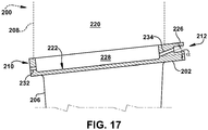
- FIGs. 14-17 show various views of a stator vane 200. More specifically, FIGs. 14-16 show various views of non-limiting examples of stator vane 200 that may be used within turbine 28 of gas turbine system 10 ( see, FIGs. 1 and 2 ).
- Stator vane 200 shown in FIGs. 14 may include substantially similar components and/or features as those discussed herein with respect to stator vanes 40 shown in FIG. 2 .
- stator vane 200 may include an outer platform 202, an inner platform 204 positioned opposite the outer platform 202, and an airfoil 206 positioned between outer platform 202 and inner platform 204, respectively. It is understood that similarly numbered and/or named components may function in a substantially similar fashion. Redundant explanation of these components has been omitted for clarity.
- stator vane 200 may also include a retaining component 208.
- Retaining component 208 is shown in FIG. 14 in phantom as optional. That is, in some non-limiting examples stator vane 200 may include retaining component 208 for coupling and/or positioning stator vane 200 circumferentially about casing 36 of turbine 28 ( see, FIG. 2 ). As shown in the non-limiting example, retaining component 208 may be coupled and/or connected to outer platform 202 of stator vane 200. In other non-limiting examples stator vane 200 may not include retaining component 208 ( see. FIG. 16 ). Rather, outer platform 202 may contact and/or be coupled to distinct portions or components of turbine 28 (e.g., turbine shroud 100) to be positioned and/or secured within turbine 28 during operational.
- turbine 28 e.g., turbine shroud 100
- stator vane 200 may include similar features as those discussed herein with respect to turbine shroud 100 shown in FIGs. 3-9 , that may aid in directing post-cooling fluid exhausted from stator vane 200.
- Stator vane 200 may also include various ends, sides, and/or surfaces.
- stator vane 200 may include a forward end 210 and an aft end 212 positioned opposite forward end 210.
- Forward end 210 may be positioned upstream of aft end 212, such that combustion gases 26 flowing through the flow path (FP) defined within turbine 28 may flow adjacent forward end 210 before flowing by adjacent aft end 212 of stator vane 200.
- stator vane 200 may also include an outer surface 218. More specifically in the non-limiting example where stator vane 200 includes retaining component 208, retaining component 208 may include outer surface 218. Outer surface 218 may face a cooling chamber 220 formed between stator vane 200 and turbine casing 36 ( see, FIG. 2 ).
- outer surface 218 may be positioned, formed, face, and/or directly exposed in cooling chamber 220 formed between retaining component 208 of stator vane 200 and turbine casing 36 of turbine 28.
- cooling chamber 220 formed between stator vane 200 and turbine casing 36 may receive and/or provide cooling fluid to stator vane 200 during operation of turbine 28.
- outer surface 218 of stator vane 200 may also be formed and/or positioned between forward end 210 and aft end 212 of stator vane 200.
- Stator vane 200 may also include inner surface 222 formed opposite outer surface 218. That is, and as shown in the non-limiting example in FIG. 15 , inner surface 222 of stator vane 200 may be formed radially opposite outer surface 218.
- inner surface 222 may include and/or may be at least partially defined by outer platform 202 of stator vane 200, which faces the hot gas flow path (FP) of combustion gases 26 flowing through turbine 28 ( see, FIG. 2 ).
- inner surface 222 at least partially defined by outer platform 202 of stator vane 200 may at least partially form and/or define at least one cooling passage within stator vane 200/retaining component 208 that may be used to cool retaining component 208 and/or outer platform 202 during operation of turbine 28.
- Stator vane 200 may include an impingement portion 224.
- Impingement portion 224 may be formed as an integral portion of stator vane 200.
- Impingement portion 224 may include outer surface 218, and/or outer surface 218 may be formed on impingement portion 224 of stator vane 200.
- Impingement portion 224 of stator vane 200 may be formed, positioned, and/or extend between forward end 210 and aft end 212 of stator vane 200. As shown in FIG. 15 , impingement portion 224 may be positioned radially adjacent inner surface 222 and/or may positioned radially adjacent outer platform 202.
- Impingement portion 224 of stator vane 200 may at least partially form and/or define at least one cooling passage within stator vane 200, as discussed herein.
- stator vane 200 may also include a flange 226.
- Flange 226 may extend from aft end 212 of stator vane 200. More specifically, flange 226 may extend (substantially) axially from aft end 212 of retaining component 208, and may be positioned radially adjacent outer platform 202. In the non-limiting example shown in FIG. 15 , flange 226 may be substantially planar, axially oriented, and/or substantially parallel with axis (A). As shown, flange 226 may be formed integral with aft end 212 of retaining component 208 for stator vane 200.
- flange 226 may be formed as a distinct feature and/or component that may subsequently installed and/or affixed to aft end 212 of retaining component 208, prior to stator vane 200 be implemented within gas turbine system 10 ( see. FIGs. 1 and 2 ). Additionally as shown in the non-limiting example of FIG. 15 , outer platform 202 of stator vane 200 may extend axially beyond and/or may extend axially further than flange 226. In other non-limiting examples, flange 226 may extend axially beyond outer platform 202, or may extend axial from aft end 212 to be radially aligned with outer platform 202 (not shown).
- flange 226 may direct post-cooling fluid from stator vane 200 away from casing 36 and/or may block the post-cooling fluid from stator vane 200 from contacting casing 36. Additionally, and as discussed herein, flange 226 may also absorb heat transferred to the post-cooling fluid that was previously used to cool stator vane 200.
- Stator vane 200 may also include at least one cooling passage formed therein for cooling stator vane 200 during operation of turbine 28 of gas turbine system 10.
- stator vane 200 may include a cooling passage 228 formed, positioned, and/or extending within stator vane 200. More specifically, cooling passage 228 of stator vane 200 may extend within retaining component 208 of stator vane 200 between and/or adjacent forward end 210, and aft end 212. Additionally, and as shown in FIG. 15 , cooling passage 228 may extend within stator vane 200 (radially) between and/or may be at least partially defined by outer platform 202 and impingement portion 224. Cooling passage 228 may also be positioned and/or formed substantially adjacent inner surface 222.
- cooling passage 228 may receive cooling fluid from cooling chamber 220 to cool stator vane 200.
- the size (e.g., radial-opening height) of cooling passage 228 may be dependent on a variety of factors including, but not limited to, the size of stator vane 200, the thickness of outer platform 202 and/or impingement portion 224, the cooling demand for stator vane 200, and/or so on.
- stator vane 200 may also include a plurality of impingement openings 230 formed therethrough. That is, and as shown in FIG. 15 , stator vane 200 may include a plurality of impingement openings 230 formed through outer surface 218, and more specifically impingement portion 224, of stator vane 200. The plurality of impingement openings 230 formed through outer surface 218 and/or impingement portion 224 may fluidly couple cooling passage 228 to cooling chamber 220. As discussed herein, during operation of gas turbine system 10 ( see, FIG. 1 ) cooling fluid flowing through cooling chamber 220 may pass or flow through the plurality of impingement openings 230 to cooling passage 228 to substantially cool stator vane 200.
- stator vane 200 may include larger or smaller impingement openings 230, and/or may include more or less impingement openings 230 formed therein.
- the plurality of impingement openings 230 are shown to be substantially uniform in size and/or shape, it is understood that each of the plurality of impingement openings 230 formed on stator vane 200 may include distinct sizes and/or shapes.
- the size, shapes, and/or number of impingement openings 230 formed in stator vane 200 may be dependent, at least in part on the operational characteristics (e.g., exposure temperature, exposure pressure, position within turbine casing 36, and the like) of gas turbine system 10 during operation. Additionally, or alternatively, the size, shapes, and/or number of impingement openings 230 formed in stator vane 200 may be dependent, at least in part on the characteristics of stator vane 200/cooling passage 228.
- Stator vane 200 may include a plurality of forward end exhaust conduits 232 (one shown).
- the plurality of forward end exhaust conduits 232 may be in fluid communication with cooling passage 228. More specifically, the plurality of forward end exhaust conduits 232 may each be in fluid communication with and may extend axially from cooling passage 228 of stator vane 200. In the non-limiting example shown in FIG. 15 , the plurality of forward end exhaust conduits 232 may extend through retaining component 208 of stator vane 200, from cooling passage 228 to forward end 210. In addition to being in fluid communication with cooling passage 228, the plurality of forward end exhaust conduits 232 may be in fluid communication with an area within turbine 28 ( see, FIG.
- the plurality of forward end exhaust conduits 232 may discharge cooling fluid (e.g., post-cooling fluid) from cooling passage 228, adjacent and upstream of forward end 210 of stator vane 200.
- cooling fluid e.g., post-cooling fluid
- stator vane 200 may include any number of forward end exhaust conduits 232 formed therein, and in fluid communication with cooling passage 228. Additionally, although shown as being substantially round/circular and linear, it is understood that forward end exhaust conduit(s) 232 may be non-round and/or non-linear openings, channels and/or manifolds. Where forward end exhaust conduit(s) 232 are formed to be non-round and/or non-linear, the direction of flow of the cooling fluid may vary to improve the cooling of forward end 210 of stator vane 200. Furthermore, forward end exhaust conduit(s) 232 may also have varying sizes between each forward end exhaust conduit 232 dependent on the cooling needs of stator vane 200 during operation.
- stator vane 200 may include a plurality of aft end exhaust conduits 234.
- the plurality of aft end exhaust conduits 234 may be in fluid communication with cooling passage 228, and in turn may be in fluid communication with cooling chamber 220. More specifically, the plurality of aft end exhaust conduits 234 may be in fluid communication with and may extend from cooling passage 228 of stator vane 200. Additionally, and as a result of cooling passage 228 being in direct fluid communication with cooling chamber 220, each of the plurality of aft end exhaust conduits 234 may also be in fluid communication with cooling chamber 220. As shown in FIG.
- the plurality of aft end exhaust conduits 234 may extend through retaining component 208 of stator vane 200, from cooling passage 228 to and through aft end 212 of stator vane 200. Additionally, the plurality of aft end exhaust conduits 234 may also extend and/or may be positioned radial between outer platform 202 (e.g., base portion 236) and flange 226 of stator vane 200. In the non-limiting example, the plurality of aft end exhaust conduits 234 may also extend through stator vane 200 at an angle ( ⁇ ). That is, and as shown in FIG.
- the plurality of aft end exhaust conduits 234 may be angled radially outward from cooling passage 228 toward flange 226, and/or may extend through stator vane 200 at a radial angle ( ⁇ ).
- the plurality of aft end exhaust conduits 234 may also be in fluid communication with an area of turbine 28 ( see, FIG. 2 ) that may be positioned downstream of and axially adjacent aft end 212 of stator vane 200.
- the plurality of aft end exhaust conduits 234 may discharge cooling fluid (e.g., post-cooling fluid) from cooling passage 228, adjacent and downstream of aft end 212 of stator vane 200.
- stator vane 200 may include any number of aft end exhaust conduits 234 formed therein, and in fluid communication with cooling passage 228, and in turn in fluid communication with cooling chamber 220. Additionally, although shown as being substantially round/circular and linear, it is understood that aft end exhaust conduits 234 may be non-round and/or non-linear openings, channels and/or manifolds. Where aft end exhaust conduit(s) 234 are formed to be non-round and/or non-linear, the direction of flow of the cooling fluid may vary to improve the cooling of aft end 212 of stator vane 200. Furthermore, aft end exhaust conduit(s) 234 may also have varying sizes between each aft end exhaust conduits 234 dependent on the cooling needs of stator vane 200 during operation.
- cooling fluid may flow through and cool stator vane 200. More specifically, as stator vane 200 is exposed to combustion gases 26 flowing through the hot gas flow path of turbine 28 ( see, FIG. 2 ) during operation of gas turbine system 10 and increases in temperature, cooling fluid (CF) may be provided to and/or may flow through cooling passage 228 formed between outer platform 202 and impingement portion 224 to cool retaining component 208 and/or outer platform 202 of stator vane 200. With respect to FIG. 15 , the various arrows may represent and/or may illustrates the flow path of the cooling fluid (CF) as it flows through stator vane 200.
- cooling fluid (CF) may first flow from cooling chamber 220 to cooling passage 228 via the plurality of impingement openings 230 formed through outer surface 218 and/or impingement portion 224 of stator vane 200.
- the cooling fluid (CF) flowing into/through cooling passage 228 may cool and/or receive heat from outer surface 218/impingement portion 224 and/or inner surface 222/outer platform 202.
- the cooling fluid (CF) may be dispersed and/or may flow axially toward one of forward end 210 or aft end 212 of stator vane 200. Additionally, the cooling fluid (CF) may be dispersed and/or may flow circumferentially toward one of first side 110 or second side 112 of stator vane 200.
- cooling fluid (CF) within cooling passage 228 may flow to through respective exhaust conduits 232, 234.
- a portion of the cooling fluid (CF) that flows axially through cooling passage 228 toward forward end 210 may be dispensed and/or exhausted from stator vane 200 via the plurality of forward end exhaust conduits 232 in fluid communication with cooling passage 228 and formed or extending through forward end 210 of stator vane 200.
- the portion of the cooling fluid (CF) that flows axially through cooling passage 228 toward aft end 212 may be dispensed and/or exhausted from stator vane 200 via the plurality of aft end exhaust conduits 234 in fluid communication with cooling passage 228 and formed or extending through aft end 212 of stator vane 200.
- the cooling fluid e.g., post-cooling fluid
- the cooling fluid may flow toward, contact, and/or may be redirected by flange 226 of stator vane 200.
- the cooling fluid may be exhausted from aft end exhaust conduits 234 directly toward flange 226 as well.
- Flange 226 may than direct the post-cooling fluid radially back toward outer platform 202 and/or radially away distinct portions of retaining component 208 of stator vane 200/casing 36 ( see, FIG. 2 ). Additionally, flange 226 may prevent the post-cooling fluid exhausted from aft end exhaust conduits 234 from flowing radially around flange 226 and away from outer platform 202.
- flange 226 may prevent the post-cooling fluid from flowing over and/or contacting components of turbine 28 positioned radially adjacent flange 226 and radially opposite or outward from outer platform 202 of stator vane 200 (e.g., casing 26) ( see. FIG. 2 ). Furthermore, flange 226 may also absorb and/or dissipate at least a portion of the heat transferred to post-cooling fluid from stator vane 200 while the cooling fluid flows through cooling passage 228.
- the post-cooling fluid that may contact and/or be redirected by flange 226 may continue to flow axially away from/downstream of stator vane 200 toward a downstream component of turbine 28 (e.g., turbine shroud 100).
- the downstream component may utilized the post-cooling fluid from stator vane 200 for additional processing (e.g., for cooling purposes).
- FIG. 16 shows another non-limiting example of stator vane 200.
- stator vane 200 may or not include retaining component 208 (shown in phantom as optional).
- the features used to cool stator vane 200 may be formed and/or positioned directly within outer platform 202 of stator vane 200. That is, and as shown in FIG. 16 , outer surface 218, inner surface 222, impingement portion 224, cooling passage 228, and openings 230 may all be formed in and/or integrally with outer platform 202 of stator vane 200.
- flange 226 of stator vane 200 may be formed integrally with outer platform 202.
- flange 226 may be formed integrally within outer platform 202, and radially above or adjacent base portion 236 of outer platform 202 that may be exposed to hot gas during operational of turbine 28 ( see, FIG. 2 ), as discussed herein. Additionally as shown in FIG. 16 , flange 226 may extend substantially axially from cooling passage 228 formed in outer platform 202.
- exhaust conduits 232, 234 may be formed within and may extend through outer platform 202. More specifically, the plurality of forward end exhaust conduits 232 may extend through forward end 210 of outer platform 202 to exhaust cooling fluid from cooling chamber 228 formed within outer platform 202. Additionally, each of the plurality of aft end exhaust conduits 234 may extend through aft end 212 of outer platform 202 for stator vane 200. In the non-limiting example, the plurality of aft end exhaust conduits 234 may extend between and/or through aft end 212 of outer platform 202 radially between base portion 236 of outer platform 202 and flange 226; also formed integral with outer platform 202.
- the plurality of aft end exhaust conduits 234 may extend through aft end 212 of outer platform 202 at a radial angle ( ⁇ ) upward toward flange 226, such that the cooling fluid may be exhausted from aft end exhaust conduits 234 directly toward flange 226.
- FIG. 17 shows an additional, non-limiting example of stator vane 200.
- cooling passage 228 formed in a portion of outer platform 202 of stator vane 200 may be entirely exposed and/or open to cooling chamber 220 of stator vane 200.
- cooling chamber 220 may be formed within retaining component 208 (shown in phantom as optional).
- cooling chamber 220 may represent a space between outer platform 202 of stator vane 200 and casing 36 of turbine 28 ( see, FIG. 2 ).
- cooling fluid (CF) used to cool outer platform 202 of stator vane 200 may flow directly from cooling chamber 220 to cooling passage 228, and subsequently exhausted from conduits 232, 234, as discussed herein.
- CF cooling fluid
- hot gas path components e.g., turbine shrouds, stator vanes
- the hot gas path components including the angled exhaust conduits and aft end flange prevents post-cooling fluid from being undesirably, exhausted directly toward and/or from undesirably contacting a turbine casing or coupling component of a turbine that secures the hot gas path components therein.
- Approximating language may be applied to modify any quantitative representation that could permissibly vary without resulting in a change in the basic function to which it is related. Accordingly, a value modified by a term or terms, such as “about,” “approximately” and “substantially,” are not to be limited to the precise value specified. In at least some instances, the approximating language may correspond to the precision of an instrument for measuring the value.
- range limitations may be combined and/or interchanged, such ranges are identified and include all the sub-ranges contained therein unless context or language indicates otherwise. "Approximately” as applied to a particular value of a range applies to both values, and unless otherwise dependent on the precision of the instrument measuring the value, may indicate +/- 10% of the stated value(s).
Landscapes
- Engineering & Computer Science (AREA)
- Mechanical Engineering (AREA)
- General Engineering & Computer Science (AREA)
- Chemical & Material Sciences (AREA)
- Combustion & Propulsion (AREA)
- Turbine Rotor Nozzle Sealing (AREA)
Abstract
Description
- The disclosure relates generally to hot gas path components for turbine systems, and more particularly, to turbine shrouds and stator vanes that include a plurality of aft end exhaust conduits and aft end flanges.
- Conventional turbomachines, such as gas turbine systems, are utilized to generate power for electric generators. In general, gas turbine systems generate power by passing a fluid (e.g., hot gas) through a turbine component of the gas turbine system. More specifically, inlet air may be drawn into a compressor and may be compressed. Once compressed, the inlet air is mixed with fuel to form a combustion product, which may be ignited by a combustor of the gas turbine system to form the operational fluid (e.g., hot gas) of the gas turbine system. The fluid may then flow through a fluid flow path for rotating a plurality of rotating blades and rotor or shaft of the turbine component for generating the power. The fluid may be directed through the turbine component via the plurality of rotating blades and a plurality of stationary nozzles or vanes positioned between the rotating blades. As the plurality of rotating blades rotate the rotor of the gas turbine system, a generator, coupled to the rotor, may generate power from the rotation of the rotor.
- To improve operational efficiencies turbine components may include turbine shrouds and/or nozzle bands to further define the flow path of the operational fluid. Turbine shrouds, for example, may be positioned radially adjacent rotating blades of the turbine component and may direct the operational fluid within the turbine component and/or define the outer bounds of the fluid flow path for the operational fluid. During operation, turbine shrouds may be exposed to high temperature operational fluids flowing through the turbine component. Over time and/or during exposure, the turbine shrouds may undergo undesirable thermal expansion. The thermal expansion of turbine shrouds may result in damage to the shrouds and/or may not allow the shrouds to maintain a seal within the turbine component for defining the fluid flow path for the operational fluid. When the turbine shrouds become damaged or no longer form a satisfactory seal within the turbine component, the operational fluid may leak from the flow path, which in turn reduces the operational efficiency of the turbine component and the entire turbine system.
- To minimize thermal expansion, turbine shrouds are typically cooled. One conventional process for cooling turbine shrouds includes impingement cooling. Impingement cooling utilizes holes or apertures formed through the turbine shroud to provide cooling air to various portions of the turbine shroud during operation. However, these conventional processes present new issues that reduce operational efficiencies for the system. For example, while the turbine shrouds are cooled during operation, the fluid (e.g., air) used to cool the shroud absorbs the heat. When discharged from the shroud, this heated cooling fluid may flow directly adjacent, be exposed to, and/or contact portions of the turbine casing that may support the shroud and other various components of the turbine. The casing and/or the components that support the shroud and/or other various components of the turbine may be negatively impacted or affected by exposure to the heightened temperature cooling fluid. That is, exposure to the cooling fluid with the heightened temperature may undesirably and prematurely degrade the material forming the casing, which in turn reduces the operational life.
- A first aspect of the disclosure provides a turbine shroud coupled to a turbine casing of a turbine system. The turbine shroud includes: a forward end including a first hook coupled to the turbine casing; an aft end positioned opposite the forward end, the aft end including a second hook coupled to the turbine casing; a base portion extending between the forward end and the aft end and positioned radially opposite the first hook and the second hook coupled to the turbine casing, the base portion including an inner surface facing a hot gas flow path for the turbine system; a flange extending from the aft end and positioned radially between the base portion and the second hook; a cooling passage positioned within the base portion, adjacent the inner surface; and at least one aft end exhaust conduit in fluid communication with the cooling passage, the at least one aft end exhaust conduit extending through the aft end, radially between the base portion and the flange.
- A second aspect of the disclosure provides a turbine system including: a turbine casing; and a first stage positioned within the turbine casing, the first stage including: a plurality of turbine blades positioned within the turbine casing and circumferentially about a rotor; a plurality of stator vanes positioned within the turbine casing, downstream of the plurality of turbine blades; and a plurality of turbine shrouds positioned radially adjacent the plurality of turbine blades and upstream of the plurality of stator vanes, each of the plurality of turbine shrouds including: a forward end including a first hook coupled to the turbine casing; an aft end positioned opposite the forward end, the aft end including a second hook coupled to the turbine casing; a base portion extending between the forward end and the aft end and positioned radially opposite the first hook and the second hook coupled to the turbine casing, the base portion including an inner surface facing a hot gas flow path for the turbine system; a flange extending from the aft end and positioned radially between the base portion and the second hook; a cooling passage positioned within the base portion, adjacent the inner surface; and at least one aft end exhaust conduit in fluid communication with the cooling passage, the at least one aft end exhaust conduit extending through the aft end, radially between the base portion and the flange.
- A third aspect of the disclosure provides a stator vane positioned within a turbine casing of a turbine system. The stator vane includes: a forward end; an aft end positioned opposite the forward end; a base portion extending between the forward end and the aft end and positioned radially opposite the turbine casing, the base portion including an inner surface facing a hot gas flow path for the turbine system; a flange extending from the aft end and positioned radially between the base portion and the turbine casing; a cooling passage positioned adjacent the base portion and the inner surface; and at least one aft end exhaust conduit in fluid communication with the cooling passage, the at least one aft end exhaust conduit extending through the aft end, radially between the base portion and the flange.
- The illustrative aspects of the present disclosure are designed to solve the problems herein described and/or other problems not discussed.
- These and other features of this disclosure will be more readily understood from the following detailed description of the various aspects of the disclosure taken in conjunction with the accompanying drawings that depict various embodiments of the disclosure, in which:
-
FIG. 1 shows a schematic diagram of a gas turbine system, according to embodiments of the disclosure; -
FIG. 2 shows a side view of a portion of a turbine of the gas turbine system ofFIG. 1 including a turbine blade, a stator vane, a rotor, a casing, and a turbine shroud, according to embodiments of the disclosure; -
FIG. 3 shows an isometric view of the turbine shroud ofFIG. 2 , according to embodiments of the disclosure; -
FIG. 4 shows a top view of the turbine shroud ofFIG. 3 , according to embodiments of the disclosure; -
FIG. 5 shows a side view of the turbine shroud ofFIG. 3 , according to embodiments of the disclosure; -
FIG. 6 shows a cross-sectional side view of the turbine shroud taken along line 6-6 inFIG. 4 , according to embodiments of the disclosure; -
FIGs. 7-9 show cross-sectional side views of a turbine shroud, according to additional embodiments of the disclosure; -
FIG. 10 shows an enlarged side view of the portion of the turbine of the gas turbine system ofFIG. 2 including the turbine shroud, according to embodiments of the disclosure; -
FIG. 11 shows a top view of a turbine shroud, according to further embodiments of the disclosure; -
FIG. 12 shows a cross-sectional side view of the turbine shroud taken along line 12-12 inFIG. 11 , according to embodiments of the disclosure; -
FIG. 13 shows a top view of a turbine shroud, according to another embodiment of the disclosure; -
FIG. 14 shows a side view of a stator vane, according to embodiments of the disclosure; -
FIG. 15 shows a cross-sectional side view of the stator vane taken along line 15-15 inFIG. 14 , according to embodiments of the disclosure; and -
FIGs. 16 and17 show cross-sectional side views of the stator vane ofFIG. 14 , according to further embodiments of the disclosure. - It is noted that the drawings of the disclosure are not to scale. The drawings are intended to depict only typical aspects of the disclosure, and therefore should not be considered as limiting the scope of the disclosure. In the drawings, like numbering represents like elements between the drawings.
- As an initial matter, in order to clearly describe the current disclosure it will become necessary to select certain terminology when referring to and describing relevant machine components within the scope of this disclosure. When doing this, if possible, common industry terminology will be used and employed in a manner consistent with its accepted meaning. Unless otherwise stated, such terminology should be given a broad interpretation consistent with the context of the present application and the scope of the appended claims. Those of ordinary skill in the art will appreciate that often a particular component may be referred to using several different or overlapping terms. What may be described herein as being a single part may include and be referenced in another context as consisting of multiple components. Alternatively, what may be described herein as including multiple components may be referred to elsewhere as a single part.
- In addition, several descriptive terms may be used regularly herein, and it should prove helpful to define these terms at the onset of this section. These terms and their definitions, unless stated otherwise, are as follows. As used herein, "downstream" and "upstream" are terms that indicate a direction relative to the flow of a fluid, such as the working fluid through the turbine engine or, for example, the flow of air through the combustor or coolant through one of the turbine's component systems. The term "downstream" corresponds to the direction of flow of the fluid, and the term "upstream" refers to the direction opposite to the flow. The terms "forward" and "aft," without any further specificity, refer to directions, with "forward" referring to the front or compressor end of the engine, and "aft" referring to the rearward or turbine end of the engine. Additionally, the terms "leading" and "trailing" may be used and/or understood as being similar in description as the terms "forward" and "aft," respectively. It is often required to describe parts that are at differing radial, axial and/or circumferential positions. The "A" axis represents an axial orientation. As used herein, the terms "axial" and/or "axially" refer to the relative position/direction of objects along axis A, which is substantially parallel with the axis of rotation of the turbine system (in particular, the rotor section). As further used herein, the terms "radial" and/or "radially" refer to the relative position/direction of objects along a direction "R" (see,
FIG. 1 ), which is substantially perpendicular with axis A and intersects axis A at only one location. Finally, the term "circumferential" refers to movement or position around axis A (e.g., direction "C"). - As indicated above, the disclosure provides hot gas path components for turbine systems, and more particularly, to turbine shrouds and stator vanes that include a plurality of aft end exhaust conduits and aft end flanges.
- These and other embodiments are discussed below with reference to
FIGs. 1-17 . However, those skilled in the art will readily appreciate that the detailed description given herein with respect to these Figures is for explanatory purposes only and should not be construed as limiting. -
FIG. 1 shows a schematic view of an illustrativegas turbine system 10.Gas turbine system 10 may include acompressor 12.Compressor 12 compresses an incoming flow ofair 18.Compressor 12 delivers a flow ofcompressed air 20 to a combustor 22. Combustor 22 mixes the flow ofcompressed air 20 with a pressurized flow offuel 24 and ignites the mixture to create a flow ofcombustion gases 26. Although only a single combustor 22 is shown,gas turbine system 10 may include any number of combustors 22. The flow ofcombustion gases 26 is in turn delivered to aturbine 28, which typically includes a plurality of turbine blades including airfoils (see,FIG. 2 ) and stator vanes (see,FIG. 2 ). The flow ofcombustion gases 26 drivesturbine 28, and more specifically the plurality of turbine blades ofturbine 28, to produce mechanical work. The mechanical work produced inturbine 28 drivescompressor 12 via arotor 30 extending throughturbine 28, and may be used to drive anexternal load 32, such as an electrical generator and/or the like. -
Gas turbine system 10 may also include anexhaust frame 34. As shown inFIG. 1 ,exhaust frame 34 may be positioned adjacent toturbine 28 ofgas turbine system 10. More specifically,exhaust frame 34 may be positioned adjacent toturbine 28 and may be positioned substantially downstream ofturbine 28 and/or the flow ofcombustion gases 26 flowing from combustor 22 toturbine 28. As discussed herein, a portion (e.g., outer casing) ofexhaust frame 34 may be coupled directly to an enclosure, shell, or casing 36 ofturbine 28. - Subsequent to
combustion gases 26 flowing through and drivingturbine 28,combustion gases 26 may be exhausted, flow-through and/or discharged throughexhaust frame 34 in a flow direction (D). In the non-limiting example shown inFIG. 1 ,combustion gases 26 may flow throughexhaust frame 34 in the flow direction (D) and may be discharged from gas turbine system 10 (e.g., to the atmosphere). In another non-limiting example wheregas turbine system 10 is part of a combined cycle power plant (e.g., including gas turbine system and a steam turbine system),combustion gases 26 may discharge fromexhaust frame 34, and may flow in the flow direction (D) into a heat recovery steam generator of the combined cycle power plant. - Turning to
FIG. 2 , a portion ofturbine 28 is shown. Specifically,FIG. 2 shows a side view of a portion ofturbine 28 including a stage of turbine blades 38 (one shown), and a stage of stator vanes 40 (one shown) positioned within casing 36 ofturbine 28. As discussed herein, each stage (e.g., first stage, second stage (not shown), third stage (not shown)) ofturbine blades 38 may include a plurality ofturbine blades 38 that may be coupled to and positioned circumferentially around or aboutrotor 30 and may be driven bycombustion gases 26 to rotaterotor 30. As show, the plurality ofturbine blades 38 may also extend radially fromrotor 30. Additionally, each stage (e.g., first stage, second stage (not shown), third stage (not shown)) ofstator vanes 40 may include a plurality of stator vanes that may be coupled to and/or positioned circumferentially about casing 36 ofturbine 28 via a retainingcomponent 41 extending from casing 36. In the non-limiting example shown inFIG. 2 ,stator vanes 40 may include a plurality of hot gas path (HGP) components including and/or be formed as anouter platform 42 coupled directly to retainingcomponent 41, and aninner platform 44 positioned opposite theouter platform 42.Stator vanes 40 ofturbine 28 may also include anairfoil 45 positioned betweenouter platform 42 andinner platform 44.Outer platform 42 andinner platform 44 ofstator vanes 40 may define a flow path (FP) for thecombustion gases 26 flowing overstator vanes 40. As discussed herein,stator vanes 40, and more specificallyouter platform 42, may be positioned directly adjacent and downstream of a turbine shroud ofturbine 28. - Each
turbine blade 38 ofturbine 28 may include anairfoil 46 extending radially fromrotor 30 and positioned within the flow path (FP) ofcombustion gases 26 flowing throughturbine 28. Eachairfoil 46 may includetip portion 48 positioned radially oppositerotor 30.Turbine blade 38 may also include aplatform 50 positioned oppositetip portion 48 ofairfoil 46. In a non-limiting example,platform 50 may partially define a flow path forcombustion gases 26 forturbine blades 38.Turbine blades 38 andstator vanes 40 may also be positioned axially adjacent to one another withincasing 36. In the non-limiting example shown inFIG. 2 ,stator vanes 40 may be positioned axially adjacent and downstream ofturbine blades 38. Not allturbine blades 38,stator vanes 40 and/or all ofrotor 30 ofturbine 28 are shown for clarity. Additionally, although only a portion of a single stage ofturbine blades 38 andstator vanes 40 ofturbine 28 are shown inFIG. 2 ,turbine 28 may include a plurality of stages of turbine blades and stator vanes, positioned axially throughout casing 36 ofturbine 28. -
Turbine 28 of gas turbine system 10 (see,FIG. 1 ) may also include a plurality ofturbine shrouds 100 included withinturbine 28.Turbine 28 may include a stage of turbine shrouds 100 (one shown). Turbine shrouds 100 may correspond with the stage ofturbine blades 38 and/or the stage ofstator vanes 40. That is, and as discussed herein, the stage ofturbine shrouds 100 may be positioned withinturbine 28 adjacent the stage ofturbine blades 38 and/or the stage ofstator vanes 40 to interact with and provide a seal in and/or define the flow path (FP) ofcombustion gases 26 flowing throughturbine 28. In the non-limiting example shown inFIG. 2 , the stage ofturbine shrouds 100 may be positioned radially adjacent and/or may substantially surround or encircle the stage ofturbine blades 38. Turbine shrouds 100 may be positioned radiallyadjacent tip portion 48 ofairfoil 46 forturbine blade 38. Additionally in the non-limiting example, turbine shrouds 100 may also be positioned axially adjacent and/or upstream ofstator vanes 40 ofturbine 28. Turbine shrouds 100 may also be positioned between two adjacent stages of stator vanes that may surround and/or be positioned on either axially side of a single stage of turbine blades. - The stage of turbine shrouds may include a plurality of
turbine shrouds 100 that may be coupled directly to and/or positioned circumferentially about casing 36 ofturbine 28. In the non-limiting example shown inFIG. 2 , turbine shrouds 100 may be coupled directly to casing 36 viacoupling component 52 extending radially inward (e.g., toward rotor 30) from casing 36 ofturbine 28. As discussed herein,coupling component 52 may include anopening 54 that may be configured to be coupled to and/or receive fasteners or hooks (see,FIG. 3 ) ofturbine shrouds 100 to couple, position, and/orsecure turbine shrouds 100 to casing 36 ofturbine 28. In a non-limiting example,coupling component 52 may be coupled and/or fixed to casing 36 ofturbine 28. More specifically,coupling component 52 may be circumferentially disposed around casing 36, and may be positioned radiallyadjacent turbine blades 38. In another non-limiting example,coupling component 52 may be formed integral with and/or may be a part ofcasing 36 for coupling, positioning, and/or securingturbine shrouds 100 directly tocasing 36. Similar toturbine blades 38 and/orstator vanes 40, although only a portion of the stage ofturbine shrouds 100 ofturbine 28 is shown inFIG. 2 ,turbine 28 may include a plurality of stages ofturbine shrouds 100, positioned axially throughout casing 36 ofturbine 28 and coupled to casing 26 usingcoupling component 52. - Turning to
FIGs. 3-6 show various views ofturbine shroud 100 ofturbine 28 forgas turbine system 10 ofFIG. 1 . Specifically,FIG. 3 shows an isometric view ofturbine shroud 100,FIG. 4 shows a top view ofturbine shroud 100,FIG. 5 shows a side view ofturbine shroud 100, andFIG. 6 shows a cross-sectional side view ofturbine shroud 100. - In the non-limiting example shown,
turbine shroud 100 may include a unitary body. That is, and as shown inFIGs. 3-6 ,turbine shroud 100 may include and/or be formed as unitary body such thatturbine shroud 100 is a single, continuous, and/or non-disjointed component or part. In the non-limiting example shown inFIGs. 3-6 , becauseturbine shroud 100 is formed from unitary body,turbine shroud 100 may not require the building, joining, coupling, and/or assembling of various parts to completely formturbine shroud 100, and/or may not require building, joining, coupling, and/or assembling of various parts beforeturbine shroud 100 can be installed and/or implemented within turbine system 10 (see,FIG. 2 ). Rather, once single, continuous, and/or non-disjointed unitary body forturbine shroud 100 is built, as discussed herein,turbine shroud 100 may be immediately installed withinturbine system 10. - The unitary body of
turbine shroud 100, and the various components and/or features ofturbine shroud 100, may be formed using any suitable additive manufacturing process(es) and/or method. For example,turbine shroud 100 including a unitary body may be formed by direct metal laser melting (DMLM) (also referred to as selective laser melting (SLM)), direct metal laser sintering (DMLS), electronic beam melting (EBM), stereolithography (SLA), binder jetting, or any other suitable additive manufacturing process(es). Additionally, the unitary body ofturbine shroud 100 may be formed from any material that may be utilized by additive manufacturing process(es) to formturbine shroud 100, and/or capable of withstanding the operational characteristics (e.g., exposure temperature, exposure pressure, and the like) experienced byturbine shroud 100 withingas turbine system 10 during operation. - In another non-limiting example (see,
FIG. 9 )turbine shroud 100 may be formed as a plurality of distinct pieces and/or sections that may be built separately and subsequently assembled, coupled, joined, and/or affixed to one another prior to installingturbine shroud 100 withingas turbine system 10.Turbine shroud 100 may be assembled using any suitable technique or process known to join/form components including, but not limited to, welding, brazing, melting, coupling, and so on. Additionally,turbine shroud 100 formed from distinct sections and/or pieces may be formed from any material that may undergo the processes for joining/formingturbine shroud 100 from distinct pieces, and is capable of withstanding the operational characteristics (e.g., exposure temperature, exposure pressure, and the like) experienced byturbine shroud 100 withingas turbine system 10 during operation. -
Turbine shroud 100 may also include various ends, sides, and/or surfaces. For example, and as shown inFIGs. 3 and4 ,turbine shroud 100 may include aforward end 102 and anaft end 104 positioned oppositeforward end 102.Forward end 102 may be positioned upstream ofaft end 104, such thatcombustion gases 26 flowing through the flow path (FP) defined withinturbine 28 may flow adjacentforward end 102 before flowing by adjacentaft end 104 ofturbine shroud 100. As shown inFIGs. 3 and4 ,forward end 102 may includefirst hook 106 configured to be coupled to and/or engagecoupling component 52 ofcasing 36 forturbine 28 to couple, position, and/orsecure turbine shrouds 100 within casing 36 (see,FIG. 2 ). Additionally,aft end 104 may includesecond hook 108 positioned and/or formed onturbine shroud 100 oppositefirst hook 106. Similar tofirst hook 106,second hook 108 may be configured to be coupled to and/or engagecoupling component 52 ofcasing 36 forturbine 28 to couple, position, and/orsecure turbine shrouds 100 within casing 36 (see,FIG. 2 ). - Additionally,
turbine shroud 100 may also include a first slash face or side 110 (hereafter, "first side 110"), and a second slash face or side 112 (hereafter, "second side 112") positioned oppositefirst side 110. As shown inFIGs. 3 and4 ,first side 110 andsecond side 112, each of which may be formed or positioned proximate toforward end 102 andaft end 104, as well as extend and/or be positioned betweenforward end 102 andaft end 104. - As shown in
FIGs. 3-5 turbine shroud 100 may also include anouter surface 120.Outer surface 120 may face a cooling chamber 122 (see,FIG. 5 ) formed betweenturbine shroud 100 and turbine casing 36 (see,FIG. 2 ). More specifically,outer surface 120 may be positioned, formed, face, and/or directly exposed in coolingchamber 122 formed betweenturbine shroud 100 andturbine casing 36 ofturbine 28. In a non-limiting example, coolingchamber 122 may be at least partially defined by opening 54 ofcoupling component 52 forcasing 36. As discussed herein, coolingchamber 122 formed betweenturbine shroud 100 andturbine casing 36 may receive and/or provide cooling fluid toturbine shroud 100 during operation ofturbine 28. In addition to facing coolingchamber 122,outer surface 120 ofturbine shroud 100 may also be formed and/or positioned betweenforward end 102 andaft end 104, as well asfirst side 110 andsecond side 112, respectively. -
Turbine shroud 100 may also includeinner surface 124 formed oppositeouter surface 120. That is, and as shown in the non-limiting example inFIGs. 3 and5 ,inner surface 124 ofturbine shroud 100 may be formed radially oppositeouter surface 120. Briefly returning toFIG. 2 , and with continued reference toFIGs. 3 and5 ,inner surface 124 may face the hot gas flow path (FP) ofcombustion gases 26 flowing through turbine 28 (see,FIG. 2 ). More specifically,inner surface 124 may be positioned, formed, face, and/or directly exposed to the hot gas flow path (FP) ofcombustion gases 26 flowing throughturbine casing 36 ofturbine 28 forgas turbine system 10. Additionally,inner surface 124 ofturbine shroud 100 may be positioned radiallyadjacent tip portion 48 of airfoil 42 (see,FIG. 2 ).Inner surface 124 may be formed and/or extend axially betweenforward end 102 andaft end 104 ofturbine shroud 100. Additionally,inner surface 124 may be formed and/or extend circumferentially between opposingsides turbine shroud 100.Inner surface 124 may also be formed radially oppositefirst hook 106 andsecond hook 108, respectively. - Turning to
FIG. 6 , with continued reference toFIGs. 3-5 , additional features ofturbine shroud 100 are now discussed.Turbine shroud 100 may include abase portion 126. As shown inFIG. 6 ,base portion 126 may be formed as an integral portion ofturbine shroud 100. Additionally,base portion 126 may includeinner surface 124, and/orinner surface 124 may be formed onbase portion 126 ofturbine shroud 100.Base portion 126 ofturbine shroud 100 may be formed, positioned, and/or extend betweenforward end 102 andaft end 104, andfirst side 110 andsecond side 112, respectively.Base portion 126 may also be formed integral withfirst side 110 andsecond side 112 ofturbine shroud 100. In the non-limiting example,base portion 126 may also be positioned radially opposite and/or radially inward fromfirst hook 106 andsecond hook 108 ofturbine shroud 100, coupled to turbine casing 36 (see,FIG. 2 ). As discussed herein,base portion 126 ofturbine shroud 100 may at least partially form and/or define at least one cooling passage withinturbine shroud 100. -
Turbine shroud 100 may include animpingement portion 128. Similar tobase portion 126, as shown inFIG. 6 ,impingement portion 128 may be formed as an integral portion ofturbine shroud 100.Impingement portion 128 may includeouter surface 120, and/orouter surface 120 may be formed onimpingement portion 128 ofturbine shroud 100.Impingement portion 128 ofturbine shroud 100 may be formed, positioned, and/or extend betweenforward end 102 andaft end 104, as well asfirst side 110 andsecond side 112, respectively. Additionally, and also similar tobase portion 126,impingement portion 128 may be formed integral withfirst side 110 andsecond side 112 ofturbine shroud 100. As shown inFIG. 6 ,impingement portion 128 may be positioned radiallyadjacent base portion 126 and/or may positioned radially betweenbase portion 126 andfirst hook 106 andsecond hook 108, respectively.Impingement portion 128 ofturbine shroud 100, along withbase portion 126, may at least partially form and/or define at least one cooling passage withinturbine shroud 100, as discussed herein. - As shown in
FIG. 6 ,turbine shroud 100 may also include aflange 130.Flange 130 may extend fromaft end 104 ofturbine shroud 100. More specifically,flange 130 may extend (substantially) axially fromaft end 104, and may be positioned radially betweenbase portion 126 andsecond hook 108 ofturbine shroud 100. Additionally,flange 130 may extend fromaft end 104, (circumferentially) betweenfirst side 110 andsecond side 112. In the non-limiting example shown inFIG. 6 ,flange 130 may be substantially planar, axially oriented, and/or substantially parallel with axis (A) and/orinner surface 124 ofbase portion 126. In other non-limiting examples (see,FIGs. 7 and8 ),flange 130 may be angled and/or may angularly extend fromaft end 104. As shown,flange 130 may be formed integral withaft end 104 ofturbine shroud 100. In another non-limiting example (not shown),flange 130 may be formed as a distinct feature and/or component that may subsequently installed and/or affixed toaft end 104 ofturbine shroud 100, prior toturbine shroud 100 be implemented within gas turbine system 10 (see.FIGs. 1 and2 ). Additionally as shown in the non-limiting example ofFIG. 6 ,base portion 126 ofturbine shroud 100 may extend axially beyond and/or may extend axially further thanflange 130. In other non-limiting examples,flange 130 may extend axially beyond base portion 126 (see,FIG. 9 ), or may extend axial fromaft end 104 to be radially aligned with base portion 126 (not shown). As discussed herein,flange 130 may direct post-cooling fluid fromturbine shroud 100 away from casing 36 and/or coupling component 52 (see,FIGs. 2 and10 ) and/or may block the post-cooling fluid fromturbine shroud 100 from contactingcasing 36 and/orcoupling component 52. Additionally, and as discussed herein,flange 130 may also absorb heat transferred to the post-cooling fluid that was previously used to coolturbine shroud 100. -
Turbine shroud 100 may also include at least one cooling passage formed therein for coolingturbine shroud 100 during operation ofturbine 28 ofgas turbine system 10. As shown inFIGs. 4 and6 ,turbine shroud 100 may include acooling passage 132 formed, positioned, and/or extending withinturbine shroud 100. More specifically, and briefly returning toFIG. 4 , cooling passage 132 (shown in phantom inFIG. 4 ) ofturbine shroud 100 may extend withinturbine shroud 100 between and/or adjacentforward end 102,aft end 104,first side 110, andsecond side 112, respectively. Additionally, and as shown inFIG. 6 , coolingpassage 132 may extend within turbine shroud 100 (radially) between and/or may be at least partially defined bybase portion 126 andimpingement portion 128.Cooling passage 132 may also be positioned and/or formed substantially withinbase portion 126, adjacentinner surface 124. As discussed herein, coolingpassage 132 may receive cooling fluid from coolingchamber 122 to coolturbine shroud 100. The size (e.g., radial-opening height) ofcooling passage 132 may be dependent on a variety of factors including, but not limited to, the size ofturbine shroud 100, the thickness ofbase portion 126 and/orimpingement portion 128, the cooling demand forturbine shroud 100, and/or the geometry or shape offorward end 102 and/oraft end 104 ofturbine shroud 100. - In order to provide
cooling passage 132 with cooling fluid,turbine shroud 100 may also include a plurality ofimpingement openings 134 formed therethrough. That is, and as shown inFIGs. 4 and6 ,turbine shroud 100 may include a plurality ofimpingement openings 134 formed throughouter surface 120, and more specificallyimpingement portion 128, ofturbine shroud 100. The plurality ofimpingement openings 134 formed throughouter surface 120 and/orimpingement portion 128 may fluidly couple coolingpassage 132 to coolingchamber 122. As discussed herein, during operation of gas turbine system 10 (see,FIG. 1 ) cooling fluid flowing through coolingchamber 122 may pass or flow through the plurality ofimpingement openings 134 to coolingpassage 132 to substantiallycool turbine shroud 100. - It is understood that the size and/or number of
impingement openings 134 formed throughouter surface 120 and/orimpingement portion 128, as shown inFIGs. 4 and6 , is merely illustrative. As such,turbine shroud 100 may include larger orsmaller impingement openings 134, and/or may include more or lessimpingement openings 134 formed therein. Additionally, although the plurality ofimpingement openings 134 are shown to be substantially uniform in size and/or shape, it is understood that each of the plurality ofimpingement openings 134 formed onturbine shroud 100 may include distinct sizes and/or shapes. The size, shapes, and/or number ofimpingement openings 134 formed inturbine shroud 100 may be dependent, at least in part on the operational characteristics (e.g., exposure temperature, exposure pressure, position withinturbine casing 36, and the like) ofgas turbine system 10 during operation. Additionally, or alternatively, the size, shapes, and/or number ofimpingement openings 134 formed inturbine shroud 100 may be dependent, at least in part on the characteristics (e.g.,base portion 126 thickness,impingement portion 128 thickness, height of coolingpassage 132, volume of coolingpassage 132, and so on) ofturbine shroud 100/cooling passage 132. - Also shown in
FIGs. 4 and6 ,turbine shroud 100 may include a plurality of forward end exhaust conduits 136 (shown in phantom inFIG. 4 ). The plurality of forwardend exhaust conduits 136 may be in fluid communication withcooling passage 132, and inturn cooling chamber 122. More specifically, the plurality of forwardend exhaust conduits 136 may each be in fluid communication with and may extend axially from coolingpassage 132 ofturbine shroud 100. In the non-limiting example shown inFIG. 6 , the plurality of forwardend exhaust conduits 136 may extend throughturbine shroud 100, from coolingpassage 132 toforward end 102 ofturbine shroud 100. In addition to being in fluid communication withcooling passage 132, the plurality of forwardend exhaust conduits 136 may be in fluid communication with an area within turbine 28 (see,FIG. 2 ) that is positioned upstream and axially aligned withforward end 102 ofturbine shroud 100. During operation, and as discussed herein, the plurality of forwardend exhaust conduits 136 may discharge cooling fluid (e.g., post-cooling fluid) from coolingpassage 132, adjacent and upstream offorward end 102 ofturbine shroud 100. - It is understood that
turbine shroud 100 may include any number of forwardend exhaust conduits 136 formed therein, and in fluid communication withcooling passage 132. Additionally, although shown as being substantially round/circular and linear, it is understood that forward end exhaust conduit(s) 136 may be non-round and/or non-linear openings, channels and/or manifolds. Where forward end exhaust conduit(s) 136 are formed to be non-round and/or non-linear, the direction of flow of the cooling fluid may vary to improve the cooling offorward end 102 ofturbine shroud 100. Furthermore, forward end exhaust conduit(s) 136 may also have varying sizes between each forwardend exhaust conduit 136 dependent on the cooling needs ofturbine shroud 100 during operation. - Also shown in
FIG. 6 ,turbine shroud 100 may include a plurality of aftend exhaust conduits 138. The plurality of aftend exhaust conduits 138 may be in fluid communication withcooling passage 132, and in turn may be in fluid communication withcooling chamber 122. More specifically, the plurality of aftend exhaust conduits 138 may be in fluid communication with and may extend from coolingpassage 132 ofturbine shroud 100. Additionally, and as a result of coolingpassage 132 being in direct fluid communication withcooling chamber 122, each of the plurality of aftend exhaust conduits 138 may also be in fluid communication withcooling chamber 122. As shown inFIG. 6 , the plurality of aftend exhaust conduits 138 may extend throughturbine shroud 100, from coolingpassage 132 to and throughaft end 104 ofturbine shroud 100. Additionally, the plurality of aftend exhaust conduits 138 may also extend and/or may be positioned radial betweenbase portion 126 andflange 130 ofturbine shroud 100. In the non-limiting example, the plurality of aftend exhaust conduits 138 may also extend throughturbine shroud 100 at an angle (α). That is, and as shown inFIG. 6 , the plurality of aftend exhaust conduits 138 may be angled radially outward from coolingpassage 132 towardflange 130, and/or may extend throughturbine shroud 100 at a radial angle (α). The plurality of aftend exhaust conduits 138 may also be in fluid communication with an area of turbine 28 (see,FIG. 2 ) that may be positioned downstream of and axially adjacentaft end 104 ofturbine shroud 100. As discussed herein, the plurality of aftend exhaust conduits 138 may discharge cooling fluid (e.g., post-cooling fluid) from coolingpassage 132, adjacent and downstream ofaft end 104 ofturbine shroud 100. - Similar to forward
end exhaust conduits 136, it is understood thatturbine shroud 100 may include any number of aftend exhaust conduits 138 formed therein, and in fluid communication withcooling passage 132, and in turn in fluid communication withcooling chamber 122. Additionally, although shown as being substantially round/circular and linear, it is understood that aftend exhaust conduits 138 may be non-round and/or non-linear openings, channels and/or manifolds. Where aft end exhaust conduit(s) 138 are formed to be non-round and/or non-linear, the direction of flow of the cooling fluid may vary to improve the cooling ofaft end 104 ofturbine shroud 100. Furthermore, aft end exhaust conduit(s) 138 may also have varying sizes between each aftend exhaust conduits 138 dependent on the cooling needs ofturbine shroud 100 during operation. - During operation of gas turbine system 10 (see,
FIG. 1 ), cooling fluid (CF) may flow through andcool turbine shroud 100. More specifically, asturbine shroud 100 is exposed tocombustion gases 26 flowing through the hot gas flow path of turbine 28 (see,FIG. 2 ) during operation ofgas turbine system 10 and increases in temperature, cooling fluid (CF) may be provided to and/or may flow throughcooling passage 132 formed betweenbase portion 126 andimpingement portion 128 to coolturbine shroud 100. With respect toFIG. 6 , the various arrows may represent and/or may illustrates the flow path of the cooling fluid (CF) as it flows throughturbine shroud 100. In a non-limiting example, cooling fluid (CF) may first flow from coolingchamber 122 to coolingpassage 132 via the plurality ofimpingement openings 134 formed throughouter surface 120 and/orimpingement portion 128 ofturbine shroud 100. The cooling fluid (CF) flowing into/throughcooling passage 132 may cool and/or receive heat fromouter surface 120/impingement portion 128 and/orinner surface 124/base portion 126. Once inside coolingpassage 132, the cooling fluid (CF) may be dispersed and/or may flow axially toward one offorward end 102 oraft end 104 ofturbine shroud 100. Additionally, the cooling fluid (CF) may be dispersed and/or may flow circumferentially toward one offirst side 110 orsecond side 112 ofturbine shroud 100. - Once the cooling fluid (CF) within
cooling passage 132 has flowed to the respect end 102,104/side turbine shroud 100, the cooling fluid (CF) may flow to throughrespective exhaust conduits passage 132 towardforward end 102 may be dispensed and/or exhausted fromturbine shroud 100 via the plurality of forwardend exhaust conduits 136 in fluid communication withcooling passage 132 and formed or extending throughforward end 102 ofturbine shroud 100. - Furthermore, the portion of the cooling fluid (CF) that flows axially through cooling
passage 132 towardaft end 104 may be dispensed and/or exhausted fromturbine shroud 100 via the plurality of aftend exhaust conduits 138 in fluid communication withcooling passage 132 and formed or extending throughaft end 104 ofturbine shroud 100. Once exhausted from aftend exhaust conduits 138, the cooling fluid (e.g., post-cooling fluid) may flow toward, contact, and/or may be redirected byflange 130 ofturbine shroud 100. That is, as a result of the plurality of aftend exhaust conduits 138 extending throughaft end 104 at a radial angle (α) upward from coolingpassage 132/towardflange 130, the cooling fluid may be exhausted from aftend exhaust conduits 138 directly towardflange 130 as well.Flange 130 may than direct the post-cooling fluid radially back towardbase portion 126 and/or radially away fromsecond hook 108 ofturbine shroud 100. Additionally,flange 130 may prevent the post-cooling fluid exhausted from aftend exhaust conduits 138 from flowing radially aroundflange 130 and away frombase portion 126. As discussed herein, the redirecting of the post-cooling fluid byflange 130 may prevent the post-cooling fluid from flowing over and/or contacting components ofturbine 28 positioned radiallyadjacent flange 130 and radially opposite or outward frombase portion 126 of turbine shroud 100 (e.g., casing 26, coupling component 52 (see.FIGs. 2 and10 ). Furthermore,flange 130 may also absorb and/or dissipate at least a portion of the heat transferred to post-cooling fluid fromturbine shroud 100 while the cooling fluid flows throughcooling passage 132. The post-cooling fluid that may contact and/or be redirected byflange 130 may continue to flow axially away from/downstream ofturbine shroud 100 toward a downstream component of turbine 28 (e.g., stator vanes 40). As discussed herein, the downstream component may utilized the post-cooling fluid fromturbine shroud 100 for additional processing (e.g., for cooling purposes). -
FIGs. 7-9 show additional non-limiting examples ofturbine shroud 100. More specifically,FIGs. 7-9 show side cross-sectional views of various non-limiting examples ofturbine shroud 100 that may be used withinturbine 28 of gas turbine system 10 (see,FIG. 1 ). It is understood that similarly numbered and/or named components may function in a substantially similar fashion. Redundant explanation of these components has been omitted for clarity. - As shown in
FIG. 7 ,flange 130 ofturbine shroud 100 may be substantially angled. That is,flange 130 may angularly (β) extend fromaft end 104 ofturbine shroud 100. In the non-limiting example,flange 130 may extend at an angle (β) that is radially towardsecond hook 108 ofturbine shroud 100. More specifically,flange 130 may extend radially outward towardsecond hook 108 and/or radially outward or away frombase portion 126 ofturbine shroud 100. The angle (β) in which flange 130 extends fromaft end 104 may substantially similar or different than the angle (α) in which the plurality of aftend exhaust conduits 138 extend throughturbine shroud 100. - Turning to
FIG. 8 , and similar to the non-limiting example shown and discussed herein with respect toFIG. 7 ,flange 130 ofturbine shroud 100 may be substantially angled. That is,flange 130 may extend angularly (β) fromaft end 104 ofturbine shroud 100. Distinct forFIG. 7 ,flange 130 as shown inFIG. 8 may extend at an angle (β) that is radially towardbase portion 126 ofturbine shroud 100. More specifically,flange 130 may extend radially inward towardbase portion 126 and/or radially inward or away fromsecond hook 108 ofturbine shroud 100. Additionally, and as shown inFIG. 8 ,flange 130 may extend radially inward toward the plurality of aftend exhaust conduits 138. - In the non-limiting example shown in
FIG. 9 ,flange 130 extending axially fromaft end 104 may be substantially planar, axially oriented, and/or substantially parallel with axis (A) and/orinner surface 124 ofbase portion 126, as similarly discussed herein. However, distinct from the non-limiting example shown and discussed herein with respect toFIG. 6 ,flange 130 may extend axially beyondbase portion 126. That is, and as shown inFIG. 9 ,flange 130 may extend axially fromaft end 104 beyondbase portion 126, such that the downstream most portion ofaft end 104 forturbine shroud 100 isflange 130. - Additionally as shown in
FIG. 9 ,turbine shroud 100 may be formed from two separate and/or distinct components or parts. More specifically,impingement portion 128 ofturbine shroud 100 may be distinct from the remainder ofturbine shroud 100 includinghooks base portion 126,flange 130, and so on. In thenon-limiting impingement portion 128 may be formed from aseparate plate 140 that may be coupled or affixed to the remainder ofturbine shroud 100 and positionedadjacent cooling chamber 122.Plate 140 formingimpingement portion 128 may includeouter portion 120 and impingement openings formed there through. As discussed herein,plate 140 may be coupled or affixed to the remainder ofturbine shroud 100 using any suitable joining process to define/form cooling passage 132 and ultimately formturbine shroud 100. -
FIG. 10 shows an enlarged view of a portion ofFIG. 2 . More specifically,FIG. 10 shows an enlarged view of a portion ofturbine 28 of gas turbine system 10 (see,FIG. 1 ) including a portion ofcasing 36,coupling component 52,stator vane 40, andturbine shroud 100. It is understood that similarly numbered and/or named components may function in a substantially similar fashion. Redundant explanation of these components has been omitted for clarity. - Additionally as shown in
FIG. 10 ,turbine 28 ofgas turbine system 10 may also include aseal 142.Seal 142 may extend betweenstator vane 40 andturbine shroud 100. More specifically,seal 142 may extend betweenaft end 104 ofturbine shroud 100 and a forward end ofstator vane 40. As shown in the non-limiting example, seal 142 may also contact and/or be secured onbase portion 126 ofturbine shroud 100, adjacentaft end 104, andouter platform 42 ofstator vane 40.Seal 142 may contact and/or be secured tobase portion 128turbine shroud 100 andouter platform 42 ofstator vane 40 to form or define a portion of the flow path (FP) betweenturbine shroud 100 andstator vane 40. Additionally, seal 142 may also at least partially define and/or form, along withcasing 36, a coolingfluid path 144 that may be formed betweenturbine shroud 100 andstator vane 40. As discussed herein,seal 142 may preventcombustion gases 26 from undesirably exiting the flow path (FP) defined byturbine shroud 100 andouter platform 42 ofstator vane 40, as well as prevent cooling fluid (e.g., post-cooling fluid) exhausted fromturbine shroud 100 from entering the flow path (FP) and undesirably mixing withcombustion gases 26. -
Seal 142 may also be positioned on turbine shroud radially betweenflange 130 andbase portion 126 ofturbine shroud 100. As such, and as shown inFIG. 10 , the plurality of aftend exhaust conduits 138 may be positioned radially betweenflange 130 and seal 142 contactingbase portion 126. Furthermore,flange 130 may also be positioned radially betweenturbine casing 36/coupling component 52 of turbine 28 (see,FIGs. 2 and10 ), and coolingpassage 132 formed or positioned withinbase portion 126 and/or the plurality of aftend exhaust conduits 138. As discussed herein, during operation cooling fluid exhausted from the plurality of aftend exhaust conduits 138 extending angularly throughaft end 104 ofturbine shroud 100 may contactflange 130, and prevented from coming in direct contact withcoupling component 52 ofcasing 36. Additionally,flange 130 may redirect the exhausted cooling fluid radially inward and/or radially away fromcoupling component 52 and/orcasing 36, and/or towardseal 142. As the cooling fluid is redirected byflange 130, it may flow downstream towardstator vane 40 and may be subsequently utilized bystator vane 40. For example, the cooling fluid exhausted fromturbine shroud 100 and redirected byflange 130 may be used to cool retainingcomponent 41 and/orouter platform 42 ofstator vane 40 during operation ofturbine 28. - The portion of
turbine 28 shown inFIG. 10 may represent, for example, a first stage ofblades 38 andstator vanes 40. As such,seal 142 may only be positioned betweenaft end 104 ofturbine shroud 100 andouter platform 42 ofstator vane 40. In downstream stages (e.g., intermediate or final stages), the plurality ofblades 38 within that stage may includestator vanes 40 positioned both upstream and downstream ofblades 38 and/orturbine shroud 100. In these stages ofturbine 28,seal 142 may be presented and/or positioned between each set ofstator vanes 40. More specifically, aseal 142 may be positioned between and/or may contactbase portion 126 ofturbine shroud 100, adjacentaft end 104, as well as a forward end ofouter platform 42 ofstator vane 40 positioned downstream ofturbine shroud 100, as similarly discussed herein with respect toFIG. 10 . Additionally, adistinct seal 142 may be positioned between and/or may contactbase portion 126 ofturbine shroud 100, adjacentforward end 102, as well as an aft end ofouter platform 42 forstator vane 40 positioned upstream ofturbine shroud 100. As similarly discussed herein,seal 142 may define and/or separate the flow path (FP) forcombustion gases 26 ofturbine 28 and coolingfluid path 144. -
FIGs. 11-13 show additional non-limiting examples ofturbine shroud 100. More specifically,FIGs. 11-13 show various views of non-limiting examples ofturbine shroud 100 that may be used withinturbine 28 of gas turbine system 10 (see,FIG. 1 ). It is understood that similarly numbered and/or named components may function in a substantially similar fashion. Redundant explanation of these components has been omitted for clarity. -
FIGs. 11 and12 show various views of an additional non-limiting example ofturbine shroud 100 ofturbine 28 forgas turbine system 10 ofFIG. 1 . Specifically,FIG. 11 shows a top view ofturbine shroud 100, andFIG. 12 shows a cross-sectional side view ofturbine shroud 100.Turbine shroud 100 shown inFIGs. 11 and12 show may include a non-limiting example ofserpentine pattern 146 formed adjacentaft end 104. That is, and as shown inFIGs. 11 and12 ,serpentine pattern 146 may extend, serpentine, and/or include a plurality of turns that span betweenfirst side 110 andsecond side 112, adjacentaft end 104 ofturbine shroud 100. Each portion of the opening ofserpentine pattern 146 may also radially extend betweenbase portion 126 andimpingement portion 128 ofturbine shroud 100. In the non-limiting example,serpentine pattern 146 formed adjacentaft end 104 may be in fluid communication withcooling passage 132 and each of the plurality of aftend exhaust conduits 138 extending throughaft end 104 ofturbine shroud 100.Serpentine pattern 146 may aid in the heat transfer and/or cooling ofturbine shroud 100 during operation ofgas turbine system 10, as discussed herein. As shown inFIG. 12 , the cooling fluid may flow from coolingpassage 132 to and through serpentine pattern 164, and back-and-forth between first side 11 andsecond side 112, before being exhausted from one of the plurality of aftend exhaust conduits 138 extending at a radial angle (α). It is understood that the number of turns included inserpentine pattern 146 is illustrative. As such,serpentine pattern 146 formed adjacentaft end 104 may include more or less turns than shown inFIGs. 11 and12 . Additionally, it is understood thatserpentine patter 146 may also be formed inforward end 102 in addition to, or alternative to, being formed inaft end 104 as shown inFIGs. 11 and12 . - In an additional non-limiting example,
serpentine pattern 146 may be oriented withinturbine shroud 100 in a distinct manner. For example,turbine shroud 100 may include a distinct serpentine pattern 146 (not shown) that may extend, serpentine, and/or include a plurality of turns that span betweenbase portion 126 andimpingement portion 128. In the non-limiting example (not shown),serpentine pattern 146 may have a final turn that may be in fluid communication each of the plurality of aftend exhaust conduits 138 extending throughaft end 104 ofturbine shroud 100. -
FIG. 13 shows another non-limiting example ofturbine shroud 100. In the non-limiting example,turbine shroud 100 may include a plurality ofchannels turbine shroud 100 may include a plurality ofchannels channel opening 152 formed in/throughimpingement portion 128. Additionally as shown inFIG. 13 ,channels 148 may extend towardforward end 102, whichchannels 150 may extend towardaft end 104. As such, eachchannel 148 may be in fluid communication and/or may be formed integrally with forwardend exhaust conduit 136 extending throughforward end 102 ofturbine shroud 100. Furthermore, eachchannel 150 may be in fluid communication and/or may be formed integrally with aftend exhaust conduit 138 extending throughaft end 102 ofturbine shroud 100, at a radial angle (α) (see,FIG. 6 ). -
FIGs. 14-17 show various views of astator vane 200. More specifically,FIGs. 14-16 show various views of non-limiting examples ofstator vane 200 that may be used withinturbine 28 of gas turbine system 10 (see,FIGs. 1 and2 ).Stator vane 200 shown inFIGs. 14 may include substantially similar components and/or features as those discussed herein with respect tostator vanes 40 shown inFIG. 2 . For example,stator vane 200 may include anouter platform 202, aninner platform 204 positioned opposite theouter platform 202, and anairfoil 206 positioned betweenouter platform 202 andinner platform 204, respectively. It is understood that similarly numbered and/or named components may function in a substantially similar fashion. Redundant explanation of these components has been omitted for clarity. - Additionally as shown in
FIG. 14 ,stator vane 200 may also include aretaining component 208. Retainingcomponent 208 is shown inFIG. 14 in phantom as optional. That is, in some non-limiting examples statorvane 200 may include retainingcomponent 208 for coupling and/orpositioning stator vane 200 circumferentially about casing 36 of turbine 28 (see,FIG. 2 ). As shown in the non-limiting example, retainingcomponent 208 may be coupled and/or connected toouter platform 202 ofstator vane 200. In other non-limiting examples statorvane 200 may not include retaining component 208 (see.FIG. 16 ). Rather,outer platform 202 may contact and/or be coupled to distinct portions or components of turbine 28 (e.g., turbine shroud 100) to be positioned and/or secured withinturbine 28 during operational. - Turning to
FIG. 15 , a cross-sectional side view ofstator vane 200 is shown. Specifically,FIG. 15 shows a cross-sectional side view of a portion ofstator vane 200 taken along line 15-15 ofFIG. 14 . As shown inFIG. 15 , and discussed herein,stator vane 200 may include similar features as those discussed herein with respect toturbine shroud 100 shown inFIGs. 3-9 , that may aid in directing post-cooling fluid exhausted fromstator vane 200.Stator vane 200 may also include various ends, sides, and/or surfaces. For example, and as shown inFIG. 15 ,stator vane 200 may include aforward end 210 and anaft end 212 positioned oppositeforward end 210.Forward end 210 may be positioned upstream ofaft end 212, such thatcombustion gases 26 flowing through the flow path (FP) defined withinturbine 28 may flow adjacentforward end 210 before flowing by adjacentaft end 212 ofstator vane 200. As shown inFIG. 15 stator vane 200 may also include anouter surface 218. More specifically in the non-limiting example wherestator vane 200 includes retainingcomponent 208, retainingcomponent 208 may includeouter surface 218.Outer surface 218 may face acooling chamber 220 formed betweenstator vane 200 and turbine casing 36 (see,FIG. 2 ). More specifically,outer surface 218 may be positioned, formed, face, and/or directly exposed in coolingchamber 220 formed between retainingcomponent 208 ofstator vane 200 andturbine casing 36 ofturbine 28. As discussed herein, coolingchamber 220 formed betweenstator vane 200 andturbine casing 36 may receive and/or provide cooling fluid tostator vane 200 during operation ofturbine 28. In addition to facing coolingchamber 220,outer surface 218 ofstator vane 200 may also be formed and/or positioned betweenforward end 210 andaft end 212 ofstator vane 200. -
Stator vane 200 may also includeinner surface 222 formed oppositeouter surface 218. That is, and as shown in the non-limiting example inFIG. 15 ,inner surface 222 ofstator vane 200 may be formed radially oppositeouter surface 218. In the non-limiting example,inner surface 222 may include and/or may be at least partially defined byouter platform 202 ofstator vane 200, which faces the hot gas flow path (FP) ofcombustion gases 26 flowing through turbine 28 (see,FIG. 2 ). As discussed herein,inner surface 222 at least partially defined byouter platform 202 ofstator vane 200 may at least partially form and/or define at least one cooling passage withinstator vane 200/retaining component 208 that may be used to cool retainingcomponent 208 and/orouter platform 202 during operation ofturbine 28. In the non-limiting example, it may be determined the entirety ofouter platform 202 may form a "base portion 236" ofstator vane 200. -
Stator vane 200 may include animpingement portion 224.Impingement portion 224 may be formed as an integral portion ofstator vane 200.Impingement portion 224 may includeouter surface 218, and/orouter surface 218 may be formed onimpingement portion 224 ofstator vane 200.Impingement portion 224 ofstator vane 200 may be formed, positioned, and/or extend betweenforward end 210 andaft end 212 ofstator vane 200. As shown inFIG. 15 ,impingement portion 224 may be positioned radially adjacentinner surface 222 and/or may positioned radially adjacentouter platform 202.Impingement portion 224 ofstator vane 200 may at least partially form and/or define at least one cooling passage withinstator vane 200, as discussed herein. - As shown in
FIG. 15 ,stator vane 200 may also include aflange 226.Flange 226 may extend fromaft end 212 ofstator vane 200. More specifically,flange 226 may extend (substantially) axially fromaft end 212 of retainingcomponent 208, and may be positioned radially adjacentouter platform 202. In the non-limiting example shown inFIG. 15 ,flange 226 may be substantially planar, axially oriented, and/or substantially parallel with axis (A). As shown,flange 226 may be formed integral withaft end 212 of retainingcomponent 208 forstator vane 200. In another non-limiting example (not shown),flange 226 may be formed as a distinct feature and/or component that may subsequently installed and/or affixed toaft end 212 of retainingcomponent 208, prior tostator vane 200 be implemented within gas turbine system 10 (see.FIGs. 1 and2 ). Additionally as shown in the non-limiting example ofFIG. 15 ,outer platform 202 ofstator vane 200 may extend axially beyond and/or may extend axially further thanflange 226. In other non-limiting examples,flange 226 may extend axially beyondouter platform 202, or may extend axial fromaft end 212 to be radially aligned with outer platform 202 (not shown). As discussed herein,flange 226 may direct post-cooling fluid fromstator vane 200 away from casing 36 and/or may block the post-cooling fluid fromstator vane 200 from contactingcasing 36. Additionally, and as discussed herein,flange 226 may also absorb heat transferred to the post-cooling fluid that was previously used tocool stator vane 200. -
Stator vane 200 may also include at least one cooling passage formed therein for coolingstator vane 200 during operation ofturbine 28 ofgas turbine system 10. As shown inFIG. 15 ,stator vane 200 may include acooling passage 228 formed, positioned, and/or extending withinstator vane 200. More specifically, coolingpassage 228 ofstator vane 200 may extend within retainingcomponent 208 ofstator vane 200 between and/or adjacentforward end 210, andaft end 212. Additionally, and as shown inFIG. 15 , coolingpassage 228 may extend within stator vane 200 (radially) between and/or may be at least partially defined byouter platform 202 andimpingement portion 224.Cooling passage 228 may also be positioned and/or formed substantially adjacentinner surface 222. As discussed herein, coolingpassage 228 may receive cooling fluid from coolingchamber 220 tocool stator vane 200. The size (e.g., radial-opening height) ofcooling passage 228 may be dependent on a variety of factors including, but not limited to, the size ofstator vane 200, the thickness ofouter platform 202 and/orimpingement portion 224, the cooling demand forstator vane 200, and/or so on. - In order to provide
cooling passage 228 with cooling fluid,stator vane 200 may also include a plurality ofimpingement openings 230 formed therethrough. That is, and as shown inFIG. 15 ,stator vane 200 may include a plurality ofimpingement openings 230 formed throughouter surface 218, and more specificallyimpingement portion 224, ofstator vane 200. The plurality ofimpingement openings 230 formed throughouter surface 218 and/orimpingement portion 224 may fluidly couple coolingpassage 228 to coolingchamber 220. As discussed herein, during operation of gas turbine system 10 (see,FIG. 1 ) cooling fluid flowing through coolingchamber 220 may pass or flow through the plurality ofimpingement openings 230 to coolingpassage 228 to substantiallycool stator vane 200. - It is understood that the size and/or number of
impingement openings 230 formed throughouter surface 218 and/orimpingement portion 224, as shown inFIG. 15 , is merely illustrative. As such,stator vane 200 may include larger orsmaller impingement openings 230, and/or may include more or lessimpingement openings 230 formed therein. Additionally, although the plurality ofimpingement openings 230 are shown to be substantially uniform in size and/or shape, it is understood that each of the plurality ofimpingement openings 230 formed onstator vane 200 may include distinct sizes and/or shapes. The size, shapes, and/or number ofimpingement openings 230 formed instator vane 200 may be dependent, at least in part on the operational characteristics (e.g., exposure temperature, exposure pressure, position withinturbine casing 36, and the like) ofgas turbine system 10 during operation. Additionally, or alternatively, the size, shapes, and/or number ofimpingement openings 230 formed instator vane 200 may be dependent, at least in part on the characteristics ofstator vane 200/cooling passage 228. -
Stator vane 200 may include a plurality of forward end exhaust conduits 232 (one shown). The plurality of forwardend exhaust conduits 232 may be in fluid communication withcooling passage 228. More specifically, the plurality of forwardend exhaust conduits 232 may each be in fluid communication with and may extend axially from coolingpassage 228 ofstator vane 200. In the non-limiting example shown inFIG. 15 , the plurality of forwardend exhaust conduits 232 may extend through retainingcomponent 208 ofstator vane 200, from coolingpassage 228 toforward end 210. In addition to being in fluid communication withcooling passage 228, the plurality of forwardend exhaust conduits 232 may be in fluid communication with an area within turbine 28 (see,FIG. 2 ) that is positioned upstream and axially aligned withforward end 210 ofstator vane 200. During operation, and as discussed herein, the plurality of forwardend exhaust conduits 232 may discharge cooling fluid (e.g., post-cooling fluid) from coolingpassage 228, adjacent and upstream offorward end 210 ofstator vane 200. - It is understood that
stator vane 200 may include any number of forwardend exhaust conduits 232 formed therein, and in fluid communication withcooling passage 228. Additionally, although shown as being substantially round/circular and linear, it is understood that forward end exhaust conduit(s) 232 may be non-round and/or non-linear openings, channels and/or manifolds. Where forward end exhaust conduit(s) 232 are formed to be non-round and/or non-linear, the direction of flow of the cooling fluid may vary to improve the cooling offorward end 210 ofstator vane 200. Furthermore, forward end exhaust conduit(s) 232 may also have varying sizes between each forwardend exhaust conduit 232 dependent on the cooling needs ofstator vane 200 during operation. - Also shown in
FIG. 15 ,stator vane 200 may include a plurality of aftend exhaust conduits 234. The plurality of aftend exhaust conduits 234 may be in fluid communication withcooling passage 228, and in turn may be in fluid communication withcooling chamber 220. More specifically, the plurality of aftend exhaust conduits 234 may be in fluid communication with and may extend from coolingpassage 228 ofstator vane 200. Additionally, and as a result of coolingpassage 228 being in direct fluid communication withcooling chamber 220, each of the plurality of aftend exhaust conduits 234 may also be in fluid communication withcooling chamber 220. As shown inFIG. 15 , the plurality of aftend exhaust conduits 234 may extend through retainingcomponent 208 ofstator vane 200, from coolingpassage 228 to and throughaft end 212 ofstator vane 200. Additionally, the plurality of aftend exhaust conduits 234 may also extend and/or may be positioned radial between outer platform 202 (e.g., base portion 236) andflange 226 ofstator vane 200. In the non-limiting example, the plurality of aftend exhaust conduits 234 may also extend throughstator vane 200 at an angle (α). That is, and as shown inFIG. 15 , the plurality of aftend exhaust conduits 234 may be angled radially outward from coolingpassage 228 towardflange 226, and/or may extend throughstator vane 200 at a radial angle (α). The plurality of aftend exhaust conduits 234 may also be in fluid communication with an area of turbine 28 (see,FIG. 2 ) that may be positioned downstream of and axially adjacentaft end 212 ofstator vane 200. As discussed herein, the plurality of aftend exhaust conduits 234 may discharge cooling fluid (e.g., post-cooling fluid) from coolingpassage 228, adjacent and downstream ofaft end 212 ofstator vane 200. - Similar to forward
end exhaust conduits 232, it is understood thatstator vane 200 may include any number of aftend exhaust conduits 234 formed therein, and in fluid communication withcooling passage 228, and in turn in fluid communication withcooling chamber 220. Additionally, although shown as being substantially round/circular and linear, it is understood that aftend exhaust conduits 234 may be non-round and/or non-linear openings, channels and/or manifolds. Where aft end exhaust conduit(s) 234 are formed to be non-round and/or non-linear, the direction of flow of the cooling fluid may vary to improve the cooling ofaft end 212 ofstator vane 200. Furthermore, aft end exhaust conduit(s) 234 may also have varying sizes between each aftend exhaust conduits 234 dependent on the cooling needs ofstator vane 200 during operation. - During operation of gas turbine system 10 (see,
FIG. 1 ), cooling fluid (CF) may flow through andcool stator vane 200. More specifically, asstator vane 200 is exposed tocombustion gases 26 flowing through the hot gas flow path of turbine 28 (see,FIG. 2 ) during operation ofgas turbine system 10 and increases in temperature, cooling fluid (CF) may be provided to and/or may flow throughcooling passage 228 formed betweenouter platform 202 andimpingement portion 224 to cool retainingcomponent 208 and/orouter platform 202 ofstator vane 200. With respect toFIG. 15 , the various arrows may represent and/or may illustrates the flow path of the cooling fluid (CF) as it flows throughstator vane 200. In a non-limiting example, cooling fluid (CF) may first flow from coolingchamber 220 to coolingpassage 228 via the plurality ofimpingement openings 230 formed throughouter surface 218 and/orimpingement portion 224 ofstator vane 200. The cooling fluid (CF) flowing into/throughcooling passage 228 may cool and/or receive heat fromouter surface 218/impingement portion 224 and/orinner surface 222/outer platform 202. Once inside coolingpassage 228, the cooling fluid (CF) may be dispersed and/or may flow axially toward one offorward end 210 oraft end 212 ofstator vane 200. Additionally, the cooling fluid (CF) may be dispersed and/or may flow circumferentially toward one offirst side 110 orsecond side 112 ofstator vane 200. - Once the cooling fluid (CF) within
cooling passage 228 has flowed to the respect end 102,104/side stator vane 200, the cooling fluid (CF) may flow to throughrespective exhaust conduits passage 228 towardforward end 210 may be dispensed and/or exhausted fromstator vane 200 via the plurality of forwardend exhaust conduits 232 in fluid communication withcooling passage 228 and formed or extending throughforward end 210 ofstator vane 200. - Furthermore, the portion of the cooling fluid (CF) that flows axially through cooling
passage 228 towardaft end 212 may be dispensed and/or exhausted fromstator vane 200 via the plurality of aftend exhaust conduits 234 in fluid communication withcooling passage 228 and formed or extending throughaft end 212 ofstator vane 200. Once exhausted from aftend exhaust conduits 234, the cooling fluid (e.g., post-cooling fluid) may flow toward, contact, and/or may be redirected byflange 226 ofstator vane 200. That is, as a result of the plurality of aftend exhaust conduits 234 extending throughaft end 212 at a radial angle (α) upward from coolingpassage 228/towardflange 226, the cooling fluid may be exhausted from aftend exhaust conduits 234 directly towardflange 226 as well.Flange 226 may than direct the post-cooling fluid radially back towardouter platform 202 and/or radially away distinct portions of retainingcomponent 208 ofstator vane 200/casing 36 (see,FIG. 2 ). Additionally,flange 226 may prevent the post-cooling fluid exhausted from aftend exhaust conduits 234 from flowing radially aroundflange 226 and away fromouter platform 202. As discussed herein, the redirecting of the post-cooling fluid byflange 226 may prevent the post-cooling fluid from flowing over and/or contacting components ofturbine 28 positioned radiallyadjacent flange 226 and radially opposite or outward fromouter platform 202 of stator vane 200 (e.g., casing 26) (see.FIG. 2 ). Furthermore,flange 226 may also absorb and/or dissipate at least a portion of the heat transferred to post-cooling fluid fromstator vane 200 while the cooling fluid flows throughcooling passage 228. The post-cooling fluid that may contact and/or be redirected byflange 226 may continue to flow axially away from/downstream ofstator vane 200 toward a downstream component of turbine 28 (e.g., turbine shroud 100). As discussed herein, the downstream component may utilized the post-cooling fluid fromstator vane 200 for additional processing (e.g., for cooling purposes). -
FIG. 16 shows another non-limiting example ofstator vane 200. In the non-limitingexample stator vane 200 may or not include retaining component 208 (shown in phantom as optional). In the non-limiting example, the features used tocool stator vane 200 may be formed and/or positioned directly withinouter platform 202 ofstator vane 200. That is, and as shown inFIG. 16 ,outer surface 218,inner surface 222,impingement portion 224, coolingpassage 228, andopenings 230 may all be formed in and/or integrally withouter platform 202 ofstator vane 200. Furthermore, and as shown inFIG. 16 ,flange 226 ofstator vane 200 may be formed integrally withouter platform 202. More specifically,flange 226 may be formed integrally withinouter platform 202, and radially above oradjacent base portion 236 ofouter platform 202 that may be exposed to hot gas during operational of turbine 28 (see,FIG. 2 ), as discussed herein. Additionally as shown inFIG. 16 ,flange 226 may extend substantially axially from coolingpassage 228 formed inouter platform 202. - Furthermore, and as shown in
FIG. 16 ,exhaust conduits outer platform 202. More specifically, the plurality of forwardend exhaust conduits 232 may extend throughforward end 210 ofouter platform 202 to exhaust cooling fluid from coolingchamber 228 formed withinouter platform 202. Additionally, each of the plurality of aftend exhaust conduits 234 may extend throughaft end 212 ofouter platform 202 forstator vane 200. In the non-limiting example, the plurality of aftend exhaust conduits 234 may extend between and/or throughaft end 212 ofouter platform 202 radially betweenbase portion 236 ofouter platform 202 andflange 226; also formed integral withouter platform 202. As similarly discussed herein, the plurality of aftend exhaust conduits 234 may extend throughaft end 212 ofouter platform 202 at a radial angle (α) upward towardflange 226, such that the cooling fluid may be exhausted from aftend exhaust conduits 234 directly towardflange 226. -
FIG. 17 shows an additional, non-limiting example ofstator vane 200. In the non-limiting example, coolingpassage 228 formed in a portion ofouter platform 202 ofstator vane 200 may be entirely exposed and/or open to coolingchamber 220 ofstator vane 200. In one example, coolingchamber 220 may be formed within retaining component 208 (shown in phantom as optional). In another non-limiting example, coolingchamber 220 may represent a space betweenouter platform 202 ofstator vane 200 and casing 36 of turbine 28 (see,FIG. 2 ). As such, cooling fluid (CF) used to coolouter platform 202 ofstator vane 200 may flow directly from coolingchamber 220 to coolingpassage 228, and subsequently exhausted fromconduits - Technical effect is to provide hot gas path components (e.g., turbine shrouds, stator vanes) that include a plurality of angled exhaust conduits and an aft end flange. The hot gas path components including the angled exhaust conduits and aft end flange prevents post-cooling fluid from being undesirably, exhausted directly toward and/or from undesirably contacting a turbine casing or coupling component of a turbine that secures the hot gas path components therein.
- The terminology used herein is for the purpose of describing particular embodiments only and is not intended to be limiting of the disclosure. As used herein, the singular forms "a", "an" and "the" are intended to include the plural forms as well, unless the context clearly indicates otherwise. It will be further understood that the terms "comprises" and/or "comprising," when used in this specification, specify the presence of stated features, integers, steps, operations, elements, and/or components, but do not preclude the presence or addition of one or more other features, integers, steps, operations, elements, components, and/or groups thereof. "Optional" or "optionally" means that the subsequently described event or circumstance may or may not occur, and that the description includes instances where the event occurs and instances where it does not.
- Approximating language, as used herein throughout the specification and claims, may be applied to modify any quantitative representation that could permissibly vary without resulting in a change in the basic function to which it is related. Accordingly, a value modified by a term or terms, such as "about," "approximately" and "substantially," are not to be limited to the precise value specified. In at least some instances, the approximating language may correspond to the precision of an instrument for measuring the value. Here and throughout the specification and claims, range limitations may be combined and/or interchanged, such ranges are identified and include all the sub-ranges contained therein unless context or language indicates otherwise. "Approximately" as applied to a particular value of a range applies to both values, and unless otherwise dependent on the precision of the instrument measuring the value, may indicate +/- 10% of the stated value(s).
- The corresponding structures, materials, acts, and equivalents of all means or step plus function elements in the claims below are intended to include any structure, material, or act for performing the function in combination with other claimed elements as specifically claimed. The description of the present disclosure has been presented for purposes of illustration and description, but is not intended to be exhaustive or limited to the disclosure in the form disclosed. Many modifications and variations will be apparent to those of ordinary skill in the art without departing from the scope and spirit of the disclosure. The embodiment was chosen and described in order to best explain the principles of the disclosure and the practical application, and to enable others of ordinary skill in the art to understand the disclosure for various embodiments with various modifications as are suited to the particular use contemplated.
Claims (15)
- A turbine shroud (100) coupled to a turbine (28) casing (36) of a turbine system (10), the turbine shroud (100) comprising:a forward end (102) including a first hook (106) coupled to the turbine (28) casing (36);an aft end (104) positioned opposite the forward end (102), the aft end (104) including a second hook (108) coupled to the turbine (28) casing (36);a base portion (126) extending between the forward end (102) and the aft end (104) and positioned radially opposite the first hook (106) and the second hook (108) coupled to the turbine (28) casing (36), the base portion (126) including an inner surface (124) facing a hot gas flow path for the turbine system (10);a flange (130) extending from the aft end (104) and positioned radially between the base portion (126) and the second hook (108);a cooling passage (132) positioned within the base portion (126), adjacent the inner surface (124); andat least one aft end exhaust conduit (138) in fluid communication with the cooling passage (132), the at least one aft end exhaust conduit (138) extending through the aft end (104), radially between the base portion (126) and the flange (130).
- The turbine shroud (100) of claim 1, wherein the at least one aft end exhaust conduit (138) is angled radially outward from the cooling passage (132, 228), toward the flange (130, 226).
- The turbine shroud (100) of claim 1, further comprising:a first side (110) formed proximate and extending between the forward end (102) and the aft end (104); anda second side (112) positioned opposite the second side (112), the second side (112) formed proximate and extending between the forward end (102) and the aft end (104).
- The turbine shroud (100) of claim 3, wherein the flange (130) extends from the aft end (104) between the first side (110) and the second side (112).
- The turbine shroud (100) of claim 1, wherein the flange (130) angularly extends from the aft end (104) and extends one of:radially outward toward the second hook (108), orradially inward toward the base portion (126).
- The turbine shroud (100) of claim 1, wherein the flange (130) extends axially beyond the base portion (126).
- The turbine shroud (100) of claim 1, wherein the flange (130) is positioned radially between the cooling passage (132) and the turbine (28) casing (36).
- A turbine system (10) comprising:a turbine (28) casing (36); anda first stage positioned within the turbine (28) casing (36), the first stage including:a plurality of turbine blades (38) positioned within the turbine (28) casing (36) and circumferentially about a rotor (30);a plurality of stator vanes (40, 200) positioned within the turbine (28) casing (36), downstream of the plurality of turbine blades (38); anda plurality of turbine shrouds (100) positioned radially adjacent the plurality of turbine (28) blades (38) and upstream of the plurality of stator vanes (40, 200), each of the plurality of turbine shrouds (100) including:
a forward end (102) including a first hook (106) coupled to the turbine (28) casing (36);an aft end (104) positioned opposite the forward end (102), the aft end (104) including a second hook (108) coupled to the turbine (28) casing (36);a base portion (126) extending between the forward end (102) and the aft end (104) and positioned radially opposite the first hook (106) and the second hook (108) coupled to the turbine (28) casing (36), the base portion (126) including an inner surface (124) facing a hot gas flow path for the turbine system (10);a flange (130) extending from the aft end (104) and positioned radially between the base portion (126) and the second hook (108);a cooling passage (132) positioned within the base portion (126), adjacent the inner surface (124); andat least one aft end exhaust conduit (138) in fluid communication with the cooling passage (132), the at least one aft end exhaust conduit (138) extending through the aft end (104), radially between the base portion (126) and the flange (130). - The turbine system (10) of claim 8, further comprising:
a seal (142) extending between each of the plurality of stator vanes (40, 200) and the plurality of turbine shrouds (100), the seal (142) contacting:the base portion (126) of each of the plurality of turbine shrouds (100), adjacent the aft end (104); andan outer platform (42) of each of the plurality of stator vanes (40, 200). - The turbine system (10) of claim 9, wherein the at least one aft end exhaust conduit (138) of each of the plurality of turbine shrouds (100) is positioned radially between the flange (130) and the seal (142) contacting the base portion (126).
- The turbine system (10) of claim 8, wherein the at least one aft end exhaust conduit (138) of each of the plurality of turbine shrouds (100) is angled radially outward from the cooling passage (132), toward the flange (130).
- A stator vane (40, 200) positioned within a turbine (28) casing (36) of a turbine system (10), the stator vane (40, 200) comprising:a forward end (210);an aft end (212) positioned opposite the forward end (210);a base portion (236) extending between the forward end (210) and the aft end (212) and positioned radially opposite the turbine (28) casing (36), the base portion (236) including an inner surface (222) facing a hot gas flow path for the turbine system (10);a flange (226) extending from the aft end (212) and positioned radially between the base portion (236) and the turbine (28) casing (36);a cooling passage (228) positioned adjacent the base portion (236) and the inner surface (222); andat least one aft end exhaust conduit (234) in fluid communication with the cooling passage (228), the at least one aft end exhaust conduit (234) extending through the aft end (212), radially between the base portion (236) and the flange (226).
- The stator vane (40, 200) of claim 12, wherein the at least one aft end exhaust conduit (234) is angled radially outward from the cooling passage (228), toward the flange (226).
- The stator vane (40, 200) of claim 12, further comprising:
an outer platform (42, 202) positioned radially adjacent the turbine (28) casing (36), the outer platform (42, 202) including at least a portion of the base portion (236). - The stator vane (40, 200) of claim 14, wherein the extends from the aft end (212) of:the outer platform (42, 202), ora retaining component (208) coupled to the turbine (28) casing (36), the retaining component (208) positioned between the turbine (28) casing (36) and the outer platform (202).
Applications Claiming Priority (1)
| Application Number | Priority Date | Filing Date | Title |
|---|---|---|---|
| US16/786,250 US20210246829A1 (en) | 2020-02-10 | 2020-02-10 | Hot gas path components including aft end exhaust conduits and aft end flanges |
Publications (3)
| Publication Number | Publication Date |
|---|---|
| EP3862541A2 true EP3862541A2 (en) | 2021-08-11 |
| EP3862541A3 EP3862541A3 (en) | 2021-10-27 |
| EP3862541B1 EP3862541B1 (en) | 2023-12-27 |
Family
ID=74285312
Family Applications (1)
| Application Number | Title | Priority Date | Filing Date |
|---|---|---|---|
| EP21153603.2A Active EP3862541B1 (en) | 2020-02-10 | 2021-01-26 | Hot gas path turbine components including aft end exhaust conduits and aft end flanges |
Country Status (5)
| Country | Link |
|---|---|
| US (1) | US20210246829A1 (en) |
| EP (1) | EP3862541B1 (en) |
| JP (1) | JP2021127764A (en) |
| CN (1) | CN113250766A (en) |
| TW (1) | TW202130902A (en) |
Family Cites Families (4)
| Publication number | Priority date | Publication date | Assignee | Title |
|---|---|---|---|---|
| PL217602B1 (en) * | 2010-03-18 | 2014-08-29 | Gen Electric | Turbine shroud hanger device for a gas turbine engine |
| US8814507B1 (en) * | 2013-05-28 | 2014-08-26 | Siemens Energy, Inc. | Cooling system for three hook ring segment |
| US9464538B2 (en) * | 2013-07-08 | 2016-10-11 | General Electric Company | Shroud block segment for a gas turbine |
| JP6725273B2 (en) * | 2016-03-11 | 2020-07-15 | 三菱日立パワーシステムズ株式会社 | Wing, gas turbine equipped with this |
-
2020
- 2020-02-10 US US16/786,250 patent/US20210246829A1/en active Pending
-
2021
- 2021-01-07 JP JP2021001447A patent/JP2021127764A/en active Pending
- 2021-01-14 CN CN202110045907.XA patent/CN113250766A/en active Pending
- 2021-01-18 TW TW110101786A patent/TW202130902A/en unknown
- 2021-01-26 EP EP21153603.2A patent/EP3862541B1/en active Active
Also Published As
| Publication number | Publication date |
|---|---|
| JP2021127764A (en) | 2021-09-02 |
| EP3862541B1 (en) | 2023-12-27 |
| EP3862541A3 (en) | 2021-10-27 |
| CN113250766A (en) | 2021-08-13 |
| TW202130902A (en) | 2021-08-16 |
| US20210246829A1 (en) | 2021-08-12 |
Similar Documents
| Publication | Publication Date | Title |
|---|---|---|
| US10989068B2 (en) | Turbine shroud including plurality of cooling passages | |
| EP3736409B1 (en) | Turbine shroud assembly with a plurality of shroud segments having internal cooling passages | |
| JP4856306B2 (en) | Stationary components of gas turbine engine flow passages. | |
| US11181006B2 (en) | Turbine tip shroud assembly with plural shroud segments having inter-segment seal arrangement | |
| EP1657405B1 (en) | Stator vane assembly for a gas turbine | |
| EP2187062B1 (en) | Assembling method of a stator blade ring segment, and stator blade ring segment | |
| CN110300838B (en) | Thermal structure for outer diameter mounted turbine blades | |
| JP6329657B2 (en) | Sealed cooling of turbine shroud | |
| EP2519721B1 (en) | Damper seal | |
| US10760431B2 (en) | Component for a turbine engine with a cooling hole | |
| EP4310297A1 (en) | Cooling circuit for a stator vane braze joint | |
| US11846193B2 (en) | Turbine engine assembly | |
| US20190071977A1 (en) | Component for a turbine engine with a cooling hole | |
| EP3660269B1 (en) | Cooled hot gas path components including a plurality of nozzles and venturies | |
| US10837315B2 (en) | Turbine shroud including cooling passages in communication with collection plenums | |
| EP3862541A2 (en) | Hot gas path turbine components including aft end exhaust conduits and aft end flanges | |
| EP3543468B1 (en) | Turbine tip shroud assembly with plural shroud segments having inter-segment seal arrangement | |
| EP3825523B1 (en) | Unitary body turbine shrouds including shot peen screens integrally formed therein and turbine systems thereof | |
| CN111255523A (en) | Airfoil including multiple nozzles and venturi | |
| EP3873695A1 (en) | Method and apparatus for improving cooling of a turbine shroud | |
| WO2019177599A1 (en) | Canted honeycomb abradable structure for a gas turbine |
Legal Events
| Date | Code | Title | Description |
|---|---|---|---|
| PUAI | Public reference made under article 153(3) epc to a published international application that has entered the european phase |
Free format text: ORIGINAL CODE: 0009012 |
|
| STAA | Information on the status of an ep patent application or granted ep patent |
Free format text: STATUS: THE APPLICATION HAS BEEN PUBLISHED |
|
| AK | Designated contracting states |
Kind code of ref document: A2 Designated state(s): AL AT BE BG CH CY CZ DE DK EE ES FI FR GB GR HR HU IE IS IT LI LT LU LV MC MK MT NL NO PL PT RO RS SE SI SK SM TR |
|
| PUAL | Search report despatched |
Free format text: ORIGINAL CODE: 0009013 |
|
| AK | Designated contracting states |
Kind code of ref document: A3 Designated state(s): AL AT BE BG CH CY CZ DE DK EE ES FI FR GB GR HR HU IE IS IT LI LT LU LV MC MK MT NL NO PL PT RO RS SE SI SK SM TR |
|
| RIC1 | Information provided on ipc code assigned before grant |
Ipc: F01D 11/18 20060101ALI20210921BHEP Ipc: F01D 11/24 20060101ALI20210921BHEP Ipc: F01D 25/12 20060101ALI20210921BHEP Ipc: F01D 9/04 20060101ALI20210921BHEP Ipc: F01D 25/24 20060101ALI20210921BHEP Ipc: F01D 11/08 20060101AFI20210921BHEP |
|
| STAA | Information on the status of an ep patent application or granted ep patent |
Free format text: STATUS: REQUEST FOR EXAMINATION WAS MADE |
|
| 17P | Request for examination filed |
Effective date: 20220422 |
|
| RBV | Designated contracting states (corrected) |
Designated state(s): AL AT BE BG CH CY CZ DE DK EE ES FI FR GB GR HR HU IE IS IT LI LT LU LV MC MK MT NL NO PL PT RO RS SE SI SK SM TR |
|
| REG | Reference to a national code |
Ref country code: DE Ref legal event code: R079 Ref document number: 602021007958 Country of ref document: DE Free format text: PREVIOUS MAIN CLASS: F01D0011080000 Ipc: F01D0009020000 Ref country code: DE Ref legal event code: R079 Free format text: PREVIOUS MAIN CLASS: F01D0011080000 Ipc: F01D0009020000 |
|
| GRAP | Despatch of communication of intention to grant a patent |
Free format text: ORIGINAL CODE: EPIDOSNIGR1 |
|
| STAA | Information on the status of an ep patent application or granted ep patent |
Free format text: STATUS: GRANT OF PATENT IS INTENDED |
|
| RIC1 | Information provided on ipc code assigned before grant |
Ipc: B22F 5/00 20060101ALI20230301BHEP Ipc: F01D 11/18 20060101ALI20230301BHEP Ipc: F01D 11/24 20060101ALI20230301BHEP Ipc: F01D 25/12 20060101ALI20230301BHEP Ipc: F01D 9/04 20060101ALI20230301BHEP Ipc: F01D 25/24 20060101ALI20230301BHEP Ipc: F01D 11/08 20060101AFI20230301BHEP |
|
| RIC1 | Information provided on ipc code assigned before grant |
Ipc: F01D 25/24 20060101ALI20230316BHEP Ipc: F01D 11/24 20060101ALI20230316BHEP Ipc: B22F 5/00 20060101ALI20230316BHEP Ipc: F01D 25/12 20060101ALI20230316BHEP Ipc: F01D 11/08 20060101ALI20230316BHEP Ipc: F01D 9/02 20060101AFI20230316BHEP |
|
| INTG | Intention to grant announced |
Effective date: 20230405 |
|
| GRAJ | Information related to disapproval of communication of intention to grant by the applicant or resumption of examination proceedings by the epo deleted |
Free format text: ORIGINAL CODE: EPIDOSDIGR1 |
|
| STAA | Information on the status of an ep patent application or granted ep patent |
Free format text: STATUS: REQUEST FOR EXAMINATION WAS MADE |
|
| GRAP | Despatch of communication of intention to grant a patent |
Free format text: ORIGINAL CODE: EPIDOSNIGR1 |
|
| STAA | Information on the status of an ep patent application or granted ep patent |
Free format text: STATUS: GRANT OF PATENT IS INTENDED |
|
| INTC | Intention to grant announced (deleted) | ||
| INTG | Intention to grant announced |
Effective date: 20230725 |
|
| GRAS | Grant fee paid |
Free format text: ORIGINAL CODE: EPIDOSNIGR3 |
|
| GRAA | (expected) grant |
Free format text: ORIGINAL CODE: 0009210 |
|
| STAA | Information on the status of an ep patent application or granted ep patent |
Free format text: STATUS: THE PATENT HAS BEEN GRANTED |
|
| RAP1 | Party data changed (applicant data changed or rights of an application transferred) |
Owner name: GENERAL ELECTRIC TECHNOLOGY GMBH |
|
| AK | Designated contracting states |
Kind code of ref document: B1 Designated state(s): AL AT BE BG CH CY CZ DE DK EE ES FI FR GB GR HR HU IE IS IT LI LT LU LV MC MK MT NL NO PL PT RO RS SE SI SK SM TR |
|
| REG | Reference to a national code |
Ref country code: GB Ref legal event code: FG4D |
|
| REG | Reference to a national code |
Ref country code: CH Ref legal event code: EP |
|
| REG | Reference to a national code |
Ref country code: DE Ref legal event code: R096 Ref document number: 602021007958 Country of ref document: DE |
|
| REG | Reference to a national code |
Ref country code: IE Ref legal event code: FG4D |
|
| REG | Reference to a national code |
Ref country code: NL Ref legal event code: FP |
|
| PGFP | Annual fee paid to national office [announced via postgrant information from national office to epo] |
Ref country code: NL Payment date: 20240123 Year of fee payment: 4 |
|
| PG25 | Lapsed in a contracting state [announced via postgrant information from national office to epo] |
Ref country code: GR Free format text: LAPSE BECAUSE OF FAILURE TO SUBMIT A TRANSLATION OF THE DESCRIPTION OR TO PAY THE FEE WITHIN THE PRESCRIBED TIME-LIMIT Effective date: 20240328 |
|
| REG | Reference to a national code |
Ref country code: LT Ref legal event code: MG9D |
|
| PG25 | Lapsed in a contracting state [announced via postgrant information from national office to epo] |
Ref country code: LT Free format text: LAPSE BECAUSE OF FAILURE TO SUBMIT A TRANSLATION OF THE DESCRIPTION OR TO PAY THE FEE WITHIN THE PRESCRIBED TIME-LIMIT Effective date: 20231227 |
|
| PG25 | Lapsed in a contracting state [announced via postgrant information from national office to epo] |
Ref country code: ES Free format text: LAPSE BECAUSE OF FAILURE TO SUBMIT A TRANSLATION OF THE DESCRIPTION OR TO PAY THE FEE WITHIN THE PRESCRIBED TIME-LIMIT Effective date: 20231227 |
|
| PG25 | Lapsed in a contracting state [announced via postgrant information from national office to epo] |
Ref country code: LT Free format text: LAPSE BECAUSE OF FAILURE TO SUBMIT A TRANSLATION OF THE DESCRIPTION OR TO PAY THE FEE WITHIN THE PRESCRIBED TIME-LIMIT Effective date: 20231227 Ref country code: GR Free format text: LAPSE BECAUSE OF FAILURE TO SUBMIT A TRANSLATION OF THE DESCRIPTION OR TO PAY THE FEE WITHIN THE PRESCRIBED TIME-LIMIT Effective date: 20240328 Ref country code: FI Free format text: LAPSE BECAUSE OF FAILURE TO SUBMIT A TRANSLATION OF THE DESCRIPTION OR TO PAY THE FEE WITHIN THE PRESCRIBED TIME-LIMIT Effective date: 20231227 Ref country code: ES Free format text: LAPSE BECAUSE OF FAILURE TO SUBMIT A TRANSLATION OF THE DESCRIPTION OR TO PAY THE FEE WITHIN THE PRESCRIBED TIME-LIMIT Effective date: 20231227 Ref country code: BG Free format text: LAPSE BECAUSE OF FAILURE TO SUBMIT A TRANSLATION OF THE DESCRIPTION OR TO PAY THE FEE WITHIN THE PRESCRIBED TIME-LIMIT Effective date: 20240327 |
|
| PGFP | Annual fee paid to national office [announced via postgrant information from national office to epo] |
Ref country code: DE Payment date: 20231219 Year of fee payment: 4 |
|
| REG | Reference to a national code |
Ref country code: AT Ref legal event code: MK05 Ref document number: 1644713 Country of ref document: AT Kind code of ref document: T Effective date: 20231227 |