EP3862538A1 - Vane arc segment load path - Google Patents
Vane arc segment load path Download PDFInfo
- Publication number
- EP3862538A1 EP3862538A1 EP21155817.6A EP21155817A EP3862538A1 EP 3862538 A1 EP3862538 A1 EP 3862538A1 EP 21155817 A EP21155817 A EP 21155817A EP 3862538 A1 EP3862538 A1 EP 3862538A1
- Authority
- EP
- European Patent Office
- Prior art keywords
- platform
- fiber
- airfoil section
- airfoil
- reinforced composite
- Prior art date
- Legal status (The legal status is an assumption and is not a legal conclusion. Google has not performed a legal analysis and makes no representation as to the accuracy of the status listed.)
- Pending
Links
Images



Classifications
-
- F—MECHANICAL ENGINEERING; LIGHTING; HEATING; WEAPONS; BLASTING
- F01—MACHINES OR ENGINES IN GENERAL; ENGINE PLANTS IN GENERAL; STEAM ENGINES
- F01D—NON-POSITIVE DISPLACEMENT MACHINES OR ENGINES, e.g. STEAM TURBINES
- F01D9/00—Stators
- F01D9/02—Nozzles; Nozzle boxes; Stator blades; Guide conduits, e.g. individual nozzles
- F01D9/04—Nozzles; Nozzle boxes; Stator blades; Guide conduits, e.g. individual nozzles forming ring or sector
- F01D9/042—Nozzles; Nozzle boxes; Stator blades; Guide conduits, e.g. individual nozzles forming ring or sector fixing blades to stators
-
- F—MECHANICAL ENGINEERING; LIGHTING; HEATING; WEAPONS; BLASTING
- F01—MACHINES OR ENGINES IN GENERAL; ENGINE PLANTS IN GENERAL; STEAM ENGINES
- F01D—NON-POSITIVE DISPLACEMENT MACHINES OR ENGINES, e.g. STEAM TURBINES
- F01D25/00—Component parts, details, or accessories, not provided for in, or of interest apart from, other groups
- F01D25/005—Selecting particular materials
-
- F—MECHANICAL ENGINEERING; LIGHTING; HEATING; WEAPONS; BLASTING
- F01—MACHINES OR ENGINES IN GENERAL; ENGINE PLANTS IN GENERAL; STEAM ENGINES
- F01D—NON-POSITIVE DISPLACEMENT MACHINES OR ENGINES, e.g. STEAM TURBINES
- F01D25/00—Component parts, details, or accessories, not provided for in, or of interest apart from, other groups
- F01D25/24—Casings; Casing parts, e.g. diaphragms, casing fastenings
- F01D25/246—Fastening of diaphragms or stator-rings
-
- F—MECHANICAL ENGINEERING; LIGHTING; HEATING; WEAPONS; BLASTING
- F01—MACHINES OR ENGINES IN GENERAL; ENGINE PLANTS IN GENERAL; STEAM ENGINES
- F01D—NON-POSITIVE DISPLACEMENT MACHINES OR ENGINES, e.g. STEAM TURBINES
- F01D5/00—Blades; Blade-carrying members; Heating, heat-insulating, cooling or antivibration means on the blades or the members
- F01D5/12—Blades
- F01D5/28—Selecting particular materials; Particular measures relating thereto; Measures against erosion or corrosion
- F01D5/282—Selecting composite materials, e.g. blades with reinforcing filaments
-
- F—MECHANICAL ENGINEERING; LIGHTING; HEATING; WEAPONS; BLASTING
- F01—MACHINES OR ENGINES IN GENERAL; ENGINE PLANTS IN GENERAL; STEAM ENGINES
- F01D—NON-POSITIVE DISPLACEMENT MACHINES OR ENGINES, e.g. STEAM TURBINES
- F01D9/00—Stators
- F01D9/02—Nozzles; Nozzle boxes; Stator blades; Guide conduits, e.g. individual nozzles
-
- F—MECHANICAL ENGINEERING; LIGHTING; HEATING; WEAPONS; BLASTING
- F01—MACHINES OR ENGINES IN GENERAL; ENGINE PLANTS IN GENERAL; STEAM ENGINES
- F01D—NON-POSITIVE DISPLACEMENT MACHINES OR ENGINES, e.g. STEAM TURBINES
- F01D9/00—Stators
- F01D9/02—Nozzles; Nozzle boxes; Stator blades; Guide conduits, e.g. individual nozzles
- F01D9/04—Nozzles; Nozzle boxes; Stator blades; Guide conduits, e.g. individual nozzles forming ring or sector
-
- F—MECHANICAL ENGINEERING; LIGHTING; HEATING; WEAPONS; BLASTING
- F01—MACHINES OR ENGINES IN GENERAL; ENGINE PLANTS IN GENERAL; STEAM ENGINES
- F01D—NON-POSITIVE DISPLACEMENT MACHINES OR ENGINES, e.g. STEAM TURBINES
- F01D9/00—Stators
- F01D9/02—Nozzles; Nozzle boxes; Stator blades; Guide conduits, e.g. individual nozzles
- F01D9/04—Nozzles; Nozzle boxes; Stator blades; Guide conduits, e.g. individual nozzles forming ring or sector
- F01D9/041—Nozzles; Nozzle boxes; Stator blades; Guide conduits, e.g. individual nozzles forming ring or sector using blades
-
- F—MECHANICAL ENGINEERING; LIGHTING; HEATING; WEAPONS; BLASTING
- F05—INDEXING SCHEMES RELATING TO ENGINES OR PUMPS IN VARIOUS SUBCLASSES OF CLASSES F01-F04
- F05D—INDEXING SCHEME FOR ASPECTS RELATING TO NON-POSITIVE-DISPLACEMENT MACHINES OR ENGINES, GAS-TURBINES OR JET-PROPULSION PLANTS
- F05D2240/00—Components
- F05D2240/10—Stators
- F05D2240/12—Fluid guiding means, e.g. vanes
-
- F—MECHANICAL ENGINEERING; LIGHTING; HEATING; WEAPONS; BLASTING
- F05—INDEXING SCHEMES RELATING TO ENGINES OR PUMPS IN VARIOUS SUBCLASSES OF CLASSES F01-F04
- F05D—INDEXING SCHEME FOR ASPECTS RELATING TO NON-POSITIVE-DISPLACEMENT MACHINES OR ENGINES, GAS-TURBINES OR JET-PROPULSION PLANTS
- F05D2300/00—Materials; Properties thereof
- F05D2300/60—Properties or characteristics given to material by treatment or manufacturing
- F05D2300/603—Composites; e.g. fibre-reinforced
-
- F—MECHANICAL ENGINEERING; LIGHTING; HEATING; WEAPONS; BLASTING
- F05—INDEXING SCHEMES RELATING TO ENGINES OR PUMPS IN VARIOUS SUBCLASSES OF CLASSES F01-F04
- F05D—INDEXING SCHEME FOR ASPECTS RELATING TO NON-POSITIVE-DISPLACEMENT MACHINES OR ENGINES, GAS-TURBINES OR JET-PROPULSION PLANTS
- F05D2300/00—Materials; Properties thereof
- F05D2300/60—Properties or characteristics given to material by treatment or manufacturing
- F05D2300/603—Composites; e.g. fibre-reinforced
- F05D2300/6033—Ceramic matrix composites [CMC]
-
- F—MECHANICAL ENGINEERING; LIGHTING; HEATING; WEAPONS; BLASTING
- F05—INDEXING SCHEMES RELATING TO ENGINES OR PUMPS IN VARIOUS SUBCLASSES OF CLASSES F01-F04
- F05D—INDEXING SCHEME FOR ASPECTS RELATING TO NON-POSITIVE-DISPLACEMENT MACHINES OR ENGINES, GAS-TURBINES OR JET-PROPULSION PLANTS
- F05D2300/00—Materials; Properties thereof
- F05D2300/60—Properties or characteristics given to material by treatment or manufacturing
- F05D2300/603—Composites; e.g. fibre-reinforced
- F05D2300/6034—Orientation of fibres, weaving, ply angle
-
- Y—GENERAL TAGGING OF NEW TECHNOLOGICAL DEVELOPMENTS; GENERAL TAGGING OF CROSS-SECTIONAL TECHNOLOGIES SPANNING OVER SEVERAL SECTIONS OF THE IPC; TECHNICAL SUBJECTS COVERED BY FORMER USPC CROSS-REFERENCE ART COLLECTIONS [XRACs] AND DIGESTS
- Y02—TECHNOLOGIES OR APPLICATIONS FOR MITIGATION OR ADAPTATION AGAINST CLIMATE CHANGE
- Y02T—CLIMATE CHANGE MITIGATION TECHNOLOGIES RELATED TO TRANSPORTATION
- Y02T50/00—Aeronautics or air transport
- Y02T50/60—Efficient propulsion technologies, e.g. for aircraft
Definitions
- a gas turbine engine typically includes a fan section, a compressor section, a combustor section and a turbine section. Air entering the compressor section is compressed and delivered into the combustion section where it is mixed with fuel and ignited to generate a high-speed exhaust gas flow. The high-speed exhaust gas flow expands through the turbine section to drive the compressor and the fan section.
- the compressor section typically includes low and high pressure compressors, and the turbine section includes low and high pressure turbines.
- Airfoils in the turbine section are typically formed of a superalloy and may include thermal barrier coatings to extend temperature resistance. Ceramics, such as ceramic matrix composite ("CMC”) materials, are also being considered for airfoils. CMCs have high temperature resistance. Despite this attribute, there are unique challenges to implementing CMCs in airfoils.
- CMC ceramic matrix composite
- a vane arc segment includes an airfoil piece that defines a first platform and an airfoil section that extends from the first platform.
- the first platform defines a radial flange that extends along at least a portion of a circumferential mate face of the first platform.
- the airfoil piece is formed of a fiber-reinforced composite that has fibers that are continuous between the airfoil section and the first platform.
- a second platform is carried on the airfoil section radially opposite the first platform. The second platform includes a through-hole, and the airfoil section extends through the through-hole.
- the fiber-reinforced composite has a braided fiber structure.
- the second platform is also formed of a fiber-reinforced composite, and the fiber-reinforced composite of the second platform includes stacked fiber plies.
- the airfoil section excludes any fiber plies of the fiber-reinforced composite of the second platform.
- the through-hole has a shape that corresponds to the airfoil section.
- the fibers of the fiber-reinforced composite of the first platform extend in the radial flange.
- the airfoil section is hollow.
- the non-fibrous interface is ceramic.
- a gas turbine engine according to an example of the present disclosure includes a vane arc segment as in any of the foregoing embodiments.
- the airfoil piece is formed of a fiber-reinforced composite having fibers that are continuous between the airfoil section and the first platform.
- the fiber-reinforced composite has a braided fiber structure.
- the second platform is also formed of a fiber-reinforced composite, and the fiber-reinforced composite of the second platform includes stacked fiber plies.
- the airfoil section excludes any fiber plies of the fiber-reinforced composite of the second platform.
- the fibers of the fiber-reinforced composite of the first platform extend in the radial flange.
- the non-fibrous interface is ceramic.
- FIG. 1 schematically illustrates a gas turbine engine 20.
- the gas turbine engine 20 is disclosed herein as a two-spool turbofan that generally incorporates a fan section 22, a compressor section 24, a combustor section 26 and a turbine section 28.
- the fan section 22 drives air along a bypass flow path B in a bypass duct defined within a housing 15 such as a fan case or nacelle, and also drives air along a core flow path C for compression and communication into the combustor section 26 then expansion through the turbine section 28.
- the exemplary engine 20 generally includes a low speed spool 30 and a high speed spool 32 mounted for rotation about an engine central longitudinal axis A relative to an engine static structure 36 via several bearing systems 38. It should be understood that various bearing systems 38 at various locations may alternatively or additionally be provided, and the location of bearing systems 38 may be varied as appropriate to the application.
- the low speed spool 30 generally includes an inner shaft 40 that interconnects, a first (or low) pressure compressor 44 and a first (or low) pressure turbine 46.
- the inner shaft 40 is connected to the fan 42 through a speed change mechanism, which in exemplary gas turbine engine 20 is illustrated as a geared architecture 48 to drive a fan 42 at a lower speed than the low speed spool 30.
- the high speed spool 32 includes an outer shaft 50 that interconnects a second (or high) pressure compressor 52 and a second (or high) pressure turbine 54.
- a combustor 56 is arranged in exemplary gas turbine 20 between the high pressure compressor 52 and the high pressure turbine 54.
- a mid-turbine frame 57 of the engine static structure 36 may be arranged generally between the high pressure turbine 54 and the low pressure turbine 46.
- the mid-turbine frame 57 further supports bearing systems 38 in the turbine section 28.
- the inner shaft 40 and the outer shaft 50 are concentric and rotate via bearing systems 38 about the engine central longitudinal axis A which is colline
- the core airflow is compressed by the low pressure compressor 44 then the high pressure compressor 52, mixed and burned with fuel in the combustor 56, then expanded through the high pressure turbine 54 and low pressure turbine 46.
- the mid-turbine frame 57 includes airfoils 59 which are in the core airflow path C.
- the turbines 46, 54 rotationally drive the respective low speed spool 30 and high speed spool 32 in response to the expansion.
- gear system 48 may be located aft of the low pressure compressor, or aft of the combustor section 26 or even aft of turbine section 28, and fan 42 may be positioned forward or aft of the location of gear system 48.
- the engine 20 in one example is a high-bypass geared aircraft engine.
- the engine 20 bypass ratio is greater than about six (6), with an example embodiment being greater than about ten (10)
- the geared architecture 48 is an epicyclic gear train, such as a planetary gear system or other gear system, with a gear reduction ratio of greater than about 2.3
- the low pressure turbine 46 has a pressure ratio that is greater than about five.
- the engine 20 bypass ratio is greater than about ten (10:1)
- the fan diameter is significantly larger than that of the low pressure compressor 44
- the low pressure turbine 46 has a pressure ratio that is greater than about five 5:1.
- Low pressure turbine 46 pressure ratio is pressure measured prior to inlet of low pressure turbine 46 as related to the pressure at the outlet of the low pressure turbine 46 prior to an exhaust nozzle.
- the geared architecture 48 may be an epicycle gear train, such as a planetary gear system or other gear system, with a gear reduction ratio of greater than about 2.3:1 and less than about 5:1. It should be understood, however, that the above parameters are only exemplary of one embodiment of a geared architecture engine and that the present invention is applicable to other gas turbine engines including direct drive turbofans.
- the fan section 22 of the engine 20 is designed for a particular flight condition -- typically cruise at about 0.8 Mach and about 35,000 feet (10,668 meters).
- the flight condition of 0.8 Mach and 35,000 ft (10,668 meters), with the engine at its best fuel consumption - also known as "bucket cruise Thrust Specific Fuel Consumption ('TSFC')" - is the industry standard parameter of lbm of fuel being burned divided by lbf of thrust the engine produces at that minimum point.
- "Low fan pressure ratio” is the pressure ratio across the fan blade alone, without a Fan Exit Guide Vane (“FEGV”) system.
- the low fan pressure ratio as disclosed herein according to one non-limiting embodiment is less than about 1.45.
- the "Low corrected fan tip speed” as disclosed herein according to one non-limiting embodiment is less than about 1150 ft / second (350.5 meters/second).
- Figure 2 illustrates a representative portion of a vane ring assembly.
- the vane ring assembly may be from the turbine section 28 of the engine 20 but is not limited thereto or to hot sections of the engine 20.
- the vane ring assembly is made up of a plurality of vane arc segments 60 that are situated in a circumferential row about the engine central axis A.
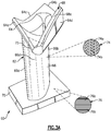
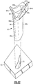
- Figures 3A and 3B illustrate isolated views from different angles of a representative one of the vane arc segments 60
- Figure 3C illustrates an expanded view of the vane arc segment 60.
- the vane arc segments 60 are shown and described with reference to application in the turbine section 28, it is to be understood that the examples herein are also applicable to structural vanes in other sections of the engine 20.
- the vane arc segment 60 is comprised of an airfoil piece 62.
- the airfoil piece 62 defines several sections, including a first platform 64 and an airfoil section 66 that extends radially from the first platform 64.
- the airfoil section 66 is hollow and defines a leading end 66a, a trailing end 66b, and pressure and suction sides 66c/66d.
- the first platform 64 includes forward and aft axial faces 64a/64b and circumferential mate faces 64c/64d.
- the first platform 64 defines a radial flange 68 that extends along at least a portion of the circumferential mate face 64d.
- the radial flange 68 is generally elongated and runs along at least a portion of the extent of the circumferential mate face 64d.
- the radial flange 68 is co-extensive with the mate face 64d, although in modified examples the radial flange 68 may be somewhat shorter than the mate face 64d.
- the radial flange 68 runs along at least 50%, at least 60%, or at least 70% of the extent of the mate face 64d.
- a radial face 68a of the flange 68 may have planar profile or a curved profile.
- the radial face 68a has a curved profile, which may be used to facilitate load transmission.
- the curved profile is that of a cylindrical surface segment.
- a cylindrical surface segment is a surface, here the radial face 68a, that has the shape of a section of a surface of a cylinder.
- the cylindrical surface segment is that of a reference cylinder that has its main axis parallel to the central engine axis A.
- the main axis of the reference cylinder is colinear with the central engine axis A.
- a second platform 70 is carried on the airfoil section 66 radially opposite the first platform 64.
- the second platform 70 includes a through-hole 72 ( Figure 3A ).
- the airfoil section 66 extends through the through-hole 72 ( Figure 3B ) and projects beyond the non-gaspath side of the second platform 70.
- the first platform 64 is a radially outer platform
- the second platform 70 is a radially inner platform. It is to be appreciated that modified examples are also contemplated, in which the platforms 64/70 are switched such that the first platform 64 is a radially inner platform and the second platform 70 is a radially outer platform.
- the illustrated example the vane arc segment 60 is a "singlet" in which the airfoil piece 62 has one airfoil section 66.
- Modified examples are also contemplated in which the vane arc segment is a "multiplet” wherein the airfoil piece 62 has more than one airfoil section 66, such as two or three airfoil sections 66, and the second platform 70 has a corresponding number of through-holes 72.
- the airfoil section 66 is formed of a fiber-reinforced composite (FRC) 74.
- the FRC 74 includes fibers 74a that are disposed in a matrix 74b.
- the FRC 74 also forms the first platform 64 such that fibers 74a are continuous between the airfoil section 66 and the first platform 64, as generally represented at 75.
- the fibers 74a are provided in a fiber structure.
- the fiber structure is, but is not limited to, a braided structure.
- the braided or other fiber structure is tubular so as to define the hollow interior of the airfoil section 66 and flares outwards to form the first platform 64.
- the FRC 74 is either a ceramic matrix composite (CMC) or an organic matrix composite (OMC).
- the matrix 74b is ceramic.
- the ceramic may be, but is not limited to, silicon-containing ceramics.
- the silicon-containing ceramic may be, but is not limited to, silicon carbide (SiC) or silicon nitride (Si 3 N 4 ).
- An example CMC may be a SiC/SiC CMC in which SiC fibers are disposed within a SiC matrix.
- the matrix 74b is an organic polymer, such as but not limited to, polyimide and bismaleimide (BMI).
- An example OMC may be polyimide or BMI matrix with carbon fibers, aramid fibers, ceramic fibers, or glass fibers, as examples.
- the second platform 70 is also formed of a FRC 76 and includes fibers 76a that are disposed in a matrix 76b.
- the fibers 76a are also provided in a fiber structure.
- the fiber structure of the fibers 76a is different than the fiber structure of the fibers 74a.
- the fiber structure of the fibers 76a is stacked fiber plies (laminate). Each fiber ply may have, but is not limited to, a woven or unidirectional fiber configuration.
- the airfoil section 66 has a braided tubular fiber structure and the second platform 70 has a laminate ply structure.
- the FRCs 74/76 may be, but are not limited to, SiC/SiC ceramic matrix composites in which SiC fibers are disposed within a SiC matrix.
- the compositions of the fibers 74a/76a are equivalent and the compositions of the matrices 74b/76b are equivalent.
- the volume percentages of the fibers 74a/76a in their respective FRCs 74/76 may be non-equivalent and selected based on property requirements.
- the fibers 74a of the airfoil piece 62 do not extend into the second platform 70, and the fibers 76a of the second platform 70 do not extend into the airfoil section 66. That is, there are no interconnecting fibers between the airfoil section 66 and the second platform 70.
- Such a configuration facilitates the formation of a tight, consistent braid in the airfoil section 66 since the braid structure is not required to bend/flare outwards to form the second platform 70.
- the tight, consistent braid structure facilitates enhancing strength and durability.
- the second platform 70 may be bonded to the airfoil section 66, or joined with the airfoil section 66 during co-densification to form the matrices 74b/76b.
- the airfoil section 66 and the second platform 70 have been co-densified such that there is a non-fibrous interface 78 of matrix material between the airfoil section 66 and the second platform 70.
- chemical vapor deposition may be utilized to form the matrices 74b/76b.
- the matrix material deposits between the fibers 74a/76a, the matrix material also deposits in the interface between the airfoil section 66 and the second platform 70.
- the matrix material in the interface 78 is non-fibrous.
- the non-fibrous interface 78 is composed of the same composition as the matrices 74b/76b.
- the airfoil section 66 and the second platform 70 are separately fully or partially densified and then the non-fibrous interface 78 is provided in a separate application of a seal or bonding material that joins the airfoil section 66 and the second platform 70.
- the interface 78 need not have structural load-bearing strength as long as the strength is at least sufficient to hold the second platform in place on the airfoil section 66 under the conditions of use in the engine 20.
- the vane arc segment 60 is mounted in the engine 20 between inner and outer support structures 80a/80b, which are schematically represented in Figures 3A and 3B .
- the support structures 80a/80b are not particularly limited and may be annular case structures or the like, and may include intermediate hardware between the case and the vane arc segment 60.
- the support structures 80a/80 are typically formed of, but are not limited to, metallic alloys that can bear the loads received. If in the turbine section 28, combustion gases flow across the airfoil section 66 and gaspath sides of the platforms 64/70. In other sections of the engine 20, the flow may be compressed air or bypass air. The flow causes aerodynamic loads on the vane arc segment 60 that are reacted or transmitted to the support structures 80a/80b.
- vane arc segment 60 is designed to facilitate a low-stress mounting scheme.
- the aerodynamic loads are reacted to the support structures 80a/80b through a load path 82 through the vane arc segment 60.
- the portion of the airfoil section 66 that extends through the second platform 70 (the radially inner end in this example) is mechanically mated to the support structure 80b. Since the fibers 74a/76a do not interconnect the airfoil section 66 and the second platform 70, the second platform 70 is substantially mechanically decoupled from a primary load path 82 through the vane arc segment 60.
- the load path 82 is through the radial extent of the airfoil section 66, into the first platform 64, and through the radial flange 68 into the support structure 80a.
- the second platform 70 is off the load path 82 and is thus non-load-bearing and therefore serves primarily as a gaspath fairing. This non-load bearing configuration, in turn, facilitates the ability of the second platform 70 to handle higher thermal gradients and stresses without impacting structural durability.
- the load path 82 is "corner-to-corner" in the illustrated example, wherein the input load is at the forward pressure side region of the inner end of the airfoil section 66, and the output load is at the aft suction side region of the radial flange 68.
Landscapes
- Engineering & Computer Science (AREA)
- Mechanical Engineering (AREA)
- General Engineering & Computer Science (AREA)
- Chemical & Material Sciences (AREA)
- Materials Engineering (AREA)
- Composite Materials (AREA)
- Structures Of Non-Positive Displacement Pumps (AREA)
- Turbine Rotor Nozzle Sealing (AREA)
Abstract
Description
- A gas turbine engine typically includes a fan section, a compressor section, a combustor section and a turbine section. Air entering the compressor section is compressed and delivered into the combustion section where it is mixed with fuel and ignited to generate a high-speed exhaust gas flow. The high-speed exhaust gas flow expands through the turbine section to drive the compressor and the fan section. The compressor section typically includes low and high pressure compressors, and the turbine section includes low and high pressure turbines.
- Airfoils in the turbine section are typically formed of a superalloy and may include thermal barrier coatings to extend temperature resistance. Ceramics, such as ceramic matrix composite ("CMC") materials, are also being considered for airfoils. CMCs have high temperature resistance. Despite this attribute, there are unique challenges to implementing CMCs in airfoils.
- A vane arc segment according to an example of the present disclosure includes an airfoil piece that defines a first platform and an airfoil section that extends from the first platform. The first platform defines a radial flange that extends along at least a portion of a circumferential mate face of the first platform. The airfoil piece is formed of a fiber-reinforced composite that has fibers that are continuous between the airfoil section and the first platform. A second platform is carried on the airfoil section radially opposite the first platform. The second platform includes a through-hole, and the airfoil section extends through the through-hole.
- In a further embodiment of any of the foregoing embodiments, the fiber-reinforced composite has a braided fiber structure.
- In a further embodiment of any of the foregoing embodiments, the second platform is also formed of a fiber-reinforced composite, and the fiber-reinforced composite of the second platform includes stacked fiber plies.
- In a further embodiment of any of the foregoing embodiments, the airfoil section excludes any fiber plies of the fiber-reinforced composite of the second platform.
- In a further embodiment of any of the foregoing embodiments, the through-hole has a shape that corresponds to the airfoil section.
- In a further embodiment of any of the foregoing embodiments, the fibers of the fiber-reinforced composite of the first platform extend in the radial flange.
- In a further embodiment of any of the foregoing embodiments, the airfoil section is hollow.
- In a further embodiment of any of the foregoing embodiments, there is a non-fibrous interface between the airfoil section and the second platform.
- In a further embodiment of any of the foregoing embodiments, the non-fibrous interface is ceramic.
- A gas turbine engine according to an example of the present disclosure includes a vane arc segment as in any of the foregoing embodiments.
- In a further embodiment of any of the foregoing embodiments, the airfoil piece is formed of a fiber-reinforced composite having fibers that are continuous between the airfoil section and the first platform.
- In a further embodiment of any of the foregoing embodiments, the fiber-reinforced composite has a braided fiber structure.
- In a further embodiment of any of the foregoing embodiments, the second platform is also formed of a fiber-reinforced composite, and the fiber-reinforced composite of the second platform includes stacked fiber plies.
- In a further embodiment of any of the foregoing embodiments, the airfoil section excludes any fiber plies of the fiber-reinforced composite of the second platform.
- In a further embodiment of any of the foregoing embodiments, the fibers of the fiber-reinforced composite of the first platform extend in the radial flange.
- In a further embodiment of any of the foregoing embodiments, there is a non-fibrous interface between the airfoil section and the second platform.
- In a further embodiment of any of the foregoing embodiments, the non-fibrous interface is ceramic.
- The various features and advantages of the present disclosure will become apparent to those skilled in the art from the following detailed description. The drawings that accompany the detailed description can be briefly described as follows.
-
Figure 1 illustrates a gas turbine engine. -
Figure 2 illustrates a vane ring assembly of the engine. -
Figure 3A illustrates an isolated view of a vane arc segment of the vane ring assembly. -
Figure 3B illustrates another view of the vane arc segment ofFigure 3A . -
Figure 3C illustrates an expanded view of the vane arc segment. -
Figure 4 illustrates an interface between a platform and an airfoil section of the vane arc segment. -
Figure 1 schematically illustrates agas turbine engine 20. Thegas turbine engine 20 is disclosed herein as a two-spool turbofan that generally incorporates afan section 22, acompressor section 24, acombustor section 26 and aturbine section 28. Thefan section 22 drives air along a bypass flow path B in a bypass duct defined within ahousing 15 such as a fan case or nacelle, and also drives air along a core flow path C for compression and communication into thecombustor section 26 then expansion through theturbine section 28. Although depicted as a two-spool turbofan gas turbine engine in the disclosed non-limiting embodiment, it should be understood that the concepts described herein are not limited to use with two-spool turbofans as the teachings may be applied to other types of turbine engines including three-spool architectures. - The
exemplary engine 20 generally includes alow speed spool 30 and ahigh speed spool 32 mounted for rotation about an engine central longitudinal axis A relative to an enginestatic structure 36 viaseveral bearing systems 38. It should be understood thatvarious bearing systems 38 at various locations may alternatively or additionally be provided, and the location ofbearing systems 38 may be varied as appropriate to the application. - The
low speed spool 30 generally includes aninner shaft 40 that interconnects, a first (or low)pressure compressor 44 and a first (or low)pressure turbine 46. Theinner shaft 40 is connected to thefan 42 through a speed change mechanism, which in exemplarygas turbine engine 20 is illustrated as a gearedarchitecture 48 to drive afan 42 at a lower speed than thelow speed spool 30. Thehigh speed spool 32 includes anouter shaft 50 that interconnects a second (or high)pressure compressor 52 and a second (or high)pressure turbine 54. Acombustor 56 is arranged inexemplary gas turbine 20 between thehigh pressure compressor 52 and thehigh pressure turbine 54. Amid-turbine frame 57 of the enginestatic structure 36 may be arranged generally between thehigh pressure turbine 54 and thelow pressure turbine 46. Themid-turbine frame 57 further supports bearingsystems 38 in theturbine section 28. Theinner shaft 40 and theouter shaft 50 are concentric and rotate viabearing systems 38 about the engine central longitudinal axis A which is collinear with their longitudinal axes. - The core airflow is compressed by the
low pressure compressor 44 then thehigh pressure compressor 52, mixed and burned with fuel in thecombustor 56, then expanded through thehigh pressure turbine 54 andlow pressure turbine 46. Themid-turbine frame 57 includesairfoils 59 which are in the core airflow path C. Theturbines low speed spool 30 andhigh speed spool 32 in response to the expansion. It will be appreciated that each of the positions of thefan section 22,compressor section 24,combustor section 26,turbine section 28, and fandrive gear system 48 may be varied. For example,gear system 48 may be located aft of the low pressure compressor, or aft of thecombustor section 26 or even aft ofturbine section 28, andfan 42 may be positioned forward or aft of the location ofgear system 48. - The
engine 20 in one example is a high-bypass geared aircraft engine. In a further example, theengine 20 bypass ratio is greater than about six (6), with an example embodiment being greater than about ten (10), the gearedarchitecture 48 is an epicyclic gear train, such as a planetary gear system or other gear system, with a gear reduction ratio of greater than about 2.3 and thelow pressure turbine 46 has a pressure ratio that is greater than about five. In one disclosed embodiment, theengine 20 bypass ratio is greater than about ten (10:1), the fan diameter is significantly larger than that of thelow pressure compressor 44, and thelow pressure turbine 46 has a pressure ratio that is greater than about five 5:1.Low pressure turbine 46 pressure ratio is pressure measured prior to inlet oflow pressure turbine 46 as related to the pressure at the outlet of thelow pressure turbine 46 prior to an exhaust nozzle. The gearedarchitecture 48 may be an epicycle gear train, such as a planetary gear system or other gear system, with a gear reduction ratio of greater than about 2.3:1 and less than about 5:1. It should be understood, however, that the above parameters are only exemplary of one embodiment of a geared architecture engine and that the present invention is applicable to other gas turbine engines including direct drive turbofans. - A significant amount of thrust is provided by the bypass flow B due to the high bypass ratio. The
fan section 22 of theengine 20 is designed for a particular flight condition -- typically cruise at about 0.8 Mach and about 35,000 feet (10,668 meters). The flight condition of 0.8 Mach and 35,000 ft (10,668 meters), with the engine at its best fuel consumption - also known as "bucket cruise Thrust Specific Fuel Consumption ('TSFC')" - is the industry standard parameter of lbm of fuel being burned divided by lbf of thrust the engine produces at that minimum point. "Low fan pressure ratio" is the pressure ratio across the fan blade alone, without a Fan Exit Guide Vane ("FEGV") system. The low fan pressure ratio as disclosed herein according to one non-limiting embodiment is less than about 1.45. "Low corrected fan tip speed" is the actual fan tip speed in ft/sec divided by an industry standard temperature correction of [(Tram °R) / (518.7 °R)]0.5 (where °R = K x 9/5). The "Low corrected fan tip speed" as disclosed herein according to one non-limiting embodiment is less than about 1150 ft / second (350.5 meters/second). -
Figure 2 illustrates a representative portion of a vane ring assembly. The vane ring assembly may be from theturbine section 28 of theengine 20 but is not limited thereto or to hot sections of theengine 20. The vane ring assembly is made up of a plurality ofvane arc segments 60 that are situated in a circumferential row about the engine central axis A.Figures 3A and3B illustrate isolated views from different angles of a representative one of thevane arc segments 60, andFigure 3C illustrates an expanded view of thevane arc segment 60. Although thevane arc segments 60 are shown and described with reference to application in theturbine section 28, it is to be understood that the examples herein are also applicable to structural vanes in other sections of theengine 20. - The
vane arc segment 60 is comprised of anairfoil piece 62. Theairfoil piece 62 defines several sections, including afirst platform 64 and anairfoil section 66 that extends radially from thefirst platform 64. Theairfoil section 66 is hollow and defines aleading end 66a, a trailingend 66b, and pressure andsuction sides 66c/66d. Thefirst platform 64 includes forward and aftaxial faces 64a/64b and circumferential mate faces 64c/64d. - The
first platform 64 defines aradial flange 68 that extends along at least a portion of thecircumferential mate face 64d. Theradial flange 68 is generally elongated and runs along at least a portion of the extent of thecircumferential mate face 64d. In the illustrated example, theradial flange 68 is co-extensive with themate face 64d, although in modified examples theradial flange 68 may be somewhat shorter than themate face 64d. Most typically, theradial flange 68 runs along at least 50%, at least 60%, or at least 70% of the extent of themate face 64d. - A
radial face 68a of theflange 68 may have planar profile or a curved profile. In the illustrated example, theradial face 68a has a curved profile, which may be used to facilitate load transmission. In the illustrated example, the curved profile is that of a cylindrical surface segment. A cylindrical surface segment is a surface, here theradial face 68a, that has the shape of a section of a surface of a cylinder. For example, the cylindrical surface segment is that of a reference cylinder that has its main axis parallel to the central engine axis A. For instance, the main axis of the reference cylinder is colinear with the central engine axis A. - A
second platform 70 is carried on theairfoil section 66 radially opposite thefirst platform 64. Thesecond platform 70 includes a through-hole 72 (Figure 3A ). Theairfoil section 66 extends through the through-hole 72 (Figure 3B ) and projects beyond the non-gaspath side of thesecond platform 70. In the illustrated example, thefirst platform 64 is a radially outer platform, and thesecond platform 70 is a radially inner platform. It is to be appreciated that modified examples are also contemplated, in which theplatforms 64/70 are switched such that thefirst platform 64 is a radially inner platform and thesecond platform 70 is a radially outer platform. Additionally, the illustrated example thevane arc segment 60 is a "singlet" in which theairfoil piece 62 has oneairfoil section 66. Modified examples are also contemplated in which the vane arc segment is a "multiplet" wherein theairfoil piece 62 has more than oneairfoil section 66, such as two or threeairfoil sections 66, and thesecond platform 70 has a corresponding number of through-holes 72. - As shown by inset in
Figure 3A , theairfoil section 66 is formed of a fiber-reinforced composite (FRC) 74. TheFRC 74 includesfibers 74a that are disposed in amatrix 74b. TheFRC 74 also forms thefirst platform 64 such thatfibers 74a are continuous between theairfoil section 66 and thefirst platform 64, as generally represented at 75. Thefibers 74a are provided in a fiber structure. As shown in this example, the fiber structure is, but is not limited to, a braided structure. The braided or other fiber structure is tubular so as to define the hollow interior of theairfoil section 66 and flares outwards to form thefirst platform 64. - The
FRC 74 is either a ceramic matrix composite (CMC) or an organic matrix composite (OMC). For the CMC, thematrix 74b is ceramic. The ceramic may be, but is not limited to, silicon-containing ceramics. The silicon-containing ceramic may be, but is not limited to, silicon carbide (SiC) or silicon nitride (Si3N4). An example CMC may be a SiC/SiC CMC in which SiC fibers are disposed within a SiC matrix. For the OMC, thematrix 74b is an organic polymer, such as but not limited to, polyimide and bismaleimide (BMI). An example OMC may be polyimide or BMI matrix with carbon fibers, aramid fibers, ceramic fibers, or glass fibers, as examples. - The
second platform 70 is also formed of aFRC 76 and includes fibers 76a that are disposed in amatrix 76b. The fibers 76a are also provided in a fiber structure. The fiber structure of the fibers 76a is different than the fiber structure of thefibers 74a. In the illustrated example, the fiber structure of the fibers 76a is stacked fiber plies (laminate). Each fiber ply may have, but is not limited to, a woven or unidirectional fiber configuration. In general, theairfoil section 66 has a braided tubular fiber structure and thesecond platform 70 has a laminate ply structure. TheFRCs 74/76 may be, but are not limited to, SiC/SiC ceramic matrix composites in which SiC fibers are disposed within a SiC matrix. In that regard, in some examples, the compositions of thefibers 74a/76a are equivalent and the compositions of thematrices 74b/76b are equivalent. The volume percentages of thefibers 74a/76a in theirrespective FRCs 74/76 may be non-equivalent and selected based on property requirements. - As the
airfoil piece 62 and thesecond platform 70 are distinct pieces, thefibers 74a of theairfoil piece 62 do not extend into thesecond platform 70, and the fibers 76a of thesecond platform 70 do not extend into theairfoil section 66. That is, there are no interconnecting fibers between theairfoil section 66 and thesecond platform 70. Such a configuration facilitates the formation of a tight, consistent braid in theairfoil section 66 since the braid structure is not required to bend/flare outwards to form thesecond platform 70. The tight, consistent braid structure facilitates enhancing strength and durability. - The
second platform 70 may be bonded to theairfoil section 66, or joined with theairfoil section 66 during co-densification to form thematrices 74b/76b. For instance, as shown in a representative view inFigure 4 , theairfoil section 66 and thesecond platform 70 have been co-densified such that there is anon-fibrous interface 78 of matrix material between theairfoil section 66 and thesecond platform 70. As an example, chemical vapor deposition may be utilized to form thematrices 74b/76b. As the matrix material deposits between thefibers 74a/76a, the matrix material also deposits in the interface between theairfoil section 66 and thesecond platform 70. As there are no fibers in the interface from either theairfoil section 66 or thesecond platform 70, the matrix material in theinterface 78 is non-fibrous. In this regard, thenon-fibrous interface 78 is composed of the same composition as thematrices 74b/76b. Alternatively, rather than forming thenon-fibrous interface 78 during co-densification, theairfoil section 66 and thesecond platform 70 are separately fully or partially densified and then thenon-fibrous interface 78 is provided in a separate application of a seal or bonding material that joins theairfoil section 66 and thesecond platform 70. Since the load path through the vane arc segment 60 (discussed below) is not through thesecond platform 70, theinterface 78 need not have structural load-bearing strength as long as the strength is at least sufficient to hold the second platform in place on theairfoil section 66 under the conditions of use in theengine 20. - The
vane arc segment 60 is mounted in theengine 20 between inner andouter support structures 80a/80b, which are schematically represented inFigures 3A and3B . Thesupport structures 80a/80b are not particularly limited and may be annular case structures or the like, and may include intermediate hardware between the case and the vane arc segment 60., Thesupport structures 80a/80 are typically formed of, but are not limited to, metallic alloys that can bear the loads received. If in theturbine section 28, combustion gases flow across theairfoil section 66 and gaspath sides of theplatforms 64/70. In other sections of theengine 20, the flow may be compressed air or bypass air. The flow causes aerodynamic loads on thevane arc segment 60 that are reacted or transmitted to thesupport structures 80a/80b. - In general, support schemes for mounting structural vane segments formed of fiber-reinforced composites are challenging due to lower material stress limits. For ceramic matrix composites the stress limits are lower in comparison to high strength superalloys used for some traditional vane segments. For instance, traditional support schemes that utilize hooks or a series of rails can concentrate stresses, create aerodynamic loads, and/or create thermal stresses which may exceed material limits of FRCs, and ceramic matrix composite in particular. Moreover, traditional hooks and rails often have complex geometries that are challenging to manufacture from FRCs. Therefore, even though FRCs may have many potential benefits, such benefits cannot be realized without a suitable support scheme. In this regard, as discussed below, the
vane arc segment 60 is designed to facilitate a low-stress mounting scheme. - The aerodynamic loads, represented by aerodynamic forces Rz, Rx, and Ry in
Figure 3B , are reacted to thesupport structures 80a/80b through aload path 82 through thevane arc segment 60. In this example, the portion of theairfoil section 66 that extends through the second platform 70 (the radially inner end in this example) is mechanically mated to thesupport structure 80b. Since thefibers 74a/76a do not interconnect theairfoil section 66 and thesecond platform 70, thesecond platform 70 is substantially mechanically decoupled from aprimary load path 82 through thevane arc segment 60. Theload path 82 is through the radial extent of theairfoil section 66, into thefirst platform 64, and through theradial flange 68 into thesupport structure 80a. Thesecond platform 70 is off theload path 82 and is thus non-load-bearing and therefore serves primarily as a gaspath fairing. This non-load bearing configuration, in turn, facilitates the ability of thesecond platform 70 to handle higher thermal gradients and stresses without impacting structural durability. In general, theload path 82 is "corner-to-corner" in the illustrated example, wherein the input load is at the forward pressure side region of the inner end of theairfoil section 66, and the output load is at the aft suction side region of theradial flange 68. - Although a combination of features is shown in the illustrated examples, not all of them need to be combined to realize the benefits of various embodiments of this disclosure. In other words, a system designed according to an embodiment of this disclosure will not necessarily include all of the features shown in any one of the Figures or all of the portions schematically shown in the Figures. Moreover, selected features of one example embodiment may be combined with selected features of other example embodiments.
- The preceding description is exemplary rather than limiting in nature. Variations and modifications to the disclosed examples may become apparent to those skilled in the art that do not necessarily depart from this disclosure. The scope of legal protection given to this disclosure can only be determined by studying the following claims.
Claims (15)
- A vane arc segment (60) comprising:an airfoil piece (62) defining a first platform (64) and an airfoil section (66) extending from the first platform (64), the first platform (64) defining a radial flange (68) extending along at least a portion of a circumferential mate face (64d) of the first platform (64), the airfoil piece (62) being formed of a fiber-reinforced composite having fibers (74a) that are continuous between the airfoil section (66) and the first platform (64); anda second platform (70) carried on the airfoil section (66) radially opposite the first platform (64), the second platform (70) including a through-hole (72), the airfoil section (66) extending through the through-hole (72).
- The vane arc segment (60) as recited in claim 1, wherein the fiber-reinforced composite has a braided fiber structure.
- The vane arc segment (60) as recited in claim 1 or 2, wherein the second platform (70) is also formed of a fiber-reinforced composite, and the fiber-reinforced composite of the second platform (70) includes stacked fiber plies.
- The vane arc segment (60) as recited in claim 3, wherein the airfoil section (66) excludes any fiber plies of the fiber-reinforced composite of the second platform (70).
- The vane arc segment (60) as recited in any preceding claim, wherein the through-hole (72) has a shape that corresponds to the airfoil section (66).
- The vane arc segment (60) as recited in any preceding claim, wherein the fibers (74a) of the fiber-reinforced composite of the first platform (64) extend in the radial flange (68).
- The vane arc segment (60) as recited in any preceding claim, wherein the airfoil section (66) is hollow.
- The vane arc segment (60) as recited in any preceding claim, wherein there is a non-fibrous interface (78) between the airfoil section (66) and the second platform (70).
- The vane arc segment (60) as recited in claim 8, wherein the non-fibrous interface (78) is ceramic.
- A gas turbine engine (20) comprising:first and second support structures (80a, 80b);vane arc segments (60) supported between the first and second support structures (80a, 80b), each said vane arc segment (60) includingan airfoil piece (62) defining a first platform (64) and an airfoil section (66) extending from the first platform (64), the first platform (64) defining a radial flange (68) extending along at least a portion of a circumferential mate face (64d) of the first platform (64), anda second platform (70) carried on the airfoil section (66) radially opposite the first platform (64), the second platform (70) including a through-hole (72), the airfoil section (66) extending through the through-hole (72), anda load path (82) from the first support structure (80a) extending through the airfoil section (66), the first platform (64), and the radial flange (68) to the second support structure (80b), the second platform (70) being non-load bearing with regard to the load path (82).
- The engine (20) as recited in claim 10, wherein the airfoil piece (62) is formed of a fiber-reinforced composite having fibers (74a) that are continuous between the airfoil section (66) and the first platform (64).
- The engine (20) as recited in claim 11, wherein the fiber-reinforced composite has a braided fiber structure.
- The engine (20) as recited in claim 11 or 12, wherein the second platform (70) is also formed of a fiber-reinforced composite, and the fiber-reinforced composite of the second platform (70) includes stacked fiber plies, optionally wherein the airfoil section (66) excludes any fiber plies of the fiber-reinforced composite of the second platform (70).
- The engine (20) as recited in claim 11, 12 or 13, wherein the fibers (74a) of the fiber-reinforced composite of the first platform (64) extend in the radial flange (68).
- The engine (20) as recited in any of claims 10 to 14, wherein there is a non-fibrous interface (78) between the airfoil section (66) and the second platform (70), optionally wherein the non-fibrous interface (78) is ceramic.
Applications Claiming Priority (1)
| Application Number | Priority Date | Filing Date | Title |
|---|---|---|---|
| US16/783,300 US11333037B2 (en) | 2020-02-06 | 2020-02-06 | Vane arc segment load path |
Publications (1)
| Publication Number | Publication Date |
|---|---|
| EP3862538A1 true EP3862538A1 (en) | 2021-08-11 |
Family
ID=74561804
Family Applications (1)
| Application Number | Title | Priority Date | Filing Date |
|---|---|---|---|
| EP21155817.6A Pending EP3862538A1 (en) | 2020-02-06 | 2021-02-08 | Vane arc segment load path |
Country Status (2)
| Country | Link |
|---|---|
| US (1) | US11333037B2 (en) |
| EP (1) | EP3862538A1 (en) |
Families Citing this family (4)
| Publication number | Priority date | Publication date | Assignee | Title |
|---|---|---|---|---|
| US11591920B2 (en) * | 2020-11-13 | 2023-02-28 | Raytheon Technologies Corporation | Vane arc segment with curved radial flange |
| FR3118096B1 (en) * | 2020-12-18 | 2023-11-17 | Safran Aircraft Engines | BLADE MADE OF COMPOSITE MATRIX WITH AT LEAST PARTIALLY CERAMIC MATRIX |
| US12071864B2 (en) | 2022-01-21 | 2024-08-27 | Rtx Corporation | Turbine section with ceramic support rings and ceramic vane arc segments |
| US11708765B1 (en) * | 2022-05-13 | 2023-07-25 | Raytheon Technologies Corporation | Gas turbine engine article with branched flange |
Citations (6)
| Publication number | Priority date | Publication date | Assignee | Title |
|---|---|---|---|---|
| EP1239119A1 (en) * | 2001-03-07 | 2002-09-11 | General Electric Company | Turbine vane assembly including a low ductility vane |
| US7147434B2 (en) * | 2003-06-30 | 2006-12-12 | Snecma Moteurs | Nozzle ring with adhesive bonded blading for aircraft engine compressor |
| EP2371521A1 (en) * | 2010-04-02 | 2011-10-05 | Techspace Aero S.A. | Method of manufacturing a rectifier |
| EP3075963A1 (en) * | 2015-03-30 | 2016-10-05 | General Electric Company | Hybrid nozzle segment assemblies for a gas turbine engine |
| EP3121379A1 (en) * | 2015-07-24 | 2017-01-25 | General Electric Company | Ceramic matrix composite airfoil assembly |
| US20180347383A1 (en) * | 2017-05-30 | 2018-12-06 | Rolls-Royce Corporation | Turbine vane assembly with ceramic matrix composite airfoil and friction fit metallic attachment features |
Family Cites Families (25)
| Publication number | Priority date | Publication date | Assignee | Title |
|---|---|---|---|---|
| US5332360A (en) * | 1993-09-08 | 1994-07-26 | General Electric Company | Stator vane having reinforced braze joint |
| US6197424B1 (en) * | 1998-03-27 | 2001-03-06 | Siemens Westinghouse Power Corporation | Use of high temperature insulation for ceramic matrix composites in gas turbines |
| FR2817192B1 (en) * | 2000-11-28 | 2003-08-08 | Snecma Moteurs | ASSEMBLY FORMED BY AT LEAST ONE BLADE AND A BLADE ATTACHMENT PLATFORM FOR A TURBOMACHINE, AND METHOD FOR THE PRODUCTION THEREOF |
| US6821087B2 (en) * | 2002-01-21 | 2004-11-23 | Honda Giken Kogyo Kabushiki Kaisha | Flow-rectifying member and its unit and method for producing flow-rectifying member |
| US6648597B1 (en) | 2002-05-31 | 2003-11-18 | Siemens Westinghouse Power Corporation | Ceramic matrix composite turbine vane |
| US7510379B2 (en) * | 2005-12-22 | 2009-03-31 | General Electric Company | Composite blading member and method for making |
| US20090074576A1 (en) | 2006-04-20 | 2009-03-19 | Florida Turbine Technologies, Inc. | Turbine blade with cooling breakout passages |
| JP5311126B2 (en) | 2009-03-26 | 2013-10-09 | 株式会社Ihi | CMC turbine stationary blade |
| FR2943942B1 (en) * | 2009-04-06 | 2016-01-29 | Snecma | PROCESS FOR MANUFACTURING A TURBOMACHINE BLADE OF COMPOSITE MATERIAL |
| FR2946999B1 (en) * | 2009-06-18 | 2019-08-09 | Safran Aircraft Engines | CMC TURBINE DISPENSER ELEMENT, PROCESS FOR MANUFACTURING SAME, AND DISPENSER AND GAS TURBINE INCORPORATING SAME. |
| US8206096B2 (en) * | 2009-07-08 | 2012-06-26 | General Electric Company | Composite turbine nozzle |
| FR2953885B1 (en) * | 2009-12-14 | 2012-02-10 | Snecma | TURBOMACHINE DRAFT IN COMPOSITE MATERIAL AND METHOD FOR MANUFACTURING THE SAME |
| EP2354453B1 (en) | 2010-02-02 | 2018-03-28 | Siemens Aktiengesellschaft | Turbine engine component for adaptive cooling |
| FR2983519B1 (en) | 2011-12-01 | 2015-07-24 | Snecma Propulsion Solide | TURBINE DRAWER WITH HOLLOW BLADE OF COMPOSITE MATERIAL, TURBINE OR COMPRESSOR HAVING A DISPENSER OR RECTIFIER FORMED SUCH AS AUBES AND TURBOMACHINE COMPRISING THEM |
| FR2983428B1 (en) * | 2011-12-01 | 2014-01-17 | Snecma Propulsion Solide | PROCESS FOR MANUFACTURING A TURBOMACHINE BLADE IN COMPOSITE MATERIAL WITH INTEGRATED PLATFORMS |
| US9308708B2 (en) * | 2012-03-23 | 2016-04-12 | General Electric Company | Process for producing ceramic composite components |
| CA2899891A1 (en) * | 2013-03-14 | 2014-10-02 | Adam L. CHAMBERLAIN | Bi-cast turbine vane |
| EP3482846B1 (en) * | 2013-11-18 | 2021-07-14 | Raytheon Technologies Corporation | Coated casting cores and manufacture methods |
| US9718735B2 (en) | 2015-02-03 | 2017-08-01 | General Electric Company | CMC turbine components and methods of forming CMC turbine components |
| US10408084B2 (en) | 2015-03-02 | 2019-09-10 | Rolls-Royce North American Technologies Inc. | Vane assembly for a gas turbine engine |
| GB201513236D0 (en) * | 2015-07-28 | 2015-09-09 | Rolls Royce Plc | A nozzle guide vane passage |
| US11466580B2 (en) * | 2018-05-02 | 2022-10-11 | General Electric Company | CMC nozzle with interlocking mechanical joint and fabrication |
| US11041394B2 (en) | 2018-06-01 | 2021-06-22 | Rolls-Royce Corporation | CMC airfoil joint |
| US10934870B2 (en) * | 2018-09-17 | 2021-03-02 | Rolls Royce Plc | Turbine vane assembly with reinforced end wall joints |
| US11162377B2 (en) * | 2019-05-31 | 2021-11-02 | Rolls-Royce High Temperature Composites Inc. | Ceramic matrix composite turbine vane and method for making |
-
2020
- 2020-02-06 US US16/783,300 patent/US11333037B2/en active Active
-
2021
- 2021-02-08 EP EP21155817.6A patent/EP3862538A1/en active Pending
Patent Citations (6)
| Publication number | Priority date | Publication date | Assignee | Title |
|---|---|---|---|---|
| EP1239119A1 (en) * | 2001-03-07 | 2002-09-11 | General Electric Company | Turbine vane assembly including a low ductility vane |
| US7147434B2 (en) * | 2003-06-30 | 2006-12-12 | Snecma Moteurs | Nozzle ring with adhesive bonded blading for aircraft engine compressor |
| EP2371521A1 (en) * | 2010-04-02 | 2011-10-05 | Techspace Aero S.A. | Method of manufacturing a rectifier |
| EP3075963A1 (en) * | 2015-03-30 | 2016-10-05 | General Electric Company | Hybrid nozzle segment assemblies for a gas turbine engine |
| EP3121379A1 (en) * | 2015-07-24 | 2017-01-25 | General Electric Company | Ceramic matrix composite airfoil assembly |
| US20180347383A1 (en) * | 2017-05-30 | 2018-12-06 | Rolls-Royce Corporation | Turbine vane assembly with ceramic matrix composite airfoil and friction fit metallic attachment features |
Also Published As
| Publication number | Publication date |
|---|---|
| US20210246808A1 (en) | 2021-08-12 |
| US11333037B2 (en) | 2022-05-17 |
Similar Documents
| Publication | Publication Date | Title |
|---|---|---|
| EP3862538A1 (en) | Vane arc segment load path | |
| EP3800327B1 (en) | Axially sloped vane mate face flange | |
| EP4006307A2 (en) | Vane arc segment with curved radial flange | |
| EP4001592A1 (en) | Cmc vane arc segment with cantilevered spar | |
| EP3971391A2 (en) | Cmc vane for a gas turbine engine with support and impingement baffle | |
| EP4180633B1 (en) | Airfoil of a gas turbine made of fiber plies having interdigitated fingers in trailing end | |
| US12025020B2 (en) | Vane system with continuous support ring | |
| EP4030036A1 (en) | Vane arc segment support platform with curved radial channel | |
| EP3825519A1 (en) | Vane with collar | |
| EP3865669B1 (en) | Vane arc segment platform flange for a gas turbine engine with cap | |
| US12305530B2 (en) | Airfoil with venturi tube | |
| EP4215722A1 (en) | Turbine section with ceramic support rings and ceramic vane arc segments | |
| EP4520920A1 (en) | Tilted cmc vane arc segment | |
| EP4067620A1 (en) | Airfoil with radially-spaced ribs and interlocking tabs, and gas turbine engine | |
| US12000306B2 (en) | Vane arc segment with single-sided platforms | |
| US11668199B2 (en) | Vane arc segment with radially projecting flanges | |
| US12416242B2 (en) | Blade outer air seal with compliant seal |
Legal Events
| Date | Code | Title | Description |
|---|---|---|---|
| PUAI | Public reference made under article 153(3) epc to a published international application that has entered the european phase |
Free format text: ORIGINAL CODE: 0009012 |
|
| STAA | Information on the status of an ep patent application or granted ep patent |
Free format text: STATUS: THE APPLICATION HAS BEEN PUBLISHED |
|
| AK | Designated contracting states |
Kind code of ref document: A1 Designated state(s): AL AT BE BG CH CY CZ DE DK EE ES FI FR GB GR HR HU IE IS IT LI LT LU LV MC MK MT NL NO PL PT RO RS SE SI SK SM TR |
|
| STAA | Information on the status of an ep patent application or granted ep patent |
Free format text: STATUS: REQUEST FOR EXAMINATION WAS MADE |
|
| 17P | Request for examination filed |
Effective date: 20220211 |
|
| RBV | Designated contracting states (corrected) |
Designated state(s): AL AT BE BG CH CY CZ DE DK EE ES FI FR GB GR HR HU IE IS IT LI LT LU LV MC MK MT NL NO PL PT RO RS SE SI SK SM TR |
|
| STAA | Information on the status of an ep patent application or granted ep patent |
Free format text: STATUS: EXAMINATION IS IN PROGRESS |
|
| 17Q | First examination report despatched |
Effective date: 20230802 |
|
| RAP3 | Party data changed (applicant data changed or rights of an application transferred) |
Owner name: RTX CORPORATION |