EP3862513A1 - Binding machine - Google Patents
Binding machine Download PDFInfo
- Publication number
- EP3862513A1 EP3862513A1 EP21156049.5A EP21156049A EP3862513A1 EP 3862513 A1 EP3862513 A1 EP 3862513A1 EP 21156049 A EP21156049 A EP 21156049A EP 3862513 A1 EP3862513 A1 EP 3862513A1
- Authority
- EP
- European Patent Office
- Prior art keywords
- wire
- unit
- feeding
- main body
- binding machine
- Prior art date
- Legal status (The legal status is an assumption and is not a legal conclusion. Google has not performed a legal analysis and makes no representation as to the accuracy of the status listed.)
- Granted
Links
Images




Classifications
-
- B—PERFORMING OPERATIONS; TRANSPORTING
- B65—CONVEYING; PACKING; STORING; HANDLING THIN OR FILAMENTARY MATERIAL
- B65B—MACHINES, APPARATUS OR DEVICES FOR, OR METHODS OF, PACKAGING ARTICLES OR MATERIALS; UNPACKING
- B65B13/00—Bundling articles
- B65B13/02—Applying and securing binding material around articles or groups of articles, e.g. using strings, wires, strips, bands or tapes
- B65B13/025—Hand-held tools
-
- B—PERFORMING OPERATIONS; TRANSPORTING
- B65—CONVEYING; PACKING; STORING; HANDLING THIN OR FILAMENTARY MATERIAL
- B65B—MACHINES, APPARATUS OR DEVICES FOR, OR METHODS OF, PACKAGING ARTICLES OR MATERIALS; UNPACKING
- B65B13/00—Bundling articles
- B65B13/18—Details of, or auxiliary devices used in, bundling machines or bundling tools
-
- B—PERFORMING OPERATIONS; TRANSPORTING
- B65—CONVEYING; PACKING; STORING; HANDLING THIN OR FILAMENTARY MATERIAL
- B65B—MACHINES, APPARATUS OR DEVICES FOR, OR METHODS OF, PACKAGING ARTICLES OR MATERIALS; UNPACKING
- B65B13/00—Bundling articles
- B65B13/02—Applying and securing binding material around articles or groups of articles, e.g. using strings, wires, strips, bands or tapes
- B65B13/04—Applying and securing binding material around articles or groups of articles, e.g. using strings, wires, strips, bands or tapes with means for guiding the binding material around the articles prior to severing from supply
-
- B—PERFORMING OPERATIONS; TRANSPORTING
- B65—CONVEYING; PACKING; STORING; HANDLING THIN OR FILAMENTARY MATERIAL
- B65B—MACHINES, APPARATUS OR DEVICES FOR, OR METHODS OF, PACKAGING ARTICLES OR MATERIALS; UNPACKING
- B65B27/00—Bundling particular articles presenting special problems using string, wire, or narrow tape or band; Baling fibrous material, e.g. peat, not otherwise provided for
- B65B27/10—Bundling rods, sticks, or like elongated objects
-
- E—FIXED CONSTRUCTIONS
- E04—BUILDING
- E04G—SCAFFOLDING; FORMS; SHUTTERING; BUILDING IMPLEMENTS OR AIDS, OR THEIR USE; HANDLING BUILDING MATERIALS ON THE SITE; REPAIRING, BREAKING-UP OR OTHER WORK ON EXISTING BUILDINGS
- E04G21/00—Preparing, conveying, or working-up building materials or building elements in situ; Other devices or measures for constructional work
- E04G21/12—Mounting of reinforcing inserts; Prestressing
- E04G21/122—Machines for joining reinforcing bars
- E04G21/123—Wire twisting tools
Definitions
- the present disclosure relates to a binding machine.
- to-be-bound objects such as reinforcing bars are generally used so as to reinforce strength of a tensile force.
- the to-be-bound objects are bound with wires so that the reinforcing bars do not deviate from predetermined positions. In this case, if the binding by the wire is loosened, positions of the to-be-bound objects deviate, so that appropriate strength by the to-be-bound objects is not obtained. For this reason, it is required to firmly bind the to-be-bound objects by the wires.
- PTL 1 discloses a reinforcing bar binding machine configured to feed a wire in a loop shape and to wind the wire around reinforcing bars, to pull back the wire with maintaining a tip end of the wire and to wind the wire on the reinforcing bars, and to twist the wire, thereby binding the reinforcing bars with the wire.
- a wire reel is arranged on a front side of the main body. Therefore, when binding the to-be-bound objects for a complex building, the to-be-bound objects cannot be inserted into the reinforcing bar binding machine because a reel accommodation unit is provided on the front side of the main body, so that the to-be-bound objects cannot be bound.
- the reel accommodation unit is arranged on a rear side of the main body. However, when feeding the wire, a wire feeding defect may occur or a feeding path in the binding machine is worn due to friction with the wire.
- a binding machine configured to feed a wire in a first direction, to curl the wire, to surround a to-be-bound object with the wire, to return the wire in a second direction opposite to the first direction, to wind the wire on the to-be-bound object, and to twist the wire, thereby binding the to-be-bound object
- the binding machine comprising: a main body; a reel accommodation unit configured to rotatably accommodate a reel on which the wire is wound; a wire feeding unit provided in the main body and configured to feed the wire in the first direction and in the second direction; a curl forming unit provided on a tip end-side of the main body and configured to curl the wire fed by the wire feeding unit; a binding unit comprising a twisting shaft extending from the tip end-side to a rear end-side of the main body, and configured to twist the wire curled by the curl forming unit by rotation of the twisting shaft; a grip extending from a circumferential surface of the main body; a starter
- the reel accommodation unit is provided in the main body at the rear of the starter, it is possible to bind the to-be-bound object even though it is complex.
- the feeding path is provided with the load reducing part, it is possible to reduce the load to the wire or the reel accommodation unit when feeding or returning the wire.
- FIG. 1 is a side view of a reinforcing bar binding machine 1A of the present embodiment
- FIG. 2 is a perspective view of the reinforcing bar binding machine 1A
- FIG. 3 is a side view depicting a state where a cover body 22 of a reel accommodation unit 2 of the reinforcing bar binding machine 1A is opened
- FIG. 4 is a perspective view depicting the state where the cover body 22 of the reel accommodation unit 2 of the reinforcing bar binding machine 1A is opened
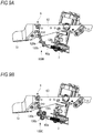
- FIG. 5A is a side view depicting an internal configuration of the reinforcing bar binding machine 1A
- FIG. 5B is a sectional view depicting the internal configuration of the reinforcing bar binding machine 1A
- FIG. 6A depicts the cover body 22 of the reel accommodation unit 2
- FIG. 6B depicts a modified embodiment of the reel accommodation unit 2.
- a longitudinal direction of the main body 10 (a direction corresponding to the right and left direction in FIG. 1 ) is referred to as the front and rear direction
- a side on which a curl forming unit 5 is provided is referred to as a front side or a tip end-side of the reinforcing bar binding machine 1A
- a side on which a reel accommodation unit 2 is provided is referred to as a rear side of the reinforcing bar binding machine 1A
- a side on which a battery 15 is provided and which is a direction orthogonal to the front and rear direction is referred to as a lower side of the reinforcing bar binding machine 1A, and an opposite side thereto is referred to as an upper side of the reinforcing bar binding machine 1A.
- a side (an inner side of the drawing sheet of FIG. 1 ) on which a twisting motor 80 is provided and which is orthogonal to the front and rear direction and the upper and lower direction of the reinforcing bar binding machine 1A is referred to as a right side of the reinforcing bar binding machine 1A
- a side (a front side of the drawing sheet of FIG. 1 ) on which the reel accommodation unit 2 is provided is referred to as a left side of the reinforcing bar binding machine 1A.
- a direction in which a feeding motor 30 is rotated forward to feed a wire W from a wire feeding unit 3-side toward a curl forming unit 5-side is referred to as a forward direction (first direction)
- a direction in which the feeding motor 30 is reversely rotated to feed the wire W from the curl forming unit 5-side toward the wire feeding unit 3-side is referred to as a reverse direction (second direction).
- the reinforcing bar binding machine 1A includes a main body 10 having an elongated cuboid shape, a reel accommodation unit 2 in which a wire W is accommodated, a wire feeding unit 3 configured to feed the wire W in the forward direction and in the reverse direction, and a curl forming unit 5 configured to wind the wire W fed by the wire feeding unit 3 around reinforcing bars S.
- the reinforcing bar binding machine 1A also includes a cutting unit 6 configured to cut the wire wound on the reinforcing bars S by the wire feeding unit 3, a binding unit 7 configured to twist the wire W wound on the reinforcing bars S, and a drive unit 8 configured to drive the binding unit 7.
- the wire W is fed in the forward direction and wound around the reinforcing bars S, which are a to-be-bound object, the wire W wound around the reinforcing bars S is fed in the reverse direction and is then wound on the reinforcing bars S, and the wire W is then twisted, so that the reinforcing bars S can be bound with the wire W.
- the main body 10 is provided therein with a feeding path 90 for feeding the wire W in the forward direction or in the reverse direction.
- the feeding path 90 is formed with extending between the reel accommodation unit 2 and the curl forming unit 5 in the main body 10, below a twisting shaft 72 extending between the tip end-side and the rear end-side of the main body 10, more specifically, on a lower side in the main body 10.
- a reel 26 on which the wire W is wound to be reeled out is rotatably accommodated and is also accommodated to be detachable and replaceable with respect to the main body 10.
- the reel accommodation unit 2 is arranged at a rear part of the main body 10 at the rear of a trigger 12.
- the reel accommodation unit 2 is arranged at a position offset in a left direction orthogonal to an axis direction of the twisting shaft 72, with respect to the wire feeding unit 3,
- the reel accommodation unit 2 has a concave part 20 formed on a left sidewall 10a of the main body 10, and a cover body 22 for opening/closing the concave part 20.
- the concave part 20 has a size capable of accommodating a flange part 26b (refer to FIG. 6A ) on one side of the reel 26 having a substantially circular cylinder shape, and has a reel support part 21 configured to rotatably support the reel 26.
- the cover body 22 has a peripheral wall 22a having a cylindrical shape, an end wall 22b for covering one opening of the peripheral wall 22a, an entry 22c for the wire W formed at a part of the peripheral wall 22a, and a path cover 22d configured to communicate with the entry 22c and to cover a part (a second path 90b to be described later) of the feeding path 90.
- An upper end portion of the peripheral wall 22a is provided with a rotation portion 22e for rotatably attaching the cover body 22 to the main body 10.
- the rotation portion 22e of the cover body 22 is attached to an attachment portion 10e (refer to FIG. 2 ) formed at the main body 10, so that the cover body 22 can rotate about the rotation portion 22e as a support point.
- the reel 26 can be set in the concave part 20 and the reel 26 set in the concave part 20 can be taken out.
- the cover body 22 is closed, the cover body 22 is locked to the main body 10 by a lock mechanism (not shown).
- a rotary shaft of the rotation portion 22e of the cover body 22 is arranged in the longitudinal direction of the main body 10, as shown in FIG. 2 and the like.
- the rotary shaft of the rotation portion 22e may be arranged in a width direction (right and left direction) of the main body 10 so that the reel 26 can be set from the rear of the main body 10, and the cover body 22 may be configured to be opened and closed with respect to the rear of the main body 10.
- the attachment portion 10e is provided at a rear end portion of a lower surface-side of the main body 10, and the cover body 22 is configured to be rotatable about the rotary shaft (support point) of the rotation portion 22e of the cover body 22.
- an upper end portion of the cover body 22 may be provided with a lock mechanism 23 so that the cover body 22 can be locked to the main body 10.
- the rotation portion 22e and the attachment portion 10e may be provided on an upper side of the main body opposite to FIG. 6B .
- the reel accommodation unit 2 may be arranged at a position further offset rearward than the twisting motor 80 in a state where the rotation portion 22e is provided in the longitudinal direction as shown in FIG. 1 . In this case, the reel accommodation unit 2 may be arranged offset or without being offset with respect to the twisting motor 80.
- the reel 26 has a cylindrical hub part 26a on which the wire W is to be wound, and a pair of flange parts 26b and 26b provided integrally on both axial ends of the hub part 26a.
- One or more wires W are wound on the hub part 26a of the reel 26, and the wire W can be pulled out from the reel 26.
- a wire made of a plastically deformable metal wire, a wire having a metal wire covered with a resin, a twisted wire and the like are used for the wire W.
- a grip 11 extends substantially downward from a lower surface that is a substantially intermediate part of the main body 10 in the longitudinal direction and a part of a circumferential surface of the main body 10.
- the grip 11 is provided below the twisting shaft 72 extending in the front and rear direction of the main body 10.
- An upper end portion of the grip 11 is provided on its front surface with a trigger 12 that is an example of the starter.
- a battery 15 that configures a power supply unit is detachably attached to a lower part of the grip 11.
- the wire feeding unit 3 includes a pair of first and second feeding gears, and is configured to feed the wire W with sandwiching the wire W between grooves formed on gear teeth of the first feeding gear and grooves formed on gear teeth of the second feeding gear.
- the first feeding gear of the wire feeding unit 3 is connected, for example, to a feeding motor 30, so that it is rotated by drive of the feeding motor 30.
- the second feeding gear of the wire feeding unit 3 is driven to rotate in connection with rotation of the first feeding gear.
- the wire feeding unit 3 feeds the wire W in the forward direction, and in a case where the rotation direction of the feeding motor 30 is switched to a reverse rotation direction, the wire feeding unit 3 feeds the wire W in a reverse direction.
- the curl forming unit 5 is provided on the tip end-side of the main body 10 and above the twisting shaft 72.
- the curl forming unit 5 includes a curl guide 50 configured to curl the wire W that is fed by the wire feeding unit 3, and an induction guide 51 configured to guide the wire W curled by the curl guide 50 toward the binding unit 7.
- the curl guide 50 has a guide groove 52 configuring a feeding path of the wire W, and a first guide pin 53a and a second guide pin 53b configured to curl the wire W in cooperation with the guide groove 52.
- the first guide pin 53a is arranged on an upstream side of the curl guide 50 with respect to the forward direction, i.e., on an introduction side of the wire W and on an inner side with respect to the passing wire W.
- the second guide pin 53b is arranged on a downstream side of the curl guide 50 with respect to the forward direction, i.e., on a discharge side of the wire W and on an outer side with respect to the passing wire W.
- the curl forming unit 5 includes a retreat mechanism 53 configured to retreat the first guide pin 53a.
- the retreat mechanism 53 retreats the first guide pin 53a from the feeding path along which the wire W wound on the reinforcing bars S moves.
- the cutting unit 6 has a fixed blade part 60, a movable blade part 61 configured to cut the wire W in cooperation with the fixed blade part 60, and a transmission mechanism 62 configured to transmit an operation of the binding unit 7 to the movable blade part 61.
- the movable blade part 61 is configured to rotate about the fixed blade part 60 as a support axis by the operation of the binding unit 7 transmitted by the transmission mechanism 62, thereby cutting the wire W in cooperation with the fixed blade part 60.
- the binding unit 7 includes an engaging member 70 to which the wire W is to be engaged, an actuating member 71 configured to open/close the engaging member 70, and a twisting shaft 72 for actuating the engaging member 70 and the actuating member 71.
- the engaging member 70 is configured to operate in conjunction with movement of the actuating member 71, to hold a portion of the wire W in a movable state before passing through the curl forming unit 5, and to hold a portion of the wire W in a state where it does not come off from the engaging member 70 after passing through the curl forming unit 5.
- the actuating member 71 moves forward, thereby bending end portions of the wire W held on the tip end-side of the engaging member 70 toward the reinforcing bars S.
- the drive unit 8 includes a twisting motor 80, and a decelerator 81 for deceleration and torque amplification.
- the twisting shaft 72 and the twisting motor 80 are connected via the decelerator 81, so that the twisting shaft 72 is rotated by drive of the twisting motor 80 via the decelerator 81.
- the reinforcing bar binding machine 1A of the present embodiment also includes a guide part 100A, a buckling prevention part 200 and a wear prevention part 300, which are included in a load reducing part.
- FIG. 7 is a sectional view depicting the guide part 100A of the present embodiment.
- the guide part 100A is provided between the wire feeding unit 3 (refer to FIG. 5A ) and the cutting unit 6, and guides the wire W when feeding the wire W to the curl forming unit 5 and when pulling back the wire W fed to the curl forming unit 5.
- the guide part 100A a problem that occurs in the feeding path 90 when the reel accommodation unit 2 is arranged at the rear part of the main body 10 is described.
- the wire W is fed to the curl forming unit 5 through the feeding path formed above or below the twisting shaft 72 in the main body 10.
- the curl forming unit 5 is arranged on an opposite side to the feeding path of the wire W.
- the reinforcing bar binding machine 1A of the present embodiment as shown in FIG. 1 , when the feeding path 90 of the wire W is provided on a lower side in the main body 10, the curl forming unit 5 is arranged above the twisting shaft 72.
- a feeding path having a bending portion should be provided between the wire feeding unit 3 and the curl forming unit 5.
- a curvature of the feeding path of the wire W is reduced. Therefore, when feeding the wire W in the forward direction or in the reverse direction, the wire W is contacted to the bending portion in the feeding path and a load resistance against the wire W increases, so that a feeding defect of the wire W may be caused. Therefore, in the present embodiment, the guide part 100A for reducing the load resistance when feeding and returning the wire W is provided between the wire feeding unit 3 and the curl forming unit 5.
- a feeding path having a bending portion, which is provided between the wire feeding unit 3 and the curl forming unit 5, of the feeding path 90 is referred to as a first path 90a.
- the guide part 100A includes a pipe 100 having a diameter larger than a diameter of the wire W.
- the pipe 110 is curved from the wire feeding unit 3 toward the curl forming unit 5 (cutting unit 6), and functions as the first path 90a of the wire W between the wire feeding unit 3 and the curl forming unit 5.
- a downstream end portion of the pipe 110 is attached to a plate 63 configuring the cutting unit 6, for example.
- An upstream end portion of the pipe 110 extends ahead of the wire feeding unit 3 and has a wider diameter than other portion so that the wire W can be easily inserted therein, so that an opening area is large.
- the pipe 110 is formed of a low friction material capable of reducing the load resistance upon contact of the wire W that is fed by the wire feeding unit 3.
- the low friction material include self-lubricating composite materials such as dry bearings, and a surface treatment such as hard chromium plating and vanadium carbide coating can be used. More preferably, the pipe 110 has high wear resistance.
- FIG. 8A is a sectional view taken along a line A-A of the reinforcing bar binding machine 1A shown in FIG. 3 , depicting the buckling prevention part 200 of the present embodiment.
- FIG. 8B depicts a state of the wire in a case where the buckling prevention part 200 is not provided.
- a feeding path which is provided between the reel accommodation unit 2 and the wire feeding unit 3, of the feeding path 90 is referred to as a second path 90b.
- the buckling prevention part 200 is provided on the second path 90b connecting the reel accommodation unit 2 and the wire feeding unit 3, and prevents buckling of the wire W by supporting a portion of the wire W when returning the wire W.
- the buckling prevention part 200 a problem of the buckling of the wire W that occurs on the second path 90b when the reel accommodation unit 2 is arranged at the rear part of the main body 10 is described.
- the reel 26 When returning the wire W, the reel 26 is a little rotated or is barely rotated by a returning amount (urging force) during returning of the wire W because the reel is a driven member. For this reason, during the returning, the wire W spreads toward a bottom wall 10b of the second path 90b and is pushed and fed to the upstream side of the reel accommodation unit 2, as shown with the wire W of the broken line in FIG. 3 . Thereby, when returning the wire W, a compression force is applied to the wire W spread toward the bottom wall 10b from the wire feeding unit 3-side toward the reel accommodation unit 2-side, so that the wire W is buckled. Note that, during the returning, since the wire W is fed stretched from the reel 26 by drive of the wire feeding unit 3, the wire W passes through a wire path shown with the solid line in FIG. 3 .
- the buckling refers to a phenomenon that when a load applied to a structure (to-be-bound object) is gradually increased, a deformation manner suddenly changes at certain load, thereby causing large deflection or bending in the structure.
- the load at which the buckling phenomenon is caused in a structure is referred to as a buckling load of the structure.
- Pk is a buckling load (also referred to as buckling-bearing strength)
- E is a Young's modulus
- I is a cross-sectional secondary moment
- L is a buckling length (a distance between support points).
- the buckling load Pk means that even when the buckling load Pk is applied, the buckling is not caused in the structure. For this reason, when the buckling length L is shorter, the buckling load Pk increases and the buckling of the wire W is more difficult to occur. Therefore, as shown in FIG. 8B , when a distance between support points between the wire feeding unit 3 and the reel 26 is set as the buckling length L, the buckling load Pk is reduced, so that the buckling is likely to occur when returning the wire W.
- the buckling prevention part 200 configured to support a portion of the wire W when returning the wire W is provided on the bottom wall 10b of the second path 90b between the reel accommodation unit 2 and the wire feeding unit 3, for example.
- the buckling prevention part 200 includes, for example, at least a first surface 201 having a larger inclination than an inclination of the wire W during the returning, and a second surface 202 having a smaller inclination than the inclination of the wire W.
- An end side on an upstream side of the first surface 201 and an end side on a downstream side of the second surface 202 are connected to each other, and the connection part configures a support part 203 that is to contact the wire W.
- the buckling prevention part 200 is provided on the way of the second path 90b between the wire feeding unit 3 and the reel 26, so that the buckling length L shown in FIG. 8B can be divided into a buckling length L1 between the wire feeding unit 3 and support part 203 and a buckling length L2 between the support part 203 and the reel 26, as shown in FIG. 8A . Therefore, the buckling length L shown in FIG. 8B can be set substantially short, and the buckling load Pk in the equation (1) in each section of the buckling lengths L1 and L2 can be increased. Thereby, it is possible to prevent the buckling on the second path 90b when returning the wire W.
- the wear prevention part 300 is described. As shown in FIGS. 4 and 6A , and the like, the wear prevention part 300 is configured to reduce the friction between the wire W and the reel accommodation unit 2 during the returning of the wire W or to protect the reel accommodation unit 2 by a rigid material, thereby preventing the wear of the reel accommodation unit 2. Before describing the wear prevention part 300, a problem of the wear that occurs in the reel accommodation unit 2 when the reel accommodation unit 2 is arranged at the rear part of the main body 10 is described.
- the reel 26 When returning the wire W, the reel 26 is barely rotated or is a little rotated by the returning amount (urging force) during the returning of the wire W because the reel is a driven member. For this reason, during the returning, the wire W is fed spreading in an outer periphery direction of the peripheral wall 22a of the cover body 22 of the reel accommodation unit 2, as shown with the wire W of the broken line in FIG. 3 . Thereby, the wire W is contacted in the reel accommodation unit 2, so that a predetermined part of the reel accommodation unit 2 is rubbed and worn.
- W is an estimated wear size
- K is a specific wear amount
- P is a load surface pressure
- V is a sliding velocity
- T is a friction time.
- the wear amount K correlates with the load surface pressure P and the sliding velocity V.
- the wear of the machine including the reel accommodation unit 2 and the like is more likely to occur in a part where the load surface pressure P ⁇ the sliding velocity V (hereinbelow, referred to as PV value) is larger. Therefore, in the present embodiment, the wear prevention part 300 is provided at a position in the reel accommodation unit 2, which is likely to be worn.
- the position in the reel accommodation unit 2, which is likely to be worn is described as follows, for example.
- the wire W spreads in the outer periphery direction of the reel 26 and is contacted to an inner peripheral surface 22a1 of the reel accommodation unit 2, and the like.
- the moving velocity of the wire is also high when returning the wire W. For this reason, the PV value is greatest, and the wear amounts of the reel accommodation unit 2 and the like also increase.
- the wear prevention part 300 consisting of a rigid plate, for example, is provided on the second path 90b and at a position including the first position P1, the second position P2 and the third position P3 in the reel accommodation unit 2.
- the wear prevention part 300 has a first plate 301 provided on the inner peripheral surface 22a1 of the reel accommodation unit 2, a second plate 302 provided on a sidewall 10c configuring the second path 90b, and a third plate 303 provided extending between the bottom wall 10b configuring the second path 90b and an inside of the reel accommodation unit 2.
- the wear prevention part 300 may be provided only at the second position P2 at which the wear amount is large or may be provided only at the second position P2 and the third position P3 at which the wear amount is the first and second largest.
- a thickness of the wear prevention part 300 may be adjusted to be stepwise reduced in descending order of the wear amount.
- the wear prevention part 300 is configured by the rigid plate.
- the present disclosure is not limited thereto.
- a member capable of preventing wear due to the wire W can be adopted as appropriate.
- the wear prevention part 300 is configured as a separate member from the reel accommodation unit 2.
- the reel accommodation unit 2 itself may be formed of a high hardness material.
- the reinforcing bar binding machine 1A is in a standby state where the wire W is sandwiched by the wire feeding unit 3 and the tip end of the sandwiched wire W is positioned between the wire feeding unit 3 and the cutting unit 6 or the tip end of the wire W is position in the cutting unit 6.
- the feeding motor 30 is driven in the forward rotation direction, so that the wire feeding unit 3 is rotated in the forward direction.
- the wire W is fed in the forward direction.
- the guide part 100A is provided between the wire feeding unit 3 and the curl forming unit 5. Therefore, the friction between the wire W and the guide part 100A when feeding the wire W can be reduced, so that the load resistance of the wire W is reduced.
- the wire W When the wire W is fed in the forward direction, the wire W passes through the tip end of the engaging member 70 and also passes through the curl guide 50 of the curl forming unit 5. Thereby, the wire W is curled by the first guide pin 53a and the second guide pin 53b, etc.
- the wire W curled by the curl guide 50 is guided to the induction guide 51 and is further fed in the forward direction by the wire feeding unit 3, so that the wire passes through the tip end of the engaging member 70 and is butted against a feeding regulation part 9.
- the drive of the feeding motor 30 is stopped.
- the twisting motor 80 After stopping the feeding of the wire W in the forward direction, the twisting motor 80 is driven in the forward rotation direction. The rotation of the twisting motor 80 is converted into linear movement via the twisting shaft 72 and the like, so that the actuating member 71 is moved forward.
- the actuating member 71 When the actuating member 71 is moved forward, a portion of the wire W before passing through the curl forming unit 5 is held so as to be movable by the engaging member 70, and the wire W after passing through the curl forming unit 5 is held so as not to come off from the engaging member 70 by the engaging member 70.
- the rotation of the twisting motor 80 is temporarily stopped, and the feeding motor 30 is driven in the reverse rotation direction.
- the wire feeding unit 3 is reversely rotated, so that the wire W sandwiched by the wire feeding unit 3 is fed in the reverse direction. Since the tip end of the wire W is held by the engaging member 70, the wire W is wound so as to closely contact the reinforcing bars S.
- the second path 90b is provided with the buckling prevention part 200, a portion of the wire W that is fed in the reverse direction when returning the wire W is supported by the support part 203. Thereby, since the buckling load of the wire W can be increased, the buckling of the wire W on the second path 90b is prevented.
- the reel accommodation unit 2 is provided with the wear prevention part 300, even when the wire W that is fed in the reverse direction spreads in the outer periphery direction of the reel 26, the wear of the reel accommodation unit 2 due to the contact of the wire W is prevented.
- the twisting motor 80 is driven in the forward rotation direction, so that the actuating member 71 is moved forward and the wire W held by the engaging member 70 is cut by the operations of the fixed blade part 60 and the movable blade part 61.
- the twisting motor 80 is further driven in the forward rotation direction, so that the actuating member 71 rotates in conjunction with the twisting shaft 72 and the engaging member 70 holding the wire W rotates integrally with the actuating member 71, thereby twisting the wire W.
- the reel accommodation unit 2 is provided at the rear of the trigger 12, specifically, at the rear part of the main body 10. Therefore, for example, even when binding a to-be-bound object having a complex structure, the reel accommodation unit 2 is not an obstacle and the to-be-bound object can be smoothly inserted between the curl guide 50 and the induction guide 51. Thereby, the reinforcing bar binding machine 1A can be used for the to-be-bound objects of several structures.
- the reel accommodation unit 2 is provided at the rear part of the main body 10 since the first path 90a having the bending portion is configured by the guide part 100A, it is possible to reduce the load resistance of the wire W against the first path 90a when feeding and returning the wire W. Thereby, it is possible to prevent the wire W from slipping in the wire feeding unit 3, so that it is possible to prevent the feeding defect of the wire W.
- the second path 90b is provided with the buckling prevention part 200, a portion of the wire W can be supported by the support part 203 during the returning of the wire W.
- the support part 203 since it is possible to disperse and reduce the load that is applied to the wire W, it is possible to prevent the buckling in the reinforcing bar binding machine 1A during the returning of the wire W, so that it is possible to avoid the binding defect and the machine failure.
- the wear prevention part 300 is provided in the reel accommodation unit 2, it is possible to prevent the wear, which is caused as the wire W is contacted to the inner peripheral surface 22a1 of the reel accommodation unit 2 and the like, during the returning of the wire W. Thereby, it is possible to improve the durability of the reinforcing bar binding machine 1A including the reel accommodation unit 2.
- the reel accommodation unit 2 is offset in the axis direction of the reel 26 and in the left direction of the twisting motor 80 with respect to the wire feeding unit 3, the feeding path of the wire W is obliquely directed from the wire feeding unit 3 toward the reel 26, so that it is possible to set a locus in a fixed direction when returning the wire W.
- FIG. 9A depicts the guide part 100B of the first modified embodiment.
- the guide part 100B is provided on the first path 90a formed between the wire feeding unit 3 and the cutting unit 6, and is configured to guide the wire W when feeding the wire W to the curl forming unit 5 and when pulling back the wire W fed to the curl forming unit 5.
- the first path 90a is configured by a sidewall of a resin material, a metal material or the like, for example, and has a bending portion bent from the wire feeding unit 3 toward the cutting unit 6. Note that, the first path 90a may also be configured by a pipe, similarly to the guide part 100A.
- the guide part 100B has rigid pins 120a, 120b and 120c provided on the first path 90a.
- the rigid pins 120a, 120b and 120c are each a circular column body, for example, and are each formed of a rigid material such as stainless steel. Both end portions of each of the rigid pins 120a, 120b and 120c in the longitudinal direction are attached to right and left sidewalls (not shown) of the main body 10.
- the material of the rigid pin 120a and the like is not limited to stainless steel.
- a known rigid material can be used as appropriate.
- the rigid pins 120a and 120b are arranged with a predetermined interval on a lower surface-side of the first path 90a.
- the rigid pin 120c is located on an upper surface-side of the first path 90a between the rigid pin 120a and the rigid pin 120b.
- a part of a circumferential surface of each of the rigid pins 120a, 120b and 120c is exposed into the first path 90a, and can contact the wire W passing through the inside of the first path 90a. Even with the guide part 100B, it is possible to achieve the similar effects to the guide part 100A.
- FIG. 9B depicts the guide part 100C of the second modified embodiment. Note that, the common descriptions to the first modified embodiment are omitted.
- the guide part 100C is provided on the first path 90a formed between the wire feeding unit 3 and the cutting unit 6, and is configured to guide the wire W when feeding the wire W to the curl forming unit 5 and when pulling back the wire W fed to the curl forming unit 5.
- the guide part 100C has rollers 130a, 130b and 130c provided on the first path 90a.
- the rollers 130a, 130b and 130c are each a circular column body, for example, and are each formed of a rigid material such as steel and stainless steel.
- the rollers 130a, 130b and 130c each have a shaft, and both end portions of the shaft in the longitudinal direction are each rotatably supported by the right and left sidewalls of the main body 10.
- the rollers 130a and 130b are arranged with a predetermined interval on a lower side of the first path 90a.
- the roller 130c is located on an upper side of the first path 90a between the roller 130a and the roller 130b. A part of a circumferential surface of each of the rollers 130a, 130b and 130c is exposed into the first path 90a, and can contact the wire W passing through the inside of the first path 90a. Even with the guide part 100C, it is possible to achieve the similar effects to the guide part 100A.
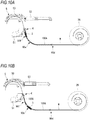
- FIG. 10A depicts an arrangement example of the wire feeding unit 3 and the guide part 100A of the reinforcing bar binding machine 1A in accordance with the third modified embodiment.
- a feeding path passing through a lower side in the main body 10 from the reel accommodation unit 2 is referred to as a lower side path 90d
- a feeding path provided downstream of the lower side path 90d and having a bending portion is referred to as a curved path 90e
- a feeding path between a downstream side of the curved path 90e and the cutting unit 6 is referred to as an intermediate path 90f.
- the guide part 100A is arranged between a downstream side of the lower side path 90d and the curved path 90e.
- the wire feeding unit 3 is arranged on the intermediate path 90f on a downstream side of the guide part 100A.
- the guide part 100B or the guide part 100C may also be applied, instead of the guide part 100A.
- FIG. 10B depicts an arrangement example of the wire feeding unit 3 and the guide part 100A of the reinforcing bar binding machine 1A in accordance with the fourth modified embodiment. Note that, the common descriptions to the third modified embodiment are omitted.
- the guide parts 100A are arranged at two places, i.e., on a downstream side of the lower side path 90d and on the intermediate path 90f.
- the wire feeding unit 3 is arranged on the curved path 90e and between the guide parts 100A and 100A at the two places.
- the guide part 100B or the guide part 100C may also be applied, instead of the guide part 100A.
- FIG. 10C depicts an arrangement example of the wire feeding unit 3 and the guide part 100A of the reinforcing bar binding machine 1A in accordance with the fifth modified embodiment. Note that, the common descriptions to the third modified embodiment are omitted.
- the guide parts 100A are arranged at two places, i.e., between the curved path 90e and the intermediate path 90f and at a part of the lower side path 90d.
- the wire feeding unit 3 is arranged on a downstream side of the lower side path 90d and between the guide parts 100A and 100A at the two places.
- the guide part 100B or the guide part 100C may also be applied, instead of the guide part 100A.
- FIG. 10D depicts an arrangement example of the wire feeding unit 3 and the guide part 100A of the reinforcing bar binding machine 1A in accordance with the sixth modified embodiment. Note that, the common descriptions to the third modified embodiment are omitted.
- the guide parts 100A are arranged at two places, i.e., on an upstream side of the lower side path 90d and from a substantially intermediate position of the lower side path 90d to the intermediate path 90f via the curved path 90e.
- the wire feeding unit 3 is arranged on the lower side path 90d and between the guide parts 100A and 100A arranged at the two places.
- the guide part 100B or the guide part 100C may also be applied, instead of the guide part 100A.
- FIG. 10E depicts an arrangement example of the wire feeding unit 3 and the guide part 100A of the reinforcing bar binding machine 1A in accordance with the seventh modified embodiment. Note that, the common descriptions to the third modified embodiment are omitted.
- the guide parts 100A are arranged at two places, i.e., on a downstream side of the lower side path 90d and on the curved path 90e.
- the wire feeding units 3 are arranged at two places, i.e., between the guide parts 100A and 100A at two places on a downstream side of the lower side path 90d, and on the intermediate path 90f.
- the guide part 100B or the guide part 100C may also be applied, instead of the guide part 100A.
- FIG. 11 is a side view of a reinforcing bar binding machine 1B in accordance with an eighth modified embodiment
- FIG. 12 is a perspective view of the reinforcing bar binding machine 1B in accordance with the eighth modified embodiment.
- the constitutional elements having substantially the same functional configurations as the reinforcing bar binding machine 1A are denoted with the same reference signs, and the overlapping descriptions are omitted.
- the longitudinal direction of the main body 10 is referred to as the front and rear direction
- the side on which the curl forming unit 5 is provided is referred to as a front side or tip end-side of the reinforcing bar binding machine 1B
- the side on which the reel accommodation unit 2 is provided is referred to as a rear side of the reinforcing bar binding machine 1B
- the side on which the battery 15 is provided and which is a direction orthogonal to the front and rear direction is referred to as a lower side of the reinforcing bar binding machine 1B, and the opposite side thereto is referred to as an upper side of the reinforcing bar binding machine 1B.
- the grip 11 extends substantially downward from a lower surface that is a substantially intermediate part of the main body 10 in the longitudinal direction and a part of a circumferential surface of the main body 10.
- the grip 11 is provided below the twisting shaft 72 extending in the front and rear direction of the main body 10, and is arranged on an opposite side to the feeding path 90 of the wire W provided in the main body 10 with the twisting shaft 72 being interposed therebetween.
- the curl guide 50 is arranged below the twisting shaft 72, and is arranged on the same side as the grip 11 with respect to the twisting shaft 72.
- the feeding path 90 is arranged above the twisting shaft 72 and on an upper side in the main body 10.
- the feeding path 90 may be provided with the guide part 100A, 100B, 100C, the buckling prevention part 200 and the wear prevention part 300. Even with the reinforcing bar binding machine 1B of the eighth modified embodiment, it is possible to achieve the similar operational effects to the reinforcing bar binding machine 1A.
- the reinforcing bar binding machine 1A and the like where the to-be-bound object is surrounded by the curled wire W and the wire W is then pulled back have been described.
- the present disclosure is not limited thereto.
- the technology of the present embodiment where the reel accommodation unit is arranged at the rear part of the main body can also be applied to a reinforcing bar binding machine where the wire W is not pulled back after the curled wire W is wound around the to-be-bound object.
Landscapes
- Engineering & Computer Science (AREA)
- Mechanical Engineering (AREA)
- Architecture (AREA)
- Civil Engineering (AREA)
- Structural Engineering (AREA)
- Basic Packing Technique (AREA)
- Wire Processing (AREA)
- Hand Tools For Fitting Together And Separating, Or Other Hand Tools (AREA)
Abstract
Description
- The present disclosure relates to a binding machine.
- For concrete buildings, to-be-bound objects such as reinforcing bars are generally used so as to reinforce strength of a tensile force. Before placement of concrete buildings, the to-be-bound objects are bound with wires so that the reinforcing bars do not deviate from predetermined positions. In this case, if the binding by the wire is loosened, positions of the to-be-bound objects deviate, so that appropriate strength by the to-be-bound objects is not obtained. For this reason, it is required to firmly bind the to-be-bound objects by the wires.
- The following technology is suggested to address such problem. For example,
PTL 1 discloses a reinforcing bar binding machine configured to feed a wire in a loop shape and to wind the wire around reinforcing bars, to pull back the wire with maintaining a tip end of the wire and to wind the wire on the reinforcing bars, and to twist the wire, thereby binding the reinforcing bars with the wire. - [PTL 1]
JP-A-2003-34305 - However, according to the reinforcing bar binding machine disclosed in
PTL 1, a wire reel is arranged on a front side of the main body. Therefore, when binding the to-be-bound objects for a complex building, the to-be-bound objects cannot be inserted into the reinforcing bar binding machine because a reel accommodation unit is provided on the front side of the main body, so that the to-be-bound objects cannot be bound. In some binding machines where the wire is not pulled back after the wire is wound on the to-be-bound object, the reel accommodation unit is arranged on a rear side of the main body. However, when feeding the wire, a wire feeding defect may occur or a feeding path in the binding machine is worn due to friction with the wire. - It is therefore an object of the present invention to provide a binding machine capable of preventing a wire feeding defect, wear of a feeding path in the binding machine, and the like even when a reel accommodation unit is arranged on a rear side of a main body.
- According to an aspect of the present disclosure, there is provided a binding machine configured to feed a wire in a first direction, to curl the wire, to surround a to-be-bound object with the wire, to return the wire in a second direction opposite to the first direction, to wind the wire on the to-be-bound object, and to twist the wire, thereby binding the to-be-bound object, the binding machine comprising: a main body; a reel accommodation unit configured to rotatably accommodate a reel on which the wire is wound; a wire feeding unit provided in the main body and configured to feed the wire in the first direction and in the second direction; a curl forming unit provided on a tip end-side of the main body and configured to curl the wire fed by the wire feeding unit; a binding unit comprising a twisting shaft extending from the tip end-side to a rear end-side of the main body, and configured to twist the wire curled by the curl forming unit by rotation of the twisting shaft; a grip extending from a circumferential surface of the main body; a starter provided to the grip and configured to start the wire feeding unit; and a feeding path provided in the main body for feeding the wire in the first direction or in the second direction, wherein the reel accommodation unit is provided in the main body on an opposite side to the curl forming unit with respect to the starter, and wherein the feeding path is provided with a load reducing part configured to reduce a load of the wire or the reel accommodation unit.
- According to an aspect of the present disclosure, since the reel accommodation unit is provided in the main body at the rear of the starter, it is possible to bind the to-be-bound object even though it is complex. In addition, since the feeding path is provided with the load reducing part, it is possible to reduce the load to the wire or the reel accommodation unit when feeding or returning the wire.
-
-
FIG. 1 is a side view of a reinforcing bar binding machine of the present embodiment. -
FIG. 2 is a perspective view of the reinforcing bar binding machine of the present embodiment. -
FIG. 3 is a side view depicting a state where a cover body of a reel accommodation unit of the reinforcing bar binding machine of the present embodiment is opened. -
FIG. 4 is a perspective view depicting the state where the cover body of the reel accommodation unit of the reinforcing bar binding machine of the present embodiment is opened. -
FIG. 5A is a side view depicting an internal configuration of the reinforcing bar binding machine of the present embodiment. -
FIG. 5B is a sectional view depicting the internal configuration of the reinforcing bar binding machine of the present embodiment. -
FIG. 6A depicts the cover body of the reel accommodation unit of the reinforcing bar binding machine of the present embodiment. -
FIG. 6B depicts a modified embodiment of the reel accommodation unit. -
FIG. 7 is a sectional view depicting a guide part of the present embodiment. -
FIG. 8A is a sectional view taken along a line A-A of the reinforcing bar binding machine shown inFIG. 3 , depicting a buckling prevention part. -
FIG. 8B is a sectional view taken along the line A-A of the reinforcing bar binding machine, depicting a case where the buckling prevention part shown inFIG. 3 is not provided. -
FIG. 9A is a sectional view of a guide part of the reinforcing bar binding machine in accordance with a first modified embodiment. -
FIG. 9B is a sectional view of a guide part of the reinforcing bar binding machine in accordance with a second modified embodiment. -
FIG. 10A depicts an arrangement example of the guide part and the wire feeding unit of the reinforcing bar binding machine in accordance with a third modified embodiment. -
FIG. 10B depicts an arrangement example of the guide part and the wire feeding unit of the reinforcing bar binding machine in accordance with a fourth modified embodiment. -
FIG. 10C depicts an arrangement example of the guide part and the wire feeding unit of the reinforcing bar binding machine in accordance with a fifth modified embodiment. -
FIG. 10D depicts an arrangement example of the guide part and the wire feeding unit of the reinforcing bar binding machine in accordance with a sixth modified embodiment. -
FIG. 10E depicts an arrangement example of the guide part and the wire feeding unit of the reinforcing bar binding machine in accordance with a seventh modified embodiment. -
FIG. 11 is a side view of a reinforcing bar binding machine in accordance with an eighth modified embodiment. -
FIG. 12 is a perspective view of the reinforcing bar binding machine in accordance with the eighth modified embodiment. - Hereinbelow, favorable embodiments of the present disclosure will be described in detail with reference to the accompanying drawings.
-
FIG. 1 is a side view of a reinforcing barbinding machine 1A of the present embodiment,FIG. 2 is a perspective view of the reinforcingbar binding machine 1A,FIG. 3 is a side view depicting a state where acover body 22 of areel accommodation unit 2 of the reinforcing barbinding machine 1A is opened,FIG. 4 is a perspective view depicting the state where thecover body 22 of thereel accommodation unit 2 of the reinforcingbar binding machine 1A is opened,FIG. 5A is a side view depicting an internal configuration of the reinforcingbar binding machine 1A,FIG. 5B is a sectional view depicting the internal configuration of the reinforcingbar binding machine 1A,FIG. 6A depicts thecover body 22 of thereel accommodation unit 2, andFIG. 6B depicts a modified embodiment of thereel accommodation unit 2. - In the present embodiment, a longitudinal direction of the main body 10 (a direction corresponding to the right and left direction in
FIG. 1 ) is referred to as the front and rear direction, a side on which acurl forming unit 5 is provided is referred to as a front side or a tip end-side of the reinforcingbar binding machine 1A, and a side on which areel accommodation unit 2 is provided is referred to as a rear side of the reinforcingbar binding machine 1A. A side on which abattery 15 is provided and which is a direction orthogonal to the front and rear direction is referred to as a lower side of the reinforcingbar binding machine 1A, and an opposite side thereto is referred to as an upper side of the reinforcing barbinding machine 1A. A side (an inner side of the drawing sheet ofFIG. 1 ) on which atwisting motor 80 is provided and which is orthogonal to the front and rear direction and the upper and lower direction of the reinforcingbar binding machine 1A is referred to as a right side of the reinforcingbar binding machine 1A, and a side (a front side of the drawing sheet ofFIG. 1 ) on which thereel accommodation unit 2 is provided is referred to as a left side of the reinforcingbar binding machine 1A. - In the present embodiment, a direction in which a
feeding motor 30 is rotated forward to feed a wire W from a wire feeding unit 3-side toward a curl forming unit 5-side is referred to as a forward direction (first direction), and a direction in which thefeeding motor 30 is reversely rotated to feed the wire W from the curl forming unit 5-side toward the wire feeding unit 3-side is referred to as a reverse direction (second direction). - As shown in
FIGS. 1 to 5B and the like, the reinforcingbar binding machine 1A includes amain body 10 having an elongated cuboid shape, areel accommodation unit 2 in which a wire W is accommodated, awire feeding unit 3 configured to feed the wire W in the forward direction and in the reverse direction, and acurl forming unit 5 configured to wind the wire W fed by thewire feeding unit 3 around reinforcing bars S. The reinforcingbar binding machine 1A also includes acutting unit 6 configured to cut the wire wound on the reinforcing bars S by thewire feeding unit 3, abinding unit 7 configured to twist the wire W wound on the reinforcing bars S, and adrive unit 8 configured to drive the bindingunit 7. According to the reinforcingbar binding machine 1A, the wire W is fed in the forward direction and wound around the reinforcing bars S, which are a to-be-bound object, the wire W wound around the reinforcing bars S is fed in the reverse direction and is then wound on the reinforcing bars S, and the wire W is then twisted, so that the reinforcing bars S can be bound with the wire W. - As shown in
FIG. 1 and the like, themain body 10 is provided therein with a feedingpath 90 for feeding the wire W in the forward direction or in the reverse direction. The feedingpath 90 is formed with extending between thereel accommodation unit 2 and thecurl forming unit 5 in themain body 10, below a twistingshaft 72 extending between the tip end-side and the rear end-side of themain body 10, more specifically, on a lower side in themain body 10. - As shown in
FIGS. 1 to 6A , in thereel accommodation unit 2, areel 26 on which the wire W is wound to be reeled out is rotatably accommodated and is also accommodated to be detachable and replaceable with respect to themain body 10. Thereel accommodation unit 2 is arranged at a rear part of themain body 10 at the rear of atrigger 12. Thereel accommodation unit 2 is arranged at a position offset in a left direction orthogonal to an axis direction of the twistingshaft 72, with respect to thewire feeding unit 3, - The
reel accommodation unit 2 has aconcave part 20 formed on aleft sidewall 10a of themain body 10, and acover body 22 for opening/closing theconcave part 20. Theconcave part 20 has a size capable of accommodating aflange part 26b (refer toFIG. 6A ) on one side of thereel 26 having a substantially circular cylinder shape, and has areel support part 21 configured to rotatably support thereel 26. - As shown in
FIG. 6A , thecover body 22 has aperipheral wall 22a having a cylindrical shape, anend wall 22b for covering one opening of theperipheral wall 22a, anentry 22c for the wire W formed at a part of theperipheral wall 22a, and apath cover 22d configured to communicate with theentry 22c and to cover a part (asecond path 90b to be described later) of the feedingpath 90. An upper end portion of theperipheral wall 22a is provided with arotation portion 22e for rotatably attaching thecover body 22 to themain body 10. Therotation portion 22e of thecover body 22 is attached to anattachment portion 10e (refer toFIG. 2 ) formed at themain body 10, so that thecover body 22 can rotate about therotation portion 22e as a support point. When thecover body 22 is opened, thereel 26 can be set in theconcave part 20 and thereel 26 set in theconcave part 20 can be taken out. On the other hand, when thecover body 22 is closed, thecover body 22 is locked to themain body 10 by a lock mechanism (not shown). - In the present embodiment, a rotary shaft of the
rotation portion 22e of thecover body 22 is arranged in the longitudinal direction of themain body 10, as shown inFIG. 2 and the like. However, as shown inFIG. 6B , the rotary shaft of therotation portion 22e may be arranged in a width direction (right and left direction) of themain body 10 so that thereel 26 can be set from the rear of themain body 10, and thecover body 22 may be configured to be opened and closed with respect to the rear of themain body 10. In this case, for example, theattachment portion 10e is provided at a rear end portion of a lower surface-side of themain body 10, and thecover body 22 is configured to be rotatable about the rotary shaft (support point) of therotation portion 22e of thecover body 22. In addition, an upper end portion of thecover body 22 may be provided with a lock mechanism 23 so that thecover body 22 can be locked to themain body 10. Furthermore, therotation portion 22e and theattachment portion 10e may be provided on an upper side of the main body opposite toFIG. 6B . Also, thereel accommodation unit 2 may be arranged at a position further offset rearward than the twistingmotor 80 in a state where therotation portion 22e is provided in the longitudinal direction as shown inFIG. 1 . In this case, thereel accommodation unit 2 may be arranged offset or without being offset with respect to the twistingmotor 80. - As shown in
FIG. 4 , thereel 26 has acylindrical hub part 26a on which the wire W is to be wound, and a pair offlange parts hub part 26a. One or more wires W are wound on thehub part 26a of thereel 26, and the wire W can be pulled out from thereel 26. For the wire W, a wire made of a plastically deformable metal wire, a wire having a metal wire covered with a resin, a twisted wire and the like are used. - As shown in
FIG. 1 and the like, agrip 11 extends substantially downward from a lower surface that is a substantially intermediate part of themain body 10 in the longitudinal direction and a part of a circumferential surface of themain body 10. In other words, thegrip 11 is provided below the twistingshaft 72 extending in the front and rear direction of themain body 10. An upper end portion of thegrip 11 is provided on its front surface with atrigger 12 that is an example of the starter. When thetrigger 12 is pulled by a user in a state where a power supply is on, a binding operation is executed. Abattery 15 that configures a power supply unit is detachably attached to a lower part of thegrip 11. - As shown in
FIGS. 5A and 5B , thewire feeding unit 3 includes a pair of first and second feeding gears, and is configured to feed the wire W with sandwiching the wire W between grooves formed on gear teeth of the first feeding gear and grooves formed on gear teeth of the second feeding gear. The first feeding gear of thewire feeding unit 3 is connected, for example, to a feedingmotor 30, so that it is rotated by drive of the feedingmotor 30. The second feeding gear of thewire feeding unit 3 is driven to rotate in connection with rotation of the first feeding gear. In a case where a rotation direction of the feedingmotor 30 is a forward rotation direction, thewire feeding unit 3 feeds the wire W in the forward direction, and in a case where the rotation direction of the feedingmotor 30 is switched to a reverse rotation direction, thewire feeding unit 3 feeds the wire W in a reverse direction. - As shown in
FIGS. 1 and5B , thecurl forming unit 5 is provided on the tip end-side of themain body 10 and above the twistingshaft 72. Thecurl forming unit 5 includes acurl guide 50 configured to curl the wire W that is fed by thewire feeding unit 3, and aninduction guide 51 configured to guide the wire W curled by thecurl guide 50 toward thebinding unit 7. - As shown in
FIG. 5B and the like, thecurl guide 50 has aguide groove 52 configuring a feeding path of the wire W, and afirst guide pin 53a and asecond guide pin 53b configured to curl the wire W in cooperation with theguide groove 52. Thefirst guide pin 53a is arranged on an upstream side of thecurl guide 50 with respect to the forward direction, i.e., on an introduction side of the wire W and on an inner side with respect to the passing wire W. Thesecond guide pin 53b is arranged on a downstream side of thecurl guide 50 with respect to the forward direction, i.e., on a discharge side of the wire W and on an outer side with respect to the passing wire W. - The
curl forming unit 5 includes aretreat mechanism 53 configured to retreat thefirst guide pin 53a. When feeding the wire W in the reverse direction by thewire feeding unit 3, theretreat mechanism 53 retreats thefirst guide pin 53a from the feeding path along which the wire W wound on the reinforcing bars S moves. - As shown in
FIGS. 5A and 5B , thecutting unit 6 has a fixedblade part 60, amovable blade part 61 configured to cut the wire W in cooperation with the fixedblade part 60, and atransmission mechanism 62 configured to transmit an operation of thebinding unit 7 to themovable blade part 61. Themovable blade part 61 is configured to rotate about the fixedblade part 60 as a support axis by the operation of thebinding unit 7 transmitted by thetransmission mechanism 62, thereby cutting the wire W in cooperation with the fixedblade part 60. - As shown in
FIGS. 5A and 5B , the bindingunit 7 includes an engagingmember 70 to which the wire W is to be engaged, an actuatingmember 71 configured to open/close the engagingmember 70, and a twistingshaft 72 for actuating the engagingmember 70 and the actuatingmember 71. The engagingmember 70 is configured to operate in conjunction with movement of the actuatingmember 71, to hold a portion of the wire W in a movable state before passing through thecurl forming unit 5, and to hold a portion of the wire W in a state where it does not come off from the engagingmember 70 after passing through thecurl forming unit 5. The actuatingmember 71 moves forward, thereby bending end portions of the wire W held on the tip end-side of the engagingmember 70 toward the reinforcing bars S. - As shown in
FIGS. 5A and 5B , thedrive unit 8 includes a twistingmotor 80, and adecelerator 81 for deceleration and torque amplification. The twistingshaft 72 and the twistingmotor 80 are connected via thedecelerator 81, so that the twistingshaft 72 is rotated by drive of the twistingmotor 80 via thedecelerator 81. - The reinforcing
bar binding machine 1A of the present embodiment also includes aguide part 100A, a bucklingprevention part 200 and awear prevention part 300, which are included in a load reducing part. - First, the
guide part 100A is described.FIG. 7 is a sectional view depicting theguide part 100A of the present embodiment. As shown inFIG. 7 , theguide part 100A is provided between the wire feeding unit 3 (refer toFIG. 5A ) and thecutting unit 6, and guides the wire W when feeding the wire W to thecurl forming unit 5 and when pulling back the wire W fed to thecurl forming unit 5. Here, before describing theguide part 100A, a problem that occurs in thefeeding path 90 when thereel accommodation unit 2 is arranged at the rear part of themain body 10 is described. - When the
reel accommodation unit 2 is arranged at a rear part of themain body 10, the wire W is fed to thecurl forming unit 5 through the feeding path formed above or below the twistingshaft 72 in themain body 10. In a reinforcing bar binding machine where the reinforcing bars S are surrounded by the wire W and the wire W is then returned, since it is necessary to cross the wire W at thebinding unit 7, thecurl forming unit 5 is arranged on an opposite side to the feeding path of the wire W. In the reinforcingbar binding machine 1A of the present embodiment, as shown inFIG. 1 , when the feedingpath 90 of the wire W is provided on a lower side in themain body 10, thecurl forming unit 5 is arranged above the twistingshaft 72. - For this reason, in order to feed the wire W from the feeding
path 90 on the lower side in themain body 10 to thecurl forming unit 5 on the upper side, a feeding path having a bending portion should be provided between thewire feeding unit 3 and thecurl forming unit 5. In this case, a curvature of the feeding path of the wire W is reduced. Therefore, when feeding the wire W in the forward direction or in the reverse direction, the wire W is contacted to the bending portion in the feeding path and a load resistance against the wire W increases, so that a feeding defect of the wire W may be caused. Therefore, in the present embodiment, theguide part 100A for reducing the load resistance when feeding and returning the wire W is provided between thewire feeding unit 3 and thecurl forming unit 5. Note that, in the present embodiment, a feeding path having a bending portion, which is provided between thewire feeding unit 3 and thecurl forming unit 5, of the feedingpath 90 is referred to as afirst path 90a. - In the present embodiment, as shown in
FIG. 7 , theguide part 100A includes a pipe 100 having a diameter larger than a diameter of the wire W. Thepipe 110 is curved from thewire feeding unit 3 toward the curl forming unit 5 (cutting unit 6), and functions as thefirst path 90a of the wire W between thewire feeding unit 3 and thecurl forming unit 5. A downstream end portion of thepipe 110 is attached to aplate 63 configuring thecutting unit 6, for example. An upstream end portion of thepipe 110 extends ahead of thewire feeding unit 3 and has a wider diameter than other portion so that the wire W can be easily inserted therein, so that an opening area is large. Thepipe 110 is formed of a low friction material capable of reducing the load resistance upon contact of the wire W that is fed by thewire feeding unit 3. Examples of the low friction material include self-lubricating composite materials such as dry bearings, and a surface treatment such as hard chromium plating and vanadium carbide coating can be used. More preferably, thepipe 110 has high wear resistance. - Subsequently, the buckling
prevention part 200 is described.FIG. 8A is a sectional view taken along a line A-A of the reinforcingbar binding machine 1A shown inFIG. 3 , depicting the bucklingprevention part 200 of the present embodiment.FIG. 8B depicts a state of the wire in a case where the bucklingprevention part 200 is not provided. Note that, a feeding path, which is provided between thereel accommodation unit 2 and thewire feeding unit 3, of the feedingpath 90 is referred to as asecond path 90b. - As shown in
FIG. 8A , the bucklingprevention part 200 is provided on thesecond path 90b connecting thereel accommodation unit 2 and thewire feeding unit 3, and prevents buckling of the wire W by supporting a portion of the wire W when returning the wire W. Here, before describing the bucklingprevention part 200, a problem of the buckling of the wire W that occurs on thesecond path 90b when thereel accommodation unit 2 is arranged at the rear part of themain body 10 is described. - When returning the wire W, the
reel 26 is a little rotated or is barely rotated by a returning amount (urging force) during returning of the wire W because the reel is a driven member. For this reason, during the returning, the wire W spreads toward abottom wall 10b of thesecond path 90b and is pushed and fed to the upstream side of thereel accommodation unit 2, as shown with the wire W of the broken line inFIG. 3 . Thereby, when returning the wire W, a compression force is applied to the wire W spread toward thebottom wall 10b from the wire feeding unit 3-side toward the reel accommodation unit 2-side, so that the wire W is buckled. Note that, during the returning, since the wire W is fed stretched from thereel 26 by drive of thewire feeding unit 3, the wire W passes through a wire path shown with the solid line inFIG. 3 . - Here, a buckling theory of the wire W is described. The buckling refers to a phenomenon that when a load applied to a structure (to-be-bound object) is gradually increased, a deformation manner suddenly changes at certain load, thereby causing large deflection or bending in the structure. The load at which the buckling phenomenon is caused in a structure is referred to as a buckling load of the structure. The buckling load is expressed by a following equation (1).

- In the equation (1), Pk is a buckling load (also referred to as buckling-bearing strength), E is a Young's modulus, I is a cross-sectional secondary moment, and L is a buckling length (a distance between support points).
- The buckling load Pk means that even when the buckling load Pk is applied, the buckling is not caused in the structure. For this reason, when the buckling length L is shorter, the buckling load Pk increases and the buckling of the wire W is more difficult to occur. Therefore, as shown in
FIG. 8B , when a distance between support points between thewire feeding unit 3 and thereel 26 is set as the buckling length L, the buckling load Pk is reduced, so that the buckling is likely to occur when returning the wire W. - In contrast, according to the present embodiment, as shown in
FIG. 8A , the bucklingprevention part 200 configured to support a portion of the wire W when returning the wire W is provided on thebottom wall 10b of thesecond path 90b between thereel accommodation unit 2 and thewire feeding unit 3, for example. The bucklingprevention part 200 includes, for example, at least afirst surface 201 having a larger inclination than an inclination of the wire W during the returning, and asecond surface 202 having a smaller inclination than the inclination of the wire W. An end side on an upstream side of thefirst surface 201 and an end side on a downstream side of thesecond surface 202 are connected to each other, and the connection part configures asupport part 203 that is to contact the wire W. - The buckling
prevention part 200 is provided on the way of thesecond path 90b between thewire feeding unit 3 and thereel 26, so that the buckling length L shown inFIG. 8B can be divided into a buckling length L1 between thewire feeding unit 3 and supportpart 203 and a buckling length L2 between thesupport part 203 and thereel 26, as shown inFIG. 8A . Therefore, the buckling length L shown inFIG. 8B can be set substantially short, and the buckling load Pk in the equation (1) in each section of the buckling lengths L1 and L2 can be increased. Thereby, it is possible to prevent the buckling on thesecond path 90b when returning the wire W. - Subsequently, the
wear prevention part 300 is described. As shown inFIGS. 4 and6A , and the like, thewear prevention part 300 is configured to reduce the friction between the wire W and thereel accommodation unit 2 during the returning of the wire W or to protect thereel accommodation unit 2 by a rigid material, thereby preventing the wear of thereel accommodation unit 2. Before describing thewear prevention part 300, a problem of the wear that occurs in thereel accommodation unit 2 when thereel accommodation unit 2 is arranged at the rear part of themain body 10 is described. - When returning the wire W, the
reel 26 is barely rotated or is a little rotated by the returning amount (urging force) during the returning of the wire W because the reel is a driven member. For this reason, during the returning, the wire W is fed spreading in an outer periphery direction of theperipheral wall 22a of thecover body 22 of thereel accommodation unit 2, as shown with the wire W of the broken line inFIG. 3 . Thereby, the wire W is contacted in thereel accommodation unit 2, so that a predetermined part of thereel accommodation unit 2 is rubbed and worn. - Here, a logical equation of the wear is expressed by a following equation (2).

- In the equation (2), W is an estimated wear size, K is a specific wear amount, P is a load surface pressure, V is a sliding velocity, and T is a friction time.
- As can be clearly seen from the equation (2), the wear amount K correlates with the load surface pressure P and the sliding velocity V. Thereby, it can be seen that the wear of the machine including the
reel accommodation unit 2 and the like is more likely to occur in a part where the load surface pressure P × the sliding velocity V (hereinbelow, referred to as PV value) is larger. Therefore, in the present embodiment, thewear prevention part 300 is provided at a position in thereel accommodation unit 2, which is likely to be worn. The position in thereel accommodation unit 2, which is likely to be worn, is described as follows, for example. - As shown in
FIGS. 3 and6A , in a position P1 in the vicinity of the entry 2c of thereel accommodation unit 2, a moving velocity of the wire W is high but a force in the returning direction is high and a pressure with which the wire W contacts thereel accommodation unit 2 and the load surface pressure P are relatively lower. However, the wire W is contacted to thereel accommodation unit 2, so that thereel accommodation unit 2 and the like are a little worn. - On a further upstream side in the
reel accommodation unit 2 than the position P1, specifically, in a position P2 on a lower part-side in thereel accommodation unit 2, the wire W spreads in the outer periphery direction of thereel 26 and is contacted to an inner peripheral surface 22a1 of thereel accommodation unit 2, and the like. In the position P2, the moving velocity of the wire is also high when returning the wire W. For this reason, the PV value is greatest, and the wear amounts of thereel accommodation unit 2 and the like also increase. - In addition, on a further upstream side in the
reel accommodation unit 2 than the position P2, specifically, in a position P3 substantially flush with thehub part 26a of thereel 26 in thereel accommodation unit 2, the returning velocity of the wire W gradually decreases. For this reason, the PV value decreases, so that the wear amounts of thereel accommodation unit 2 and the like are smaller than at the second position P2. - Therefore, in the present embodiment, the
wear prevention part 300 consisting of a rigid plate, for example, is provided on thesecond path 90b and at a position including the first position P1, the second position P2 and the third position P3 in thereel accommodation unit 2. As shown inFIGS. 4 and6A , thewear prevention part 300 has afirst plate 301 provided on the inner peripheral surface 22a1 of thereel accommodation unit 2, asecond plate 302 provided on asidewall 10c configuring thesecond path 90b, and athird plate 303 provided extending between thebottom wall 10b configuring thesecond path 90b and an inside of thereel accommodation unit 2. - Note that, the
wear prevention part 300 may be provided only at the second position P2 at which the wear amount is large or may be provided only at the second position P2 and the third position P3 at which the wear amount is the first and second largest. In addition, a thickness of thewear prevention part 300 may be adjusted to be stepwise reduced in descending order of the wear amount. In the present embodiment, thewear prevention part 300 is configured by the rigid plate. However, the present disclosure is not limited thereto. For example, a member capable of preventing wear due to the wire W can be adopted as appropriate. Also, thewear prevention part 300 is configured as a separate member from thereel accommodation unit 2. However, thereel accommodation unit 2 itself may be formed of a high hardness material. - Subsequently, an operation of binding the reinforcing bars S with one wire W by the reinforcing
bar binding machine 1A is described with reference to the respective drawings. Note that, the reinforcingbar binding machine 1A is in a standby state where the wire W is sandwiched by thewire feeding unit 3 and the tip end of the sandwiched wire W is positioned between thewire feeding unit 3 and thecutting unit 6 or the tip end of the wire W is position in thecutting unit 6. - When the reinforcing bars S, which are a to-be-bound object, are inserted between the
curl guide 50 and theinduction guide 51 of thecurl forming unit 5 and thetrigger 12 is operated, the feedingmotor 30 is driven in the forward rotation direction, so that thewire feeding unit 3 is rotated in the forward direction. Thereby, the wire W is fed in the forward direction. In the present embodiment, theguide part 100A is provided between thewire feeding unit 3 and thecurl forming unit 5. Therefore, the friction between the wire W and theguide part 100A when feeding the wire W can be reduced, so that the load resistance of the wire W is reduced. - When the wire W is fed in the forward direction, the wire W passes through the tip end of the engaging
member 70 and also passes through thecurl guide 50 of thecurl forming unit 5. Thereby, the wire W is curled by thefirst guide pin 53a and thesecond guide pin 53b, etc. - The wire W curled by the
curl guide 50 is guided to theinduction guide 51 and is further fed in the forward direction by thewire feeding unit 3, so that the wire passes through the tip end of the engagingmember 70 and is butted against afeeding regulation part 9. The drive of the feedingmotor 30 is stopped. - After stopping the feeding of the wire W in the forward direction, the twisting
motor 80 is driven in the forward rotation direction. The rotation of the twistingmotor 80 is converted into linear movement via the twistingshaft 72 and the like, so that the actuatingmember 71 is moved forward. When the actuatingmember 71 is moved forward, a portion of the wire W before passing through thecurl forming unit 5 is held so as to be movable by the engagingmember 70, and the wire W after passing through thecurl forming unit 5 is held so as not to come off from the engagingmember 70 by the engagingmember 70. - In addition, when the actuating
member 71 is moved forward, the operation of the actuatingmember 71 is transmitted to theretreat mechanism 53, so that thefirst guide pin 53a is retreated. - Continuously, the rotation of the twisting
motor 80 is temporarily stopped, and the feedingmotor 30 is driven in the reverse rotation direction. Thereby, thewire feeding unit 3 is reversely rotated, so that the wire W sandwiched by thewire feeding unit 3 is fed in the reverse direction. Since the tip end of the wire W is held by the engagingmember 70, the wire W is wound so as to closely contact the reinforcing bars S. - In the present embodiment, since the
second path 90b is provided with the bucklingprevention part 200, a portion of the wire W that is fed in the reverse direction when returning the wire W is supported by thesupport part 203. Thereby, since the buckling load of the wire W can be increased, the buckling of the wire W on thesecond path 90b is prevented. In addition, since thereel accommodation unit 2 is provided with thewear prevention part 300, even when the wire W that is fed in the reverse direction spreads in the outer periphery direction of thereel 26, the wear of thereel accommodation unit 2 due to the contact of the wire W is prevented. - After stopping the feeding
motor 30, the twistingmotor 80 is driven in the forward rotation direction, so that the actuatingmember 71 is moved forward and the wire W held by the engagingmember 70 is cut by the operations of the fixedblade part 60 and themovable blade part 61. - After the wire W is cut, the end portions of the wire W are each bent toward the reinforcing bars S. After the end portions of the wire W are bent, the twisting
motor 80 is further driven in the forward rotation direction, so that the actuatingmember 71 rotates in conjunction with the twistingshaft 72 and the engagingmember 70 holding the wire W rotates integrally with the actuatingmember 71, thereby twisting the wire W. - As described above, according to the present embodiment, the
reel accommodation unit 2 is provided at the rear of thetrigger 12, specifically, at the rear part of themain body 10. Therefore, for example, even when binding a to-be-bound object having a complex structure, thereel accommodation unit 2 is not an obstacle and the to-be-bound object can be smoothly inserted between thecurl guide 50 and theinduction guide 51. Thereby, the reinforcingbar binding machine 1A can be used for the to-be-bound objects of several structures. - In addition, according to the present embodiment, even when the
reel accommodation unit 2 is provided at the rear part of themain body 10, since thefirst path 90a having the bending portion is configured by theguide part 100A, it is possible to reduce the load resistance of the wire W against thefirst path 90a when feeding and returning the wire W. Thereby, it is possible to prevent the wire W from slipping in thewire feeding unit 3, so that it is possible to prevent the feeding defect of the wire W. - In addition, according to the present embodiment, since the
second path 90b is provided with the bucklingprevention part 200, a portion of the wire W can be supported by thesupport part 203 during the returning of the wire W. Thereby, since it is possible to disperse and reduce the load that is applied to the wire W, it is possible to prevent the buckling in the reinforcingbar binding machine 1A during the returning of the wire W, so that it is possible to avoid the binding defect and the machine failure. - Additionally, according to the present embodiment, since the
wear prevention part 300 is provided in thereel accommodation unit 2, it is possible to prevent the wear, which is caused as the wire W is contacted to the inner peripheral surface 22a1 of thereel accommodation unit 2 and the like, during the returning of the wire W. Thereby, it is possible to improve the durability of the reinforcingbar binding machine 1A including thereel accommodation unit 2. - Furthermore, according to the present embodiment, since the
reel accommodation unit 2 is offset in the axis direction of thereel 26 and in the left direction of the twistingmotor 80 with respect to thewire feeding unit 3, the feeding path of the wire W is obliquely directed from thewire feeding unit 3 toward thereel 26, so that it is possible to set a locus in a fixed direction when returning the wire W. Thereby, it is possible to limit the buckling places of the wire W and the wear places of thereel accommodation unit 2 and the like, so that it is possible to specify the arrangement places of the bucklingprevention part 200 and thewear prevention part 300. - Subsequently, a
guide part 100B of the reinforcingbar binding machine 1A in accordance with a first modified embodiment is described.FIG. 9A depicts theguide part 100B of the first modified embodiment. - As shown in
FIG. 9A , theguide part 100B is provided on thefirst path 90a formed between thewire feeding unit 3 and thecutting unit 6, and is configured to guide the wire W when feeding the wire W to thecurl forming unit 5 and when pulling back the wire W fed to thecurl forming unit 5. Thefirst path 90a is configured by a sidewall of a resin material, a metal material or the like, for example, and has a bending portion bent from thewire feeding unit 3 toward thecutting unit 6. Note that, thefirst path 90a may also be configured by a pipe, similarly to theguide part 100A. - The
guide part 100B hasrigid pins first path 90a. Therigid pins rigid pins main body 10. Note that, the material of therigid pin 120a and the like is not limited to stainless steel. For example, a known rigid material can be used as appropriate. - The
rigid pins first path 90a. Therigid pin 120c is located on an upper surface-side of thefirst path 90a between therigid pin 120a and therigid pin 120b. A part of a circumferential surface of each of therigid pins first path 90a, and can contact the wire W passing through the inside of thefirst path 90a. Even with theguide part 100B, it is possible to achieve the similar effects to theguide part 100A. - Subsequently, a guide part 100C of the reinforcing
bar binding machine 1A in accordance with a second modified embodiment is described.FIG. 9B depicts the guide part 100C of the second modified embodiment. Note that, the common descriptions to the first modified embodiment are omitted. - As shown in
FIG. 9B , the guide part 100C is provided on thefirst path 90a formed between thewire feeding unit 3 and thecutting unit 6, and is configured to guide the wire W when feeding the wire W to thecurl forming unit 5 and when pulling back the wire W fed to thecurl forming unit 5. The guide part 100C hasrollers first path 90a. Therollers rollers main body 10. - The
rollers first path 90a. Theroller 130c is located on an upper side of thefirst path 90a between theroller 130a and theroller 130b. A part of a circumferential surface of each of therollers first path 90a, and can contact the wire W passing through the inside of thefirst path 90a. Even with the guide part 100C, it is possible to achieve the similar effects to theguide part 100A. - Subsequently, an arrangement example of the
wire feeding unit 3 and theguide part 100A of the reinforcingbar binding machine 1A in accordance with a third modified embodiment is described.FIG. 10A depicts an arrangement example of thewire feeding unit 3 and theguide part 100A of the reinforcingbar binding machine 1A in accordance with the third modified embodiment. InFIG. 10A , a feeding path passing through a lower side in themain body 10 from thereel accommodation unit 2 is referred to as alower side path 90d, a feeding path provided downstream of thelower side path 90d and having a bending portion is referred to as acurved path 90e, and a feeding path between a downstream side of thecurved path 90e and thecutting unit 6 is referred to as anintermediate path 90f. - As shown in
FIG. 10A , theguide part 100A is arranged between a downstream side of thelower side path 90d and thecurved path 90e. Thewire feeding unit 3 is arranged on theintermediate path 90f on a downstream side of theguide part 100A. Note that, theguide part 100B or the guide part 100C may also be applied, instead of theguide part 100A. - Subsequently, an arrangement example of the
wire feeding unit 3 and theguide part 100A of the reinforcingbar binding machine 1A in accordance with a fourth modified embodiment is described.FIG. 10B depicts an arrangement example of thewire feeding unit 3 and theguide part 100A of the reinforcingbar binding machine 1A in accordance with the fourth modified embodiment. Note that, the common descriptions to the third modified embodiment are omitted. - As shown in
FIG. 10B , theguide parts 100A are arranged at two places, i.e., on a downstream side of thelower side path 90d and on theintermediate path 90f. Thewire feeding unit 3 is arranged on thecurved path 90e and between theguide parts guide part 100B or the guide part 100C may also be applied, instead of theguide part 100A. - Subsequently, an arrangement example of the
wire feeding unit 3 and theguide part 100A of the reinforcingbar binding machine 1A in accordance with a fifth modified embodiment is described.FIG. 10C depicts an arrangement example of thewire feeding unit 3 and theguide part 100A of the reinforcingbar binding machine 1A in accordance with the fifth modified embodiment. Note that, the common descriptions to the third modified embodiment are omitted. - As shown in
FIG. 10C , theguide parts 100A are arranged at two places, i.e., between thecurved path 90e and theintermediate path 90f and at a part of thelower side path 90d. Thewire feeding unit 3 is arranged on a downstream side of thelower side path 90d and between theguide parts guide part 100B or the guide part 100C may also be applied, instead of theguide part 100A. - Subsequently, an arrangement example of the
wire feeding unit 3 and theguide part 100A of the reinforcingbar binding machine 1A in accordance with a sixth modified embodiment is described.FIG. 10D depicts an arrangement example of thewire feeding unit 3 and theguide part 100A of the reinforcingbar binding machine 1A in accordance with the sixth modified embodiment. Note that, the common descriptions to the third modified embodiment are omitted. - As shown in
FIG. 10D , theguide parts 100A are arranged at two places, i.e., on an upstream side of thelower side path 90d and from a substantially intermediate position of thelower side path 90d to theintermediate path 90f via thecurved path 90e. Thewire feeding unit 3 is arranged on thelower side path 90d and between theguide parts guide part 100B or the guide part 100C may also be applied, instead of theguide part 100A. - Subsequently, an arrangement example of the
wire feeding unit 3 and theguide part 100A of the reinforcingbar binding machine 1A in accordance with a seventh modified embodiment is described.FIG. 10E depicts an arrangement example of thewire feeding unit 3 and theguide part 100A of the reinforcingbar binding machine 1A in accordance with the seventh modified embodiment. Note that, the common descriptions to the third modified embodiment are omitted. - As shown in
FIG. 10E , theguide parts 100A are arranged at two places, i.e., on a downstream side of thelower side path 90d and on thecurved path 90e. Thewire feeding units 3 are arranged at two places, i.e., between theguide parts lower side path 90d, and on theintermediate path 90f. Note that, theguide part 100B or the guide part 100C may also be applied, instead of theguide part 100A. -
FIG. 11 is a side view of a reinforcingbar binding machine 1B in accordance with an eighth modified embodiment, andFIG. 12 is a perspective view of the reinforcingbar binding machine 1B in accordance with the eighth modified embodiment. Note that, the constitutional elements having substantially the same functional configurations as the reinforcingbar binding machine 1A are denoted with the same reference signs, and the overlapping descriptions are omitted. In the eighth modified embodiment, the longitudinal direction of themain body 10 is referred to as the front and rear direction, the side on which thecurl forming unit 5 is provided is referred to as a front side or tip end-side of the reinforcingbar binding machine 1B, and the side on which thereel accommodation unit 2 is provided is referred to as a rear side of the reinforcingbar binding machine 1B. The side on which thebattery 15 is provided and which is a direction orthogonal to the front and rear direction is referred to as a lower side of the reinforcingbar binding machine 1B, and the opposite side thereto is referred to as an upper side of the reinforcingbar binding machine 1B. - The
grip 11 extends substantially downward from a lower surface that is a substantially intermediate part of themain body 10 in the longitudinal direction and a part of a circumferential surface of themain body 10. In other words, thegrip 11 is provided below the twistingshaft 72 extending in the front and rear direction of themain body 10, and is arranged on an opposite side to thefeeding path 90 of the wire W provided in themain body 10 with the twistingshaft 72 being interposed therebetween. Thecurl guide 50 is arranged below the twistingshaft 72, and is arranged on the same side as thegrip 11 with respect to the twistingshaft 72. The feedingpath 90 is arranged above the twistingshaft 72 and on an upper side in themain body 10. - Similarly to the reinforcing
bar binding machine 1A, the feedingpath 90 may be provided with theguide part prevention part 200 and thewear prevention part 300. Even with the reinforcingbar binding machine 1B of the eighth modified embodiment, it is possible to achieve the similar operational effects to the reinforcingbar binding machine 1A. - Although the favorable embodiments of the present disclosure have been described in detail with reference to the accompanying drawings, the technical scope of the present disclosure is not limited thereto. A variety of changes or modifications that can be conceived within the scope of the technical spirit defined in the claims by one skilled in the art of the present disclosure are included in the technical scope of the present disclosure.
- For example, in the above embodiments, the reinforcing
bar binding machine 1A and the like where the to-be-bound object is surrounded by the curled wire W and the wire W is then pulled back have been described. However, the present disclosure is not limited thereto. For example, the technology of the present embodiment where the reel accommodation unit is arranged at the rear part of the main body can also be applied to a reinforcing bar binding machine where the wire W is not pulled back after the curled wire W is wound around the to-be-bound object.
Claims (10)
- A binding machine configured to feed a wire in a first direction, to curl the wire, to surround a to-be-bound object with the wire, to return the wire in a second direction opposite to the first direction, to wind the wire on the to-be-bound object, and to twist the wire, thereby binding the to-be-bound object, the binding machine comprising:a main body;a reel accommodation unit configured to rotatably accommodate a reel on which the wire is wound;a wire feeding unit provided in the main body and configured to feed the wire in the first direction and in the second direction;a curl forming unit provided on a tip end-side of the main body and configured to curl the wire fed by the wire feeding unit;a binding unit comprising a twisting shaft extending from the tip end-side to a rear end-side of the main body, and configured to twist the wire curled by the curl forming unit by rotation of the twisting shaft;a grip extending from a circumferential surface of the main body;a starter provided to the grip and configured to start the wire feeding unit; anda feeding path provided in the main body for feeding the wire in the first direction or in the second direction,wherein the reel accommodation unit is provided in the main body on an opposite side to the curl forming unit with respect to the starter, andwherein the feeding path is provided with a load reducing part configured to reduce a load of the wire or the reel accommodation unit.
- The binding machine according to Claim 1, wherein the feeding path is provided between the wire feeding unit and the curl forming unit, and comprises a bending portion configured to bend the wire from the wire feeding unit toward the curl forming unit, and
wherein the load reducing part comprises a guide part configured to reduce friction of the wire against the bending portion when feeding the wire in the first direction or in the second direction. - The binding machine according to Claim 2, wherein the guide part includes a pipe having a diameter larger than a diameter of the wire.
- The binding machine according to any one of Claims 1 to 3, wherein the feeding path is provided between the reel accommodation unit and the wire feeding unit, and
wherein the load reducing part comprises a buckling prevention part configured to support the wire when feeding the wire in the second direction. - The binding machine according to Claim 4, wherein the buckling prevention part includes two surfaces which have different inclination, and
wherein a connection part where the two surfaces are connected to each other is configured to contact the wire. - The binding machine according to any one of Claims 1 to 5, wherein the feeding path is provided in the reel accommodation unit, and
wherein the load reducing part comprises a wear reducing part configured to reduce wear of the reel accommodation unit due to the wire when feeding the wire in the second direction. - The binding machine according to Claim 6, wherein the wear reducing part includes a plate provided in an inner peripheral surface on a lower part-side of the real accommodation unit.
- The binding machine according to any one of Claims 1 to 7, wherein the feeding path and the grip are provided on one side with respect to the twisting shaft, and
wherein the curl forming unit is provided on the other side with respect to the twisting shaft. - The binding machine according to any one of Claims 1 to 7, wherein the feeding path is provided on one side with respect to the twisting shaft, and
wherein the curl forming unit and the grip are provided on the other side with respect to the twisting shaft. - A binding machine configured to feed a wire in a first direction, to curl the wire, to surround a to-be-bound object with the wire, to return the wire in a second direction opposite to the first direction, to wind the wire on the to-be-bound object, and to twist the wire, thereby binding the to-be-bound object, the binding machine comprising:a main body;a reel accommodation unit configured to rotatably accommodate a reel on which the wire is wound;a wire feeding unit provided in the main body and configured to feed the wire in the first direction and in the second direction;a curl forming unit provided on a tip end-side of the main body and configured to curl the wire fed by the wire feeding unit;a binding unit comprising a twisting shaft extending from the tip end-side to a rear end-side of the main body, and configured to twist the wire curled by the curl forming unit by rotation of the twisting shaft;a grip extending from a circumferential surface of the main body;a starter provided to the grip and configured to start the wire feeding unit; anda feeding path provided in the main body for feeding the wire in the first direction or in the second direction,wherein the reel accommodation unit is provided in the main body on an opposite side to the curl forming unit with respect to the starter,wherein the feeding path and the grip are provided on one side with respect to the twisting shaft, andwherein the curl forming unit is provided on the other side with respect to the twisting shaft.
Applications Claiming Priority (1)
| Application Number | Priority Date | Filing Date | Title |
|---|---|---|---|
| JP2020021027A JP7508800B2 (en) | 2020-02-10 | 2020-02-10 | Binding machine |
Publications (3)
| Publication Number | Publication Date |
|---|---|
| EP3862513A1 true EP3862513A1 (en) | 2021-08-11 |
| EP3862513C0 EP3862513C0 (en) | 2025-12-03 |
| EP3862513B1 EP3862513B1 (en) | 2025-12-03 |
Family
ID=74586757
Family Applications (1)
| Application Number | Title | Priority Date | Filing Date |
|---|---|---|---|
| EP21156049.5A Active EP3862513B1 (en) | 2020-02-10 | 2021-02-09 | Binding machine |
Country Status (5)
| Country | Link |
|---|---|
| US (1) | US11905049B2 (en) |
| EP (1) | EP3862513B1 (en) |
| JP (2) | JP7508800B2 (en) |
| CN (1) | CN113247334B (en) |
| TW (1) | TWI857209B (en) |
Families Citing this family (3)
| Publication number | Priority date | Publication date | Assignee | Title |
|---|---|---|---|---|
| USD1002313S1 (en) * | 2022-03-25 | 2023-10-24 | Innovation Fabrication Commercialisation Infaco | Machine for tying plants |
| JP7877970B2 (en) * | 2022-09-02 | 2026-06-23 | マックス株式会社 | Binding machine |
| KR102915290B1 (en) * | 2023-12-01 | 2026-01-20 | 로보콘 주식회사 | Binding device for assembling rebar of tunnel construction |
Citations (3)
| Publication number | Priority date | Publication date | Assignee | Title |
|---|---|---|---|---|
| JPH07284870A (en) * | 1994-04-13 | 1995-10-31 | Toyota Kihan:Kk | Reinforcing bar bundling machine |
| JP2003034305A (en) | 2001-07-25 | 2003-02-04 | Max Co Ltd | Rebar binding machine |
| WO2017014276A1 (en) * | 2015-07-22 | 2017-01-26 | マックス株式会社 | Binding machine |
Family Cites Families (30)
| Publication number | Priority date | Publication date | Assignee | Title |
|---|---|---|---|---|
| CH363398A (en) | 1958-04-22 | 1962-07-31 | Oerlikon Maschf | Device for detecting the total change in a size of the circuit that has occurred in an electrical circuit between the beginning and the end of a certain period of time |
| JPS518110B1 (en) * | 1968-03-28 | 1976-03-13 | ||
| SE367603B (en) * | 1972-10-17 | 1974-06-04 | Sunds Ab | |
| JP2692495B2 (en) * | 1992-05-21 | 1997-12-17 | マックス株式会社 | One-cycle control device for binding machine |
| US5279336A (en) | 1992-05-21 | 1994-01-18 | Max Co., Ltd. | Wire binder |
| JP3393684B2 (en) * | 1993-08-16 | 2003-04-07 | 株式会社エスディーコーポレーション | Article binding method and binding apparatus |
| JPH0776328A (en) * | 1993-09-09 | 1995-03-20 | Bentatsuku:Kk | Article binding method and binding apparatus |
| JPH0834405A (en) * | 1994-07-22 | 1996-02-06 | Bentatsuku:Kk | Bundling device for articles, bundling head unit of the binding device, and drive / wire sending unit |
| EP0810153B1 (en) * | 1995-02-17 | 2001-11-07 | Japan Automatic Machine Co., Ltd. | Article binding method and apparatus |
| JP3657360B2 (en) * | 1996-07-10 | 2005-06-08 | 株式会社クラレ | Formulation composition and adhesive |
| JPH10230908A (en) | 1997-02-19 | 1998-09-02 | Yoshiaki Tange | Binding machine |
| DE19806690A1 (en) | 1998-02-18 | 1999-09-02 | Daimler Chrysler Ag | Mounting system for a component to a carrier plate |
| CN1297442C (en) | 2001-07-19 | 2007-01-31 | 美克司公司 | Reinforcing steel bar tying machine |
| DE60224814D1 (en) * | 2001-09-28 | 2008-03-13 | Max Co Ltd | Wire binding device for reinforcing bars and reel of the device |
| JP4081668B2 (en) | 2002-11-25 | 2008-04-30 | マックス株式会社 | Gardening tying machine |
| SE0302276L (en) * | 2003-03-18 | 2004-04-06 | Peter Hoyaukin | Method and machine for bonding elongated objects |
| US7105000B2 (en) * | 2003-03-25 | 2006-09-12 | Ethicon Endo-Surgery, Inc. | Surgical jaw assembly with increased mechanical advantage |
| JP4211059B2 (en) * | 2004-01-09 | 2009-01-21 | マックス株式会社 | Reinforcing bar binding machine, wire reel and wire reel identification method |
| ATE475758T1 (en) * | 2006-06-07 | 2010-08-15 | Revelin Evaristo & Figli Snc | TOOL FOR BINDING METAL RODS |
| JP5126101B2 (en) | 2008-05-19 | 2013-01-23 | マックス株式会社 | Rebar binding machine |
| JP4858488B2 (en) | 2008-05-19 | 2012-01-18 | マックス株式会社 | Rebar binding machine |
| JP5309947B2 (en) * | 2008-12-12 | 2013-10-09 | マックス株式会社 | Wire end holding mechanism of reinforcing bar binding machine |
| GB2468536B (en) | 2009-03-13 | 2012-09-19 | Pipecoil Technology Ltd | Apparatus for coiling an elongate element |
| JP6530990B2 (en) | 2015-07-13 | 2019-06-12 | 株式会社マキタ | Rebar binding device |
| JP6798167B2 (en) * | 2015-07-22 | 2020-12-09 | マックス株式会社 | Cable ties |
| CN106592983B (en) * | 2016-12-02 | 2019-03-01 | 台州市新大陆电子科技有限公司 | An integrated wire guide wire mechanism and steel bar binding machine |
| JP6972553B2 (en) * | 2016-12-29 | 2021-11-24 | マックス株式会社 | Cable ties |
| JP6922221B2 (en) | 2016-12-29 | 2021-08-18 | マックス株式会社 | Cable ties |
| DE102017003885B4 (en) * | 2017-04-21 | 2018-12-27 | Maschinenfabrik Bernard Krone GmbH & Co. KG | baler |
| US11365552B2 (en) * | 2017-06-07 | 2022-06-21 | Max Co., Ltd. | Binding machine |
-
2020
- 2020-02-10 JP JP2020021027A patent/JP7508800B2/en active Active
-
2021
- 2021-02-09 EP EP21156049.5A patent/EP3862513B1/en active Active
- 2021-02-09 TW TW110105160A patent/TWI857209B/en active
- 2021-02-10 US US17/172,574 patent/US11905049B2/en active Active
- 2021-02-10 CN CN202110182462.XA patent/CN113247334B/en active Active
-
2024
- 2024-06-19 JP JP2024098622A patent/JP7662096B2/en active Active
Patent Citations (3)
| Publication number | Priority date | Publication date | Assignee | Title |
|---|---|---|---|---|
| JPH07284870A (en) * | 1994-04-13 | 1995-10-31 | Toyota Kihan:Kk | Reinforcing bar bundling machine |
| JP2003034305A (en) | 2001-07-25 | 2003-02-04 | Max Co Ltd | Rebar binding machine |
| WO2017014276A1 (en) * | 2015-07-22 | 2017-01-26 | マックス株式会社 | Binding machine |
Also Published As
| Publication number | Publication date |
|---|---|
| US11905049B2 (en) | 2024-02-20 |
| TW202144237A (en) | 2021-12-01 |
| EP3862513C0 (en) | 2025-12-03 |
| CN113247334A (en) | 2021-08-13 |
| US20210245905A1 (en) | 2021-08-12 |
| JP7508800B2 (en) | 2024-07-02 |
| TWI857209B (en) | 2024-10-01 |
| EP3862513B1 (en) | 2025-12-03 |
| CN113247334B (en) | 2024-08-09 |
| JP2021127569A (en) | 2021-09-02 |
| JP2024133512A (en) | 2024-10-02 |
| JP7662096B2 (en) | 2025-04-15 |
Similar Documents
| Publication | Publication Date | Title |
|---|---|---|
| EP3862513B1 (en) | Binding machine | |
| US20240216983A1 (en) | Binding Machine | |
| US12320134B2 (en) | Binding machine | |
| US11779998B2 (en) | Binding machine | |
| US11428020B2 (en) | Binding machine | |
| AU2022202517B2 (en) | Binding machine | |
| JP7147938B2 (en) | binding machine | |
| JP2017025700A (en) | Binding machine | |
| JP2023061806A (en) | binding machine | |
| EP4067605B1 (en) | Binding machine | |
| US20240300003A1 (en) | Binding machine | |
| EP4170111B1 (en) | Binding machine | |
| US20240140636A1 (en) | Binding machine | |
| EP4361051A1 (en) | Binding machine | |
| JP2023061809A (en) | binding machine | |
| JP2023061893A (en) | binding machine | |
| JP2023061807A (en) | binding machine |
Legal Events
| Date | Code | Title | Description |
|---|---|---|---|
| PUAI | Public reference made under article 153(3) epc to a published international application that has entered the european phase |
Free format text: ORIGINAL CODE: 0009012 |
|
| STAA | Information on the status of an ep patent application or granted ep patent |
Free format text: STATUS: THE APPLICATION HAS BEEN PUBLISHED |
|
| AK | Designated contracting states |
Kind code of ref document: A1 Designated state(s): AL AT BE BG CH CY CZ DE DK EE ES FI FR GB GR HR HU IE IS IT LI LT LU LV MC MK MT NL NO PL PT RO RS SE SI SK SM TR |
|
| STAA | Information on the status of an ep patent application or granted ep patent |
Free format text: STATUS: REQUEST FOR EXAMINATION WAS MADE |
|
| 17P | Request for examination filed |
Effective date: 20220211 |
|
| RBV | Designated contracting states (corrected) |
Designated state(s): AL AT BE BG CH CY CZ DE DK EE ES FI FR GB GR HR HU IE IS IT LI LT LU LV MC MK MT NL NO PL PT RO RS SE SI SK SM TR |
|
| STAA | Information on the status of an ep patent application or granted ep patent |
Free format text: STATUS: EXAMINATION IS IN PROGRESS |
|
| 17Q | First examination report despatched |
Effective date: 20240412 |
|
| GRAP | Despatch of communication of intention to grant a patent |
Free format text: ORIGINAL CODE: EPIDOSNIGR1 |
|
| STAA | Information on the status of an ep patent application or granted ep patent |
Free format text: STATUS: GRANT OF PATENT IS INTENDED |
|
| INTG | Intention to grant announced |
Effective date: 20250630 |
|
| GRAS | Grant fee paid |
Free format text: ORIGINAL CODE: EPIDOSNIGR3 |
|
| GRAA | (expected) grant |
Free format text: ORIGINAL CODE: 0009210 |
|
| STAA | Information on the status of an ep patent application or granted ep patent |
Free format text: STATUS: THE PATENT HAS BEEN GRANTED |
|
| AK | Designated contracting states |
Kind code of ref document: B1 Designated state(s): AL AT BE BG CH CY CZ DE DK EE ES FI FR GB GR HR HU IE IS IT LI LT LU LV MC MK MT NL NO PL PT RO RS SE SI SK SM TR |
|
| REG | Reference to a national code |
Ref country code: CH Ref legal event code: F10 Free format text: ST27 STATUS EVENT CODE: U-0-0-F10-F00 (AS PROVIDED BY THE NATIONAL OFFICE) Effective date: 20251203 Ref country code: GB Ref legal event code: FG4D |
|
| REG | Reference to a national code |
Ref country code: DE Ref legal event code: R096 Ref document number: 602021043436 Country of ref document: DE |
|
| REG | Reference to a national code |
Ref country code: IE Ref legal event code: FG4D |
|
| U01 | Request for unitary effect filed |
Effective date: 20251229 |
|
| U07 | Unitary effect registered |
Designated state(s): AT BE BG DE DK EE FI FR IT LT LU LV MT NL PT RO SE SI Effective date: 20260112 |
|
| U20 | Renewal fee for the european patent with unitary effect paid |
Year of fee payment: 6 Effective date: 20260120 |
|
| PGFP | Annual fee paid to national office [announced via postgrant information from national office to epo] |
Ref country code: GB Payment date: 20260106 Year of fee payment: 6 |
|
| PG25 | Lapsed in a contracting state [announced via postgrant information from national office to epo] |
Ref country code: ES Free format text: LAPSE BECAUSE OF FAILURE TO SUBMIT A TRANSLATION OF THE DESCRIPTION OR TO PAY THE FEE WITHIN THE PRESCRIBED TIME-LIMIT Effective date: 20251203 |
|
| PG25 | Lapsed in a contracting state [announced via postgrant information from national office to epo] |
Ref country code: NO Free format text: LAPSE BECAUSE OF FAILURE TO SUBMIT A TRANSLATION OF THE DESCRIPTION OR TO PAY THE FEE WITHIN THE PRESCRIBED TIME-LIMIT Effective date: 20260303 |
|
| PG25 | Lapsed in a contracting state [announced via postgrant information from national office to epo] |
Ref country code: HR Free format text: LAPSE BECAUSE OF FAILURE TO SUBMIT A TRANSLATION OF THE DESCRIPTION OR TO PAY THE FEE WITHIN THE PRESCRIBED TIME-LIMIT Effective date: 20251203 |
|
| PG25 | Lapsed in a contracting state [announced via postgrant information from national office to epo] |
Ref country code: RS Free format text: LAPSE BECAUSE OF FAILURE TO SUBMIT A TRANSLATION OF THE DESCRIPTION OR TO PAY THE FEE WITHIN THE PRESCRIBED TIME-LIMIT Effective date: 20260303 |
|
| PG25 | Lapsed in a contracting state [announced via postgrant information from national office to epo] |
Ref country code: PL Free format text: LAPSE BECAUSE OF FAILURE TO SUBMIT A TRANSLATION OF THE DESCRIPTION OR TO PAY THE FEE WITHIN THE PRESCRIBED TIME-LIMIT Effective date: 20251203 |
|
| U1N | Appointed representative for the unitary patent procedure changed after the registration of the unitary effect |
Representative=s name: MARKS & CLERK LLP; GB |
|
| PG25 | Lapsed in a contracting state [announced via postgrant information from national office to epo] |
Ref country code: SM Free format text: LAPSE BECAUSE OF FAILURE TO SUBMIT A TRANSLATION OF THE DESCRIPTION OR TO PAY THE FEE WITHIN THE PRESCRIBED TIME-LIMIT Effective date: 20251203 |
|
| PG25 | Lapsed in a contracting state [announced via postgrant information from national office to epo] |
Ref country code: IS Free format text: LAPSE BECAUSE OF FAILURE TO SUBMIT A TRANSLATION OF THE DESCRIPTION OR TO PAY THE FEE WITHIN THE PRESCRIBED TIME-LIMIT Effective date: 20260403 |
|
| PG25 | Lapsed in a contracting state [announced via postgrant information from national office to epo] |
Ref country code: CZ Free format text: LAPSE BECAUSE OF FAILURE TO SUBMIT A TRANSLATION OF THE DESCRIPTION OR TO PAY THE FEE WITHIN THE PRESCRIBED TIME-LIMIT Effective date: 20251203 |
|
| PG25 | Lapsed in a contracting state [announced via postgrant information from national office to epo] |
Ref country code: SK Free format text: LAPSE BECAUSE OF FAILURE TO SUBMIT A TRANSLATION OF THE DESCRIPTION OR TO PAY THE FEE WITHIN THE PRESCRIBED TIME-LIMIT Effective date: 20251203 |