EP3862420A1 - Modifizierte behandlungskammer zur behandlung von zellen - Google Patents
Modifizierte behandlungskammer zur behandlung von zellen Download PDFInfo
- Publication number
- EP3862420A1 EP3862420A1 EP20156009.1A EP20156009A EP3862420A1 EP 3862420 A1 EP3862420 A1 EP 3862420A1 EP 20156009 A EP20156009 A EP 20156009A EP 3862420 A1 EP3862420 A1 EP 3862420A1
- Authority
- EP
- European Patent Office
- Prior art keywords
- treatment
- treatment unit
- treatment space
- pulses
- electric field
- Prior art date
- Legal status (The legal status is an assumption and is not a legal conclusion. Google has not performed a legal analysis and makes no representation as to the accuracy of the status listed.)
- Pending
Links
Images


Classifications
-
- C—CHEMISTRY; METALLURGY
- C12—BIOCHEMISTRY; BEER; SPIRITS; WINE; VINEGAR; MICROBIOLOGY; ENZYMOLOGY; MUTATION OR GENETIC ENGINEERING
- C12M—APPARATUS FOR ENZYMOLOGY OR MICROBIOLOGY; APPARATUS FOR CULTURING MICROORGANISMS FOR PRODUCING BIOMASS, FOR GROWING CELLS OR FOR OBTAINING FERMENTATION OR METABOLIC PRODUCTS, i.e. BIOREACTORS OR FERMENTERS
- C12M35/00—Means for application of stress for stimulating the growth of microorganisms or the generation of fermentation or metabolic products; Means for electroporation or cell fusion
- C12M35/02—Electrical or electromagnetic means, e.g. for electroporation or for cell fusion
-
- C—CHEMISTRY; METALLURGY
- C12—BIOCHEMISTRY; BEER; SPIRITS; WINE; VINEGAR; MICROBIOLOGY; ENZYMOLOGY; MUTATION OR GENETIC ENGINEERING
- C12M—APPARATUS FOR ENZYMOLOGY OR MICROBIOLOGY; APPARATUS FOR CULTURING MICROORGANISMS FOR PRODUCING BIOMASS, FOR GROWING CELLS OR FOR OBTAINING FERMENTATION OR METABOLIC PRODUCTS, i.e. BIOREACTORS OR FERMENTERS
- C12M47/00—Means for after-treatment of the produced biomass or of the fermentation or metabolic products, e.g. storage of biomass
- C12M47/06—Hydrolysis; Cell lysis; Extraction of intracellular or cell wall material
-
- C—CHEMISTRY; METALLURGY
- C12—BIOCHEMISTRY; BEER; SPIRITS; WINE; VINEGAR; MICROBIOLOGY; ENZYMOLOGY; MUTATION OR GENETIC ENGINEERING
- C12N—MICROORGANISMS OR ENZYMES; COMPOSITIONS THEREOF; PROPAGATING, PRESERVING, OR MAINTAINING MICROORGANISMS; MUTATION OR GENETIC ENGINEERING; CULTURE MEDIA
- C12N13/00—Treatment of microorganisms or enzymes with electrical or wave energy, e.g. magnetism, sonic waves
Definitions
- the present invention relates to a treatment unit for a device for medical, environmental, food applications, and bio-based industries (including yeast, lactobacilli, algae, and cell tissue production systems, in particular including targeted inactivation, the extraction of bioactive compounds, and the stimulation of cell growth and/or cellular compounds.
- bio-based industries including yeast, lactobacilli, algae, and cell tissue production systems, in particular including targeted inactivation, the extraction of bioactive compounds, and the stimulation of cell growth and/or cellular compounds.
- prokaryotic and eukaryotic cells are influenced by the action of electric fields. Stimulation of cell growth, as well as cell death, inactivation of microorganisms, or specific extraction of cell constituents can occur, depending on the applied electric field strength (e.g. Buchmann L and Mathys A (2019), Perspective on Pulsed Electric Field Treatment in the Bio-based Industry, Front. Bioeng. Biotechnol. 7:265, doi: 10.3389/fbioe.2019.00265 ).
- EP-2 308 969 B1 describes a PEF (pulsed electric field) method where a cell material suspended in an electrically conductive liquid, the cell material being positioned between two electrodes, by exposure of 1 to 100 electric field strength pulses, such that a voltage increase takes place between the two electrodes of 10% to 90% of a target voltage of the electric field strength pulses within a period of 0.1 to 100 ns, the electric field strength pulses have a pulse duration of 5 ns to 5000 ns, and the electric field strength pulses, upon reaching the target voltage, have an electric field strength of 0.5 kV/cm to 50 kV/cm, showed an accelerated cell proliferation and/or increased cell constituents.
- PEF pulsesed electric field
- an electroporation cuvette having the suspension of cell material described above was continuously pumped through an arrangement of two electrodes and exposed to an electric field in an electrically conductive liquid (paragraph [0020] of EP-2 308 969 B1 ).
- the present invention relates to a treatment unit having an inlet and an outlet, and a treatment space being formed inside the treatment unit such that it can be penetrated by electric pulses and an electric field resulting therefrom, said treatment space being fluidly connected with the inlet and the outlet, characterized in that at least a portion of an inner side face of the treatment space is non-planar, preferably curved.
- the present invention is also related to a device comprising a unit for generating and emitting electric pulses, wherein said device furthermore comprises a treatment unit according to the present invention.
- a more homogeneous treatment is possible in a treatment space that has an inner side face with at least a portion thereof being non-planar.
- said portion of said inner side face may be curved, triangular, buffled or may have a saw-tooth shape.
- a curved portion of said inner side face is preferred.
- the inner portion of the treatment space i.e. not the portions thereof which are in direct vicinity to the non-planar portion(s) of said inner side face(s), are subjected to electric pulses and to an electric field generated therefrom.
- the device is suitable for medical, environmental, food applications, and bio-based industries (including yeast, lactobacilli, algae, and cell tissue production systems, in particular including targeted inactivation, the extraction of bioactive compounds, and the stimulation of cell growth and/or cellular compounds.
- bio-based industries including yeast, lactobacilli, algae, and cell tissue production systems, in particular including targeted inactivation, the extraction of bioactive compounds, and the stimulation of cell growth and/or cellular compounds.
- electric pulses are applied to a cell material located in the treatment space of a treatment unit while it passes through the treatment space.
- the cell material is subjected to the electric pulses and treated.
- the cell material can be unicellular or multicellular organisms. Examples would be bacteria, yeasts, microalgae, plant cells, and fungal cells or their spores, mycelia, seeds or seedlings and somatic animal cells. Furthermore, multicellular tissues such as meristems in plants and epithelial or connective tissue in humans or animals can be treated.
- the cell material is usually (but not necessarily) isolated, purified and/or sterilized in a known manner before being treated according to the invention.
- the cell material can already be propagated in a known manner in suitable and known culture media to a desired degree before the treatment according to the invention.
- the cell material is preferably suspended in an electrically conductive liquid prior to the treatment according to the invention.
- Electrically conductive liquids are well known. According to the invention, it is necessary to use electrically conductive liquids which have no adverse effects on cell viability, that is, in particular, are non-toxic.
- water is preferably used as the electrically conductive liquid, wherein the water can be adjusted to a desired pH value by means of suitable and known additives. According to the invention, a pH value in the range of 6.0 to 14.0, preferably 7 to 12 is preferred.
- the suspensions described above can be prepared in a conventional manner and stored until treatment.
- the suspensions can also be provided immediately before the treatment according to the invention.
- the cell material or a suspension containing the cell material is passed through the inlet of a treatment unit into a treatment space which is located inside the treatment unit.
- the inlet of the treatment unit is preferably connected to a device in which the cell material or a suspension containing the cell material is located.
- a device in which the cell material or a suspension containing the cell material is located For example, conventional pipelines can be provided for this connection.
- a shut-off unit such as a valve or a lock is provided in or at the inlet or alternatively in the connection described above in order to be able to control the introduction of the cell material or the suspension containing the cell material into the treatment unit.
- the inlet comprises a nozzle or the inlet constitutes a nozzle. It is possible to use nozzles which can conventionally be used for introducing a medium into a container or defined space. Such nozzles are known.
- the speed at which the cell material or a suspension containing the cell material is introduced into the treatment unit can be adjusted in a targeted manner.
- the residence time of the cell material in the electric field applied to the treatment space of the treatment unit can thereby be adjusted.
- the treatment unit into which the cell material to be treated is introduced through the inlet described above is limited with respect to its shape, structure and dimensions only in that applied electric pulses and an electric field resulting therefrom field can sufficiently penetrate the treatment unit to achieve the desired treatment of the cell material in the treatment unit.
- the treatment unit is preferably a container made of a metallic material or a plastic material (such as polyethylene terephthalate).
- the treatment unit can have any geometric shape.
- the treatment unit is a cuboid or cylindrical body.
- a treatment space is provided within the treatment unit, through which treatment space the cell material passes and is thereby treated with electric pulses.
- the treatment space can have any geometric shape, but preferably has a cuboid shape. According to a very preferred embodiment of the present invention, said treatment space is positioned in the centre of the treatment unit. Especially preferred the treatment unit is a solid body, and the treatment space is a cavity within said treatment unit, preferably in the centre of the treatment unit.
- the treatment unit comprises an inlet and an outlet.
- the treatment space within the treatment unit is fluidly connected with the inlet and the outlet of the treatment unit.
- the inlet is formed in a top face of the treatment unit, and the outlet is formed in a bottom face of the treatment unit.
- Alternative locations of the inlet and outlet are possible, as long as appropriate flow of the material to be treated through the treatment space is ensured.
- the fluid connection of inlet, treatment space and outlet can be realized by providing conduits such as pipes that protrude from the inlet to the treatment space, and from the treatment space to the outlet.
- the fluid connection of inlet, treatment space and outlet is realized by respective cavities in the treatment unit that protrude from the inlet to the treatment space, and from the treatment space to the outlet.
- the fluid connection of inlet, treatment space and outlet can have a uniform shape, such as a cylindrical pipe or cavity with a uniform diameter. It is also possible that the shape of the fluid connection of inlet, treatment space and outlet varies over its length. For example, at least a part of the fluid connection may have a funnel-shaped form. For example, the fluid connection from the inlet to the treatment space may partially have a funnel-shaped form with an opening size decreasing from the inlet to the treatment space, so that the material may be advantageously guided into the treatment space. Likewise, the fluid connection from the treatment space to the outlet may partially have a funnel-shaped form with an opening size increasing from the treatment space to the outlet, so that the material may be advantageously guided to the outlet.
- the treatment space does not exhibit exclusively fully planar inner side faces, but rather at least partially side faces that influence the flow characteristics of the material protruding through the treatment space.
- said at least a portion of an inner side face of the treatment space has a regular surface shape.
- said inner side face of the treatment space has a sinusoidal shape, at least over a portion thereof.
- a preferred design of the treatment space is such that two side surfaces of the treatment space which lie opposite to each other are curved, and preferably have a sinusoidal shape, over at least 50%, preferably at least 75% and most preferably 100% of their respective heights.
- a sinusoidal shape with an amplitude in the range from 5 to 20 %, preferably 10 to 15%, of the width of the treatment space, and a wavelength in the range from 50 to 80%, preferably 60 to 70% of the height of the treatment space. So, for example, for a treatment space having a dimension of 24x5x5 mm, a preferred curvature would have a wavelength of 13 mm (i.e. about 66.67% of the height of the treatment space) and an amplitude of 0.67 mm (i.e. about 13.4% of the width of the treatment space).
- two side surfaces of the treatment space which lie opposite to each other and have a sinusoidal shape such that there is a phase shift of 180°C between the two side surfaces.
- At least one, preferably two side faces of a cuboid treatment space have a curved, preferably sinusoidal shape over the entire height.
- these two side faces of the cuboid treatment space lie opposite to each other.
- the flow of a material through the treatment space become more homogenous due to flow modifications outside the region of the treatment zone where electric pulses are applied. Accordingly, there is less difference between the flow (residence time) of the material in the middle of the treatment space and the flow of the material in vicinity of the side surfaces of the treatment space. Accordingly, electric pulses emitted through the treatment space, and an electric field resulting therefrom, contact a material with more homogeneous characteristics and thus result in a more homogeneous treatment of said material.
- the electric pulses to penetrate the treatment space are generated and emitted by electrodes, preferably two electrodes, which are positioned at the treatment unit such that the electric pulses emitted by said electrodes, and thus the electric field resulting therefrom, may sufficiently penetrate the treatment space and thus enable adequate treatment of the material in the treatment space.
- electrodes preferably two electrodes, which are positioned at the treatment unit such that the electric pulses emitted by said electrodes, and thus the electric field resulting therefrom, may sufficiently penetrate the treatment space and thus enable adequate treatment of the material in the treatment space.
- two plates of a capacitor may be used for this purpose.
- means for positioning electrodes, or plates of a capacitor for providing said electric pulses to the treatment space.
- Those means may be any known component enabling adequate and secure fixation of the electrodes or plates at the treatment unit.
- fixation tools such as clamping tools may be provided at side faces, preferably opposite side faces, of the treatment unit, so that the electrodes or plates may be securely fixed at the side surfaces of the treatment unit.
- the means for positioning electrodes are openings in the side faces preferably opposite side faces, of the treatment unit into which electrodes may be inserted. These openings have a size allowing insertion of conventional electrodes and securing the inserted electrodes at place. These openings preferably are located in the vicinity of the treatment space in the treatment unit.
- the means may be blind bores in side faces of the treatment unit, which is preferably a solid body.
- blind bores are provided in two side faces of the treatment unit opposite to each other.
- these blind bores are located in the vicinity of the treatment space in the treatment unit. It is very preferred that the blind bores have such a depth that their proximal face with respect to the treatment space lies close to a side face of the treatment space.
- a side face of the treatment space forms the end face of a blind bore.
- the blind bores may be tapered from the outside to the inside end, i.e. the opening size of the blind bore decreases from the outside to the inside. This allows secure fixation of an electrode inserted into said blind bore.
- the inner face of the blind bores comprises a slit, which preferably is arranged in the centre of the inner face of the blind bore. At the position of the slit, the separating wall between the blind bore and the treatment space is thus thinner.
- the exact extension of the slit is to be chosen by a skilled person that the remaining side face of the treatment space withstands the flow conditions during the treatment period.
- the blind bores (or more generally the means for positioning the electrodes) project towards plain side faces of the treatment space.
- side faces of the treatment space that have a curved inner portion do not lie in vicinity of the electrodes generating and emitting electric pulses.
- the outlet of the treatment unit is preferably connected to a device in which the cell material or a suspension containing the cell material can be stored.
- a device in which the cell material or a suspension containing the cell material can be stored For example, conventional pipelines can be provided for this connection.
- a shut-off unit such as a valve or a lock is provided in or at the outlet or alternatively in the connection described above in order to be able to control the outflow of the cell material or the suspension containing the cell material out of the treatment unit.
- the treatment process of the present invention may be performed continuously or batch-wise. In the latter case, the treatment unit may be emptied before another treatment cycle is started, Optionally, a sterilization/sanitization step may be performed prior to the start of another treatment cycle.
- Known sterilization/ sanitization processes such as steam-based processes can be used in accordance with the present invention.
- the present invention is also related to a device, comprising a unit for generating and emitting electric pulses and a treatment unit as described above.
- Units for generating and emitting electric pulses are well known. According to the present invention, devices which can generate electrical impulses as described below are preferred. Such devices are known. By way of example, cable pulse generators, semiconductor-based pulse generators, or relaxation oscillators can be mentioned.
- the generated electric pulses are emitted into the treatment space. This is preferably done by two or more electrodes or plates of a capacitor arranged parallel to each other, which are arranged opposite each another having a distance suitable for the generation of electric pulses. Such arrangements are well known and need not be explained in detail here.
- two electrodes or plates of a capacitor are arranged perpendicularly to the direction of movement of the material through the treatment space.
- the electric field to be applied to the treatment space must be characterized such that it provides for the desired effect, e.g. that it stimulates the growth of the treated cells.
- Corresponding electric fields are known from the prior art, for example from EP-2 308 969 B1 .
- an electric field generated from such electric pulses can be used, such that a voltage increase takes place between the two electrodes or plates of a capacitor of the device of 10% to 90% of a target voltage of the electric pulses within a period of 0.1 to 1000 ns, the electric pulses have a pulse duration of 5 ns to 50000 ns, and the electric pulses, upon reaching the target voltage, have an electric field strength of 0.5 kV/cm to 100 kV/cm.
- the present invention is also related to a method for treating cells for targeted inactivation, the extraction of bioactive compounds, and the stimulation of cell growth and/or cellular compounds, performed in a device as described herein, comprising the steps
- the method can be performed as already described above.
- the cell material is provided as a suspension in an electrically conductive liquid.
- an electric field is applied with such electric pulses, so that a voltage increase takes place between the two electrodes or plates of a capacitor of the device of 10% to 90% of a target voltage of the electric pulses within a period of 0.1 to 1000 ns, the electric pulses have a pulse duration of 5 ns to 50000 ns, and the electric pulses, upon reaching the target voltage, have an electric field strength of 0.5 kV/cm to 100 kV/cm.
- the treatment process of the present invention may be performed continuously or batch-wise. In the latter case, the treatment unit may be emptied before another treatment cycle is started. Optionally, a sterilization/sanitization step may be performed prior to the start of another treatment cycle.
- sterilization/ sanitization processes such as steam-based processes can be used in accordance with the present invention.
- the present invention further relates to the use of the device according to the present invention described here for medical, environmental, food applications, and bio-based industries (including yeast, bacteria, microalgae, as well as plant or animal cells and cell tissue production systems, in particular targeting inactivation, the extraction of bioactive compounds, and/or the stimulation of cell growth and/or cellular compounds.
- bio-based industries including yeast, bacteria, microalgae, as well as plant or animal cells and cell tissue production systems, in particular targeting inactivation, the extraction of bioactive compounds, and/or the stimulation of cell growth and/or cellular compounds.
- Fig. 1 shows a schematic representation of an embodiment of the device (1) of the present invention.
- the device has a unit (2) for generating and emitting electric pulses, for example, a pulse generator.
- the unit (2) is electrically connected to two electrodes (2a, 2b).
- a treatment unit (3) is located between the electrodes (2a, 2b).
- On a treatment space (4) within said treatment unit (3) see Fig. 2 ), electric pulses generated by the unit (2) are applied.
- the electrodes (2a, 2b) are arranged perpendicularly to the direction of movement of material moving through the treatment unit (3).
- the material enters the treatment unit (3) through an inlet (3a) in the top face of the treatment unit (3), and leaves the treatment unit (3) through an outlet (3b) in the bottom face of the treatment unit (3).
- openings (5a, 5b) In two side faces of the treatment unit (3), there are provided openings (5a, 5b), preferably in the form of blind bores, into which the electrodes (2a, 2b) may be inserted and secured.
- Fig. 2 is a schematic representation of the treatment unit (3) of the embodiment of the device (1) of the present invention according to Fig. 1 .
- Like reference numerals designate the same components as in Fig. 1 .
- the treatment unit (3) is a solid body with a treatment space (4) in the form of a cavity in its center.
- the inlet (3a) in the top face of the treatment unit (3) is fluidly connected, by means of a conduit, with the treatment space (4).
- the fluid connection is funnel-shaped over its lower part discharging into the treatment space (4).
- the outlet (3b) in the bottom face of the treatment unit (3) is also fluidly connected, by means of a conduit, with the treatment space (4).
- the fluid connection is funnel-shaped over it upper part extending from the treatment space (4).
- openings (5a, 5b) in the form of blind bores for insertion of electrodes. These openings are tapered in a region adjacent to the treatment space (4), i.e. they become smaller as they approach the treatment space (4).
- the side faces of the treatment space (4) adjacent to the openings (5a, 5b) are plain, i.e. they are not curved.
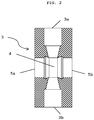
- Fig. 3a is a side view of the treatment unit (3) of the embodiment of the device (1) of the present invention according to Fig. 1 .
- Like reference numerals designate the same components as in Fig. 1 .
- a side face of the treatment unit (3) is shown in which there is provided an opening (5a) in the form of a blind bore.
- Said blind bore is tapered in a region adjacent to the treatment space (4, not shown here), i.e. it becomes smaller with increasing depth.
- a slit (6) In the inner face of the opening (5a), preferably in the center of the inner face, there is provided a slit (6).
- Fig. 3b is another schematic representation of the treatment unit (3) of the embodiment of the device (1) of the present invention according to Fig. 1 .
- Like reference numerals designate the same components as in Fig. 1 .
- the treatment unit (3) is turned by 90°.
- Fig. 3b the side faces of the treatment space (4) are shown that are not adjacent to the openings (5a, 5b). These side faces are curved. Here, they have a sinusoidal shape over their entire height.
Landscapes
- Life Sciences & Earth Sciences (AREA)
- Engineering & Computer Science (AREA)
- Health & Medical Sciences (AREA)
- Organic Chemistry (AREA)
- Wood Science & Technology (AREA)
- Chemical & Material Sciences (AREA)
- Bioinformatics & Cheminformatics (AREA)
- Zoology (AREA)
- Biotechnology (AREA)
- Genetics & Genomics (AREA)
- Biomedical Technology (AREA)
- Biochemistry (AREA)
- Microbiology (AREA)
- General Health & Medical Sciences (AREA)
- General Engineering & Computer Science (AREA)
- Cell Biology (AREA)
- Sustainable Development (AREA)
- Electromagnetism (AREA)
- Physics & Mathematics (AREA)
- Molecular Biology (AREA)
- Apparatus Associated With Microorganisms And Enzymes (AREA)
- Physical Deposition Of Substances That Are Components Of Semiconductor Devices (AREA)
- Apparatus For Disinfection Or Sterilisation (AREA)
- Immobilizing And Processing Of Enzymes And Microorganisms (AREA)
Priority Applications (9)
| Application Number | Priority Date | Filing Date | Title |
|---|---|---|---|
| EP20156009.1A EP3862420A1 (de) | 2020-02-07 | 2020-02-07 | Modifizierte behandlungskammer zur behandlung von zellen |
| PCT/EP2021/052674 WO2021156373A1 (en) | 2020-02-07 | 2021-02-04 | Modified treatment chamber for treating cells |
| CA3164514A CA3164514A1 (en) | 2020-02-07 | 2021-02-04 | Modified treatment chamber for treating cells |
| US17/797,866 US20230067450A1 (en) | 2020-02-07 | 2021-02-04 | Modified treatment chamber for treating cells |
| CN202180011790.1A CN115038781A (zh) | 2020-02-07 | 2021-02-04 | 用于处理细胞的改进的处理室 |
| KR1020227029346A KR20220131987A (ko) | 2020-02-07 | 2021-02-04 | 세포를 처리하기 위한 수정된 처리 챔버 |
| AU2021217469A AU2021217469B2 (en) | 2020-02-07 | 2021-02-04 | Modified treatment chamber for treating cells |
| IL295058A IL295058A (en) | 2020-02-07 | 2021-02-04 | A modified treatment cell for cell therapy |
| ZA2022/09727A ZA202209727B (en) | 2020-02-07 | 2022-08-31 | Modified treatment chamber for treating cells |
Applications Claiming Priority (1)
| Application Number | Priority Date | Filing Date | Title |
|---|---|---|---|
| EP20156009.1A EP3862420A1 (de) | 2020-02-07 | 2020-02-07 | Modifizierte behandlungskammer zur behandlung von zellen |
Publications (1)
| Publication Number | Publication Date |
|---|---|
| EP3862420A1 true EP3862420A1 (de) | 2021-08-11 |
Family
ID=69526143
Family Applications (1)
| Application Number | Title | Priority Date | Filing Date |
|---|---|---|---|
| EP20156009.1A Pending EP3862420A1 (de) | 2020-02-07 | 2020-02-07 | Modifizierte behandlungskammer zur behandlung von zellen |
Country Status (9)
| Country | Link |
|---|---|
| US (1) | US20230067450A1 (de) |
| EP (1) | EP3862420A1 (de) |
| KR (1) | KR20220131987A (de) |
| CN (1) | CN115038781A (de) |
| AU (1) | AU2021217469B2 (de) |
| CA (1) | CA3164514A1 (de) |
| IL (1) | IL295058A (de) |
| WO (1) | WO2021156373A1 (de) |
| ZA (1) | ZA202209727B (de) |
Citations (7)
| Publication number | Priority date | Publication date | Assignee | Title |
|---|---|---|---|---|
| DE10127247A1 (de) * | 2001-06-05 | 2002-12-19 | Eppendorf Ag | Vorrichtung und Verfahren zur elektrischen Behandlung suspendierter biologischer Partikel |
| US6749736B1 (en) * | 1998-06-26 | 2004-06-15 | Evotec Technologies Gmbh | Electrode arrangement for the dielectrophoretic diversion of particles |
| US20090155877A1 (en) * | 2004-07-06 | 2009-06-18 | Agency For Science Technology And Research | Biochip for sorting and lysing biological samples |
| US20110107655A1 (en) * | 2009-11-06 | 2011-05-12 | Michael Alan Kempkes | Pulsed electric field (PEF) method for continuous enhanced extraction of oil and lipids from small aquatic plants |
| KR20130129812A (ko) * | 2012-05-21 | 2013-11-29 | 한국과학기술원 | 세포 분쇄, 전기천공 및 활성도 분석 장치 및 방법 |
| EP2308969B1 (de) | 2009-09-29 | 2015-12-02 | Karlsruher Institut für Technologie | Verfahren zur Beschleunigung der Zellproliferation |
| CN110527624A (zh) * | 2018-05-24 | 2019-12-03 | 苏州壹达生物科技有限公司 | 一种间歇式流式电转染装置 |
-
2020
- 2020-02-07 EP EP20156009.1A patent/EP3862420A1/de active Pending
-
2021
- 2021-02-04 US US17/797,866 patent/US20230067450A1/en active Pending
- 2021-02-04 WO PCT/EP2021/052674 patent/WO2021156373A1/en active Application Filing
- 2021-02-04 AU AU2021217469A patent/AU2021217469B2/en active Active
- 2021-02-04 KR KR1020227029346A patent/KR20220131987A/ko unknown
- 2021-02-04 CN CN202180011790.1A patent/CN115038781A/zh active Pending
- 2021-02-04 CA CA3164514A patent/CA3164514A1/en active Pending
- 2021-02-04 IL IL295058A patent/IL295058A/en unknown
-
2022
- 2022-08-31 ZA ZA2022/09727A patent/ZA202209727B/en unknown
Patent Citations (7)
| Publication number | Priority date | Publication date | Assignee | Title |
|---|---|---|---|---|
| US6749736B1 (en) * | 1998-06-26 | 2004-06-15 | Evotec Technologies Gmbh | Electrode arrangement for the dielectrophoretic diversion of particles |
| DE10127247A1 (de) * | 2001-06-05 | 2002-12-19 | Eppendorf Ag | Vorrichtung und Verfahren zur elektrischen Behandlung suspendierter biologischer Partikel |
| US20090155877A1 (en) * | 2004-07-06 | 2009-06-18 | Agency For Science Technology And Research | Biochip for sorting and lysing biological samples |
| EP2308969B1 (de) | 2009-09-29 | 2015-12-02 | Karlsruher Institut für Technologie | Verfahren zur Beschleunigung der Zellproliferation |
| US20110107655A1 (en) * | 2009-11-06 | 2011-05-12 | Michael Alan Kempkes | Pulsed electric field (PEF) method for continuous enhanced extraction of oil and lipids from small aquatic plants |
| KR20130129812A (ko) * | 2012-05-21 | 2013-11-29 | 한국과학기술원 | 세포 분쇄, 전기천공 및 활성도 분석 장치 및 방법 |
| CN110527624A (zh) * | 2018-05-24 | 2019-12-03 | 苏州壹达生物科技有限公司 | 一种间歇式流式电转染装置 |
Non-Patent Citations (1)
| Title |
|---|
| BUCHMANN LMATHYS A: "Perspective on Pulsed Electric Field Treatment in the Bio-based Industry", FRONT. BIOENG. BIOTECHNOL., vol. 7, 2019, pages 265 |
Also Published As
| Publication number | Publication date |
|---|---|
| CA3164514A1 (en) | 2021-08-12 |
| AU2021217469A1 (en) | 2022-08-25 |
| AU2021217469B2 (en) | 2024-05-23 |
| IL295058A (en) | 2022-09-01 |
| KR20220131987A (ko) | 2022-09-29 |
| CN115038781A (zh) | 2022-09-09 |
| WO2021156373A1 (en) | 2021-08-12 |
| US20230067450A1 (en) | 2023-03-02 |
| ZA202209727B (en) | 2023-12-20 |
Similar Documents
| Publication | Publication Date | Title |
|---|---|---|
| Matsumoto et al. | Inactivation of microorganisms by pulsed high voltage application | |
| EP1085827A1 (de) | Impuls- elektrisches feld behandlungssystem | |
| EP3862420A1 (de) | Modifizierte behandlungskammer zur behandlung von zellen | |
| JPH0398565A (ja) | 液体状食品の殺菌法 | |
| EP3862419A1 (de) | Berührungslose vorrichtung zur behandlung von zellen | |
| EP3862418A1 (de) | Vorrichtung zur behandlung von zellen | |
| US11684018B2 (en) | Methods and apparatuses for cold plasma in agriculture | |
| US20230066697A1 (en) | Conductivity-adjusted device for treating cells | |
| EP4053260A1 (de) | Vorrichtung mit einem einsatz zur behandlung von zellmaterial | |
| US20240132871A1 (en) | Device with an insert for treating cell material | |
| JP7084116B2 (ja) | 透析器を滅菌する方法および装置 | |
| CA3196636A1 (en) | Device for treating cells in a bypass | |
| JP5797077B2 (ja) | キノコの栽培方法 | |
| WO2012127423A1 (en) | Method and apparatus for treating fluids containing biological pollutants with an electric field | |
| Alkhafaji | An Investigation on the Non Thermal Pasteurisation Using Pulsed Electric Fields | |
| RU2193856C2 (ru) | Способ и устройство для обработки жидкостей и текучих продуктов |
Legal Events
| Date | Code | Title | Description |
|---|---|---|---|
| PUAI | Public reference made under article 153(3) epc to a published international application that has entered the european phase |
Free format text: ORIGINAL CODE: 0009012 |
|
| STAA | Information on the status of an ep patent application or granted ep patent |
Free format text: STATUS: THE APPLICATION HAS BEEN PUBLISHED |
|
| AK | Designated contracting states |
Kind code of ref document: A1 Designated state(s): AL AT BE BG CH CY CZ DE DK EE ES FI FR GB GR HR HU IE IS IT LI LT LU LV MC MK MT NL NO PL PT RO RS SE SI SK SM TR |
|
| STAA | Information on the status of an ep patent application or granted ep patent |
Free format text: STATUS: REQUEST FOR EXAMINATION WAS MADE |
|
| 17P | Request for examination filed |
Effective date: 20220210 |
|
| RBV | Designated contracting states (corrected) |
Designated state(s): AL AT BE BG CH CY CZ DE DK EE ES FI FR GB GR HR HU IE IS IT LI LT LU LV MC MK MT NL NO PL PT RO RS SE SI SK SM TR |
|
| P01 | Opt-out of the competence of the unified patent court (upc) registered |
Effective date: 20230523 |