EP3862231A1 - Vehicle seat arrangement - Google Patents
Vehicle seat arrangement Download PDFInfo
- Publication number
- EP3862231A1 EP3862231A1 EP20156054.7A EP20156054A EP3862231A1 EP 3862231 A1 EP3862231 A1 EP 3862231A1 EP 20156054 A EP20156054 A EP 20156054A EP 3862231 A1 EP3862231 A1 EP 3862231A1
- Authority
- EP
- European Patent Office
- Prior art keywords
- backrest
- airbag
- tether
- arrangement
- seat
- Prior art date
- Legal status (The legal status is an assumption and is not a legal conclusion. Google has not performed a legal analysis and makes no representation as to the accuracy of the status listed.)
- Granted
Links
- 238000000605 extraction Methods 0.000 claims description 6
- 210000001015 abdomen Anatomy 0.000 description 5
- 210000000038 chest Anatomy 0.000 description 3
- 230000001419 dependent effect Effects 0.000 description 1
Images

Classifications
-
- B—PERFORMING OPERATIONS; TRANSPORTING
- B60—VEHICLES IN GENERAL
- B60R—VEHICLES, VEHICLE FITTINGS, OR VEHICLE PARTS, NOT OTHERWISE PROVIDED FOR
- B60R21/00—Arrangements or fittings on vehicles for protecting or preventing injuries to occupants or pedestrians in case of accidents or other traffic risks
- B60R21/02—Occupant safety arrangements or fittings, e.g. crash pads
- B60R21/16—Inflatable occupant restraints or confinements designed to inflate upon impact or impending impact, e.g. air bags
- B60R21/20—Arrangements for storing inflatable members in their non-use or deflated condition; Arrangement or mounting of air bag modules or components
- B60R21/207—Arrangements for storing inflatable members in their non-use or deflated condition; Arrangement or mounting of air bag modules or components in vehicle seats
-
- B—PERFORMING OPERATIONS; TRANSPORTING
- B60—VEHICLES IN GENERAL
- B60R—VEHICLES, VEHICLE FITTINGS, OR VEHICLE PARTS, NOT OTHERWISE PROVIDED FOR
- B60R21/00—Arrangements or fittings on vehicles for protecting or preventing injuries to occupants or pedestrians in case of accidents or other traffic risks
- B60R2021/0002—Type of accident
- B60R2021/0004—Frontal collision
-
- B—PERFORMING OPERATIONS; TRANSPORTING
- B60—VEHICLES IN GENERAL
- B60R—VEHICLES, VEHICLE FITTINGS, OR VEHICLE PARTS, NOT OTHERWISE PROVIDED FOR
- B60R21/00—Arrangements or fittings on vehicles for protecting or preventing injuries to occupants or pedestrians in case of accidents or other traffic risks
- B60R21/02—Occupant safety arrangements or fittings, e.g. crash pads
- B60R21/16—Inflatable occupant restraints or confinements designed to inflate upon impact or impending impact, e.g. air bags
- B60R21/23—Inflatable members
- B60R21/231—Inflatable members characterised by their shape, construction or spatial configuration
- B60R21/233—Inflatable members characterised by their shape, construction or spatial configuration comprising a plurality of individual compartments; comprising two or more bag-like members, one within the other
- B60R2021/23308—Inflatable members characterised by their shape, construction or spatial configuration comprising a plurality of individual compartments; comprising two or more bag-like members, one within the other the individual compartments defining the external shape of the bag
-
- B—PERFORMING OPERATIONS; TRANSPORTING
- B60—VEHICLES IN GENERAL
- B60R—VEHICLES, VEHICLE FITTINGS, OR VEHICLE PARTS, NOT OTHERWISE PROVIDED FOR
- B60R21/00—Arrangements or fittings on vehicles for protecting or preventing injuries to occupants or pedestrians in case of accidents or other traffic risks
- B60R21/02—Occupant safety arrangements or fittings, e.g. crash pads
- B60R21/16—Inflatable occupant restraints or confinements designed to inflate upon impact or impending impact, e.g. air bags
- B60R21/23—Inflatable members
- B60R21/231—Inflatable members characterised by their shape, construction or spatial configuration
- B60R21/2334—Expansion control features
- B60R21/2338—Tethers
- B60R2021/23386—External tether means
- B60R2021/23388—External tether means having ends which are movable or detachable during deployment
Definitions
- the present invention relates to a vehicle seat arrangement for a motor vehicle, with a backrest, a seat cushion, at least one airbag module, the airbag module being arranged in the backrest and the airbag module comprising at least one airbag, a tether mechanism for the airbag module, the tether mechanism comprising at least one tether arrangement, the tether arrangement being connected to the airbag and with at least one end to the backrest and/or seat cushion, and a seat belt arrangement, the seat belt arrangement comprising a seat belt, wherein in a fastened state a section of the seat belt extends diagonally from an upper location on a first side of the backrest towards a lower location on a second side of the backrest, the second side being opposite to the first side, wherein the airbag is shaped in such a way that in the deployed state a frontal section of the airbag is arranged directly in front of a central axis of the backrest.
- US 2017/0259774 A1 discloses a vehicle seat arrangement, in which airbag modules are arranged on both sides of the backrest, so that in the deployed state airbags are arranged laterally besides a occupant on both sides. While the disclosed airbag arrangement protects the occupant against lateral impact, the head of the occupant is to be protected with an additional airbag.
- KR 1020190126213 suggests that the airbag of the airbag module being arranged on the outboard side of the seat comprises a lateral section and a frontal section, wherein in the deployed state the lateral section is arranged laterally beside the occupant and the frontal section is arranged in front of the occupant, wherein the frontal section comprises an extension, which is arranged in front of the head of the occupant. Due to the diagonally extending seat belt extending from an upper location on the outboard side of the backrest to a lower location on the inboard side the thorax and/or the head of the occupant may be subject of great torsional forces during an accident.
- an object of the present invention to provide a vehicle seat arrangement and an airbag, with which the torsional forces acting on the body of an occupant during a crash may be lowered.
- the object is achieved by a vehicle seat arrangement as described above, wherein the first airbag module is arranged on the second side and therefore opposite to the side at which the seat belt arrangement is arranged in its unfastened state.
- the deployed airbag of the first airbag module and the thereto fixed tether arrangement can prevent greater torsional forces to the occupant towards the first side.
- an airbag which in the undeployed state is to be arranged in a backrest and comprises a lateral section and a frontal section, wherein in the deployed state the lateral section is arranged laterally beside an occupant on the seat arrangement and the frontal section is arranged in front of the occupant, wherein a side of the frontal section facing the backrest (and therefore the head/face of the occupant) comprises a recess for receiving the face of the occupant during an accident.
- the recess is in particular shaped in such a way, that a deepening in the deployed airbag is formed, in which the face of the occupant may be received, wherein the received face is at least on its lateral sides and more preferably also on the upper and lower sides bounded by the recess.
- the head received in the recess is prevented from rotational movements by the recess of the airbag, so that lower torsional forces are applied to the occupant.
- the chin of the occupant may be received in the recess, whereby rotational movement of the head of the occupant in the up/down direction is avoided.
- the recess may be formed by internal tethers, which connect the (back) side (layer) of the deployed airbag facing the occupant with the (front) side (layer) of the deployed airbag facing away from the occupant.
- the first side is the inboard side of the motor vehicle and the second side is the outboard side of the vehicle.
- the first airbag module is arranged on the outboard side of the vehicle, so that the airbag having the frontal section deploys between the occupant and the door of the vehicle with a lateral section, so that the airbag is supported by the door during an accident and during deployment.
- the inflation of the lateral section may also move the occupant towards first side (middle of the vehicle) into a more defined position.
- the seat belt arrangement in its unfastened state arranged at the inboard side of the seat and preferably within the backrest and/or seat cushion.
- a seat belt retractor preferably with a seat belt load limiter and/or with a seat belt tensioning device is arranged in the backrest, more preferably in an upper section of the backrest, preferably on the inboard side of the backrest.
- Such already known load limiters for the seat belt arrangement allow extraction of the seat belt during a crash with defined forces.
- Such a load limiter is usually integrated in the retractor of the seat belt arrangement, with which the seat belt is retracted during normal use.
- the buckle for the seat belt arrangement is preferably arranged on the second (in particular outboard) side.
- only the first airbag module is embodied on the second side and no further airbag module(s) is/are arranged on the vehicle seat arrangement. In particular no airbag module is arranged on the first side of the vehicle seat arrangement.
- the frontal section protects the passenger mainly during a frontal crash and the lateral section protects the passenger mainly during a side crash.
- the tether arrangement may be made of exactly one tether or alternatively of multiple tethers.
- the tether arrangement is connected to the airbag and with both ends to the backrest and/or the seat cushion, preferably with one end to the backrest and with the other end to the seat cushion. While it is principally sufficient, if there is one tether arrangement for an airbag, there might be two or three or even more tether arrangements for one airbag.
- a tether arrangement for the airbag of the first airbag module extends from (over) an upper side of the backrest over a shoulder of the occupant towards a lower section of the backrest or towards the seat cushion, while a middle part of the tether arrangement is connected fixedly or movably to the airbag.
- the middle section of a first tether arrangement is connected to the frontal section of the airbag of the first airbag module.
- the middle section of the tether arrangement is not connected to an outer side of the deployed airbag (facing away from the occupant) but to an inner side of the airbag facing towards the occupant in the deployed state.
- the airbag of the first airbag module might be connected to a (second) tether arrangement, which preferably also extends from/over an upper section of the backrest to the lower section of the backrest and/or to the seat cushion, wherein the middle section of the second tether arrangement is connected in particular movably to the lateral section of the airbag.
- a (second) tether arrangement which preferably also extends from/over an upper section of the backrest to the lower section of the backrest and/or to the seat cushion, wherein the middle section of the second tether arrangement is connected in particular movably to the lateral section of the airbag.
- One or both tether arrangement(s) can extend between two supports of a head rest of the backrest.
- Each tether mechanism may comprise a load limiter, a retractor and/or a tensioning device for one or each tether arrangement. While a retractor allows defined extraction and retraction of the tether arrangement, a tensioning device is embodied to tighten the tether arrangement at a specific time during an accident. Such a tensioning device may comprise a pyrotechnical element, with which a tether arrangement can be tightened. The tensioning device may be incorporated into the retractor or may act for example on an end of the tether arrangement directly.
- the retractor for the tether arrangement may comprise a load limiter, which allows extraction of the tether arrangement during an accident with predetermined forces.
- a seat load limiter may be arranged between the backrest and the seat cushion to absorb energy of a pivotable movement of the backrest relative to the seat cushion under external load.
- the frontal section of the airbag is in particular shaped in such a way, that it extends over at least 50%, preferably over at least 70% of the width of the backrest in the width direction, wherein in the deployed state the frontal section of the airbag extends in particular from the lateral section of the airbag at the second side over the central axis of the backrest. This way the head and shoulder part of the occupant is protected by the airbag.
- the frontal section of the deployed airbag only covers the head and the shoulder of an occupant and not the abdomen.
- a part of the lateral section of the airbag only covers the head and the shoulder of the occupant and not the abdomen. But, close to the second side of the backrest the lateral section of the airbag may also cover the abdomen section of the occupant.
- the airbag of the first airbag module comprises an extension at the first side of the frontal section which extends from the frontal section towards the backrest. Accordingly, in the deployed state the extension is arranged at the side of the head of the occupant opposite to the lateral section. This way a rotational movement of the head in particular in a lateral direction is avoided.
- the extension may be supported with a supporting tether arranged within the airbag and extending from the frontal section along the extension.
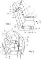
- the passenger seat arrangement depicted in figures 1 to 5 comprises a backrest 3 and a seat cushion 9, wherein an airbag module 10 is mounted in the outboard (second) side 16 of the backrest 3.
- An airbag 11 of the airbag module 10 is connected to a tether arrangement 6 of a tether mechanism 13.
- the tether mechanism 13 is connected to a tether retractor 17, which comprises a tether load limiter 18 and a tether tensioning device 19.
- the vehicle seat arrangement further comprises a seat belt arrangement 14 with a seat belt 4, which is arranged on the inboard (first) side 15 of the backrest 3 of the passenger seat facing a middle console 7.
- the seat belt 4 is connected to a seat belt retractor 20, which is arranged in an upper side of the backrest 3 on the first side 15.
- the seat belt retractor 20 comprises a seat belt load limiter 21 and a seat belt tensioning device 22.
- a seat load limiter 24 is arranged between the backrest 3 and the seat cushion 9, with which kinetic energy of a pivotal movement of the backrest 3 towards the seat cushion 9 can be absorbed in case of an accident.
- the airbag 11 inflates from the outboard second side 16 of the backrest 3 between an occupant 1 and a door 8 of the vehicle, so that the airbag 11 in its deployed state is arranged with a lateral section 12 between the occupant 1 and the door 8 and with a frontal section 5 in front of a head 2 of the occupant 1.
- the frontal section 5 of the airbag comprises a recess 23 (indicted in figure 1 with a circle) on the side facing the head 2 of the occupant 1.
- the lateral section 12 of the airbag 11 comprises in its deployed state a first section that covers the shoulder and abdomen of the occupant and a second section which is arranged in the height of the shoulder of the occupant 1 and which extends towards the frontal section 5.
- the frontal section 5 only covers the head 2 and the shoulder/chest area of the occupant and not the abdomen area.
- the tether arrangements 6 extend between two supports of a headrest of the backrest 3 towards the airbag 11.
- a first tether arrangement 6.1 is connected with one end to the airbag 11 close to the frontal section 5 and with its other end to the backrest 3, while a second tether arrangement 6.2 extends from the backrest 3 through the lateral section 12 of the airbag 11 towards the seat cushion 9.
- the seat belt 4 extends in its fastened state from an upper location on the first side 15 of the backrest 3 over the shoulder and chest of the occupant 1 towards a lower location on the second side 16 of the backrest 3 to a seat belt buckle 25 and from there over the lap of the occupant 1 towards a lower section on the first side 15 of the backrest 3.
- the seat belt arrangement 14 arranged on the inboard first side 15 of the backrest 3 avoids that during a crash the occupant 1 is subjected to torsional forces towards the door 8.
- the airbag 11 with the tether arrangements 6.1 and 6.2 arranged thereon avoids that the occupant 2 is subjected to torsional forces towards the middle console 7. Furthermore, due to the recess 23 in the frontal section 5 of the airbag 11 torsional forces on the head 2 of the occupant 1 can be reduced.
- the forces acting on the occupant 1 can be set in a known manner, while with the seat belt tensioning device 22 the seat belt 4 can be tensioned in a known manner.
- each tether arrangement 6.1 and 6.2 With the tether load limiter 18 connected to each tether arrangement the extraction of the tether arrangement 6.1 and 6.2 can be set to a predetermined value, while with the tether tensioning device 19 each tether arrangement 6.1, 6.2 can be tensioned individually or simultaneously.
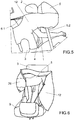
- the airbag 11 of the embodiment a vehicle arrangement of Fig. 6 differs from the before described embodiment in that the the airbag 11 comprises an extension 26 at the first side 15 of the frontal section 5 (and therefore opposite to the lateral section 12).
- the extension 26 In the deployed state the extension 26 extends from the frontal section 5 towards the backrest 3. Accordingly, the extension 26 is arranged at the side of the head 2 of the occupant 1 opposite to the lateral section 12. This way a rotational movement of the head 2 in particular in a lateral direction is avoided.
Abstract
Description
- The present invention relates to a vehicle seat arrangement for a motor vehicle, with a backrest, a seat cushion, at least one airbag module, the airbag module being arranged in the backrest and the airbag module comprising at least one airbag, a tether mechanism for the airbag module, the tether mechanism comprising at least one tether arrangement, the tether arrangement being connected to the airbag and with at least one end to the backrest and/or seat cushion, and a seat belt arrangement, the seat belt arrangement comprising a seat belt, wherein in a fastened state a section of the seat belt extends diagonally from an upper location on a first side of the backrest towards a lower location on a second side of the backrest, the second side being opposite to the first side, wherein the airbag is shaped in such a way that in the deployed state a frontal section of the airbag is arranged directly in front of a central axis of the backrest.
-
US 2017/0259774 A1 discloses a vehicle seat arrangement, in which airbag modules are arranged on both sides of the backrest, so that in the deployed state airbags are arranged laterally besides a occupant on both sides. While the disclosed airbag arrangement protects the occupant against lateral impact, the head of the occupant is to be protected with an additional airbag. - In view of this,
KR 1020190126213 - In view of this it is an object of the present invention to provide a vehicle seat arrangement and an airbag, with which the torsional forces acting on the body of an occupant during a crash may be lowered.
- This object is achieved with a vehicle seat arrangement and an airbag with the features of the respective independent claim. Further embodiments of the vehicle seat arrangement and the airbag are described in the dependent claims and in the description, wherein single features of the preferred embodiments can be combined with each other in a technical meaningful manner.
- In particular, the object is achieved by a vehicle seat arrangement as described above, wherein the first airbag module is arranged on the second side and therefore opposite to the side at which the seat belt arrangement is arranged in its unfastened state.
- While the seat belt arrangement prevents greater torsional forces of the occupant towards the second side, the deployed airbag of the first airbag module and the thereto fixed tether arrangement can prevent greater torsional forces to the occupant towards the first side.
- The object is also achieved with an airbag, which in the undeployed state is to be arranged in a backrest and comprises a lateral section and a frontal section, wherein in the deployed state the lateral section is arranged laterally beside an occupant on the seat arrangement and the frontal section is arranged in front of the occupant, wherein a side of the frontal section facing the backrest (and therefore the head/face of the occupant) comprises a recess for receiving the face of the occupant during an accident.
- The recess is in particular shaped in such a way, that a deepening in the deployed airbag is formed, in which the face of the occupant may be received, wherein the received face is at least on its lateral sides and more preferably also on the upper and lower sides bounded by the recess. This way, the head received in the recess is prevented from rotational movements by the recess of the airbag, so that lower torsional forces are applied to the occupant. In particular, the chin of the occupant may be received in the recess, whereby rotational movement of the head of the occupant in the up/down direction is avoided. The recess may be formed by internal tethers, which connect the (back) side (layer) of the deployed airbag facing the occupant with the (front) side (layer) of the deployed airbag facing away from the occupant.
- In a preferred embodiment of the vehicle seat arrangement the first side is the inboard side of the motor vehicle and the second side is the outboard side of the vehicle. Accordingly, the first airbag module is arranged on the outboard side of the vehicle, so that the airbag having the frontal section deploys between the occupant and the door of the vehicle with a lateral section, so that the airbag is supported by the door during an accident and during deployment. During deployment the inflation of the lateral section may also move the occupant towards first side (middle of the vehicle) into a more defined position. Furthermore, the seat belt arrangement in its unfastened state arranged at the inboard side of the seat and preferably within the backrest and/or seat cushion. In particular, a seat belt retractor, preferably with a seat belt load limiter and/or with a seat belt tensioning device is arranged in the backrest, more preferably in an upper section of the backrest, preferably on the inboard side of the backrest. Such already known load limiters for the seat belt arrangement allow extraction of the seat belt during a crash with defined forces. Such a load limiter is usually integrated in the retractor of the seat belt arrangement, with which the seat belt is retracted during normal use.
- Furthermore, the buckle for the seat belt arrangement is preferably arranged on the second (in particular outboard) side.
- In a preferred embodiment, only the first airbag module is embodied on the second side and no further airbag module(s) is/are arranged on the vehicle seat arrangement. In particular no airbag module is arranged on the first side of the vehicle seat arrangement.
- The frontal section protects the passenger mainly during a frontal crash and the lateral section protects the passenger mainly during a side crash.
- The tether arrangement may be made of exactly one tether or alternatively of multiple tethers. Preferably, the tether arrangement is connected to the airbag and with both ends to the backrest and/or the seat cushion, preferably with one end to the backrest and with the other end to the seat cushion. While it is principally sufficient, if there is one tether arrangement for an airbag, there might be two or three or even more tether arrangements for one airbag.
- In particular, in an deployed state of the airbag a tether arrangement for the airbag of the first airbag module extends from (over) an upper side of the backrest over a shoulder of the occupant towards a lower section of the backrest or towards the seat cushion, while a middle part of the tether arrangement is connected fixedly or movably to the airbag. In particular, the middle section of a first tether arrangement is connected to the frontal section of the airbag of the first airbag module. In a preferred embodiment, the middle section of the tether arrangement is not connected to an outer side of the deployed airbag (facing away from the occupant) but to an inner side of the airbag facing towards the occupant in the deployed state.
- Furthermore, the airbag of the first airbag module might be connected to a (second) tether arrangement, which preferably also extends from/over an upper section of the backrest to the lower section of the backrest and/or to the seat cushion, wherein the middle section of the second tether arrangement is connected in particular movably to the lateral section of the airbag.
- One or both tether arrangement(s) can extend between two supports of a head rest of the backrest.
- Each tether mechanism may comprise a load limiter, a retractor and/or a tensioning device for one or each tether arrangement. While a retractor allows defined extraction and retraction of the tether arrangement, a tensioning device is embodied to tighten the tether arrangement at a specific time during an accident. Such a tensioning device may comprise a pyrotechnical element, with which a tether arrangement can be tightened. The tensioning device may be incorporated into the retractor or may act for example on an end of the tether arrangement directly.
- Furthermore, the retractor for the tether arrangement may comprise a load limiter, which allows extraction of the tether arrangement during an accident with predetermined forces.
- In addition to providing load limiting means with the seat belt arrangement and/or the tether mechanism or alternative thereto, a seat load limiter may be arranged between the backrest and the seat cushion to absorb energy of a pivotable movement of the backrest relative to the seat cushion under external load.
- The frontal section of the airbag is in particular shaped in such a way, that it extends over at least 50%, preferably over at least 70% of the width of the backrest in the width direction, wherein in the deployed state the frontal section of the airbag extends in particular from the lateral section of the airbag at the second side over the central axis of the backrest. This way the head and shoulder part of the occupant is protected by the airbag.
- In a preferred embodiment, the frontal section of the deployed airbag only covers the head and the shoulder of an occupant and not the abdomen. In this regard, also a part of the lateral section of the airbag only covers the head and the shoulder of the occupant and not the abdomen. But, close to the second side of the backrest the lateral section of the airbag may also cover the abdomen section of the occupant.
- In a further embodiment the airbag of the first airbag module comprises an extension at the first side of the frontal section which extends from the frontal section towards the backrest. Accordingly, in the deployed state the extension is arranged at the side of the head of the occupant opposite to the lateral section. This way a rotational movement of the head in particular in a lateral direction is avoided. The extension may be supported with a supporting tether arranged within the airbag and extending from the frontal section along the extension.
- The invention and the technical background will now be described with regard to the figures. The figures show schematically
- Figure 1:
- a perspective view of a vehicle seat arrangement in the mounted state,
- Figure 2:
- a perspective back view on the vehicle seat arrangement in an deployed state of the airbag,
- Figure 3:
- a perspective front view of the vehicle seat arrangement in the deployed state of the airbag,
- Figure 4:
- a side view of the vehicle seat arrangement in the deployed state of the airbag,
- Figure 5:
- a side view from outside in the deployed state of the airbag and
- Figure 6:
- a further embodiment of a vehicle seat arrangement with a different airbag.
- The passenger seat arrangement depicted in
figures 1 to 5 comprises abackrest 3 and aseat cushion 9, wherein anairbag module 10 is mounted in the outboard (second)side 16 of thebackrest 3. Anairbag 11 of theairbag module 10 is connected to atether arrangement 6 of atether mechanism 13. - The
tether mechanism 13 is connected to atether retractor 17, which comprises atether load limiter 18 and atether tensioning device 19. - The vehicle seat arrangement further comprises a
seat belt arrangement 14 with aseat belt 4, which is arranged on the inboard (first)side 15 of thebackrest 3 of the passenger seat facing amiddle console 7. Theseat belt 4 is connected to aseat belt retractor 20, which is arranged in an upper side of thebackrest 3 on thefirst side 15. Theseat belt retractor 20 comprises a seatbelt load limiter 21 and a seatbelt tensioning device 22. - Furthermore, a
seat load limiter 24 is arranged between thebackrest 3 and theseat cushion 9, with which kinetic energy of a pivotal movement of thebackrest 3 towards theseat cushion 9 can be absorbed in case of an accident. - In case of an accident the
airbag 11 inflates from the outboardsecond side 16 of thebackrest 3 between anoccupant 1 and adoor 8 of the vehicle, so that theairbag 11 in its deployed state is arranged with alateral section 12 between theoccupant 1 and thedoor 8 and with afrontal section 5 in front of ahead 2 of theoccupant 1. - The
frontal section 5 of the airbag comprises a recess 23 (indicted infigure 1 with a circle) on the side facing thehead 2 of theoccupant 1. As can best seen infigure 5 , thelateral section 12 of theairbag 11 comprises in its deployed state a first section that covers the shoulder and abdomen of the occupant and a second section which is arranged in the height of the shoulder of theoccupant 1 and which extends towards thefrontal section 5. Thefrontal section 5 only covers thehead 2 and the shoulder/chest area of the occupant and not the abdomen area. - As can be best seen in
figures 1 and 2 thetether arrangements 6 extend between two supports of a headrest of thebackrest 3 towards theairbag 11. A first tether arrangement 6.1 is connected with one end to theairbag 11 close to thefrontal section 5 and with its other end to thebackrest 3, while a second tether arrangement 6.2 extends from thebackrest 3 through thelateral section 12 of theairbag 11 towards theseat cushion 9. - As depicted in
figures 2 to 5 theseat belt 4 extends in its fastened state from an upper location on thefirst side 15 of thebackrest 3 over the shoulder and chest of theoccupant 1 towards a lower location on thesecond side 16 of thebackrest 3 to aseat belt buckle 25 and from there over the lap of theoccupant 1 towards a lower section on thefirst side 15 of thebackrest 3. - The
seat belt arrangement 14 arranged on the inboardfirst side 15 of thebackrest 3 avoids that during a crash theoccupant 1 is subjected to torsional forces towards thedoor 8. On the other hand, theairbag 11 with the tether arrangements 6.1 and 6.2 arranged thereon avoids that theoccupant 2 is subjected to torsional forces towards themiddle console 7. Furthermore, due to therecess 23 in thefrontal section 5 of theairbag 11 torsional forces on thehead 2 of theoccupant 1 can be reduced. - With the seat
belt load limiter 21 the forces acting on theoccupant 1 can be set in a known manner, while with the seatbelt tensioning device 22 theseat belt 4 can be tensioned in a known manner. - With the
tether load limiter 18 connected to each tether arrangement the extraction of the tether arrangement 6.1 and 6.2 can be set to a predetermined value, while with thetether tensioning device 19 each tether arrangement 6.1, 6.2 can be tensioned individually or simultaneously. - The
airbag 11 of the embodiment a vehicle arrangement ofFig. 6 differs from the before described embodiment in that the theairbag 11 comprises anextension 26 at thefirst side 15 of the frontal section 5 (and therefore opposite to the lateral section 12). In the deployed state theextension 26 extends from thefrontal section 5 towards thebackrest 3. Accordingly, theextension 26 is arranged at the side of thehead 2 of theoccupant 1 opposite to thelateral section 12. This way a rotational movement of thehead 2 in particular in a lateral direction is avoided. -
- 1
- occupant
- 2
- head
- 3
- backrest
- 4
- seat belt
- 5
- frontal section
- 6
- tether arrangement
- 7
- middle console
- 8
- door
- 9
- seat cushion
- 10
- airbag module
- 11
- airbag
- 12
- lateral section
- 13
- tether mechanism
- 14
- seat belt arrangement
- 15
- first side
- 16
- second side
- 17
- tether retractor
- 18
- tether load limiter
- 19
- tether tensioning device
- 20
- seat belt retractor
- 21
- seat belt load limiter
- 22
- seat belt tensioning device
- 23
- recess
- 24
- seat load limiter
- 25
- seat belt buckle
- 26
- extension
Claims (15)
- Vehicle seat arrangement for a motor vehicle, with- a backrest (3),- a seat cushion (9),- at least one airbag module (10), the airbag module (10) being arranged in the backrest (3) and the airbag module (10) comprising at least one airbag (11),- a tether mechanism (13) for the airbag module (10), the tether mechanism (13) comprising at least one tether arrangement (6), the tether arrangement (6) being connected to the airbag (11) and with at least one end to the backrest (3) and/or seat cushion (9), and- a seat belt arrangement (14), the seat belt arrangement (14) comprising a seat belt (4), wherein in a fastened state a section of the seat belt (4) extends diagonally from an upper location on a first side (15) of the backrest (3) towards a lower location on a second side (16) of the backrest (3), the second side (16) being opposite to the first side (15), whereinan airbag (11) of a first airbag module (10) is shaped in such a way that in the deployed state a frontal section (5) of the airbag (11) is arranged directly in front of a central axis of the backrest (3),
characterized in that
the first airbag module (10) is arranged on the second side (16). - Vehicle seat arrangement according to claim 1, wherein the first side (15) is the inboard side of the motor vehicle and the second side (16) is the outboard side of the vehicle.
- Vehicle seat arrangement according to one of the preceding claims, wherein the tether mechanism (13) comprises a tether load limiter (18), which allows extraction of the tether arrangement (6).
- Vehicle seat arrangement according to one of the preceding claims, wherein the tether mechanism (13) comprises a tether retractor (17), which allows retraction of the tether arrangement (6).
- Vehicle seat arrangement according to one of the preceding claims, wherein the tether mechanism (13) comprises a tether tensioning device (19), which allows tensioning of the tether arrangement (6).
- Vehicle seat arrangement according to one of the preceding claims, wherein the seat belt arrangement (14) comprises a seat belt load limiter (21), which allows extraction of the seat belt (4).
- Vehicle seat arrangement according to one of the preceding claims, wherein a side of the frontal section (5) facing the backrest (3) comprises a recess (23) for receiving the face of an occupant (1) during an accident.
- Vehicle seat arrangement according to one of the preceding claims, wherein in the deployed state the frontal section (5) of the airbag extends from the second side (16) over the central axis of the backrest (3) toward the first side (15).
- Vehicle seat arrangement according to claim, wherein in the deployed state the frontal section (5) covers at least 50 % of the width of the backrest (3) in the width direction.
- Vehicle seat arrangement according to one of the preceding claims, wherein the airbag (11) comprises an extension (26) at the first side (15) of the frontal section (5) which extends from the frontal section (5) towards the backrest (3).
- Vehicle seat arrangement according to one of the preceding claims, wherein the seat belt arrangement (14) is integrated in the backrest (3) and/or the seat cushion (9).
- Vehicle seat arrangement according to one of the preceding claims, wherein the backrest (3) is pivotable relative to the seat cushion (9) under external load and wherein a seat load limiter (24) is arranged between the backrest (3) and the seat cushion (9) to absorb energy of the pivotal movement.
- Vehicle seat arrangement according to one of the preceding claims, wherein each tether arrangement (6) is made of exactly one tether or multiple tethers.
- Vehicle seat arrangement according to one of the preceding claims, wherein the tether arrangement (6) is connected to the airbag (11) and with both ends to the backrest (3) and/or seat cushion (9), preferably with one end to the backrest (3) and with the other end to the seat cushion (9).
- Airbag for a vehicle seat arrangement, in particular for a vehicle arrangement according to one of the preceding claims, to be arranged in a backrest (3) and comprising a lateral section (12) and a frontal section (5), wherein in the deployed state the lateral section (12) is arranged laterally beside an occupant (1) and the frontal section (5) is arranged in front of the occupant (1), wherein a recess (23) for receiving the face of the occupant (1) during an accident is embodied on a side of the frontal section (5) facing the backrest (3).
Priority Applications (1)
| Application Number | Priority Date | Filing Date | Title |
|---|---|---|---|
| EP20156054.7A EP3862231B1 (en) | 2020-02-07 | 2020-02-07 | Vehicle seat arrangement |
Applications Claiming Priority (1)
| Application Number | Priority Date | Filing Date | Title |
|---|---|---|---|
| EP20156054.7A EP3862231B1 (en) | 2020-02-07 | 2020-02-07 | Vehicle seat arrangement |
Publications (2)
| Publication Number | Publication Date |
|---|---|
| EP3862231A1 true EP3862231A1 (en) | 2021-08-11 |
| EP3862231B1 EP3862231B1 (en) | 2023-01-04 |
Family
ID=69526174
Family Applications (1)
| Application Number | Title | Priority Date | Filing Date |
|---|---|---|---|
| EP20156054.7A Active EP3862231B1 (en) | 2020-02-07 | 2020-02-07 | Vehicle seat arrangement |
Country Status (1)
| Country | Link |
|---|---|
| EP (1) | EP3862231B1 (en) |
Cited By (3)
| Publication number | Priority date | Publication date | Assignee | Title |
|---|---|---|---|---|
| WO2023160859A1 (en) * | 2022-02-24 | 2023-08-31 | Autoliv Development Ab | Restraining device, restraining assembly and seat unit |
| DE102022106752A1 (en) | 2022-03-23 | 2023-09-28 | Audi Aktiengesellschaft | Vehicle seat |
| US20230406258A1 (en) * | 2022-06-21 | 2023-12-21 | Ford Global Technologies, Llc | Seat assembly with deployable belt member |
Citations (6)
| Publication number | Priority date | Publication date | Assignee | Title |
|---|---|---|---|---|
| US20170259774A1 (en) | 2014-09-08 | 2017-09-14 | Tetsuya Matsushita | Vehicle Occupant Restraint Device |
| US20180326938A1 (en) * | 2017-05-09 | 2018-11-15 | Autoliv Asp, Inc. | Oblique impact airbag mitts and related systems and methods |
| US20190061675A1 (en) * | 2017-08-24 | 2019-02-28 | Hyundai Motor Compnay | Side airbag device for a vehicle |
| DE102017131140A1 (en) * | 2017-12-22 | 2019-06-27 | Trw Automotive Gmbh | A vehicle occupant protection system and method for operating a vehicle occupant protection system |
| JP2019147426A (en) * | 2018-02-26 | 2019-09-05 | トヨタ自動車株式会社 | Vehicle occupant protection device |
| KR20190126213A (en) | 2018-05-01 | 2019-11-11 | 아우토리브 디벨롭먼트 아베 | Airbag apparatus of vehicle |
-
2020
- 2020-02-07 EP EP20156054.7A patent/EP3862231B1/en active Active
Patent Citations (6)
| Publication number | Priority date | Publication date | Assignee | Title |
|---|---|---|---|---|
| US20170259774A1 (en) | 2014-09-08 | 2017-09-14 | Tetsuya Matsushita | Vehicle Occupant Restraint Device |
| US20180326938A1 (en) * | 2017-05-09 | 2018-11-15 | Autoliv Asp, Inc. | Oblique impact airbag mitts and related systems and methods |
| US20190061675A1 (en) * | 2017-08-24 | 2019-02-28 | Hyundai Motor Compnay | Side airbag device for a vehicle |
| DE102017131140A1 (en) * | 2017-12-22 | 2019-06-27 | Trw Automotive Gmbh | A vehicle occupant protection system and method for operating a vehicle occupant protection system |
| JP2019147426A (en) * | 2018-02-26 | 2019-09-05 | トヨタ自動車株式会社 | Vehicle occupant protection device |
| KR20190126213A (en) | 2018-05-01 | 2019-11-11 | 아우토리브 디벨롭먼트 아베 | Airbag apparatus of vehicle |
Cited By (4)
| Publication number | Priority date | Publication date | Assignee | Title |
|---|---|---|---|---|
| WO2023160859A1 (en) * | 2022-02-24 | 2023-08-31 | Autoliv Development Ab | Restraining device, restraining assembly and seat unit |
| DE102022106752A1 (en) | 2022-03-23 | 2023-09-28 | Audi Aktiengesellschaft | Vehicle seat |
| US20230406258A1 (en) * | 2022-06-21 | 2023-12-21 | Ford Global Technologies, Llc | Seat assembly with deployable belt member |
| US11904795B2 (en) * | 2022-06-21 | 2024-02-20 | Ford Global Technologies, Llc | Seat assembly with deployable belt member |
Also Published As
| Publication number | Publication date |
|---|---|
| EP3862231B1 (en) | 2023-01-04 |
Similar Documents
| Publication | Publication Date | Title |
|---|---|---|
| EP3529110B1 (en) | Air bag device and vehicle seat provided with an air bag device | |
| CN109421650B (en) | Airbag for a vehicle and associated vehicle | |
| EP3862231A1 (en) | Vehicle seat arrangement | |
| EP1615805B1 (en) | An airbag arrangement | |
| US20050236819A1 (en) | Safety device | |
| US10870408B2 (en) | Airbag device for a motor vehicle, and airbag cushion for an airbag device | |
| CN111094077B (en) | Airbag module for a vehicle seat of a motor vehicle | |
| EP2799290B1 (en) | Head restraint system | |
| CN111301332B (en) | Safety device for vehicle | |
| US8282126B2 (en) | Occupant restraint system | |
| US8388019B2 (en) | Airbag module | |
| US11292419B2 (en) | Airbag module | |
| WO2017177236A1 (en) | Rear seat airbag module | |
| JP2005306377A5 (en) | ||
| US20130106079A1 (en) | Airbag arrangement for bulkhead seats | |
| US7219957B1 (en) | Vehicle seat with articulating cushion component | |
| US20230311806A1 (en) | Airbag arrangement | |
| US6302436B1 (en) | Protection system against lateral collisions for vehicle occupants | |
| US10308205B2 (en) | Safety restraint system with an airbag having an inflatable pelvis restraint portion and related method | |
| US10787145B2 (en) | Airbag device for a motor vehicle, and airbag cushion for an airbag device | |
| US20070235999A1 (en) | Vehicle seat belt apparatus | |
| US7806440B2 (en) | Dual spool retractor in belt-in-seat | |
| US20040212185A1 (en) | Compact tethering system and method for an inflatabe curtain | |
| DE10047808B4 (en) | Safety device on a seat back of a vehicle seat, in particular a motor vehicle seat | |
| CN219236973U (en) | A first chest gasbag protection system for vehicle seat |
Legal Events
| Date | Code | Title | Description |
|---|---|---|---|
| PUAI | Public reference made under article 153(3) epc to a published international application that has entered the european phase |
Free format text: ORIGINAL CODE: 0009012 |
|
| STAA | Information on the status of an ep patent application or granted ep patent |
Free format text: STATUS: THE APPLICATION HAS BEEN PUBLISHED |
|
| AK | Designated contracting states |
Kind code of ref document: A1 Designated state(s): AL AT BE BG CH CY CZ DE DK EE ES FI FR GB GR HR HU IE IS IT LI LT LU LV MC MK MT NL NO PL PT RO RS SE SI SK SM TR |
|
| STAA | Information on the status of an ep patent application or granted ep patent |
Free format text: STATUS: REQUEST FOR EXAMINATION WAS MADE |
|
| 17P | Request for examination filed |
Effective date: 20220208 |
|
| RBV | Designated contracting states (corrected) |
Designated state(s): AL AT BE BG CH CY CZ DE DK EE ES FI FR GB GR HR HU IE IS IT LI LT LU LV MC MK MT NL NO PL PT RO RS SE SI SK SM TR |
|
| RIC1 | Information provided on ipc code assigned before grant |
Ipc: B60R 21/207 20060101AFI20220503BHEP |
|
| GRAP | Despatch of communication of intention to grant a patent |
Free format text: ORIGINAL CODE: EPIDOSNIGR1 |
|
| STAA | Information on the status of an ep patent application or granted ep patent |
Free format text: STATUS: GRANT OF PATENT IS INTENDED |
|
| INTG | Intention to grant announced |
Effective date: 20220831 |
|
| GRAS | Grant fee paid |
Free format text: ORIGINAL CODE: EPIDOSNIGR3 |
|
| GRAA | (expected) grant |
Free format text: ORIGINAL CODE: 0009210 |
|
| STAA | Information on the status of an ep patent application or granted ep patent |
Free format text: STATUS: THE PATENT HAS BEEN GRANTED |
|
| AK | Designated contracting states |
Kind code of ref document: B1 Designated state(s): AL AT BE BG CH CY CZ DE DK EE ES FI FR GB GR HR HU IE IS IT LI LT LU LV MC MK MT NL NO PL PT RO RS SE SI SK SM TR |
|
| REG | Reference to a national code |
Ref country code: GB Ref legal event code: FG4D |
|
| REG | Reference to a national code |
Ref country code: CH Ref legal event code: EP |
|
| REG | Reference to a national code |
Ref country code: AT Ref legal event code: REF Ref document number: 1541730 Country of ref document: AT Kind code of ref document: T Effective date: 20230115 |
|
| REG | Reference to a national code |
Ref country code: DE Ref legal event code: R096 Ref document number: 602020007269 Country of ref document: DE |
|
| REG | Reference to a national code |
Ref country code: IE Ref legal event code: FG4D |
|
| REG | Reference to a national code |
Ref country code: LT Ref legal event code: MG9D |
|
| PGFP | Annual fee paid to national office [announced via postgrant information from national office to epo] |
Ref country code: FR Payment date: 20230216 Year of fee payment: 4 |
|
| REG | Reference to a national code |
Ref country code: NL Ref legal event code: MP Effective date: 20230104 |
|
| REG | Reference to a national code |
Ref country code: AT Ref legal event code: MK05 Ref document number: 1541730 Country of ref document: AT Kind code of ref document: T Effective date: 20230104 |
|
| P01 | Opt-out of the competence of the unified patent court (upc) registered |
Effective date: 20230512 |
|
| PG25 | Lapsed in a contracting state [announced via postgrant information from national office to epo] |
Ref country code: NL Free format text: LAPSE BECAUSE OF FAILURE TO SUBMIT A TRANSLATION OF THE DESCRIPTION OR TO PAY THE FEE WITHIN THE PRESCRIBED TIME-LIMIT Effective date: 20230104 |
|
| PG25 | Lapsed in a contracting state [announced via postgrant information from national office to epo] |
Ref country code: RS Free format text: LAPSE BECAUSE OF FAILURE TO SUBMIT A TRANSLATION OF THE DESCRIPTION OR TO PAY THE FEE WITHIN THE PRESCRIBED TIME-LIMIT Effective date: 20230104 Ref country code: PT Free format text: LAPSE BECAUSE OF FAILURE TO SUBMIT A TRANSLATION OF THE DESCRIPTION OR TO PAY THE FEE WITHIN THE PRESCRIBED TIME-LIMIT Effective date: 20230504 Ref country code: NO Free format text: LAPSE BECAUSE OF FAILURE TO SUBMIT A TRANSLATION OF THE DESCRIPTION OR TO PAY THE FEE WITHIN THE PRESCRIBED TIME-LIMIT Effective date: 20230404 Ref country code: LV Free format text: LAPSE BECAUSE OF FAILURE TO SUBMIT A TRANSLATION OF THE DESCRIPTION OR TO PAY THE FEE WITHIN THE PRESCRIBED TIME-LIMIT Effective date: 20230104 Ref country code: LT Free format text: LAPSE BECAUSE OF FAILURE TO SUBMIT A TRANSLATION OF THE DESCRIPTION OR TO PAY THE FEE WITHIN THE PRESCRIBED TIME-LIMIT Effective date: 20230104 Ref country code: HR Free format text: LAPSE BECAUSE OF FAILURE TO SUBMIT A TRANSLATION OF THE DESCRIPTION OR TO PAY THE FEE WITHIN THE PRESCRIBED TIME-LIMIT Effective date: 20230104 Ref country code: ES Free format text: LAPSE BECAUSE OF FAILURE TO SUBMIT A TRANSLATION OF THE DESCRIPTION OR TO PAY THE FEE WITHIN THE PRESCRIBED TIME-LIMIT Effective date: 20230104 Ref country code: AT Free format text: LAPSE BECAUSE OF FAILURE TO SUBMIT A TRANSLATION OF THE DESCRIPTION OR TO PAY THE FEE WITHIN THE PRESCRIBED TIME-LIMIT Effective date: 20230104 |
|
| PG25 | Lapsed in a contracting state [announced via postgrant information from national office to epo] |
Ref country code: SE Free format text: LAPSE BECAUSE OF FAILURE TO SUBMIT A TRANSLATION OF THE DESCRIPTION OR TO PAY THE FEE WITHIN THE PRESCRIBED TIME-LIMIT Effective date: 20230104 Ref country code: PL Free format text: LAPSE BECAUSE OF FAILURE TO SUBMIT A TRANSLATION OF THE DESCRIPTION OR TO PAY THE FEE WITHIN THE PRESCRIBED TIME-LIMIT Effective date: 20230104 Ref country code: IS Free format text: LAPSE BECAUSE OF FAILURE TO SUBMIT A TRANSLATION OF THE DESCRIPTION OR TO PAY THE FEE WITHIN THE PRESCRIBED TIME-LIMIT Effective date: 20230504 Ref country code: GR Free format text: LAPSE BECAUSE OF FAILURE TO SUBMIT A TRANSLATION OF THE DESCRIPTION OR TO PAY THE FEE WITHIN THE PRESCRIBED TIME-LIMIT Effective date: 20230405 Ref country code: FI Free format text: LAPSE BECAUSE OF FAILURE TO SUBMIT A TRANSLATION OF THE DESCRIPTION OR TO PAY THE FEE WITHIN THE PRESCRIBED TIME-LIMIT Effective date: 20230104 |
|
| REG | Reference to a national code |
Ref country code: CH Ref legal event code: PL |
|
| P02 | Opt-out of the competence of the unified patent court (upc) changed |
Effective date: 20230830 |
|
| REG | Reference to a national code |
Ref country code: DE Ref legal event code: R097 Ref document number: 602020007269 Country of ref document: DE |
|
| REG | Reference to a national code |
Ref country code: BE Ref legal event code: MM Effective date: 20230228 |
|
| PG25 | Lapsed in a contracting state [announced via postgrant information from national office to epo] |
Ref country code: SM Free format text: LAPSE BECAUSE OF FAILURE TO SUBMIT A TRANSLATION OF THE DESCRIPTION OR TO PAY THE FEE WITHIN THE PRESCRIBED TIME-LIMIT Effective date: 20230104 Ref country code: RO Free format text: LAPSE BECAUSE OF FAILURE TO SUBMIT A TRANSLATION OF THE DESCRIPTION OR TO PAY THE FEE WITHIN THE PRESCRIBED TIME-LIMIT Effective date: 20230104 Ref country code: MC Free format text: LAPSE BECAUSE OF FAILURE TO SUBMIT A TRANSLATION OF THE DESCRIPTION OR TO PAY THE FEE WITHIN THE PRESCRIBED TIME-LIMIT Effective date: 20230104 Ref country code: LU Free format text: LAPSE BECAUSE OF NON-PAYMENT OF DUE FEES Effective date: 20230207 Ref country code: LI Free format text: LAPSE BECAUSE OF NON-PAYMENT OF DUE FEES Effective date: 20230228 Ref country code: EE Free format text: LAPSE BECAUSE OF FAILURE TO SUBMIT A TRANSLATION OF THE DESCRIPTION OR TO PAY THE FEE WITHIN THE PRESCRIBED TIME-LIMIT Effective date: 20230104 Ref country code: DK Free format text: LAPSE BECAUSE OF FAILURE TO SUBMIT A TRANSLATION OF THE DESCRIPTION OR TO PAY THE FEE WITHIN THE PRESCRIBED TIME-LIMIT Effective date: 20230104 Ref country code: CZ Free format text: LAPSE BECAUSE OF FAILURE TO SUBMIT A TRANSLATION OF THE DESCRIPTION OR TO PAY THE FEE WITHIN THE PRESCRIBED TIME-LIMIT Effective date: 20230104 Ref country code: CH Free format text: LAPSE BECAUSE OF NON-PAYMENT OF DUE FEES Effective date: 20230228 |
|
| PLBE | No opposition filed within time limit |
Free format text: ORIGINAL CODE: 0009261 |
|
| STAA | Information on the status of an ep patent application or granted ep patent |
Free format text: STATUS: NO OPPOSITION FILED WITHIN TIME LIMIT |
|
| PG25 | Lapsed in a contracting state [announced via postgrant information from national office to epo] |
Ref country code: SK Free format text: LAPSE BECAUSE OF FAILURE TO SUBMIT A TRANSLATION OF THE DESCRIPTION OR TO PAY THE FEE WITHIN THE PRESCRIBED TIME-LIMIT Effective date: 20230104 |
|
| 26N | No opposition filed |
Effective date: 20231005 |
|
| REG | Reference to a national code |
Ref country code: IE Ref legal event code: MM4A |
|
| PG25 | Lapsed in a contracting state [announced via postgrant information from national office to epo] |
Ref country code: SI Free format text: LAPSE BECAUSE OF FAILURE TO SUBMIT A TRANSLATION OF THE DESCRIPTION OR TO PAY THE FEE WITHIN THE PRESCRIBED TIME-LIMIT Effective date: 20230104 Ref country code: IE Free format text: LAPSE BECAUSE OF NON-PAYMENT OF DUE FEES Effective date: 20230207 |
|
| PG25 | Lapsed in a contracting state [announced via postgrant information from national office to epo] |
Ref country code: BE Free format text: LAPSE BECAUSE OF NON-PAYMENT OF DUE FEES Effective date: 20230228 |
|
| PGFP | Annual fee paid to national office [announced via postgrant information from national office to epo] |
Ref country code: DE Payment date: 20240216 Year of fee payment: 5 Ref country code: GB Payment date: 20240222 Year of fee payment: 5 Ref country code: GB Payment date: 20240222 Year of fee payment: 4 |