EP3862056A1 - System and method for counting spatially arranged, moving markers - Google Patents
System and method for counting spatially arranged, moving markers Download PDFInfo
- Publication number
- EP3862056A1 EP3862056A1 EP20461509.0A EP20461509A EP3862056A1 EP 3862056 A1 EP3862056 A1 EP 3862056A1 EP 20461509 A EP20461509 A EP 20461509A EP 3862056 A1 EP3862056 A1 EP 3862056A1
- Authority
- EP
- European Patent Office
- Prior art keywords
- markers
- sensor
- sensors
- movement
- axis
- Prior art date
- Legal status (The legal status is an assumption and is not a legal conclusion. Google has not performed a legal analysis and makes no representation as to the accuracy of the status listed.)
- Granted
Links
Images




Classifications
-
- G—PHYSICS
- G06—COMPUTING OR CALCULATING; COUNTING
- G06D—DIGITAL FLUID-PRESSURE COMPUTING DEVICES
- G06D3/00—Computing devices characterised by the interrelationship of the functional units and having at least one moving part
-
- G—PHYSICS
- G06—COMPUTING OR CALCULATING; COUNTING
- G06C—DIGITAL COMPUTERS IN WHICH ALL THE COMPUTATION IS EFFECTED MECHANICALLY
- G06C15/00—Computing mechanisms; Actuating devices therefor
- G06C15/04—Adding or subtracting devices
-
- A—HUMAN NECESSITIES
- A63—SPORTS; GAMES; AMUSEMENTS
- A63B—APPARATUS FOR PHYSICAL TRAINING, GYMNASTICS, SWIMMING, CLIMBING, OR FENCING; BALL GAMES; TRAINING EQUIPMENT
- A63B21/00—Exercising apparatus for developing or strengthening the muscles or joints of the body by working against a counterforce, with or without measuring devices
- A63B21/06—User-manipulated weights
- A63B21/062—User-manipulated weights including guide for vertical or non-vertical weights or array of weights to move against gravity forces
- A63B21/0626—User-manipulated weights including guide for vertical or non-vertical weights or array of weights to move against gravity forces with substantially vertical guiding means
- A63B21/0628—User-manipulated weights including guide for vertical or non-vertical weights or array of weights to move against gravity forces with substantially vertical guiding means for vertical array of weights
-
- A—HUMAN NECESSITIES
- A63—SPORTS; GAMES; AMUSEMENTS
- A63B—APPARATUS FOR PHYSICAL TRAINING, GYMNASTICS, SWIMMING, CLIMBING, OR FENCING; BALL GAMES; TRAINING EQUIPMENT
- A63B2220/00—Measuring of physical parameters relating to sporting activity
- A63B2220/10—Positions
- A63B2220/13—Relative positions
-
- A—HUMAN NECESSITIES
- A63—SPORTS; GAMES; AMUSEMENTS
- A63B—APPARATUS FOR PHYSICAL TRAINING, GYMNASTICS, SWIMMING, CLIMBING, OR FENCING; BALL GAMES; TRAINING EQUIPMENT
- A63B2225/00—Miscellaneous features of sport apparatus, devices or equipment
- A63B2225/15—Miscellaneous features of sport apparatus, devices or equipment with identification means that can be read by electronic means
-
- A—HUMAN NECESSITIES
- A63—SPORTS; GAMES; AMUSEMENTS
- A63B—APPARATUS FOR PHYSICAL TRAINING, GYMNASTICS, SWIMMING, CLIMBING, OR FENCING; BALL GAMES; TRAINING EQUIPMENT
- A63B2225/00—Miscellaneous features of sport apparatus, devices or equipment
- A63B2225/20—Miscellaneous features of sport apparatus, devices or equipment with means for remote communication, e.g. internet or the like
-
- A—HUMAN NECESSITIES
- A63—SPORTS; GAMES; AMUSEMENTS
- A63B—APPARATUS FOR PHYSICAL TRAINING, GYMNASTICS, SWIMMING, CLIMBING, OR FENCING; BALL GAMES; TRAINING EQUIPMENT
- A63B2225/00—Miscellaneous features of sport apparatus, devices or equipment
- A63B2225/50—Wireless data transmission, e.g. by radio transmitters or telemetry
- A63B2225/54—Transponders, e.g. RFID
Definitions
- the present invention relates to a system and method for counting spatially arranged, moving markers positioned on corresponding objects.
- the present invention relates to a system for counting markers, present in a moving group, by sensors for detecting weight of at least one weight stack plate moved in a given weightlifting machine.
- US 20070213183 A1 discloses a linear array of sensors.
- the array of sensors includes a plurality of sensors positioned adjacent and opposite the resting position of each weight plate, and at equally spaced locations above the example stack of weights up to the highest travel position attainable by the top weight plate of the example stack of weights.
- the example sensor array is enclosed in, covered and/or attached to any variety of housing and/or mounting bracket.
- a drawback of this solution is that there must be present a lot of sensors wherein the number of sensors greatly exceeds the number of weight plates because the sensors must extend up to the highest travel position attainable by the top weight plate.
- EP3542874 entitled “System and method for assisting a weightlifting workout” describes a system where distances between the sensors are set during mounting and setup and are fixed for a given weight stack device. Nevertheless, these distances are a multiplication of a height of a single weight plate, for example four weight plates distance equals 10 cm for a weight plate having 2,5 cm height.
- a disadvantage of this solution is that it cannot immediately detect a moved weight because a weight stack must be moved (typically lifted) by a distance (typically height) equal to a spread of sensors so that one may determine how many markers (weight plates) have been moved.
- Such system is also not suitable to support weight stacks having weight plates of different sizes (e.g. weight plates of increasing height).
- the aim of the development of the present invention is therefore an improved and cost effective system and method counting spatially arranged, moving markers.
- An object of the present invention is a method for counting spatially arranged, moving markers wherein said markers are arranged to move along a movement axis being parallel to a sensors axis of sensors configured to detect said markers during movement, whereas there are fewer sensors than markers, the method being characterized in that it comprises the steps of: providing information on a number of markers; providing information on a sequence of said sensors; providing information on an initial setup of the system by specifying how many markers are preceding and following each sensor taking into account the axis of movement and a direction of an engaging movement; arranging said sensors, in said initial setup, such that at least two of the sensors are arranged such that all the markers precede them taking into account the axis of movement and said direction of the engaging movement; determining a sensor S T having 0 following markers and a sensor S T-1 following the S T sensor in the direction of the engaging movement; awaiting detection of a marker by the sensor S T-1 ; determining a sensor S B closest to the starting sensor taking into account said direction of an engaging movement and at the same time
- the method further comprises the steps of: in the case the verifying step is positive, setting a variable H as a sum of predefined heights of objects associated with said markers preceding the starting sensor based on the number of markers preceding the starting sensor as well as the number of markers counted by the starting sensor; determining a sensor S TT as the closest sensor following S T - H; and awaiting detection of a marker by the sensor S TT .
- said number of moved markers is increased by 1 when the S B is facing a marker.
- said information on an initial setup of the system comprises a list defining heights of all objects associated with said markers.
- said information on an initial setup of the system comprises a list defining weights of all objects associated with said markers whereas after said verifying step the method is configured to provide a total weight as a sum of weight of all objects associated with said moved markers.
- the method further comprises a step of awaiting a return of the weight plates to the initial position and increasing a counter of repetitions.
- said information on an initial setup of the system further comprises information on whether each sensor is facing a marker.
- said sensors are mounted on at least one rail being configured to be connectable to other such rails in order to form longer rails along said sensors axis.
- Another object of the present invention is a computer program comprising program code means for performing all the steps of the computer-implemented method according to the present invention when said program is run on a computer.
- Another object of the present invention is a computer readable medium storing computer-executable instructions performing all the steps of the computer-implemented method according to the present invention when executed on a computer.
- Another object of the present invention is a system for counting spatially arranged, moving markers wherein said markers are arranged to move along a movement axis being parallel to a sensors axis of sensors configured to detect said markers during movement, whereas there are fewer sensors than markers, the system being characterized in that: a configuration stored in a memory comprises: information on a number of markers; information on a sequence of said sensors; information on an initial setup of the system by specifying how many markers are preceding and following each sensor taking into account the axis of movement and a direction of an engaging movement; at least two of the sensors are arranged in said initial setup, such that all the markers precede them taking into account the axis of movement and the direction of the engaging movement; a controller configured to execute the steps of: determining a sensor S T having 0 following markers and a sensor S T-1 following the S T sensor in the direction of the engaging movement; awaiting detection of a marker by the sensor S T-1 ; determining a sensor S B closest to the starting sensor taking into account said direction of an engaging movement
- one of said sensors is arranged facing or preceding a first marker being the starting marker in said spatially arranged group of markers taking into account a direction of an engaging movement.
- said sensors are arranged on at least two connected rails arranged along the sensors axis wherein each rail is configured to provide a report to the controller wherein such report comprises sensors identifiers and sensors sequence.
- said controller is physically separated from said rails.
- said controller is further configured to execute the steps of: in the case the verifying step is positive, setting a variable H as a sum of predefined heights of objects associated with said markers preceding the starting sensor based on the number of markers preceding the starting sensor as well as the number of markers counted by the starting sensor; determining a sensor S TT as the closest sensor following position S T - H; and awaiting detection of a marker by the sensor S TT .
- these quantities take the form of electrical or magnetic signals capable of being stored, transferred, combined, compared, and otherwise manipulated in a computer system.
- these signals are referred to as bits, packets, messages, values, elements, symbols, characters, terms, numbers, or the like.
- a computer-readable (storage) medium typically may be non-transitory and/or comprise a non-transitory device.
- a non-transitory storage medium may include a device that may be tangible, meaning that the device has a concrete physical form, although the device may change its physical state.
- non-transitory refers to a device remaining tangible despite a change in state.
- example means serving as a non-limiting example, instance, or illustration.
- terms "for example” and “e.g.” introduce a list of one or more non-limiting examples, instances, or illustrations.
- the system and method according to the present invention take into account that a sequence of sensors is known wherein the system comprises at least two sensors arranged along an axis parallel to an axis of movement of corresponding markers positioned on weight plates (or objects in general).
- Fig 1A presents a basic configuration of the present system wherein there is an axis of movement (100) positioned vertically, along which weight plates (110 - 117) are configured to be moved.
- This mechanical arrangement is not shown but is evident to a person skilled in the art of weightlifting machines.
- the weight plates Upon exertion of a force the weight plates are configured to be moved along the movement axis (in an engaging direction) and return back typically due to gravity forces (in a returning direction being opposite to the engaging direction).
- Each weight plate (110 - 117) has a corresponding marker (120 - 127) configured to be detected by a suitable sensor (142 - 146) when such marker passes a detection area covered by such sensor.
- the number of weight plates (110 - 117) is known and is a parameter of the system provided by means of defining a sequence of sensors (142 - 146).
- the markers (120 - 127) are facing the corresponding sensors (142 - 146).
- the sensors (142 - 146) are positioned along an axis parallel (150) to the axis of movement (100).
- the sensors (142 - 146) may be positioned on a suitable rail (141), which might house typical components such as power lines, data lines, a controller chip etc, which are typical modules allowing such sensors (142 - 146) to operate.
- the rail (141) may be made of a relatively rigid material such as hard plastic in order to protect the sensors (142 - 146) and components mounted therein.
- the rail (141) may also function as an element maintaining a fixed positioning of the sensors (142 - 146), which is beneficial for a purpose of mounting the sensors (142 - 146) on a target weight stack device.
- Such rails (141) may be manufactured in one size (e.g. 100cm) or in several basic sizes (e.g. 25cm, 50cm and 100cm) and optionally comprise a connector (at one or both of its ends) so that the rails (141) may be connected an operate as a single system.
- each rail (141) may comprise its own controller in order to form a system as shown in Fig. 2 or the controller may be separated and configured to control a plurality of such rails (141).
- Connected rails (141) may also have a common power source.
- each rail (141) is aware of its sensors (142 - 146) and may provide a report to a controller wherein such report comprises sensors identifiers, sensors sequence and preferably a length of the rail (141). Based on this, a controller may correctly identify sensors (142 - 146) from different rails (141) and act in view of system configuration as explained above.
- the sequence of sensors (142 - 146) is known (in this case 5) and the distance D between consecutive sensors is also known.
- the distance D need not be a multiple of a height of each weight plate (110 - 117) and thus allows having weight plates (110 - 117) of different heights on the same weight stack.
- the system assumes a known configuration of said system at rest (i.e. an initial position of the markers (120 - 127) with respect to the sensors (142 - 146)).
- a known configuration of said system at rest i.e. an initial position of the markers (120 - 127) with respect to the sensors (142 - 146).
- the present system does not need to be aware of exact positions of respective markers (weight plates).
- markers (120 - 127) move in a subgroup as not all weight plates (110 - 117) are typically lifted. Nevertheless, in rare cases all markers (120 - 127) will move.
- the distance D between consecutive sensors may differ, but it must be known to the system in relation to all consecutive sensor pairs.
- the system may determine how many markers (120 - 127) are positioned prior to and after each sensor taking into account the axis of movement (100) and the direction of the engaging movement (160).
- this embodiment is less preferred than the first embodiment defining (as a configuration, example of which is shown in Fig. 5 ) exactly how many markers (120 -127) are positioned prior to (preceding markers) and after (following markers) each sensor taking into account the axis of movement (100).
- the markers (120 - 127) are positioned between the starting sensor ((146) as shown in Fig. 1A ) and an ending sensor (142) taking into account a direction of an engaging movement (160). Further, the preferred embodiment has two ending sensors (142, 143), taking into account said direction of an engaging movement (160), following the weight stack at rest i.e. all weight plates (110 - 117) with markers (120 - 127).
- the markers (120 - 129) may be positioned also below (preceding) the starting sensor (146) taking into account said direction of an engaging movement (160) as shown in Fig. 1B .
- the method according to the present invention must be modified as shown in Fig. 3 (steps (307 - 309) and take into account that a weight stack must be moved by a distance greater than a distance D between the sensors.
- a starting marker (127 in Fig. 1A and 129 in Fig. 1B ) is considered being the last marker in a spatially arranged group of markers (120 - 127, 120 - 129) taking into account a direction of an engaging movement (160).
- the starting sensor is the one positioned lowest (146) while the starting marker is the last marker (127 in Fig. 1A ) i.e. a weight stack starting marker.
- these naming definitions have to be modified accordingly.
- the present solution eliminates a need of adjusting the sensors (142 - 146) setup (typically on the rail (141) to the sizes of the weight plates (110 - 117) as well as allows use of the system on weight stack machines using different weight plates (110 - 117) of differing weights and/or heights.
- Said adjusting process is meant as eliminating a need of physical adjusting because there is still present a configuration in the applicable parameters stored in memory of the system.
- Another advantage of the present system is that the mounting of the system on a weight stack machine need not be very precise as in case of prior art systems. This is a result of a focus of the present solution on relative positioning between the sensors (142 - 146) and the markers (120 - 129) and not on their absolute positioning.
- the present method minimizes a travel distance required in order to detect a number of lifted weight plates (110 - 117) comprising said markers (120 - 127).
- Fig. 1B shows another setup of the present system, in which the number of weight plates has been increased (110 - 119) while keeping the same rail (141) and the number of sensors (142 - 146).
- Fig. 2 presents a diagram of the system according to the present invention.
- the system is a typically mounted within said rail (141).
- the system may be realized using dedicated components or custom made FPGA or ASIC circuits.
- the system comprises a data bus (201) communicatively coupled to a memory (204). Additionally, other components of the system are communicatively coupled to the system bus (201) so that they may be managed by a controller (205).
- the memory (204) may store computer program or programs executed by the controller (205) in order to execute steps of the method according to the present invention. It may also store any configuration parameters as explained above and further with reference to Fig. 5 .
- the sensors (206) may be powered from a battery of from the mains via a power supply (203).
- the controller (205) will usually be configured to provide data, via a communication module (207), to an external device such as a smartphone, which may also be used to setup and control the system.
- the system may comprise a proximity module (202) such as an RFID (or Bluetooth LE) sensor, that may be used in order to identify particular users operating the system.
- a proximity module such as an RFID (or Bluetooth LE) sensor
- Such user may be identified using a smartphone comprising an RFID functionality or a suitable workout garment, such as a glove, comprising an RFID functionality configured to identify a particular user. Based on such identification a connection may be set up with an application executed on such user's device e.g. smartphone, tablet etc.
- the system may optionally comprise connected rails (141) arrangement that form the sensors module (206) in case two or more rails (141) of sensors (142 - 146) are connected.
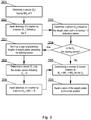
- Fig. 3 presents a diagram of the method according to the present invention.
- the described process uses the following variables that are set up prior to invoking the procedure:
- the method shown in Fig. 3 starts at step (301) from determining a sensor (S T ) having MN A of 0. Therefore S T is the first sensor positioned above the weight stack. Based on this, and the knowledge if a sequence of sensors(142 - 146), there may be determined a sensor S T-1 following the S T sensor in the direction of the engaging movement (160).
- the process awaits detection of a marker by the sensor S T-1 following the S T .
- the distance between S T and S T-1 is considered a minimum travel distance required to count an exercise repetition.
- the S T-1 sensor has detected a marker it means that it may be determined how many weight plates (110 - 117) have been moved in order to later count total weight.
- the method determines a sensor (142 - 146) closest to the weight stack start (closest to the bottom in case of a vertical system or in other words closest to the starting sensor (146)) and at the same time having more than 0 detected markers.
- a sensor may be marked as S B referring to a bottom sensor.
- step (304) the process verifies whether the S B sensor is the starting sensor e.g. (146) taking into account said direction of an engaging movement (160) as shown in Fig. 1B .
- the method determines (305) a number of moved markers (120 - 127) as: M C + MN A + MN O for the S B .
- step (305) the process proceeds to awaiting (306) a return of the weight plates (110 - 117) to the initial position.
- a travel distance required to detect weight may be reduced to the distance D when the first marker (taking the direction of engaging movement into account; i.e. sensor (143) in Fig. 1B ) is positioned such that it faces a sensor.
- the present method sets (307) a variable H as a sum of predefined heights of weight plates (see for example configuration shown in Fig. 5 ) preceding the starting sensor (146 in Figs. 1A-B ), which may be determined based on the number of markers (110 - 117) preceding the starting sensor (146 in Figs. 1A-B ) as well as the number of markers counted by the starting sensor.
- the method proceeds to awaiting (306) a return of the weight plates (110 - 117) to the initial position.
- a repetition may also be counted when the system switches from an engaging movement to a returning movement.
- Each repetition may be timed and time, repetitions count, travel distance and total weight may be calculated (based on system configuration) and stored in the controller (205) as well as reported to a user's device via said communication module (207).
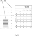
- Figs. 4A-C present system status during an example of weight stack movement.
- this example there are 11 weight plates and 9 sensors.
- Fig. 4A depicts an initial state wherein the start of the weight stack is just above sensor S 8 .
- the MN A , MN U and MN O are defined accordingly.
- MN O is set to 1 only in case of S 7 while in case of all other sensors it is set to 0. This is typically a manual labor required as a system setup in its initial position at which the system is configured.
- the S T sensor is sensor S 4 while the S T-1 sensor is S3.
- Fig. 4B depicts beginning of an engaging movement upwards of the top 6 weight plates.
- the S T has counted 1 marker while the S 5 has counted 2 markers.
- Fig. 4C depicts that the movement is continued.
- the S T-1 has counted 1 marker.
- weight may be counted (as a simple sum) based on a predefined configuration of weight plates in which each weight plate is assigned a weight that may differ between the weight plates (110 - 119).
- travel distance of said 6 weight plates may be measured as predefined measures of the respective 6 weight plates in the direction if the engaging movement (e.g. a sum of all heights of the 6 weight plates).
- Fig. 5 shows an initial system configuration stored in memory.
- the configuration (500) comprises (A) information (501) on a number of markers (120 - 127); (B) information (502) on a sequence of said sensors (142 - 146); (C) information (503) on an initial setup of the system by specifying how many markers (120 - 127) are positioned prior to and after each sensor (142 - 146) taking into account the axis of movement (100).
- the configuration provides information for each sensor (142 - 146) whether it is facing a marker (120 - 127).
- a detection of whether a sensor is considered as facing a marker is implementation dependent in a sense that the facing condition may be defined within a given threshold or range, for example a marker fully within a coverage area of a sensor or a marker 95% within a coverage area of a sensor or a marker 90% within a coverage area of a sensor depending on configuration of the system.
- Other thresholds or ranges are also withing the scope of the present invention.
- a first rail (150) reports sensors S1_1 to S1_5 (142 - 146) in the order given while the second rail (150A) reports sensors S2_1 to S2_5 (142A -146A) in the order given.
- first rail (150) follows the second rail (150A) in the direction of the engaging movement (160).
- a distance between consecutive sensors may be given, in this case 10 cm.
- a distance between consecutive markers may be given, in this case 5 cm (e.g. the corresponding weight plates may have the same height but different weights as specified in the configuration (504).
- weight plates (110 - 117) on which the markers (120 - 127) are positioned have different heights, such heights may be explicitly given as an ordered sequence of values.
- a weight plate common weight may be given e.g. 10000g or an ordered list of weights per the associated weight plates may be given.
- the present invention may take the form of an entirely hardware embodiment, an entirely software embodiment (including firmware, resident software, micro-code, etc.) or an embodiment combining software and hardware aspects that may all generally be referred to herein as a "circuit", "module” or "system”.
- the present invention may take the form of a computer program product embodied in any tangible medium of expression having computer usable program code embodied in the medium.
- the aforementioned method for counting spatially arranged, moving markers may be performed and/or controlled by one or more computer programs.
- Such computer programs are typically executed by utilizing the computing resources in a computing device.
- Applications are stored on a non-transitory medium.
- An example of a non-transitory medium is a non-volatile memory, for example a flash memory while an example of a volatile memory is RAM.
- the computer instructions are executed by a processor.
- These memories are exemplary recording media for storing computer programs comprising computer-executable instructions performing all the steps of the computer-implemented method according the technical concept presented herein.
Landscapes
- Engineering & Computer Science (AREA)
- Physics & Mathematics (AREA)
- Health & Medical Sciences (AREA)
- Theoretical Computer Science (AREA)
- Mathematical Physics (AREA)
- General Physics & Mathematics (AREA)
- Computer Hardware Design (AREA)
- Computing Systems (AREA)
- Life Sciences & Earth Sciences (AREA)
- Biophysics (AREA)
- Orthopedic Medicine & Surgery (AREA)
- General Health & Medical Sciences (AREA)
- Physical Education & Sports Medicine (AREA)
- Measurement Of The Respiration, Hearing Ability, Form, And Blood Characteristics Of Living Organisms (AREA)
- Length Measuring Devices With Unspecified Measuring Means (AREA)
Abstract
Description
- The present invention relates to a system and method for counting spatially arranged, moving markers positioned on corresponding objects. In particular, the present invention relates to a system for counting markers, present in a moving group, by sensors for detecting weight of at least one weight stack plate moved in a given weightlifting machine.
- Prior art of "Sensor arrays for exercise equipment and methods to operate the same"
US 20070213183 A1 , discloses a linear array of sensors. The array of sensors includes a plurality of sensors positioned adjacent and opposite the resting position of each weight plate, and at equally spaced locations above the example stack of weights up to the highest travel position attainable by the top weight plate of the example stack of weights. The example sensor array is enclosed in, covered and/or attached to any variety of housing and/or mounting bracket. - A drawback of this solution is that there must be present a lot of sensors wherein the number of sensors greatly exceeds the number of weight plates because the sensors must extend up to the highest travel position attainable by the top weight plate.
- Therefore, due to the number of required sensors this solution is also ineffective with relation to cost.
- There have been attempts to mitigate this problem so that the number of sensors is lower than the number of weight plates in order to decrease the cost of the sensors system.
- Further, the lower the number of required sensors the lower power consumption of the entire system, which is often battery powered.
- Such solution is present in
EP3542874 entitled "System and method for assisting a weightlifting workout" describes a system where distances between the sensors are set during mounting and setup and are fixed for a given weight stack device. Nevertheless, these distances are a multiplication of a height of a single weight plate, for example four weight plates distance equals 10 cm for a weight plate having 2,5 cm height. - A disadvantage of this solution is that it cannot immediately detect a moved weight because a weight stack must be moved (typically lifted) by a distance (typically height) equal to a spread of sensors so that one may determine how many markers (weight plates) have been moved.
- There is also a problem arising from the fact that different weight stacks having different weight plate sizes will require different rails of sensors where such sensors have different spacing.
- Such system is also not suitable to support weight stacks having weight plates of different sizes (e.g. weight plates of increasing height).
- It would be advantageous to present a solution where the aforementioned drawbacks would be obviated.
- The aim of the development of the present invention is therefore an improved and cost effective system and method counting spatially arranged, moving markers.
- An object of the present invention is a method for counting spatially arranged, moving markers wherein said markers are arranged to move along a movement axis being parallel to a sensors axis of sensors configured to detect said markers during movement, whereas there are fewer sensors than markers, the method being characterized in that it comprises the steps of: providing information on a number of markers; providing information on a sequence of said sensors; providing information on an initial setup of the system by specifying how many markers are preceding and following each sensor taking into account the axis of movement and a direction of an engaging movement; arranging said sensors, in said initial setup, such that at least two of the sensors are arranged such that all the markers precede them taking into account the axis of movement and said direction of the engaging movement; determining a sensor ST having 0 following markers and a sensor ST-1 following the ST sensor in the direction of the engaging movement; awaiting detection of a marker by the sensor ST-1; determining a sensor SB closest to the starting sensor taking into account said direction of an engaging movement and at the same time having more than 0 detected markers; verifying whether the SB sensor is the starting sensor and in case it is not, determining a number of moved markers as a sum of detected markers and following markers for the SB.
- Preferably, the method further comprises the steps of: in the case the verifying step is positive, setting a variable H as a sum of predefined heights of objects associated with said markers preceding the starting sensor based on the number of markers preceding the starting sensor as well as the number of markers counted by the starting sensor; determining a sensor STT as the closest sensor following ST - H; and awaiting detection of a marker by the sensor STT.
- Preferably, said number of moved markers is increased by 1 when the SB is facing a marker.
- Preferably, said information on an initial setup of the system comprises a list defining heights of all objects associated with said markers.
- Preferably, said information on an initial setup of the system comprises a list defining weights of all objects associated with said markers whereas after said verifying step the method is configured to provide a total weight as a sum of weight of all objects associated with said moved markers.
- Preferably, the method further comprises a step of awaiting a return of the weight plates to the initial position and increasing a counter of repetitions.
- Preferably, said information on an initial setup of the system further comprises information on whether each sensor is facing a marker.
- Preferably, said sensors are mounted on at least one rail being configured to be connectable to other such rails in order to form longer rails along said sensors axis.
- Another object of the present invention is a computer program comprising program code means for performing all the steps of the computer-implemented method according to the present invention when said program is run on a computer.
- Another object of the present invention is a computer readable medium storing computer-executable instructions performing all the steps of the computer-implemented method according to the present invention when executed on a computer.
- Another object of the present invention is a system for counting spatially arranged, moving markers wherein said markers are arranged to move along a movement axis being parallel to a sensors axis of sensors configured to detect said markers during movement, whereas there are fewer sensors than markers, the system being characterized in that: a configuration stored in a memory comprises: information on a number of markers; information on a sequence of said sensors; information on an initial setup of the system by specifying how many markers are preceding and following each sensor taking into account the axis of movement and a direction of an engaging movement; at least two of the sensors are arranged in said initial setup, such that all the markers precede them taking into account the axis of movement and the direction of the engaging movement; a controller configured to execute the steps of: determining a sensor ST having 0 following markers and a sensor ST-1 following the ST sensor in the direction of the engaging movement; awaiting detection of a marker by the sensor ST-1; determining a sensor SB closest to the starting sensor taking into account said direction of an engaging movement and at the same time having more than 0 detected markers; verifying whether the SB sensor is the starting sensor and in case it is not, determining a number of moved markers as a sum of detected markers and following markers for the SB.
- Preferably, one of said sensors is arranged facing or preceding a first marker being the starting marker in said spatially arranged group of markers taking into account a direction of an engaging movement.
- Preferably, said sensors are arranged on at least two connected rails arranged along the sensors axis wherein each rail is configured to provide a report to the controller wherein such report comprises sensors identifiers and sensors sequence.
- Preferably, said controller is physically separated from said rails.
- Preferably, said controller is further configured to execute the steps of: in the case the verifying step is positive, setting a variable H as a sum of predefined heights of objects associated with said markers preceding the starting sensor based on the number of markers preceding the starting sensor as well as the number of markers counted by the starting sensor; determining a sensor STT as the closest sensor following position ST - H; and awaiting detection of a marker by the sensor STT.
- These and other objects of the invention presented herein, are accomplished by providing a counting spatially arranged, moving markers. Further details and features of the present invention, its nature and various advantages will become more apparent from the following detailed description of the preferred embodiments shown in a drawing, in which:
-
Fig. 1A presents a basic configuration of the present system; -
Fig. 1B presents another configuration of the present system; -
Fig. 2 presents a diagram of the system according to the present invention; -
Fig. 3 presents a diagram of the method according to the present invention; -
Figs. 4A-C present system status during an example of weight stack movement; and -
Fig. 5 shows example of an initial system configuration stored in memory. - Some portions of the detailed description which follows are presented in terms of data processing procedures, steps or other symbolic representations of operations on data bits that can be performed on computer memory. Therefore, a computer executes such logical steps thus requiring physical manipulations of physical quantities.
- Usually these quantities take the form of electrical or magnetic signals capable of being stored, transferred, combined, compared, and otherwise manipulated in a computer system. For reasons of common usage, these signals are referred to as bits, packets, messages, values, elements, symbols, characters, terms, numbers, or the like.
- Additionally, all of these and similar terms are to be associated with the appropriate physical quantities and are merely convenient labels applied to these quantities. Terms such as "processing" or "creating" or "transferring" or "executing" or "determining" or "detecting" or "obtaining" or "selecting" or "calculating" or "generating" or the like, refer to the action and processes of a computer system that manipulates and transforms data represented as physical (electronic) quantities within the computer's registers and memories into other data similarly represented as physical quantities within the memories or registers or other such information storage.
- A computer-readable (storage) medium, such as referred to herein, typically may be non-transitory and/or comprise a non-transitory device. In this context, a non-transitory storage medium may include a device that may be tangible, meaning that the device has a concrete physical form, although the device may change its physical state. Thus, for example, non-transitory refers to a device remaining tangible despite a change in state.
- As utilized herein, the term "example" means serving as a non-limiting example, instance, or illustration. As utilized herein, the terms "for example" and "e.g." introduce a list of one or more non-limiting examples, instances, or illustrations.
- The system and method according to the present invention take into account that a sequence of sensors is known wherein the system comprises at least two sensors arranged along an axis parallel to an axis of movement of corresponding markers positioned on weight plates (or objects in general).
-
Fig 1A presents a basic configuration of the present system wherein there is an axis of movement (100) positioned vertically, along which weight plates (110 - 117) are configured to be moved. This mechanical arrangement is not shown but is evident to a person skilled in the art of weightlifting machines. Upon exertion of a force the weight plates are configured to be moved along the movement axis (in an engaging direction) and return back typically due to gravity forces (in a returning direction being opposite to the engaging direction). - Each weight plate (110 - 117) has a corresponding marker (120 - 127) configured to be detected by a suitable sensor (142 - 146) when such marker passes a detection area covered by such sensor. The number of weight plates (110 - 117) is known and is a parameter of the system provided by means of defining a sequence of sensors (142 - 146). Typically, the markers (120 - 127) are facing the corresponding sensors (142 - 146).
- The sensors (142 - 146) are positioned along an axis parallel (150) to the axis of movement (100). For the ease of mounting, the sensors (142 - 146) may be positioned on a suitable rail (141), which might house typical components such as power lines, data lines, a controller chip etc, which are typical modules allowing such sensors (142 - 146) to operate.
- The rail (141) may be made of a relatively rigid material such as hard plastic in order to protect the sensors (142 - 146) and components mounted therein.
- The rail (141) may also function as an element maintaining a fixed positioning of the sensors (142 - 146), which is beneficial for a purpose of mounting the sensors (142 - 146) on a target weight stack device.
- Such rails (141) may be manufactured in one size (e.g. 100cm) or in several basic sizes (e.g. 25cm, 50cm and 100cm) and optionally comprise a connector (at one or both of its ends) so that the rails (141) may be connected an operate as a single system.
- In case of connectable rails (141), each rail (141) may comprise its own controller in order to form a system as shown in
Fig. 2 or the controller may be separated and configured to control a plurality of such rails (141). Connected rails (141) may also have a common power source. - To this end, each rail (141) is aware of its sensors (142 - 146) and may provide a report to a controller wherein such report comprises sensors identifiers, sensors sequence and preferably a length of the rail (141). Based on this, a controller may correctly identify sensors (142 - 146) from different rails (141) and act in view of system configuration as explained above.
- The sequence of sensors (142 - 146) is known (in this case 5) and the distance D between consecutive sensors is also known. The distance D need not be a multiple of a height of each weight plate (110 - 117) and thus allows having weight plates (110 - 117) of different heights on the same weight stack.
- The system assumes a known configuration of said system at rest (i.e. an initial position of the markers (120 - 127) with respect to the sensors (142 - 146)). In particular, it is known how many markers (120 - 127) are positioned prior to (preceding markers) and after (following markers) each sensor taking into account the axis of movement (100) and the direction of the engaging movement (160). In other words, the present system does not need to be aware of exact positions of respective markers (weight plates).
- Usually the markers (120 - 127) move in a subgroup as not all weight plates (110 - 117) are typically lifted. Nevertheless, in rare cases all markers (120 - 127) will move.
- In another embodiment of the present invention, the distance D between consecutive sensors may differ, but it must be known to the system in relation to all consecutive sensor pairs.
- In yet another example, there is not present the requirement for it to be known a'priori how many markers (110 - 117) are positioned prior to and after each sensor taking into account the axis of movement (100). In such a case there must be known a distance M between markers (e.g. between centre points of such markers). This is useful because based on these distances (i.e. distances between consecutive sensors, distances between consecutive markers, marker size) the system may determine how many markers (120 - 127) are positioned prior to and after each sensor taking into account the axis of movement (100) and the direction of the engaging movement (160).
- Nevertheless, this embodiment is less preferred than the first embodiment defining (as a configuration, example of which is shown in
Fig. 5 ) exactly how many markers (120 -127) are positioned prior to (preceding markers) and after (following markers) each sensor taking into account the axis of movement (100). - In a preferred embodiment, the markers (120 - 127) are positioned between the starting sensor ((146) as shown in
Fig. 1A ) and an ending sensor (142) taking into account a direction of an engaging movement (160). Further, the preferred embodiment has two ending sensors (142, 143), taking into account said direction of an engaging movement (160), following the weight stack at rest i.e. all weight plates (110 - 117) with markers (120 - 127). - In an alternative embodiment, the markers (120 - 129) may be positioned also below (preceding) the starting sensor (146) taking into account said direction of an engaging movement (160) as shown in
Fig. 1B . In such case the method according to the present invention must be modified as shown inFig. 3 (steps (307 - 309) and take into account that a weight stack must be moved by a distance greater than a distance D between the sensors. - Correspondingly, a starting marker (127 in
Fig. 1A and 129 inFig. 1B ) is considered being the last marker in a spatially arranged group of markers (120 - 127, 120 - 129) taking into account a direction of an engaging movement (160). - As an example, in case of a vertical weight stack having an engaging motion of markers directed upwards, the starting sensor is the one positioned lowest (146) while the starting marker is the last marker (127 in
Fig. 1A ) i.e. a weight stack starting marker. In case of left of right oriented direction of the engaging motion, these naming definitions have to be modified accordingly. - The present solution eliminates a need of adjusting the sensors (142 - 146) setup (typically on the rail (141) to the sizes of the weight plates (110 - 117) as well as allows use of the system on weight stack machines using different weight plates (110 - 117) of differing weights and/or heights.
- Said adjusting process is meant as eliminating a need of physical adjusting because there is still present a configuration in the applicable parameters stored in memory of the system.
- Another advantage of the present system is that the mounting of the system on a weight stack machine need not be very precise as in case of prior art systems. This is a result of a focus of the present solution on relative positioning between the sensors (142 - 146) and the markers (120 - 129) and not on their absolute positioning.
- As will be described later, the present method minimizes a travel distance required in order to detect a number of lifted weight plates (110 - 117) comprising said markers (120 - 127).
-
Fig. 1B shows another setup of the present system, in which the number of weight plates has been increased (110 - 119) while keeping the same rail (141) and the number of sensors (142 - 146). -
Fig. 2 presents a diagram of the system according to the present invention. The system is a typically mounted within said rail (141). - The system may be realized using dedicated components or custom made FPGA or ASIC circuits. The system comprises a data bus (201) communicatively coupled to a memory (204). Additionally, other components of the system are communicatively coupled to the system bus (201) so that they may be managed by a controller (205).
- The memory (204) may store computer program or programs executed by the controller (205) in order to execute steps of the method according to the present invention. It may also store any configuration parameters as explained above and further with reference to
Fig. 5 . - The sensors (206) may be powered from a battery of from the mains via a power supply (203). The controller (205) will usually be configured to provide data, via a communication module (207), to an external device such as a smartphone, which may also be used to setup and control the system.
- Optionally, the system may comprise a proximity module (202) such as an RFID (or Bluetooth LE) sensor, that may be used in order to identify particular users operating the system. Such user may be identified using a smartphone comprising an RFID functionality or a suitable workout garment, such as a glove, comprising an RFID functionality configured to identify a particular user. Based on such identification a connection may be set up with an application executed on such user's device e.g. smartphone, tablet etc.
- As already explained, the system may optionally comprise connected rails (141) arrangement that form the sensors module (206) in case two or more rails (141) of sensors (142 - 146) are connected.
-
Fig. 3 presents a diagram of the method according to the present invention. The described process uses the following variables that are set up prior to invoking the procedure: - MNA - initial number of markers after a given sensor taking the direction of movement into account;
- MNU - initial number of markers preceding a given sensor taking the direction of movement into account;
- MNO - initial presence of a marker in front of a given sensor (0 or 1 / true or false); (this parameter is optional since a system may be configured such that none of the markers are facing any sensor, however having this parameter gives more precision and flexibility);
- MC - number of markers counted by a given sensor, initially 0 for all sensors;
- The method shown in
Fig. 3 starts at step (301) from determining a sensor (ST) having MNA of 0. Therefore ST is the first sensor positioned above the weight stack. Based on this, and the knowledge if a sequence of sensors(142 - 146), there may be determined a sensor ST-1 following the ST sensor in the direction of the engaging movement (160). - Next, at step (302), the process awaits detection of a marker by the sensor ST-1 following the ST. The distance between ST and ST-1 is considered a minimum travel distance required to count an exercise repetition. When the ST-1 sensor has detected a marker it means that it may be determined how many weight plates (110 - 117) have been moved in order to later count total weight.
- Subsequently, at step (303), the method determines a sensor (142 - 146) closest to the weight stack start (closest to the bottom in case of a vertical system or in other words closest to the starting sensor (146)) and at the same time having more than 0 detected markers. Such sensor may be marked as SB referring to a bottom sensor.
- Further, at step (304), the process verifies whether the SB sensor is the starting sensor e.g. (146) taking into account said direction of an engaging movement (160) as shown in
Fig. 1B . - In case it is not, the method determines (305) a number of moved markers (120 - 127) as:
MC + MNA + MNO for the SB. - After step (305) the process proceeds to awaiting (306) a return of the weight plates (110 - 117) to the initial position.
- From the equation above it stems that a travel distance required to detect weight may be reduced to the distance D when the first marker (taking the direction of engaging movement into account; i.e. sensor (143) in
Fig. 1B ) is positioned such that it faces a sensor. - In the case the check of step (304) is positive, the present method sets (307) a variable H as a sum of predefined heights of weight plates (see for example configuration shown in
Fig. 5 ) preceding the starting sensor (146 inFigs. 1A-B ), which may be determined based on the number of markers (110 - 117) preceding the starting sensor (146 inFigs. 1A-B ) as well as the number of markers counted by the starting sensor. - Next, at step (308) the present process determines a sensor (STT) as the closest sensor following position ST - H and awaits (309) detection of a marker by the sensor (STT) (MC = 1).
- Subsequently, the method proceeds to awaiting (306) a return of the weight plates (110 - 117) to the initial position.
- A repetition may also be counted when the system switches from an engaging movement to a returning movement. Each repetition may be timed and time, repetitions count, travel distance and total weight may be calculated (based on system configuration) and stored in the controller (205) as well as reported to a user's device via said communication module (207).
- It is clear to one skilled in the art that in order to correctly update the variables MC, MNA and MNo the system must be able to detect a direction of movement (engaging or returning) of the weight plates. This may be effected by known methods, one of which is presented in the Applicant's co-pending European Patent Applications
EP18461537.5 EP19461616.5 -
Figs. 4A-C present system status during an example of weight stack movement. In this example there are 11 weight plates and 9 sensors. -
Fig. 4A depicts an initial state wherein the start of the weight stack is just above sensor S8. The MNA, MNU and MNO are defined accordingly. For example, MNO is set to 1 only in case of S7 while in case of all other sensors it is set to 0. This is typically a manual labor required as a system setup in its initial position at which the system is configured. - At this stage it is determined that the ST sensor is sensor S4 while the ST-1 sensor is S3.
-
Fig. 4B depicts beginning of an engaging movement upwards of the top 6 weight plates. In this state, the ST has counted 1 marker while the S5 has counted 2 markers. -
Fig. 4C depicts that the movement is continued. The ST-1 has counted 1 marker. At this stage it is determined that the SB sensor is sensor S5. Therefore, the number of moved markers may be calculated as 4 (markers counted by the SB) + 2 (markers above the SB in the initial state) + 0 (markers on (in front of / facing) the SB in the initial state) = 6. - Having the number of top 6 weight plates moved, weight may be counted (as a simple sum) based on a predefined configuration of weight plates in which each weight plate is assigned a weight that may differ between the weight plates (110 - 119).
- Similarly, travel distance of said 6 weight plates may be measured as predefined measures of the respective 6 weight plates in the direction if the engaging movement (e.g. a sum of all heights of the 6 weight plates).
-
Fig. 5 shows an initial system configuration stored in memory. The configuration (500) comprises (A) information (501) on a number of markers (120 - 127); (B) information (502) on a sequence of said sensors (142 - 146); (C) information (503) on an initial setup of the system by specifying how many markers (120 - 127) are positioned prior to and after each sensor (142 - 146) taking into account the axis of movement (100). - Optionally, the configuration provides information for each sensor (142 - 146) whether it is facing a marker (120 - 127).
- A detection of whether a sensor is considered as facing a marker (120 - 127) is implementation dependent in a sense that the facing condition may be defined within a given threshold or range, for example a marker fully within a coverage area of a sensor or a marker 95% within a coverage area of a sensor or a marker 90% within a coverage area of a sensor depending on configuration of the system. Other thresholds or ranges are also withing the scope of the present invention.
- In this example a first rail (150) reports sensors S1_1 to S1_5 (142 - 146) in the order given while the second rail (150A) reports sensors S2_1 to S2_5 (142A -146A) in the order given.
- It is also known that the first rail (150) follows the second rail (150A) in the direction of the engaging movement (160).
- A distance between consecutive sensors may be given, in this
case 10 cm. Correspondingly, a distance between consecutive markers may be given, in thiscase 5 cm (e.g. the corresponding weight plates may have the same height but different weights as specified in the configuration (504). - In case the weight plates (110 - 117) on which the markers (120 - 127) are positioned have different heights, such heights may be explicitly given as an ordered sequence of values.
- In a similar manner a weight plate common weight may be given e.g. 10000g or an ordered list of weights per the associated weight plates may be given.
- At least parts of the methods according to the invention may be computer implemented. Accordingly, the present invention may take the form of an entirely hardware embodiment, an entirely software embodiment (including firmware, resident software, micro-code, etc.) or an embodiment combining software and hardware aspects that may all generally be referred to herein as a "circuit", "module" or "system".
- Furthermore, the present invention may take the form of a computer program product embodied in any tangible medium of expression having computer usable program code embodied in the medium.
- It can be easily recognized, by one skilled in the art, that the aforementioned method for counting spatially arranged, moving markers may be performed and/or controlled by one or more computer programs. Such computer programs are typically executed by utilizing the computing resources in a computing device. Applications are stored on a non-transitory medium. An example of a non-transitory medium is a non-volatile memory, for example a flash memory while an example of a volatile memory is RAM. The computer instructions are executed by a processor. These memories are exemplary recording media for storing computer programs comprising computer-executable instructions performing all the steps of the computer-implemented method according the technical concept presented herein.
- While the invention presented herein has been depicted, described, and has been defined with reference to particular preferred embodiments, such references and examples of implementation in the foregoing specification do not imply any limitation on the invention. It will, however, be evident that various modifications and changes may be made thereto without departing from the broader scope of the technical concept. The presented preferred embodiments are exemplary only, and are not exhaustive of the scope of the technical concept presented herein.
- Accordingly, the scope of protection is not limited to the preferred embodiments described in the specification, but is only limited by the claims that follow.
Claims (15)
- A method for counting spatially arranged, moving markers (120 - 127)• wherein said markers (120 - 127) are arranged to move along a movement axis (100) being parallel to a sensors axis (150) of sensors (142 - 146) configured to detect said markers (120 - 127) during movement, whereas there are fewer sensors (142 - 146) than markers (120 - 127),the method being characterized in that it comprises the steps of:• providing information on a number of markers (120 - 127);• providing information on a sequence of said sensors (142 - 146);• providing information on an initial setup of the system by specifying how many markers (120 - 127) are preceding and following each sensor (142 - 146) taking into account the axis of movement (100) and a direction of an engaging movement (160);• arranging said sensors, in said initial setup, such that at least two of the sensors (142 - 146) are arranged such that all the markers (120 - 127) precede them taking into account the axis of movement (100) and said direction of the engaging movement (160);• determining (301) a sensor ST having 0 following markers and a sensor ST-1 following the ST sensor in the direction of the engaging movement (160);• awaiting (302) detection of a marker by the sensor ST-1;• determining (303) a sensor SB closest to the starting sensor (146) taking into account said direction of an engaging movement (160) and at the same time having more than 0 detected markers;• verifying (304) whether the SB sensor is the starting sensor (146) and in case it is not, determining (305) a number of moved markers (120 - 127) as a sum of detected markers and following markers for the SB.
- The method according to claim 1 wherein the method further comprises the steps of:• in the case the verifying step (304) is positive, setting (307) a variable H as a sum of predefined heights of objects associated with said markers (120 - 127) preceding the starting sensor (146) based on the number of markers (110 - 117) preceding the starting sensor (146) as well as the number of markers counted by the starting sensor;• determining (308) a sensor STT as the closest sensor following ST - H; and• awaiting (309) detection of a marker by the sensor STT.
- The method according to claim 1 wherein said number of moved markers is increased by 1 when the SB is facing a marker.
- The method according to claim 1 wherein said information on an initial setup of the system comprises a list defining heights of all objects associated with said markers (110 - 117).
- The method according to claim 1 wherein said information on an initial setup of the system comprises a list defining weights of all objects associated with said markers (110 - 117) whereas after said verifying step (304) the method is configured to provide a total weight as a sum of weight of all objects (110 - 117) associated with said moved markers (120 - 127).
- The method according to claim 1 wherein the method further comprises a step of awaiting (306) a return of the weight plates (110 - 117) to the initial position and increasing a counter of repetitions.
- The method according to claim 1 wherein said information on an initial setup of the system further comprises information on whether each sensor is facing a marker.
- The method according to claim 1 wherein said sensors (142 - 146) are mounted on at least one rail (141) being configured to be connectable to other such rails (141) in order to form longer rails (141) along said sensors axis (150).
- A computer program comprising program code means for performing all the steps of the computer-implemented method according to claim 1 when said program is run on a computer.
- A computer readable medium storing computer-executable instructions performing all the steps of the computer-implemented method according to claim 1 when executed on a computer.
- A system for counting spatially arranged, moving markers (120 - 127)• wherein said markers (120 - 127) are arranged to move along a movement axis (100) being parallel to a sensors axis (150) of sensors (142 - 146) configured to detect said markers (120 - 127) during movement, whereas there are fewer sensors (142 - 146) than markers (120 - 127),the system being characterized in that:• a configuration stored in a memory (204) comprises:∘ information on a number of markers (120 - 127);∘ information on a sequence of said sensors (142 - 146);∘ information on an initial setup of the system by specifying how many markers (120 - 127) are preceding and following each sensor (142 - 146) taking into account the axis of movement (100) and a direction of an engaging movement (160);• at least two of the sensors (142 - 146) are arranged in said initial setup, such that all the markers (120 - 127) precede them taking into account the axis of movement (100) and the direction of the engaging movement (160);• a controller (205) configured to execute the steps of:∘ determining (301) a sensor ST having 0 following markers and a sensor ST-1 following the ST sensor in the direction of the engaging movement (160);∘ awaiting (302) detection of a marker by the sensor ST-1;∘ determining (303) a sensor SB closest to the starting sensor (146) taking into account said direction of an engaging movement (160) and at the same time having more than 0 detected markers;∘ verifying (304) whether the SB sensor is the starting sensor (146) and in case it is not, determining (305) a number of moved markers (120 - 127) as a sum of detected markers and following markers for the SB.
- The system according to claim 11 wherein one of said sensors (142 - 146) is arranged facing or preceding a first marker (127) being the starting marker in said spatially arranged group of markers (120 - 127) taking into account a direction of an engaging movement (160).
- The system according to claim 11 wherein said sensors (142 - 146) are arranged on at least two connected rails (141) arranged along the sensors axis (150) wherein each rail (141) is configured to provide a report to the controller (205) wherein such report comprises sensors identifiers and sensors sequence.
- The system according to claim 13 wherein said controller (205) is physically separated from said rails (141).
- The system according to claim 11 wherein said controller is further configured to execute the steps of:• in the case the verifying step (304) is positive, setting (307) a variable H as a sum of predefined heights of objects associated with said markers (120 - 127) preceding the starting sensor (146) based on the number of markers (110 - 117) preceding the starting sensor (146) as well as the number of markers counted by the starting sensor;• determining (308) a sensor STT as the closest sensor following position ST - H; and• awaiting (309) detection of a marker by the sensor STT.
Priority Applications (8)
| Application Number | Priority Date | Filing Date | Title |
|---|---|---|---|
| EP20461509.0A EP3862056B1 (en) | 2020-02-04 | 2020-02-04 | System and method for counting spatially arranged, moving markers |
| ES20461509T ES2907973T3 (en) | 2020-02-04 | 2020-02-04 | System and method for counting spatially arranged mobile markers |
| PL20461509T PL3862056T3 (en) | 2020-02-04 | 2020-02-04 | System and method for counting spatially arranged, moving markers |
| AU2020427245A AU2020427245A1 (en) | 2020-02-04 | 2020-12-09 | System and method for counting spatially arranged, moving markers |
| PCT/EP2020/085383 WO2021155979A1 (en) | 2020-02-04 | 2020-12-09 | System and method for counting spatially arranged, moving markers |
| CN202080095659.3A CN115066279B (en) | 2020-02-04 | 2020-12-09 | System and method for counting spatially arranged movement marks |
| US17/797,444 US12346146B2 (en) | 2020-02-04 | 2020-12-09 | System and method for counting spatially arranged, moving markers |
| US19/231,513 US20250295955A1 (en) | 2020-02-04 | 2025-06-08 | System and method for counting spatially arranged, moving markers |
Applications Claiming Priority (1)
| Application Number | Priority Date | Filing Date | Title |
|---|---|---|---|
| EP20461509.0A EP3862056B1 (en) | 2020-02-04 | 2020-02-04 | System and method for counting spatially arranged, moving markers |
Publications (2)
| Publication Number | Publication Date |
|---|---|
| EP3862056A1 true EP3862056A1 (en) | 2021-08-11 |
| EP3862056B1 EP3862056B1 (en) | 2021-12-29 |
Family
ID=69500696
Family Applications (1)
| Application Number | Title | Priority Date | Filing Date |
|---|---|---|---|
| EP20461509.0A Active EP3862056B1 (en) | 2020-02-04 | 2020-02-04 | System and method for counting spatially arranged, moving markers |
Country Status (7)
| Country | Link |
|---|---|
| US (1) | US12346146B2 (en) |
| EP (1) | EP3862056B1 (en) |
| CN (1) | CN115066279B (en) |
| AU (1) | AU2020427245A1 (en) |
| ES (1) | ES2907973T3 (en) |
| PL (1) | PL3862056T3 (en) |
| WO (1) | WO2021155979A1 (en) |
Citations (4)
| Publication number | Priority date | Publication date | Assignee | Title |
|---|---|---|---|---|
| US20070213183A1 (en) | 2006-03-08 | 2007-09-13 | Menektchiev Alexandre K | Sensor arrays for exercise equipment and methods to operate the same |
| US20120220429A1 (en) * | 2011-02-24 | 2012-08-30 | Casio Information Systems Co., Ltd. | Training management device, training device and storage medium |
| CN106267732B (en) * | 2016-08-23 | 2019-06-07 | 爱跑步(深圳)运动器材有限公司 | The monitoring system and its monitoring method of strength instrument service condition |
| EP3542874A1 (en) | 2018-03-18 | 2019-09-25 | Heavy Kinematic Machines Sp. z o. o. | System and method for assisting a weightlifting workout |
Family Cites Families (9)
| Publication number | Priority date | Publication date | Assignee | Title |
|---|---|---|---|---|
| US6793607B2 (en) * | 2002-01-22 | 2004-09-21 | Kinetic Sports Interactive | Workout assistant |
| US20180008865A9 (en) * | 2004-05-10 | 2018-01-11 | Koko Fitness, Inc. | Exercising apparatus |
| US20080242509A1 (en) * | 2007-03-30 | 2008-10-02 | Menektchiev Alexandre K | Methods and apparatus to control workouts on strength machines |
| US8062182B2 (en) * | 2009-02-24 | 2011-11-22 | Tuffstuff Fitness Equipment, Inc. | Exercise monitoring system |
| US20120004076A1 (en) * | 2010-06-30 | 2012-01-05 | Fenster Mrako A | Apparatus for Counting Repetitions of an Exercise Device |
| US8109008B1 (en) * | 2010-11-09 | 2012-02-07 | Pelstar, Llc | Digital height rod |
| CN208448518U (en) * | 2017-09-22 | 2019-02-01 | 深圳市云康创新网络科技有限公司 | The sports apparatus of exercise data is shared in capture |
| US11117018B2 (en) * | 2018-09-05 | 2021-09-14 | Vadim MALIS | System for measuring, monitoring and displaying physical parameters of exercises on selectorized fitness machines |
| US11883717B2 (en) * | 2020-01-21 | 2024-01-30 | Claudio Ploumis, Inc. | Weightlifting machine and method of use |
-
2020
- 2020-02-04 EP EP20461509.0A patent/EP3862056B1/en active Active
- 2020-02-04 ES ES20461509T patent/ES2907973T3/en active Active
- 2020-02-04 PL PL20461509T patent/PL3862056T3/en unknown
- 2020-12-09 AU AU2020427245A patent/AU2020427245A1/en active Pending
- 2020-12-09 WO PCT/EP2020/085383 patent/WO2021155979A1/en not_active Ceased
- 2020-12-09 CN CN202080095659.3A patent/CN115066279B/en active Active
- 2020-12-09 US US17/797,444 patent/US12346146B2/en active Active
Patent Citations (4)
| Publication number | Priority date | Publication date | Assignee | Title |
|---|---|---|---|---|
| US20070213183A1 (en) | 2006-03-08 | 2007-09-13 | Menektchiev Alexandre K | Sensor arrays for exercise equipment and methods to operate the same |
| US20120220429A1 (en) * | 2011-02-24 | 2012-08-30 | Casio Information Systems Co., Ltd. | Training management device, training device and storage medium |
| CN106267732B (en) * | 2016-08-23 | 2019-06-07 | 爱跑步(深圳)运动器材有限公司 | The monitoring system and its monitoring method of strength instrument service condition |
| EP3542874A1 (en) | 2018-03-18 | 2019-09-25 | Heavy Kinematic Machines Sp. z o. o. | System and method for assisting a weightlifting workout |
Also Published As
| Publication number | Publication date |
|---|---|
| US12346146B2 (en) | 2025-07-01 |
| EP3862056B1 (en) | 2021-12-29 |
| AU2020427245A2 (en) | 2022-08-25 |
| US20220390978A1 (en) | 2022-12-08 |
| ES2907973T3 (en) | 2022-04-27 |
| CN115066279A (en) | 2022-09-16 |
| WO2021155979A1 (en) | 2021-08-12 |
| PL3862056T3 (en) | 2022-04-19 |
| CN115066279B (en) | 2023-08-08 |
| AU2020427245A1 (en) | 2022-08-18 |
Similar Documents
| Publication | Publication Date | Title |
|---|---|---|
| EP1832317A1 (en) | Sensor arrays for exercise equipment and methods to operate the same | |
| DE102014224544B4 (en) | Electromagnetic type keypad, method for driving and detecting an electromagnetic type keypad and coordinate input device | |
| US9703001B2 (en) | Method for automatic recognition of a mobile magnetic object | |
| JP2017122724A5 (en) | ||
| CN103699916A (en) | Method for judging moving direction of RFID (radio frequency identification) tag and electronic equipment | |
| WO2021014781A1 (en) | Counting method, computer program, and counting system | |
| JPWO2014192216A1 (en) | RFID tag reading apparatus, RFID tag reading program, and RFID tag reading method | |
| US12346146B2 (en) | System and method for counting spatially arranged, moving markers | |
| CN109168327B (en) | Method and apparatus for cross-connection detection and mitigation in wireless power transmission networks | |
| CN105288783B (en) | The method for detecting position and device of syringe pump, syringe pump sliding block | |
| EP2650871A3 (en) | Touch sensing device, touch sensing unit, storage medium and touch sensing method | |
| US20250295955A1 (en) | System and method for counting spatially arranged, moving markers | |
| US20140153623A1 (en) | Device for auto baud rate detection | |
| CN104572329A (en) | Fault determination method and device | |
| GB2581748A (en) | Systems and methods for density-based RFID network configuration | |
| EP3542874B1 (en) | System and method for assisting a weightlifting workout | |
| CN107547028A (en) | A kind of method and device of angle of rotor of motor detection | |
| US20090066484A1 (en) | RF tag R/W (reader/writer) control method and control apparatus | |
| US10395075B2 (en) | RFID apparatus and method for communicating with at least one RFID transponder | |
| CN105282647B (en) | MPP sound box control method and access controller | |
| AU2020406504B2 (en) | System and method for a quantitative detection of a movement | |
| JP2014235524A5 (en) | ||
| CN104868898B (en) | A kind of electronic equipment and information processing method | |
| US12453894B2 (en) | System and method for monitoring a free weight system | |
| CN108762567B (en) | Position resolution measuring method and device |
Legal Events
| Date | Code | Title | Description |
|---|---|---|---|
| PUAI | Public reference made under article 153(3) epc to a published international application that has entered the european phase |
Free format text: ORIGINAL CODE: 0009012 |
|
| STAA | Information on the status of an ep patent application or granted ep patent |
Free format text: STATUS: REQUEST FOR EXAMINATION WAS MADE |
|
| 17P | Request for examination filed |
Effective date: 20201211 |
|
| AK | Designated contracting states |
Kind code of ref document: A1 Designated state(s): AL AT BE BG CH CY CZ DE DK EE ES FI FR GB GR HR HU IE IS IT LI LT LU LV MC MK MT NL NO PL PT RO RS SE SI SK SM TR |
|
| GRAP | Despatch of communication of intention to grant a patent |
Free format text: ORIGINAL CODE: EPIDOSNIGR1 |
|
| STAA | Information on the status of an ep patent application or granted ep patent |
Free format text: STATUS: GRANT OF PATENT IS INTENDED |
|
| INTG | Intention to grant announced |
Effective date: 20211006 |
|
| GRAS | Grant fee paid |
Free format text: ORIGINAL CODE: EPIDOSNIGR3 |
|
| GRAA | (expected) grant |
Free format text: ORIGINAL CODE: 0009210 |
|
| STAA | Information on the status of an ep patent application or granted ep patent |
Free format text: STATUS: THE PATENT HAS BEEN GRANTED |
|
| AK | Designated contracting states |
Kind code of ref document: B1 Designated state(s): AL AT BE BG CH CY CZ DE DK EE ES FI FR GB GR HR HU IE IS IT LI LT LU LV MC MK MT NL NO PL PT RO RS SE SI SK SM TR |
|
| REG | Reference to a national code |
Ref country code: GB Ref legal event code: FG4D |
|
| REG | Reference to a national code |
Ref country code: CH Ref legal event code: EP |
|
| REG | Reference to a national code |
Ref country code: AT Ref legal event code: REF Ref document number: 1458239 Country of ref document: AT Kind code of ref document: T Effective date: 20220115 |
|
| REG | Reference to a national code |
Ref country code: IE Ref legal event code: FG4D |
|
| REG | Reference to a national code |
Ref country code: DE Ref legal event code: R096 Ref document number: 602020001468 Country of ref document: DE |
|
| REG | Reference to a national code |
Ref country code: NL Ref legal event code: FP |
|
| REG | Reference to a national code |
Ref country code: LT Ref legal event code: MG9D |
|
| REG | Reference to a national code |
Ref country code: ES Ref legal event code: FG2A Ref document number: 2907973 Country of ref document: ES Kind code of ref document: T3 Effective date: 20220427 |
|
| PG25 | Lapsed in a contracting state [announced via postgrant information from national office to epo] |
Ref country code: RS Free format text: LAPSE BECAUSE OF FAILURE TO SUBMIT A TRANSLATION OF THE DESCRIPTION OR TO PAY THE FEE WITHIN THE PRESCRIBED TIME-LIMIT Effective date: 20211229 Ref country code: LT Free format text: LAPSE BECAUSE OF FAILURE TO SUBMIT A TRANSLATION OF THE DESCRIPTION OR TO PAY THE FEE WITHIN THE PRESCRIBED TIME-LIMIT Effective date: 20211229 Ref country code: FI Free format text: LAPSE BECAUSE OF FAILURE TO SUBMIT A TRANSLATION OF THE DESCRIPTION OR TO PAY THE FEE WITHIN THE PRESCRIBED TIME-LIMIT Effective date: 20211229 Ref country code: BG Free format text: LAPSE BECAUSE OF FAILURE TO SUBMIT A TRANSLATION OF THE DESCRIPTION OR TO PAY THE FEE WITHIN THE PRESCRIBED TIME-LIMIT Effective date: 20220329 |
|
| REG | Reference to a national code |
Ref country code: AT Ref legal event code: MK05 Ref document number: 1458239 Country of ref document: AT Kind code of ref document: T Effective date: 20211229 |
|
| PG25 | Lapsed in a contracting state [announced via postgrant information from national office to epo] |
Ref country code: SE Free format text: LAPSE BECAUSE OF FAILURE TO SUBMIT A TRANSLATION OF THE DESCRIPTION OR TO PAY THE FEE WITHIN THE PRESCRIBED TIME-LIMIT Effective date: 20211229 Ref country code: NO Free format text: LAPSE BECAUSE OF FAILURE TO SUBMIT A TRANSLATION OF THE DESCRIPTION OR TO PAY THE FEE WITHIN THE PRESCRIBED TIME-LIMIT Effective date: 20220329 Ref country code: LV Free format text: LAPSE BECAUSE OF FAILURE TO SUBMIT A TRANSLATION OF THE DESCRIPTION OR TO PAY THE FEE WITHIN THE PRESCRIBED TIME-LIMIT Effective date: 20211229 Ref country code: HR Free format text: LAPSE BECAUSE OF FAILURE TO SUBMIT A TRANSLATION OF THE DESCRIPTION OR TO PAY THE FEE WITHIN THE PRESCRIBED TIME-LIMIT Effective date: 20211229 Ref country code: GR Free format text: LAPSE BECAUSE OF FAILURE TO SUBMIT A TRANSLATION OF THE DESCRIPTION OR TO PAY THE FEE WITHIN THE PRESCRIBED TIME-LIMIT Effective date: 20220330 |
|
| PG25 | Lapsed in a contracting state [announced via postgrant information from national office to epo] |
Ref country code: SM Free format text: LAPSE BECAUSE OF FAILURE TO SUBMIT A TRANSLATION OF THE DESCRIPTION OR TO PAY THE FEE WITHIN THE PRESCRIBED TIME-LIMIT Effective date: 20211229 Ref country code: SK Free format text: LAPSE BECAUSE OF FAILURE TO SUBMIT A TRANSLATION OF THE DESCRIPTION OR TO PAY THE FEE WITHIN THE PRESCRIBED TIME-LIMIT Effective date: 20211229 Ref country code: RO Free format text: LAPSE BECAUSE OF FAILURE TO SUBMIT A TRANSLATION OF THE DESCRIPTION OR TO PAY THE FEE WITHIN THE PRESCRIBED TIME-LIMIT Effective date: 20211229 Ref country code: PT Free format text: LAPSE BECAUSE OF FAILURE TO SUBMIT A TRANSLATION OF THE DESCRIPTION OR TO PAY THE FEE WITHIN THE PRESCRIBED TIME-LIMIT Effective date: 20220429 Ref country code: EE Free format text: LAPSE BECAUSE OF FAILURE TO SUBMIT A TRANSLATION OF THE DESCRIPTION OR TO PAY THE FEE WITHIN THE PRESCRIBED TIME-LIMIT Effective date: 20211229 Ref country code: CZ Free format text: LAPSE BECAUSE OF FAILURE TO SUBMIT A TRANSLATION OF THE DESCRIPTION OR TO PAY THE FEE WITHIN THE PRESCRIBED TIME-LIMIT Effective date: 20211229 |
|
| PG25 | Lapsed in a contracting state [announced via postgrant information from national office to epo] |
Ref country code: AT Free format text: LAPSE BECAUSE OF FAILURE TO SUBMIT A TRANSLATION OF THE DESCRIPTION OR TO PAY THE FEE WITHIN THE PRESCRIBED TIME-LIMIT Effective date: 20211229 |
|
| PG25 | Lapsed in a contracting state [announced via postgrant information from national office to epo] |
Ref country code: MC Free format text: LAPSE BECAUSE OF FAILURE TO SUBMIT A TRANSLATION OF THE DESCRIPTION OR TO PAY THE FEE WITHIN THE PRESCRIBED TIME-LIMIT Effective date: 20211229 Ref country code: IS Free format text: LAPSE BECAUSE OF FAILURE TO SUBMIT A TRANSLATION OF THE DESCRIPTION OR TO PAY THE FEE WITHIN THE PRESCRIBED TIME-LIMIT Effective date: 20220429 |
|
| REG | Reference to a national code |
Ref country code: DE Ref legal event code: R097 Ref document number: 602020001468 Country of ref document: DE |
|
| REG | Reference to a national code |
Ref country code: BE Ref legal event code: MM Effective date: 20220228 |
|
| PG25 | Lapsed in a contracting state [announced via postgrant information from national office to epo] |
Ref country code: LU Free format text: LAPSE BECAUSE OF NON-PAYMENT OF DUE FEES Effective date: 20220204 Ref country code: DK Free format text: LAPSE BECAUSE OF FAILURE TO SUBMIT A TRANSLATION OF THE DESCRIPTION OR TO PAY THE FEE WITHIN THE PRESCRIBED TIME-LIMIT Effective date: 20211229 Ref country code: AL Free format text: LAPSE BECAUSE OF FAILURE TO SUBMIT A TRANSLATION OF THE DESCRIPTION OR TO PAY THE FEE WITHIN THE PRESCRIBED TIME-LIMIT Effective date: 20211229 |
|
| PLBE | No opposition filed within time limit |
Free format text: ORIGINAL CODE: 0009261 |
|
| STAA | Information on the status of an ep patent application or granted ep patent |
Free format text: STATUS: NO OPPOSITION FILED WITHIN TIME LIMIT |
|
| 26N | No opposition filed |
Effective date: 20220930 |
|
| PG25 | Lapsed in a contracting state [announced via postgrant information from national office to epo] |
Ref country code: IE Free format text: LAPSE BECAUSE OF NON-PAYMENT OF DUE FEES Effective date: 20220204 |
|
| PG25 | Lapsed in a contracting state [announced via postgrant information from national office to epo] |
Ref country code: BE Free format text: LAPSE BECAUSE OF NON-PAYMENT OF DUE FEES Effective date: 20220228 |
|
| REG | Reference to a national code |
Ref country code: CH Ref legal event code: PL |
|
| PG25 | Lapsed in a contracting state [announced via postgrant information from national office to epo] |
Ref country code: LI Free format text: LAPSE BECAUSE OF NON-PAYMENT OF DUE FEES Effective date: 20230228 Ref country code: CH Free format text: LAPSE BECAUSE OF NON-PAYMENT OF DUE FEES Effective date: 20230228 |
|
| PG25 | Lapsed in a contracting state [announced via postgrant information from national office to epo] |
Ref country code: MK Free format text: LAPSE BECAUSE OF FAILURE TO SUBMIT A TRANSLATION OF THE DESCRIPTION OR TO PAY THE FEE WITHIN THE PRESCRIBED TIME-LIMIT Effective date: 20211229 Ref country code: CY Free format text: LAPSE BECAUSE OF FAILURE TO SUBMIT A TRANSLATION OF THE DESCRIPTION OR TO PAY THE FEE WITHIN THE PRESCRIBED TIME-LIMIT Effective date: 20211229 |
|
| PG25 | Lapsed in a contracting state [announced via postgrant information from national office to epo] |
Ref country code: HU Free format text: LAPSE BECAUSE OF FAILURE TO SUBMIT A TRANSLATION OF THE DESCRIPTION OR TO PAY THE FEE WITHIN THE PRESCRIBED TIME-LIMIT; INVALID AB INITIO Effective date: 20200204 |
|
| PG25 | Lapsed in a contracting state [announced via postgrant information from national office to epo] |
Ref country code: TR Free format text: LAPSE BECAUSE OF FAILURE TO SUBMIT A TRANSLATION OF THE DESCRIPTION OR TO PAY THE FEE WITHIN THE PRESCRIBED TIME-LIMIT Effective date: 20211229 |
|
| PG25 | Lapsed in a contracting state [announced via postgrant information from national office to epo] |
Ref country code: MT Free format text: LAPSE BECAUSE OF FAILURE TO SUBMIT A TRANSLATION OF THE DESCRIPTION OR TO PAY THE FEE WITHIN THE PRESCRIBED TIME-LIMIT Effective date: 20211229 |
|
| PG25 | Lapsed in a contracting state [announced via postgrant information from national office to epo] |
Ref country code: SI Free format text: LAPSE BECAUSE OF FAILURE TO SUBMIT A TRANSLATION OF THE DESCRIPTION OR TO PAY THE FEE WITHIN THE PRESCRIBED TIME-LIMIT Effective date: 20211229 |
|
| PGFP | Annual fee paid to national office [announced via postgrant information from national office to epo] |
Ref country code: NL Payment date: 20260226 Year of fee payment: 7 |
|
| PGFP | Annual fee paid to national office [announced via postgrant information from national office to epo] |
Ref country code: GB Payment date: 20260227 Year of fee payment: 7 |
|
| PGFP | Annual fee paid to national office [announced via postgrant information from national office to epo] |
Ref country code: ES Payment date: 20260302 Year of fee payment: 7 |
|
| PGFP | Annual fee paid to national office [announced via postgrant information from national office to epo] |
Ref country code: DE Payment date: 20260227 Year of fee payment: 7 |
|
| PGFP | Annual fee paid to national office [announced via postgrant information from national office to epo] |
Ref country code: IT Payment date: 20260219 Year of fee payment: 7 |
|
| PGFP | Annual fee paid to national office [announced via postgrant information from national office to epo] |
Ref country code: FR Payment date: 20260225 Year of fee payment: 7 |
|
| PGFP | Annual fee paid to national office [announced via postgrant information from national office to epo] |
Ref country code: PL Payment date: 20260119 Year of fee payment: 7 |