EP3861966A1 - Armprothese - Google Patents
Armprothese Download PDFInfo
- Publication number
- EP3861966A1 EP3861966A1 EP20401036.7A EP20401036A EP3861966A1 EP 3861966 A1 EP3861966 A1 EP 3861966A1 EP 20401036 A EP20401036 A EP 20401036A EP 3861966 A1 EP3861966 A1 EP 3861966A1
- Authority
- EP
- European Patent Office
- Prior art keywords
- shaft
- connector
- adapter
- arm
- prosthesis
- Prior art date
- Legal status (The legal status is an assumption and is not a legal conclusion. Google has not performed a legal analysis and makes no representation as to the accuracy of the status listed.)
- Withdrawn
Links
- 210000002310 elbow joint Anatomy 0.000 claims abstract description 16
- 210000000707 wrist Anatomy 0.000 claims abstract description 14
- 239000004033 plastic Substances 0.000 claims abstract description 10
- 229920003023 plastic Polymers 0.000 claims abstract description 10
- 210000000245 forearm Anatomy 0.000 claims description 11
- 229910001369 Brass Inorganic materials 0.000 claims description 7
- 239000010951 brass Substances 0.000 claims description 7
- 239000004918 carbon fiber reinforced polymer Substances 0.000 claims description 5
- 210000001503 joint Anatomy 0.000 claims description 5
- 238000004519 manufacturing process Methods 0.000 claims description 5
- 238000000034 method Methods 0.000 claims description 5
- 239000011505 plaster Substances 0.000 claims description 5
- 229920001296 polysiloxane Polymers 0.000 claims description 5
- 238000005259 measurement Methods 0.000 claims description 4
- 230000003014 reinforcing effect Effects 0.000 claims description 4
- OSGAYBCDTDRGGQ-UHFFFAOYSA-L calcium sulfate Inorganic materials [Ca+2].[O-]S([O-])(=O)=O OSGAYBCDTDRGGQ-UHFFFAOYSA-L 0.000 claims description 3
- ZOMBKNNSYQHRCA-UHFFFAOYSA-J calcium sulfate hemihydrate Chemical compound O.[Ca+2].[Ca+2].[O-]S([O-])(=O)=O.[O-]S([O-])(=O)=O ZOMBKNNSYQHRCA-UHFFFAOYSA-J 0.000 claims description 3
- 239000011248 coating agent Substances 0.000 claims description 3
- 238000000576 coating method Methods 0.000 claims description 3
- 238000010276 construction Methods 0.000 claims description 3
- 239000011507 gypsum plaster Substances 0.000 claims description 3
- 230000007704 transition Effects 0.000 claims description 2
- 238000003754 machining Methods 0.000 claims 1
- 210000003414 extremity Anatomy 0.000 description 5
- 238000004898 kneading Methods 0.000 description 4
- 230000008878 coupling Effects 0.000 description 3
- 238000010168 coupling process Methods 0.000 description 3
- 238000005859 coupling reaction Methods 0.000 description 3
- 239000000463 material Substances 0.000 description 3
- 238000003032 molecular docking Methods 0.000 description 3
- 238000005266 casting Methods 0.000 description 2
- 238000005553 drilling Methods 0.000 description 2
- 229920000049 Carbon (fiber) Polymers 0.000 description 1
- 230000004308 accommodation Effects 0.000 description 1
- 230000006978 adaptation Effects 0.000 description 1
- 239000004917 carbon fiber Substances 0.000 description 1
- 239000007795 chemical reaction product Substances 0.000 description 1
- 229920001971 elastomer Polymers 0.000 description 1
- 239000004744 fabric Substances 0.000 description 1
- 230000013011 mating Effects 0.000 description 1
- 229920002635 polyurethane Polymers 0.000 description 1
- 239000004814 polyurethane Substances 0.000 description 1
- 230000002787 reinforcement Effects 0.000 description 1
- 229920002379 silicone rubber Polymers 0.000 description 1
- 239000004945 silicone rubber Substances 0.000 description 1
- 239000007787 solid Substances 0.000 description 1
- 239000011343 solid material Substances 0.000 description 1
- 239000004753 textile Substances 0.000 description 1
- 238000004804 winding Methods 0.000 description 1
- 210000003857 wrist joint Anatomy 0.000 description 1
Images




Classifications
-
- A—HUMAN NECESSITIES
- A61—MEDICAL OR VETERINARY SCIENCE; HYGIENE
- A61F—FILTERS IMPLANTABLE INTO BLOOD VESSELS; PROSTHESES; DEVICES PROVIDING PATENCY TO, OR PREVENTING COLLAPSING OF, TUBULAR STRUCTURES OF THE BODY, e.g. STENTS; ORTHOPAEDIC, NURSING OR CONTRACEPTIVE DEVICES; FOMENTATION; TREATMENT OR PROTECTION OF EYES OR EARS; BANDAGES, DRESSINGS OR ABSORBENT PADS; FIRST-AID KITS
- A61F2/00—Filters implantable into blood vessels; Prostheses, i.e. artificial substitutes or replacements for parts of the body; Appliances for connecting them with the body; Devices providing patency to, or preventing collapsing of, tubular structures of the body, e.g. stents
- A61F2/50—Prostheses not implantable in the body
- A61F2/54—Artificial arms or hands or parts thereof
-
- A—HUMAN NECESSITIES
- A61—MEDICAL OR VETERINARY SCIENCE; HYGIENE
- A61F—FILTERS IMPLANTABLE INTO BLOOD VESSELS; PROSTHESES; DEVICES PROVIDING PATENCY TO, OR PREVENTING COLLAPSING OF, TUBULAR STRUCTURES OF THE BODY, e.g. STENTS; ORTHOPAEDIC, NURSING OR CONTRACEPTIVE DEVICES; FOMENTATION; TREATMENT OR PROTECTION OF EYES OR EARS; BANDAGES, DRESSINGS OR ABSORBENT PADS; FIRST-AID KITS
- A61F2/00—Filters implantable into blood vessels; Prostheses, i.e. artificial substitutes or replacements for parts of the body; Appliances for connecting them with the body; Devices providing patency to, or preventing collapsing of, tubular structures of the body, e.g. stents
- A61F2/50—Prostheses not implantable in the body
- A61F2/76—Means for assembling, fitting or testing prostheses, e.g. for measuring or balancing, e.g. alignment means
-
- A—HUMAN NECESSITIES
- A61—MEDICAL OR VETERINARY SCIENCE; HYGIENE
- A61F—FILTERS IMPLANTABLE INTO BLOOD VESSELS; PROSTHESES; DEVICES PROVIDING PATENCY TO, OR PREVENTING COLLAPSING OF, TUBULAR STRUCTURES OF THE BODY, e.g. STENTS; ORTHOPAEDIC, NURSING OR CONTRACEPTIVE DEVICES; FOMENTATION; TREATMENT OR PROTECTION OF EYES OR EARS; BANDAGES, DRESSINGS OR ABSORBENT PADS; FIRST-AID KITS
- A61F2/00—Filters implantable into blood vessels; Prostheses, i.e. artificial substitutes or replacements for parts of the body; Appliances for connecting them with the body; Devices providing patency to, or preventing collapsing of, tubular structures of the body, e.g. stents
- A61F2/50—Prostheses not implantable in the body
- A61F2/54—Artificial arms or hands or parts thereof
- A61F2/58—Elbows; Wrists ; Other joints; Hands
- A61F2/581—Shoulder joints
-
- A—HUMAN NECESSITIES
- A61—MEDICAL OR VETERINARY SCIENCE; HYGIENE
- A61F—FILTERS IMPLANTABLE INTO BLOOD VESSELS; PROSTHESES; DEVICES PROVIDING PATENCY TO, OR PREVENTING COLLAPSING OF, TUBULAR STRUCTURES OF THE BODY, e.g. STENTS; ORTHOPAEDIC, NURSING OR CONTRACEPTIVE DEVICES; FOMENTATION; TREATMENT OR PROTECTION OF EYES OR EARS; BANDAGES, DRESSINGS OR ABSORBENT PADS; FIRST-AID KITS
- A61F2/00—Filters implantable into blood vessels; Prostheses, i.e. artificial substitutes or replacements for parts of the body; Appliances for connecting them with the body; Devices providing patency to, or preventing collapsing of, tubular structures of the body, e.g. stents
- A61F2/50—Prostheses not implantable in the body
- A61F2/54—Artificial arms or hands or parts thereof
- A61F2/58—Elbows; Wrists ; Other joints; Hands
- A61F2/582—Elbow joints
-
- A—HUMAN NECESSITIES
- A61—MEDICAL OR VETERINARY SCIENCE; HYGIENE
- A61F—FILTERS IMPLANTABLE INTO BLOOD VESSELS; PROSTHESES; DEVICES PROVIDING PATENCY TO, OR PREVENTING COLLAPSING OF, TUBULAR STRUCTURES OF THE BODY, e.g. STENTS; ORTHOPAEDIC, NURSING OR CONTRACEPTIVE DEVICES; FOMENTATION; TREATMENT OR PROTECTION OF EYES OR EARS; BANDAGES, DRESSINGS OR ABSORBENT PADS; FIRST-AID KITS
- A61F2/00—Filters implantable into blood vessels; Prostheses, i.e. artificial substitutes or replacements for parts of the body; Appliances for connecting them with the body; Devices providing patency to, or preventing collapsing of, tubular structures of the body, e.g. stents
- A61F2/50—Prostheses not implantable in the body
- A61F2/54—Artificial arms or hands or parts thereof
- A61F2/58—Elbows; Wrists ; Other joints; Hands
- A61F2/583—Hands; Wrist joints
- A61F2/585—Wrist joints
-
- A—HUMAN NECESSITIES
- A61—MEDICAL OR VETERINARY SCIENCE; HYGIENE
- A61F—FILTERS IMPLANTABLE INTO BLOOD VESSELS; PROSTHESES; DEVICES PROVIDING PATENCY TO, OR PREVENTING COLLAPSING OF, TUBULAR STRUCTURES OF THE BODY, e.g. STENTS; ORTHOPAEDIC, NURSING OR CONTRACEPTIVE DEVICES; FOMENTATION; TREATMENT OR PROTECTION OF EYES OR EARS; BANDAGES, DRESSINGS OR ABSORBENT PADS; FIRST-AID KITS
- A61F2/00—Filters implantable into blood vessels; Prostheses, i.e. artificial substitutes or replacements for parts of the body; Appliances for connecting them with the body; Devices providing patency to, or preventing collapsing of, tubular structures of the body, e.g. stents
- A61F2/50—Prostheses not implantable in the body
- A61F2002/5007—Prostheses not implantable in the body having elastic means different from springs, e.g. including an elastomeric insert
-
- A—HUMAN NECESSITIES
- A61—MEDICAL OR VETERINARY SCIENCE; HYGIENE
- A61F—FILTERS IMPLANTABLE INTO BLOOD VESSELS; PROSTHESES; DEVICES PROVIDING PATENCY TO, OR PREVENTING COLLAPSING OF, TUBULAR STRUCTURES OF THE BODY, e.g. STENTS; ORTHOPAEDIC, NURSING OR CONTRACEPTIVE DEVICES; FOMENTATION; TREATMENT OR PROTECTION OF EYES OR EARS; BANDAGES, DRESSINGS OR ABSORBENT PADS; FIRST-AID KITS
- A61F2/00—Filters implantable into blood vessels; Prostheses, i.e. artificial substitutes or replacements for parts of the body; Appliances for connecting them with the body; Devices providing patency to, or preventing collapsing of, tubular structures of the body, e.g. stents
- A61F2/50—Prostheses not implantable in the body
- A61F2002/5016—Prostheses not implantable in the body adjustable
-
- A—HUMAN NECESSITIES
- A61—MEDICAL OR VETERINARY SCIENCE; HYGIENE
- A61F—FILTERS IMPLANTABLE INTO BLOOD VESSELS; PROSTHESES; DEVICES PROVIDING PATENCY TO, OR PREVENTING COLLAPSING OF, TUBULAR STRUCTURES OF THE BODY, e.g. STENTS; ORTHOPAEDIC, NURSING OR CONTRACEPTIVE DEVICES; FOMENTATION; TREATMENT OR PROTECTION OF EYES OR EARS; BANDAGES, DRESSINGS OR ABSORBENT PADS; FIRST-AID KITS
- A61F2/00—Filters implantable into blood vessels; Prostheses, i.e. artificial substitutes or replacements for parts of the body; Appliances for connecting them with the body; Devices providing patency to, or preventing collapsing of, tubular structures of the body, e.g. stents
- A61F2/50—Prostheses not implantable in the body
- A61F2002/5081—Additional features
- A61F2002/5083—Additional features modular
Definitions
- Arm prosthesis in lightweight construction consisting of shaft, elbow joint, wrist, hand prosthesis, connectors between the joints and the shaft and adapters on the shaft.
- the connecting elements between the prosthesis parts must be designed to be adjustable in order to be able to carry out an individual adaptation to the respective prosthesis wearer.
- scripture DE 19 22 619 describes an adjustable connecting element between prosthesis parts using a ball joint.
- a spherical cap placed on one prosthesis part with a four-sided pyramid centered on the tip and a spherical socket arranged on the other prosthesis part is adjustable with the concave pyramid surfaces interacting with adjusting screws only in two perpendicular planes in which the artificial limb axis lies.
- the pyramid and the ball socket can only be pivoted in two defined planes and can be determined depending on the angular position desired in the individual case. In this way, the adjustment of an arm prosthesis can be tailored to the anatomical angular position.
- the load-bearing part consists of a framework which encloses a cavity and is formed from rigid, elongated elements extending axially to the load-bearing part and elements extending diagonally to the axially extending elements, and that the elements at those points where they cross, are firmly connected to each other. Furthermore, further, tire-like elements are possible approximately at right angles to the axially extending elements. Functional units are attached to this framework.
- the shaft is composed of an inner and an outer shaft.
- the outer shaft has a distal end piece with a connection for at least one artificial limb, e.g. B. a modular tube as part of an artificial leg. This module tube is firmly connected to the outer shaft.
- the same statement is from the Scriptures DE 10 2006 046 928 B4 refer to.
- the DE 20 2011 000 316 U1 is a textile-covered, polymeric liner that is designed to act as a self-contained separating layer between a residual limb of an amputee and the interior of a prosthetic socket. More particularly, this invention relates to such a prosthetic liner having limited and controlled longitudinal stretch properties.
- the liners of the present invention can be interlocking liners.
- a liner of the present invention can include a docking element at its closed end. The coupling element can be used to attach the liner to the shaft section of a prosthesis.
- a particular embodiment of a docking element of the present invention comprises a metallic T-thread nut attached to the open end of the stretch-regulating fabric of the liner by an overlapping and substantially enveloping semi-flexible screen.
- the T-nut section of the coupling element comprises a base section from which a hollow extension with an internal thread extends.
- at least the inner surface of the base portion of the T-nut is concave. So that it better fits the rounded distal shape of the liner when a residual limb is inserted therein.
- the threaded boss is provided to receive a correspondingly threaded pin, lanyard connector, or other connector that can be used to attach the liner to a mating docking component associated with the stem of a prosthesis.
- the enveloping screen section of the coupling element can consist of polyurethane, which connects to the textile at the closed end of the liner and secures the T-thread nut positioned there. It may also be possible to replace a hard silicone rubber or another similar material for the screen.
- the design of this screen differs from known designs in that this screen preferably has an accordion-like structure. That is, the umbrella has a stepped configuration that allows the umbrella to be easily folded or compressed when the weight of an amputee pushes the closed end of an associated liner into the bottom of the prosthetic socket.
- the invention is based on the object of creating an arm prosthesis which is characterized by a simple modular structure, is extremely light and can be easily readjusted.
- the arm prosthesis according to the invention consists of a shaft known per se for receiving a residual limb, e.g. B. an upper arm stump or a forearm stump.
- the shaft consists of a plastic hollow body adapted to the respective stump.
- a bulge for receiving an inner adapter is provided in this plastic body at the distal end of the shaft. This is achieved in the manufacturing process using a dummy that is only used to produce the bulge and does not remain in the shaft.
- the shaft has a centrally located hole in the area of the bulge. This hole is machined out as a through hole for a connector when the shaft is manufactured.
- the connector has the shape of a threaded rod made of solid plastic material or, in a preferred variant, as a plastic tube with an internal carbon fiber-reinforced plastic layer or plastic tube. Despite its small dimensions, this variant has a high level of stability and flexibility.
- the threaded rod within the shaft terminates in an internal adapter, i. H. the inner adapter is screwed onto the threaded rod and fills the bulge of the shaft, i. H. the stump of the arm reaches up to the proximal side of the inner adapter.
- the inner adapter is adapted on the side that rests on the inside of the shaft around the hole of the passage of the connector.
- a type of lock nut is arranged as an external adapter, which is used to fasten the connector to the shaft.
- the outer adapter has a kind of half-shell in the direction of the shaft. Both adapters advantageously have an elastic surface on the sides of the shaft contact, a corresponding non-slip, elastic coating or applied, elastic surfaces or a rubber ring inserted in a groove, the surface of which protrudes slightly from the groove.
- the dummy remains on or in the shaft as a reinforcing element. To do this, however, the bulge of the shaft must be enlarged, since the inner adapter still has to find space behind the shaft area with the dummy.
- the adapter on the shaft and the joints are secured by means of locking screws in the form of z. B. Allen screws secured. This is done by drilling holes through these components in the direction of the connector. These bores are advantageously reinforced by threaded brass sleeves worked into the bores.
- An elbow joint is located at the other end of the connector from the shaft.
- This elbow joint has an internal thread at both ends to accommodate a connector, the connector from the shaft and a continuing one Connector to the wrist.
- the wrist has an internal thread for receiving the connector from the elbow joint and on the other side an attachment with an external thread for receiving a hand prosthesis.
- shaft with or without dummy, inner and outer adapter, elbow joint, wrist and hand prosthesis are made of plastic and, due to their structural solution, represent a kind of lightweight construction compared to the known prior art and ensure high stability and flexibility.
- the shaft can be adapted to a forearm stump. This eliminates the need for the upper connector and the elbow joint.
- the shaft 1 according to the invention has a bulge at the distal end for receiving an inner adapter 4 with a connector 3 Figures 1 to 3 and 9 and 10
- the dummies 16 shown are used to produce the bulges on the respective shaft 1 and are normally not part of the shaft 1 as an end product. However, it is conceivable that these dummies 16 remain in the shaft 1 as reinforcing elements 16.
- This reinforcing element 16 or dummy 16 is incorporated into the shaft 1 during the deep-drawing or casting process and already has an opening 2 for the later receiving 2 of a threaded rod 3 or connector 3 Figures 1 to 3 and 9 and 10
- the through-holes 17 shown have an important function in the manufacture of the shaft 1.
- the dummy 16 is fixed to the shaft by means of 2-component kneading silicone, the through-holes 17 are also filled with the kneading silicone and the surface is made smooth. As already described above, the deep-drawing or casting process then takes place. The opening 2 of the dummy 16 is then worked freely later and offers the receptacle 2 for the threaded rod 3. For this purpose, the inner adapter 4 is later screwed on as far as the stop within the shaft 1. In recording 2 of the Inner adapter 4 is provided with an internal thread into the Figures 4 to 6 not shown. The surface of the inner adapter 4 in the direction of the shaft 1 is adapted to the surface of the shaft 1.
- a lock nut 5 in the form of an external adapter 5 is provided on the connector 3.
- the outer adapter 5 is designed in the form of a half-shell in the direction of the shaft 1.
- This half-shell 6 can have an elastic surface, be provided with an elastic coating or have elastic partial surfaces.
- the inner adapter 4 can also be designed on the surface in the direction of the shaft 1.
- this side towards the shaft 1 it has a groove 10 with an elastic ring 11 inserted therein. This ring 11 protrudes somewhat beyond the surface of the inner adapter 4, as in FIG Figure 6 shown.
- an elbow joint 7 is arranged at the other end of the connector 3, seen from the shaft 1, an elbow joint 7 is arranged.
- the elbow joint 7 has, as in Figures 17 and 18 shown, at both ends an internal thread for receiving a connector 3, the connector 3 from the shaft 1 and a connector 3 to a wrist 8.
- the wrist 8 has, as in FIG Figures 19 and 20 Shown on one side is an internal thread for receiving the connector 3 from the elbow joint 7 and on the other end of the wrist joint 8 an attachment 18 with an external thread for receiving a hand prosthesis 19.
- connection between the adapters 4 and 5 to the connectors 3 and the joints 7 and 8 to the connectors 3 are advantageously made by bores 13 and brass threaded sleeves 14 incorporated therein and by corresponding locking screws 15 , preferably secured by hexagon socket screws 15.
- These brass threaded sleeves 15 ensure a long service life for the very stressed thread in the event of any necessary readjustments on the arm prosthesis.
- This type of execution with a brass threaded sleeve 14 is in Figure 22 shown in a sectional view of a joint part 9.
- All individual parts of the arm prosthesis are made of plastic. This also applies to the connector 3 made of solid material rods with a reconditioned thread. However, it has proven to be advantageous that the connectors 3 are designed as tubes and a layer 12 or a tube 12 made of carbon fiber reinforced plastic is applied or incorporated on the inside of the tubes. This constructive solution increases the stability and flexibility of the arm prosthesis even if the use of material is further minimized.
- a shaft 1 according to the structural solution according to the invention for receiving a connector 3 with an inner adapter 4 and an outer adapter 5 is advantageously carried out with the following method steps.
- the measurements of the healthy arm are recorded, then the arm stump is wrapped in cling film and then the circumferential measurements of the arm stump are recorded.
- the stump of the arm is then wrapped with plaster of paris bandages and this winding pattern is removed from the stump of the arm after it has hardened and filled with plaster of paris. After this plaster filling has hardened, this plaster mold is modeled and an inner shaft, e.g. B. by a deep drawing process.
- a dummy 16 is placed on this inner shaft and glued to the inner shaft by means of kneading silicone, and the transitions are evened out with the kneading silicone and the through holes 17 of the dummy 16 are filled. Then, using the inner shaft with the dummy 16 attached, deep-drawing and demolding of a shaft 1. Now, a hole is made in the shaft 1 at the distal end and a connector 3 with a screwed-on internal adapter 4 is introduced through the hole in the shaft 1, the attachment of the inner adapter 4 to the connector 3 by means of a External adapter 5 on the connector 3 and thus the accommodation of the internal adapter 4 in the shaft 1 with the connector 3 leading to the outside.
- a forearm prosthesis is similarly made.
- the dummies 16 after the Figures 9 and 10 used. All work steps as with an upper arm prosthesis are also necessary with a forearm prosthesis.
Landscapes
- Health & Medical Sciences (AREA)
- Transplantation (AREA)
- Biomedical Technology (AREA)
- Cardiology (AREA)
- Oral & Maxillofacial Surgery (AREA)
- Engineering & Computer Science (AREA)
- Heart & Thoracic Surgery (AREA)
- Vascular Medicine (AREA)
- Life Sciences & Earth Sciences (AREA)
- Animal Behavior & Ethology (AREA)
- General Health & Medical Sciences (AREA)
- Public Health (AREA)
- Veterinary Medicine (AREA)
- Orthopedic Medicine & Surgery (AREA)
- Prostheses (AREA)
Abstract
Der Erfindung liegt die Aufgabe zugrunde, eine Armprothese zu schaffen, die sich durch einen einfachen modularen Aufbau auszeichnet, extrem leicht ist und einfach nachjustierbar ist.Die Armprothese in Leichtbauweise besitzt eine hohe Stabilität und bei einem geringeren Gewicht gegenüber bisher bekannten Lösungen, bei der am distalen Ende eines an sich bekannten Schaftes (1) ein Loch als Aufnahme für einen Verbinder (3) in Form einer Gewindestange (3) angeordnet ist und die Gewindestange (3) innerhalb des Schaftes (1) in einem auf der Gewindestange (3) aufgeschraubten Innenadapter (4) endet, wobei der Innenadapter (4) auf der Seite, die an der Schaftinnenseite anliegt, dem Schaft (1) um das Loch herum angepasst ist und auf der Gewindestange (3) außerhalb des Schaftes (1) eine Kontermutter (5) bzw. ein Außenadapter (5) angeordnet ist, dessen Seite zum Schaft (1) als Halbschale (6) ausgeführt und am anderen Ende des Verbinders (3) ein Ellbogengelenk (7) angeordnet ist, welches an beiden Enden ein Innengewinde für die Aufnahme je eines Verbinders (3), den Verbinder (3) vom Schaft (1) und einen Verbinder (3) zu einem Handgelenk (8), besitzt und das Handgelenk (8) an einer Seite ein Innengewinde zur Aufnahme des Verbinders (3) vom Ellbogengelenk (7) besitzt und am anderen Ende das Handgelenk (8) einen Ansatz (17) mit einem Außengewinde für die Aufnahme einer Handprothese (19) besitzt, wobei alle Einzelteile der Armprothese aus Kunststoff bestehen.
Description
- Armprothese in Leichtbauweise bestehend aus Schaft, Ellbogengelenk, Handgelenk, Handprothese, Verbindern zwischen den Gelenken und dem Schaft und Adaptern am Schaft.
- Die Verbindungselemente zwischen den Prothesenteilen müssen justierbar ausgeführt sein, um eine individuelle Anpassung am jeweiligen Prothesenträger vornehmen zu können. In der Schrift
DE 19 22 619 wird ein justierbares Verbindungselement zwischen Prothesenteilen unter Verwendung eines Kugelgelenkes beschrieben. Eine auf das eine Prothesenteil aufgesetzte Kalotte mit einer auf ihr zentrisch auf der Spitze stehenden vierflächigen Pyramide und einer am anderen Prothesenteil angeordneten Kugelpfanne ist mit den konkav ausgebildeten Pyramidenflächen zusammenwirkenden Stellschrauben, die nur in zwei senkrecht aufeinanderstehenden Ebenen, in den die Kunstgliedachse liegt, verstellbar. Die Pyramide und die Kugelpfanne lassen sich nur in zwei definierten Ebenen verschwenken und je nach der im Einzelfall gewünschten Winkelstellung festlegen lassen. Auf diese Weise lässt sich die Justierung einer Armprothese auf die anatomische Winkelstellung abstimmen. - In der Schrift
DE 27 11 551 C2 wird eine Bein- oder Armprothese mit dem lasttragenden Teil aus mit Kohlenstofffasern verstärktem Kunststoff beschrieben, um bei einer gegebenen Lastaufnahmefähigkeit die Bein- oder Armprothese in einem geringeren Gewicht als bisher herzustellen. Dazu wird vorgeschlagen, dass der lasttragende Teil aus einem Rahmenwerk besteht, welches einen Hohlraum umschließt und aus starren, langestreckten, sich axial zum lasttragenden Teil erstreckenden Elementen und sich diagonal zu den axial verlaufenden Elementen erstreckenden Elementen gebildet ist und dass die Elemente an denjenigen Stellen, an denen sie sich kreuzen, fest miteinander verbunden sind. Weiterhin sind weitere, reifenartig ausgebildete Elemente etwa rechtwinklig zu den axial verlaufenden Elementen möglich. An diesem Rahmenwerk sind Funktionseinheiten gehalten. - Aus der Schrift
DE 10 2006 046 927 A1 ist unter anderem zu entnehmen, dass der Schaft sich aus einen Innen- und Außenschaft zusammensetzt. Der Außenschaft besitzt ein distales Endstück mit einem Anschluss für wenigstens ein künstliches Glied, z. B. ein Modulrohr als Teil eines künstlichen Beins. Dieses Modulrohr ist fest mit dem Außenschaft verbunden. Die gleiche Aussage ist aus der SchriftDE 10 2006 046 928 B4 zu entnehmen. - In einer weiteren Schrift, der
DE 20 2011 000 316 U1 wird ein textilbedeckter, polymerer Liner, der ausgelegt ist, um als eine eigenständige Trennschicht zwischen einem Restglied eines Amputierten und dem Inneren eines prothetischen Schaftes zu fungieren. Diese Erfindung betrifft insbesondere einen solchen prothetischen Liner mit begrenzten und kontrollierten Längsdehnungseigenschaften. Die Liner der vorliegenden Erfindung können Verriegelungsliner sein. Demzufolge kann ein Liner der vorliegenden Erfindung ein Ankopplungselement an seinem geschlossenen Ende umfassen. Das Ankopplungselement kann verwendet werden, um den Liner an dem Schaftabschnitt einer Prothese zu befestigen. Eine bestimmte Ausführungsform eines Ankopplungselements der vorliegenden Erfindung umfasst eine metallische T-Gewindemutter, die an dem offenem Ende der dehnungsregulierenden Textilie des Liners durch einen überlappenden und im Wesentlichen einhüllenden halbflexiblen Schirm befestigt ist. Der T-Mutter-Abschnitt des Ankopplungselements umfasst einen Basisabschnitt, von dem sich ein hohler Ansatz mit Innengewinde erstreckt. Vorzugsweise ist wenigstens die innere Oberfläche des Basisabschnitts der T-Mutter konkav. So dass sie besser an die gerundete distale Form des Liners passt, wenn darin ein Restglied eingeführt ist. Der Gewindeansatz ist vorgesehen, um einen mit einem entsprechenden Gewinde versehenen Stift, einen Lanyard-Verbinder oder ein anderes Verbindungselement aufzunehmen, das verwendet werden kann, um den Liner an einer passenden Ankopplungskomponente zu befestigen, die zu dem Schaft einer Prothese gehört. Der umhüllende Schirmabschnitt des Ankopplungselements kann aus Polyurethan bestehen, das sich mit der Textilie an dem geschlossenen Ende des Liners verbindet und die dort positionierte T-Gewindemutter sichert. Es kann auch möglich sein, einen harten Silikongummi oder ein weiteres, ähnliches Material für den Schirm zu ersetzen. Das Design dieses Schirms unterscheidet sich von bekannten Designs dahingehend, dass dieser Schirm vorzugsweise einen akkordionartigen Aufbau besitzt. Das heißt, der Schirm hat eine gestufte Konfiguration, die ein leichtes Zusammenfalten oder Zusammendrücken des Schirms erlaubt, wenn das Gewicht eines Amputierten das geschlossene Ende eines zugehörigen Liners in den Boden des Prothesenschafts drückt. - Der Erfindung liegt die Aufgabe zugrunde, eine Armprothese zu schaffen, die sich durch einen einfachen modularen Aufbau auszeichnet, extrem leicht ist und einfach nachjustierbar ist.
- Die Erfindungsaufgabe wird durch eine Armprothese mit den Merkmalen des Hauptanspruchs und den dazugehörigen Unteransprüchen gelöst.
- Die erfindungsgemäße Armprothese besteht aus einem an sich bekannten Schaft für die Aufnahme eines Restgliedes, z. B. eines Oberarmstumpfes oder eines Unterarmstumpfes. Der Schaft besteht aus einem dem jeweiligen Stumpf angepassten Kunststoffhohlkörper. Am distalen Ende des Schaftes ist in diesen Kunststoffkörper eine Ausbuchtung für die Aufnahme eines Innenadapters vorgesehen. Dies wird im Herstellungsprozess durch einen Dummy erreicht, der nur zur Herstellung der Ausbuchtung benutzt wird und nicht im Schaft verbleibt. Der Schaft besitzt in dem Bereich der Ausbuchtung ein mittig liegendes Loch. Dieses Loch wird bei der Herstellung des Schaftes als durchgehendes Loch für einen Verbinder herausgearbeitet. Der Verbinder besitzt die Form einer Gewindestange aus Kunststoffvollmaterial oder in einer Vorzugsvariante als Kunststoffrohr mit einer innen liegenden kohlenstofffaserverstärktem Kunststoffschicht bzw. Kunststoffrohr. Diese Variante besitzt trotz geringer Abmaße eine hohe Stabilität und Flexibilität.
- Die Gewindestange innerhalb des Schaftes endet in einem Innenadapter, d. h. der Innenadapter ist auf der Gewindestange aufgeschraubt und füllt die Ausbuchtung des Schaftes aus, d. h. der Armstumpf reicht bis maximal an die proximale Seite des Innenadapters. Der Innenadapter ist auf der Seite, die an der Schaftinnenseite um das Loch des Durchgangs des Verbinders anliegt, angepasst. Auf dem Verbinder außerhalb des Schaftes ist eine Art Kontermutter als Außenadapter angeordnet, die der Befestigung des Verbinders am Schaft dient. Der Außenadapter besitzt dazu eine Art Halbschale in Richtung Schaft. Beide Adapter besitzen vorteilhaft an den Seiten der Schaftberührung eine elastische Oberfläche, einen entsprechenden rutschhemmenden, elastischen Überzug oder aufgetragene, elastische Flächen oder einen in einer Nut eingelegten Gummiring, der mit seiner Oberfläche aus der Nut etwas herausragt.
- Diese konstruktive Lösung mit einem Innen- und Außenadapter auf der Gewindestange mit ihren angepassten Oberflächen zum Schaft ermöglicht eine Justierbarkeit in alle Richtungen nach vorn und nach hinten und zu den Seiten und gleichzeitig einen sicheren Halt der eingestellten Justierung.
- Es ist jedoch auch denkbar, dass der Dummy als Verstärkerelement am oder im Schaft verbleibt. Hierzu muss jedoch die Ausbuchtung des Schaftes vergrößert werden, da der Innenadapter noch hinter dem Schaftbereich mit dem Dummy Platz finden muss.
- Die Adapter am Schaft und die Gelenke werden mittels Sicherungsschrauben in Form von z. B. Innensechskantschrauben gesichert. Dies erfolgt durch Bohrungen durch diese Bauteile in Richtung der Verbinder. Vorteilhaft werden diese Bohrungen durch in die Bohrungen eingearbeitete Messinggewindehülsen verstärkt.
- Am anderen Ende des Verbinders vom Schaft ist ein Ellbogengelenk angeordnet. Dieses Ellbogengelenk besitzt an beiden Enden ein Innengewinde zur Aufnahme je eines Verbinders, dem Verbinder vom Schaft und einem weiterführenden Verbinder zum Handgelenk. Das Handgelenk besitzt ein Innengewinde zur Aufnahme des Verbinders vom Ellbogengelenk und auf der anderen Seite einen Ansatz mit Außengewinde zur Aufnahme einer Handprothese.
- Alle diese Teile, Schaft mit oder ohne Dummy, Innen- und Außenadapter, Ellbogengelenk, Handgelenk und Handprothese bestehen aus Kunststoff und stellen durch ihre konstruktive Lösung gegenüber dem bekannten Stand der Technik eine Art Leichtbauweise dar und gewähren eine hohe Stabilität und Flexibilität.
- Es ist auch denkbar, dass der Schaft einem Unterarmstumpf angepasst werden kann. Damit entfallen dann der obere Verbinder und das Ellbogengelenk.
- Vorteilhafte Ausführungsbeispiele der Erfindung werden anhand der Zeichnungen näher erläutert. Es zeigen:
-
Fig. 1 die Draufsicht auf einen Dummy für einen Oberarmschaft, -
Fig. 2 die perspektivische Ansicht eines Dummy für einen Oberarmschaft, -
Fig. 3 die Seitenansicht eines Dummy für einen Oberarmschaft, -
Fig. 4 die Draufsicht auf einen Innenadapter am Oberarm, -
Fig. 5 die perspektivische Ansicht eines Innenadapters am Oberarm, -
Fig. 6 die Seitenansicht eines Innenadapters am Oberarm, -
Fig. 7 die perspektivische Ansicht eines Außenadapters am Oberarm, -
Fig. 8 die Seitenansicht eines Innenadapters am Oberarm, -
Fig. 9 die perspektivische Ansicht eines Dummy für einen Unterarmschaft, -
Fig. 10 die Seitenansicht eines Dummy für einen Unterarmschaft, -
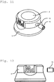
Fig. 11 die perspektivische Ansicht eines Außenadapters am Unterarm, -
Fig. 12 die Seitenansicht eines Außenadapters am Unterarm, -
Fig. 13 eine Gewindestange (Verbinder) in Rohrform im Schnitt, -
Fig. 14 eine Gewindestange (Verbinder) in perspektivischer Ansicht, -
Fig. 15 ein Schaft mit Gewindestange und Innenadapter, -
Fig. 16 ein Schaft mit der angedeuteten Beweglichkeit und unterschiedlicher Justierung, -
Fig. 17 ein Ellbogengelenk in perspektivischer Ansicht, -
Fig. 18 die Seitenansicht eines Ellbogengelenks, -
Fig. 19 die Seitenansicht eines Handgelenks, -
Fig. 20 die perspektivische Ansicht eines Handgelenks, -
Fig. 21 die Schnittdarstellung durch eine Gewindestange (Verbinder) in Rohrform mit innenliegender - kohlenstofffaserverstärktem Kunststoffschicht,
-
Fig. 22 die Schnittdarstellung eines Gelenkteiles mit einer Messinggewindehülse in der Bohrung für eine Sicherungsschraube und -
Fig. 23 eine komplette Armprothese mit Schaft, Adaptern, Gelenken, Verbindern und einer Handprothese. - Der erfindungsgemäße Schaft 1 besitzt am distalen Ende eine Ausbuchtung für die Aufnahme eines Innenadapters 4 mit einem Verbinder 3. Die in den
Figuren 1 bis 3 und 9 und 10 dargestellten Dummys 16 werden zur Herstellung der Ausbuchtungen am jeweiligen Schaft 1 benutzt und sind im Normalfall nicht Bestandteil des Schaftes 1 als Endprodukt. Es ist jedoch denkbar, dass diese Dummys 16 als Verstärkungselement 16 im Schaft 1 verbleiben. Dieses Verstärkungselement 16 oder Dummy 16, wird während des Tiefzieh- bzw. Gießvorganges in den Schaft 1 eingearbeitet und besitzt bereits eine Öffnung 2 für die spätere Aufnahme 2 einer Gewindestange 3 bzw. Verbinder 3. Die in denFiguren 1 bis 3 und 9 und 10 dargestellten Durchgangslöcher 17 besitzen eine wichtige Funktion bei der Herstellung des Schaftes 1. Der Dummy 16 wird mittels 2-Komponenten-Knetsilikon auf dem Schaft fixiert, auch die Durchgangslöcher 17 werden hierzu mit dem Knetsilikon ausgefüllt und die Oberfläche glatt verarbeitet. Wie bereits oben beschrieben, erfolgt dann der Tiefzieh- bzw. Gießvorgang. Die Öffnung 2 des Dummy 16 wird dann später frei gearbeitet und bietet die Aufnahme 2 für die Gewindestange 3. Innerhalb des Schaftes 1 wird dazu später der Innenadapter 4 bis zum Anschlag aufgeschraubt. In der Aufnahme 2 des Innenadapters 4 ist dafür ein Innengewinde vorgesehen, in denFiguren 4 bis 6 nicht dargestellt. Die Oberfläche des Innenadapters 4 in Richtung Schaft 1 ist der Oberfläche des Schaftes 1 angepasst. Außerhalb des Schaftes 1 ist auf dem Verbinder 3 eine Kontermutter 5 in Form eines Außenadapters 5 vorgesehen. Zur besseren Fixierung des Innenadapters 4 und des Außenadapters 5 am Schaft 1 ist einmal der Außenadapter 5 halbschalenförmig in Richtung Schaft 1 ausgebildet. Diese Halbschale 6 kann eine elastische Oberfläche besitzen, mit einem elastischen Überzug versehen sein oder elastische Teilflächen besitzen. Der Innenadapter 4 kann auf der Oberfläche in Richtung Schaft 1 ebenso gestaltet sein. Vorteilhaft besitzt er jedoch auf dieser Seite zum Schaft 1 eine Nut 10 mit einem darin eingelegten elastischen Ring 11. Dieser Ring 11 ragt etwas über die Oberfläche des Innenadapters 4 hinaus, wie inFigur 6 dargestellt. - Am anderen Ende des Verbinders 3, vom Schaft 1 aus gesehen, ist ein Ellbogengelenk 7 angeordnet. Das Ellenbogengelenk 7 besitzt, wie in
Figur 17 und 18 dargestellt, an beiden Enden ein Innengewinde für die Aufnahme je eines Verbinders 3, den Verbinder 3 vom Schaft 1 und einen Verbinder 3 zu einem Handgelenk 8. Das Handgelenk 8 besitzt, wie inFigur 19 und 20 dargestellt an einer Seite ein Innengewinde zur Aufnahme des Verbinders 3 vom Ellbogengelenk 7 und am anderen Ende des Handgelenks 8 einen Ansatz 18 mit einem Außengewinde für die Aufnahme einer Handprothese 19. - Die Verbindungen zwischen den Adaptern 4 und 5 zu den Verbindern 3 und der Gelenke 7 und 8 zu den Verbindern 3 werden vorteilhaft durch in die Bauteile Adapter 4 und 5 und Gelenke 7 und 8 eingearbeitete Bohrungen 13 und darin eingearbeitete Messinggewindehülsen 14 und durch entsprechende Sicherungsschrauben 15, vorzugsweise durch Innensechskantschrauben 15 gesichert. Diese Messinggewindehülsen 15 sichern eine lange Haltbarkeit gerade der sehr belasteten Gewinde bei eventuell notwendigen Nachjustierungen an der Armprothese. Diese Ausführungsart mit einer Messinggewindehülse 14 ist in
Figur 22 an einer Schnittdarstellung eines Gelenkteiles 9 dargestellt. - Alle Einzelteile der Armprothese bestehen aus Kunststoff. So auch die Verbinder 3 aus Vollmaterialstäben mit aufgearbeitetem Gewinde. Es hat sich jedoch als vorteilhaft erwiesen, dass die Verbinder 3 als Rohr ausgebildet sind und auf der Innenseite der Rohre eine Schicht 12 oder ein Rohr 12 aus kohlenstofffaserverstärktem Kunststoff aufgetragen bzw. eingearbeitet ist. Durch diese konstruktive Lösung erhöht sich die Stabilität und Flexibilität der Armprothese auch bei einer weiteren Minimierung des Materialeinsatzes.
- Es ist logisch, dass die beschriebene Lösung für eine komplette Armprothese auch reduziert auf eine Unterarmprothese anwendbar ist.
- Die Herstellung eines Schaftes 1 nach der erfindungsgemäßen konstruktiven Lösung für die Aufnahme eines Verbinders 3 mit einem Innenadapter 4 und einem Außenadapter 5 wird vorteilhaft mit folgenden Verfahrensschritten durchgeführt. Vom gesunden Arm werden die Maße aufgenommen, danach wird der Armstumpf mit Frischhaltefolie umwickelt und anschließend werden die Umfangsmaße des Armstumpfes aufgenommen. Weiterhin wird anschließend der Armstumpf mit Gipsbinden umwickelt und dieses Wickelmuster nach dem Aushärten vom Armstumpf abgenommen und mit Gips gefüllt. Nach dem Aushärten dieser Gipsfüllung wird diese Gipsform modelliert und ein Innenschaft, z. B. durch ein Tiefziehverfahren, erzeugt. Auf diesen Innenschaft wird ein Dummy 16 aufgesetzt und mittels Knetsilikon am Innenschaft verklebt und die Übergänge werden mit dem Knetsilikon ausgeglichen und die Durchgangslöcher 17 des Dummys 16 ausgefüllt. Anschließend erfolgt unter Nutzung des Innenschaftes mit dem aufgesetzten Dummy 16 das Tiefziehen und Entformen eines Schaftes 1. Nun erfolgt die Einarbeitung eines Lochs in den Schaft 1 am distalen Ende und die Einführung eines Verbinders 3 mit einem aufgeschraubten Innenadapter 4 durch das Loch des Schaftes 1, die Befestigung des Innenadapters 4 mit dem Verbinder 3 mittels eines Außenadapters 5 auf dem Verbinder 3 und somit die Aufnahme des Innenadapters 4 im Schaft 1 mit dem nach außen führenden Verbinder 3.
- Wie oben beschrieben, wird ähnlich eine Unterarmprothese hergestellt. Hierzu werden jedoch die Dummys 16 nach den
Figuren 9 und 10 verwendet. Alle Arbeitsschritte wie bei einer Oberarmprothese sind auch bei einer Unterarmprothese notwendig. -
- 1 -
- Schaft
- 2 -
- Öffnung, Aufnahme
- 3 -
- Gewindestange, Verbinder
- 4 -
- Innenadapter
- 5 -
- Kontermutter, Außenadapter
- 6 -
- Halbschale
- 7 -
- Ellbogengelenk
- 8 -
- Handgelenk
- 9 -
- Schnittdarstellung eines Gelenkteiles
- 10 -
- Nut
- 11 -
- elastischer Ring
- 12 -
- Schicht aus kohlenstofffaserverstärktem Kunststoff
- 13 -
- Bohrungen
- 14 -
- Messinggewindehülsen
- 15 -
- Sicherungsschrauben, Innensechskantschrauben
- 16 -
- Verstärkungselement, Dummy
- 17 -
- Durchgangslöcher
- 18 -
- Ansatz
- 19 -
- Handprothese
Claims (9)
- Armprothese in Leichtbauweise, bei hoher Stabilität und einem geringeren Gewicht gegenüber bisher bekannten Lösungen,
dadurch gekennzeichnet,
dass am distalen Ende eines an sich bekannten Schaftes (1) eine Ausbuchtung für die Aufnahme eines Innenadapters (4) mit einer Öffnung (2) als Aufnahme (2) für einen Verbinder (3) in Form einer Gewindestange (3) angeordnet ist und die Gewindestange (3) innerhalb des Schaftes (1) in dem auf der Gewindestange (3) aufgeschraubten Innenadapter (4) endet, die Gewindestange (3) durch ein Loch im Schaft (1) nach außen geführt ist und der Innenadapter (4) auf der Seite, die an der Schaftinnenseite anliegt, dem Schaft (1) um das Loch herum angepasst ist und auf der Gewindestange (3) außerhalb des Schaftes (1) eine Kontermutter (5) bzw. ein Außenadapter (5) angeordnet ist, dessen Seite zum Schaft (1) hin als Halbschale (6) ausgeführt und am anderen Ende des Verbinders (3) ein Ellbogengelenk (7) angeordnet ist, welches an beiden Enden ein Innengewinde für die Aufnahme je eines Verbinders (3), den Verbinder (3) vom Schaft (1) und einen Verbinder (3) zu einem Handgelenk (8), besitzt und das Handgelenk (8) an einer Seite ein Innengewinde zur Aufnahme des Verbinders (3) vom Ellbogengelenk (7) besitzt und am anderen Ende das Handgelenk (8) einen Ansatz (17) mit einem Außengewinde für die Aufnahme einer Handprothese (19) besitzt, wobei alle Einzelteile der Armprothese aus Kunststoff bestehen. - Armprothese nach Anspruch 1,
dadurch gekennzeichnet,
dass am distalen Ende des Schaftes (1) in einer zusätzlichen Ausbuchtung des Schaftes (1) um das Loch des Schaftes ein Verstärkungselement (16), ein Dummy (16) eingearbeitet ist. - Armprothese nach einem der vorhergehenden Ansprüche,
dadurch gekennzeichnet,
dass der Innenadapter (4) auf der Seite in Richtung Schaft (1) der Oberfläche des Schaftes (1) angepasst ist und auf der Oberfläche in Richtung Schaft (1) eine kreisförmige Nut (10) und darin eingelegt einen elastischen Ring (11) besitzt, der mit seiner Oberfläche über die Oberfläche des Innenadapters (4) hinausragt. - Armprothese nach einem der vorhergehenden Ansprüche,
dadurch gekennzeichnet,
dass der Außenadapter (5) auf der Seite in Richtung Schaft (1) die Form einer Halbschale (6) besitzt. - Armprothese nach einem der vorhergehenden Ansprüche,
dadurch gekennzeichnet,
dass die Oberfläche des Innenadapters (4) und des Außenadapters (5) in Richtung Schaft (1) elastisch ausgeführt ist oder einen elastischen Überzug oder elastische Flächen besitzt. - Armprothese nach einem der vorhergehenden Ansprüche,
dadurch gekennzeichnet,
dass die Verbinder (3) als Rohr ausgebildet sind und auf der Innenseite der Rohre eine Schicht (12) oder ein Rohr aus kohlenstofffaserverstärktem Kunststoff aufgetragen oder eingearbeitet ist. - Armprothese nach einem der vorhergehenden Ansprüche,
dadurch gekennzeichnet,
dass die Adapter (4 und 5) und die Gelenke (7 und 8) zu den Verbindern (3) mittels Sicherungsschrauben / Innensechskantschrauben (15) gesichert sind und in die dazu notwendigen Bohrungen (13) Messinggewindehülsen (14) eingearbeitet sind. - Verfahren zur Herstellung eines Armprothesenschaftes für die Aufnahme eines Verbinders mit Innen- und Außenadapter,
dadurch gekennzeichnet,
dass vom gesunden Arm die Maße aufgenommen werden, danach der Armstumpf mit Frischhaltefolie umwickelt wird und anschließend die Umfangsmaße des Armstumpfes aufgenommen werden, anschließend der Armstumpf mit Gipsbinden umwickelt wird und dieses Wickelmuster nach dem Aushärten vom Armstumpf abgenommen und mit Gips gefüllt wird, nach dem Aushärten dieser Gipsfüllung wird diese Gipsform modelliert und ein Innenschaft z. B. durch ein Tiefziehverfahren erzeugt, auf diesen Innenschaft wird ein Dummy aufgesetzt und mittels Knetsilikon werden die Übergänge ausgeglichen, die Durchgangslöcher (17) des Dummys (16) ausgefüllt und anschließend erfolgt unter Nutzung des Innenschaftes mit dem aufgesetzten Dummy (16) das Tiefziehen und Entformen eines Schaftes (1) und die Einarbeitung eines Lochs in den Schaft (1) am distalen Ende des Schaftes (1) und die Einführung eines Verbinders (3) mit einem aufgeschraubten Innenadapter (4) durch das Loch des Schaftes (1) und somit die Aufnahme des Innenadapters (4) im Schaft (1) mit nachfolgender Befestigung des Innenadapters (4) am Schaft (1) durch einen aufgeschraubten Außenadapter (5) auf den Verbinder (3), wobei für die Herstellung eines Oberarmschaftes die Dummys (16) nach den Figuren 1 bis 3 verwendet werden. - Verfahren zur Herstellung eines Unterarmprothesenschaftes für die Aufnahme eines Verbinders mit Innen- und Außenadapter,
dadurch gekennzeichnet,
dass die Arbeitsschritte gemäß Anspruch 8 auch identisch bei einer Unterarmprothesenherstellung erfolgen, hier jedoch die Dummys (16) nach den Figuren 9m und 10 verwendet werden.
Applications Claiming Priority (1)
| Application Number | Priority Date | Filing Date | Title |
|---|---|---|---|
| DE102020103112 | 2020-02-06 |
Publications (1)
| Publication Number | Publication Date |
|---|---|
| EP3861966A1 true EP3861966A1 (de) | 2021-08-11 |
Family
ID=71069798
Family Applications (1)
| Application Number | Title | Priority Date | Filing Date |
|---|---|---|---|
| EP20401036.7A Withdrawn EP3861966A1 (de) | 2020-02-06 | 2020-06-05 | Armprothese |
Country Status (2)
| Country | Link |
|---|---|
| EP (1) | EP3861966A1 (de) |
| DE (1) | DE102020112474A1 (de) |
Citations (13)
| Publication number | Priority date | Publication date | Assignee | Title |
|---|---|---|---|---|
| DE315888C (de) * | ||||
| FR1040394A (fr) * | 1951-08-08 | 1953-10-14 | Proteor Sa | Perfectionnements au montage, sur les cupules des bras artificiels, des accessoires nécessaires aux mutilés |
| DE1922619A1 (de) | 1969-05-03 | 1970-11-19 | Otto Bock Kg | Justierbares Verbindungselement zwischen Prothesenteilen |
| DE2711551C2 (de) | 1977-03-17 | 1983-11-17 | Chas. A. Blatchford & Sons Ltd., Basingstoke, Hampshire | Lasttragender Teil einer Bein- oder Armprothese und Verfahren zu seiner Herstellung |
| US5263990A (en) * | 1991-12-04 | 1993-11-23 | Handal Jady G | Prosthetic with bar reinforced shell |
| US5888232A (en) * | 1994-11-29 | 1999-03-30 | Taylor; Douglas A. | Ultralight modular quick-adjusting connector |
| US20020183859A1 (en) * | 2001-06-04 | 2002-12-05 | Houser Guy M. | Socket interface sleeve for a prosthetic device |
| US20050149202A1 (en) * | 2004-01-07 | 2005-07-07 | Schaffer Stephen P. | Liner with exterior coating for use with prosthetic devices |
| DE102006046927A1 (de) | 2006-09-29 | 2008-04-03 | Otto Bock Healthcare Ip Gmbh & Co. Kg | Prothese mit einem Schaft zur Aufnahme eines Amputationsstumpfes |
| DE202011000316U1 (de) | 2010-02-23 | 2011-10-27 | The Ohio Willow Wood Company | Prothetischer Liner auf Polymerbasis |
| DE102006046928B4 (de) | 2006-09-29 | 2012-03-08 | Otto Bock Healthcare Gmbh | Prothese mit einem Schaft zur Aufnahme eines Amputationsstumpfes |
| US20140277584A1 (en) * | 2013-03-14 | 2014-09-18 | Lim Innovations, Inc. | Modular prosthetic sockets and methods for making and using same |
| US20160278949A1 (en) * | 2011-04-08 | 2016-09-29 | Ifit Prosthetics, Llc | Modular prosthetic devices and prosthesis systems |
-
2020
- 2020-05-07 DE DE102020112474.0A patent/DE102020112474A1/de active Pending
- 2020-06-05 EP EP20401036.7A patent/EP3861966A1/de not_active Withdrawn
Patent Citations (13)
| Publication number | Priority date | Publication date | Assignee | Title |
|---|---|---|---|---|
| DE315888C (de) * | ||||
| FR1040394A (fr) * | 1951-08-08 | 1953-10-14 | Proteor Sa | Perfectionnements au montage, sur les cupules des bras artificiels, des accessoires nécessaires aux mutilés |
| DE1922619A1 (de) | 1969-05-03 | 1970-11-19 | Otto Bock Kg | Justierbares Verbindungselement zwischen Prothesenteilen |
| DE2711551C2 (de) | 1977-03-17 | 1983-11-17 | Chas. A. Blatchford & Sons Ltd., Basingstoke, Hampshire | Lasttragender Teil einer Bein- oder Armprothese und Verfahren zu seiner Herstellung |
| US5263990A (en) * | 1991-12-04 | 1993-11-23 | Handal Jady G | Prosthetic with bar reinforced shell |
| US5888232A (en) * | 1994-11-29 | 1999-03-30 | Taylor; Douglas A. | Ultralight modular quick-adjusting connector |
| US20020183859A1 (en) * | 2001-06-04 | 2002-12-05 | Houser Guy M. | Socket interface sleeve for a prosthetic device |
| US20050149202A1 (en) * | 2004-01-07 | 2005-07-07 | Schaffer Stephen P. | Liner with exterior coating for use with prosthetic devices |
| DE102006046927A1 (de) | 2006-09-29 | 2008-04-03 | Otto Bock Healthcare Ip Gmbh & Co. Kg | Prothese mit einem Schaft zur Aufnahme eines Amputationsstumpfes |
| DE102006046928B4 (de) | 2006-09-29 | 2012-03-08 | Otto Bock Healthcare Gmbh | Prothese mit einem Schaft zur Aufnahme eines Amputationsstumpfes |
| DE202011000316U1 (de) | 2010-02-23 | 2011-10-27 | The Ohio Willow Wood Company | Prothetischer Liner auf Polymerbasis |
| US20160278949A1 (en) * | 2011-04-08 | 2016-09-29 | Ifit Prosthetics, Llc | Modular prosthetic devices and prosthesis systems |
| US20140277584A1 (en) * | 2013-03-14 | 2014-09-18 | Lim Innovations, Inc. | Modular prosthetic sockets and methods for making and using same |
Also Published As
| Publication number | Publication date |
|---|---|
| DE102020112474A1 (de) | 2021-08-12 |
Similar Documents
| Publication | Publication Date | Title |
|---|---|---|
| EP1411872B1 (de) | Prothese | |
| DE4435497C1 (de) | Modulares Knochenimplantat mit Pfanne und Stiften | |
| DE69026079T2 (de) | Zahnimplantat | |
| DE2529669A1 (de) | Bandprothese, insbesondere kreuzbandprothese | |
| DE3787811T2 (de) | Beinprothese. | |
| EP3562442B1 (de) | Befestigungsanordnung einer prothesenhand an einem unterarmschaft und prothesensystem | |
| EP0619990B1 (de) | Bausatz für eine künstliche Gelenkspfanne, insbesondere eine Hüftgelenkspfanne | |
| DE2849588A1 (de) | Gelenkprothese | |
| DE2811331A1 (de) | Ellenbogengelenk in form einer endovollprothese | |
| DE2447772A1 (de) | Gelenk-endoprothese | |
| DE102010008382A1 (de) | Verfahren zum Crimpen bzw. Falten eines medizinischen Implantats an einer Einrichtung zum Verbringen oder Einführen desselben unter Einsatz von Zero-Pressure-Crimping sowie Einrichtungen | |
| DE19721703A1 (de) | Kathetersystem mit hoher Knickfestigkeit | |
| DE20221475U1 (de) | Befestigungsvorrichtung für eine Orthese oder eine Prothese | |
| EP3419566B1 (de) | Verfahren zum abformen eines amputationsstumpfes und abformhilfe für ein solches verfahren | |
| DE202011001354U1 (de) | Trampolin | |
| DE102018111442B4 (de) | Verfahren zum Herstellen einer orthopädietechnischen Einrichtung | |
| DE4136313C2 (de) | Äußere axiale Fixiervorrichtung | |
| WO2006076962A2 (de) | Kupplung zur formstabilen verbindung eines prothesenteils mit einem halteelement | |
| DE102020112474A1 (de) | Armprothese | |
| DE2711551C2 (de) | Lasttragender Teil einer Bein- oder Armprothese und Verfahren zu seiner Herstellung | |
| DE102012017213B3 (de) | Prothesenschaft | |
| EP1079771A1 (de) | Hülse für amputationsstümpfe | |
| DE19604458A1 (de) | Gelenkpfanne | |
| DE102019116417A1 (de) | Orthese mit einer ein bikondyläres Gelenk nachbildenden Gelenkeinrichtung und Gelenkeinrichtung | |
| DE29504291U1 (de) | Gelenkprothese |
Legal Events
| Date | Code | Title | Description |
|---|---|---|---|
| PUAI | Public reference made under article 153(3) epc to a published international application that has entered the european phase |
Free format text: ORIGINAL CODE: 0009012 |
|
| STAA | Information on the status of an ep patent application or granted ep patent |
Free format text: STATUS: THE APPLICATION HAS BEEN PUBLISHED |
|
| AK | Designated contracting states |
Kind code of ref document: A1 Designated state(s): AL AT BE BG CH CY CZ DE DK EE ES FI FR GB GR HR HU IE IS IT LI LT LU LV MC MK MT NL NO PL PT RO RS SE SI SK SM TR |
|
| STAA | Information on the status of an ep patent application or granted ep patent |
Free format text: STATUS: THE APPLICATION IS DEEMED TO BE WITHDRAWN |
|
| 18D | Application deemed to be withdrawn |
Effective date: 20220212 |