EP3861914A1 - Contact-type detection electrode and movable electric apparatus - Google Patents
Contact-type detection electrode and movable electric apparatus Download PDFInfo
- Publication number
- EP3861914A1 EP3861914A1 EP18939342.4A EP18939342A EP3861914A1 EP 3861914 A1 EP3861914 A1 EP 3861914A1 EP 18939342 A EP18939342 A EP 18939342A EP 3861914 A1 EP3861914 A1 EP 3861914A1
- Authority
- EP
- European Patent Office
- Prior art keywords
- electrical conductors
- contact
- type detection
- detection electrode
- support
- Prior art date
- Legal status (The legal status is an assumption and is not a legal conclusion. Google has not performed a legal analysis and makes no representation as to the accuracy of the status listed.)
- Granted
Links
Images


Classifications
-
- G—PHYSICS
- G01—MEASURING; TESTING
- G01N—INVESTIGATING OR ANALYSING MATERIALS BY DETERMINING THEIR CHEMICAL OR PHYSICAL PROPERTIES
- G01N27/00—Investigating or analysing materials by the use of electric, electrochemical, or magnetic means
- G01N27/02—Investigating or analysing materials by the use of electric, electrochemical, or magnetic means by investigating impedance
- G01N27/22—Investigating or analysing materials by the use of electric, electrochemical, or magnetic means by investigating impedance by investigating capacitance
- G01N27/226—Construction of measuring vessels; Electrodes therefor
-
- G—PHYSICS
- G01—MEASURING; TESTING
- G01N—INVESTIGATING OR ANALYSING MATERIALS BY DETERMINING THEIR CHEMICAL OR PHYSICAL PROPERTIES
- G01N27/00—Investigating or analysing materials by the use of electric, electrochemical, or magnetic means
- G01N27/02—Investigating or analysing materials by the use of electric, electrochemical, or magnetic means by investigating impedance
-
- A—HUMAN NECESSITIES
- A47—FURNITURE; DOMESTIC ARTICLES OR APPLIANCES; COFFEE MILLS; SPICE MILLS; SUCTION CLEANERS IN GENERAL
- A47L—DOMESTIC WASHING OR CLEANING; SUCTION CLEANERS IN GENERAL
- A47L11/00—Machines for cleaning floors, carpets, furniture, walls, or wall coverings
- A47L11/40—Parts or details of machines not provided for in groups A47L11/02 - A47L11/38, or not restricted to one of these groups, e.g. handles, arrangements of switches, skirts, buffers, levers
- A47L11/4077—Skirts or splash guards
-
- A—HUMAN NECESSITIES
- A47—FURNITURE; DOMESTIC ARTICLES OR APPLIANCES; COFFEE MILLS; SPICE MILLS; SUCTION CLEANERS IN GENERAL
- A47L—DOMESTIC WASHING OR CLEANING; SUCTION CLEANERS IN GENERAL
- A47L11/00—Machines for cleaning floors, carpets, furniture, walls, or wall coverings
- A47L11/24—Floor-sweeping machines, motor-driven
-
- A—HUMAN NECESSITIES
- A47—FURNITURE; DOMESTIC ARTICLES OR APPLIANCES; COFFEE MILLS; SPICE MILLS; SUCTION CLEANERS IN GENERAL
- A47L—DOMESTIC WASHING OR CLEANING; SUCTION CLEANERS IN GENERAL
- A47L11/00—Machines for cleaning floors, carpets, furniture, walls, or wall coverings
- A47L11/40—Parts or details of machines not provided for in groups A47L11/02 - A47L11/38, or not restricted to one of these groups, e.g. handles, arrangements of switches, skirts, buffers, levers
-
- A—HUMAN NECESSITIES
- A47—FURNITURE; DOMESTIC ARTICLES OR APPLIANCES; COFFEE MILLS; SPICE MILLS; SUCTION CLEANERS IN GENERAL
- A47L—DOMESTIC WASHING OR CLEANING; SUCTION CLEANERS IN GENERAL
- A47L11/00—Machines for cleaning floors, carpets, furniture, walls, or wall coverings
- A47L11/40—Parts or details of machines not provided for in groups A47L11/02 - A47L11/38, or not restricted to one of these groups, e.g. handles, arrangements of switches, skirts, buffers, levers
- A47L11/4002—Installations of electric equipment
-
- A—HUMAN NECESSITIES
- A47—FURNITURE; DOMESTIC ARTICLES OR APPLIANCES; COFFEE MILLS; SPICE MILLS; SUCTION CLEANERS IN GENERAL
- A47L—DOMESTIC WASHING OR CLEANING; SUCTION CLEANERS IN GENERAL
- A47L11/00—Machines for cleaning floors, carpets, furniture, walls, or wall coverings
- A47L11/40—Parts or details of machines not provided for in groups A47L11/02 - A47L11/38, or not restricted to one of these groups, e.g. handles, arrangements of switches, skirts, buffers, levers
- A47L11/4011—Regulation of the cleaning machine by electric means; Control systems and remote control systems therefor
-
- A—HUMAN NECESSITIES
- A47—FURNITURE; DOMESTIC ARTICLES OR APPLIANCES; COFFEE MILLS; SPICE MILLS; SUCTION CLEANERS IN GENERAL
- A47L—DOMESTIC WASHING OR CLEANING; SUCTION CLEANERS IN GENERAL
- A47L9/00—Details or accessories of suction cleaners, e.g. mechanical means for controlling the suction or for effecting pulsating action; Storing devices specially adapted to suction cleaners or parts thereof; Carrying-vehicles specially adapted for suction cleaners
- A47L9/28—Installation of the electric equipment, e.g. adaptation or attachment to the suction cleaner; Controlling suction cleaners by electric means
- A47L9/2805—Parameters or conditions being sensed
-
- A—HUMAN NECESSITIES
- A47—FURNITURE; DOMESTIC ARTICLES OR APPLIANCES; COFFEE MILLS; SPICE MILLS; SUCTION CLEANERS IN GENERAL
- A47L—DOMESTIC WASHING OR CLEANING; SUCTION CLEANERS IN GENERAL
- A47L9/00—Details or accessories of suction cleaners, e.g. mechanical means for controlling the suction or for effecting pulsating action; Storing devices specially adapted to suction cleaners or parts thereof; Carrying-vehicles specially adapted for suction cleaners
- A47L9/28—Installation of the electric equipment, e.g. adaptation or attachment to the suction cleaner; Controlling suction cleaners by electric means
- A47L9/2836—Installation of the electric equipment, e.g. adaptation or attachment to the suction cleaner; Controlling suction cleaners by electric means characterised by the parts which are controlled
- A47L9/2852—Elements for displacement of the vacuum cleaner or the accessories therefor, e.g. wheels, casters or nozzles
-
- G—PHYSICS
- G01—MEASURING; TESTING
- G01N—INVESTIGATING OR ANALYSING MATERIALS BY DETERMINING THEIR CHEMICAL OR PHYSICAL PROPERTIES
- G01N27/00—Investigating or analysing materials by the use of electric, electrochemical, or magnetic means
- G01N27/02—Investigating or analysing materials by the use of electric, electrochemical, or magnetic means by investigating impedance
- G01N27/04—Investigating or analysing materials by the use of electric, electrochemical, or magnetic means by investigating impedance by investigating resistance
-
- A—HUMAN NECESSITIES
- A47—FURNITURE; DOMESTIC ARTICLES OR APPLIANCES; COFFEE MILLS; SPICE MILLS; SUCTION CLEANERS IN GENERAL
- A47L—DOMESTIC WASHING OR CLEANING; SUCTION CLEANERS IN GENERAL
- A47L2201/00—Robotic cleaning machines, i.e. with automatic control of the travelling movement or the cleaning operation
-
- A—HUMAN NECESSITIES
- A47—FURNITURE; DOMESTIC ARTICLES OR APPLIANCES; COFFEE MILLS; SPICE MILLS; SUCTION CLEANERS IN GENERAL
- A47L—DOMESTIC WASHING OR CLEANING; SUCTION CLEANERS IN GENERAL
- A47L2201/00—Robotic cleaning machines, i.e. with automatic control of the travelling movement or the cleaning operation
- A47L2201/04—Automatic control of the travelling movement; Automatic obstacle detection
-
- A—HUMAN NECESSITIES
- A47—FURNITURE; DOMESTIC ARTICLES OR APPLIANCES; COFFEE MILLS; SPICE MILLS; SUCTION CLEANERS IN GENERAL
- A47L—DOMESTIC WASHING OR CLEANING; SUCTION CLEANERS IN GENERAL
- A47L2201/00—Robotic cleaning machines, i.e. with automatic control of the travelling movement or the cleaning operation
- A47L2201/06—Control of the cleaning action for autonomous devices; Automatic detection of the surface condition before, during or after cleaning
Definitions
- the present disclosure relates to the field of dirt detection technologies, and in particular to a contact-type detection electrode and a movable electric device.
- the main purpose of the present disclosure is to provide a contact-type detection electrode for detecting dispersible dirt.
- a contact-type detection electrode including:
- the plurality of electrical conductors is made of conductive plastic, metal, metal conductive particle mixture, graphene, polymer material, or a silica gel conductive strip.
- the support is arranged with a positive-electrode connection portion and a negative-electrode connection portion, a part of the plurality of electrical conductors are connected to the positive-electrode connection portion, and the rest part of the plurality of electrical conductors are connected to the negative-electrode connection portion.
- each of the plurality of electrical conductors has a fine hair-like structure.
- the support has a first side, and the plurality of the electrical conductors are configured to be spaced apart from each other along the first side.
- one of the plurality of electrical conductors connected to the negative-electrode connection portion is disposed separately between two of the plurality of electrical conductors connected to the positive-electrode connection portion.
- each of the plurality of electrical conductors comprises a protruding section protruding from the first side, and a distance between adjacent two of the plurality of electrical conductors is greater than a sum of lengths of the protruding sections of the adjacent two of the plurality of electrical conductors.
- each of the plurality of electrical conductors is arranged in the support, and an end of the each of the plurality of electrical conductors is exposed from an end surface of the first side.
- the positive-electrode connection portion and the negative-electrode connection portion are plug-in connectors.
- the support is flexible.
- the support is a flexible printed circuit board or a flexible insulator.
- the support has a first surface
- the plurality of electrical conductors are a plurality of metal sheets laid on the first surface
- the contact-type detection electrode further includes a detect-and-control circuit connected to the plurality of the electrical conductors; wherein the detect-and-control circuit is configured to provide positive electrical signals to a part of the plurality of electrical conductors and to provide negative electrical signals to the rest part of the plurality of electrical conductors; the detect-and-control circuit is further configured to determine whether dirt is detected based on amount of change in an electrical signal between one of the plurality of electrical conductors with a positive electrical signal and another one of the plurality of electrical conductors with a negative electrical signal.
- the amount of change in the electrical signal is the amount of change in resistance, capacitance, or impedance.
- the positive-electrode connection portion and the negative-electrode connection portion are magnetic contacts.
- the support is in a strip shape or an arc shape.
- the support is arranged with bristles.
- the bristles are arranged between adjacent two of the plurality of electrical conductors.
- the present disclosure provides a movable electronic device, including a contact-type detection electrode for detecting dispersible dirt; wherein the contact-type detection electrode includes a support, and a plurality of electrical conductors arranged on the support and being flexible.
- the movable electronic device is a sweeping robot.
- dispersible dirt may be detected by arranging a plurality of electrical conductors on the support to form a detection electrode.
- some of the electrical conductors are connected to positive electricity, and some of the electrical conductors are connected to negative electricity.
- a path will be formed through the dirt.
- the electrical signal between the electrical conductor connected to positive electricity and the electrical conductor connected to negative electricity will change compared with the electrical signal between the two conductors being unconnected. Therefore, whether dirt is detected may be determined based on the amount of change in the electrical signal.
- the user may be reminded to process or control the movable electric device to stop working in time, such that the dirt may be prevented from being spreaded to other places when adhered to the movable electric device, thereby solving the problem of expanding the polluted area.
- the electrical conductors are made of flexible material, thereby improving the detection accuracy and avoiding the abrasion of the electrode.
- first, second, etc. in present disclosure are for descriptive purposes only, and cannot be construed as indicating or implying their relative importance or implicitly indicating the number of technical features indicated.
- the features defined with “first” and “second” may include at least one of the features either explicitly or implicitly.
- the technical solutions between the various embodiments may be combined with each other, which must be based on the ability of a person skilled in the art to realize. When the combination of technical solutions contradicts or cannot be realized, it should be considered that the combination of such technical solutions does not exist, nor fall within the scope of the present disclosure.
- some embodiments of the present disclosure provides a contact-type detection electrode, applicable to a mobile electric device such as a sweeping robot, an electric toy, etc.
- the contact-type detection electrode is configured to detect dirt accurately through a detection method of contacting with dirt, thereby reminding a user or controlling the movable electric device to stop working. In this way, occurrence of situations such as spread of dirt and expanding of polluted area may be reduced.
- the contact-type detection electrode according to some embodiments of the present disclosure may also be applied to any other device or place for dirt detection, or the contact-type detection electrode may be made as a separate movable detection device which may continuously move in the room to detect dirt.
- the specific implementation structure of the contact-type detection electrode will be mainly described below.
- the contact-type detection electrode proposed in some embodiments of the present disclosure includes a support 100 and a plurality of electrical conductors 200.
- the plurality of electrical conductors 200 are disposed on the support 100.
- the support 100 may be made of an insulating material to reduce the possibility of short circuit among the electrical conductors 200.
- a contact part between each electrical conductor 200 and the support 100 may be insulated.
- the structure of one electrical conductor 200 may be a sheet which is laid on the support 100.
- the electrical conductor 200 may have a rod-shaped structure or a fine hair-like structure, and a certain length of the electrical conductor 200 is protruded from the support 100 or a part of the electrical conductor 200 is exposed from the support 100 to contact with dirt.
- the specific form of the electrical conductor 200 is not limited herein.
- the support 100 may be made of a rigid or flexible material, and the conductive conductors 200 may also be made of a rigid or flexible material, which is not limited herein.
- the number of the electrical conductors 200 may be two, three, or even more. Some of the electrical conductors 200 are configured to be connected to positive electricity, and some of the electrical conductors 200 are configured to be connected to negative electricity.
- the principle of the dirt detection of the contact-type detection electrode is: a detection circuit detects the amount of change in an electrical signal between an electrical conductor 200 connected to positive electricity and an electrical conductor 200 connected to negative electricity to determine whether dirt is detected. When the two electrical conductors 200 contact with the dirt, a path will be formed through the dirt. The electrical signal between the electrical conductor 200 connected to positive electricity and the electrical conductor 200 connected to negative electricity will change compared with the electrical signal between the two conductors being unconnected.
- dirt may be determined based on the amount of change in the electrical signal.
- the user may be reminded to process or control the movable electric device to stop working in time, such that the dirt may be prevented from being spreaded to other places when adhered to the movable electric device, thereby solving the problem of expanding the polluted area.
- the breeding of bacteria may be reduced, and the difficulty and cost of cleaning may be reduced, which brings convenience to people's lives. As such, conflicts between pet feeding and the use of mobile electric devices such as sweeping robots may be eliminated.
- the electrical conductors 200 are adopted with a flexible material. It can be understood that when the contact-type detection electrode is arranged on the movable electric device, if the electrical conductors 200 are made of a non-flexible material, it is necessary to maintain a certain distance between the electrical conductors 200 and the ground or a specific platform. In this way, when the movable electric device moves, the electrical conductors 200 do not produce resistance against the ground or the specific platform, thereby reducing the abrasion of the electrical conductors 200 due to contact with the ground or the specific platform.
- liquid dirt or extremely small-sized particulate dirt may be difficult to be detected by the non-flexible electrical conductors 200.
- the flexible electrical conductors 200 can directly contact the ground or the specific platform for detection.
- the liquid dirt and extremely small-sized particulate dirt on the ground or the specific platform may also be contacted by the electrical conductors 200 for detection.
- the friction is small, and no additional resistance is generated, therefore the electrical conductors 200 are not easily worn.
- the electrical conductors 200 may be made of conductive plastic, metal, metal conductive particle mixture, graphene, polymer material or silica gel conductive strip.
- the electrical conductors 200 made of these materials have both good conductivity and good flexibility.
- the metal may be copper, aluminum, etc., which has certain flexibility.
- the support 100 may be adopted with a flexible material structure, and the electrical conductors 200 may be laid on the support 100. The friction force of the electrical conductor 200 in contact with the ground may be thus reduced in virtue of the flexibility of the support 100.
- the support 100 has a first surface, and the plurality of electrical conductors 200 are a plurality of metal sheets laid on the first surface. The number of the metal sheets may be two.
- the metal sheets may be arranged close to each other and spaced apart to facilitate adhesion of dirt.
- the conductive plastic may be a material doped with conductive polyacetylene, or a functional polymer material that is processed by processing and molding methods of plastic after mixing resin as a substrate with a conductive additive or conductive fiber.
- the substrate may include: polycarbonate/acrylonitrile butadiene styrene (PC/ABS), PC, ABS, polyamide (PA), polypropylene (PPE), etc.
- the conductive fiber may be: nickel-plated carbon fiber, stainless steel fiber, etc.
- the material of the support 100 is not limited.
- the support 100 may be selected to be more flexible, ensuring that the electrical conductors 200 may produce less friction and resistance and when performing the detection work close to or in contact with the ground, such that the abrasion may be limited.
- the support 100 may be a flexible printed circuit board or a flexible insulator.
- the printed circuit board is simply referred to as a PCB.
- Polyimide may be applied as a base material of a flexible PCB, which has good flexibility and strong toughness.
- the thickness of the flexible PCB may be 70 ⁇ m, which is 1/100 of the thickness of a rigid PCB board, thereby reducing the volume and consumables.
- the electrical conductors 200 may be prepared by a dip coating method, a bar coating method, a spray coating method, an inkjet printing method, a spin coating method, a screen printing method, a gravure printing method, a blade coating method, an electro-spinning method, an electric deposition method, a vacuum suction filtration method, a drop casting method, an interface deposition method, an Langmuir Blodgett (LB) deposition method or a layer-by-layer self-assembly method.
- the manufacturing processes are simple and easy to implement.
- the support 100 may be arranged with a positive-electrode connection portion and a negative-electrode connection portion. Some of the electrical conductors 200 are connected to the positive-electrode connection portion, and others are connected to the negative-electrode connection portion.
- the positive-electrode connection portion and the negative-electrode connection portion may be terminals, contacts, or jacks, etc.
- the structure thereof is not limited, and only required to be conveniently connected to a circuit providing positive and negative electricity. The purpose of the embodiments is to avoid each electrical conductor 200 being separately connected to the circuit providing positive and negative electricity. It is convenient to connect the electrical conductors 200 by leading out two terminals via the positive-electrode connection portion and the negative-electrode connection portion.
- the positive-electrode connection portion and the negative-electrode connection portion are configured as plug-in connectors. In this way, the connection structure between the electrical conductors 200 and the circuit providing positive and negative electricity may be simplified, and it is convenient to install and replace electrodes.
- the positive-electrode connection portion and the negative-electrode connection portion are configured as magnetic contacts.
- the corresponding connection to the circuit providing positive and negative electricity is then achieved by means of magnetic adsorption.
- it is also convenient to install and replace electrodes. Compared with the plug-in connectors and other connection structures, the volume of the magnetic contacts may be less.
- the electrical conductors 200 have a fine hair-like structure.
- the support 100 has a first side, and the plurality of the electrical conductors 200 are spaced apart from each other along the first side.
- the fine hair-like structure of the electrical conductors 200 and the support 100 constitute a structure similar to a brush, which may be configured as a sweeping assembly 300 on the sweeping robot, or may be installed at a specific location to increase the effect of cleaning dust while achieving the detection of dirt.
- the arrangement of the electrical conductors 200 may be implemented in a positive and negative electrical staggered arrangement. Specifically, an electrical conductor 200 connected to the negative-electrode connection portion is disposed separately between two electrical conductors 200 connected to the positive-electrode connection portion. In the arrangement of the electrical conductors 200, as long as any two adjacent electrical conductors 200 contact with dirt and form a path through the dirt, a detection signal will be output to determine that the dirt is detected.
- the electrical conductors 200 may be disposed in the support 100, and an end of each electrical conductor 200 is exposed from an end surface of the first side. When the exposed end is in contact with dirt, a path is formed to achieve the detection of dirt. Or, an end of each electrical conductor 200 protrudes from the first side. That is, each electrical conductor 200 includes a protruding section 2001 protruding from the first side. When the protruding section 2001 is in contact with dirt, a path is formed to achieve the detection of dirt.
- the distance between two adjacent electrical conductors 200 is greater than the sum of lengths of the protruding sections 2001 of the two electrical conductors 200.
- bristles may also be arranged on the support 100 to clean dust.
- the bristles may be arranged between the two adjacent electrical conductors 200 to adhere dirt, such that the adjacent two electrical conductors 200 may easily form a path when contacting with dirt.
- the support 100 may be arranged in a strip shape or an arc shape for sweeping dust.
- the contact-type detection electrode may be made as an independent component to be further applied to various devices or places.
- the contact-type detection electrode further includes a detect-and-control circuit connected to the plurality of the electrical conductors 200.
- the detect-and-control circuit is configured to provide positive electrical signals to a part of the electrical conductors 200 and provide negative electrical signals to another part of the electrical conductors 200.
- the detect-and-control circuit is also configured to determine whether dirt is detected based on the amount of change in electrical signal between any electrical conductor 200 with a positive electrical signal and any electrical conductor 200 with a negative electrical signal.
- an electrical path is formed through the dirt.
- the electrical signal between the positively charged electrical conductor 200 and the negatively charged electrical conductor 200 will change compared with the electrical signal between the two conductors being unconnected.
- An appropriate comparison threshold may be configured to determine whether the dirt is detected based on the amount of change in the electrical signal.
- the user may be reminded to process or control the movable electric device to stop working in time, such that the dirt may be prevented from being spreaded to other places when adhered to the movable electric device, thereby solving the problem of expanding the polluted area.
- the amount of change in the electrical signal may be the amount of change in resistance, capacitance or impedance, etc.
- the detect-and-control circuit may correspond to a resistance detection circuit, a capacitance detection circuit, and an impedance detection circuit.
- the resistance may also be implemented in the form of conductivity, Of course, there are other implementation methods, which are not listed here in detail.
- detecting dirt is based on direct contact with dirt, which has high accuracy and strong practicability, and can be truly applied to the market.
- some embodiments of the present disclosure also provide a movable electric device, which may be a sweeping robot or an electric toy.
- the movable electric device includes the above-mentioned contact-type detection electrode, which will not be repeated here.
- the contact-type detection electrode may be arranged at a position with a high probability of contact with dirt, including a forward direction and a tail direction (when moving backwards) of a chassis of the movable electric device, not limited to specific positions such as a periphery of the chassis, the chassis, a periphery of wheels, a wheel fender, etc.
- a corresponding circuit may be additionally arranged to provide the positive and negative electrical signals to the electrical conductors 200 and provide a discrimination mechanism to detect dirt.
- the above embodiments with the detect-and-control circuit may also be applied directly.
Landscapes
- Chemical & Material Sciences (AREA)
- Chemical Kinetics & Catalysis (AREA)
- Electrochemistry (AREA)
- Physics & Mathematics (AREA)
- Health & Medical Sciences (AREA)
- Life Sciences & Earth Sciences (AREA)
- Analytical Chemistry (AREA)
- Biochemistry (AREA)
- General Health & Medical Sciences (AREA)
- General Physics & Mathematics (AREA)
- Immunology (AREA)
- Pathology (AREA)
- Engineering & Computer Science (AREA)
- Mechanical Engineering (AREA)
- Geophysics And Detection Of Objects (AREA)
- Investigating Or Analyzing Materials By The Use Of Electric Means (AREA)
Abstract
Description
- The present application claims priority of
Chinese Patent Application No. 201811337412.0 - The present disclosure relates to the field of dirt detection technologies, and in particular to a contact-type detection electrode and a movable electric device.
- With the development of robot technologies, many sweeping robots with various functions are introduced, which provide convenience to people's lives.
- However, current sweeping robots do not have dirt detection functions, such as detecting soup, pet feces and other objects with certain viscosity and diffusivity on the ground. When the sweeping robots of this type clean the ground, the sweeping robots will be thus adhered to the dirt and spread the dirt to the entire room, causing serious pollution to the room.
- The main purpose of the present disclosure is to provide a contact-type detection electrode for detecting dispersible dirt.
- In order to achieve the above purpose, the present disclosure provides a contact-type detection electrode including:
- a support; and
- a plurality of electrical conductors, arranged on the support and being flexible.
- In some embodiments, the plurality of electrical conductors is made of conductive plastic, metal, metal conductive particle mixture, graphene, polymer material, or a silica gel conductive strip.
- In some embodiments, the support is arranged with a positive-electrode connection portion and a negative-electrode connection portion, a part of the plurality of electrical conductors are connected to the positive-electrode connection portion, and the rest part of the plurality of electrical conductors are connected to the negative-electrode connection portion.
- In some embodiments, each of the plurality of electrical conductors has a fine hair-like structure.
- In some embodiments, the support has a first side, and the plurality of the electrical conductors are configured to be spaced apart from each other along the first side.
- In some embodiments, one of the plurality of electrical conductors connected to the negative-electrode connection portion is disposed separately between two of the plurality of electrical conductors connected to the positive-electrode connection portion.
- In some embodiments, each of the plurality of electrical conductors comprises a protruding section protruding from the first side, and a distance between adjacent two of the plurality of electrical conductors is greater than a sum of lengths of the protruding sections of the adjacent two of the plurality of electrical conductors.
- In some embodiments, each of the plurality of electrical conductors is arranged in the support, and an end of the each of the plurality of electrical conductors is exposed from an end surface of the first side.
- In some embodiments, the positive-electrode connection portion and the negative-electrode connection portion are plug-in connectors.
- In some embodiments, the support is flexible.
- In some embodiments, the support is a flexible printed circuit board or a flexible insulator.
- In some embodiments, the support has a first surface, and the plurality of electrical conductors are a plurality of metal sheets laid on the first surface.
- In some embodiments, the contact-type detection electrode further includes a detect-and-control circuit connected to the plurality of the electrical conductors;
wherein the detect-and-control circuit is configured to provide positive electrical signals to a part of the plurality of electrical conductors and to provide negative electrical signals to the rest part of the plurality of electrical conductors;
the detect-and-control circuit is further configured to determine whether dirt is detected based on amount of change in an electrical signal between one of the plurality of electrical conductors with a positive electrical signal and another one of the plurality of electrical conductors with a negative electrical signal. - In some embodiments, the amount of change in the electrical signal is the amount of change in resistance, capacitance, or impedance.
- In some embodiments, the positive-electrode connection portion and the negative-electrode connection portion are magnetic contacts.
- In some embodiments, the support is in a strip shape or an arc shape.
- In some embodiments, the support is arranged with bristles.
- In some embodiments, the bristles are arranged between adjacent two of the plurality of electrical conductors.
- In order to achieve the above purpose, the present disclosure provides a movable electronic device, including a contact-type detection electrode for detecting dispersible dirt; wherein the contact-type detection electrode includes a support, and a plurality of electrical conductors arranged on the support and being flexible.
- In some embodiments, the movable electronic device is a sweeping robot.
- In the technical solutions provided by the present disclosure, dispersible dirt (oil, soup, porridge, animal feces, etc.) may be detected by arranging a plurality of electrical conductors on the support to form a detection electrode. When the detection electrode working, some of the electrical conductors are connected to positive electricity, and some of the electrical conductors are connected to negative electricity. When two electrical conductors contact with dirt, a path will be formed through the dirt. The electrical signal between the electrical conductor connected to positive electricity and the electrical conductor connected to negative electricity will change compared with the electrical signal between the two conductors being unconnected. Therefore, whether dirt is detected may be determined based on the amount of change in the electrical signal. When it is determined that dirt is detected, the user may be reminded to process or control the movable electric device to stop working in time, such that the dirt may be prevented from being spreaded to other places when adhered to the movable electric device, thereby solving the problem of expanding the polluted area. Moreover, the electrical conductors are made of flexible material, thereby improving the detection accuracy and avoiding the abrasion of the electrode.
- In order to more clearly explain the embodiments of the present disclosure or the technical solutions in the prior art, the following will briefly introduce the drawings required in the description of the embodiments or the prior art. Obviously, the drawings in the following description are only some embodiments of the present disclosure. For a person skilled in the art, without paying any creative work, other drawings can be obtained according to the structures shown in these drawings.
-
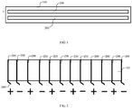
FIG. 1 is a structural schematic view of a contact-type detection electrode according to an embodiment of the present disclosure. -
FIG. 2 is a structural schematic view of a contact-type detection electrode according to another embodiment of the present disclosure. -
FIG 3 is a structural schematic view of a contact-type detection electrode according to further another embodiment of the present disclosure. -
FIG. 4 is another perspective view of the contact-type detection electrode shown inFIG. 3 . -
FIG. 5 is a structural schematic view of a movable electric device according to an embodiment of the present disclosure. -
FIG 6 is another perspective view of the movable electric device shown inFIG. 5 . - Implementation, functional characteristics and advantages of the present disclosure will be further described in conjunction with the embodiments and with reference to the drawings.
- The technical solutions in the embodiments of the present disclosure will be described clearly and completely with reference to the drawings in the embodiments of the present disclosure. Obviously, the described embodiments are only a part of the embodiments of the present disclosure, but not all the embodiments. Based on the embodiments in the present disclosure, all other embodiments obtained by a person skilled in the art without creative work fall within the scope of the present disclosure.
- It should be noted that all directional indicators (such as up, down, left, right, front, back, etc.) in the embodiments of the present disclosure are only to explain the relative positional relationship, movement conditions, etc. between components in a certain posture (as shown in the drawings). If the certain posture changes, the directional indicators change accordingly.
- In addition, the descriptions related to "first", "second", etc. in present disclosure are for descriptive purposes only, and cannot be construed as indicating or implying their relative importance or implicitly indicating the number of technical features indicated. Thus, the features defined with "first" and "second" may include at least one of the features either explicitly or implicitly. In addition, the technical solutions between the various embodiments may be combined with each other, which must be based on the ability of a person skilled in the art to realize. When the combination of technical solutions contradicts or cannot be realized, it should be considered that the combination of such technical solutions does not exist, nor fall within the scope of the present disclosure.
- People may encounter such troubles in their daily lives: when there is some viscous and dispersible dirt (oil, soup, porridge, animal feces) on the floor of the room that has not been cleaned in time, and a child in the house is playing an electric toy or a sweeping robot is sweeping the ground, the dirt may be then spreaded throughout the room, causing large-scale pollution and breeding a lot of bacteria. Especially for a family with a pet at home, when there is no one in the house and the sweeping robot is working, the pet feces may be then spreaded throughout the room. In this way, the difficulty and cost of cleaning is increased, and generated odors and bacteria will seriously affect the lives of family members. As such, a conflict may also exist between pet feeding and the use of a mobile electric device such as a sweeping robot.
- In view of the above problems, some embodiments of the present disclosure provides a contact-type detection electrode, applicable to a mobile electric device such as a sweeping robot, an electric toy, etc. The contact-type detection electrode is configured to detect dirt accurately through a detection method of contacting with dirt, thereby reminding a user or controlling the movable electric device to stop working. In this way, occurrence of situations such as spread of dirt and expanding of polluted area may be reduced. Of course, it should be noted that the contact-type detection electrode according to some embodiments of the present disclosure may also be applied to any other device or place for dirt detection, or the contact-type detection electrode may be made as a separate movable detection device which may continuously move in the room to detect dirt. The specific implementation structure of the contact-type detection electrode will be mainly described below.
- Referring to
FIGS. 1 to 4 , in some embodiments of the present disclosure, the contact-type detection electrode proposed in some embodiments of the present disclosure includes asupport 100 and a plurality ofelectrical conductors 200. The plurality ofelectrical conductors 200 are disposed on thesupport 100. Thesupport 100 may be made of an insulating material to reduce the possibility of short circuit among theelectrical conductors 200. Of course, a contact part between eachelectrical conductor 200 and thesupport 100 may be insulated. The structure of oneelectrical conductor 200 may be a sheet which is laid on thesupport 100. Or, theelectrical conductor 200 may have a rod-shaped structure or a fine hair-like structure, and a certain length of theelectrical conductor 200 is protruded from thesupport 100 or a part of theelectrical conductor 200 is exposed from thesupport 100 to contact with dirt. Of course, the specific form of theelectrical conductor 200 is not limited herein. - In some embodiments, the
support 100 may be made of a rigid or flexible material, and theconductive conductors 200 may also be made of a rigid or flexible material, which is not limited herein. - In some embodiments, the number of the
electrical conductors 200 may be two, three, or even more. Some of theelectrical conductors 200 are configured to be connected to positive electricity, and some of theelectrical conductors 200 are configured to be connected to negative electricity. The principle of the dirt detection of the contact-type detection electrode is: a detection circuit detects the amount of change in an electrical signal between anelectrical conductor 200 connected to positive electricity and anelectrical conductor 200 connected to negative electricity to determine whether dirt is detected. When the twoelectrical conductors 200 contact with the dirt, a path will be formed through the dirt. The electrical signal between theelectrical conductor 200 connected to positive electricity and theelectrical conductor 200 connected to negative electricity will change compared with the electrical signal between the two conductors being unconnected. Therefore, whether dirt is detected may be determined based on the amount of change in the electrical signal. When it is determined that the dirt is detected, the user may be reminded to process or control the movable electric device to stop working in time, such that the dirt may be prevented from being spreaded to other places when adhered to the movable electric device, thereby solving the problem of expanding the polluted area. Further, the breeding of bacteria may be reduced, and the difficulty and cost of cleaning may be reduced, which brings convenience to people's lives. As such, conflicts between pet feeding and the use of mobile electric devices such as sweeping robots may be eliminated. - Further, in order to improve the dirt detection ability and limit the abrasion of the
electrical conductors 200, theelectrical conductors 200 are adopted with a flexible material. It can be understood that when the contact-type detection electrode is arranged on the movable electric device, if theelectrical conductors 200 are made of a non-flexible material, it is necessary to maintain a certain distance between theelectrical conductors 200 and the ground or a specific platform. In this way, when the movable electric device moves, theelectrical conductors 200 do not produce resistance against the ground or the specific platform, thereby reducing the abrasion of theelectrical conductors 200 due to contact with the ground or the specific platform. However, in this case, liquid dirt or extremely small-sized particulate dirt may be difficult to be detected by the non-flexibleelectrical conductors 200. Whereas the flexibleelectrical conductors 200 can directly contact the ground or the specific platform for detection. In this way, the liquid dirt and extremely small-sized particulate dirt on the ground or the specific platform may also be contacted by theelectrical conductors 200 for detection. Moreover, when the flexibleelectrical conductors 200 are in contact with the ground or the specific platform, the friction is small, and no additional resistance is generated, therefore theelectrical conductors 200 are not easily worn. - The
electrical conductors 200 may be made of conductive plastic, metal, metal conductive particle mixture, graphene, polymer material or silica gel conductive strip. Theelectrical conductors 200 made of these materials have both good conductivity and good flexibility. The metal may be copper, aluminum, etc., which has certain flexibility. In this case, thesupport 100 may be adopted with a flexible material structure, and theelectrical conductors 200 may be laid on thesupport 100. The friction force of theelectrical conductor 200 in contact with the ground may be thus reduced in virtue of the flexibility of thesupport 100. Specifically, referring toFIG. 1 , thesupport 100 has a first surface, and the plurality ofelectrical conductors 200 are a plurality of metal sheets laid on the first surface. The number of the metal sheets may be two. The metal sheets may be arranged close to each other and spaced apart to facilitate adhesion of dirt. The conductive plastic may be a material doped with conductive polyacetylene, or a functional polymer material that is processed by processing and molding methods of plastic after mixing resin as a substrate with a conductive additive or conductive fiber. The substrate may include: polycarbonate/acrylonitrile butadiene styrene (PC/ABS), PC, ABS, polyamide (PA), polypropylene (PPE), etc. The conductive fiber may be: nickel-plated carbon fiber, stainless steel fiber, etc. - It should be noted that, when the
electrical conductors 200 are made of a material with better flexibility, the material of thesupport 100 is not limited. When theelectrical conductors 200 are made of a material with less flexibility, thesupport 100 may be selected to be more flexible, ensuring that theelectrical conductors 200 may produce less friction and resistance and when performing the detection work close to or in contact with the ground, such that the abrasion may be limited. Thesupport 100 may be a flexible printed circuit board or a flexible insulator. The printed circuit board is simply referred to as a PCB. Polyimide may be applied as a base material of a flexible PCB, which has good flexibility and strong toughness. The thickness of the flexible PCB may be 70µm, which is 1/100 of the thickness of a rigid PCB board, thereby reducing the volume and consumables. - The
electrical conductors 200 may be prepared by a dip coating method, a bar coating method, a spray coating method, an inkjet printing method, a spin coating method, a screen printing method, a gravure printing method, a blade coating method, an electro-spinning method, an electric deposition method, a vacuum suction filtration method, a drop casting method, an interface deposition method, an Langmuir Blodgett (LB) deposition method or a layer-by-layer self-assembly method. The manufacturing processes are simple and easy to implement. - Further, in order to facilitate the
electrical conductors 200 to be connected to the positive electricity and the negative electricity, thesupport 100 may be arranged with a positive-electrode connection portion and a negative-electrode connection portion. Some of theelectrical conductors 200 are connected to the positive-electrode connection portion, and others are connected to the negative-electrode connection portion. The positive-electrode connection portion and the negative-electrode connection portion may be terminals, contacts, or jacks, etc. The structure thereof is not limited, and only required to be conveniently connected to a circuit providing positive and negative electricity. The purpose of the embodiments is to avoid eachelectrical conductor 200 being separately connected to the circuit providing positive and negative electricity. It is convenient to connect theelectrical conductors 200 by leading out two terminals via the positive-electrode connection portion and the negative-electrode connection portion. - In some embodiments, the positive-electrode connection portion and the negative-electrode connection portion are configured as plug-in connectors. In this way, the connection structure between the
electrical conductors 200 and the circuit providing positive and negative electricity may be simplified, and it is convenient to install and replace electrodes. - In some embodiments, the positive-electrode connection portion and the negative-electrode connection portion are configured as magnetic contacts. The corresponding connection to the circuit providing positive and negative electricity is then achieved by means of magnetic adsorption. In this technical solution, it is also convenient to install and replace electrodes. Compared with the plug-in connectors and other connection structures, the volume of the magnetic contacts may be less.
- Referring to
FIGS. 2 ,5 and6 , in some embodiments, theelectrical conductors 200 have a fine hair-like structure. Thesupport 100 has a first side, and the plurality of theelectrical conductors 200 are spaced apart from each other along the first side. - In the embodiments, the fine hair-like structure of the
electrical conductors 200 and thesupport 100 constitute a structure similar to a brush, which may be configured as asweeping assembly 300 on the sweeping robot, or may be installed at a specific location to increase the effect of cleaning dust while achieving the detection of dirt. - In the embodiments, in order to improve the detection range, the arrangement of the
electrical conductors 200 may be implemented in a positive and negative electrical staggered arrangement. Specifically, anelectrical conductor 200 connected to the negative-electrode connection portion is disposed separately between twoelectrical conductors 200 connected to the positive-electrode connection portion. In the arrangement of theelectrical conductors 200, as long as any two adjacentelectrical conductors 200 contact with dirt and form a path through the dirt, a detection signal will be output to determine that the dirt is detected. - In the embodiments, referring to
FIG. 3 and FIG. 4 , theelectrical conductors 200 may be disposed in thesupport 100, and an end of eachelectrical conductor 200 is exposed from an end surface of the first side. When the exposed end is in contact with dirt, a path is formed to achieve the detection of dirt. Or, an end of eachelectrical conductor 200 protrudes from the first side. That is, eachelectrical conductor 200 includes a protrudingsection 2001 protruding from the first side. When the protrudingsection 2001 is in contact with dirt, a path is formed to achieve the detection of dirt. - When an end of each
electrical conductor 200 protrudes from the first side, in order to avoid short-circuiting between theelectrical conductors 200 corresponding to positive and negative electricity, which leads to a short circuit outputting an erroneous detection signal, the distance between two adjacentelectrical conductors 200 is greater than the sum of lengths of the protrudingsections 2001 of the twoelectrical conductors 200. - In the embodiments, bristles may also be arranged on the
support 100 to clean dust. In particular, the bristles may be arranged between the two adjacentelectrical conductors 200 to adhere dirt, such that the adjacent twoelectrical conductors 200 may easily form a path when contacting with dirt. Thesupport 100 may be arranged in a strip shape or an arc shape for sweeping dust. - Further, the contact-type detection electrode may be made as an independent component to be further applied to various devices or places. In further embodiments, the contact-type detection electrode further includes a detect-and-control circuit connected to the plurality of the
electrical conductors 200. - The detect-and-control circuit is configured to provide positive electrical signals to a part of the
electrical conductors 200 and provide negative electrical signals to another part of theelectrical conductors 200. - The detect-and-control circuit is also configured to determine whether dirt is detected based on the amount of change in electrical signal between any
electrical conductor 200 with a positive electrical signal and anyelectrical conductor 200 with a negative electrical signal. - When the positively charged
electrical conductor 200 and the negatively chargedelectrical conductor 200 are in contact with dirt, an electrical path is formed through the dirt. The electrical signal between the positively chargedelectrical conductor 200 and the negatively chargedelectrical conductor 200 will change compared with the electrical signal between the two conductors being unconnected. An appropriate comparison threshold may be configured to determine whether the dirt is detected based on the amount of change in the electrical signal. When it is determined that dirt is detected, the user may be reminded to process or control the movable electric device to stop working in time, such that the dirt may be prevented from being spreaded to other places when adhered to the movable electric device, thereby solving the problem of expanding the polluted area. - Specifically, the amount of change in the electrical signal may be the amount of change in resistance, capacitance or impedance, etc. Correspondingly, the detect-and-control circuit may correspond to a resistance detection circuit, a capacitance detection circuit, and an impedance detection circuit. The resistance may also be implemented in the form of conductivity, Of course, there are other implementation methods, which are not listed here in detail.
- In the above embodiments, it should be noted that in the contact-type detection electrode of the present disclosure, detecting dirt is based on direct contact with dirt, which has high accuracy and strong practicability, and can be truly applied to the market.
- In addition, referring to
FIGS. 1 to 6 , some embodiments of the present disclosure also provide a movable electric device, which may be a sweeping robot or an electric toy. The movable electric device includes the above-mentioned contact-type detection electrode, which will not be repeated here. - The contact-type detection electrode may be arranged at a position with a high probability of contact with dirt, including a forward direction and a tail direction (when moving backwards) of a chassis of the movable electric device, not limited to specific positions such as a periphery of the chassis, the chassis, a periphery of wheels, a wheel fender, etc.
- It should be noted that in the embodiments, a corresponding circuit may be additionally arranged to provide the positive and negative electrical signals to the
electrical conductors 200 and provide a discrimination mechanism to detect dirt. Of course, the above embodiments with the detect-and-control circuit may also be applied directly. - The above is only some embodiments of the present disclosure, and does not limit the scope of the present disclosure. Any equivalent structural transformations made by the description and drawings of the present disclosure under the inventive concept of the present disclosure, or applications directly/indirectly to other related technical fields are included in the scope of the present disclosure.
Claims (20)
- A contact-type detection electrode for detecting dispersible dirt, comprising:a support; anda plurality of electrical conductors, arranged on the support and being flexible.
- The contact-type detection electrode according to claim 1, wherein the plurality of electrical conductors is made of conductive plastic, metal, metal conductive particle mixture, graphene, polymer material, or a silica gel conductive strip.
- The contact-type detection electrode according to claim 1, wherein the support is arranged with a positive-electrode connection portion and a negative-electrode connection portion, a part of the plurality of electrical conductors are connected to the positive-electrode connection portion, and the rest part of the plurality of electrical conductors are connected to the negative-electrode connection portion.
- The contact-type detection electrode according to claim 3, wherein each of the plurality of electrical conductors has a fine hair-like structure.
- The contact-type detection electrode according to claim 4, wherein the support has a first side, and the plurality of the electrical conductors are configured to be spaced apart from each other along the first side.
- The contact-type detection electrode according to claim 5, wherein
one of the plurality of electrical conductors connected to the negative-electrode connection portion is disposed separately between two of the plurality of electrical conductors connected to the positive-electrode connection portion. - The contact-type detection electrode according to claim 6, wherein each of the plurality of electrical conductors comprises a protruding section protruding from the first side, and a distance between adjacent two of the plurality of electrical conductors is greater than a sum of lengths of the protruding sections of the adjacent two of the plurality of electrical conductors.
- The contact-type detection electrode according to claim 4, wherein each of the plurality of electrical conductors is arranged in the support, and an end of the each of the plurality of electrical conductors is exposed from an end surface of the first side.
- The contact-type detection electrode according to claim 3, wherein the positive-electrode connection portion and the negative-electrode connection portion are plug-in connectors.
- The contact-type detection electrode according to claim 1, wherein the support is flexible.
- The contact-type detection electrode according to claim 10, wherein the support is a flexible printed circuit board or a flexible insulator.
- The contact-type detection electrode according to claim 10, wherein the support has a first surface, and the plurality of electrical conductors are a plurality of metal sheets laid on the first surface.
- The contact-type detection electrode according to of claim 1, further comprising a detect-and-control circuit connected to the plurality of the electrical conductors;
wherein the detect-and-control circuit is configured to provide positive electrical signals to a part of the plurality of electrical conductors and to provide negative electrical signals to the rest part of the plurality of electrical conductors;
the detect-and-control circuit is further configured to determine whether dirt is detected based on amount of change in an electrical signal between one of the plurality of electrical conductors with a positive electrical signal and another one of the plurality of electrical conductors with a negative electrical signal. - The contact-type detection electrode according to of claim 13, wherein the amount of change in the electrical signal is the amount of change in resistance, capacitance, or impedance.
- The contact-type detection electrode according to of claim 3, wherein the positive-electrode connection portion and the negative-electrode connection portion are magnetic contacts.
- The contact-type detection electrode according to claim 1, wherein the support is in a strip shape or an arc shape.
- The contact-type detection electrode according to claim 1, wherein the support is arranged with bristles.
- The contact-type detection electrode according to of claim 17, wherein the bristles are arranged between adjacent two of the plurality of electrical conductors.
- A movable electronic device, comprising a contact-type detection electrode for detecting dispersible dirt, wherein the contact-type detection electrode comprises:a support; anda plurality of electrical conductors, arranged on the support and being flexible.
- The movable electronic device according to of claim 19, being a sweeping robot.
Applications Claiming Priority (2)
| Application Number | Priority Date | Filing Date | Title |
|---|---|---|---|
| CN201811338412.0A CN111175350A (en) | 2018-11-09 | 2018-11-09 | Contact type detection electrode and movable electric device |
| PCT/CN2018/122652 WO2020093554A1 (en) | 2018-11-09 | 2018-12-21 | Contact-type detection electrode and movable electric apparatus |
Publications (3)
| Publication Number | Publication Date |
|---|---|
| EP3861914A1 true EP3861914A1 (en) | 2021-08-11 |
| EP3861914A4 EP3861914A4 (en) | 2021-12-08 |
| EP3861914B1 EP3861914B1 (en) | 2024-02-28 |
Family
ID=70611465
Family Applications (1)
| Application Number | Title | Priority Date | Filing Date |
|---|---|---|---|
| EP18939342.4A Active EP3861914B1 (en) | 2018-11-09 | 2018-12-21 | Contact-type detection electrode and movable electric apparatus |
Country Status (6)
| Country | Link |
|---|---|
| US (1) | US11921072B2 (en) |
| EP (1) | EP3861914B1 (en) |
| JP (1) | JP7176820B2 (en) |
| KR (1) | KR102549450B1 (en) |
| CN (1) | CN111175350A (en) |
| WO (1) | WO2020093554A1 (en) |
Families Citing this family (1)
| Publication number | Priority date | Publication date | Assignee | Title |
|---|---|---|---|---|
| CN114965658A (en) * | 2021-02-26 | 2022-08-30 | 广东美的白色家电技术创新中心有限公司 | Test method for soluble sugar content in food |
Family Cites Families (26)
| Publication number | Priority date | Publication date | Assignee | Title |
|---|---|---|---|---|
| JPH0330745A (en) * | 1989-06-28 | 1991-02-08 | Matsushita Electric Ind Co Ltd | Dishwasher |
| US5608944A (en) * | 1995-06-05 | 1997-03-11 | The Hoover Company | Vacuum cleaner with dirt detection |
| DE102007038980B4 (en) * | 2007-08-17 | 2010-08-26 | Siemens Ag | Detector module, radiation detector and radiation detector |
| CN102106713A (en) * | 2009-12-29 | 2011-06-29 | 财团法人工业技术研究院 | Water removal system and water removal method |
| KR101302149B1 (en) * | 2011-08-18 | 2013-08-30 | 이상열 | Obstacle detecting apparatus for robot cleaner and robot cleaner having the same |
| KR101960816B1 (en) | 2011-12-22 | 2019-03-22 | 삼성전자주식회사 | Cleaning system |
| KR101480752B1 (en) * | 2012-03-30 | 2015-01-09 | 한국과학기술원 | Apparatus for measuring surface shape |
| KR101495191B1 (en) | 2013-10-21 | 2015-02-24 | 엘지전자 주식회사 | Robot cleaner and method for sensing dust of the same |
| GB201420918D0 (en) * | 2014-11-25 | 2015-01-07 | Rolls Royce Plc | Cleaning robot |
| US10874559B2 (en) * | 2014-12-11 | 2020-12-29 | Essity Hygiene And Health Aktiebolag | Impedance sensors for detecting and monitoring moisture in absorbent articles |
| WO2017031365A1 (en) * | 2015-08-18 | 2017-02-23 | Nilfisk, Inc. | Mobile robotic cleaner |
| CN105628742A (en) * | 2016-03-18 | 2016-06-01 | 太仓华平电子科技有限公司 | Multiple section connection type probe |
| TWI653964B (en) * | 2016-05-17 | 2019-03-21 | Lg Electronics Inc. | Mobile robot and its control method |
| CN107913030A (en) | 2016-10-06 | 2018-04-17 | 日立空调·家用电器株式会社 | Self walking electric dust catcher |
| CN106333631B (en) * | 2016-11-11 | 2022-03-08 | 北京地平线机器人技术研发有限公司 | Movable cleaning device and control method thereof |
| CN206403711U (en) | 2016-11-11 | 2017-08-15 | 北京地平线机器人技术研发有限公司 | Removable cleaning equipment |
| CN106524886A (en) | 2016-11-25 | 2017-03-22 | 张强 | Collision position detection device and system, and detection method |
| CN206388311U (en) * | 2017-01-23 | 2017-08-08 | 无锡职业技术学院 | rain alarm |
| CN207400702U (en) * | 2017-04-11 | 2018-05-25 | 李晓宇 | A kind of Intelligent robot for sweeping floor |
| CN207881914U (en) * | 2017-11-28 | 2018-09-18 | 歌尔科技有限公司 | A kind of fluid seepage detection circuit |
| CN108286934B (en) * | 2018-04-09 | 2020-01-31 | 哈尔滨工程大学 | A device for multi-point real-time measurement of wall liquid film thickness |
| CN108742333A (en) * | 2018-05-30 | 2018-11-06 | 上海与德通讯技术有限公司 | A kind of cleaning method and robot |
| KR102556375B1 (en) | 2018-11-09 | 2023-07-18 | 광둥 미디어 화이트 홈 어플라이언스 테크놀로지 이노베이션 센터 컴퍼니 리미티드 | cleaning robot |
| EP3858211B1 (en) | 2018-11-09 | 2025-03-12 | Guangdong Midea White Home Appliance Technology Innovation Center Co., Ltd. | Movable electronic apparatus |
| US11937751B2 (en) * | 2018-11-09 | 2024-03-26 | Guangdong Midea White Home Appliance Technology Innovation Center Co., Ltd. | Movable electric device |
| US11122951B2 (en) * | 2018-12-31 | 2021-09-21 | Irobot Corporation | Electrical connection for robot vacuum lid |
-
2018
- 2018-11-09 CN CN201811338412.0A patent/CN111175350A/en active Pending
- 2018-12-21 KR KR1020217013511A patent/KR102549450B1/en active Active
- 2018-12-21 US US17/290,243 patent/US11921072B2/en active Active
- 2018-12-21 JP JP2021523232A patent/JP7176820B2/en active Active
- 2018-12-21 WO PCT/CN2018/122652 patent/WO2020093554A1/en not_active Ceased
- 2018-12-21 EP EP18939342.4A patent/EP3861914B1/en active Active
Also Published As
| Publication number | Publication date |
|---|---|
| CN111175350A (en) | 2020-05-19 |
| KR20210069706A (en) | 2021-06-11 |
| US20220018794A1 (en) | 2022-01-20 |
| KR102549450B1 (en) | 2023-06-30 |
| WO2020093554A1 (en) | 2020-05-14 |
| JP2022506074A (en) | 2022-01-17 |
| EP3861914B1 (en) | 2024-02-28 |
| JP7176820B2 (en) | 2022-11-22 |
| US11921072B2 (en) | 2024-03-05 |
| EP3861914A4 (en) | 2021-12-08 |
Similar Documents
| Publication | Publication Date | Title |
|---|---|---|
| CN1183435C (en) | Coordinate input device | |
| EP3240120A3 (en) | Electrical connector assembly | |
| US11921072B2 (en) | Contact-type detection electrode and movable electric device | |
| WO2008096639A1 (en) | Touch switch structure | |
| TW201328104A (en) | Wireless charging device | |
| CN201716596U (en) | Obstacle avoidance mechanism of cleaning robot | |
| CN109257871A (en) | Flexible circuit board and mobile terminal | |
| CN108762580A (en) | Show equipment, touch sensing and preparation method thereof | |
| CN114571501B (en) | Electronic skin, proximity sensing method, mechanical arm and robot | |
| FR2833292B1 (en) | SYSTEM FOR DETECTING THE PRESENCE OF A USER, PARTICULARLY FOR A MOTOR VEHICLE | |
| JP2015032285A (en) | Stylus pen used for touch panel | |
| CN204720592U (en) | Wall hanging frame assembly and line sandwiched type connector thereof | |
| CN104716470B (en) | Plug connector | |
| EP2661162A3 (en) | Equipment provided with one or more plug-in units | |
| CN114649878B (en) | A wireless charging device and positioning method | |
| CN202085384U (en) | Electrostatic impedor | |
| CN1371306A (en) | air purifier | |
| CN209266674U (en) | A kind of automobile right angle single needle HSD pin connector | |
| CN208238721U (en) | A kind of charging testing agency | |
| CN203387770U (en) | Antistatic protection device, circuit board and electronic device | |
| CN203027605U (en) | Circuit board provided with built-in type resistor | |
| CN216488608U (en) | Vertical SMT type electronic connector | |
| CN204538370U (en) | Improved grounding structure for electrical connectors | |
| CN213184827U (en) | Shielding mechanism | |
| CN210776616U (en) | Spaced touch device and electronic equipment |
Legal Events
| Date | Code | Title | Description |
|---|---|---|---|
| STAA | Information on the status of an ep patent application or granted ep patent |
Free format text: STATUS: THE INTERNATIONAL PUBLICATION HAS BEEN MADE |
|
| PUAI | Public reference made under article 153(3) epc to a published international application that has entered the european phase |
Free format text: ORIGINAL CODE: 0009012 |
|
| STAA | Information on the status of an ep patent application or granted ep patent |
Free format text: STATUS: REQUEST FOR EXAMINATION WAS MADE |
|
| 17P | Request for examination filed |
Effective date: 20210504 |
|
| AK | Designated contracting states |
Kind code of ref document: A1 Designated state(s): AL AT BE BG CH CY CZ DE DK EE ES FI FR GB GR HR HU IE IS IT LI LT LU LV MC MK MT NL NO PL PT RO RS SE SI SK SM TR |
|
| A4 | Supplementary search report drawn up and despatched |
Effective date: 20211109 |
|
| RIC1 | Information provided on ipc code assigned before grant |
Ipc: G01N 27/04 20060101ALI20211103BHEP Ipc: G01N 27/02 20060101ALI20211103BHEP Ipc: A47L 11/40 20060101ALI20211103BHEP Ipc: A47L 11/24 20060101AFI20211103BHEP |
|
| DAV | Request for validation of the european patent (deleted) | ||
| DAX | Request for extension of the european patent (deleted) | ||
| STAA | Information on the status of an ep patent application or granted ep patent |
Free format text: STATUS: EXAMINATION IS IN PROGRESS |
|
| 17Q | First examination report despatched |
Effective date: 20220714 |
|
| GRAP | Despatch of communication of intention to grant a patent |
Free format text: ORIGINAL CODE: EPIDOSNIGR1 |
|
| STAA | Information on the status of an ep patent application or granted ep patent |
Free format text: STATUS: GRANT OF PATENT IS INTENDED |
|
| INTG | Intention to grant announced |
Effective date: 20231005 |
|
| GRAS | Grant fee paid |
Free format text: ORIGINAL CODE: EPIDOSNIGR3 |
|
| GRAA | (expected) grant |
Free format text: ORIGINAL CODE: 0009210 |
|
| STAA | Information on the status of an ep patent application or granted ep patent |
Free format text: STATUS: THE PATENT HAS BEEN GRANTED |
|
| AK | Designated contracting states |
Kind code of ref document: B1 Designated state(s): AL AT BE BG CH CY CZ DE DK EE ES FI FR GB GR HR HU IE IS IT LI LT LU LV MC MK MT NL NO PL PT RO RS SE SI SK SM TR |
|
| REG | Reference to a national code |
Ref country code: GB Ref legal event code: FG4D |
|
| REG | Reference to a national code |
Ref country code: CH Ref legal event code: EP |
|
| REG | Reference to a national code |
Ref country code: DE Ref legal event code: R096 Ref document number: 602018066071 Country of ref document: DE |
|
| REG | Reference to a national code |
Ref country code: IE Ref legal event code: FG4D |
|
| REG | Reference to a national code |
Ref country code: LT Ref legal event code: MG9D |
|
| P01 | Opt-out of the competence of the unified patent court (upc) registered |
Effective date: 20240520 |
|
| PG25 | Lapsed in a contracting state [announced via postgrant information from national office to epo] |
Ref country code: IS Free format text: LAPSE BECAUSE OF FAILURE TO SUBMIT A TRANSLATION OF THE DESCRIPTION OR TO PAY THE FEE WITHIN THE PRESCRIBED TIME-LIMIT Effective date: 20240628 |
|
| REG | Reference to a national code |
Ref country code: NL Ref legal event code: MP Effective date: 20240228 |
|
| PG25 | Lapsed in a contracting state [announced via postgrant information from national office to epo] |
Ref country code: LT Free format text: LAPSE BECAUSE OF FAILURE TO SUBMIT A TRANSLATION OF THE DESCRIPTION OR TO PAY THE FEE WITHIN THE PRESCRIBED TIME-LIMIT Effective date: 20240228 |
|
| PG25 | Lapsed in a contracting state [announced via postgrant information from national office to epo] |
Ref country code: GR Free format text: LAPSE BECAUSE OF FAILURE TO SUBMIT A TRANSLATION OF THE DESCRIPTION OR TO PAY THE FEE WITHIN THE PRESCRIBED TIME-LIMIT Effective date: 20240529 |
|
| PG25 | Lapsed in a contracting state [announced via postgrant information from national office to epo] |
Ref country code: HR Free format text: LAPSE BECAUSE OF FAILURE TO SUBMIT A TRANSLATION OF THE DESCRIPTION OR TO PAY THE FEE WITHIN THE PRESCRIBED TIME-LIMIT Effective date: 20240228 Ref country code: RS Free format text: LAPSE BECAUSE OF FAILURE TO SUBMIT A TRANSLATION OF THE DESCRIPTION OR TO PAY THE FEE WITHIN THE PRESCRIBED TIME-LIMIT Effective date: 20240528 Ref country code: NL Free format text: LAPSE BECAUSE OF FAILURE TO SUBMIT A TRANSLATION OF THE DESCRIPTION OR TO PAY THE FEE WITHIN THE PRESCRIBED TIME-LIMIT Effective date: 20240228 |
|
| PG25 | Lapsed in a contracting state [announced via postgrant information from national office to epo] |
Ref country code: ES Free format text: LAPSE BECAUSE OF FAILURE TO SUBMIT A TRANSLATION OF THE DESCRIPTION OR TO PAY THE FEE WITHIN THE PRESCRIBED TIME-LIMIT Effective date: 20240228 |
|
| PG25 | Lapsed in a contracting state [announced via postgrant information from national office to epo] |
Ref country code: RS Free format text: LAPSE BECAUSE OF FAILURE TO SUBMIT A TRANSLATION OF THE DESCRIPTION OR TO PAY THE FEE WITHIN THE PRESCRIBED TIME-LIMIT Effective date: 20240528 Ref country code: NO Free format text: LAPSE BECAUSE OF FAILURE TO SUBMIT A TRANSLATION OF THE DESCRIPTION OR TO PAY THE FEE WITHIN THE PRESCRIBED TIME-LIMIT Effective date: 20240528 Ref country code: NL Free format text: LAPSE BECAUSE OF FAILURE TO SUBMIT A TRANSLATION OF THE DESCRIPTION OR TO PAY THE FEE WITHIN THE PRESCRIBED TIME-LIMIT Effective date: 20240228 Ref country code: LT Free format text: LAPSE BECAUSE OF FAILURE TO SUBMIT A TRANSLATION OF THE DESCRIPTION OR TO PAY THE FEE WITHIN THE PRESCRIBED TIME-LIMIT Effective date: 20240228 Ref country code: IS Free format text: LAPSE BECAUSE OF FAILURE TO SUBMIT A TRANSLATION OF THE DESCRIPTION OR TO PAY THE FEE WITHIN THE PRESCRIBED TIME-LIMIT Effective date: 20240628 Ref country code: HR Free format text: LAPSE BECAUSE OF FAILURE TO SUBMIT A TRANSLATION OF THE DESCRIPTION OR TO PAY THE FEE WITHIN THE PRESCRIBED TIME-LIMIT Effective date: 20240228 Ref country code: GR Free format text: LAPSE BECAUSE OF FAILURE TO SUBMIT A TRANSLATION OF THE DESCRIPTION OR TO PAY THE FEE WITHIN THE PRESCRIBED TIME-LIMIT Effective date: 20240529 Ref country code: FI Free format text: LAPSE BECAUSE OF FAILURE TO SUBMIT A TRANSLATION OF THE DESCRIPTION OR TO PAY THE FEE WITHIN THE PRESCRIBED TIME-LIMIT Effective date: 20240228 Ref country code: ES Free format text: LAPSE BECAUSE OF FAILURE TO SUBMIT A TRANSLATION OF THE DESCRIPTION OR TO PAY THE FEE WITHIN THE PRESCRIBED TIME-LIMIT Effective date: 20240228 Ref country code: BG Free format text: LAPSE BECAUSE OF FAILURE TO SUBMIT A TRANSLATION OF THE DESCRIPTION OR TO PAY THE FEE WITHIN THE PRESCRIBED TIME-LIMIT Effective date: 20240228 |
|
| PG25 | Lapsed in a contracting state [announced via postgrant information from national office to epo] |
Ref country code: PL Free format text: LAPSE BECAUSE OF FAILURE TO SUBMIT A TRANSLATION OF THE DESCRIPTION OR TO PAY THE FEE WITHIN THE PRESCRIBED TIME-LIMIT Effective date: 20240228 Ref country code: PT Free format text: LAPSE BECAUSE OF FAILURE TO SUBMIT A TRANSLATION OF THE DESCRIPTION OR TO PAY THE FEE WITHIN THE PRESCRIBED TIME-LIMIT Effective date: 20240628 |
|
| REG | Reference to a national code |
Ref country code: AT Ref legal event code: MK05 Ref document number: 1660385 Country of ref document: AT Kind code of ref document: T Effective date: 20240228 |
|
| PG25 | Lapsed in a contracting state [announced via postgrant information from national office to epo] |
Ref country code: SE Free format text: LAPSE BECAUSE OF FAILURE TO SUBMIT A TRANSLATION OF THE DESCRIPTION OR TO PAY THE FEE WITHIN THE PRESCRIBED TIME-LIMIT Effective date: 20240228 Ref country code: PT Free format text: LAPSE BECAUSE OF FAILURE TO SUBMIT A TRANSLATION OF THE DESCRIPTION OR TO PAY THE FEE WITHIN THE PRESCRIBED TIME-LIMIT Effective date: 20240628 Ref country code: PL Free format text: LAPSE BECAUSE OF FAILURE TO SUBMIT A TRANSLATION OF THE DESCRIPTION OR TO PAY THE FEE WITHIN THE PRESCRIBED TIME-LIMIT Effective date: 20240228 Ref country code: LV Free format text: LAPSE BECAUSE OF FAILURE TO SUBMIT A TRANSLATION OF THE DESCRIPTION OR TO PAY THE FEE WITHIN THE PRESCRIBED TIME-LIMIT Effective date: 20240228 |
|
| PG25 | Lapsed in a contracting state [announced via postgrant information from national office to epo] |
Ref country code: DK Free format text: LAPSE BECAUSE OF FAILURE TO SUBMIT A TRANSLATION OF THE DESCRIPTION OR TO PAY THE FEE WITHIN THE PRESCRIBED TIME-LIMIT Effective date: 20240228 |
|
| PG25 | Lapsed in a contracting state [announced via postgrant information from national office to epo] |
Ref country code: SM Free format text: LAPSE BECAUSE OF FAILURE TO SUBMIT A TRANSLATION OF THE DESCRIPTION OR TO PAY THE FEE WITHIN THE PRESCRIBED TIME-LIMIT Effective date: 20240228 |
|
| PG25 | Lapsed in a contracting state [announced via postgrant information from national office to epo] |
Ref country code: CZ Free format text: LAPSE BECAUSE OF FAILURE TO SUBMIT A TRANSLATION OF THE DESCRIPTION OR TO PAY THE FEE WITHIN THE PRESCRIBED TIME-LIMIT Effective date: 20240228 Ref country code: EE Free format text: LAPSE BECAUSE OF FAILURE TO SUBMIT A TRANSLATION OF THE DESCRIPTION OR TO PAY THE FEE WITHIN THE PRESCRIBED TIME-LIMIT Effective date: 20240228 |
|
| PG25 | Lapsed in a contracting state [announced via postgrant information from national office to epo] |
Ref country code: AT Free format text: LAPSE BECAUSE OF FAILURE TO SUBMIT A TRANSLATION OF THE DESCRIPTION OR TO PAY THE FEE WITHIN THE PRESCRIBED TIME-LIMIT Effective date: 20240228 |
|
| PG25 | Lapsed in a contracting state [announced via postgrant information from national office to epo] |
Ref country code: SK Free format text: LAPSE BECAUSE OF FAILURE TO SUBMIT A TRANSLATION OF THE DESCRIPTION OR TO PAY THE FEE WITHIN THE PRESCRIBED TIME-LIMIT Effective date: 20240228 |
|
| PG25 | Lapsed in a contracting state [announced via postgrant information from national office to epo] |
Ref country code: SM Free format text: LAPSE BECAUSE OF FAILURE TO SUBMIT A TRANSLATION OF THE DESCRIPTION OR TO PAY THE FEE WITHIN THE PRESCRIBED TIME-LIMIT Effective date: 20240228 Ref country code: SK Free format text: LAPSE BECAUSE OF FAILURE TO SUBMIT A TRANSLATION OF THE DESCRIPTION OR TO PAY THE FEE WITHIN THE PRESCRIBED TIME-LIMIT Effective date: 20240228 Ref country code: RO Free format text: LAPSE BECAUSE OF FAILURE TO SUBMIT A TRANSLATION OF THE DESCRIPTION OR TO PAY THE FEE WITHIN THE PRESCRIBED TIME-LIMIT Effective date: 20240228 Ref country code: EE Free format text: LAPSE BECAUSE OF FAILURE TO SUBMIT A TRANSLATION OF THE DESCRIPTION OR TO PAY THE FEE WITHIN THE PRESCRIBED TIME-LIMIT Effective date: 20240228 Ref country code: DK Free format text: LAPSE BECAUSE OF FAILURE TO SUBMIT A TRANSLATION OF THE DESCRIPTION OR TO PAY THE FEE WITHIN THE PRESCRIBED TIME-LIMIT Effective date: 20240228 Ref country code: CZ Free format text: LAPSE BECAUSE OF FAILURE TO SUBMIT A TRANSLATION OF THE DESCRIPTION OR TO PAY THE FEE WITHIN THE PRESCRIBED TIME-LIMIT Effective date: 20240228 Ref country code: AT Free format text: LAPSE BECAUSE OF FAILURE TO SUBMIT A TRANSLATION OF THE DESCRIPTION OR TO PAY THE FEE WITHIN THE PRESCRIBED TIME-LIMIT Effective date: 20240228 |
|
| REG | Reference to a national code |
Ref country code: DE Ref legal event code: R097 Ref document number: 602018066071 Country of ref document: DE |
|
| PG25 | Lapsed in a contracting state [announced via postgrant information from national office to epo] |
Ref country code: IT Free format text: LAPSE BECAUSE OF FAILURE TO SUBMIT A TRANSLATION OF THE DESCRIPTION OR TO PAY THE FEE WITHIN THE PRESCRIBED TIME-LIMIT Effective date: 20240228 |
|
| PG25 | Lapsed in a contracting state [announced via postgrant information from national office to epo] |
Ref country code: IT Free format text: LAPSE BECAUSE OF FAILURE TO SUBMIT A TRANSLATION OF THE DESCRIPTION OR TO PAY THE FEE WITHIN THE PRESCRIBED TIME-LIMIT Effective date: 20240228 |
|
| PLBE | No opposition filed within time limit |
Free format text: ORIGINAL CODE: 0009261 |
|
| STAA | Information on the status of an ep patent application or granted ep patent |
Free format text: STATUS: NO OPPOSITION FILED WITHIN TIME LIMIT |
|
| PGFP | Annual fee paid to national office [announced via postgrant information from national office to epo] |
Ref country code: DE Payment date: 20241216 Year of fee payment: 7 |
|
| PGFP | Annual fee paid to national office [announced via postgrant information from national office to epo] |
Ref country code: GB Payment date: 20241213 Year of fee payment: 7 |
|
| PGFP | Annual fee paid to national office [announced via postgrant information from national office to epo] |
Ref country code: FR Payment date: 20241216 Year of fee payment: 7 |
|
| 26N | No opposition filed |
Effective date: 20241129 |
|
| PG25 | Lapsed in a contracting state [announced via postgrant information from national office to epo] |
Ref country code: SI Free format text: LAPSE BECAUSE OF FAILURE TO SUBMIT A TRANSLATION OF THE DESCRIPTION OR TO PAY THE FEE WITHIN THE PRESCRIBED TIME-LIMIT Effective date: 20240228 |
|
| PG25 | Lapsed in a contracting state [announced via postgrant information from national office to epo] |
Ref country code: MC Free format text: LAPSE BECAUSE OF FAILURE TO SUBMIT A TRANSLATION OF THE DESCRIPTION OR TO PAY THE FEE WITHIN THE PRESCRIBED TIME-LIMIT Effective date: 20240228 |
|
| REG | Reference to a national code |
Ref country code: CH Ref legal event code: PL |
|
| PG25 | Lapsed in a contracting state [announced via postgrant information from national office to epo] |
Ref country code: LU Free format text: LAPSE BECAUSE OF NON-PAYMENT OF DUE FEES Effective date: 20241221 |
|
| REG | Reference to a national code |
Ref country code: BE Ref legal event code: MM Effective date: 20241231 |
|
| PG25 | Lapsed in a contracting state [announced via postgrant information from national office to epo] |
Ref country code: BE Free format text: LAPSE BECAUSE OF NON-PAYMENT OF DUE FEES Effective date: 20241231 |
|
| PG25 | Lapsed in a contracting state [announced via postgrant information from national office to epo] |
Ref country code: CH Free format text: LAPSE BECAUSE OF NON-PAYMENT OF DUE FEES Effective date: 20241231 |
|
| PG25 | Lapsed in a contracting state [announced via postgrant information from national office to epo] |
Ref country code: IE Free format text: LAPSE BECAUSE OF NON-PAYMENT OF DUE FEES Effective date: 20241221 |