EP3861233B1 - An axle system for a vehicle and mounting process - Google Patents
An axle system for a vehicle and mounting process Download PDFInfo
- Publication number
- EP3861233B1 EP3861233B1 EP18785879.0A EP18785879A EP3861233B1 EP 3861233 B1 EP3861233 B1 EP 3861233B1 EP 18785879 A EP18785879 A EP 18785879A EP 3861233 B1 EP3861233 B1 EP 3861233B1
- Authority
- EP
- European Patent Office
- Prior art keywords
- drive shaft
- bearing
- axle system
- housing
- joint
- Prior art date
- Legal status (The legal status is an assumption and is not a legal conclusion. Google has not performed a legal analysis and makes no representation as to the accuracy of the status listed.)
- Active
Links
Images





Classifications
-
- F—MECHANICAL ENGINEERING; LIGHTING; HEATING; WEAPONS; BLASTING
- F16—ENGINEERING ELEMENTS AND UNITS; GENERAL MEASURES FOR PRODUCING AND MAINTAINING EFFECTIVE FUNCTIONING OF MACHINES OR INSTALLATIONS; THERMAL INSULATION IN GENERAL
- F16D—COUPLINGS FOR TRANSMITTING ROTATION; CLUTCHES; BRAKES
- F16D3/00—Yielding couplings, i.e. with means permitting movement between the connected parts during the drive
- F16D3/16—Universal joints in which flexibility is produced by means of pivots or sliding or rolling connecting parts
- F16D3/26—Hooke's joints or other joints with an equivalent intermediate member to which each coupling part is pivotally or slidably connected
- F16D3/38—Hooke's joints or other joints with an equivalent intermediate member to which each coupling part is pivotally or slidably connected with a single intermediate member with trunnions or bearings arranged on two axes perpendicular to one another
- F16D3/40—Hooke's joints or other joints with an equivalent intermediate member to which each coupling part is pivotally or slidably connected with a single intermediate member with trunnions or bearings arranged on two axes perpendicular to one another with intermediate member provided with two pairs of outwardly-directed trunnions on intersecting axes
-
- B—PERFORMING OPERATIONS; TRANSPORTING
- B60—VEHICLES IN GENERAL
- B60K—ARRANGEMENT OR MOUNTING OF PROPULSION UNITS OR OF TRANSMISSIONS IN VEHICLES; ARRANGEMENT OR MOUNTING OF PLURAL DIVERSE PRIME-MOVERS IN VEHICLES; AUXILIARY DRIVES FOR VEHICLES; INSTRUMENTATION OR DASHBOARDS FOR VEHICLES; ARRANGEMENTS IN CONNECTION WITH COOLING, AIR INTAKE, GAS EXHAUST OR FUEL SUPPLY OF PROPULSION UNITS IN VEHICLES
- B60K17/00—Arrangement or mounting of transmissions in vehicles
- B60K17/04—Arrangement or mounting of transmissions in vehicles characterised by arrangement, location or kind of gearing
- B60K17/16—Arrangement or mounting of transmissions in vehicles characterised by arrangement, location or kind of gearing of differential gearing
- B60K17/165—Arrangement or mounting of transmissions in vehicles characterised by arrangement, location or kind of gearing of differential gearing provided between independent half axles
-
- F—MECHANICAL ENGINEERING; LIGHTING; HEATING; WEAPONS; BLASTING
- F16—ENGINEERING ELEMENTS AND UNITS; GENERAL MEASURES FOR PRODUCING AND MAINTAINING EFFECTIVE FUNCTIONING OF MACHINES OR INSTALLATIONS; THERMAL INSULATION IN GENERAL
- F16C—SHAFTS; FLEXIBLE SHAFTS; ELEMENTS OR CRANKSHAFT MECHANISMS; ROTARY BODIES OTHER THAN GEARING ELEMENTS; BEARINGS
- F16C33/00—Parts of bearings; Special methods for making bearings or parts thereof
- F16C33/72—Sealings
- F16C33/76—Sealings of ball or roller bearings
- F16C33/78—Sealings of ball or roller bearings with a diaphragm, disc, or ring, with or without resilient members
- F16C33/7886—Sealings of ball or roller bearings with a diaphragm, disc, or ring, with or without resilient members mounted outside the gap between the inner and outer races, e.g. sealing rings mounted to an end face or outer surface of a race
-
- F—MECHANICAL ENGINEERING; LIGHTING; HEATING; WEAPONS; BLASTING
- F16—ENGINEERING ELEMENTS AND UNITS; GENERAL MEASURES FOR PRODUCING AND MAINTAINING EFFECTIVE FUNCTIONING OF MACHINES OR INSTALLATIONS; THERMAL INSULATION IN GENERAL
- F16C—SHAFTS; FLEXIBLE SHAFTS; ELEMENTS OR CRANKSHAFT MECHANISMS; ROTARY BODIES OTHER THAN GEARING ELEMENTS; BEARINGS
- F16C35/00—Rigid support of bearing units; Housings, e.g. caps, covers
- F16C35/04—Rigid support of bearing units; Housings, e.g. caps, covers in the case of ball or roller bearings
- F16C35/06—Mounting or dismounting of ball or roller bearings; Fixing them onto shaft or in housing
- F16C35/063—Fixing them on the shaft
-
- F—MECHANICAL ENGINEERING; LIGHTING; HEATING; WEAPONS; BLASTING
- F16—ENGINEERING ELEMENTS AND UNITS; GENERAL MEASURES FOR PRODUCING AND MAINTAINING EFFECTIVE FUNCTIONING OF MACHINES OR INSTALLATIONS; THERMAL INSULATION IN GENERAL
- F16C—SHAFTS; FLEXIBLE SHAFTS; ELEMENTS OR CRANKSHAFT MECHANISMS; ROTARY BODIES OTHER THAN GEARING ELEMENTS; BEARINGS
- F16C35/00—Rigid support of bearing units; Housings, e.g. caps, covers
- F16C35/04—Rigid support of bearing units; Housings, e.g. caps, covers in the case of ball or roller bearings
- F16C35/06—Mounting or dismounting of ball or roller bearings; Fixing them onto shaft or in housing
- F16C35/067—Fixing them in a housing
-
- F—MECHANICAL ENGINEERING; LIGHTING; HEATING; WEAPONS; BLASTING
- F16—ENGINEERING ELEMENTS AND UNITS; GENERAL MEASURES FOR PRODUCING AND MAINTAINING EFFECTIVE FUNCTIONING OF MACHINES OR INSTALLATIONS; THERMAL INSULATION IN GENERAL
- F16D—COUPLINGS FOR TRANSMITTING ROTATION; CLUTCHES; BRAKES
- F16D3/00—Yielding couplings, i.e. with means permitting movement between the connected parts during the drive
- F16D3/16—Universal joints in which flexibility is produced by means of pivots or sliding or rolling connecting parts
- F16D3/26—Hooke's joints or other joints with an equivalent intermediate member to which each coupling part is pivotally or slidably connected
- F16D3/38—Hooke's joints or other joints with an equivalent intermediate member to which each coupling part is pivotally or slidably connected with a single intermediate member with trunnions or bearings arranged on two axes perpendicular to one another
- F16D3/382—Hooke's joints or other joints with an equivalent intermediate member to which each coupling part is pivotally or slidably connected with a single intermediate member with trunnions or bearings arranged on two axes perpendicular to one another constructional details of other than the intermediate member
- F16D3/387—Fork construction; Mounting of fork on shaft; Adapting shaft for mounting of fork
-
- F—MECHANICAL ENGINEERING; LIGHTING; HEATING; WEAPONS; BLASTING
- F16—ENGINEERING ELEMENTS AND UNITS; GENERAL MEASURES FOR PRODUCING AND MAINTAINING EFFECTIVE FUNCTIONING OF MACHINES OR INSTALLATIONS; THERMAL INSULATION IN GENERAL
- F16D—COUPLINGS FOR TRANSMITTING ROTATION; CLUTCHES; BRAKES
- F16D3/00—Yielding couplings, i.e. with means permitting movement between the connected parts during the drive
- F16D3/16—Universal joints in which flexibility is produced by means of pivots or sliding or rolling connecting parts
- F16D3/26—Hooke's joints or other joints with an equivalent intermediate member to which each coupling part is pivotally or slidably connected
- F16D3/38—Hooke's joints or other joints with an equivalent intermediate member to which each coupling part is pivotally or slidably connected with a single intermediate member with trunnions or bearings arranged on two axes perpendicular to one another
- F16D3/40—Hooke's joints or other joints with an equivalent intermediate member to which each coupling part is pivotally or slidably connected with a single intermediate member with trunnions or bearings arranged on two axes perpendicular to one another with intermediate member provided with two pairs of outwardly-directed trunnions on intersecting axes
- F16D3/41—Hooke's joints or other joints with an equivalent intermediate member to which each coupling part is pivotally or slidably connected with a single intermediate member with trunnions or bearings arranged on two axes perpendicular to one another with intermediate member provided with two pairs of outwardly-directed trunnions on intersecting axes with ball or roller bearings
-
- F—MECHANICAL ENGINEERING; LIGHTING; HEATING; WEAPONS; BLASTING
- F16—ENGINEERING ELEMENTS AND UNITS; GENERAL MEASURES FOR PRODUCING AND MAINTAINING EFFECTIVE FUNCTIONING OF MACHINES OR INSTALLATIONS; THERMAL INSULATION IN GENERAL
- F16H—GEARING
- F16H48/00—Differential gearings
- F16H48/06—Differential gearings with gears having orbital motion
- F16H48/08—Differential gearings with gears having orbital motion comprising bevel gears
-
- F—MECHANICAL ENGINEERING; LIGHTING; HEATING; WEAPONS; BLASTING
- F16—ENGINEERING ELEMENTS AND UNITS; GENERAL MEASURES FOR PRODUCING AND MAINTAINING EFFECTIVE FUNCTIONING OF MACHINES OR INSTALLATIONS; THERMAL INSULATION IN GENERAL
- F16H—GEARING
- F16H48/00—Differential gearings
- F16H48/36—Differential gearings characterised by intentionally generating speed difference between outputs
-
- B—PERFORMING OPERATIONS; TRANSPORTING
- B60—VEHICLES IN GENERAL
- B60K—ARRANGEMENT OR MOUNTING OF PROPULSION UNITS OR OF TRANSMISSIONS IN VEHICLES; ARRANGEMENT OR MOUNTING OF PLURAL DIVERSE PRIME-MOVERS IN VEHICLES; AUXILIARY DRIVES FOR VEHICLES; INSTRUMENTATION OR DASHBOARDS FOR VEHICLES; ARRANGEMENTS IN CONNECTION WITH COOLING, AIR INTAKE, GAS EXHAUST OR FUEL SUPPLY OF PROPULSION UNITS IN VEHICLES
- B60K17/00—Arrangement or mounting of transmissions in vehicles
- B60K17/36—Arrangement or mounting of transmissions in vehicles for driving tandem wheels
-
- F—MECHANICAL ENGINEERING; LIGHTING; HEATING; WEAPONS; BLASTING
- F16—ENGINEERING ELEMENTS AND UNITS; GENERAL MEASURES FOR PRODUCING AND MAINTAINING EFFECTIVE FUNCTIONING OF MACHINES OR INSTALLATIONS; THERMAL INSULATION IN GENERAL
- F16H—GEARING
- F16H48/00—Differential gearings
- F16H48/06—Differential gearings with gears having orbital motion
- F16H48/08—Differential gearings with gears having orbital motion comprising bevel gears
- F16H2048/082—Differential gearings with gears having orbital motion comprising bevel gears characterised by the arrangement of output shafts
-
- F—MECHANICAL ENGINEERING; LIGHTING; HEATING; WEAPONS; BLASTING
- F16—ENGINEERING ELEMENTS AND UNITS; GENERAL MEASURES FOR PRODUCING AND MAINTAINING EFFECTIVE FUNCTIONING OF MACHINES OR INSTALLATIONS; THERMAL INSULATION IN GENERAL
- F16H—GEARING
- F16H48/00—Differential gearings
- F16H48/36—Differential gearings characterised by intentionally generating speed difference between outputs
- F16H2048/364—Differential gearings characterised by intentionally generating speed difference between outputs using electric or hydraulic motors
-
- F—MECHANICAL ENGINEERING; LIGHTING; HEATING; WEAPONS; BLASTING
- F16—ENGINEERING ELEMENTS AND UNITS; GENERAL MEASURES FOR PRODUCING AND MAINTAINING EFFECTIVE FUNCTIONING OF MACHINES OR INSTALLATIONS; THERMAL INSULATION IN GENERAL
- F16H—GEARING
- F16H48/00—Differential gearings
- F16H48/38—Constructional details
- F16H2048/382—Methods for manufacturing differential gearings
-
- F—MECHANICAL ENGINEERING; LIGHTING; HEATING; WEAPONS; BLASTING
- F16—ENGINEERING ELEMENTS AND UNITS; GENERAL MEASURES FOR PRODUCING AND MAINTAINING EFFECTIVE FUNCTIONING OF MACHINES OR INSTALLATIONS; THERMAL INSULATION IN GENERAL
- F16H—GEARING
- F16H48/00—Differential gearings
- F16H48/38—Constructional details
- F16H48/40—Constructional details characterised by features of the rotating cases
- F16H2048/405—Constructional details characterised by features of the rotating cases characterised by features of the bearing of the rotating case
-
- F—MECHANICAL ENGINEERING; LIGHTING; HEATING; WEAPONS; BLASTING
- F16—ENGINEERING ELEMENTS AND UNITS; GENERAL MEASURES FOR PRODUCING AND MAINTAINING EFFECTIVE FUNCTIONING OF MACHINES OR INSTALLATIONS; THERMAL INSULATION IN GENERAL
- F16H—GEARING
- F16H57/00—General details of gearing
- F16H57/02—Gearboxes; Mounting gearing therein
- F16H2057/02021—Gearboxes; Mounting gearing therein with means for adjusting alignment
-
- F—MECHANICAL ENGINEERING; LIGHTING; HEATING; WEAPONS; BLASTING
- F16—ENGINEERING ELEMENTS AND UNITS; GENERAL MEASURES FOR PRODUCING AND MAINTAINING EFFECTIVE FUNCTIONING OF MACHINES OR INSTALLATIONS; THERMAL INSULATION IN GENERAL
- F16H—GEARING
- F16H57/00—General details of gearing
- F16H57/02—Gearboxes; Mounting gearing therein
- F16H57/021—Shaft support structures, e.g. partition walls, bearing eyes, casing walls or covers with bearings
- F16H57/022—Adjustment of gear shafts or bearings
- F16H2057/0221—Axial adjustment
-
- F—MECHANICAL ENGINEERING; LIGHTING; HEATING; WEAPONS; BLASTING
- F16—ENGINEERING ELEMENTS AND UNITS; GENERAL MEASURES FOR PRODUCING AND MAINTAINING EFFECTIVE FUNCTIONING OF MACHINES OR INSTALLATIONS; THERMAL INSULATION IN GENERAL
- F16H—GEARING
- F16H57/00—General details of gearing
- F16H57/02—Gearboxes; Mounting gearing therein
- F16H57/021—Shaft support structures, e.g. partition walls, bearing eyes, casing walls or covers with bearings
- F16H57/022—Adjustment of gear shafts or bearings
- F16H2057/0225—Adjustment of gear shafts or bearings with means for adjusting alignment
-
- F—MECHANICAL ENGINEERING; LIGHTING; HEATING; WEAPONS; BLASTING
- F16—ENGINEERING ELEMENTS AND UNITS; GENERAL MEASURES FOR PRODUCING AND MAINTAINING EFFECTIVE FUNCTIONING OF MACHINES OR INSTALLATIONS; THERMAL INSULATION IN GENERAL
- F16H—GEARING
- F16H48/00—Differential gearings
- F16H48/38—Constructional details
- F16H48/40—Constructional details characterised by features of the rotating cases
Definitions
- the invention relates to an axle system for a vehicle.
- the invention also relates to a drive shaft sub assembly for such an axle system, to a driven wheel system comprising such an axle system and to a vehicle comprising at least one such driven wheel system.
- the invention further relates to a process for mounting such an axle system.
- a vehicle such as a truck is generally equipped with one or several differential units on its driven axles, to allow the left and right wheels of said axle to have different speeds when turning/manoeuvring.
- transverse width of a vehicle in particular a truck
- other vehicle components need to be fairly compact, which in particular applies to the powertrain system, especially the differential unit.
- wheel reduction hub reduction
- the drive shafts have to be bigger.
- these drive shafts must have a minimum length to support driveline torque and keep acceptable working angles, in order not to compromise the suspension stroke and consequently the comfort.
- An object of the invention is to provide an improved axle system for a vehicle which solves at least one of the problems of the prior art.
- the invention aims at improving compactness, and at making the mounting process and/or the maintenance operations easier.
- the invention concerns an axle system for a vehicle, as set forth in claim 1.
- axle system including a first bearing, in addition to the second bearing, makes it possible to better support and guide the drive shaft in rotation inside the differential. Owing to the invention, this advantage is not obtained to the detriment of compactness, as explained below.
- the invention greatly improves the compactness.
- the differential unit is more compact in the radial direction but also as a whole.
- a small first bearing can more easily be housed in a limited space and, in some embodiments, can be appropriately and efficiently arranged relative to the surrounding components to further limit compactness, including in other directions than the radial direction.
- the first bearing has a fairly small outer diameter, it does not require other components of the differential unit to be sized as large and/or resistant parts. Therefore, the overall size, weight and cost of the differential unit are reduced.
- the fist bearing can be hidden by the joint or another component of the axle system, when looking axially towards the differential unit.
- the first bearing cannot be accessed nor easily axially blocked by conventional tightening means.
- the invention further provides a specific tightening member having a specifically designed manoeuvring portion for allowing a user to easily and efficiently tighten said tightening member.
- the terms "arranged in an offset relation relative to the joint" mean that the manoeuvring portion and the joint are not superimposed, or at least partially not superimposed, when looking axially towards the differential unit.
- the tightening member is used to axially lock the first bearing outer ring relative to the first housing, i.e. to axially maintain the first bearing outer ring relative to the first housing, in both directions, without play. This prevents or greatly limits wear on the components due to high axial forces, in both directions and at high frequency.
- the invention thus makes it possible to improve compactness without negative effects on the assembly and structure quality of the axle system nor on the ease of the mounting process.
- axle system has to be understood as the set of pieces that joins two wheels, and is not limited to a rigid axle.
- the axle system is not rigid as the drive shafts include joints.
- the axle system comprises two drive shafts, one on each side of the differential unit.
- the joint can be a universal joint, a homocinetic joint, a Rzeppa joint, or any other kind of joint capable of coupling connecting rigid rods whose axes are inclined to each other and to transmit rotary motion between said rigid rods.
- “Differential unit” refers to a unit providing a differential effect, in order to allow the outer drive wheel to rotate faster than the inner drive wheel during a turn.
- a differential unit can include a mechanical differential.
- the differential effect can be achieved by the fact that the wheels are driven independently by a dedicated motor, preferably but not exclusively an electric motor, and corresponding transmission system, in a so-called torque vectoring technology.
- the radial dimension of the joint is the diameter of the smallest cylinder which has its centre on the axis, and which fully contains the joint, when the drive shaft is in a straight configuration (also called “enveloping cylinder").
- the joint is not necessarily a rotationally symmetric piece; it can have at least a first radial dimension along one direction, and a second radial dimension different from the first radial dimension along another direction. The largest dimension among the first and the second radial dimensions is then the joint radial dimension.
- the second housing can be an outer part that does not rotate relative to the vehicle chassis, while the first housing can be an inner rotating part relative to the vehicle chassis.
- the first bearing outer diameter can be smaller than the second bearing inner diameter. Such a configuration allows reducing the space required in the radial direction.
- the first bearing and the second bearing may have median planes which are orthogonal to the axis and which are substantially coincident.
- the first bearing is arranged inside the second bearing. This further reduces the space required in the transverse direction.
- coincide includes a configuration in which the median planes are offset by less than 50 % of the axial length of the first bearing, preferably less than 30 %, more preferably less than 20 %.
- the first housing may comprise a radial wall, the tightening member being configured to axially tighten the first bearing outer ring against said radial wall.
- Said radial wall may be a piece distinct from the first housing but secured to the first housing. Said radial wall - which extends in a plane orthogonal to the axis - thus forms an axial abutment.
- the tightening member manoeuvring portion can comprise at least one hole, recess or the like, configured to receive a tool capable of moving the tightening member axially relative to the first housing.
- the tightening member can comprise several manoeuvring portions which are all arranged in an offset relation relative to the joint, and which are preferably arranged substantially on one and the same circle.
- the axle system can comprise several tightening members, each tightening member comprising at least one manoeuvring portion which is arranged in an offset relation relative to the joint, the tightening members preferably being arranged substantially on one and the same circle.
- annular is not limited to a line but includes an annular zone having a small radial dimension.
- the axle system may further comprise a seal arranged between the drive shaft - or a part secured to the drive shaft - and the second housing - or a part secured to the second housing, the seal preferably having an annular shape.
- the axle system may further comprise a cover having an opening for receiving the drive shaft, the cover being configured to be removably mounted on and/or fastened to the second housing after the tightening phase of the axle system mounting process.
- the cover may cover the manoeuvring portion.
- the cover can have an annular shape, the opening being then centrally arranged in the cover.
- the seal may be mounted in the cover opening.
- the annular seal is mounted in the central opening of the annular cover.
- the axle system comprises a left drive shaft connected to the differential unit and configured to be connected to at least one left wheel, and a right drive shaft connected to the differential unit and configured to be connected to at least one right wheel, the differential unit further comprising a differential which mechanically links the two drive shafts. At least one of the drive shafts is made to rotate:
- the differential may further comprise a blocking system for blocking the differential operation.
- the differential effect is not achieved by means of a differential but through torque vectoring technology.
- the axle system comprises a left drive shaft connected to the differential unit and configured to be connected to at least one left wheel, and a right drive shaft connected to the differential unit and configured to be connected to at least one right wheel.
- the differential unit further comprises at least one motor (electric motor, hydraulic motor, etc.) capable of rotating the left drive shaft through a transmission system, and at least one motor (electric motor, hydraulic motor, etc.) capable of rotating the right drive shaft through a transmission system, independently from the left drive shaft.
- the manoeuvring portion of the tightening member is located in an area of the tightening member which is radially outside from the joint enveloping cylinder - i.e. the smallest cylinder which has its centre on the axis, and which fully contains the joint - when looking axially towards the differential unit.
- said area of the tightening member is radially outwardly offset from the joint.
- said manoeuvring portion can be located in an annular area having a diameter that is larger than the radial dimension of the joint.
- the manoeuvring portion of the tightening member can be located in a peripheral area of the tightening member.
- the tightening member can comprise a nut having:
- the annular seal may have an inner diameter that is larger than the radial dimension of the joint. This disposition is advantageous in that the annular seal may be replaced when needed without disassembling the drive shaft. The maintenance is thus significantly improved.
- the axle system may comprise a contact piece secured around the drive shaft and having:
- the invention ensures that access to the manoeuvring portion is not impeded by the contact piece.
- the contact piece can be mounted before the tightening phase.
- the contact portion of the contact piece can turn inside and against the annular seal; the annular seal and the annular cover can hide the tightening member manoeuvring portion.
- the manoeuvring portion of the tightening member when looking axially towards the differential unit, is located in an area at least partially included in the joint enveloping cylinder - i.e. the smallest cylinder which has its centre on the axis, and which fully contains the joint -and the manoeuvring portion of the tightening member is circumferentially offset from the joint or each portion of the joint.
- the manoeuvring portion is located in an area at least partially included in the joint enveloping cylinder, it would not be accessible for being tightened if not circumferentially offset from the joint or each portion of the joint.
- the tightening member can comprise at least one plate configured for abutting against the outer ring of the first bearing, the plate being preferably substantially flat, and preferably having a transverse dimension less than the inner diameter of the first bearing.
- the "transverse dimension” means the dimension in a transverse plane, i.e. a plane orthogonal to the axis.
- the plate can be disc-shaped, its transverse dimension then being its diameter.
- the plate is preferably a localized and separate piece.
- the plate can be disc shaped. It can comprise at least one hole - for example two holes - for receiving a screw or another fastener.
- the annular cover can comprise at least one aperture substantially axially facing the tightening member, so as to allow access to the manoeuvring portion.
- the plate can have the same shape and dimensions that the aperture, so that it can be engaged through the aperture.
- the annular seal may have an inner diameter that is smaller than the radial dimension of the joint. With such a configuration, the annular seal cannot be removed after the mounting process has been completed. However, a smaller seal is more energy efficient and accepts higher rotational speeds.
- the drive shaft can comprise a stepped portion including a transverse face which forms an axial abutment for the first bearing, and a cylindrical face which forms a contact portion with which the annular seal is in contact, the diameter of the cylindrical face being equal or larger than the first bearing inner diameter.
- the outer diameter of the annular seal is smaller than the first bearing outer diameter. The first bearing is thus hidden by the joint, the annular seal and the annular cover.
- the contact portion of the drive shaft stepped portion turns inside and against the annular seal.
- a drive shaft sub assembly for an axle system as previously described, the drive shaft sub assembly comprising a drive shaft, wherein the drive shaft has one end configured to be connected to a vehicle wheel and one end connected to a differential unit of the axle system, the drive shaft including at least one joint connecting two portions of the drive shaft to transmit rotary motion between said portions, the joint having a radial dimension.
- the drive shaft sub assembly may comprise:
- Both the tightening member and the contact piece can be located between the first bearing and the joint; a nut can be provided on the side of the ring that is opposite the contact piece, in the axial direction.
- the drive shaft sub assembly may comprise:
- the invention concerns a driven wheel system for a vehicle, comprising an axle system as previously described, at least one left wheel and at least one right wheel, the axle system comprising a left drive shaft connected to the differential unit and to the left wheel(s), and a right drive shaft connected to the differential unit and to the right wheel(s), each wheel being further connected to the differential unit by at least one lower arm articulated at both ends and preferably at least one upper arm articulated at both ends.
- the invention concerns a vehicle comprising at least one driven wheel system as previously described.
- the invention relates to a process for mounting an axle system as previously described, the process comprising the following steps:
- the drive shaft can be mounted at a late step of the mounting process, which makes said process significantly easier. Indeed, the number of subsequent mounting steps to be performed with the drive shaft already assembled, i.e. to be performed with a heavy and cumbersome system, are limited.
- the invention thus meets the strong demand to have the drive shaft kept as pre-assembled units (as these drive shafts need to be dynamically equilibrated) without significant negative impact on the mounting process.
- step c) the tightening member is provided as a piece mounted on the drive shaft, before the drive shaft sub-assembly is engaged in the first housing.
- the tightening member in step c), is provided as a separate piece, and in that the tightening member is assembled to the axle system once the drive shaft sub-assembly has been engaged in the first housing.
- seal piece is meant that the tightening member is not fastened to another piece (of the differential unit or of the drive shaft sub-assembly).
- the invention can be applied in heavy-duty vehicles, such as trucks, buses and construction equipment, as well as medium-duty vehicles.
- a vehicle 1 comprises at least one driven wheel system 6.
- the vehicle 1 comprises a first driven rear wheel system 6a and a second driven rear wheel system 6b located rearwards from the first driven rear wheel system 6a.
- the vehicle 1 further includes a front axle 4 connected to front wheels 5.
- the or each driven wheel system 6 has an axis 12, and comprises a differential unit 10, i.e. a unit providing a differential effect, in order to allow the outer drive wheel to rotate faster than the inner drive wheel during a turn.
- a differential unit 10 i.e. a unit providing a differential effect
- the driven wheel system 6 further comprises two drive shafts 11, namely a left drive shaft connected to the differential unit 10 and to at least one left wheel 8, and a right drive shaft connected to the differential unit 10 and to at least one right wheel 8.
- Each rear wheel system 6a, 6b can comprise two wheels 8 on either side, thus forming a dual mounted tires arrangement. However, this should not be considered as limitative.
- the vehicle 1 comprises an engine 2 that drives an input shaft 3 having an axis 13.
- the differential unit 10 includes a differential 15 which is driven by the input shaft 3 and which transmits the appropriate torque to the left and right drive shafts 11.
- An additional shaft 9 connects the input shaft 3 to the differential unit 10 of the second driven rear wheel system 6b, through the differential unit 10 of the first driven rear wheel system 6a, and is the input shaft for the differential unit 10 of the second driven rear wheel system 6b.
- the invention can be applied to an electric vehicle.
- a vehicle does not include an engine 2 nor the corresponding driveline, but rather at least one electric motor.
- Either one motor (or more) is used to drive a corresponding drive shaft 11, the drive shafts thus being independently driven by one or more dedicated motors, with the appropriate torque (see figure 9 ); or one motor (or more) is used to drive a mechanical differential rotating the drive shafts 11 with the appropriate torques (variant not illustrated).
- the invention concerns a vehicle 1 having an independent wheel configuration, as schematically illustrated in figure 2 .
- the left wheel(s) 8 and the right wheel(s) 8 are each connected to the differential unit 10 by means of the corresponding driveshaft 11, at least one joint 110 (such as a universal i.e. a cardan joint, or another kind of joint), at least one lower arm 14b articulated at both ends, and preferably at least one upper arm 14a articulated at both ends.
- the differential unit 10 is shown as including a differential 15, other implementations are possible.
- the drive shaft 11 comprises a first end 111 configured to be connected to the differential unit 10 and a second end 112 configured to be connected to a wheel 8 of the vehicle 1.
- the first end 111 and the second end 112 may be provided with splines 113 or another system providing a rotationally blocked connection with the differential unit 10 / the wheel 8.
- the drive shaft 11 is made of several rigid portions 114.
- a first portion 114a configured to be connected to the differential unit 10
- a second portion 114b configured to be connected to a wheel 8
- two intermediate portions 114c, 114d which are movable the one into the other along axis 12 to form a telescopic intermediate piece, in order to adjust the drive shaft length to the suspension stroke.
- the first portion 114a has an axis 115.
- the longitudinal direction X is defined as a direction parallel to the axis 12 of a driven wheel system 6, which joins the wheels 8 when the drive shaft 11 is in a straight configuration as illustrated in figure 3 .
- the longitudinal direction X corresponds the transverse direction Y' of the vehicle 1.
- Direction X is substantially horizontal when the vehicle 1 is on a horizontal surface.
- the transverse direction Y is defined as the direction which is orthogonal to the longitudinal direction X and substantially horizontal when the vehicle 1 is on a horizontal surface.
- Direction Y corresponds the longitudinal direction X' of the vehicle 1.
- the axis 13 of the input shaft 3 is roughly parallel to the transverse direction Y, i.e the longitudinal direction X' of the vehicle 1, or inclined relative to the transverse direction Y, horizontally and/or vertically, by preferably less than 5°.
- direction Z is defined as the vertical direction - when the vehicle 1 is on a horizontal surface.
- the invention will be described when the vehicle 1 is on a horizontal surface.
- each joint 110 is a universal joint. However, this should not be considered as limitative; any other type of joint which is configured for transmitting rotary motion between said adjacent portions 114 could be implemented.
- the joint 110 has a radial dimension D, which is defined as the largest dimension of the joint 110 in a plane (Y,Z).
- the radial dimension is the diameter of the smallest cylinder C (called “enveloping cylinder”) which has its centre on the axis 12, and which fully contains the joint 110, when the drive shaft has a straight configuration.
- the joint 110 comprises two U-shaped pieces 116, 117 each having a median plane, the median planes being orthogonal the one relative to the other.
- One U-shaped piece 116 has a radial length D1, i.e. the radial length between the ends of the U; the other U-shaped piece 117 has a radial length D2 which is larger than D1.
- the radial dimension D of the joint 110 is defined along a direction which is inclined relative to the directions along which D1 and D2 are defined; D is a bit higher than D2.
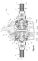
- FIG. 4a more specifically illustrates an axle system 150 including a differential unit 10 and one drive shaft 11 on both sides of the differential unit 10.
- the differential unit 10 comprises a differential carrier housing 20, which can made of a first housing portion 20a and a second housing portion 20b (also shown in figure 8d ) secured to one another by means of appropriate fasteners (not shown).
- the differential carrier housing 20 can made of a single piece.
- the differential unit can comprise a differential 15 - i.e. a mechanical differential.
- a crown wheel 22 having a longitudinal axis 23.
- the crown wheel 22 is driven in rotation around said longitudinal axis 23 by the input shaft 3, by engagement of teeth arranged on a pinion 21 mounted on said input shaft 3 and teeth arranged on the crown wheel 22.
- the differential 15 which comprises differential side pinions 16, for example four differential side pinions, which are fitted on a joint cross 17 attached to the crown wheel 22, and two differential side gears 18.
- Each differential side gear 18 meshes with at least one differential side pinion 16 and is fastened to the first end 111 of one of the drive shafts 11, i.e. to the first end 111 of the portion 114a of the drive shaft 111.
- the axis 115 of said portion 114a and the axis 23 of the crown wheel 22 are coincident.
- the differential unit 10 further comprises, inside the differential carrier housing 20, a differential housing arrangement 24 which contains the differential 15 and part of the drive shafts 11, more specifically part of the portion 114a of each drive shaft 11.
- the differential housing arrangement 24 is secured to the crown wheel 22. It may be made of two parts, namely two differential housings 24a, 24b each forming a sleeve around the corresponding differential side gears 18 and partly around the drive shaft 11. Said differential housings 24a, 24b may be fastened on both sides of the joint cross 17; other implementations may however be envisaged.
- the differential side gear 18 is mounted at the first end 111 of the drive shaft 11 in a rotationally fixed manner, for example by means of the splines 113. Furthermore, both the differential side gear 18 and the drive shaft 11 are rotatably mounted relative to the differential housing 24a, 24b around the longitudinal axis 23.
- the crown wheel 22, differential 15, and differential housing 24 are rotating parts inside and with respect to the differential carrier housing 20.
- differential housing 24 is also referred to as “first housing 24"
- differential carrier housing 20 is also referred to as “second housing 20”.
- the differential unit 10 may further comprise a blocking system 25 for blocking the differential unit operation, when required.
- the first housing 24 and joint cross 17 could be made to rotate not by a crown wheel driven by the engine 2, but by an motor (electric motor, hydraulic motor, etc.).
- the motor output shaft may be mechanically connected to the first housing 24 and joint cross 17 by means of a transmission system preferably including a gear system.
- the axle system 150 comprises a first bearing 30 which is secured around the drive shaft 11, and placed between the drive shaft 11 and the first housing 24.
- the drive shaft 11 is thus rotationally received in the first housing 24.
- the first bearing 30 includes an inner ring 31 and an outer ring 32, as well as rolling elements 33 which may be balls.
- the first bearing inner ring 31 is rotationally fastened to the drive shaft 11 and further axially fastened to the drive shaft 11. To that end, the first bearing inner ring 31 may be pushed against a shoulder 19 of the drive shaft 11 - forming a radial abutment - by means of an appropriate element such as nut 29. The first bearing inner ring 31 may be in contact with the shoulder 19 (see for example figure 12d ), or an intermediate piece may be provided between the inner ring 31 and the shoulder 19 (see for example figure 4b ).
- the axle system 150 also comprises a second bearing 40 which is placed between the first housing 24 and the second housing 20.
- the second bearing 40 includes an inner ring 41 and an outer ring 42, as well as rolling elements 43 which may be tapered rollers.
- the outer diameter D30 of the first bearing 30 is smaller than the inner diameter D41 of the second bearing 40.
- the first bearing 30 and the second bearing 40 may have median planes P30, P40, respectively, which are orthogonal to the axis 23 and which are substantially coincident.
- the first bearing 30 and the second bearing 40 can be arranged coaxially the one inside the other. This significantly improves compactness, specifically in the longitudinal direction X (i.e. the transverse direction Y' of the vehicle 1).
- the outer diameter D30 of the first bearing 30 is smaller than the radial dimension D of the joint 110. Having a small bearing is advantageous, especially in terms of compactness, but the consequence is that access to the first bearing 30 is complicated, or even impossible, when the drive shaft 11 is mounted in the first housing 24. As the first bearing 30 is generally secured around the drive shaft 11 before the drive shaft 11 is inserted inside the first housing 24, then the first bearing 30 is necessarily hidden, or hard to access, when it is located in the first housing 24. However, the first bearing 30 has to be maintained axially, without mechanical play, for an efficient and robust implementation of the axle system 150.
- axle system 150 comprises at least one tightening member 50 configured to axially lock the first bearing outer ring 32 relative to the first housing 24. Furthermore, said tightening member 50 comprises at least one manoeuvring portion 51 which is arranged in an offset relation relative to the joint 110, when looking axially towards the differential unit 10. As a consequence, the tightening member manoeuvring portion 51 is visible and accessible despite the joint 110, at least during a tightening phase of the mounting process of the axle system 150.
- the tightening member 50 can be configured to axially tighten the first bearing outer ring 32 against a radial wall 26 of the first housing 24.
- the first housing 24 can form substantially a sleeve around axis 23, provided with an inwardly projecting rib forming said radial wall 26.
- the tightening member 50 comprises a nut.
- the tightening member 50 has an axis 53. It comprises a tightening portion 52, which may be formed as a sleeve coaxial with the drive shaft 11 in use and which is configured for abutting against the outer ring 32 of the first bearing 30.
- the tightening portion 52 may have an outer thread (not shown) for cooperating with an inner thread of the first housing 24.
- the tightening member 50 also comprises an outer annular flange 54.
- the flange 54 comprises at least one notch 51 which opens outwardly and which forms one manoeuvring portion.
- the flange 54 comprises several notches 51 regularly circumferentially spaced, forming a crenulated peripheral area A. Alternatively, the notch or notches 51 could open axially.
- the peripheral area A including the notches 51 has at least an outer diameter D51 that is larger than the radial dimension D of the joint 110, and preferably also an inner diameter that is larger than the radial dimension D of the joint 110.
- the notches 51 - i.e. the manoeuvring portions of the tightening member 50 - are located in an area A of the tightening member 50 which is radially outwardly offset from the joint 110, when looking axially towards the differential unit 10, or at least partially radially outwardly offset.
- the notches 51 can therefore receive a tool capable of moving the tightening member 50 axially relative to the first housing 24.
- the axle system may comprise a contact piece 60 secured around the drive shaft 11. Said contact piece 60 forms an intermediate piece between the inner ring 31 and the shoulder 19 as previously described.
- the contact piece 60 has a blocking portion 61 which may be formed as a sleeve coaxial with the drive shaft 11, and which is configured for abutting against the inner ring 31 of the first bearing 30.
- the first bearing inner ring 31 is therefore tightened between the contact piece blocking portion 61 and the nut 29.
- the contact piece 60 also has a contact portion 62 such as a cylindrical contact portion coaxial with the drive shaft 11.
- the contact portion 62 is arranged not to hide, or not to fully hide, the manoeuvring portion(s) 51, when looking axially towards the differential unit 10, in order to allow access to said manoeuvring portion(s) 51, for tightening the first bearing outer ring 32 against the first housing 24.
- the contact portion 62 preferably has an outer diameter D62 that is less than the outer diameter D51 of the tightening member peripheral area A.
- the contact portion 62 can be fully radially inwardly offset relative to the tightening member manoeuvring portion 51, or only partially offset, i.e. partly facing the peripheral area A along the longitudinal direction X, as shown in figure 4b .
- the axle system 150 also comprises an annular cover 70 having a central opening 71 for receiving the drive shaft 11.
- the annular cover 70 is removably fastened to the second housing 20 by means of appropriate fasteners 73 (see figures 4a and 8e ).
- annular seal 72 is mounted in the central opening 71 of the annular cover 70 and is in contact with the contact portion 62 of the contact piece 60.
- the annular seal 72 is arranged between the contact piece 60 - secured to the drive shaft 11 - and the annular cover 70 - secured to the second housing 20.
- the annular seal 72 can have an inner diameter (i.e. where the contact with the opposite piece occurs) that is larger than the radial dimension D of the joint 110 (in other words, D62 > D). This makes it possible to change the annular seal 72 when needed, for maintenance operations during the service life of the axle system 150, without requiring the drive shaft 11 to be removed from the differential unit 10. This also avoids damaging the annular seal 72 when the drive shaft 11 is mounted.
- the differential unit 10 is prepared, with the differential 15, the first housing 24, the second bearings 40 (on either side of the joint cross 17), and possibly the blocking system 25. Then, as shown in figure 8b , the assembly of figure 8a is inserted in the second housing 20. Differential nuts 44 are tightened to set the bevel set backlash and the preload of the second bearings 40.
- Two drive shaft sub-assemblies 160 are also prepared.
- one drive shaft sub-assembly 160 comprises a drive shaft 11 including at least one joint 110 between the first portion 114a configured to be connected to the differential unit 10 and an intermediate portion 114d.
- the drive shaft sub-assembly 160 also includes:
- annular seal 72 is mounted in the central opening 71 of the annular cover 70, for both covers 70. This step is not illustrated.
- the drive shaft sub-assembly 160 is then engaged in the assembly illustrated in figure 8b , in the first housing 24, in order to connect the drive shaft 11 to the differential unit 10, i.e. to insert the end of the drive shaft first portion 114a into the corresponding differential side gear 18 and to rotationally link the first portion 114a and the differential side gear 18.
- the first bearing 30 is thus placed between the drive shaft 11 and the first housing 24, as illustrated in figure 4a .
- the axle system 150 is as illustrated in figures 6 and 8d . It can be seen that the first bearing 30 is not visible, because of its small diameter D30. On the contrary, the tightening member 50 is not fully hidden, as its manoeuvring portion(s) 51 are radially located outward from the contact piece 60 and the joint 110, and inward from the differential nut 44. The manoeuvring portion(s) 51 being visible and accessible by an operator, the tightening member 50 can thus be operated, during a tightening phase of the axle system mounting process. In practice, a tool can be introduced in the notches 51 in order to rigidly secure (i.e. without play) the first bearing outer ring 32 relative to the first housing 24.
- the tightening member 50 is thus a partly external piece - at least during the tightening phase - which makes it possible to ensure tightening while the drive shaft 11 has already been mounted.
- the annular cover 70 equipped with the annular seal 72 can be mounted, by being engaged around the drive shaft 11 (on both sides of the second housing 20). In the mounted position, illustrated in figures 8e , 7 4a and 4b , the annular seal 72 is in contact with the outer face of the contact piece contact portion 62, and the annular cover 70 is fastened to the second housing 20 by the fasteners 73.
- the annular cover 70 is represented as a transparent piece, only its edge being illustrated with a dotted line. It can thus be seen that the tightening member manoeuvring portions 51 are not visible any more, as they are hidden by the annular seal 72, when looking axially towards the differential unit 10.
- the annular cover 70 may comprise at least one pin (not shown) protruding axially towards the differential 15 and configured to engage the differential nut 44, preferably the inner part thereof, to prevent rotation i.e. untightening of said differential nut 44.
- FIG. 9 A variant of the first embodiment is illustrated in figure 9 .
- the differential effect is achieved by the fact that the wheels are driven independently by a dedicated motor and corresponding transmission system, in a so-called torque vectoring technology.
- the motor is electric, however, other kinds of motors could be envisaged, such as a hydraulic motor.
- the driven wheel system 6 comprises one powertrain module 170 for rotating one drive shaft 11 and another powertrain module 170 for rotating the other drive shaft 11.
- One powertrain module 170 comprises a casing 171 and a powertrain system which is configured to drive the drive shaft 11, and which comprises:
- the transmission system may comprise a first epicyclic gear train 100 having a first axis A100, and a second epicyclic gear train 200 having a second axis A200 which is parallel to the first axis A100.
- the axes A100 and A200 are parallel to direction Y'.
- the first epicyclic gear train 100 may be omitted and replaced by a more conventional parallel gear train reduction arrangement.
- the first epicyclic gear train 100 can comprise:
- the second epicyclic gear train 200 can comprise:
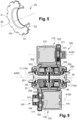
- a first bearing 30 is mounted between the drive shaft 11 and the casing 171, while a second bearing 40 is mounted between the casing 171 and the hub 205.
- the axle system 150 may be devoid of a contact piece 60 as previously described. Rather, the drive shaft 11 - more specifically the first portion 114a - may comprise a stepped portion including a transverse face or shoulder 19 which forms an axial abutment for the first bearing 30 and a cylindrical face which forms a contact portion 63 with which the annular seal 72 is in contact in use.
- the diameter of the cylindrical face 63 can be less than the radial dimension D of the joint 110, which means that the annular seal 72 has an inner diameter that is smaller than the radial dimension D of the joint 110. Besides, the diameter of the cylindrical face 63 is preferably larger than the first bearing inner diameter.
- Two drive shaft sub-assemblies 160 are prepared as shown in figure 10 .
- One drive shaft sub-assembly 160 comprises a drive shaft 11 including at least one joint 110 between the first portion 114a configured to be connected to the differential unit 10 and an intermediate portion 114d.
- the drive shaft sub-assembly 160 also includes:
- a bearing rotation lock 35 can further be provided on the side of the first bearing 30 that is opposite the annular cover 70, i.e. towards the inside of the differential unit 10.
- the annular cover 70 comprises at least one aperture 74 (see figure 11 ), preferably several apertures 74 arranged substantially on one and the same circle around axis 115.
- the apertures 74 are located in an area A74 which is at least partially included in the joint enveloping cylinder C.
- the annular cover 70 is placed or can be placed around the drive shaft 11 so that the apertures 74 are in a circumferentially offset position from the joint 110, i.e. in a circumferentially offset position from both U-shaped pieces 116, 117.
- the differential unit 10 is also prepared, with the differential 15, the first housing 24, the second bearings 40 (on either side of the joint cross 17), and possibly the blocking system 25.
- the drive shaft sub-assembly 160 of figure 11 is inserted in the differential unit 10.
- the drive shaft sub-assembly 160 is then engaged in the assembly illustrated in figure 8b , in the first housing 24, in order to connect the drive shaft 11 to the differential unit 10, i.e. to insert the end of the drive shaft first portion 114a into the corresponding differential side gear 18 and to rotationally link the first portion 114a and the differential side gear 18.
- the first bearing 30 is thus placed between the drive shaft 11 and the first housing 24.
- the engagement of the drive shaft 11 can continue until the first bearing 30 abuts against the first housing 24, as illustrated in figure 12b .
- the tightening phase of the first bearing outer ring 32 can be carried out, in order to axially lock the first bearing outer ring 32 relative to the first housing 24.
- at least one tightening member 50 as a separate piece.
- One tightening member 50 may comprise a plate configured for abutting against the outer ring 32 of the first bearing 30.
- the plate can be substantially flat. It is designed to be inserted through one aperture 74 of the annular cover 70, and therefore is dimensioned appropriately.
- Each plate 50 comprises at least one hole, and preferably at least two holes, which form a manoeuvring portion 51 of the tightening member 50, as a tool can be engaged in the hole 51 to move the plate 50 axially relative to the first housing 24.
- the tightening members 50 are arranged substantially on one and the same circle. Moreover, when looking axially towards the differential unit 10, the manoeuvring portions 51 are located in an area A74 at least partially included in the joint enveloping cylinder C but are circumferentially offset from the U-shaped pieces 116, 117 of the joint 110.
- one tightening member i.e. one plate 50
- one tightening member is inserted through several or each aperture 74, until it abuts against the outer ring 32 of the first bearing 30, as shown in figure 12b .
- the aperture 74 axially facing the tightening member 50, it allows access to the holes 51, i.e. the manoeuvring portions.
- the bearing 30 can thus be properly axially locked.
- the annular cover 70 can then be removably plugged or fastened to the second housing 20, by means of the fasteners 73.
- the annular seal 72 is thus arranged between the drive shaft 11 and the annular cover 70 secured to the second housing 20.
- the invention applies to vehicles having an independent wheel suspension arrangement in which, for mechanical strength reasons, for providing enough space to allow operational movements of the components, and for improving fuel efficiency, the drive shafts must have a minimum length that may not be easily compatible with the legal constraints, namely the regulatory maximum transverse length of the vehicle.
- the invention gives a solution for providing an axle system which offers both stronger support for the drive shafts, because of the first and second bearings, and robustness, as axial blocking is achieved without play which avoid relative movements and resulting components wear.
- the mutual arrangement of the bearings offers the required compactness, especially in the transverse direction of the vehicle.
- the invention allows easing maintenance on the drive shafts, which can be disassembled without disassembling the differential (as disassembling the drive shafts occurs at an early stage of the disassembling process), and also easing maintenance on the seal, as it can be quickly changed, at least in the first embodiment.
- the invention advantages are all the more significant as independent wheel suspension configuration is a key solution to develop an optimized electrified driveline, which is a promising development in transportation industry.
Landscapes
- Engineering & Computer Science (AREA)
- General Engineering & Computer Science (AREA)
- Mechanical Engineering (AREA)
- Chemical & Material Sciences (AREA)
- Combustion & Propulsion (AREA)
- Transportation (AREA)
- Retarders (AREA)
Description
- The invention relates to an axle system for a vehicle. The invention also relates to a drive shaft sub assembly for such an axle system, to a driven wheel system comprising such an axle system and to a vehicle comprising at least one such driven wheel system. The invention further relates to a process for mounting such an axle system.
- A vehicle such as a truck is generally equipped with one or several differential units on its driven axles, to allow the left and right wheels of said axle to have different speeds when turning/manoeuvring.
-
- As the transverse width of a vehicle, in particular a truck, is limited to a maximum value given by regulatory requirements, other vehicle components need to be fairly compact, which in particular applies to the powertrain system, especially the differential unit.
- Such a space constraint is even more significant in some vehicle configurations:
- for electric vehicles, as they require significant space for batteries;
- for vehicles not comprising a mechanical differential, but implementing a torque vectoring solution. This creates packaging issues since the left and right wheels need to be independently driven, duplicating the transmission from the motor(s) to the wheel(s);
- for vehicles having an independent wheel suspension configuration, to which the invention more particularly applies.
- A trend in transport industry, in particular in heavy duty transport industry, is to move from rigid axles to independent wheel suspension configurations, to improve several features (dynamic behavior, volume capacity for battery / fuel, wheel alignment, comfort, etc.). To get maximized battery / fuel efficiency from an independent wheel suspension driveline, wheel reduction (hub reduction) should be avoided. Without such a wheel reduction, the drive shafts have to be bigger. Moreover, these drive shafts must have a minimum length to support driveline torque and keep acceptable working angles, in order not to compromise the suspension stroke and consequently the comfort.
- The width of vehicle being legally constrained, and a minimum length being needed for the drive shaft for torque and angle constraints, there is a need for an as much as possible compact differential unit in the vehicle transverse direction.
- Other constraints derive from the independent wheel suspension configuration, such as the need for a stronger support of the drive shafts both in the differential unit area and in the wheel area, or the need to secure each drive shaft in translation, in both directions along the vehicle transverse direction and without play, in the differential unit, to avoid a greatly limit wear.
- All these requirements have to be taken into account, bearing in mind that the mounting process of the whole vehicle driven wheel system must preferably not be significantly complicated nor take much longer. The same applies to maintenance operations.
- An object of the invention is to provide an improved axle system for a vehicle which solves at least one of the problems of the prior art.
- In particular, the invention aims at improving compactness, and at making the mounting process and/or the maintenance operations easier.
- To that end, and according to a first aspect, the invention concerns an axle system for a vehicle, as set forth in
claim 1. - Providing an axle system including a first bearing, in addition to the second bearing, makes it possible to better support and guide the drive shaft in rotation inside the differential. Owing to the invention, this advantage is not obtained to the detriment of compactness, as explained below.
- Indeed, by providing a first bearing having a smaller outer diameter than the radial dimension of the joint, the invention greatly improves the compactness. As a result, the differential unit is more compact in the radial direction but also as a whole. Indeed, a small first bearing can more easily be housed in a limited space and, in some embodiments, can be appropriately and efficiently arranged relative to the surrounding components to further limit compactness, including in other directions than the radial direction. Besides, as the first bearing has a fairly small outer diameter, it does not require other components of the differential unit to be sized as large and/or resistant parts. Therefore, the overall size, weight and cost of the differential unit are reduced.
- However, with such a configuration, due to its small outer diameter, the fist bearing can be hidden by the joint or another component of the axle system, when looking axially towards the differential unit. As a consequence, the first bearing cannot be accessed nor easily axially blocked by conventional tightening means.
- This is the reason why the invention further provides a specific tightening member having a specifically designed manoeuvring portion for allowing a user to easily and efficiently tighten said tightening member. In concrete terms, the terms "arranged in an offset relation relative to the joint" mean that the manoeuvring portion and the joint are not superimposed, or at least partially not superimposed, when looking axially towards the differential unit.
- The tightening member is used to axially lock the first bearing outer ring relative to the first housing, i.e. to axially maintain the first bearing outer ring relative to the first housing, in both directions, without play. This prevents or greatly limits wear on the components due to high axial forces, in both directions and at high frequency.
- The invention thus makes it possible to improve compactness without negative effects on the assembly and structure quality of the axle system nor on the ease of the mounting process.
- "Axle system" has to be understood as the set of pieces that joins two wheels, and is not limited to a rigid axle. In the present invention, the axle system is not rigid as the drive shafts include joints. In practice, the axle system comprises two drive shafts, one on each side of the differential unit. The joint can be a universal joint, a homocinetic joint, a Rzeppa joint, or any other kind of joint capable of coupling connecting rigid rods whose axes are inclined to each other and to transmit rotary motion between said rigid rods.
- "Differential unit" refers to a unit providing a differential effect, in order to allow the outer drive wheel to rotate faster than the inner drive wheel during a turn. Such a differential unit can include a mechanical differential. Alternatively, the differential effect can be achieved by the fact that the wheels are driven independently by a dedicated motor, preferably but not exclusively an electric motor, and corresponding transmission system, in a so-called torque vectoring technology.
- In concrete terms, the radial dimension of the joint is the diameter of the smallest cylinder which has its centre on the axis, and which fully contains the joint, when the drive shaft is in a straight configuration (also called "enveloping cylinder"). The joint is not necessarily a rotationally symmetric piece; it can have at least a first radial dimension along one direction, and a second radial dimension different from the first radial dimension along another direction. The largest dimension among the first and the second radial dimensions is then the joint radial dimension.
- In practice, the second housing can be an outer part that does not rotate relative to the vehicle chassis, while the first housing can be an inner rotating part relative to the vehicle chassis.
- According to an embodiment, the first bearing outer diameter can be smaller than the second bearing inner diameter. Such a configuration allows reducing the space required in the radial direction.
- In addition, advantageously, the first bearing and the second bearing may have median planes which are orthogonal to the axis and which are substantially coincident. In other words, with this configuration, the first bearing is arranged inside the second bearing. This further reduces the space required in the transverse direction. The term "coincident" includes a configuration in which the median planes are offset by less than 50 % of the axial length of the first bearing, preferably less than 30 %, more preferably less than 20 %.
- The first housing may comprise a radial wall, the tightening member being configured to axially tighten the first bearing outer ring against said radial wall. Said radial wall may be a piece distinct from the first housing but secured to the first housing. Said radial wall - which extends in a plane orthogonal to the axis - thus forms an axial abutment.
- The tightening member manoeuvring portion can comprise at least one hole, recess or the like, configured to receive a tool capable of moving the tightening member axially relative to the first housing.
- The tightening member can comprise several manoeuvring portions which are all arranged in an offset relation relative to the joint, and which are preferably arranged substantially on one and the same circle.
- The axle system can comprise several tightening members, each tightening member comprising at least one manoeuvring portion which is arranged in an offset relation relative to the joint, the tightening members preferably being arranged substantially on one and the same circle.
- The term "circle" is not limited to a line but includes an annular zone having a small radial dimension.
- The axle system may further comprise a seal arranged between the drive shaft - or a part secured to the drive shaft - and the second housing - or a part secured to the second housing, the seal preferably having an annular shape.
- The axle system may further comprise a cover having an opening for receiving the drive shaft, the cover being configured to be removably mounted on and/or fastened to the second housing after the tightening phase of the axle system mounting process. In an embodiment, the cover may cover the manoeuvring portion. However, other implementations may be envisaged. The cover can have an annular shape, the opening being then centrally arranged in the cover.
- The seal may be mounted in the cover opening. In an embodiment, the annular seal is mounted in the central opening of the annular cover.
- In an implementation, the axle system comprises a left drive shaft connected to the differential unit and configured to be connected to at least one left wheel, and a right drive shaft connected to the differential unit and configured to be connected to at least one right wheel, the differential unit further comprising a differential which mechanically links the two drive shafts. At least one of the drive shafts is made to rotate:
- by a crown wheel of the axle system which is connected to the differential and configured to be connected to an input shaft driven by a vehicle engine or by a vehicle electric motor;
- or by at least one motor (electric motor, hydraulic motor, etc.), through a transmission system.
- The differential may further comprise a blocking system for blocking the differential operation.
- In another implementation, the differential effect is not achieved by means of a differential but through torque vectoring technology. Then, the axle system comprises a left drive shaft connected to the differential unit and configured to be connected to at least one left wheel, and a right drive shaft connected to the differential unit and configured to be connected to at least one right wheel. The differential unit further comprises at least one motor (electric motor, hydraulic motor, etc.) capable of rotating the left drive shaft through a transmission system, and at least one motor (electric motor, hydraulic motor, etc.) capable of rotating the right drive shaft through a transmission system, independently from the left drive shaft.
- According to a first embodiment of the invention, the manoeuvring portion of the tightening member is located in an area of the tightening member which is radially outside from the joint enveloping cylinder - i.e. the smallest cylinder which has its centre on the axis, and which fully contains the joint - when looking axially towards the differential unit. In other words, said area of the tightening member is radially outwardly offset from the joint. For example, said manoeuvring portion can be located in an annular area having a diameter that is larger than the radial dimension of the joint.
- The manoeuvring portion of the tightening member can be located in a peripheral area of the tightening member.
- For example, the tightening member can comprise a nut having:
- a tightening portion, such as a sleeve coaxial with the drive shaft, configured for abutting against the outer ring of the first bearing;
- and an outer annular flange comprising at least one notch which opens outwardly and which forms the manoeuvring portion.
- The annular seal may have an inner diameter that is larger than the radial dimension of the joint. This disposition is advantageous in that the annular seal may be replaced when needed without disassembling the drive shaft. The maintenance is thus significantly improved.
- The axle system may comprise a contact piece secured around the drive shaft and having:
- a blocking portion, such as a sleeve coaxial with the drive shaft, configured for abutting against the inner ring of the first bearing;
- a contact portion, such as a cylindrical contact portion coaxial with the drive shaft, with which the annular seal is radially in contact, wherein, preferably, the contact portion is radially inwardly offset relative to the tightening member manoeuvring portion.
- By providing a contact portion which is radially inwardly offset relative to the tightening member manoeuvring portion, the invention ensures that access to the manoeuvring portion is not impeded by the contact piece. In other words, the contact piece can be mounted before the tightening phase. For example, there may be provided several manoeuvring portions arranged substantially on one and the same circle (or annular area) having a larger diameter than the contact portion.
- In use, the contact portion of the contact piece can turn inside and against the annular seal; the annular seal and the annular cover can hide the tightening member manoeuvring portion.
- According to a second embodiment of the invention, when looking axially towards the differential unit, the manoeuvring portion of the tightening member is located in an area at least partially included in the joint enveloping cylinder - i.e. the smallest cylinder which has its centre on the axis, and which fully contains the joint -and the manoeuvring portion of the tightening member is circumferentially offset from the joint or each portion of the joint. As the manoeuvring portion is located in an area at least partially included in the joint enveloping cylinder, it would not be accessible for being tightened if not circumferentially offset from the joint or each portion of the joint.
- The tightening member can comprise at least one plate configured for abutting against the outer ring of the first bearing, the plate being preferably substantially flat, and preferably having a transverse dimension less than the inner diameter of the first bearing. The "transverse dimension" means the dimension in a transverse plane, i.e. a plane orthogonal to the axis. In concrete terms, the plate can be disc-shaped, its transverse dimension then being its diameter.
- In other words, the plate is preferably a localized and separate piece. For example, the plate can be disc shaped. It can comprise at least one hole - for example two holes - for receiving a screw or another fastener. There may preferably be provided several distinct plates (for example four plates) regularly arranged around the axis.
- The annular cover can comprise at least one aperture substantially axially facing the tightening member, so as to allow access to the manoeuvring portion. For example, the plate can have the same shape and dimensions that the aperture, so that it can be engaged through the aperture.
- The annular seal may have an inner diameter that is smaller than the radial dimension of the joint. With such a configuration, the annular seal cannot be removed after the mounting process has been completed. However, a smaller seal is more energy efficient and accepts higher rotational speeds.
- The drive shaft can comprise a stepped portion including a transverse face which forms an axial abutment for the first bearing, and a cylindrical face which forms a contact portion with which the annular seal is in contact, the diameter of the cylindrical face being equal or larger than the first bearing inner diameter. Preferably, the outer diameter of the annular seal is smaller than the first bearing outer diameter. The first bearing is thus hidden by the joint, the annular seal and the annular cover.
- In use, the contact portion of the drive shaft stepped portion turns inside and against the annular seal.
- According to a second aspect, it is described a drive shaft sub assembly for an axle system as previously described, the drive shaft sub assembly comprising a drive shaft, wherein the drive shaft has one end configured to be connected to a vehicle wheel and one end connected to a differential unit of the axle system, the drive shaft including at least one joint connecting two portions of the drive shaft to transmit rotary motion between said portions, the joint having a radial dimension.
- The drive shaft sub assembly may comprise:
- a first bearing having an inner ring secured around the drive shaft, the outer diameter of the first bearing being smaller than the radial dimension of the joint;
- a tightening member, such as a nut, having a tightening portion which is configured for abutting against the outer ring of the first bearing and a manoeuvring portion which is radially outwardly offset from the joint, when looking axially towards the differential unit;
- and a contact piece secured around the drive shaft, having a blocking portion which is configured for abutting against the inner ring of the first bearing, and a contact portion for an annular seal, said contact portion being cylindrical, radially inwardly offset relative to the tightening member manoeuvring portion, and preferably having a diameter larger than the radial dimension of the joint.
- Both the tightening member and the contact piece can be located between the first bearing and the joint; a nut can be provided on the side of the ring that is opposite the contact piece, in the axial direction.
- Alternatively, the drive shaft sub assembly may comprise:
- a first bearing having an inner ring secured around the drive shaft, the outer diameter of the first bearing being smaller than the radial dimension of the joint;
- an annular cover having a central opening in which the drive shaft is received, an annular seal being mounted between the drive shaft and said central opening, the annular cover being located between the first bearing and the joint and comprising at least one aperture which, when looking axially towards the differential unit, is located in an area at least partially included in the joint enveloping cylinder - i.e. the smallest cylinder which has its centre on the axis, and which fully contains the joint - and can be placed in a circumferentially offset position from the joint or each portion of the joint, the aperture being configured to allow a tightening member to be inserted through it until it abuts against the outer ring of the first bearing.
- According to a third aspect, the invention concerns a driven wheel system for a vehicle, comprising an axle system as previously described, at least one left wheel and at least one right wheel, the axle system comprising a left drive shaft connected to the differential unit and to the left wheel(s), and a right drive shaft connected to the differential unit and to the right wheel(s), each wheel being further connected to the differential unit by at least one lower arm articulated at both ends and preferably at least one upper arm articulated at both ends.
- According to a fourth aspect, the invention concerns a vehicle comprising at least one driven wheel system as previously described.
- According to a fifth aspect, the invention relates to a process for mounting an axle system as previously described, the process comprising the following steps:
- a) providing a differential unit with a second bearing placed between the first housing and the second housing;
- b) providing a drive shaft sub-assembly comprising a drive shaft including at least one joint connecting two portions of the drive shaft to transmit rotary motion between said portions, the joint having a radial dimension, the drive shaft sub-assembly further comprising a first bearing having an inner ring secured around the drive shaft, the outer diameter of the first bearing being smaller than the radial dimension of the joint;
- c) providing a tightening member;
- d) after steps a), b) and c), engaging the drive shaft sub-assembly in the first housing so that the first bearing is placed between the drive shaft and the first housing, and connecting the drive shaft to the differential unit;
- e) after step d), tightening the tightening member in order to axially lock the first bearing outer ring relative to the first housing in the mounted position.
- Owing to the invention, the drive shaft can be mounted at a late step of the mounting process, which makes said process significantly easier. Indeed, the number of subsequent mounting steps to be performed with the drive shaft already assembled, i.e. to be performed with a heavy and cumbersome system, are limited. The invention thus meets the strong demand to have the drive shaft kept as pre-assembled units (as these drive shafts need to be dynamically equilibrated) without significant negative impact on the mounting process.
- According to an embodiment, in step c), the tightening member is provided as a piece mounted on the drive shaft, before the drive shaft sub-assembly is engaged in the first housing.
- According to another embodiment, in step c), the tightening member is provided as a separate piece, and in that the tightening member is assembled to the axle system once the drive shaft sub-assembly has been engaged in the first housing. By "separate piece" is meant that the tightening member is not fastened to another piece (of the differential unit or of the drive shaft sub-assembly).
- Further advantages and advantageous features of the invention are disclosed in the following description and in the dependent claims.
- With reference to the appended drawings, below follows a more detailed description of embodiments of the invention cited as examples.
- In the drawings:
-
Fig. 1 is a schematic drawing of an underside of a vehicle showing a driven wheel system including a differential unit according to an embodiment of the invention; -
Fig. 2 is a schematic view of an embodiment of a driven wheel system; -
Fig. 3 is a perspective view of one drive shaft pertaining to the driven wheel system ofFig. 2 ; -
Fig. 4a is a partial and cross section view of an axle system according to a first embodiment of the invention, including a tightening member, an annular seal and an annular cover, as well as a mechanical differential; -
Fig. 4b is a detailed enlarged view ofFig. 4a ; -
Fig. 5 is a perspective, partially cut out, view of a tightening member of the axle system ofFig. 4a ; -
Fig. 6 is a side view of the axle system ofFig. 4a without seal nor cover; -
Fig. 7 is a side view of the axle system ofFig. 4a with the annular seal and the annular cover, the annular cover being transparent and represented by a dotted line; -
Fig. 8a to 8e show various successive steps of the mounting process of the axle system ofFig. 4a ; -
Fig. 9 is a partial and cross section view of an axle system according to a variant of the first embodiment, including at least one motor to drive each one of the two drive shafts, to achieve a differential effect through torque vectoring technology; -
Fig. 10 is a cross section view of a drive shaft sub assembly according to a second embodiment of the invention; -
Fig. 11 is a perspective view of the drive shaft sub assembly ofFig. 10 ; -
Fig. 12a to 12d show various successive steps of the mounting process of an axle system comprising the drive shaft sub assembly ofFig. 10 . - The invention can be applied in heavy-duty vehicles, such as trucks, buses and construction equipment, as well as medium-duty vehicles.
- As shown in
Figure 1 , avehicle 1 comprises at least one drivenwheel system 6. In the illustrated embodiment, thevehicle 1 comprises a first driven rear wheel system 6a and a second driven rear wheel system 6b located rearwards from the first driven rear wheel system 6a. Thevehicle 1 further includes afront axle 4 connected tofront wheels 5. - Although the invention is described for a rear driven wheel system, it can be used in another driven wheel system, especially in a front driven wheel system.
- The or each driven
wheel system 6 has anaxis 12, and comprises adifferential unit 10, i.e. a unit providing a differential effect, in order to allow the outer drive wheel to rotate faster than the inner drive wheel during a turn. - The driven
wheel system 6 further comprises twodrive shafts 11, namely a left drive shaft connected to thedifferential unit 10 and to at least oneleft wheel 8, and a right drive shaft connected to thedifferential unit 10 and to at least oneright wheel 8. Each rear wheel system 6a, 6b can comprise twowheels 8 on either side, thus forming a dual mounted tires arrangement. However, this should not be considered as limitative. - In the embodiment illustrated in
figure 1 , thevehicle 1 comprises anengine 2 that drives aninput shaft 3 having anaxis 13. Thedifferential unit 10 includes a differential 15 which is driven by theinput shaft 3 and which transmits the appropriate torque to the left andright drive shafts 11. Anadditional shaft 9 connects theinput shaft 3 to thedifferential unit 10 of the second driven rear wheel system 6b, through thedifferential unit 10 of the first driven rear wheel system 6a, and is the input shaft for thedifferential unit 10 of the second driven rear wheel system 6b. - Alternatively, as will be described with reference to
figure 9 , the invention can be applied to an electric vehicle. Such a vehicle does not include anengine 2 nor the corresponding driveline, but rather at least one electric motor. Either one motor (or more) is used to drive a correspondingdrive shaft 11, the drive shafts thus being independently driven by one or more dedicated motors, with the appropriate torque (seefigure 9 ); or one motor (or more) is used to drive a mechanical differential rotating thedrive shafts 11 with the appropriate torques (variant not illustrated). - The invention concerns a
vehicle 1 having an independent wheel configuration, as schematically illustrated infigure 2 . In such a configuration, the left wheel(s) 8 and the right wheel(s) 8 are each connected to thedifferential unit 10 by means of the correspondingdriveshaft 11, at least one joint 110 (such as a universal i.e. a cardan joint, or another kind of joint), at least onelower arm 14b articulated at both ends, and preferably at least oneupper arm 14a articulated at both ends. Although infigure 2 thedifferential unit 10 is shown as including a differential 15, other implementations are possible. - As shown in
figure 3 , thedrive shaft 11 comprises afirst end 111 configured to be connected to thedifferential unit 10 and asecond end 112 configured to be connected to awheel 8 of thevehicle 1. Thefirst end 111 and thesecond end 112 may be provided withsplines 113 or another system providing a rotationally blocked connection with thedifferential unit 10 / thewheel 8. - The
drive shaft 11 is made of several rigid portions 114. In the embodiment illustrated infigure 3 , there are provided afirst portion 114a configured to be connected to thedifferential unit 10, asecond portion 114b configured to be connected to awheel 8, and twointermediate portions axis 12 to form a telescopic intermediate piece, in order to adjust the drive shaft length to the suspension stroke. Thefirst portion 114a has anaxis 115. - As can be seen in
figures 1 to 3 , the longitudinal direction X is defined as a direction parallel to theaxis 12 of a drivenwheel system 6, which joins thewheels 8 when thedrive shaft 11 is in a straight configuration as illustrated infigure 3 . In the operating position, i.e. when the differential unit is mounted under thevehicle 1, as shown infigure 1 , the longitudinal direction X corresponds the transverse direction Y' of thevehicle 1. Direction X is substantially horizontal when thevehicle 1 is on a horizontal surface. - Besides, the transverse direction Y is defined as the direction which is orthogonal to the longitudinal direction X and substantially horizontal when the
vehicle 1 is on a horizontal surface. Direction Y corresponds the longitudinal direction X' of thevehicle 1. Theaxis 13 of theinput shaft 3 is roughly parallel to the transverse direction Y, i.e the longitudinal direction X' of thevehicle 1, or inclined relative to the transverse direction Y, horizontally and/or vertically, by preferably less than 5°. - Moreover, direction Z is defined as the vertical direction - when the
vehicle 1 is on a horizontal surface. - The invention will be described when the
vehicle 1 is on a horizontal surface. -
Portion 114a andportion 114d, on the one hand, andportion 114b andportion 114c, on the other hand, are connected by a joint 110. In the embodiment illustrated in the figures, each joint 110 is a universal joint. However, this should not be considered as limitative; any other type of joint which is configured for transmitting rotary motion between said adjacent portions 114 could be implemented. - The joint 110 has a radial dimension D, which is defined as the largest dimension of the joint 110 in a plane (Y,Z). In other word, the radial dimension is the diameter of the smallest cylinder C (called "enveloping cylinder") which has its centre on the
axis 12, and which fully contains the joint 110, when the drive shaft has a straight configuration. - For example, with a universal joint as illustrated in
figure 3 , the joint 110 comprises twoU-shaped pieces U-shaped piece 116 has a radial length D1, i.e. the radial length between the ends of the U; the otherU-shaped piece 117 has a radial length D2 which is larger than D1. In this embodiment, the radial dimension D of the joint 110 is defined along a direction which is inclined relative to the directions along which D1 and D2 are defined; D is a bit higher than D2. - Reference is now made to
figures 4a to 9 which show a first embodiment of the invention.Figure 4a more specifically illustrates anaxle system 150 including adifferential unit 10 and onedrive shaft 11 on both sides of thedifferential unit 10. - One variant of this first embodiment is illustrated in
figures 4a to 8e . - The
differential unit 10 comprises adifferential carrier housing 20, which can made of afirst housing portion 20a and asecond housing portion 20b (also shown infigure 8d ) secured to one another by means of appropriate fasteners (not shown). In another implementation, thedifferential carrier housing 20 can made of a single piece. - The differential unit can comprise a differential 15 - i.e. a mechanical differential.
- Inside the
differential carrier housing 20 can be located acrown wheel 22 having alongitudinal axis 23. Thecrown wheel 22 is driven in rotation around saidlongitudinal axis 23 by theinput shaft 3, by engagement of teeth arranged on apinion 21 mounted on saidinput shaft 3 and teeth arranged on thecrown wheel 22. - Inside the
crown wheel 22 is arranged the differential 15 which comprises differential side pinions 16, for example four differential side pinions, which are fitted on ajoint cross 17 attached to thecrown wheel 22, and two differential side gears 18. Eachdifferential side gear 18 meshes with at least onedifferential side pinion 16 and is fastened to thefirst end 111 of one of thedrive shafts 11, i.e. to thefirst end 111 of theportion 114a of thedrive shaft 111. In the mounted position, theaxis 115 of saidportion 114a and theaxis 23 of thecrown wheel 22 are coincident. - The
differential unit 10 further comprises, inside thedifferential carrier housing 20, adifferential housing arrangement 24 which contains the differential 15 and part of thedrive shafts 11, more specifically part of theportion 114a of eachdrive shaft 11. Thedifferential housing arrangement 24 is secured to thecrown wheel 22. It may be made of two parts, namely two differential housings 24a, 24b each forming a sleeve around the corresponding differential side gears 18 and partly around thedrive shaft 11. Said differential housings 24a, 24b may be fastened on both sides of thejoint cross 17; other implementations may however be envisaged. - Thus, on each side of the
joint cross 17, thedifferential side gear 18 is mounted at thefirst end 111 of thedrive shaft 11 in a rotationally fixed manner, for example by means of thesplines 113. Furthermore, both thedifferential side gear 18 and thedrive shaft 11 are rotatably mounted relative to the differential housing 24a, 24b around thelongitudinal axis 23. Thecrown wheel 22, differential 15, anddifferential housing 24 are rotating parts inside and with respect to thedifferential carrier housing 20. - In this application, the
differential housing 24 is also referred to as "first housing 24", while thedifferential carrier housing 20 is also referred to as "second housing 20". - The
differential unit 10 may further comprise ablocking system 25 for blocking the differential unit operation, when required. - It has to be noted that, according to an alternative implementation of
figure 4a , not show, thefirst housing 24 andjoint cross 17 could be made to rotate not by a crown wheel driven by theengine 2, but by an motor (electric motor, hydraulic motor, etc.). In such a configuration of thevehicle 1, the motor output shaft may be mechanically connected to thefirst housing 24 andjoint cross 17 by means of a transmission system preferably including a gear system. - The way one
drive shaft 11, more precisely theportion 114a of thedrive shaft 11, is arranged in thedifferential unit 10 will now be described, bearing in mind that the left and right arrangements are structurally identical, while their respective dimensions may be different. - The
axle system 150 comprises afirst bearing 30 which is secured around thedrive shaft 11, and placed between thedrive shaft 11 and thefirst housing 24. Thedrive shaft 11 is thus rotationally received in thefirst housing 24. Thefirst bearing 30 includes aninner ring 31 and anouter ring 32, as well as rollingelements 33 which may be balls. - The first bearing
inner ring 31 is rotationally fastened to thedrive shaft 11 and further axially fastened to thedrive shaft 11. To that end, the first bearinginner ring 31 may be pushed against ashoulder 19 of the drive shaft 11 - forming a radial abutment - by means of an appropriate element such asnut 29. The first bearinginner ring 31 may be in contact with the shoulder 19 (see for examplefigure 12d ), or an intermediate piece may be provided between theinner ring 31 and the shoulder 19 (see for examplefigure 4b ). - The
axle system 150 also comprises asecond bearing 40 which is placed between thefirst housing 24 and thesecond housing 20. Thesecond bearing 40 includes aninner ring 41 and anouter ring 42, as well as rollingelements 43 which may be tapered rollers. - In a particularly compact non limitative embodiment, the outer diameter D30 of the
first bearing 30 is smaller than the inner diameter D41 of thesecond bearing 40. Furthermore, thefirst bearing 30 and thesecond bearing 40 may have median planes P30, P40, respectively, which are orthogonal to theaxis 23 and which are substantially coincident. Thus, thefirst bearing 30 and thesecond bearing 40 can be arranged coaxially the one inside the other. This significantly improves compactness, specifically in the longitudinal direction X (i.e. the transverse direction Y' of the vehicle 1). - According to the invention, the outer diameter D30 of the
first bearing 30 is smaller than the radial dimension D of the joint 110. Having a small bearing is advantageous, especially in terms of compactness, but the consequence is that access to thefirst bearing 30 is complicated, or even impossible, when thedrive shaft 11 is mounted in thefirst housing 24. As thefirst bearing 30 is generally secured around thedrive shaft 11 before thedrive shaft 11 is inserted inside thefirst housing 24, then thefirst bearing 30 is necessarily hidden, or hard to access, when it is located in thefirst housing 24. However, thefirst bearing 30 has to be maintained axially, without mechanical play, for an efficient and robust implementation of theaxle system 150. - To solve this problem, there
axle system 150 comprises at least one tighteningmember 50 configured to axially lock the first bearingouter ring 32 relative to thefirst housing 24. Furthermore, said tighteningmember 50 comprises at least one manoeuvringportion 51 which is arranged in an offset relation relative to the joint 110, when looking axially towards thedifferential unit 10. As a consequence, the tighteningmember manoeuvring portion 51 is visible and accessible despite the joint 110, at least during a tightening phase of the mounting process of theaxle system 150. - For example, the tightening
member 50 can be configured to axially tighten the first bearingouter ring 32 against aradial wall 26 of thefirst housing 24. In practice, thefirst housing 24 can form substantially a sleeve aroundaxis 23, provided with an inwardly projecting rib forming saidradial wall 26. - In the embodiment shown in
figure 4a , the tighteningmember 50 comprises a nut. As best seen infigure 5 , the tighteningmember 50 has anaxis 53. It comprises a tighteningportion 52, which may be formed as a sleeve coaxial with thedrive shaft 11 in use and which is configured for abutting against theouter ring 32 of thefirst bearing 30. The tighteningportion 52 may have an outer thread (not shown) for cooperating with an inner thread of thefirst housing 24. The tighteningmember 50 also comprises an outerannular flange 54. Theflange 54 comprises at least onenotch 51 which opens outwardly and which forms one manoeuvring portion. Preferably, theflange 54 comprisesseveral notches 51 regularly circumferentially spaced, forming a crenulated peripheral area A. Alternatively, the notch ornotches 51 could open axially. - As shown in
figure 4b , the peripheral area A including thenotches 51 has at least an outer diameter D51 that is larger than the radial dimension D of the joint 110, and preferably also an inner diameter that is larger than the radial dimension D of the joint 110. - Thus, the notches 51 - i.e. the manoeuvring portions of the tightening member 50 - are located in an area A of the tightening
member 50 which is radially outwardly offset from the joint 110, when looking axially towards thedifferential unit 10, or at least partially radially outwardly offset. Thenotches 51 can therefore receive a tool capable of moving the tighteningmember 50 axially relative to thefirst housing 24. - The axle system may comprise a
contact piece 60 secured around thedrive shaft 11. Saidcontact piece 60 forms an intermediate piece between theinner ring 31 and theshoulder 19 as previously described. - The
contact piece 60 has a blockingportion 61 which may be formed as a sleeve coaxial with thedrive shaft 11, and which is configured for abutting against theinner ring 31 of thefirst bearing 30. The first bearinginner ring 31 is therefore tightened between the contactpiece blocking portion 61 and thenut 29. - The
contact piece 60 also has acontact portion 62 such as a cylindrical contact portion coaxial with thedrive shaft 11. Thecontact portion 62 is arranged not to hide, or not to fully hide, the manoeuvring portion(s) 51, when looking axially towards thedifferential unit 10, in order to allow access to said manoeuvring portion(s) 51, for tightening the first bearingouter ring 32 against thefirst housing 24. For that purpose, thecontact portion 62 preferably has an outer diameter D62 that is less than the outer diameter D51 of the tightening member peripheral area A. Thecontact portion 62 can be fully radially inwardly offset relative to the tighteningmember manoeuvring portion 51, or only partially offset, i.e. partly facing the peripheral area A along the longitudinal direction X, as shown infigure 4b . - In the mounted position, the
axle system 150 also comprises anannular cover 70 having acentral opening 71 for receiving thedrive shaft 11. Theannular cover 70 is removably fastened to thesecond housing 20 by means of appropriate fasteners 73 (seefigures 4a and8e ). - An
annular seal 72 is mounted in thecentral opening 71 of theannular cover 70 and is in contact with thecontact portion 62 of thecontact piece 60. In other words, theannular seal 72 is arranged between the contact piece 60 - secured to the drive shaft 11 - and the annular cover 70 - secured to thesecond housing 20. In this embodiment, theannular seal 72 can have an inner diameter (i.e. where the contact with the opposite piece occurs) that is larger than the radial dimension D of the joint 110 (in other words, D62 > D). This makes it possible to change theannular seal 72 when needed, for maintenance operations during the service life of theaxle system 150, without requiring thedrive shaft 11 to be removed from thedifferential unit 10. This also avoids damaging theannular seal 72 when thedrive shaft 11 is mounted. - A mounting process of the axle system will now be described, with reference to
figures 8a to 8e . - As shown in
figure 8a , thedifferential unit 10 is prepared, with the differential 15, thefirst housing 24, the second bearings 40 (on either side of the joint cross 17), and possibly the blockingsystem 25. Then, as shown infigure 8b , the assembly offigure 8a is inserted in thesecond housing 20.Differential nuts 44 are tightened to set the bevel set backlash and the preload of thesecond bearings 40. - Two
drive shaft sub-assemblies 160 are also prepared. - A shown in
figure 8c , onedrive shaft sub-assembly 160 comprises adrive shaft 11 including at least one joint 110 between thefirst portion 114a configured to be connected to thedifferential unit 10 and anintermediate portion 114d. Thedrive shaft sub-assembly 160 also includes: - the
contact piece 60 secured around thedrive shaft 11, more specifically around the drive shaftfirst portion 114a; - the
first bearing 30, with itsinner ring 31 secured around thedrive shaft 11 and axially tightened by thenut 29 against the contactpiece blocking portion 61 which itself is abutting against theshoulder 19 of thedrive shaft 11; - the tightening
member 50, mounted on thedrive shaft 11 and axially located between the first bearingouter ring 32 and thecontact piece 60. Advantageously, there may be provided a member for preventing a radial movement of the tighteningmember 50 as long as the assembling process has not been completed. This member can be a centring collar (not shown) protruding from thecontact piece 60 towards thefirst bearing 30 and configured to be in contact with the inner face of the tighteningportion 52 of the tighteningmember 50. - Then the
annular seal 72 is mounted in thecentral opening 71 of theannular cover 70, for both covers 70. This step is not illustrated. - The
drive shaft sub-assembly 160 is then engaged in the assembly illustrated infigure 8b , in thefirst housing 24, in order to connect thedrive shaft 11 to thedifferential unit 10, i.e. to insert the end of the drive shaftfirst portion 114a into the correspondingdifferential side gear 18 and to rotationally link thefirst portion 114a and thedifferential side gear 18. Thefirst bearing 30 is thus placed between thedrive shaft 11 and thefirst housing 24, as illustrated infigure 4a . - At this stage of the mounting process, the
axle system 150 is as illustrated infigures 6 and8d . It can be seen that thefirst bearing 30 is not visible, because of its small diameter D30. On the contrary, the tighteningmember 50 is not fully hidden, as its manoeuvring portion(s) 51 are radially located outward from thecontact piece 60 and the joint 110, and inward from thedifferential nut 44. The manoeuvring portion(s) 51 being visible and accessible by an operator, the tighteningmember 50 can thus be operated, during a tightening phase of the axle system mounting process. In practice, a tool can be introduced in thenotches 51 in order to rigidly secure (i.e. without play) the first bearingouter ring 32 relative to thefirst housing 24. - The tightening
member 50 is thus a partly external piece - at least during the tightening phase - which makes it possible to ensure tightening while thedrive shaft 11 has already been mounted. - Once the
first bearing 30 has been properly axially locked, theannular cover 70 equipped with theannular seal 72 can be mounted, by being engaged around the drive shaft 11 (on both sides of the second housing 20). In the mounted position, illustrated infigures 8e ,7 4a and4b , theannular seal 72 is in contact with the outer face of the contactpiece contact portion 62, and theannular cover 70 is fastened to thesecond housing 20 by thefasteners 73. - In
figure 7 , theannular cover 70 is represented as a transparent piece, only its edge being illustrated with a dotted line. It can thus be seen that the tighteningmember manoeuvring portions 51 are not visible any more, as they are hidden by theannular seal 72, when looking axially towards thedifferential unit 10. - The
annular cover 70 may comprise at least one pin (not shown) protruding axially towards the differential 15 and configured to engage thedifferential nut 44, preferably the inner part thereof, to prevent rotation i.e. untightening of saiddifferential nut 44. - A variant of the first embodiment is illustrated in
figure 9 . - In this variant, there is not provided a mechanical differential. Rather, the differential effect is achieved by the fact that the wheels are driven independently by a dedicated motor and corresponding transmission system, in a so-called torque vectoring technology. In
figure 9 , the motor is electric, however, other kinds of motors could be envisaged, such as a hydraulic motor. - The driven
wheel system 6 comprises onepowertrain module 170 for rotating onedrive shaft 11 and anotherpowertrain module 170 for rotating theother drive shaft 11. Onepowertrain module 170 comprises acasing 171 and a powertrain system which is configured to drive thedrive shaft 11, and which comprises: - at least one
motor 175 having anoutput shaft 176; - a transmission system between the
motor 175 and thedrive shaft 11, which is housed in thecasing 171. - In an embodiment, the transmission system may comprise a first
epicyclic gear train 100 having a first axis A100, and a secondepicyclic gear train 200 having a second axis A200 which is parallel to the first axis A100. In the operating position, i.e. when thepowertrain module 170 is mounted on thevehicle 1, the axes A100 and A200 are parallel to direction Y'. In a variant, the firstepicyclic gear train 100 may be omitted and replaced by a more conventional parallel gear train reduction arrangement. - The first
epicyclic gear train 100 can comprise: - a
sun 101 connected to themotor output shaft 176 and arranged as an inner component of the firstepicyclic gear train 100; - a
ring 102 arranged as an outer component of the firstepicyclic gear train 100; - a
planet carrier 103 fixedly secured to thecasing 171, or made as a single piece with thecasing 171; - planet gears 104 (for example four planet gears) arranged between the
sun 101 and thering 102. The planet gears 104 are rotationally mounted on theplanet carrier 103. - The second
epicyclic gear train 200 can comprise: - a
sun 201 fixedly secured to ahub 205 that meshes with thering 102 of firstepicyclic gear train 100. Thesun 201 is arranged as an inner component of the secondepicyclic gear train 200; - a
ring 202 arranged as an outer component of the secondepicyclic gear train 200; - a
planet carrier 203 which rotates thedrive shaft 11; - planet gears 204 (for example four planet gears) arranged between the
sun 201 and thering 202. The planet gears 204 are rotationally mounted on theplanet carrier 203. - A
first bearing 30 is mounted between thedrive shaft 11 and thecasing 171, while asecond bearing 40 is mounted between thecasing 171 and thehub 205. A tighteningmember 50 having anaccessible manoeuvring portion 51, at least during a tightening phase of the mounting process, is provided to axially lock the first bearingouter ring 32 relative to thecasing 171. - Reference is now made to
figures 10 to 12d which show a second embodiment of the invention. - The
axle system 150 may be devoid of acontact piece 60 as previously described. Rather, the drive shaft 11 - more specifically thefirst portion 114a - may comprise a stepped portion including a transverse face orshoulder 19 which forms an axial abutment for thefirst bearing 30 and a cylindrical face which forms acontact portion 63 with which theannular seal 72 is in contact in use. - The diameter of the
cylindrical face 63 can be less than the radial dimension D of the joint 110, which means that theannular seal 72 has an inner diameter that is smaller than the radial dimension D of the joint 110. Besides, the diameter of thecylindrical face 63 is preferably larger than the first bearing inner diameter. - The mounting process of the axle system will now be described.
- Two
drive shaft sub-assemblies 160 are prepared as shown infigure 10 . - One
drive shaft sub-assembly 160 comprises adrive shaft 11 including at least one joint 110 between thefirst portion 114a configured to be connected to thedifferential unit 10 and anintermediate portion 114d. Thedrive shaft sub-assembly 160 also includes: - the
first bearing 30, with itsinner ring 31 secured around thedrive shaft 11 and axially tightened by thenut 29 against theshoulder 19 of the stepped portion of thedrive shaft 11; - the
annular cover 70, thedrive shaft 11 being received in thecentral opening 71, and theannular seal 72 being mounted between thedrive shaft 11 and saidcentral opening 71. Theannular cover 70 is thus mounted around thedrive shaft 11, and is located between thefirst bearing 30 and the joint 110. - A
bearing rotation lock 35 can further be provided on the side of thefirst bearing 30 that is opposite theannular cover 70, i.e. towards the inside of thedifferential unit 10. - The
annular cover 70 comprises at least one aperture 74 (seefigure 11 ), preferablyseveral apertures 74 arranged substantially on one and the same circle aroundaxis 115. When looking axially towards thedifferential unit 10, theapertures 74 are located in an area A74 which is at least partially included in the joint enveloping cylinder C. However, theannular cover 70 is placed or can be placed around thedrive shaft 11 so that theapertures 74 are in a circumferentially offset position from the joint 110, i.e. in a circumferentially offset position from bothU-shaped pieces - The
differential unit 10 is also prepared, with the differential 15, thefirst housing 24, the second bearings 40 (on either side of the joint cross 17), and possibly the blockingsystem 25. - Then, as shown in
figure 12a , thedrive shaft sub-assembly 160 offigure 11 is inserted in thedifferential unit 10,
Thedrive shaft sub-assembly 160 is then engaged in the assembly illustrated infigure 8b , in thefirst housing 24, in order to connect thedrive shaft 11 to thedifferential unit 10, i.e. to insert the end of the drive shaftfirst portion 114a into the correspondingdifferential side gear 18 and to rotationally link thefirst portion 114a and thedifferential side gear 18. Thefirst bearing 30 is thus placed between thedrive shaft 11 and thefirst housing 24. - The engagement of the
drive shaft 11 can continue until thefirst bearing 30 abuts against thefirst housing 24, as illustrated infigure 12b . - Then, the tightening phase of the first bearing
outer ring 32 can be carried out, in order to axially lock the first bearingouter ring 32 relative to thefirst housing 24. To that end, in this embodiment, there are provided at least one tighteningmember 50 as a separate piece. - One tightening
member 50 may comprise a plate configured for abutting against theouter ring 32 of thefirst bearing 30. The plate can be substantially flat. It is designed to be inserted through oneaperture 74 of theannular cover 70, and therefore is dimensioned appropriately. Eachplate 50 comprises at least one hole, and preferably at least two holes, which form amanoeuvring portion 51 of the tighteningmember 50, as a tool can be engaged in thehole 51 to move theplate 50 axially relative to thefirst housing 24. - There are preferably provided several tightening
members 50, preferably one for eachaperture 74. - In other words, in this embodiment, the tightening
members 50 are arranged substantially on one and the same circle. Moreover, when looking axially towards thedifferential unit 10, themanoeuvring portions 51 are located in an area A74 at least partially included in the joint enveloping cylinder C but are circumferentially offset from theU-shaped pieces - Then one tightening member, i.e. one
plate 50, is inserted through several or eachaperture 74, until it abuts against theouter ring 32 of thefirst bearing 30, as shown infigure 12b . Theaperture 74 axially facing the tighteningmember 50, it allows access to theholes 51, i.e. the manoeuvring portions. The bearing 30 can thus be properly axially locked. - The
annular cover 70 can then be removably plugged or fastened to thesecond housing 20, by means of thefasteners 73. Theannular seal 72 is thus arranged between thedrive shaft 11 and theannular cover 70 secured to thesecond housing 20. - Although this second embodiment has been described with a mechanical differential, it could be implemented with a torque vectoring solution.
- The invention applies to vehicles having an independent wheel suspension arrangement in which, for mechanical strength reasons, for providing enough space to allow operational movements of the components, and for improving fuel efficiency, the drive shafts must have a minimum length that may not be easily compatible with the legal constraints, namely the regulatory maximum transverse length of the vehicle.
- In this context, the invention gives a solution for providing an axle system which offers both stronger support for the drive shafts, because of the first and second bearings, and robustness, as axial blocking is achieved without play which avoid relative movements and resulting components wear.
- Moreover, the mutual arrangement of the bearings offers the required compactness, especially in the transverse direction of the vehicle.
- Besides, the invention allows easing maintenance on the drive shafts, which can be disassembled without disassembling the differential (as disassembling the drive shafts occurs at an early stage of the disassembling process), and also easing maintenance on the seal, as it can be quickly changed, at least in the first embodiment.
- The invention advantages are all the more significant as independent wheel suspension configuration is a key solution to develop an optimized electrified driveline, which is a promising development in transportation industry.
- It is to be understood that the present invention is not limited to the embodiments described above and illustrated in the drawings; rather, the skilled person will recognize that many changes and modifications may be made within the scope of the appended claims.
Claims (27)
- An axle system (150) for a vehicle (1), having an axis (115) and comprising:- a differential unit (10) including a first housing (24) and a second housing (20) which is at least partially arranged around the first housing (24) and which rotationally receives at least part of said first housing (24);- at least one drive shaft (11) having one end (112) configured to be connected to a wheel (8) of the vehicle (1) and one end (111) connected to the differential unit (10) and rotationally received in the first housing (24), the drive shaft (11) including at least one joint (110) connecting two portions (114a-d) of the drive shaft (11) to transmit rotary motion between said portions (114a-d), the joint (110) having a radial dimension (D);- a first bearing (30) placed between the drive shaft (11) and the first housing (24), the first bearing (30) having an inner ring (31) secured around the drive shaft (11) and an outer ring (32);- a second bearing (40) placed between the first housing (24) and the second housing (20);characterized in that:- the outer diameter (D30) of the first bearing (30) is smaller than the radial dimension (D) of the joint (110);- and the axle system (150) comprises at least one tightening member (50) configured to axially lock the first bearing outer ring (32) relative to the first housing (24), said tightening member (50) comprising at least one manoeuvring portion (51) which is arranged in an offset relation relative to the joint (110), when looking axially towards the differential unit (10), so that the tightening member manoeuvring portion (51) is visible and accessible, at least during a tightening phase of an axle system mounting process.
- The axle system according to claim 1, characterized in that the first bearing outer diameter (D30) is smaller than the second bearing inner diameter (D41).
- The axle system according to claim 2, characterized in that the first bearing (30) and the second bearing (40) have median planes (P30, P40) which are orthogonal to the axis (115) and which are substantially coincident.
- The axle system according to any one of claims 1 to 3, characterized in that the first housing (24) comprises a radial wall (26) and in that the tightening member (50) is configured to axially tighten the first bearing outer ring (32) against said radial wall (26).
- The axle system according to any one of claims 1 to 4, characterized in that the tightening member manoeuvring portion (51) comprises at least one hole, recess or the like, configured to receive a tool capable of moving the tightening member (50) axially relative to the first housing (24).
- The axle system according to any one of claims 1 to 5, characterized in that the tightening member (50) comprises several manoeuvring portions (51) which are all arranged in an offset relation relative to the joint (110), and which are preferably arranged substantially on one and the same circle.
- The axle system according to any one of claims 1 to 6, characterized in that it comprises several tightening members (50), each tightening member (50) comprising at least one manoeuvring portion (51) which is arranged in an offset relation relative to the joint (110), the tightening members (50) preferably being arranged substantially on one and the same circle.
- The axle system according to any one of claims 1 to 7, characterized in that it further comprises an annular seal (72) arranged between the drive shaft (11) - or a part (60) secured to the drive shaft (11) - and the second housing (20) - or a part (70) secured to the second housing (20).
- The axle system according to any one of claims 1 to 8, characterized in that it further comprises an annular cover (70) having a central opening (71) for receiving the drive shaft (11), the annular cover (70) being configured to be removably mounted on and/or fastened to the second housing (20) after the tightening phase of the axle system mounting process.
- The axle system according to claims 8 and 9, characterized in that the annular seal (72) is mounted in the central opening (71) of the annular cover (70).
- The axle system according to any one of claims 1 to 10, comprising a left drive shaft (11) connected to the differential unit (10) and configured to be connected to at least one left wheel (8), and a right drive shaft (11) connected to the differential unit (10) and configured to be connected to at least one right wheel (8), characterized in that the differential unit (10) comprises a differential (15) which mechanically links the two drive shafts (11), wherein at least one of the drive shafts (11) is made to rotate:- by a crown wheel (22) of the axle system (150) which is connected to the differential (15) and which is configured to be connected to an input shaft (3) driven by a vehicle engine (2) or by a vehicle electric motor;- or by at least one motor (175), through a transmission system.
- The axle system according to any one of claims 1 to 10, comprising a left drive shaft (11) connected to the differential unit (10) and configured to be connected to at least one left wheel (8), and a right drive shaft (11) connected to the differential unit (10) and configured to be connected to at least one right wheel (8), characterized in that the differential unit (10) comprises at least one motor (175) capable of rotating the left drive shaft (11) through a transmission system, and at least one motor (175) capable of rotating the right drive shaft (11) through a transmission system, independently from the left drive shaft (11).
- The axle system according to any one of claims 1 to 12, characterized in that the manoeuvring portion (51) of the tightening member (50) is located in an area (A) of the tightening member (50) which is radially outside from the joint enveloping cylinder (C) - i.e. the smallest cylinder which has its centre on the axis (115), and which fully contains the joint (110) - when looking axially towards the differential unit (10).
- The axle system according to any one of claims 1 to 13, characterized in that the manoeuvring portion (51) of the tightening member (50) is located in a peripheral area (A) of the tightening member (50).
- The axle system according to any one of claims 1 to 14, characterized in that the tightening member (50) comprises a nut having:- a tightening portion (52), such as a sleeve coaxial with the drive shaft (11), configured for abutting against the outer ring (32) of the first bearing (30);- and an outer annular flange (54) comprising at least one notch which opens outwardly and which forms the manoeuvring portion (51).
- The axle system according to any one of claims 1 to 15 and to claim 8, characterized in that the annular seal (72) has an inner diameter (D62) that is larger than the radial dimension (D) of the joint (110).
- The axle system according to claim 16, characterized in that it comprises a contact piece (60) secured around the drive shaft (11) and having:- a blocking portion (61), such as a sleeve coaxial with the drive shaft (11), configured for abutting against the inner ring (31) of the first bearing (30);- a contact portion (62), such as a cylindrical contact portion coaxial with the drive shaft (11), with which the annular seal (72) is radially in contact, wherein, preferably, the contact portion (62) is radially inwardly offset relative to the tightening member manoeuvring portion (51).
- The axle system according to any one of claims 1 to 12, characterized in that, when looking axially towards the differential unit (10), the manoeuvring portion (51) of the tightening member (50) is located in an area (A74) at least partially included in the joint enveloping cylinder (C) - i.e. the smallest cylinder which has its centre on the axis (115), and which fully contains the joint (110) - and the manoeuvring portion (51) of the tightening member (50) is circumferentially offset from the joint (110) or each portion (116, 117) of the joint (110).
- The axle system according to any one of claims 1 to 12 or 18, characterized in that the tightening member (50) comprises at least one plate configured for abutting against the outer ring (32) of the first bearing (30), the plate being preferably substantially flat, and preferably having a transverse dimension less than the inner diameter of the first bearing (30).
- The axle system according to claim 18 or 19 and to claim 9, characterized in that the annular cover (70) comprises at least one aperture (74) substantially axially facing the tightening member (50), so as to allow access to the manoeuvring portion (51).
- The axle system according to any one of claims 1 to 12 or 18 to 20, and to claim 8, characterized in that the annular seal (72) has an inner diameter that is smaller than the radial dimension (D) of the joint (110).
- The axle system according to any one of claims 1 to 12 or 18 to 21, and to claim 8, characterized in that the drive shaft (11) comprises a stepped portion including a transverse face (19) which forms an axial abutment for the first bearing (30), and a cylindrical face which forms a contact portion (63) with which the annular seal (72) is in contact, the diameter of the cylindrical face being equal or larger than the first bearing inner diameter.
- A driven wheel system for a vehicle (1), comprising an axle system (150) according to any one of claims 1 to 22, at least one left wheel (8) and at least one right wheel (8), the axle system (150) comprising a left drive shaft (11) connected to the differential unit (10) and to the left wheel(s), and a right drive shaft (11) connected to the differential unit (10) and to the right wheel(s), each wheel (8) being further connected to the differential unit (10) by at least one lower arm (14b) articulated at both ends and preferably at least one upper arm (14a) articulated at both ends.
- A vehicle (1) comprising at least one driven wheel system according to claim 23.
- A process for mounting an axle system (150) according to any one of claims 1 to 22, comprising the following steps:a) providing a differential unit (10) with a second bearing (40) placed between the first housing (24) and the second housing (20);b) providing a drive shaft sub-assembly (160) comprising a drive shaft (11) including at least one joint (110) connecting two portions (114a-d) of the drive shaft (11) to transmit rotary motion between said portions (114a-d), the joint (110) having a radial dimension (D), the drive shaft sub-assembly (160) further comprising a first bearing (30) having an inner ring (31) secured around the drive shaft (11), the outer diameter (D30) of the first bearing (30) being smaller than the radial dimension (D) of the joint (110);c) providing a tightening member (50);d) after steps a), b) and c), engaging the drive shaft sub-assembly (160) in the first housing (24) so that the first bearing (30) is placed between the drive shaft (11) and the first housing (24), and connecting the drive shaft (11) to the differential unit (10);e) after step d), tightening the tightening member (50) in order to axially lock the first bearing outer ring (32) relative to the first housing (24) in the mounted position.
- The process according to claim 25 and to any one of claims 13 to 17, characterized in that, in step c), the tightening member (50) is provided as a piece mounted on the drive shaft (11), before the drive shaft sub-assembly (160) is engaged in the first housing (24).
- The process according to claim 25 and to any one of claims 18 to 22, characterized in that, in step c), the tightening member (50) is provided as a separate piece, and in that the tightening member (50) is assembled to the axle system (150) once the drive shaft sub-assembly (160) has been engaged in the first housing (24).
Applications Claiming Priority (1)
| Application Number | Priority Date | Filing Date | Title |
|---|---|---|---|
| PCT/EP2018/076585 WO2020069714A1 (en) | 2018-10-01 | 2018-10-01 | An axle system for a vehicle and mounting process |
Publications (2)
| Publication Number | Publication Date |
|---|---|
| EP3861233A1 EP3861233A1 (en) | 2021-08-11 |
| EP3861233B1 true EP3861233B1 (en) | 2025-02-19 |
Family
ID=63840805
Family Applications (1)
| Application Number | Title | Priority Date | Filing Date |
|---|---|---|---|
| EP18785879.0A Active EP3861233B1 (en) | 2018-10-01 | 2018-10-01 | An axle system for a vehicle and mounting process |
Country Status (4)
| Country | Link |
|---|---|
| US (1) | US11878583B2 (en) |
| EP (1) | EP3861233B1 (en) |
| CN (1) | CN112673194B (en) |
| WO (1) | WO2020069714A1 (en) |
Families Citing this family (2)
| Publication number | Priority date | Publication date | Assignee | Title |
|---|---|---|---|---|
| US11739480B1 (en) | 2022-11-15 | 2023-08-29 | Reed International | Asphalt roadway paving methods and apparatus |
| CN116985938A (en) * | 2023-08-15 | 2023-11-03 | 炎展科技(上海)有限公司 | Modification method of car front axle |
Family Cites Families (16)
| Publication number | Priority date | Publication date | Assignee | Title |
|---|---|---|---|---|
| US2808739A (en) * | 1953-04-03 | 1957-10-08 | Mueller Otto | Control for differential drive |
| GB1400890A (en) * | 1973-06-23 | 1975-07-16 | Gkn Transmissions Ltd | Vehicle differential units |
| DE2639150C2 (en) | 1976-08-31 | 1983-03-10 | Daimler-Benz Ag, 7000 Stuttgart | Storage of a differential housing of a differential gear in an axle housing |
| DE3642875A1 (en) | 1986-12-16 | 1988-07-07 | Daimler Benz Ag | STORAGE OF A DIFFERENTIAL HOUSING OF A DIFFERENTIAL GEARBOX IN AN AXLE GEARBOX HOUSING OF A MOTOR VEHICLE |
| DE9403308U1 (en) | 1994-02-28 | 1994-04-28 | INA Wälzlager Schaeffler KG, 91074 Herzogenaurach | Differential gear for a motor vehicle |
| DE10103871A1 (en) * | 2001-01-30 | 2002-08-08 | Daimler Chrysler Ag | Differential gear has housing containing ring gear, driven shaft, insert and bearing, connection, external thread, and thrust piece |
| DE10128073B4 (en) * | 2001-06-09 | 2009-12-24 | Daimler Ag | Wheel bearing of a driven rigid axle |
| US7582037B2 (en) * | 2004-01-02 | 2009-09-01 | Gkn Driveline International, Gmbh | Compact differential assembly |
| JP4847968B2 (en) | 2004-12-27 | 2011-12-28 | ゲー カー エヌ ドライブライン インターナショナル ゲゼルシャフト ミット ベシュレンクテル ハフツング | Differential assembly with welded differential case |
| FR2927280B1 (en) | 2008-02-12 | 2010-06-04 | Peugeot Citroen Automobiles Sa | DEVICE FOR FIXING A RADIAL BEARING OF A TRANSMISSION SHAFT OF A VEHICLE |
| US8371415B2 (en) * | 2008-02-22 | 2013-02-12 | Arvinmeritor Technology, Llc | Single reduction carrier for independent suspension |
| DE102009002089A1 (en) * | 2009-04-01 | 2010-10-14 | Zf Friedrichshafen Ag | Transmission unit with transverse degree of freedom |
| US8777493B2 (en) * | 2012-06-21 | 2014-07-15 | Arvinmeritor Technology, Llc | Axle assembly having a bearing adjuster mechanism |
| DE102013201089A1 (en) * | 2013-01-24 | 2014-07-24 | Zf Friedrichshafen Ag | Drive device for the wheels of a vehicle |
| US9254713B2 (en) * | 2013-03-15 | 2016-02-09 | American Axle & Manufacturing, Inc. | Axle assembly with inboard axle shaft bearings that support a differential mechanism |
| US10066722B2 (en) * | 2017-01-05 | 2018-09-04 | GM Global Technology Operations LLC | Limited slip differentials with centrifugal spring mass actuator for vehicle powertrains |
-
2018
- 2018-10-01 CN CN201880097423.6A patent/CN112673194B/en active Active
- 2018-10-01 EP EP18785879.0A patent/EP3861233B1/en active Active
- 2018-10-01 US US17/280,323 patent/US11878583B2/en active Active
- 2018-10-01 WO PCT/EP2018/076585 patent/WO2020069714A1/en not_active Ceased
Also Published As
| Publication number | Publication date |
|---|---|
| US11878583B2 (en) | 2024-01-23 |
| EP3861233A1 (en) | 2021-08-11 |
| CN112673194A (en) | 2021-04-16 |
| WO2020069714A1 (en) | 2020-04-09 |
| US20220032768A1 (en) | 2022-02-03 |
| CN112673194B (en) | 2024-02-02 |
Similar Documents
| Publication | Publication Date | Title |
|---|---|---|
| US6863634B2 (en) | Tandem axle power divider assembly with inboard slip driveshaft connection | |
| EP3306136B1 (en) | Differential limiting device for vehicle | |
| EP3144561B1 (en) | Bogie axle assembly | |
| US6884196B1 (en) | Inter-axle differential with improved differential gear mounting arrangement | |
| CN101016932A (en) | Main speed reducing device having dynamic branch off structure | |
| EP3861233B1 (en) | An axle system for a vehicle and mounting process | |
| US8176811B2 (en) | Ribbed cover for drive axle housing | |
| EP4108494B1 (en) | Axle assembly having an interaxle differential unit | |
| US20180306285A1 (en) | Transmission device and differential device | |
| EP3047998B1 (en) | Drive axle system | |
| US9726227B2 (en) | Final drive disconnect mechanism | |
| US7258644B2 (en) | Tandem axle carrier structural rib | |
| CN111637209A (en) | Integral differential housing | |
| CN210760074U (en) | Steering drive front axle assembly and vehicle | |
| US20210054915A1 (en) | An assembly for a differential unit of a vehicle | |
| CN216975699U (en) | Differential mechanism assembly and vehicle | |
| JP7499662B2 (en) | Wheel mounting structure for traveling cart and traveling cart | |
| JP2010031985A (en) | Shaft member and differential device | |
| EP3734116A1 (en) | Differential assembly having an overhanging ring gear | |
| CN117677519A (en) | Differential | |
| CN213954293U (en) | End transmission system of driving front axle of amphibious working machine and driving front axle | |
| JP2010031955A (en) | Shaft member and differential device | |
| US20210095750A1 (en) | An assembly for a differential unit of a vehicle | |
| CN119196279A (en) | A low-gate bridge wheel-side reducer and assembly method thereof | |
| EP2969628B1 (en) | Final drive disconnect mechanism |
Legal Events
| Date | Code | Title | Description |
|---|---|---|---|
| STAA | Information on the status of an ep patent application or granted ep patent |
Free format text: STATUS: UNKNOWN |
|
| STAA | Information on the status of an ep patent application or granted ep patent |
Free format text: STATUS: THE INTERNATIONAL PUBLICATION HAS BEEN MADE |
|
| PUAI | Public reference made under article 153(3) epc to a published international application that has entered the european phase |
Free format text: ORIGINAL CODE: 0009012 |
|
| STAA | Information on the status of an ep patent application or granted ep patent |
Free format text: STATUS: REQUEST FOR EXAMINATION WAS MADE |
|
| 17P | Request for examination filed |
Effective date: 20210322 |
|
| AK | Designated contracting states |
Kind code of ref document: A1 Designated state(s): AL AT BE BG CH CY CZ DE DK EE ES FI FR GB GR HR HU IE IS IT LI LT LU LV MC MK MT NL NO PL PT RO RS SE SI SK SM TR |
|
| DAV | Request for validation of the european patent (deleted) | ||
| DAX | Request for extension of the european patent (deleted) | ||
| STAA | Information on the status of an ep patent application or granted ep patent |
Free format text: STATUS: EXAMINATION IS IN PROGRESS |
|
| 17Q | First examination report despatched |
Effective date: 20220323 |
|
| GRAP | Despatch of communication of intention to grant a patent |
Free format text: ORIGINAL CODE: EPIDOSNIGR1 |
|
| STAA | Information on the status of an ep patent application or granted ep patent |
Free format text: STATUS: GRANT OF PATENT IS INTENDED |
|
| GRAJ | Information related to disapproval of communication of intention to grant by the applicant or resumption of examination proceedings by the epo deleted |
Free format text: ORIGINAL CODE: EPIDOSDIGR1 |
|
| STAA | Information on the status of an ep patent application or granted ep patent |
Free format text: STATUS: EXAMINATION IS IN PROGRESS |
|
| INTG | Intention to grant announced |
Effective date: 20240422 |
|
| INTC | Intention to grant announced (deleted) | ||
| GRAP | Despatch of communication of intention to grant a patent |
Free format text: ORIGINAL CODE: EPIDOSNIGR1 |
|
| STAA | Information on the status of an ep patent application or granted ep patent |
Free format text: STATUS: GRANT OF PATENT IS INTENDED |
|
| INTG | Intention to grant announced |
Effective date: 20241206 |
|
| GRAS | Grant fee paid |
Free format text: ORIGINAL CODE: EPIDOSNIGR3 |
|
| GRAA | (expected) grant |
Free format text: ORIGINAL CODE: 0009210 |
|
| STAA | Information on the status of an ep patent application or granted ep patent |
Free format text: STATUS: THE PATENT HAS BEEN GRANTED |
|
| AK | Designated contracting states |
Kind code of ref document: B1 Designated state(s): AL AT BE BG CH CY CZ DE DK EE ES FI FR GB GR HR HU IE IS IT LI LT LU LV MC MK MT NL NO PL PT RO RS SE SI SK SM TR |
|
| REG | Reference to a national code |
Ref country code: GB Ref legal event code: FG4D |
|
| REG | Reference to a national code |
Ref country code: CH Ref legal event code: EP |
|
| REG | Reference to a national code |
Ref country code: IE Ref legal event code: FG4D |
|
| REG | Reference to a national code |
Ref country code: DE Ref legal event code: R096 Ref document number: 602018079334 Country of ref document: DE |
|
| REG | Reference to a national code |
Ref country code: NL Ref legal event code: MP Effective date: 20250219 |
|
| PG25 | Lapsed in a contracting state [announced via postgrant information from national office to epo] |
Ref country code: RS Free format text: LAPSE BECAUSE OF FAILURE TO SUBMIT A TRANSLATION OF THE DESCRIPTION OR TO PAY THE FEE WITHIN THE PRESCRIBED TIME-LIMIT Effective date: 20250519 |
|
| PG25 | Lapsed in a contracting state [announced via postgrant information from national office to epo] |
Ref country code: FI Free format text: LAPSE BECAUSE OF FAILURE TO SUBMIT A TRANSLATION OF THE DESCRIPTION OR TO PAY THE FEE WITHIN THE PRESCRIBED TIME-LIMIT Effective date: 20250219 |
|
| PG25 | Lapsed in a contracting state [announced via postgrant information from national office to epo] |
Ref country code: PL Free format text: LAPSE BECAUSE OF FAILURE TO SUBMIT A TRANSLATION OF THE DESCRIPTION OR TO PAY THE FEE WITHIN THE PRESCRIBED TIME-LIMIT Effective date: 20250219 |
|
| PG25 | Lapsed in a contracting state [announced via postgrant information from national office to epo] |
Ref country code: ES Free format text: LAPSE BECAUSE OF FAILURE TO SUBMIT A TRANSLATION OF THE DESCRIPTION OR TO PAY THE FEE WITHIN THE PRESCRIBED TIME-LIMIT Effective date: 20250219 |
|
| REG | Reference to a national code |
Ref country code: LT Ref legal event code: MG9D |
|
| PG25 | Lapsed in a contracting state [announced via postgrant information from national office to epo] |
Ref country code: IS Free format text: LAPSE BECAUSE OF FAILURE TO SUBMIT A TRANSLATION OF THE DESCRIPTION OR TO PAY THE FEE WITHIN THE PRESCRIBED TIME-LIMIT Effective date: 20250619 Ref country code: NO Free format text: LAPSE BECAUSE OF FAILURE TO SUBMIT A TRANSLATION OF THE DESCRIPTION OR TO PAY THE FEE WITHIN THE PRESCRIBED TIME-LIMIT Effective date: 20250519 |
|
| PG25 | Lapsed in a contracting state [announced via postgrant information from national office to epo] |
Ref country code: NL Free format text: LAPSE BECAUSE OF FAILURE TO SUBMIT A TRANSLATION OF THE DESCRIPTION OR TO PAY THE FEE WITHIN THE PRESCRIBED TIME-LIMIT Effective date: 20250219 |
|
| PG25 | Lapsed in a contracting state [announced via postgrant information from national office to epo] |
Ref country code: HR Free format text: LAPSE BECAUSE OF FAILURE TO SUBMIT A TRANSLATION OF THE DESCRIPTION OR TO PAY THE FEE WITHIN THE PRESCRIBED TIME-LIMIT Effective date: 20250219 |
|
| PG25 | Lapsed in a contracting state [announced via postgrant information from national office to epo] |
Ref country code: LV Free format text: LAPSE BECAUSE OF FAILURE TO SUBMIT A TRANSLATION OF THE DESCRIPTION OR TO PAY THE FEE WITHIN THE PRESCRIBED TIME-LIMIT Effective date: 20250219 Ref country code: PT Free format text: LAPSE BECAUSE OF FAILURE TO SUBMIT A TRANSLATION OF THE DESCRIPTION OR TO PAY THE FEE WITHIN THE PRESCRIBED TIME-LIMIT Effective date: 20250620 |
|
| PG25 | Lapsed in a contracting state [announced via postgrant information from national office to epo] |
Ref country code: GR Free format text: LAPSE BECAUSE OF FAILURE TO SUBMIT A TRANSLATION OF THE DESCRIPTION OR TO PAY THE FEE WITHIN THE PRESCRIBED TIME-LIMIT Effective date: 20250520 Ref country code: BG Free format text: LAPSE BECAUSE OF FAILURE TO SUBMIT A TRANSLATION OF THE DESCRIPTION OR TO PAY THE FEE WITHIN THE PRESCRIBED TIME-LIMIT Effective date: 20250219 |
|
| REG | Reference to a national code |
Ref country code: AT Ref legal event code: MK05 Ref document number: 1768523 Country of ref document: AT Kind code of ref document: T Effective date: 20250219 |
|
| PG25 | Lapsed in a contracting state [announced via postgrant information from national office to epo] |
Ref country code: SE Free format text: LAPSE BECAUSE OF FAILURE TO SUBMIT A TRANSLATION OF THE DESCRIPTION OR TO PAY THE FEE WITHIN THE PRESCRIBED TIME-LIMIT Effective date: 20250219 |
|
| PG25 | Lapsed in a contracting state [announced via postgrant information from national office to epo] |
Ref country code: SM Free format text: LAPSE BECAUSE OF FAILURE TO SUBMIT A TRANSLATION OF THE DESCRIPTION OR TO PAY THE FEE WITHIN THE PRESCRIBED TIME-LIMIT Effective date: 20250219 |
|
| PG25 | Lapsed in a contracting state [announced via postgrant information from national office to epo] |
Ref country code: DK Free format text: LAPSE BECAUSE OF FAILURE TO SUBMIT A TRANSLATION OF THE DESCRIPTION OR TO PAY THE FEE WITHIN THE PRESCRIBED TIME-LIMIT Effective date: 20250219 |
|
| PG25 | Lapsed in a contracting state [announced via postgrant information from national office to epo] |
Ref country code: IT Free format text: LAPSE BECAUSE OF FAILURE TO SUBMIT A TRANSLATION OF THE DESCRIPTION OR TO PAY THE FEE WITHIN THE PRESCRIBED TIME-LIMIT Effective date: 20250219 |
|
| PG25 | Lapsed in a contracting state [announced via postgrant information from national office to epo] |
Ref country code: AT Free format text: LAPSE BECAUSE OF FAILURE TO SUBMIT A TRANSLATION OF THE DESCRIPTION OR TO PAY THE FEE WITHIN THE PRESCRIBED TIME-LIMIT Effective date: 20250219 |
|
| PG25 | Lapsed in a contracting state [announced via postgrant information from national office to epo] |
Ref country code: EE Free format text: LAPSE BECAUSE OF FAILURE TO SUBMIT A TRANSLATION OF THE DESCRIPTION OR TO PAY THE FEE WITHIN THE PRESCRIBED TIME-LIMIT Effective date: 20250219 Ref country code: CZ Free format text: LAPSE BECAUSE OF FAILURE TO SUBMIT A TRANSLATION OF THE DESCRIPTION OR TO PAY THE FEE WITHIN THE PRESCRIBED TIME-LIMIT Effective date: 20250219 |
|
| PG25 | Lapsed in a contracting state [announced via postgrant information from national office to epo] |
Ref country code: RO Free format text: LAPSE BECAUSE OF FAILURE TO SUBMIT A TRANSLATION OF THE DESCRIPTION OR TO PAY THE FEE WITHIN THE PRESCRIBED TIME-LIMIT Effective date: 20250219 |
|
| PG25 | Lapsed in a contracting state [announced via postgrant information from national office to epo] |
Ref country code: SK Free format text: LAPSE BECAUSE OF FAILURE TO SUBMIT A TRANSLATION OF THE DESCRIPTION OR TO PAY THE FEE WITHIN THE PRESCRIBED TIME-LIMIT Effective date: 20250219 |
|
| REG | Reference to a national code |
Ref country code: DE Ref legal event code: R097 Ref document number: 602018079334 Country of ref document: DE |
|
| PLBE | No opposition filed within time limit |
Free format text: ORIGINAL CODE: 0009261 |
|
| STAA | Information on the status of an ep patent application or granted ep patent |
Free format text: STATUS: NO OPPOSITION FILED WITHIN TIME LIMIT |
|
| PGFP | Annual fee paid to national office [announced via postgrant information from national office to epo] |
Ref country code: DE Payment date: 20251028 Year of fee payment: 8 |
|
| 26N | No opposition filed |
Effective date: 20251120 |