EP3860705B1 - Messung von elektrophysiologischen signalen während der stimulation eines zielbereichs eines körpers - Google Patents
Messung von elektrophysiologischen signalen während der stimulation eines zielbereichs eines körpers Download PDFInfo
- Publication number
- EP3860705B1 EP3860705B1 EP19787361.5A EP19787361A EP3860705B1 EP 3860705 B1 EP3860705 B1 EP 3860705B1 EP 19787361 A EP19787361 A EP 19787361A EP 3860705 B1 EP3860705 B1 EP 3860705B1
- Authority
- EP
- European Patent Office
- Prior art keywords
- stimulation
- signal
- clock signal
- frequency
- sampling
- Prior art date
- Legal status (The legal status is an assumption and is not a legal conclusion. Google has not performed a legal analysis and makes no representation as to the accuracy of the status listed.)
- Active
Links
Images


Classifications
-
- A—HUMAN NECESSITIES
- A61—MEDICAL OR VETERINARY SCIENCE; HYGIENE
- A61N—ELECTROTHERAPY; MAGNETOTHERAPY; RADIATION THERAPY; ULTRASOUND THERAPY
- A61N1/00—Electrotherapy; Circuits therefor
- A61N1/18—Applying electric currents by contact electrodes
- A61N1/32—Applying electric currents by contact electrodes alternating or intermittent currents
- A61N1/36—Applying electric currents by contact electrodes alternating or intermittent currents for stimulation
- A61N1/3605—Implantable neurostimulators for stimulating central or peripheral nerve system
- A61N1/36128—Control systems
- A61N1/36135—Control systems using physiological parameters
- A61N1/36139—Control systems using physiological parameters with automatic adjustment
-
- A—HUMAN NECESSITIES
- A61—MEDICAL OR VETERINARY SCIENCE; HYGIENE
- A61N—ELECTROTHERAPY; MAGNETOTHERAPY; RADIATION THERAPY; ULTRASOUND THERAPY
- A61N1/00—Electrotherapy; Circuits therefor
- A61N1/18—Applying electric currents by contact electrodes
- A61N1/32—Applying electric currents by contact electrodes alternating or intermittent currents
- A61N1/36—Applying electric currents by contact electrodes alternating or intermittent currents for stimulation
- A61N1/3605—Implantable neurostimulators for stimulating central or peripheral nerve system
- A61N1/3606—Implantable neurostimulators for stimulating central or peripheral nerve system adapted for a particular treatment
-
- A—HUMAN NECESSITIES
- A61—MEDICAL OR VETERINARY SCIENCE; HYGIENE
- A61N—ELECTROTHERAPY; MAGNETOTHERAPY; RADIATION THERAPY; ULTRASOUND THERAPY
- A61N1/00—Electrotherapy; Circuits therefor
- A61N1/18—Applying electric currents by contact electrodes
- A61N1/32—Applying electric currents by contact electrodes alternating or intermittent currents
- A61N1/36—Applying electric currents by contact electrodes alternating or intermittent currents for stimulation
- A61N1/362—Heart stimulators
- A61N1/37—Monitoring; Protecting
- A61N1/371—Capture, i.e. successful stimulation
Definitions
- the present invention relates to measurement of an electrophysiological signal from a human or animal body for closed-loop control of a stimulation signal applied to a target area of the body.
- DBS deep brain stimulation
- PD Parkinson's disease
- OCD obsessive compulsive disorder
- eating disorders Currently available DBS devices deliver electrical pulses to the target brain area continuously at a constant frequency of usually 130 Hz and fixed amplitude. This is often referred to as 'continuous DBS' (cDBS).
- cDBS already confers major therapeutic benefits, especially in movement disorders, there is vast scope for improvement since cDBS is power inefficient, can induce side effects such as dysarthria, and lead to a reduction of efficacy due to 'habituation' of brain circuits to the stimulation (Reference 2).
- Closed-loop DBS has shown great potential in reducing side effect in people with Parkinson's disease (PD); and closed-loop approaches are receiving increasing attention in other fields such as deep brain stimulation for psychiatric disorders, spinal cord stimulation, peripheral or autonomic nerve stimulation and non-invasive brain stimulation.
- PD Parkinson's disease
- this new approach suffers from an important technological limitation that the electrophysiological signal measured close to the stimulation target as a feedback signal is corrupted by large electrical artefacts derived from the stimulation signal. This is an inevitable consequence of the electrical stimuli delivered simultaneously during recording. This leads to significant problems.
- a voltage artefact is superposed on the electrophysiological signal when the electrophysiological signal is sampled at a relatively high frequency.
- the filtering approaches are as follows.
- Stanslaski et al. adopted a system-level approach to mitigate the saturation and aliasing occurring in concurrent stimulation and recording (Reference 16). They proposed to handle stimulation artefact in the context of a system-wide solution with modest but acceptable control performance, instead of overcoming stimulation interference during sensing. To this end, they implemented a first-order band-pass filter before amplification and analogue spectral analysis, then applied a third-order low-pass antialiasing filtering before performing the digital conversion (Reference 16). The filtering was combined with a careful selection of the stimulation parameters.
- the template removal approaches are as follows.
- Al-ani et al. introduced an on-line stimulus artefact template extraction combined with the ensemble empirical mode decomposition (EEMD), to automatically detect and remove artefact induced by stimulation (Reference 20).
- Sun et al. introduced a method based on matched-filters (Reference 21), further improved using a moving average subtraction (MAS) algorithm, together with a resampling technique for more accurate reconstruction of the artefact template.
- MAS moving average subtraction
- Qian et al. have proposed a template removal approach by rebuilding at each sample time the stimulation artefact template from the detrended raw LFP data before completing the final part of the digital conversion (Reference 22).
- the sampling frequency at which the electrophysiological signal is sampled is a plural integer value times the stimulation frequency at which the simulation pulses are generated. This enables the sampling rate to be selected to provide coverage of the full bandwidth of the electrophysiological signal without aliasing components, while maintaining the effect of avoiding artefacts from the stimulation signal.
- the positive integer value is at least one, preferably a plural integer value, for example at least four.
- a plural integer of four provides a sampling frequency of 520 Hz, providing sampling of a bandwidth up to 260 Hz.
- control of the generation of the stimulation signal and the sampling of the electrophysiological signal can be implemented either in hardware with simple electronics or in software with minimal or no electronics, for example allowing in some cases a full implementation at the software level, which is suitable for some applications.
- the stimulation signal may be a DBS stimulation signal for application to a target area of the brain of the human or animal body in aDBS.
- DBS DBS stimulation signal
- the device disclosed herein is equally applicable to other forms of stimulation of any part of the human or animal body.
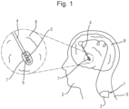
- the DBS device 1 comprises a neurostimulator 3 which generates a stimulation signal comprising stimulation pulses and processes an electrophysiological signal as described in more detail below.
- the neurostimulator 3 is connected by a lead wire 4 providing parallel electrical connection to multiple electrodes 5 (four electrodes being shown by way of example) formed on the tip 6 of the lead wire 4.
- the DBS device 1 is surgically implanted as follows.
- the tip 6 of the lead wire 4 is implanted into a target site 7 in the brain 8 of the patient 2 through a small opening in the skull of the patient.
- the target site 7 is the subthalamic nucleus (STN) for treatment of Parkinson's disease (PD), but in general the target site 7 could be another site in the brain 8 or elsewhere in the body (spinal cord, peripheral or autonomic nerves etc).
- STN subthalamic nucleus
- PD Parkinson's disease
- the neurostimulator 3 is implanted into the thorax 9 of the patient 2 near the collarbone, with the lead wire 4 extending under the skin of the patient 2.
- Fig. 3 illustrates the temporal wave form of an example of a stimulation signal 11 at a stimulation frequency of 130 Hz.
- the stimulation signal 11 comprises a pair of stimulation pulses 12 and 13 of positive and negative polarity, respectively.
- the stimulation pulses 12 and 13 each have a length of 60 ⁇ s, and have a separation of 20 ⁇ s.
- the stimulation pulses 12 and 13 have a magnitude of 3.5 V.
- the stimulation pulses 12 and 13 occur at timings controlled by a stimulation clock 14 which drives the generation of the stimulation pulses 12 and 13. At every rising-edge of the stimulation clock, the first stimulation pulse 12 of the required duration is generated, then a delay by the amount of time representing the pulse gap is introduced before generating the second stimulation pulse 13.
- the analogue antialiasing filter 25 may be a simple first order low-pass filter with a -3dB point at 4.8 kHz, which is supplemented by the digital antialiasing filter 27 of the ADC 26 which may be a sinc3 filter with a cut-off frequency of 0.27 times the sampling frequency. Where a Porti 7 system is used and configured at its maximum sampling frequency of 2048 Hz, the actual cut-off frequency of the digital antialiasing filter 27 is equal to 552.96 Hz.
- the choice of the ADC 26 is important to derive an LFP signal of good quality.
- the ADC 26 has a high resolution to obtain a sufficient vertical resolution to adequately digitise the electrophysiological signals that can be around 1 ⁇ v or less despite the different sources of noises (thermal noise from the different electronic circuits, noises generated by the power supply and switching components, and noise from the room environment), and DC biases.
- the Porti 7 system uses a 22-bit ADC (Reference 7) and, for input signals on the range of ⁇ 150 mV, its vertical resolution is 1.4305 ⁇ V with an RMS noise ⁇ 20 ⁇ V (Reference 5).
- the techniques described herein are not limited by the resolution of the ADC 26, offering high-precision neurophysiological recordings with a power consumption essentially dependant on the recording circuit technology, without saturation of the ADC 26.
- the post-processing section 22 includes a notch filter 29, a large-band band-pass filter 30 and a narrow-band band-pass filter 31 arranged in series to process the digital electrophysiological signal output from the pre-processing section 21 and thereby extract the LFP signal of interest for the specific application.
- the notch filter 29 removes the impact of mains interference (50/60 Hz) which usually remains in the electrophysiological signal despite the active shielding provided by the differential input.
- the large-band band-pass filter 30 extracts the desired portion of the LFP spectrum and is used in applications requiring the analysis of a large portion thereof.
- This filter may be implemented by cascading: a high-pass filter (HPF) to remove the DC component of the signal, typically a 4th order HPF with a cut-off frequency at around 2 Hz; and a low-pass filter (LPF) with a cut-off frequency slightly above the maximum harmonic of interest, typically a 4th order LPF with a cut-off frequency at around 95 Hz.
- HPF high-pass filter
- LPF low-pass filter
- An alternative approach is to use a band-pass filter combining the characteristics of both filters.
- the narrow-band band-pass filter 31 is particularly used in the case of closed-loop DBS since the goal is to reduce the amplitude of the beta-band peak that lies somewhere between 10 ⁇ 35 Hz but varying by patient and often being narrower than this range.
- the classical approach is to use a 4th order band-pass filter centred on the beta-band for closed-loop real-time applications, although offline post-processing is often based on wavelet analysis.
- the notch filter 29, the large-band band-pass filter 30 and a narrow-band band-pass filter 31 are thus configured to remove noise, DC-drift and extract the frequency band of interest of the digitised LFP signal.
- the closed-loop deep brain stimulation control circuit 41 supplies a primary control signal which controls the generation of the stimulation signal by the stimulation generator 40 and optionally also a waveform control signal which controls parameters of the waveform of the stimulation signal, for example the duration of each stimulation pulse, the gap between the stimulation pulses, the amplitude of the stimulation pulses, and/or the shape of the stimulation pulses.
- the primary control signal may simply turn the generation of the stimulation control signal on and off.
- Such control is implemented in the neurostimulator 3 shown in Fig. 2 by use of a selection unit 42.
- the primary control signal and the stimulation clock signal f p which controls the stimulation generator 40 to generate the stimulation pulses (as described further below) pass through the selection unit 42. Accordingly, the stimulation clock signal f p is passed when the primary control signal is high to cause operation of the stimulation generator 40 and is blocked when the primary control signal is low to cease operation of the stimulation generator 40.
- the selection unit 42 may be an AND gate.
- the waveform control signal may control the stimulation generator 40 in other ways, for example to also vary any of the parameters of the stimulation signal mentioned above.
- the artefact 51 has the same overall shape as the pair of stimulation pulses of opposite polarity and is clearly derived therefrom but is shaped by the electrophysiological properties of the brain 8.
- the artefact 51 is in fact composed of harmonics multiple of the stimulation frequency as described in more detail below.
- a low sampling frequency for example in the range from 500 Hz to 2 kHz as has often been used in DBS studies, then since the stimulation artefacts are composed of a very large range of harmonics multiple of the stimulation frequency stretching beyond the 600 kHz frequency band, the low sampling frequency could in principle lead to a widespread aliasing at frequencies different from the integer number of the stimulation frequency as shown in Figs. 11 to 13 and described in more detail below, despite the implementation of an antialiasing filter around 500 Hz. This widespread aliasing can lead to an abnormally elevated noise floor and therefore a low SNR.
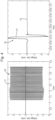
- Fig. 5 wherein the first graph shows during simultaneous stimulation and recording, the frequency spectrum of the recorded electrophysiological signal in the absence of aliasing and the second graph shows the frequency spectrum of the electrophysiological signal in the presence of aliasing leading to an elevated noise floor.
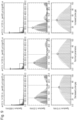
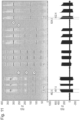
- Each of Figs. 6 to 10 is a 3 ⁇ 3 grid of graphs of frequency spectra, wherein each column contains the same frequency spectra for a given set of values of the four parameters.
- the central column in the same and corresponds to parameters of 3.5 V, 130 Hz, 60 ⁇ s pulse width and 20 ⁇ s gap, those being standard values of the parameters widely used in clinical application of DBS to treat PD.
- the left column shows the frequency spectrum when a parameter under consideration is decreased
- the right column shows the frequency spectrum when the same parameter is increased.
- the rows contain the frequency spectra with different frequency scalings and frequency ranges. In particular, the top row shows the range 0 to 600 kHz, the middle row shows the range 0 to 25 kHz, and the bottom row shows the range 0 to 10 kHz which focuses on the main spectral lobe.
- Fig. 6 shows the consequences of changing the amplitude to 1.0 V (left column) and to 5.0 V (right column).
- the most striking feature is that the spectrum has harmonics at all integer numbers of the 130 Hz stimulation clock frequency (cf. lower spectra row), multiplied by a complex sine cardinal (sync) function.
- the whole spectrum is reduced or amplified, respectively, by exactly the same factor.
- changing the amplitude does not change the shape of the spectrum since the overall shape and nodes (harmonics with an amplitude close to 0) are kept identical.
- the amplitude of the pulse has a linear relationship with the spectrum amplitude; this is not the case for other parameters as discussed further down.
- the pulse-width sets the overall 'energy' and shape of the spectrum.
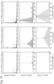
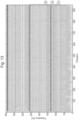
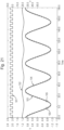
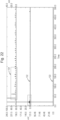
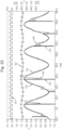
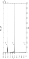
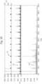
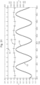
- FIG. 11 to 13 show three actual recordings from three persons with Parkinson's disease (PD) using the same neurostimulator.
- Stimulating at 60 Hz generated the expected integer harmonics (60, 120, 180 Hz and so on), but with limited aliasing elsewhere.
- stimulating at 100 Hz generated aliasing in the 250-350 Hz band (box 'd'), and 300-400 Hz band with 150 Hz stimulation (box 'e').
- the neurostimulator 3 overcomes these problems using an approach in which the generation of stimulation pulses in the stimulation generator 40 and the sampling of the electrophysiological signal by the ADC 26 are synchronised, with control of the relative phase to cause the sampling to occur outside the stimulation pulses, or in other words the conversion time (or settle time) of the ADC 26 occurs outside the stimulation pulses.
- this is achieved by a relatively simple configuration of the neurostimulator 3 to effect the synchronisation and relative delay of the sampling clock signal that is supplied to the ADC 26 and the stimulation clock signal supplied to the stimulation generator 40.
- the ADC 26 performs the sampling at timings controlled by the sampling clock signal and the stimulation generator 40 generates the stimulation pulses at timings controlled by the stimulation clock signal.
- the sampling clock signal and the stimulation clock signal are periodic square signals, and the sampling of the electrophysiological signal by the ADC 26 occurs over a conversion time (or settle time) starting at a timing of the rising edge of sampling clock signal whereas the stimulation generator 40 generates the stimulation pulses at the rising edge of the stimulation clock signal.
- control of the clock signals similarly controls the operation of the ADC 26 and the stimulation generator 40.
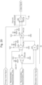
- the neurostimulator 3 includes a master clock 60 that generates a master clock signal of frequency f m and a clock signal unit 61 that derives the sampling clock signal of frequency f s and a stimulation clock signal of frequency f p therefrom.
- the master clock signal is a periodic square signal.
- the clock signal unit 61 supplies the master clock signal directly to the ADC 26 as the sampling clock signal, so the sampling clock signal is the master clock signal and the frequencies f s and f m have the same value.
- the clock signal unit 61 includes a frequency divider 63 and a delay unit 64.
- the master clock signal is supplied to the frequency divider 63.
- the frequency divider 63 frequency divides the master clock signal by a plural integer value N to derive an initial stimulation clock signal of frequency f r which has a value of f s / N which is supplied to the delay unit 64.
- the frequency divider 63 may be a modulo-A frequency divider.
- the delay unit 64 delays the first stimulation clock signal to derive the stimulation clock signal of frequency f p which has the same value as frequency f r .
- the value of the delay time D t as at least the time the ADC 26 requires to fully complete the analogue-to-digital conversion for example being of the order 10 ⁇ s to 20 ⁇ s in a standard ADC, or being less than 1 ⁇ s in a faster ADC. It should be noted however that the delay is not of absolute necessity for the proper functioning of the proposed solution; it represents a safeguard to guaranty that the ADC circuit 26 never sees at its inputs the artefact whiles performing the actual digital conversion.
- the sampling clock signal and the stimulation clock signal are intrinsically synchronised because they are both derived from the master clock signal. Also, a relative delay between the sampling clock signal and the stimulation clock signal is introduced, in this example by the delay unit 64 delaying the initial stimulation clock signal, i.e. after performing the frequency dividing.
- the relative delay between the sampling clock signal and the stimulation clock signal may be introduced by arranging the delay unit 26 at other locations.
- Figs. 14 and 15 show alternative forms of the clock signal unit 61. In each case, the sampling clock signal and the stimulation clock signal are derived from the master clock signal in a similar manner and so are synchronised.
- the delay unit 64 is arranged to delay the master clock signal before supply to the frequency divider 63 to derive the stimulation clock signal.
- the relative delay is introduced by arranging the delay unit 64 to delay the clock signal obtain from the frequency divider 63 to derive the stimulation clock signal.
- the magnitude of the delay introduced by the delay unit 64 in Fig. 15 is different from the case of Figs. 2 and 14 because the clock signal from the frequency divider 63 is delayed.
- the clock signal unit 61 implements this control in a simple manner requiring minimal electronics.
- the clock signal unit 61 may be implemented at the software level of the neurostimulator 3.
- the relative delay has been selected so that the timing 73 of one sample occurs just before a stimulation pulse is delivered, so that the artefact 71 has ended by the timing 73 of the next sample as per Nyquist-Shannon rule.
- the timing 73 is illustrated as a point for clarity.
- the sampling has a conversion time (or settle time) over which sampling occurs, and the delay is selected so that the entire conversion time is outside the stimulation pulse and resultant artefact 71.
- the sampling frequency f s is an integer multiple of the stimulation frequency f p and so is set by the desired stimulation frequency and the plural integer value N of the frequency divider 63.
- the plural integer value N is set to be high enough to enable the sampling frequency to provide coverage of the full bandwidth of the electrophysiological signal without aliasing components, while maintaining the effect of avoiding artefacts from the stimulation signal.
- the plural integer value N is at least one. For example, if the stimulation frequency takes a typical value of 130 Hz, then a plural integer of four provides a sampling frequency of 520 Hz, providing sampling of a bandwidth up to 260 Hz which is suitable for deriving the LPF signal for closed-loop DBS for the treatment of Parkinson's disease.
- the total required time for the above illustration will be 370 ⁇ s (250 ⁇ s of settle time plus 120 ⁇ s of pulse duration).
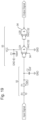
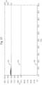
- Fig. 17 shows a typical chronogram for these parameters of the first illustrative example (when using the example above labelled fast ADC) showing the master clock signal 80 which is also the sampling clock signal, the initial stimulation clock signal 81 output by the frequency divider 63, the stimulation clock signal 82 output by the delay unit 64, the stimulation signal 83 comprising a pair of stimulation pulses 84 and 85, and the resultant artefact 86.
- the master clock signal 80 is a square wave at the sampling frequency f s of 7.02 kHz.
- neurostimulator 3 Another important feature of the neurostimulator 3 is that the synchronisation and relative delay can be fully implemented either by software code or with basic electronic components.
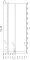
- Fig. 18 shows an example of the implementation of the frequency divider 63 arranged as follows.
- the frequency divider 63 includes a programmable divide-by-N counter 90 to which the master clock signal is fed.
- the frequency divider 63, delay unit 64 and selection unit 42 were implemented as shown in Figs. 18 to 20 .
- the stimulation generator 40 was implemented via a proprietary device capable of delivering a stimulation pulse at each rising edge of the stimulation clock signal. This device allowed the four parameters of the generated pulse, namely amplitude, frequency, pulse-width and pulse-gap to be set independently.
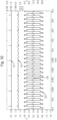
- the discretised input 103 by the ADC 26 presented the expected stair-like effect due to digital conversion. However, one can see that some larger discretised values (“glitches”) that do not correspond to the actual analogue input (see the black circles 105 in Fig. 21 ). Those "glitches" are due the harmonics present in the ⁇ sinewave' input (generated digitally), and also to the background noise that was measured to be up to ⁇ 60 mV.
- a second approach to deal with the electrode polarisation is to use a fast-response non-oscillatory digital filter after the synchronised sensing.
- the apparatus may be adapted to other scenarios where closed-loop stimulation of a target area of a human or animal body is performed, including neuroscience applications and more generally bioengineering applications as discussed above.
- Some specific but non-limitative examples are closed-loop spinal cord stimulation (for example as disclosed in Reference 28), peripheral or autonomic nerve stimulation (for example as disclosed in Reference 29), or closed-loop non-invasive brain stimulation (for example as disclosed in Reference 30).
- Another example is the emerging domain of sonic neuromodulation, where an ultrasound signal is used to modulate the brain activity. In this example, even if the stimulation modality is ultrasound, it still generates large electrical artefact due the well-established effect of electromechanical coupling in neurons.
- the apparatus may be adapted for in any application where stimulation generates artefacts in the recorded signal, whereas the stimulation and recording modalities do not need to be the same.
- a sample-and-hold circuit may be added before the ADC to define the conversion time to assist in arranging the conversion time outside of the stimulation pulses.
- a last aspect to be taken into consideration is the mode to which data are send by the ADC.
- ADCs usually two conversion modes can be found (very often to be chosen from the same ADC circuit): a continuous conversion mode where the digital data are 'streamed' continuously and indefinitely after the start conversion signal or command is sent to the ADC, and until a stop signal or command is sent to the ADC.
- a single conversion is performed after the start signal or command, and the ADC waits then the next one in order to perform another conversion.
- the DBS device 1 has an advantage of scalability. That is, the DBS device 1 can be easily scaled to 1000 or more recording channels by simply using the same synchronisation circuit for all recorders, with almost no further power cost whatsoever. For instance, the DBS device 1 can be scaled efficiently by using a single ADC and by multiplexing its inputs to record from both hemispheres or shared with multiple electrodes.
Landscapes
- Health & Medical Sciences (AREA)
- Life Sciences & Earth Sciences (AREA)
- Animal Behavior & Ethology (AREA)
- General Health & Medical Sciences (AREA)
- Biomedical Technology (AREA)
- Nuclear Medicine, Radiotherapy & Molecular Imaging (AREA)
- Radiology & Medical Imaging (AREA)
- Neurosurgery (AREA)
- Neurology (AREA)
- Engineering & Computer Science (AREA)
- Public Health (AREA)
- Veterinary Medicine (AREA)
- Biophysics (AREA)
- Physiology (AREA)
- Electrotherapy Devices (AREA)
- Measurement And Recording Of Electrical Phenomena And Electrical Characteristics Of The Living Body (AREA)
Claims (7)
- Stimulationsvorrichtung (3), umfassend:einen Stimulationsgenerator (40), der angeordnet ist, um ein Stimulationssignal zu generieren, umfassend Stimulationsimpulse zum Stimulieren eines Zielbereichs (7) eines Menschen- oder Tierkörpers; undeinen Analog-Digital-Wandler (26), der angeordnet ist, um eine Probe von einem elektrophysiologischen Signal zu nehmen, das vom Körper gemessen wird, um ein digitales elektrophysiologisches Signal zum Ableiten eines Rückkopplungssignals für Regelung des Stimulationssignals zu generieren,dadurch gekennzeichnet, dass:eine Probenahmehäufigkeit, mit der der Analog-Digital-Wandler (26) angeordnet ist, eine Probe von dem elektrophysiologischen Signal zu nehmen, ein positiver Ganzzahlwert mal eine Stimulationsfrequenz ist, mit der der Stimulationsgenerator (40) angeordnet ist, um die Stimulationsimpulse zu generieren; unddie Vorrichtung (3) angeordnet ist, sodass die Generierung von Stimulationssignal und die Probenahme des elektrophysiologischen Signals durch den Analog-Digital-Wandler (26) synchronisiert sind und eine relative Phase aufweisen, die ausgewählt ist, um zu verursachen, dass die Probenahme außerhalb der Stimulationsimpulse auftritt.
- Stimulationsvorrichtung (3) nach Anspruch 1, wobei der positive Ganzzahlwert ein pluraler Ganzzahlwert ist, wobei optional der plurale Ganzzahlwert mindestens vier ist.
- Stimulationsvorrichtung (3) nach Anspruch 1 oder 2, wobei die Vorrichtung (3) Folgendes umfasst:einen Haupttaktgeber (60), der angeordnet ist, um ein Haupttaktsignal zu generieren; undeine Taktsignaleinheit (61), die angeordnet ist, um ein Probenahmetaktsignal und ein Stimulationstaktsignal synchron von dem Haupttaktsignal abzuleiten, mit einer relativen Verzögerung, die zwischen dem Probenahmetaktsignal und dem Stimulationstaktsignal eingeführt wird, um ihre relative Phase anzupassen, wobei die Schaltung das Probenahmetaktsignal dem Analog-Digital-Wandler (26) zuführt und das Stimulationstaktsignal dem Stimulationsgenerator (40) zuführt,wobei der Analog-Digital-Wandler (26) angeordnet ist, um die Probenahme zu Zeiten durchzuführen, die durch das Probenahmetaktsignal gesteuert werden, und der Stimulationsgenerator (40) angeordnet ist, um die Stimulationsimpulse zu Zeiten zu generieren, die durch das Stimulationstaktsignal gesteuert werden.
- Stimulationsvorrichtung (3) nach Anspruch 3, wobei das Probenahmetaktsignal das Haupttaktsignal ist und/oder die Taktsignaleinheit (61) angeordnet ist, um das Stimulationstaktsignal durch Frequenzteilen des Haupttaktsignals durch einen pluralen Ganzzahlwert abzuleiten.
- Stimulationsvorrichtung (3) nach Anspruch 3 oder 4, wobei die Taktsignaleinheit (61) angeordnet ist, um die relative Verzögerung zwischen dem Probenahmetaktsignal und dem Stimulationstaktsignal durch Verzögern des Stimulationstaktsignals nach Durchführen des Frequenzteilens oder durch Verzögern des Probenahmetaktsignals einzuführen.
- Stimulationsvorrichtung (3) nach einem der Ansprüche 1 bis 5, ferner umfassend eine Verarbeitungsschaltung (20), die angeordnet ist, um ein Rückkopplungssignal von dem digitalen elektrophysiologischen Signal abzuleiten, und eine Regelschaltung (41), die angeordnet ist, um den Betrieb des Stimulationsgenerators (40) basierend auf dem Rückkopplungssignal zu steuern.
- Stimulationsvorrichtung (3) nach einem der Ansprüche 1 bis 6, ferner umfassend Elektroden (5), die mit dem Stimulationssignal zugeführt werden und von denen das elektrophysiologische Signal zugeführt wird.
Applications Claiming Priority (2)
| Application Number | Priority Date | Filing Date | Title |
|---|---|---|---|
| GB201816141 | 2018-10-03 | ||
| PCT/GB2019/052777 WO2020070492A1 (en) | 2018-10-03 | 2019-10-02 | Measurement of electrophysiological signals during stimulation of a target area of a body |
Publications (2)
| Publication Number | Publication Date |
|---|---|
| EP3860705A1 EP3860705A1 (de) | 2021-08-11 |
| EP3860705B1 true EP3860705B1 (de) | 2024-07-03 |
Family
ID=68242721
Family Applications (1)
| Application Number | Title | Priority Date | Filing Date |
|---|---|---|---|
| EP19787361.5A Active EP3860705B1 (de) | 2018-10-03 | 2019-10-02 | Messung von elektrophysiologischen signalen während der stimulation eines zielbereichs eines körpers |
Country Status (3)
| Country | Link |
|---|---|
| US (1) | US12036411B2 (de) |
| EP (1) | EP3860705B1 (de) |
| WO (1) | WO2020070492A1 (de) |
Families Citing this family (5)
| Publication number | Priority date | Publication date | Assignee | Title |
|---|---|---|---|---|
| WO2021067873A1 (en) * | 2019-10-04 | 2021-04-08 | Nalu Medical, Inc. | Stimulation apparatus |
| CN113940689B (zh) * | 2021-09-14 | 2023-05-05 | 复旦大学 | 一种闭环深部脑刺激伪迹抑制系统 |
| CN116407756A (zh) * | 2021-12-29 | 2023-07-11 | 精能医学股份有限公司 | 判断电刺激信号品质的方法、电刺激装置和电脑可读存储媒体 |
| US20230397872A1 (en) * | 2022-06-08 | 2023-12-14 | Zoll Medical Corporation | Systems and methods for determining electrode-skin contact using signal undersampling |
| WO2024020455A1 (en) * | 2022-07-19 | 2024-01-25 | Wavegate Corporation | Feed forward control system for a spinal cord stimulation system and method of use |
Family Cites Families (7)
| Publication number | Priority date | Publication date | Assignee | Title |
|---|---|---|---|---|
| US7292168B2 (en) * | 2005-12-28 | 2007-11-06 | Medtronic, Inc. | DSP with variable sample frequency |
| US8295934B2 (en) | 2006-11-14 | 2012-10-23 | Neurovista Corporation | Systems and methods of reducing artifact in neurological stimulation systems |
| US9248280B2 (en) | 2007-11-02 | 2016-02-02 | Boston Scientific Neuromodulation Corporation | Closed-loop feedback for steering stimulation energy within tissue |
| US9399132B2 (en) | 2009-06-30 | 2016-07-26 | Boston Scientific Neuromodulation Corporation | Method and device for acquiring physiological data during tissue stimulation procedure |
| US9421375B2 (en) * | 2013-10-28 | 2016-08-23 | Biotronik Se & Co. Kg | Sensing unit for a tissue stimulator |
| EP4230133B1 (de) * | 2015-10-21 | 2025-09-17 | Autonomix Medical, Inc. | Kontrollierte und präzise behandlung von herzgeweben |
| US20180199841A1 (en) | 2017-01-19 | 2018-07-19 | Regents Of The University Of Minnesota | System and method for simultaneous stimulation and recording using system-on-chip (soc) architecture |
-
2019
- 2019-10-02 EP EP19787361.5A patent/EP3860705B1/de active Active
- 2019-10-02 US US17/282,133 patent/US12036411B2/en active Active
- 2019-10-02 WO PCT/GB2019/052777 patent/WO2020070492A1/en not_active Ceased
Also Published As
| Publication number | Publication date |
|---|---|
| US12036411B2 (en) | 2024-07-16 |
| WO2020070492A1 (en) | 2020-04-09 |
| EP3860705A1 (de) | 2021-08-11 |
| US20210370070A1 (en) | 2021-12-02 |
Similar Documents
| Publication | Publication Date | Title |
|---|---|---|
| EP3860705B1 (de) | Messung von elektrophysiologischen signalen während der stimulation eines zielbereichs eines körpers | |
| Zhou et al. | Toward true closed-loop neuromodulation: artifact-free recording during stimulation | |
| US12064628B2 (en) | Apparatus for treating neurological disorders by electrostimulation and method for processing neural signals collected by the said apparatus | |
| Shin et al. | NeuralTree: A 256-channel 0.227-μJ/class versatile neural activity classification and closed-loop neuromodulation SoC | |
| Qian et al. | A method for removal of deep brain stimulation artifact from local field potentials | |
| Greenwald et al. | A bidirectional neural interface IC with chopper stabilized BioADC array and charge balanced stimulator | |
| Johnson et al. | An implantable 700μW 64-channel neuromodulation IC for simultaneous recording and stimulation with rapid artifact recovery | |
| Culaclii et al. | Online artifact cancelation in same-electrode neural stimulation and recording using a combined hardware and software architecture | |
| CN118873841B (zh) | 基于多模态数据的经颅电刺激装置及系统 | |
| Debarros et al. | Artefact-free recording of local field potentials with simultaneous stimulation for closed-loop deep-brain stimulation | |
| Limnuson et al. | A bidirectional neural interface SoC with an integrated spike recorder, microstimulator, and low-power processor for real-time stimulus artifact rejection | |
| Shin et al. | A 16-channel low-power neural connectivity extraction and phase-locked deep brain stimulation SoC | |
| Huang et al. | A CMOS synchronized sample-and-hold artifact blanking analog front-end local field potential acquisition unit with±3.6-V stimulation artifact tolerance and monopolar electrode-tissue impedance measurement circuit for closed-loop deep brain stimulation SoCs | |
| Chu et al. | Equalization for intracortical microstimulation artifact reduction | |
| Zhou et al. | Wand: a 128-channel, closed-loop, wireless artifact-free neuromodulation device | |
| Sellers et al. | Comparison of common artifact rejection methods applied to direct cortical and peripheral stimulation in human ECoG | |
| CN113577561B (zh) | 一种微电流刺激诱导精神状态的方法和装置 | |
| Ghani et al. | Detection of wrist movement using EEG signal for brain machine interface | |
| Azin et al. | An activity-dependent brain microstimulation SoC with integrated 23nV/rtHz neural recording front-end and 750nW spike discrimination processor | |
| CN118868944B (zh) | 用于神经刺激器的低功耗自适应斩波放大采样方法及装置、存储介质与终端 | |
| Cao et al. | Design of a Savitzky-Golay Filter-Based vEMG-FES System | |
| Wu et al. | Stimulation-Induced Artifact Removal of the Local Field Potential Through Hardware Design: Toward the Implantable Closed-Loop Deep Brain Stimulation | |
| Liu et al. | A Novel Stimulus Artifact Suppression System With Fast Template Subtraction | |
| WO2024072696A1 (en) | System and method for detrending stimulation artifacts in neuromodulation systems | |
| Schoenecker et al. | Fast stimulus artifact recovery in a multichannel neural recording system |
Legal Events
| Date | Code | Title | Description |
|---|---|---|---|
| STAA | Information on the status of an ep patent application or granted ep patent |
Free format text: STATUS: UNKNOWN |
|
| STAA | Information on the status of an ep patent application or granted ep patent |
Free format text: STATUS: THE INTERNATIONAL PUBLICATION HAS BEEN MADE |
|
| PUAI | Public reference made under article 153(3) epc to a published international application that has entered the european phase |
Free format text: ORIGINAL CODE: 0009012 |
|
| STAA | Information on the status of an ep patent application or granted ep patent |
Free format text: STATUS: REQUEST FOR EXAMINATION WAS MADE |
|
| 17P | Request for examination filed |
Effective date: 20210420 |
|
| AK | Designated contracting states |
Kind code of ref document: A1 Designated state(s): AL AT BE BG CH CY CZ DE DK EE ES FI FR GB GR HR HU IE IS IT LI LT LU LV MC MK MT NL NO PL PT RO RS SE SI SK SM TR |
|
| DAV | Request for validation of the european patent (deleted) | ||
| DAX | Request for extension of the european patent (deleted) | ||
| STAA | Information on the status of an ep patent application or granted ep patent |
Free format text: STATUS: EXAMINATION IS IN PROGRESS |
|
| 17Q | First examination report despatched |
Effective date: 20230321 |
|
| GRAP | Despatch of communication of intention to grant a patent |
Free format text: ORIGINAL CODE: EPIDOSNIGR1 |
|
| STAA | Information on the status of an ep patent application or granted ep patent |
Free format text: STATUS: GRANT OF PATENT IS INTENDED |
|
| INTG | Intention to grant announced |
Effective date: 20240129 |
|
| GRAS | Grant fee paid |
Free format text: ORIGINAL CODE: EPIDOSNIGR3 |
|
| GRAA | (expected) grant |
Free format text: ORIGINAL CODE: 0009210 |
|
| STAA | Information on the status of an ep patent application or granted ep patent |
Free format text: STATUS: THE PATENT HAS BEEN GRANTED |
|
| P01 | Opt-out of the competence of the unified patent court (upc) registered |
Effective date: 20240507 |
|
| AK | Designated contracting states |
Kind code of ref document: B1 Designated state(s): AL AT BE BG CH CY CZ DE DK EE ES FI FR GB GR HR HU IE IS IT LI LT LU LV MC MK MT NL NO PL PT RO RS SE SI SK SM TR |
|
| REG | Reference to a national code |
Ref country code: CH Ref legal event code: EP |
|
| REG | Reference to a national code |
Ref country code: DE Ref legal event code: R096 Ref document number: 602019054657 Country of ref document: DE |
|
| REG | Reference to a national code |
Ref country code: LT Ref legal event code: MG9D |
|
| REG | Reference to a national code |
Ref country code: NL Ref legal event code: MP Effective date: 20240703 |
|
| PG25 | Lapsed in a contracting state [announced via postgrant information from national office to epo] |
Ref country code: PT Free format text: LAPSE BECAUSE OF FAILURE TO SUBMIT A TRANSLATION OF THE DESCRIPTION OR TO PAY THE FEE WITHIN THE PRESCRIBED TIME-LIMIT Effective date: 20241104 |
|
| REG | Reference to a national code |
Ref country code: AT Ref legal event code: MK05 Ref document number: 1699178 Country of ref document: AT Kind code of ref document: T Effective date: 20240703 |
|
| PG25 | Lapsed in a contracting state [announced via postgrant information from national office to epo] |
Ref country code: NL Free format text: LAPSE BECAUSE OF FAILURE TO SUBMIT A TRANSLATION OF THE DESCRIPTION OR TO PAY THE FEE WITHIN THE PRESCRIBED TIME-LIMIT Effective date: 20240703 |
|
| PG25 | Lapsed in a contracting state [announced via postgrant information from national office to epo] |
Ref country code: PT Free format text: LAPSE BECAUSE OF FAILURE TO SUBMIT A TRANSLATION OF THE DESCRIPTION OR TO PAY THE FEE WITHIN THE PRESCRIBED TIME-LIMIT Effective date: 20241104 Ref country code: NL Free format text: LAPSE BECAUSE OF FAILURE TO SUBMIT A TRANSLATION OF THE DESCRIPTION OR TO PAY THE FEE WITHIN THE PRESCRIBED TIME-LIMIT Effective date: 20240703 |
|
| PGFP | Annual fee paid to national office [announced via postgrant information from national office to epo] |
Ref country code: DE Payment date: 20241022 Year of fee payment: 6 |
|
| PG25 | Lapsed in a contracting state [announced via postgrant information from national office to epo] |
Ref country code: NO Free format text: LAPSE BECAUSE OF FAILURE TO SUBMIT A TRANSLATION OF THE DESCRIPTION OR TO PAY THE FEE WITHIN THE PRESCRIBED TIME-LIMIT Effective date: 20241003 |
|
| PG25 | Lapsed in a contracting state [announced via postgrant information from national office to epo] |
Ref country code: FI Free format text: LAPSE BECAUSE OF FAILURE TO SUBMIT A TRANSLATION OF THE DESCRIPTION OR TO PAY THE FEE WITHIN THE PRESCRIBED TIME-LIMIT Effective date: 20240703 Ref country code: GR Free format text: LAPSE BECAUSE OF FAILURE TO SUBMIT A TRANSLATION OF THE DESCRIPTION OR TO PAY THE FEE WITHIN THE PRESCRIBED TIME-LIMIT Effective date: 20241004 Ref country code: PL Free format text: LAPSE BECAUSE OF FAILURE TO SUBMIT A TRANSLATION OF THE DESCRIPTION OR TO PAY THE FEE WITHIN THE PRESCRIBED TIME-LIMIT Effective date: 20240703 |
|
| PG25 | Lapsed in a contracting state [announced via postgrant information from national office to epo] |
Ref country code: BG Free format text: LAPSE BECAUSE OF FAILURE TO SUBMIT A TRANSLATION OF THE DESCRIPTION OR TO PAY THE FEE WITHIN THE PRESCRIBED TIME-LIMIT Effective date: 20240703 |
|
| PG25 | Lapsed in a contracting state [announced via postgrant information from national office to epo] |
Ref country code: LV Free format text: LAPSE BECAUSE OF FAILURE TO SUBMIT A TRANSLATION OF THE DESCRIPTION OR TO PAY THE FEE WITHIN THE PRESCRIBED TIME-LIMIT Effective date: 20240703 |
|
| PG25 | Lapsed in a contracting state [announced via postgrant information from national office to epo] |
Ref country code: IS Free format text: LAPSE BECAUSE OF FAILURE TO SUBMIT A TRANSLATION OF THE DESCRIPTION OR TO PAY THE FEE WITHIN THE PRESCRIBED TIME-LIMIT Effective date: 20241103 Ref country code: AT Free format text: LAPSE BECAUSE OF FAILURE TO SUBMIT A TRANSLATION OF THE DESCRIPTION OR TO PAY THE FEE WITHIN THE PRESCRIBED TIME-LIMIT Effective date: 20240703 |
|
| PG25 | Lapsed in a contracting state [announced via postgrant information from national office to epo] |
Ref country code: HR Free format text: LAPSE BECAUSE OF FAILURE TO SUBMIT A TRANSLATION OF THE DESCRIPTION OR TO PAY THE FEE WITHIN THE PRESCRIBED TIME-LIMIT Effective date: 20240703 Ref country code: CZ Free format text: LAPSE BECAUSE OF FAILURE TO SUBMIT A TRANSLATION OF THE DESCRIPTION OR TO PAY THE FEE WITHIN THE PRESCRIBED TIME-LIMIT Effective date: 20240703 |
|
| PG25 | Lapsed in a contracting state [announced via postgrant information from national office to epo] |
Ref country code: ES Free format text: LAPSE BECAUSE OF FAILURE TO SUBMIT A TRANSLATION OF THE DESCRIPTION OR TO PAY THE FEE WITHIN THE PRESCRIBED TIME-LIMIT Effective date: 20240703 Ref country code: RS Free format text: LAPSE BECAUSE OF FAILURE TO SUBMIT A TRANSLATION OF THE DESCRIPTION OR TO PAY THE FEE WITHIN THE PRESCRIBED TIME-LIMIT Effective date: 20241003 |
|
| PG25 | Lapsed in a contracting state [announced via postgrant information from national office to epo] |
Ref country code: RS Free format text: LAPSE BECAUSE OF FAILURE TO SUBMIT A TRANSLATION OF THE DESCRIPTION OR TO PAY THE FEE WITHIN THE PRESCRIBED TIME-LIMIT Effective date: 20241003 Ref country code: PL Free format text: LAPSE BECAUSE OF FAILURE TO SUBMIT A TRANSLATION OF THE DESCRIPTION OR TO PAY THE FEE WITHIN THE PRESCRIBED TIME-LIMIT Effective date: 20240703 Ref country code: NO Free format text: LAPSE BECAUSE OF FAILURE TO SUBMIT A TRANSLATION OF THE DESCRIPTION OR TO PAY THE FEE WITHIN THE PRESCRIBED TIME-LIMIT Effective date: 20241003 Ref country code: LV Free format text: LAPSE BECAUSE OF FAILURE TO SUBMIT A TRANSLATION OF THE DESCRIPTION OR TO PAY THE FEE WITHIN THE PRESCRIBED TIME-LIMIT Effective date: 20240703 Ref country code: IS Free format text: LAPSE BECAUSE OF FAILURE TO SUBMIT A TRANSLATION OF THE DESCRIPTION OR TO PAY THE FEE WITHIN THE PRESCRIBED TIME-LIMIT Effective date: 20241103 Ref country code: HR Free format text: LAPSE BECAUSE OF FAILURE TO SUBMIT A TRANSLATION OF THE DESCRIPTION OR TO PAY THE FEE WITHIN THE PRESCRIBED TIME-LIMIT Effective date: 20240703 Ref country code: GR Free format text: LAPSE BECAUSE OF FAILURE TO SUBMIT A TRANSLATION OF THE DESCRIPTION OR TO PAY THE FEE WITHIN THE PRESCRIBED TIME-LIMIT Effective date: 20241004 Ref country code: FI Free format text: LAPSE BECAUSE OF FAILURE TO SUBMIT A TRANSLATION OF THE DESCRIPTION OR TO PAY THE FEE WITHIN THE PRESCRIBED TIME-LIMIT Effective date: 20240703 Ref country code: ES Free format text: LAPSE BECAUSE OF FAILURE TO SUBMIT A TRANSLATION OF THE DESCRIPTION OR TO PAY THE FEE WITHIN THE PRESCRIBED TIME-LIMIT Effective date: 20240703 Ref country code: CZ Free format text: LAPSE BECAUSE OF FAILURE TO SUBMIT A TRANSLATION OF THE DESCRIPTION OR TO PAY THE FEE WITHIN THE PRESCRIBED TIME-LIMIT Effective date: 20240703 Ref country code: BG Free format text: LAPSE BECAUSE OF FAILURE TO SUBMIT A TRANSLATION OF THE DESCRIPTION OR TO PAY THE FEE WITHIN THE PRESCRIBED TIME-LIMIT Effective date: 20240703 Ref country code: AT Free format text: LAPSE BECAUSE OF FAILURE TO SUBMIT A TRANSLATION OF THE DESCRIPTION OR TO PAY THE FEE WITHIN THE PRESCRIBED TIME-LIMIT Effective date: 20240703 |
|
| REG | Reference to a national code |
Ref country code: DE Ref legal event code: R097 Ref document number: 602019054657 Country of ref document: DE |
|
| PG25 | Lapsed in a contracting state [announced via postgrant information from national office to epo] |
Ref country code: SM Free format text: LAPSE BECAUSE OF FAILURE TO SUBMIT A TRANSLATION OF THE DESCRIPTION OR TO PAY THE FEE WITHIN THE PRESCRIBED TIME-LIMIT Effective date: 20240703 Ref country code: DK Free format text: LAPSE BECAUSE OF FAILURE TO SUBMIT A TRANSLATION OF THE DESCRIPTION OR TO PAY THE FEE WITHIN THE PRESCRIBED TIME-LIMIT Effective date: 20240703 Ref country code: RO Free format text: LAPSE BECAUSE OF FAILURE TO SUBMIT A TRANSLATION OF THE DESCRIPTION OR TO PAY THE FEE WITHIN THE PRESCRIBED TIME-LIMIT Effective date: 20240703 |
|
| PG25 | Lapsed in a contracting state [announced via postgrant information from national office to epo] |
Ref country code: EE Free format text: LAPSE BECAUSE OF FAILURE TO SUBMIT A TRANSLATION OF THE DESCRIPTION OR TO PAY THE FEE WITHIN THE PRESCRIBED TIME-LIMIT Effective date: 20240703 |
|
| PG25 | Lapsed in a contracting state [announced via postgrant information from national office to epo] |
Ref country code: SK Free format text: LAPSE BECAUSE OF FAILURE TO SUBMIT A TRANSLATION OF THE DESCRIPTION OR TO PAY THE FEE WITHIN THE PRESCRIBED TIME-LIMIT Effective date: 20240703 Ref country code: IT Free format text: LAPSE BECAUSE OF FAILURE TO SUBMIT A TRANSLATION OF THE DESCRIPTION OR TO PAY THE FEE WITHIN THE PRESCRIBED TIME-LIMIT Effective date: 20240703 |
|
| PLBE | No opposition filed within time limit |
Free format text: ORIGINAL CODE: 0009261 |
|
| STAA | Information on the status of an ep patent application or granted ep patent |
Free format text: STATUS: NO OPPOSITION FILED WITHIN TIME LIMIT |
|
| REG | Reference to a national code |
Ref country code: CH Ref legal event code: PL |
|
| 26N | No opposition filed |
Effective date: 20250404 |
|
| PG25 | Lapsed in a contracting state [announced via postgrant information from national office to epo] |
Ref country code: MC Free format text: LAPSE BECAUSE OF FAILURE TO SUBMIT A TRANSLATION OF THE DESCRIPTION OR TO PAY THE FEE WITHIN THE PRESCRIBED TIME-LIMIT Effective date: 20240703 |
|
| PG25 | Lapsed in a contracting state [announced via postgrant information from national office to epo] |
Ref country code: BE Free format text: LAPSE BECAUSE OF NON-PAYMENT OF DUE FEES Effective date: 20241031 Ref country code: LU Free format text: LAPSE BECAUSE OF NON-PAYMENT OF DUE FEES Effective date: 20241002 |
|
| PG25 | Lapsed in a contracting state [announced via postgrant information from national office to epo] |
Ref country code: CH Free format text: LAPSE BECAUSE OF NON-PAYMENT OF DUE FEES Effective date: 20241031 |
|
| REG | Reference to a national code |
Ref country code: BE Ref legal event code: MM Effective date: 20241031 |
|
| PG25 | Lapsed in a contracting state [announced via postgrant information from national office to epo] |
Ref country code: SE Free format text: LAPSE BECAUSE OF FAILURE TO SUBMIT A TRANSLATION OF THE DESCRIPTION OR TO PAY THE FEE WITHIN THE PRESCRIBED TIME-LIMIT Effective date: 20240703 |
|
| PGFP | Annual fee paid to national office [announced via postgrant information from national office to epo] |
Ref country code: GB Payment date: 20250923 Year of fee payment: 7 |
|
| PGFP | Annual fee paid to national office [announced via postgrant information from national office to epo] |
Ref country code: FR Payment date: 20250925 Year of fee payment: 7 |
|
| PG25 | Lapsed in a contracting state [announced via postgrant information from national office to epo] |
Ref country code: IE Free format text: LAPSE BECAUSE OF NON-PAYMENT OF DUE FEES Effective date: 20241002 |