EP3860295A1 - Procédé d'envoi de signal, et procédé et dispositif de réception de signal - Google Patents
Procédé d'envoi de signal, et procédé et dispositif de réception de signal Download PDFInfo
- Publication number
- EP3860295A1 EP3860295A1 EP18935975.5A EP18935975A EP3860295A1 EP 3860295 A1 EP3860295 A1 EP 3860295A1 EP 18935975 A EP18935975 A EP 18935975A EP 3860295 A1 EP3860295 A1 EP 3860295A1
- Authority
- EP
- European Patent Office
- Prior art keywords
- cell
- beam failure
- failure recovery
- uplink signal
- signaling
- Prior art date
- Legal status (The legal status is an assumption and is not a legal conclusion. Google has not performed a legal analysis and makes no representation as to the accuracy of the status listed.)
- Granted
Links
- 238000000034 method Methods 0.000 title claims abstract description 100
- 238000011084 recovery Methods 0.000 claims abstract description 294
- 230000005540 biological transmission Effects 0.000 claims abstract description 153
- 230000008054 signal transmission Effects 0.000 claims abstract description 33
- 230000011664 signaling Effects 0.000 claims description 257
- 230000004913 activation Effects 0.000 claims description 105
- 230000004044 response Effects 0.000 claims description 41
- 230000000694 effects Effects 0.000 claims description 19
- 230000008569 process Effects 0.000 claims description 14
- 239000013589 supplement Substances 0.000 description 165
- 238000004891 communication Methods 0.000 description 32
- 238000010586 diagram Methods 0.000 description 26
- 230000006870 function Effects 0.000 description 12
- 238000012986 modification Methods 0.000 description 4
- 230000004048 modification Effects 0.000 description 4
- 238000005259 measurement Methods 0.000 description 3
- 101000741965 Homo sapiens Inactive tyrosine-protein kinase PRAG1 Proteins 0.000 description 2
- 102100038659 Inactive tyrosine-protein kinase PRAG1 Human genes 0.000 description 2
- 230000000712 assembly Effects 0.000 description 2
- 238000000429 assembly Methods 0.000 description 2
- 239000000969 carrier Substances 0.000 description 2
- 230000007774 longterm Effects 0.000 description 2
- 230000009897 systematic effect Effects 0.000 description 2
- 230000008901 benefit Effects 0.000 description 1
- 230000001413 cellular effect Effects 0.000 description 1
- 238000004590 computer program Methods 0.000 description 1
- 230000009977 dual effect Effects 0.000 description 1
- 238000005516 engineering process Methods 0.000 description 1
- 230000010365 information processing Effects 0.000 description 1
- 238000012544 monitoring process Methods 0.000 description 1
- 238000012545 processing Methods 0.000 description 1
- 230000002123 temporal effect Effects 0.000 description 1
- 238000012546 transfer Methods 0.000 description 1
Images


Classifications
-
- H—ELECTRICITY
- H04—ELECTRIC COMMUNICATION TECHNIQUE
- H04B—TRANSMISSION
- H04B7/00—Radio transmission systems, i.e. using radiation field
- H04B7/02—Diversity systems; Multi-antenna system, i.e. transmission or reception using multiple antennas
- H04B7/04—Diversity systems; Multi-antenna system, i.e. transmission or reception using multiple antennas using two or more spaced independent antennas
- H04B7/08—Diversity systems; Multi-antenna system, i.e. transmission or reception using multiple antennas using two or more spaced independent antennas at the receiving station
- H04B7/0868—Hybrid systems, i.e. switching and combining
- H04B7/088—Hybrid systems, i.e. switching and combining using beam selection
-
- H—ELECTRICITY
- H04—ELECTRIC COMMUNICATION TECHNIQUE
- H04B—TRANSMISSION
- H04B7/00—Radio transmission systems, i.e. using radiation field
- H04B7/02—Diversity systems; Multi-antenna system, i.e. transmission or reception using multiple antennas
- H04B7/04—Diversity systems; Multi-antenna system, i.e. transmission or reception using multiple antennas using two or more spaced independent antennas
- H04B7/0404—Diversity systems; Multi-antenna system, i.e. transmission or reception using multiple antennas using two or more spaced independent antennas the mobile station comprising multiple antennas, e.g. to provide uplink diversity
-
- H—ELECTRICITY
- H04—ELECTRIC COMMUNICATION TECHNIQUE
- H04B—TRANSMISSION
- H04B7/00—Radio transmission systems, i.e. using radiation field
- H04B7/02—Diversity systems; Multi-antenna system, i.e. transmission or reception using multiple antennas
- H04B7/04—Diversity systems; Multi-antenna system, i.e. transmission or reception using multiple antennas using two or more spaced independent antennas
- H04B7/06—Diversity systems; Multi-antenna system, i.e. transmission or reception using multiple antennas using two or more spaced independent antennas at the transmitting station
- H04B7/0602—Diversity systems; Multi-antenna system, i.e. transmission or reception using multiple antennas using two or more spaced independent antennas at the transmitting station using antenna switching
-
- H—ELECTRICITY
- H04—ELECTRIC COMMUNICATION TECHNIQUE
- H04B—TRANSMISSION
- H04B7/00—Radio transmission systems, i.e. using radiation field
- H04B7/02—Diversity systems; Multi-antenna system, i.e. transmission or reception using multiple antennas
- H04B7/04—Diversity systems; Multi-antenna system, i.e. transmission or reception using multiple antennas using two or more spaced independent antennas
- H04B7/06—Diversity systems; Multi-antenna system, i.e. transmission or reception using multiple antennas using two or more spaced independent antennas at the transmitting station
- H04B7/0686—Hybrid systems, i.e. switching and simultaneous transmission
- H04B7/0695—Hybrid systems, i.e. switching and simultaneous transmission using beam selection
-
- H—ELECTRICITY
- H04—ELECTRIC COMMUNICATION TECHNIQUE
- H04W—WIRELESS COMMUNICATION NETWORKS
- H04W24/00—Supervisory, monitoring or testing arrangements
- H04W24/04—Arrangements for maintaining operational condition
-
- H—ELECTRICITY
- H04—ELECTRIC COMMUNICATION TECHNIQUE
- H04W—WIRELESS COMMUNICATION NETWORKS
- H04W72/00—Local resource management
- H04W72/04—Wireless resource allocation
- H04W72/044—Wireless resource allocation based on the type of the allocated resource
- H04W72/046—Wireless resource allocation based on the type of the allocated resource the resource being in the space domain, e.g. beams
-
- H—ELECTRICITY
- H04—ELECTRIC COMMUNICATION TECHNIQUE
- H04W—WIRELESS COMMUNICATION NETWORKS
- H04W72/00—Local resource management
- H04W72/04—Wireless resource allocation
- H04W72/044—Wireless resource allocation based on the type of the allocated resource
- H04W72/0473—Wireless resource allocation based on the type of the allocated resource the resource being transmission power
-
- H—ELECTRICITY
- H04—ELECTRIC COMMUNICATION TECHNIQUE
- H04W—WIRELESS COMMUNICATION NETWORKS
- H04W72/00—Local resource management
- H04W72/20—Control channels or signalling for resource management
- H04W72/21—Control channels or signalling for resource management in the uplink direction of a wireless link, i.e. towards the network
-
- H—ELECTRICITY
- H04—ELECTRIC COMMUNICATION TECHNIQUE
- H04W—WIRELESS COMMUNICATION NETWORKS
- H04W72/00—Local resource management
- H04W72/20—Control channels or signalling for resource management
- H04W72/23—Control channels or signalling for resource management in the downlink direction of a wireless link, i.e. towards a terminal
-
- H—ELECTRICITY
- H04—ELECTRIC COMMUNICATION TECHNIQUE
- H04W—WIRELESS COMMUNICATION NETWORKS
- H04W74/00—Wireless channel access, e.g. scheduled or random access
- H04W74/08—Non-scheduled or contention based access, e.g. random access, ALOHA, CSMA [Carrier Sense Multiple Access]
- H04W74/0833—Non-scheduled or contention based access, e.g. random access, ALOHA, CSMA [Carrier Sense Multiple Access] using a random access procedure
-
- H—ELECTRICITY
- H04—ELECTRIC COMMUNICATION TECHNIQUE
- H04W—WIRELESS COMMUNICATION NETWORKS
- H04W76/00—Connection management
- H04W76/10—Connection setup
- H04W76/11—Allocation or use of connection identifiers
-
- H—ELECTRICITY
- H04—ELECTRIC COMMUNICATION TECHNIQUE
- H04W—WIRELESS COMMUNICATION NETWORKS
- H04W76/00—Connection management
- H04W76/10—Connection setup
- H04W76/19—Connection re-establishment
-
- H—ELECTRICITY
- H04—ELECTRIC COMMUNICATION TECHNIQUE
- H04W—WIRELESS COMMUNICATION NETWORKS
- H04W76/00—Connection management
- H04W76/20—Manipulation of established connections
- H04W76/27—Transitions between radio resource control [RRC] states
-
- H—ELECTRICITY
- H04—ELECTRIC COMMUNICATION TECHNIQUE
- H04W—WIRELESS COMMUNICATION NETWORKS
- H04W80/00—Wireless network protocols or protocol adaptations to wireless operation
- H04W80/02—Data link layer protocols
Definitions
- This disclosure relates to the field of communication technologies, and in particular to a signal transmission method, a signal reception method and apparatuses thereof.
- a communication link is susceptible to physical conditions, such as weather, obstacles, changes in directions and angles, and other factors, which may cause transmission failure in an original beam direction.
- a beam failure recovery (BFR) technique is mainly aimed at such a scenario in which measurement results of power of beams in different directions are used to quickly locate a new and reliable beam direction, thereby completing rapid recovery of the link.
- the beam failure recovery technique is not only very effective in a single-carrier scenario, but also plays an important role in a multi-carrier scenario.
- a terminal equipment TE
- network devices such as a base station.
- beam failure may occur in only a part of the connections on different carriers.
- the beam failure recovery technique needs to be optimized for such a scenario, such as using a carrier where no beam failure occurs to perform parameter measurement, data transfer, etc., so as to improve robustness of the system.
- a spatial domain transmission filter used for uplink transmission is still configured before the beam failure recovery. Due to heterogeneity of uplink and downlink transmissions, after beam failure occurs in a downlink channel, it is very probable that a failure also occurs in a corresponding uplink channel. This means that it is unreliable for the terminal equipment to transmit uplink signals according to an original spatial configuration.
- Embodiments of this disclosure provide a signal transmission method, signal reception method and apparatuses thereof, in which after a period of time of receiving a downlink signal related to beam failure recovery and before receiving or applying activation signaling or reconfiguration signaling, a terminal equipment transmits an uplink signal in a first cell by using a spatial domain transmission filter identical to a spatial domain transmission filter transmitting an uplink signal related to beam failure recovery or receiving a downlink reference signal.
- a solution where a terminal equipment transmits an uplink signal by using a spatial domain transmission filter after beam failure recovery is successful is provided, in which reliability of the terminal equipment in transmitting an uplink signal is improved.
- the solution has a wide range of applicability, and is not only suitable for scenarios where beam failure occurs in a special cell (SpCell), but also in scenarios where beam failure occurs in a secondary cell (SCell).
- SpCell special cell
- SCell secondary cell
- this solution may correctly indicate the spatial domain transmission filter used by the uplink signal of the first cell, and avoid incorrectly indicating the spatial domain transmission filter used by uplink signals of other cells (not the first cell).
- this solution also accurately stipulates a starting point of the period of time, which avoids unnecessary errors in reception and transmission caused by inconsistent understanding of the period of time by the terminal equipment and the network device.
- a signal transmission apparatus including: a transmitting unit configured to, after a period of time of receiving a downlink signal related to beam failure recovery and before receiving or applying activation signaling or reconfiguration signaling, transmit an uplink signal in a first cell by using a spatial domain transmission filter identical to a spatial domain transmission filter transmitting an uplink signal related to beam failure recovery or receiving a downlink reference signal.
- a signal reception apparatus including: a receiving unit configured to, after a period of time of transmitting a downlink signal related to beam failure recovery and before transmitting activation signaling or reconfiguration signaling or the activation signaling or reconfiguration signaling taking effect, receive an uplink signal in a first cell according to spatial information on receiving uplink signal related to beam failure recovery or transmitting a downlink reference signal.
- a terminal equipment including the apparatus as described in the first aspect of the embodiments of this disclosure.
- a network device including the apparatus as described in the second aspect of the embodiments of this disclosure.
- a communication system including the terminal equipment as described in the third aspect and the network device as described in the fourth aspect.
- a signal transmission method including: after a period of time of receiving a downlink signal related to beam failure recovery and before receiving or applying activation signaling or reconfiguration signaling, transmitting an uplink signal in a first cell by using a spatial domain transmission filter identical to a spatial domain transmission filter transmitting an uplink signal related to beam failure recovery or receiving a downlink reference signal.
- a signal reception method including: after a period of time of transmitting a downlink signal related to beam failure recovery and before transmitting activation signaling or reconfiguration signaling or the activation signaling or reconfiguration signaling taking effect, receiving an uplink signal in a first cell according to spatial information on receiving uplink signal related to beam failure recovery or transmitting a downlink reference signal.
- a computer readable program which, when executed in a signal transmission apparatus or a terminal equipment, will cause the signal transmission apparatus or the terminal equipment to carry out the signal transmission method described in the sixth aspect of the embodiments of this disclosure.
- a computer storage medium including a computer readable program, which will cause a signal transmission apparatus or a terminal equipment to carry out the signal transmission method described in the sixth aspect of the embodiments of this disclosure.
- a computer storage medium including a computer readable program, which will cause a signal reception apparatus or a network device to carry out the signal reception method described in the seventh aspect of the embodiments of this disclosure.
- An advantage of the embodiments of this disclosure exists in that after a period of time of receiving a downlink signal related to beam failure recovery and before receiving or applying activation signaling or reconfiguration signaling, the terminal equipment transmits an uplink signal in a first cell by using a spatial domain transmission filter identical to a spatial domain transmission filter transmitting an uplink signal related to beam failure recovery or receiving a downlink reference signal.
- a solution where a terminal equipment transmits an uplink signal by using a spatial domain transmission filter after beam failure recovery is successful is provided, in which reliability of the terminal equipment in transmitting an uplink signal is improved.
- the solution has a wide range of applicability, and is not only suitable for scenarios where beam failure occurs in a special cell (SpCell), but also in scenarios where beam failure occurs in a secondary cell (SCell).
- terms “first”, and “second”, etc. are used to differentiate different elements with respect to names, and do not indicate spatial arrangement or temporal orders of these elements, and these elements should not be limited by these terms.
- Terms “and/or” include any one and all combinations of one or more relevantly listed terms.
- Terms “contain”, “include” and “have” refer to existence of stated features, elements, components, or assemblies, but do not exclude existence or addition of one or more other features, elements, components, or assemblies.
- single forms “a”, and “the”, etc. include plural forms, and should be understood as “a kind of' or “a type of' in a broad sense, but should not defined as a meaning of "one”; and the term “the” should be understood as including both a single form and a plural form, except specified otherwise.
- the term “according to” should be understood as “at least partially according to”, the term “based on” should be understood as “at least partially based on”, except specified otherwise.
- multiple or “multiple types” refers to at least two or at least two types.
- the term “communication network” or “wireless communication network” may refer to a network satisfying any one of the following communication standards: long term evolution (LTE), long term evolution-advanced (LTE-A), wideband code division multiple access (WCDMA), and high-speed packet access (HSPA), etc.
- LTE long term evolution
- LTE-A long term evolution-advanced
- WCDMA wideband code division multiple access
- HSPA high-speed packet access
- communication between devices in a communication system may be performed according to communication protocols at any stage, which may, for example, include but not limited to the following communication protocols: 1G (generation), 2G, 2.5G, 2.75G, 3G, 4G, 4.5G, and 5G and new radio (NR) in the future, etc., and/or other communication protocols that are currently known or will be developed in the future.
- 1G generation
- 2G 2.5G, 2.75G
- NR new radio
- the term "network device”, for example, refers to an equipment in a communication system that accesses a terminal equipment to the communication network and provides services for the terminal equipment.
- the network device may include but not limited to the following equipment: a base station (BS), an access point (AP), a transmission reception point (TRP), a broadcast transmitter, a mobile management entity (MME), a gateway, a server, a radio network controller (RNC), a base station controller (BSC), etc.
- the base station may include but not limited to a node B (NodeB or NB), an evolved node B (eNodeB or eNB), and a 5G base station (gNB), etc. Furthermore, it may include a remote radio head (RRH), a remote radio unit (RRU), a relay, or a low-power node (such as a femto, and a pico, etc.).
- NodeB or NB node B
- eNodeB or eNB evolved node B
- gNB 5G base station
- RRH remote radio head
- RRU remote radio unit
- relay or a low-power node (such as a femto, and a pico, etc.).
- base station may include some or all of its functions, and each base station may provide communication coverage for a specific geographical area.
- a term "cell” may refer to a base station and/or its coverage area, which may be expressed as a serving cell, and may be a macro cell or
- the term "user equipment (UE)” or “terminal equipment (TE)” refers to, for example, equipment accessing to a communication network and receiving network services via a network device, and may also be referred to as “terminal equipment (TE)".
- the terminal equipment may be fixed or mobile, and may also be referred to as a mobile station (MS), a terminal, a subscriber station (SS), an access terminal (AT), or a station, etc.
- the terminal equipment may include but not limited to the following devices: a cellular phone, a personal digital assistant (PDA), a wireless modem, a wireless communication device, a hand-held device, a machine-type communication device, a lap-top, a cordless telephone, a smart cell phone, a smart watch, and a digital camera, etc.
- PDA personal digital assistant
- a wireless modem a wireless communication device
- a hand-held device a machine-type communication device
- a machine-type communication device a lap-top
- a cordless telephone a smart cell phone, a smart watch, and a digital camera, etc.
- the user equipment may also be a machine or a device performing monitoring or measurement.
- the user equipment may include but not limited to a machine-type communication (MTC) terminal, a vehicle mounted communication terminal, a device to device (D2D) terminal, and a machine to machine (M2M) terminal, etc.
- MTC machine-type communication
- D2D device to device
- M2M machine to machine
- a cell may be a serving cell, or may be a carrier which the cell corresponds, or a cell may be understood as corresponding to a carrier one by one.
- a special cell refers to a primary cell (Pcell) in a master cell group (MCG) and a primary secondary cell (PSCell) in a secondary cell group (SCG); otherwise, the special cell refers to a primary cell.
- FIG. 1 is a schematic diagram of a communication system of an embodiment of this disclosure, in which a case where a terminal equipment and a network device are taken as examples is schematically shown.
- a communication system 100 may include a network device 101 and a terminal equipment 102.
- FIG. 1 is described by taking only one terminal equipment as an example; however, the embodiment of this disclosure is not limited thereto.
- eMBB enhanced mobile broadband
- MTC massive machine type communication
- URLLC ultra-reliable and low-latency communication
- the embodiment of this disclosure provides a signal transmission method, applicable to a terminal equipment side.
- FIG. 2 is a schematic diagram of the signal transmission method of Embodiment 1 of this disclosure. As shown in FIG. 2 , the method includes: Step 201: after a period of time of receiving a downlink signal related to beam failure recovery and before receiving or applying activation signaling or reconfiguration signaling, an uplink signal in a first cell is transmitted by a terminal equipment by using a spatial domain transmission filter identical to a spatial domain transmission filter transmitting an uplink signal related to beam failure recovery or receiving a downlink reference signal.
- the terminal equipment transmits the uplink signal by using the spatial domain transmission filter after beam failure recovery is successful, in which reliability of the terminal equipment in transmitting an uplink signal is improved.
- the solution has a wide range of applicability, and is not only suitable for scenarios where beam failure occurs in a special cell (SpCell), but also in scenarios where beam failure occurs in a secondary cell (SCell).
- SpCell special cell
- SCell secondary cell
- this solution may correctly indicate the spatial domain transmission filter used by the uplink signal of the first cell, and avoid incorrectly indicating the spatial domain transmission filter used by uplink signals of other cells (not the first cell).
- this solution also accurately stipulates a starting point of the period of time, which avoids unnecessary errors in reception and transmission caused by inconsistent understanding of the period of time by the terminal equipment and the network device.
- step 201 after a period of time of receiving a downlink signal related to beam failure recovery and before receiving or applying activation signaling or reconfiguration signaling, the terminal equipment transmits an uplink signal in a first cell by using a spatial domain transmission filter identical to a spatial domain transmission filter transmitting an uplink signal related to beam failure recovery or receiving a downlink reference signal.
- the terminal equipment after receiving the downlink signal related to beam failure recovery for a period of time, transmits the uplink signal by using the spatial domain transmission filter identical to the spatial domain transmission filter transmitting an uplink signal related to beam failure recovery or receiving a downlink reference signal in a case where an uplink signal is needed to be transmitted in the first cell, until the terminal equipment receives or applies activation signaling or reconfiguration signaling.
- the terminal equipment after the terminal equipment receives the downlink signal related to beam failure recovery, when an offset between a time of receiving the downlink signal related to beam failure recovery and a time when the terminal equipment transmits the uplink signal is greater than or equal to a period of time, the terminal equipment transmits the uplink signal in the first cell by using the spatial domain transmission filter identical to the spatial domain transmission filter transmitting an uplink signal related to beam failure recovery or receiving a downlink reference signal, until the terminal equipment receives or applies activation signaling or reconfiguration signaling.
- the terminal equipment After the terminal equipment receives or applies the activation signaling or the reconfiguration signaling, it is no longer subject to the restrictions on the use of the spatial domain transmission filter in step 201.
- the time when "the downlink signal related to beam failure recovery is received” is referred to as a first time
- the time when "the downlink signal related to beam failure recovery is received for a period of time” is referred to as a second time
- a time when "activation signaling or reconfiguration signaling is received or applied” is referred to as a third moment
- a time when "the uplink signal is transmitted in the first cell” is referred to as a fourth time.
- the terminal equipment transmits the uplink signal in the first cell in a time interval between the second time and the third time by using the above specified spatial domain transmission filter.
- the terminal equipment transmits the uplink signal in the first cell by using the above specified spatial domain transmission filter when an offset between the first time and fourth time is greater than or equal to a period of time and before the third time.
- a period of time of receiving a downlink signal related to beam failure recovery shall be first illustratively described below.
- the downlink signal related to beam failure recovery is a downlink signal related to beam failure recovery transmitted by the network device to the user equipment.
- the downlink signal related to beam failure recovery is a beam failure recovery response and/or downlink data information scheduled by a beam failure recovery response.
- the beam failure recovery response may be downlink control information (DCI) received in a search space provided by a higher layer parameter and scrambled by a cell radio network temporary identifier (C-RNTI) or a modulation and coding scheme cell radio network temporary identifier (MCS-C-RNTI).
- DCI downlink control information
- C-RNTI cell radio network temporary identifier
- MCS-C-RNTI modulation and coding scheme cell radio network temporary identifier
- the higher layer parameter may be configured by radio resource control (RRC) signaling.
- RRC radio resource control
- the higher layer parameter may be used for configuring a search space set receiving a beam failure recovery random access response (BFR RAR).
- BFR RAR beam failure recovery random access response
- the higher layer parameter is a recovery search space set identifier (recovery SearchSpaceId).
- the "period of time” may be set according to as actually demanded.
- the period of time may be a preset number of symbols, slots, or milliseconds (msec).
- the period of time is K symbols, or K slots, or K milliseconds; where, K is an integer greater than or equal to zero.
- a length of the period of time may be related to a subcarrier spacing (SCS).
- SCS subcarrier spacing
- the length of the period of time will be changed at different subcarrier spacings.
- the number of symbols to which the length of the period of time corresponds may be proportional to the SCS, that is, when the SCS is 15 KHz, the length of the period of time is 14 symbols, when the SCS is 30 KHz, the length of the period of time is 28 symbols, and when the SCS is 60 KHz, the time length is 56 symbols, and so on.
- a first time length (such as 14 symbols) is used when the SCS is 15 kHz and 30 kHz, and a second time length (such as 28 symbols) is used when the SCS is higher than 30 kHz.
- the length of the period of time may also be related to a UE capability.
- the UE capability refers to a UE capability reported to the network device.
- the length of the period of time may vary at different levels of UE capabilities.
- the length of the period of time is the first time length (such as 14 symbols)
- the length of the period of time is the second time length (such as 28 symbols), and so on.
- the length of the period of time may be configured by higher layer signaling.
- the period of time may also be understood as a threshold.
- the terminal equipment transmits the uplink signal in the first cell by using the above specified spatial domain transmission filter.
- the first time i.e. the time when the downlink signal related to beam failure recovery is received, may further be understood as:
- the fourth time i.e. the time when the uplink signal in the first cell is transmitted, may further be understood as:
- the third time i.e. the time when the activation signaling or the reconfiguration signaling is received or applied
- step 201 The "receiving or applying activation signaling or reconfiguration signaling" in step 201 shall be illustratively described below.
- the activation signaling may also be indication signaling.
- the activation signaling may be at least one of the following:
- the activation signaling of the MAC layer is used for indicating a spatial domain transmission filter to which transmission of a configured PUCCH resource corresponds; for example, what is indicated by the activation signaling is PUCCH-SpatialRelationInfo.
- the reconfiguration signaling may be at least one of the following:
- the RRC signaling reconfigures a spatial relationship parameter with which at least one configured physical uplink control channel (PUCCH) resource is associated.
- PUCCH physical uplink control channel
- the spatial relationship parameter is PUCCH-SpatialRelationInfo.
- the uplink signal related to beam failure recovery may be at least one of the following:
- the uplink signal related to beam failure recovery may be configured by a higher layer parameter.
- the higher layer parameter may be borne by radio resource control (RRC) signaling. More specifically, the higher layer parameter may be used for configuring a resource transmitting the uplink signal related to beam failure recovery specific for beam failure recovery (BFR).
- RRC radio resource control
- the higher layer parameter is PRACH-ResourceDedicatedBFR.
- the downlink reference signal may be a downlink reference signal of the first cell.
- an index of the downlink reference signal may be provided by signaling of the MAC layer.
- the index of the downlink reference signal is selected by the MAC layer from a higher layer parameter.
- the index of the downlink reference signal is q new
- the MAC layer entity selects q new from the RRC layer parameter.
- the RRC layer parameter is a parameter candidateBeamRSList that represents a candidate beam reference signal list.
- step 201 when a second cell where the uplink signal related to beam failure recovery is transmitted is the same cell as the first cell, the uplink signal in the first cell is transmitted by using the spatial domain transmission filter identical to the spatial domain transmission filter transmitting the uplink signal related to beam failure recovery; and when the second cell where the uplink signal related to beam failure recovery is transmitted is a different cell from the first cell, the uplink signal in the first cell is transmitted by using the spatial domain transmission filter identical to the spatial domain transmission filter receiving the downlink reference signal.
- FIG. 3 is another schematic diagram of the signal transmission method of Embodiment 1 of this disclosure. As shown in FIG. 3 , the method includes:
- the first cell may be at least one of the following cells:
- the first cell is a cell where the uplink signal related to beam failure recovery is transmitted
- the first cell and the second cell are the same cell.
- the uplink signal in the first cell is, for example, an uplink signal transmitted on a physical uplink control channel (PUCCH) and/or an uplink signal transmitted on a physical uplink shared channel (PUSCH).
- PUCCH physical uplink control channel
- PUSCH physical uplink shared channel
- the uplink signal transmitted on the physical uplink control channel is acknowledgement information (such as HARQ ACK/NACK information) used for bearing a downlink signal scheduled by first control information.
- acknowledgement information such as HARQ ACK/NACK information
- a search space with which the first control information is associated is identical to a search space with which the downlink signal related to beam failure recovery is associated.
- the search space is provided by recoverySearchSpaceId.
- FIG. 4 is a sequence diagram of transmitting and receiving signals of Embodiment 1 of this disclosure.
- the terminal equipment transmits the uplink signal related to beam failure recovery, such as a beam recovery request, to the network device; at the first time, the terminal equipment receives the downlink signal related to beam failure recovery, such as a beam failure recovery response, from the network device; within a time interval T2 starting from the second time after a period of time T1 of the first time when the downlink signal related to beam failure recovery is successfully received and ending at the third time when the terminal equipment receives or applies the activation signaling or reconfiguration signaling from the network device, the terminal equipment transmits the uplink signal in the first cell (at the fourth time) by using the spatial domain transmission filter identical to the spatial domain transmission filter transmitting the uplink signal related to beam failure recovery or receiving the downlink reference signal, the uplink signal being, for example, an uplink signal transmitted on a PUCCH or a PUSCH.
- the terminal equipment transmits the uplink signal in the first cell by using the spatial domain transmission filter identical to a spatial domain transmission filter transmitting an uplink signal related to beam failure recovery or receiving a downlink reference signal.
- the solution has a wide range of applicability, and is not only suitable for scenarios where beam failure occurs in a special cell (SpCell), but also in scenarios where beam failure occurs in a secondary cell (SCell). Furthermore, this solution also accurately stipulates a starting point of the period of time, which avoids unnecessary errors in reception and transmission caused by inconsistent understanding of the period of time by the terminal equipment and the network device.
- the embodiment of this disclosure provides a signal reception method. This method is applicable to a network device side and corresponds to the signal transmission method described in Embodiment 1.
- FIG. 5 is a schematic diagram of the signal reception method of Embodiment 2 of this disclosure. As shown in FIG. 5 , the method includes: Step 501: after a period of time of transmitting a downlink signal related to beam failure recovery and before transmitting activation signaling or reconfiguration signaling or the activation signaling or reconfiguration signaling taking effect, an uplink signal in a first cell is received by a network device according to spatial information on receiving uplink signal related to beam failure recovery or transmitting a downlink reference signal.
- a solution where a network device receives an uplink signal according to spatial information after beam failure recovery is successful is provided, in which reliability of the network device in receiving an uplink signal is improved.
- the solution has a wide range of applicability, and is not only suitable for scenarios where beam failure occurs in a special cell (SpCell), but also in scenarios where beam failure occurs in a secondary cell (SCell).
- SpCell special cell
- SCell secondary cell
- this solution may correctly indicate the spatial information used for transmitting the uplink signal of the first cell, and avoid incorrectly indicating the spatial information used by uplink signals of other cells (not the first cell).
- this solution also accurately stipulates a starting point of the period of time, which avoids unnecessary errors in reception and transmission caused by inconsistent understanding of the period of time by the terminal equipment and the network device.
- the uplink signal in the first cell is received according to the spatial information related to receiving uplink signals related to beam failure recovery or transmitting downlink reference signals, such as receiving the uplink signal in the first cell by using a spatial domain transmission filter identical to a spatial domain transmission filter receiving an uplink signal related to beam failure recovery or transmitting a downlink reference signal.
- step 501 after a period of time of transmitting a downlink signal related to beam failure recovery and before transmitting activation signaling or reconfiguration signaling or the activation signaling or reconfiguration signaling taking effect, the network device receives the uplink signal in the first cell according to spatial information on receiving uplink signal related to beam failure recovery or transmitting a downlink reference signal.
- the network device receives the uplink signal according to the spatial information on receiving uplink signal related to beam failure recovery or transmitting a downlink reference signal when it is needed to receive the uplink signal in the first cell, until the network device transmits the activation signaling or reconfiguration signaling or the activation signaling or reconfiguration signaling takes effect.
- the network device after the network device transmits the downlink signal related to beam failure recovery, if an offset between a time of transmitting the downlink signal related to beam failure recovery and a time when the network device receives the uplink signal is greater than or equal to a period of time, the network device receives the uplink signal in the first cell according to the spatial information on the spatial domain transmission filter receiving an uplink signal related to beam failure recovery or transmitting a downlink reference signal, until the network device transmits the activation signaling or reconfiguration signaling or the activation signaling or reconfiguration signaling takes effect.
- the time when "the downlink signal related to beam failure recovery is transmitted" is referred to as a first time
- the time when “the downlink signal related to beam failure recovery is transmitted for a period of time” is referred to as a second time
- a time when "the activation signaling or reconfiguration signaling is transmitted or the activation signaling or reconfiguration signaling takes effect” is referred to as a third moment
- a time when "the uplink signal is received in the first cell” is referred to as a fourth time.
- the network device receives the uplink signal in the first cell in a time interval between the second time and the third time by using the above spatial information.
- the network device receives the uplink signal in the first cell according to the above spatial information when an offset between the first time and fourth time is greater than or equal to a period of time and before the third time.
- the network device is no longer restricted to the use of the spatial information in the step 501.
- the downlink signal related to beam failure recovery is a downlink signal related to beam failure recovery transmitted by the network device to the user equipment.
- the downlink signal related to beam failure recovery is a beam failure recovery response and/or downlink data information scheduled by a beam failure recovery response.
- the beam failure recovery response may be downlink control information (DCI) transmitted in a search space provided by a higher layer parameter and scrambled by a cell radio network temporary identifier (C-RNTI) or a modulation and coding scheme cell radio network temporary identifier (MCS-C-RNTI).
- DCI downlink control information
- C-RNTI cell radio network temporary identifier
- MCS-C-RNTI modulation and coding scheme cell radio network temporary identifier
- the higher layer parameter may be configured by radio resource control (RRC) signaling.
- RRC radio resource control
- the higher layer parameter may be used for configuring a search space set transmitting a beam failure recovery random access response (BFR RAR).
- BFR RAR beam failure recovery random access response
- the higher layer parameter is a recovery search space set identifier (recovery SearchSpaceId).
- the "period of time” may be set according to as actually demanded.
- the period of time may be a preset number of symbols, slots, or milliseconds (msec).
- the period of time is K symbols, or K slots, or K milliseconds; where, K is an integer greater than or equal to zero.
- a length of the period of time may be related to a subcarrier spacing (SCS).
- SCS subcarrier spacing
- the length of the period of time will be changed at different subcarrier spacings.
- the number of symbols to which the length of the period of time corresponds may be proportional to the SCS, that is, when the SCS is 15 KHz, the length of the period of time is 14 symbols, when the SCS is 30 KHz, the length of the period of time is 28 symbols, and when the SCS is 60 KHz, the time length is 56 symbols, and so on.
- a first time length (such as 14 symbols) is used when the SCS is 15 kHz and 30 kHz, and a second time length (such as 28 symbols) is used when the SCS is higher than 30 kHz.
- the length of the period of time may also be related to a UE capability.
- the UE capability refers to a UE capability reported to the network device.
- the length of the period of time may vary at different levels of UE capabilities.
- the length of the period of time is the first time length (such as 14 symbols)
- the length of the period of time is the second time length (such as 28 symbols), and so on.
- the length of the period of time may be configured by higher layer signaling.
- the period of time may also be understood as a threshold.
- the network device receives the uplink signal in the first cell according to the above spatial information.
- the activation signaling may also be indication signaling.
- the activation signaling may be at least one of the following:
- the activation signaling of the MAC layer is used for indicating a spatial domain transmission filter to which reception of a configured PUCCH resource corresponds; for example, what is indicated by the activation signaling is PUCCH-SpatialRelationInfo.
- the reconfiguration signaling may be at least one of the following:
- the RRC signaling reconfigures a spatial relationship parameter with which at least one configured physical uplink control channel (PUCCH) resource is associated.
- PUCCH physical uplink control channel
- the uplink signal related to beam failure recovery may be at least one of the following:
- the uplink signal related to beam failure recovery may be borne by higher layer parameters.
- the higher layer parameter may be borne by RRC signaling.
- the higher layer parameter may be used for configuring a resource transmitting the uplink signal related to beam failure recovery specific for beam failure recovery (BFR).
- BFR beam failure recovery
- the higher layer parameter is PRACH-ResourceDedicatedBFR.
- the downlink reference signal may be the downlink reference signal of the first cell.
- an index of the downlink reference signal may be provided by signaling of the MAC layer.
- the index of the downlink reference signal is selected by the MAC layer from a higher layer parameter.
- the index of the downlink reference signal is q new
- the MAC layer entity selects q new from the RRC layer parameter.
- the RRC layer parameter is a parameter candidateBeamRSList that represents a candidate beam reference signal list.
- step 501 when a second cell where the uplink signal related to beam failure recovery is received is the same cell as the first cell, the uplink signal in the first cell is received according to the spatial information on reception of the uplink signal related to the beam failure recovery; and when the second cell where the uplink signal related to beam failure recovery is received is a different cell from the first cell, the uplink signal in the first cell is received according to the spatial information on transmission of the downlink reference signal.
- FIG. 6 is another schematic diagram of the signal reception method of Embodiment 2 of this disclosure. As shown in FIG. 6 , the method includes:
- the first cell may be at least one of the following cells:
- the first cell is a cell where the uplink signal related to beam failure recovery is transmitted
- the first cell and the second cell are the same cell.
- the uplink signal on the first cell is, for example, an uplink signal received on a physical uplink control channel (PUCCH) and/or an uplink signal received on a physical uplink shared channel (PUSCH).
- PUCCH physical uplink control channel
- PUSCH physical uplink shared channel
- the uplink signal received on the physical uplink control channel is acknowledgement information (such as HARQ ACK/NACK information) used for bearing a downlink signal scheduled by first control information.
- acknowledgement information such as HARQ ACK/NACK information
- a search space with which the first control information is associated is identical to a search space with which the downlink signal related to beam failure recovery is associated.
- the search space is provided by recoverySearchSpaceId.
- the network device receives the uplink signal in the first cell according to the spatial information on reception of the uplink signal related to beam failure recovery or transmission of a downlink reference signal.
- the solution has a wide range of applicability, and is not only suitable for scenarios where beam failure occurs in a special cell (SpCell), but also in scenarios where beam failure occurs in a secondary cell (SCell). Furthermore, this solution also accurately stipulates a starting point of the period of time, which avoids unnecessary errors in reception and transmission caused by inconsistent understanding of the period of time by the terminal equipment and the network device.
- the embodiment of this disclosure provides a signal transmission method. This method is applicable to a terminal equipment side and a network device side and corresponds to the signal transmission method described in Embodiment 1 and the signal reception method described in Embodiment 2, with repeated parts being not going to be described herein any further.
- FIG. 7 is a schematic diagram of the signal transmission method of Embodiment 3 of this disclosure. As shown in FIG. 7 , the method includes:
- the terminal equipment transmits the uplink signal in the first cell by using the spatial domain transmission filter identical to a spatial domain transmission filter transmitting an uplink signal related to beam failure recovery or receiving a downlink reference signal.
- the solution has a wide range of applicability, and is not only suitable for scenarios where beam failure occurs in a special cell (SpCell), but also in scenarios where beam failure occurs in a secondary cell (SCell). Furthermore, this solution also accurately stipulates a starting point of the period of time, which avoids unnecessary errors in reception and transmission caused by inconsistent understanding of the period of time by the terminal equipment and the network device.
- the embodiment of this disclosure provides a signal transmission apparatus, applicable to a terminal equipment side.
- This apparatus corresponds to the signal transmission method described in Embodiment 1, and reference may be made to Embodiment 1 for particular implementation of this apparatus, with repeated parts being not going to be described herein any further.
- FIG. 8 is a schematic diagram of the signal transmission apparatus of Embodiment 4 of this disclosure.
- a signal transmission apparatus 800 includes: a transmitting unit 801 configured to, after a period of time of receiving a downlink signal related to beam failure recovery and before receiving or applying activation signaling or reconfiguration signaling, transmit an uplink signal in a first cell by using a spatial domain transmission filter identical to a spatial domain transmission filter transmitting an uplink signal related to beam failure recovery or receiving a downlink reference signal.
- the transmitting unit 801 transmits the uplink signal in the first cell by using the spatial domain transmission filter identical to the spatial domain transmission filter transmitting the uplink signal related to beam failure recovery; and when the second cell where the uplink signal related to beam failure recovery is transmitted is a different cell from the first cell, the transmitting unit 801 transmits the uplink signal in the first cell by using the spatial domain transmission filter identical to the spatial domain transmission filter receiving the downlink reference signal.
- the terminal equipment transmits the uplink signal in the first cell by using the spatial domain transmission filter identical to a spatial domain transmission filter transmitting an uplink signal related to beam failure recovery or receiving a downlink reference signal.
- the solution has a wide range of applicability, and is not only suitable for scenarios where beam failure occurs in a special cell (SpCell), but also in scenarios where beam failure occurs in a secondary cell (SCell). Furthermore, this solution also accurately stipulates a starting point of the period of time, which avoids unnecessary errors in reception and transmission caused by inconsistent understanding of the period of time by the terminal equipment and the network device.
- the embodiment of this disclosure provides a signal reception apparatus, applicable to a network device side.
- This apparatus corresponds to the signal reception method described in Embodiment 2, and reference may be made to Embodiment 2 for particular implementation of this apparatus, with repeated parts being not going to be described herein any further.
- FIG. 9 is a schematic diagram of the signal reception apparatus of Embodiment 5 of this disclosure.
- a signal reception apparatus 900 includes: a receiving unit 901 configured to, after a period of time of transmitting a downlink signal related to beam failure recovery and before transmitting activation signaling or reconfiguration signaling or the activation signaling or reconfiguration signaling taking effect, receive an uplink signal in a first cell according to spatial information on receiving uplink signal related to beam failure recovery or transmitting a downlink reference signal.
- the receiving unit 901 when a second cell where the uplink signal related to beam failure recovery is received is the same cell as the first cell, the receiving unit 901 receives the uplink signal in the first cell by using the spatial information on receiving uplink signal related to beam failure recovery; and when the second cell where the uplink signal related to beam failure recovery is received is the same cell as the first cell, the receiving unit 901 receives the uplink signal in the first cell by using the spatial information on transmitting the downlink reference signal.
- the network device receives the uplink signal in the first cell according to the spatial information on reception of the uplink signal related to beam failure recovery or transmission of a downlink reference signal.
- the solution has a wide range of applicability, and is not only suitable for scenarios where beam failure occurs in a special cell (SpCell), but also in scenarios where beam failure occurs in a secondary cell (SCell). Furthermore, this solution also accurately stipulates a starting point of the period of time, which avoids unnecessary errors in reception and transmission caused by inconsistent understanding of the period of time by the terminal equipment and the network device.
- the embodiment of this disclosure provides a terminal equipment, including the signal transmission apparatus described in Embodiment 4.
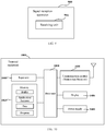
- FIG. 10 is a schematic diagram of a systematic structure of the terminal equipment of Embodiment 6 of this disclosure.
- a terminal equipment 1000 may include a processor 1010 and a memory 1020, the memory 1020 being coupled to the processor 1010.
- the memory 1020 being coupled to the processor 1010.
- his figure is illustrative only, and other types of structures may also be used, so as to supplement or replace this structure and achieve a telecommunications function or other functions.
- the functions of the signal transmission apparatus may be integrated into the processor 1010.
- the processor 1010 may be configured to, after a period of time of receiving a downlink signal related to beam failure recovery and before receiving or applying activation signaling or reconfiguration signaling, transmit an uplink signal in a first cell by using a spatial domain transmission filter identical to a spatial domain transmission filter transmitting an uplink signal related to beam failure recovery or receiving a downlink reference signal.
- the uplink signal in the first cell is transmitted by using the spatial domain transmission filter identical to the spatial domain transmission filter transmitting the uplink signal related to beam failure recovery.
- the uplink signal in the first cell is transmitted by using the spatial domain transmission filter identical to the spatial domain transmission filter receiving the downlink reference signal.
- the signal transmission apparatus and the processor 1010 may be configured separately; for example, the signal transmission apparatus may be configured as a chip connected to the processor 1010, and the functions of the signal transmission apparatus are executed under control of the processor 1010.
- the terminal equipment 1000 may further include a communication module 1030, an input unit 1040, a display 1050, and a power supply 1060. It should be noted that the terminal equipment 1000 does not necessarily include all the parts shown in FIG. 10 . Furthermore, the terminal equipment 1000 may include parts not shown in FIG. 10 , and the related art may be referred to.
- the processor 1010 is sometimes referred to as a controller or control, which may include a microprocessor or other processor devices and/or logic devices, and the processor 1010 receives input and controls operations of every component of the terminal equipment 1000.
- the memory 1020 may be, for example, one or more of a buffer memory, a flash memory, a hard drive, a mobile medium, a volatile memory, a nonvolatile memory, or other suitable devices, which may store the information on configuration, etc., and furthermore, store programs executing related information.
- the processor 1010 may execute programs stored in the memory 1020, so as to realize information storage or processing, etc. Functions of other parts are similar to those of the related art, which shall not be described herein any further.
- the parts of the terminal equipment 1000 may be realized by specific hardware, firmware, software, or any combination thereof, without departing from the scope of this disclosure.
- the terminal equipment transmits the uplink signal in the first cell by using the spatial domain transmission filter identical to a spatial domain transmission filter transmitting an uplink signal related to beam failure recovery or receiving a downlink reference signal.
- the solution has a wide range of applicability, and is not only suitable for scenarios where beam failure occurs in a special cell (SpCell), but also in scenarios where beam failure occurs in a secondary cell (SCell). Furthermore, this solution also accurately stipulates a starting point of the period of time, which avoids unnecessary errors in reception and transmission caused by inconsistent understanding of the period of time by the terminal equipment and the network device.
- the embodiment of this disclosure provides a network device, including the signal reception apparatus described in Embodiment 5.
- FIG. 11 is a schematic diagram of a structure of the network device of the embodiment of this disclosure.
- a network device 1100 may include a processor 1110 and a memory 1120, the memory 1120 being coupled to the processor 1110.
- the memory 1120 may store various data, and furthermore, it may store a program 1130 for information processing, and execute the program 1130 under control of the processor 1110, so as to receive various information transmitted by a terminal equipment and transmit various information to the terminal equipment.
- the functions of the signal reception apparatus may be integrated into the processor 1110.
- the processor 1110 may be configured to, after a period of time of transmitting a downlink signal related to beam failure recovery and before transmitting activation signaling or reconfiguration signaling or the activation signaling or reconfiguration signaling taking effect, receive an uplink signal in a first cell according to spatial information on receiving uplink signal related to beam failure recovery or transmitting a downlink reference signal.
- the uplink signal in the first cell is received according to spatial information on reception of the uplink signal related to beam failure recovery.
- the uplink signal in the first cell is received according to spatial information on transmission of the downlink reference signal.
- the signal reception apparatus and the processor 1110 may be configured separately; for example, the signal reception apparatus may be configured as a chip connected to the processor 1110, and the functions of the signal reception apparatus are executed under control of the processor 1110.
- the network device 1100 may include a transceiver 1140, and an antenna 1150, etc.
- functions of the above components are similar to those in the related art, and shall not be described herein any further.
- the network device 1100 does not necessarily include all the parts shown in FIG. 11 .
- the network device 1100 may include parts not shown in FIG. 11 , and the related art may be referred to.
- the network device receives the uplink signal in the first cell according to the spatial information on reception of the uplink signal related to beam failure recovery or transmission of a downlink reference signal.
- the solution has a wide range of applicability, and is not only suitable for scenarios where beam failure occurs in a special cell (SpCell), but also in scenarios where beam failure occurs in a secondary cell (SCell). Furthermore, this solution also accurately stipulates a starting point of the period of time, which avoids unnecessary errors in reception and transmission caused by inconsistent understanding of the period of time by the terminal equipment and the network device.
- the embodiment of this disclosure provides a communication system, including the terminal equipment described in Embodiment 6 and/or the network device described in Embodiment 7.
- the communication system 100 includes a network device 101 and a terminal equipment 102, the terminal equipment 102 being identical to the terminal equipment described in Embodiment 6, and the network device 101 being identical to the network device described in Embodiment 7, with repeated parts being not going to be described herein any further.
- the terminal equipment transmits the uplink signal in the first cell by using the spatial domain transmission filter identical to a spatial domain transmission filter transmitting an uplink signal related to beam failure recovery or receiving a downlink reference signal.
- the solution has a wide range of applicability, and is not only suitable for scenarios where beam failure occurs in a special cell (SpCell), but also in scenarios where beam failure occurs in a secondary cell (SCell). Furthermore, this solution also accurately stipulates a starting point of the period of time, which avoids unnecessary errors in reception and transmission caused by inconsistent understanding of the period of time by the terminal equipment and the network device.
- the above apparatuses and methods of this disclosure may be implemented by hardware, or by hardware in combination with software.
- This disclosure relates to such a computer-readable program that when the program is executed by a logic device, the logic device is enabled to carry out the apparatus or components as described above, or to carry out the methods or steps as described above.
- the present disclosure also relates to a storage medium for storing the above program, such as a hard disk, a floppy disk, a CD, a DVD, and a flash memory, etc.
- the methods/apparatuses described with reference to the embodiments of this disclosure may be directly embodied as hardware, software modules executed by a processor, or a combination thereof.
- one or more functional block diagrams and/or one or more combinations of the functional block diagrams shown in FIG. 8 may either correspond to software modules of procedures of a computer program, or correspond to hardware modules.
- Such software modules may respectively correspond to the steps shown in FIG. 2 .
- the hardware module for example, may be carried out by firming the soft modules by using a field programmable gate array (FPGA).
- FPGA field programmable gate array
- the soft modules may be located in an RAM, a flash memory, an ROM, an EPROM, and EEPROM, a register, a hard disc, a floppy disc, a CD-ROM, or any memory medium in other forms known in the art.
- a memory medium may be coupled to a processor, so that the processor may be able to read information from the memory medium, and write information into the memory medium; or the memory medium may be a component of the processor.
- the processor and the memory medium may be located in an ASIC.
- the soft modules may be stored in a memory of a mobile terminal, and may also be stored in a memory card of a pluggable mobile terminal.
- the soft modules may be stored in the MEGA-SIM card or the flash memory device of a large capacity.
- One or more functional blocks and/or one or more combinations of the functional blocks in FIG. 8 may be realized as a universal processor, a digital signal processor (DSP), an application-specific integrated circuit (ASIC), a field programmable gate array (FPGA) or other programmable logic devices, discrete gate or transistor logic devices, discrete hardware component or any appropriate combinations thereof carrying out the functions described in this application.
- DSP digital signal processor
- ASIC application-specific integrated circuit
- FPGA field programmable gate array
- the one or more functional block diagrams and/or one or more combinations of the functional block diagrams in FIG. 8 may also be realized as a combination of computing equipment, such as a combination of a DSP and a microprocessor, multiple processors, one or more microprocessors in communication combination with a DSP, or any other such configuration.
Applications Claiming Priority (1)
| Application Number | Priority Date | Filing Date | Title |
|---|---|---|---|
| PCT/CN2018/107718 WO2020061844A1 (fr) | 2018-09-26 | 2018-09-26 | Procédé d'envoi de signal, et procédé et dispositif de réception de signal |
Publications (3)
| Publication Number | Publication Date |
|---|---|
| EP3860295A1 true EP3860295A1 (fr) | 2021-08-04 |
| EP3860295A4 EP3860295A4 (fr) | 2021-11-10 |
| EP3860295B1 EP3860295B1 (fr) | 2023-11-22 |
Family
ID=69953183
Family Applications (1)
| Application Number | Title | Priority Date | Filing Date |
|---|---|---|---|
| EP18935975.5A Active EP3860295B1 (fr) | 2018-09-26 | 2018-09-26 | Procédé d'envoi de signal, et procédé et dispositif de réception de signal |
Country Status (6)
| Country | Link |
|---|---|
| US (2) | US11843437B2 (fr) |
| EP (1) | EP3860295B1 (fr) |
| JP (1) | JP7408633B2 (fr) |
| KR (1) | KR20210036385A (fr) |
| CN (1) | CN112640568B (fr) |
| WO (1) | WO2020061844A1 (fr) |
Families Citing this family (6)
| Publication number | Priority date | Publication date | Assignee | Title |
|---|---|---|---|---|
| JP2022503933A (ja) * | 2018-10-31 | 2022-01-12 | 富士通株式会社 | 信号送信方法、アンテナパネル情報の指示方法、装置及びシステム |
| WO2020191751A1 (fr) * | 2019-03-28 | 2020-10-01 | 富士通株式会社 | Procédé et appareil de rétablissement après défaillance de faisceau et système de communication |
| US20200314829A1 (en) * | 2019-03-29 | 2020-10-01 | Qualcomm Incorporated | Signaling-overhead reduction with resource grouping |
| CN113825232A (zh) * | 2020-06-19 | 2021-12-21 | 北京紫光展锐通信技术有限公司 | 资源更新方法及装置 |
| US11595105B1 (en) * | 2021-10-26 | 2023-02-28 | Qualcomm Incorporated | Beam failure recovery for a primary cell |
| AU2022433142A1 (en) * | 2022-01-13 | 2023-12-07 | Zte Corporation | System and method for determining a beam state of a downlink signal in a link recovery procedure |
Family Cites Families (13)
| Publication number | Priority date | Publication date | Assignee | Title |
|---|---|---|---|---|
| WO2017024516A1 (fr) | 2015-08-11 | 2017-02-16 | Telefonaktiebolaget Lm Ericsson (Publ) | Reprise après une défaillance de faisceau |
| WO2017197122A1 (fr) * | 2016-05-12 | 2017-11-16 | Sharp Laboratories Of America, Inc. | Procédé et appareil des sélection de ressources radio pour des communications de véhicule (v2x) en provenance d'un ensemble de ressources superposées |
| WO2018056789A1 (fr) * | 2016-09-26 | 2018-03-29 | 엘지전자(주) | Procédé de transmission/réception de liaison montante dans un système de communication sans fil, et dispositif associé |
| WO2018059399A1 (fr) * | 2016-09-30 | 2018-04-05 | 华为技术有限公司 | Procédé, dispositif, et système d'accès aléatoire, terminal, et station de base |
| WO2018136300A1 (fr) | 2017-01-17 | 2018-07-26 | Qualcomm Incorporated | Système et procédé de demande d'ajustement de faisceau |
| US11943677B2 (en) * | 2017-01-19 | 2024-03-26 | Qualcomm Incorporated | Beam selection and radio link failure during beam recovery |
| US10194442B2 (en) | 2017-02-10 | 2019-01-29 | Qualcomm Incorporated | Uplink resources for beam recovery |
| US11050478B2 (en) * | 2017-12-19 | 2021-06-29 | Samsung Electronics Co., Ltd. | Method and apparatus for beam reporting in next generation wireless systems |
| US11245458B2 (en) * | 2018-03-28 | 2022-02-08 | Beijing Xiaomi Mobile Software Co., Ltd. | Information transmission method and information transmission device |
| EP3864904A1 (fr) * | 2018-10-11 | 2021-08-18 | Lenovo (Singapore) Pte. Ltd. | Procédé et appareil pour déterminer des valeurs de paramètre de commande de puissance de canal de liaison montante physique pour une utilisation après rétablissement d'une défaillance de faisceau |
| EP4106257A1 (fr) * | 2019-01-09 | 2022-12-21 | Comcast Cable Communications LLC | Procédés, dispositifs et appareils de gestion de faisceau |
| CN111586862A (zh) * | 2019-02-15 | 2020-08-25 | 华为技术有限公司 | 信息指示的方法及装置 |
| US11398930B2 (en) * | 2019-05-02 | 2022-07-26 | Ofinno, Llc | Uplink operations of multi-transmission reception points and panel |
-
2018
- 2018-09-26 WO PCT/CN2018/107718 patent/WO2020061844A1/fr unknown
- 2018-09-26 EP EP18935975.5A patent/EP3860295B1/fr active Active
- 2018-09-26 JP JP2021510183A patent/JP7408633B2/ja active Active
- 2018-09-26 KR KR1020217005844A patent/KR20210036385A/ko not_active Application Discontinuation
- 2018-09-26 CN CN201880096972.1A patent/CN112640568B/zh active Active
-
2021
- 2021-02-24 US US17/183,723 patent/US11843437B2/en active Active
-
2023
- 2023-11-01 US US18/385,928 patent/US20240080081A1/en active Pending
Also Published As
| Publication number | Publication date |
|---|---|
| EP3860295A4 (fr) | 2021-11-10 |
| CN112640568A (zh) | 2021-04-09 |
| JP7408633B2 (ja) | 2024-01-05 |
| US11843437B2 (en) | 2023-12-12 |
| JP2021536176A (ja) | 2021-12-23 |
| CN112640568B (zh) | 2022-06-28 |
| WO2020061844A1 (fr) | 2020-04-02 |
| EP3860295B1 (fr) | 2023-11-22 |
| US20240080081A1 (en) | 2024-03-07 |
| US20210184749A1 (en) | 2021-06-17 |
| KR20210036385A (ko) | 2021-04-02 |
Similar Documents
| Publication | Publication Date | Title |
|---|---|---|
| US11843437B2 (en) | Signal transmission method, signal reception method and apparatuses thereof | |
| US11252629B2 (en) | Method and apparatus for recovering network connection and communication system | |
| US11064527B2 (en) | Random access method and apparatus and communication system | |
| US20210022128A1 (en) | Beam indication method, apparatus and system | |
| US20220053568A1 (en) | Random access method, apparatus, and storage medium | |
| US11310675B2 (en) | Uplink signal transmission method and apparatus, uplink signal reception method and apparatus and system | |
| WO2020029203A1 (fr) | Procédé, dispositif et support lisible par ordinateur pour reprise sur défaillance de faisceau pour cellule secondaire | |
| US11870732B2 (en) | Methods and nodes for activation or deactivation of a carrier in a communication network supporting carrier aggregation | |
| US20220053576A1 (en) | Random access method and device and communication system | |
| US20210168636A1 (en) | Method for assessing radio link quality, parameter configuration method, apparatuses thereof and system | |
| US20220006686A1 (en) | Beam failure recovery method and device and communication system | |
| US20210345397A1 (en) | Information transmission and reception methods and apparatuses thereof | |
| US20220256620A1 (en) | Random access method and apparatus and communication system | |
| US20220217785A1 (en) | Random access method and apparatus and communication system | |
| EP3911044A1 (fr) | Procédé et dispositif de transmission de données | |
| KR20220034839A (ko) | 랜덤 액세스 응답을 수신하기 위한 방법과 장치 및 2-단계 랜덤 액세스에서 랜덤 액세스 응답을 전송하기 위한 방법과 장치 | |
| US20220394781A1 (en) | Random access method and apparatus and communication system | |
| US20210219317A1 (en) | Signal transmission method, indication method for antenna panel information, apparatuses thereof and system | |
| EP3846572A1 (fr) | Procédé d'accès aléatoire, procédé de réception de données et dispositif associé, et système de communication | |
| US20240015665A1 (en) | Method and apparatus for transmitting uplink data and a system | |
| US20220217701A1 (en) | Wireless communication method and apparatus and communication system | |
| EP4231766A1 (fr) | Procédé, appareil et système de communication radio |
Legal Events
| Date | Code | Title | Description |
|---|---|---|---|
| STAA | Information on the status of an ep patent application or granted ep patent |
Free format text: STATUS: THE INTERNATIONAL PUBLICATION HAS BEEN MADE |
|
| PUAI | Public reference made under article 153(3) epc to a published international application that has entered the european phase |
Free format text: ORIGINAL CODE: 0009012 |
|
| STAA | Information on the status of an ep patent application or granted ep patent |
Free format text: STATUS: REQUEST FOR EXAMINATION WAS MADE |
|
| 17P | Request for examination filed |
Effective date: 20210212 |
|
| AK | Designated contracting states |
Kind code of ref document: A1 Designated state(s): AL AT BE BG CH CY CZ DE DK EE ES FI FR GB GR HR HU IE IS IT LI LT LU LV MC MK MT NL NO PL PT RO RS SE SI SK SM TR |
|
| A4 | Supplementary search report drawn up and despatched |
Effective date: 20211011 |
|
| RIC1 | Information provided on ipc code assigned before grant |
Ipc: H04W 72/04 20090101ALI20211005BHEP Ipc: H04W 74/08 20090101AFI20211005BHEP |
|
| DAV | Request for validation of the european patent (deleted) | ||
| DAX | Request for extension of the european patent (deleted) | ||
| GRAP | Despatch of communication of intention to grant a patent |
Free format text: ORIGINAL CODE: EPIDOSNIGR1 |
|
| STAA | Information on the status of an ep patent application or granted ep patent |
Free format text: STATUS: GRANT OF PATENT IS INTENDED |
|
| INTG | Intention to grant announced |
Effective date: 20230623 |
|
| RAP3 | Party data changed (applicant data changed or rights of an application transferred) |
Owner name: FUJITSU LIMITED |
|
| RIC1 | Information provided on ipc code assigned before grant |
Ipc: H04W 72/21 20230101ALI20230612BHEP Ipc: H04B 7/08 20060101ALI20230612BHEP Ipc: H04B 7/06 20060101ALI20230612BHEP Ipc: H04W 72/04 20090101ALI20230612BHEP Ipc: H04W 74/08 20090101AFI20230612BHEP |
|
| GRAS | Grant fee paid |
Free format text: ORIGINAL CODE: EPIDOSNIGR3 |
|
| GRAA | (expected) grant |
Free format text: ORIGINAL CODE: 0009210 |
|
| STAA | Information on the status of an ep patent application or granted ep patent |
Free format text: STATUS: THE PATENT HAS BEEN GRANTED |
|
| AK | Designated contracting states |
Kind code of ref document: B1 Designated state(s): AL AT BE BG CH CY CZ DE DK EE ES FI FR GB GR HR HU IE IS IT LI LT LU LV MC MK MT NL NO PL PT RO RS SE SI SK SM TR |
|
| REG | Reference to a national code |
Ref country code: GB Ref legal event code: FG4D |
|
| REG | Reference to a national code |
Ref country code: CH Ref legal event code: EP Ref country code: DE Ref legal event code: R096 Ref document number: 602018061678 Country of ref document: DE |
|
| REG | Reference to a national code |
Ref country code: IE Ref legal event code: FG4D |
|
| REG | Reference to a national code |
Ref country code: LT Ref legal event code: MG9D |
|
| REG | Reference to a national code |
Ref country code: NL Ref legal event code: MP Effective date: 20231122 |
|
| PG25 | Lapsed in a contracting state [announced via postgrant information from national office to epo] |
Ref country code: GR Free format text: LAPSE BECAUSE OF FAILURE TO SUBMIT A TRANSLATION OF THE DESCRIPTION OR TO PAY THE FEE WITHIN THE PRESCRIBED TIME-LIMIT Effective date: 20240223 |
|
| PG25 | Lapsed in a contracting state [announced via postgrant information from national office to epo] |
Ref country code: IS Free format text: LAPSE BECAUSE OF FAILURE TO SUBMIT A TRANSLATION OF THE DESCRIPTION OR TO PAY THE FEE WITHIN THE PRESCRIBED TIME-LIMIT Effective date: 20240322 |
|
| PG25 | Lapsed in a contracting state [announced via postgrant information from national office to epo] |
Ref country code: LT Free format text: LAPSE BECAUSE OF FAILURE TO SUBMIT A TRANSLATION OF THE DESCRIPTION OR TO PAY THE FEE WITHIN THE PRESCRIBED TIME-LIMIT Effective date: 20231122 |
|
| REG | Reference to a national code |
Ref country code: AT Ref legal event code: MK05 Ref document number: 1635055 Country of ref document: AT Kind code of ref document: T Effective date: 20231122 |
|
| PG25 | Lapsed in a contracting state [announced via postgrant information from national office to epo] |
Ref country code: NL Free format text: LAPSE BECAUSE OF FAILURE TO SUBMIT A TRANSLATION OF THE DESCRIPTION OR TO PAY THE FEE WITHIN THE PRESCRIBED TIME-LIMIT Effective date: 20231122 |
|
| PG25 | Lapsed in a contracting state [announced via postgrant information from national office to epo] |
Ref country code: AT Free format text: LAPSE BECAUSE OF FAILURE TO SUBMIT A TRANSLATION OF THE DESCRIPTION OR TO PAY THE FEE WITHIN THE PRESCRIBED TIME-LIMIT Effective date: 20231122 |
|
| PG25 | Lapsed in a contracting state [announced via postgrant information from national office to epo] |
Ref country code: ES Free format text: LAPSE BECAUSE OF FAILURE TO SUBMIT A TRANSLATION OF THE DESCRIPTION OR TO PAY THE FEE WITHIN THE PRESCRIBED TIME-LIMIT Effective date: 20231122 |
|
| PG25 | Lapsed in a contracting state [announced via postgrant information from national office to epo] |
Ref country code: NL Free format text: LAPSE BECAUSE OF FAILURE TO SUBMIT A TRANSLATION OF THE DESCRIPTION OR TO PAY THE FEE WITHIN THE PRESCRIBED TIME-LIMIT Effective date: 20231122 Ref country code: LT Free format text: LAPSE BECAUSE OF FAILURE TO SUBMIT A TRANSLATION OF THE DESCRIPTION OR TO PAY THE FEE WITHIN THE PRESCRIBED TIME-LIMIT Effective date: 20231122 Ref country code: IS Free format text: LAPSE BECAUSE OF FAILURE TO SUBMIT A TRANSLATION OF THE DESCRIPTION OR TO PAY THE FEE WITHIN THE PRESCRIBED TIME-LIMIT Effective date: 20240322 Ref country code: GR Free format text: LAPSE BECAUSE OF FAILURE TO SUBMIT A TRANSLATION OF THE DESCRIPTION OR TO PAY THE FEE WITHIN THE PRESCRIBED TIME-LIMIT Effective date: 20240223 Ref country code: ES Free format text: LAPSE BECAUSE OF FAILURE TO SUBMIT A TRANSLATION OF THE DESCRIPTION OR TO PAY THE FEE WITHIN THE PRESCRIBED TIME-LIMIT Effective date: 20231122 Ref country code: BG Free format text: LAPSE BECAUSE OF FAILURE TO SUBMIT A TRANSLATION OF THE DESCRIPTION OR TO PAY THE FEE WITHIN THE PRESCRIBED TIME-LIMIT Effective date: 20240222 Ref country code: AT Free format text: LAPSE BECAUSE OF FAILURE TO SUBMIT A TRANSLATION OF THE DESCRIPTION OR TO PAY THE FEE WITHIN THE PRESCRIBED TIME-LIMIT Effective date: 20231122 Ref country code: PT Free format text: LAPSE BECAUSE OF FAILURE TO SUBMIT A TRANSLATION OF THE DESCRIPTION OR TO PAY THE FEE WITHIN THE PRESCRIBED TIME-LIMIT Effective date: 20240322 |