EP3860200A1 - Data transmission method and device - Google Patents
Data transmission method and device Download PDFInfo
- Publication number
- EP3860200A1 EP3860200A1 EP19866919.4A EP19866919A EP3860200A1 EP 3860200 A1 EP3860200 A1 EP 3860200A1 EP 19866919 A EP19866919 A EP 19866919A EP 3860200 A1 EP3860200 A1 EP 3860200A1
- Authority
- EP
- European Patent Office
- Prior art keywords
- measurement value
- side layer
- tce
- layer
- acquiring
- Prior art date
- Legal status (The legal status is an assumption and is not a legal conclusion. Google has not performed a legal analysis and makes no representation as to the accuracy of the status listed.)
- Pending
Links
Images


Classifications
-
- H—ELECTRICITY
- H04—ELECTRIC COMMUNICATION TECHNIQUE
- H04W—WIRELESS COMMUNICATION NETWORKS
- H04W24/00—Supervisory, monitoring or testing arrangements
- H04W24/10—Scheduling measurement reports ; Arrangements for measurement reports
-
- H—ELECTRICITY
- H04—ELECTRIC COMMUNICATION TECHNIQUE
- H04W—WIRELESS COMMUNICATION NETWORKS
- H04W24/00—Supervisory, monitoring or testing arrangements
- H04W24/08—Testing, supervising or monitoring using real traffic
-
- H—ELECTRICITY
- H04—ELECTRIC COMMUNICATION TECHNIQUE
- H04W—WIRELESS COMMUNICATION NETWORKS
- H04W80/00—Wireless network protocols or protocol adaptations to wireless operation
- H04W80/02—Data link layer protocols
-
- H—ELECTRICITY
- H04—ELECTRIC COMMUNICATION TECHNIQUE
- H04W—WIRELESS COMMUNICATION NETWORKS
- H04W88/00—Devices specially adapted for wireless communication networks, e.g. terminals, base stations or access point devices
- H04W88/08—Access point devices
- H04W88/085—Access point devices with remote components
-
- H—ELECTRICITY
- H04—ELECTRIC COMMUNICATION TECHNIQUE
- H04W—WIRELESS COMMUNICATION NETWORKS
- H04W24/00—Supervisory, monitoring or testing arrangements
- H04W24/02—Arrangements for optimising operational condition
-
- H—ELECTRICITY
- H04—ELECTRIC COMMUNICATION TECHNIQUE
- H04W—WIRELESS COMMUNICATION NETWORKS
- H04W92/00—Interfaces specially adapted for wireless communication networks
- H04W92/04—Interfaces between hierarchically different network devices
- H04W92/12—Interfaces between hierarchically different network devices between access points and access point controllers
Definitions
- the present application relates to, but is not limited to, the field of communications, for example, relates to, but is not limited to, a data transmission method and apparatus.
- drive test can reflect the status of a mobile communication network, directly measure and evaluate network performance indicators, and point out problems of the network.
- the drive test is an important means for network optimization.
- an operator or a third-party company is required to test an area to be monitored and optimized, specifically, collect network data such as signal level and quality by means of drive test instruments, and analyze the data, so as to discover problems of the network. This method usually requires a lot of manpower, material resources and financial investment, and also imposes very high experience requirements on network optimization personnel.
- a minimization of drive tests (MDT) technology is mainly to acquire relevant parameters such as a layer 2 measurement value required for network optimization through a measurement report reported by a terminal device, so as to reach the goal of reducing the network optimization and maintenance costs of the operator.
- MDT can save energy and reduce emissions, reduce drive test costs, shorten an optimization cycle, and bring higher user satisfaction.
- the MDT can collect measurement information of a whole area (such as narrow roads, forests, and private places) that cannot be obtained through the traditional drive tests.
- the MDT include following functions: automatically collecting measurement information such as the layer 2 measurement value by means of a user equipment (UE); reporting the measurement information to a radio access network (RAN) via control plane signaling, where the RAN may correspond to an evolved NodeB (eNB) in an Evolved UMTS Terrestrial Radio Access Network (E-UTRAN) and a next generation NodeB (gNB) in an NR system; and reporting the measurement information to a trace collection entity (TCE) through the RAN.
- eNB evolved NodeB
- E-UTRAN Evolved UMTS Terrestrial Radio Access Network
- gNB next generation NodeB
- TCE trace collection entity
- the MDT may be classified into following modes: logged MDT and immediate MDT.
- the UE performs recording and measurement in a Radio Resource Control (RRC) idle state.
- RRC Radio Resource Control
- the UE performs measurement and reporting in an RRC connected state.
- the MDT configuration information required for the UE to perform the MDT includes an area scope, trace reference, a measurement type to be performed by the UE, an IP address of the TCE, etc.
- a base station may be divided into two parts: a central unit (CU) and a distributed unit (DU).
- One base station includes one CU and may include multiple DUs, which is referred to as CU/DU split.
- An interface between the CU and the DU is referred to as an F1 interface.
- the CU may be divided into a CU control plane (CU-CP) and a CU user plane (CU-UP).
- CU-CP CU control plane
- CU-UP CU user plane
- One CU includes one CP and may include multiple UPs, which is referred to as CP/UP split.
- An interface between the CP and the UP is referred to as an E1 interface.
- the terminal device cannot report the layer 2 measurement value.
- the embodiments of the present application provide a data transmission method and apparatus.
- a data transmission method includes steps described below.
- a communication node acquires a layer 2 measurement value.
- the communication node sends the layer 2 measurement value to a trace collection entity (TCE).
- TCE trace collection entity
- a data transmission method is further provided and includes steps described below.
- a distributed unit (DU) acquires a DU-side layer 2 measurement value.
- the DU sends the DU-side layer 2 measurement value to a central unit (CU) or directly to a trace collection entity (TCE).
- CU central unit
- TCE trace collection entity
- a data transmission method includes steps described below.
- a central unit (CU) acquires a DU-side layer 2 measurement value transmitted by a distributed unit (DU).
- the CU transmits the DU-side layer 2 measurement value and a CU-side layer 2 measurement value to a trace collection entity (TCE).
- TCE trace collection entity
- a data transmission method includes steps described below.
- a central unit user plane acquires a CU-UP-side layer 2 measurement value.
- the CU-UP sends the CU-UP-side layer 2 measurement value to a central unit control plane (CU-CP) or directly to a trace collection entity (TCE).
- CU-CP central unit control plane
- TCE trace collection entity
- a data transmission method includes steps described below.
- a central unit control plane (CU-CP) acquires a CU-UP-side layer 2 measurement value transmitted by a CU-UP.
- the CU-CP transmits the CU-UP-side layer 2 measurement value to a trace collection entity (TCE).
- TCE trace collection entity
- a data transmission apparatus applied to a communication node, includes a first acquisition module and a first sending module.
- the first acquisition module is configured to acquire a layer 2 measurement value.
- the first sending module is configured to send the layer 2 measurement value to a trace collection entity (TCE).
- TCE trace collection entity
- a data transmission apparatus applied to a distributed unit (DU), includes a second acquisition module and a second sending module.
- the second acquisition module is configured to acquire a DU-side layer 2 measurement value.
- the second sending module is configured to send the DU-side layer 2 measurement value to a central unit (CU) or directly to a trace collection entity (TCE).
- CU central unit
- TCE trace collection entity
- a data transmission apparatus applied to a central unit, includes a third acquisition module and a third sending module.
- the third acquisition module is configured to acquire a DU-side layer 2 measurement value transmitted by a distributed unit (DU).
- the third sending module is configured to transmit the DU-side layer 2 measurement value and a CU-side layer 2 measurement value to a trace collection entity (TCE).
- TCE trace collection entity
- a data transmission apparatus applied to a central unit user plane (CU-UP), includes a fourth acquisition module and a fourth sending module.
- the fourth acquisition module is configured to acquire a CU-UP-side layer 2 measurement value.
- the fourth sending module is configured to send the CU-UP-side layer 2 measurement value to a central unit control plane (CU-CP) or directly to a trace collection entity (TCE).
- CU-CP central unit control plane
- TCE trace collection entity
- a data transmission apparatus applied to a central unit control plane (CU-CP), includes a fifth acquisition module and a fifth sending module.
- the fifth acquisition module is configured to acquire a CU-UP-side layer 2 measurement value transmitted by a central unit user plane (CU-UP).
- the fifth sending module is configured to transmit the CU-UP-side layer 2 measurement value to a trace collection entity (TCE).
- TCE trace collection entity
- An embodiment of the present application further provides a storage medium.
- the storage medium stores a computer program, where any one of the data transmission methods described above is performed when the computer program is executed.
- an electronic apparatus includes a memory and a processor, where the memory stores a computer program, and the processor is configured to execute the computer program to perform any one of the data transmission methods described above.
- the embodiments of the present application provide a mobile communication network (which includes, but is not limited to, a 5G mobile communication network).
- the network architecture of the mobile communication network may include a network-side device (such as a base station) and a terminal (including a mobile terminal).
- the embodiments of the present application provide at least a data transmission method executable on the preceding network architecture.
- the communication node 10 may include one or more (only one is shown in FIG. 1 ) processors 102 (the processor 102 may include, but are not limited to, a microcontroller unit (MCU), a field programmable gate array (FPGA) and other processing apparatuses) and a memory 104 configured to store data.
- the preceding communication node may further include a transmission apparatus 106 for a communication function and an input/output device 108. It is understandable by those skilled in the art that the structure shown in FIG.
- the communication node 10 may further include more or fewer components than the components shown in FIG. 1 or has a configuration different from the configuration shown in FIG. 1 .
- the memory 104 may be configured to store software programs and modules of application software, such as program instructions/modules corresponding to the data transmission method in the embodiments of the present application.
- the processor 102 executes the software programs and modules stored in the memory 104 to perform various functional applications and data processing, that is, to implement the data transmission method described above.
- the memory 104 may include a high-speed random-access memory and may further include a nonvolatile memory such as one or more magnetic storage apparatuses, flash memories, or other nonvolatile solid-state memories.
- the memory 104 may include memories which are remotely disposed with respect to the processor 102 and these remote memories may be connected to the communication node 10 via a network.
- the examples of the preceding network include, but are not limited to, the Internet, an intranet, a local area network, a mobile communication network, and a combination thereof.
- the transmission apparatus 106 is configured to receive or send data via a network.
- An example of the preceding network may include a wireless network provided by a communication provider of the communication node 10.
- the transmission apparatus 106 includes a network interface controller (NIC) which may be connected to another network device via a base station and thus communicate with the Internet.
- the transmission apparatus 106 may be a radio frequency (RF) module configured to wirelessly communicate with the Internet.
- NIC network interface controller
- RF radio frequency
- FIG. 2 is a flowchart of a data transmission method according to an embodiment of the present application. As shown in FIG. 2 , the method includes steps described below.
- step S202 a communication node acquires a layer 2 measurement value.
- the preceding communication node may be a base station.
- Layer 2 refers to layer 2 in a communication system and includes a Packet Data Convergence Protocol (PDCP), a radio link control (RLC) protocol, and a media access control (MAC) protocol.
- PDCP Packet Data Convergence Protocol
- RLC radio link control
- MAC media access control
- the layer 2 measurement value is a measurement value to be processed in layer 2 and may include the following parameters of layer 2: uplink and downlink packet loss rates, an interface delay, an air interface delay, uplink and downlink physical resource block (PRB) usage, the number of Radio Resource Control (RRC) connections, and uplink and downlink UE throughput.
- PRB physical resource block
- RRC Radio Resource Control
- step S204 the communication node sends the layer 2 measurement value to a trace collection entity (TCE).
- TCE trace collection entity
- the communication node acquires the layer 2 measurement value and reports the layer 2 measurement value to the TCE, which solves the problem in the related art of a lack of a layer 2 measurement data reporting solution applicable to New Radio and provides a method for reporting the layer 2 measurement value applicable to New Radio.
- the preceding steps may be executed by the base station or the like.
- the step in which the communication node acquires the layer 2 measurement value includes at least one of steps described below.
- a central unit (CU) of the communication node acquires a DU-side layer 2 measurement value reported by a distributed unit (DU).
- a CU control plane (CU-CP) of the communication node acquires a CU-UP-side layer 2 measurement value reported by a CU user plane (CU-UP).
- the method further includes at least one of steps described below.
- the CU of the communication node receives, through an F1 interface, the DU-side layer 2 measurement value reported by the DU.
- the CU-CP of the communication node receives, through an E1 interface, the CU-UP-side layer 2 measurement value reported by the CU-UP.
- the step in which the communication node sends the layer 2 measurement value to the trace collection entity (TCE) includes one of steps described below.
- the CU of the communication node acquires the DU-side layer 2 measurement value reported by the DU, and after acquiring the DU-side layer 2 measurement value, reports the DU-side layer 2 measurement value and a CU-side layer 2 measurement value to the TCE.
- the CU of the communication node reports the CU-side layer 2 measurement value to the TCE, and the DU of the communication node directly reports the DU-side layer 2 measurement value to the TCE.
- the method before the DU of the communication node reports the DU-side layer 2 measurement value to the TCE, the method further includes at least one of steps described below.
- the DU acquires an IP address of the TCE from the CU via F1 interface signaling.
- the DU acquires the IP address of the TCE from OAM
- the step in which the communication node sends the layer 2 measurement value to the trace collection entity (TCE) includes one of steps described below.
- the CU-CP of the communication node acquires the CU-UP-side layer 2 measurement value, and after acquiring the CU-UP-side layer 2 measurement value, reports the acquired CU-UP-side layer 2 measurement value to the TCE.
- the CU-UP of the communication node directly reports the CU-UP-side layer 2 measurement value to the TCE.
- the CU-UP before the CU-UP of the communication node reports the CU-UP-side layer 2 measurement value to the TCE, the CU-UP acquires the IP address of the TCE from the CU-CP via E1 interface signaling; or the CU-UP acquires the IP address of the TCE from the OAM
- the layer 2 measurement value includes at least one of: the uplink and downlink packet loss rates, the interface delay, the air interface delay, the uplink and downlink PRB usage, the number of RRC connections, or the uplink and downlink UE throughput.
- the communication node before the communication node sends the layer 2 measurement value to the trace collection entity (TCE), the communication node acquires the IP address of the TCE from the OAM
- a data transmission method is further provided and includes steps described below.
- a distributed unit acquires a DU-side layer 2 measurement value.
- step two the DU sends the DU-side layer 2 measurement value to a central unit (CU) or directly to a trace collection entity (TCE).
- CU central unit
- TCE trace collection entity
- the distributed unit (DU) of a communication node acquires the DU-side layer 2 measurement value and reports the DU-side layer 2 measurement value to the central unit (CU) or the TCE, which solves the problem in the related art of a lack of a layer 2 measurement data reporting solution applicable to New Radio and provides a method for reporting the layer 2 measurement value applicable to New Radio.
- the CU when the DU sends the DU-side layer 2 measurement value to the TCE, the CU also reports a CU-side layer 2 measurement value to the TCE.
- the step in which the DU sends the DU-side layer 2 measurement value to the CU includes that the DU sends the DU-side layer 2 measurement value to the CU through an F1 interface.
- the method before the DU sends the DU-side layer 2 measurement value to the TCE, the method includes one of the following steps: the DU acquires an IP address of the TCE from the CU, or the DU acquires the IP address of the TCE from OAM
- a data transmission method is further provided and includes steps described below.
- a central unit acquires a DU-side layer 2 measurement value transmitted by a distributed unit (DU).
- step two the CU transmits the DU-side layer 2 measurement value and a CU-side layer 2 measurement value to a trace collection entity (TCE).
- TCE trace collection entity
- the CU of a communication node acquires the DU-side layer 2 measurement value transmitted by the DU and reports the DU-side layer 2 measurement value and the CU-side layer 2 measurement value together to the TCE, which solves the problem in the related art of a lack of a layer 2 measurement data reporting solution applicable to New Radio and provides a method for reporting the layer 2 measurement value applicable to New Radio.
- a data transmission method is further provided and includes steps described below.
- a central unit user plane acquires a CU-UP-side layer 2 measurement value.
- step two the CU-UP sends the CU-UP-side layer 2 measurement value to a central unit control plane (CU-CP) or directly a trace collection entity (TCE).
- CU-CP central unit control plane
- TCE trace collection entity
- the user plane acquires its own CU-UP-side layer 2 measurement value and sends the CU-UP-side layer 2 measurement value to the control plane (CP) or directly to the TCE, which solves the problem in the related art of a lack of a layer 2 measurement data reporting solution applicable to New Radio and provides a method for reporting the layer 2 measurement value applicable to New Radio.
- CP control plane
- the preceding solution is used for describing a solution in the case of CP/UP split of the central unit, and the relationship of CU/DU split is not limited here.
- the CP/UP split and the CU/DU split may exist at the same time.
- the step in which the CU-UP sends the CU-UP-side layer 2 measurement value to the CU-CP includes that the CU-UP sends the CU-UP-side layer 2 measurement value to the CU-CP through an E1 interface.
- the method before the CU-UP sends the CU-UP-side layer 2 measurement value to the TCE, the method further includes one of steps described below.
- the CU-UP acquires an IP address of the TCE from the CU-CP.
- the CU-UP acquires the IP address of the TCE from OAM
- a data transmission method is further provided and includes steps described below.
- a central unit control plane acquires a CU-UP-side layer 2 measurement value transmitted by a central unit user plane (CU-UP).
- step two the CU-CP transmits the CU-UP-side layer 2 measurement value to a trace collection entity (TCE).
- TCE trace collection entity
- the control plane acquires the CU-UP-side layer 2 measurement value from the user plane and sends the CU-UP-side layer 2 measurement value to the TCE, which solves the problem in the related art of a lack of a layer 2 measurement data reporting solution applicable to New Radio and provides a method for reporting the layer 2 measurement value applicable to New Radio.
- FIG. 3 is a schematic diagram illustrating that a gNB-CU uniformly reports layer 2 measurement reports according to embodiment 1 of the present application. As shown in FIG. 3 , the process includes steps described below.
- a gNB-DU reports layer 2 measurement data collected by the gNB-DU to a gNB-CU through a measurement report.
- step 2 the gNB-CU integrates layer 2 measurement data collected by the gNB-CU and the layer 2 measurement data reported by the gNB-DU, and reports the integrated layer 2 measurement data to a TCE through a measurement report.
- FIG. 4 is a schematic diagram illustrating that a CU and a DU separately report layer 2 measurement reports according to embodiment 2 of the present application. As shown in FIG. 4 , the process includes steps described below.
- a gNB-CU sends an MDT configuration including an IP address of a TCE to a gNB-DU through a UE context setup request message or a UE context modification request message.
- step 2 after receiving the IP address of the TCE, the gNB-DU directly reports layer 2 measurement data collected at the gNB-DU side to the TCE through a layer 2 measurement report.
- step 3 the gNB-CU reports layer 2 measurement data collected at the gNB-CU side to the TCE through a layer 2 measurement report.
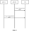
- FIG. 5 is a schematic diagram illustrating that a gNB-CU and a gNB-DU separately report layer 2 measurement reports after the gNB-DU acquires an IP address of a TCE from OAM according to embodiment 3 of the present application. As shown in FIG. 5 , the process includes steps described below.
- step 1 after the gNB-DU acquires the IP address of the TCE from the OAM, the gNB-DU may directly report layer 2 measurement data collected at the gNB-DU side to the TCE through a layer 2 measurement report.
- step 2 the gNB-CU reports layer 2 measurement data collected at the gNB-CU side to the TCE through a layer 2 measurement report.
- FIG. 6 is a schematic diagram illustrating that a gNB-CU-CP reports a layer 2 measurement report according to embodiment 4 of the present application. As shown in FIG. 6 , the process includes steps described below.
- a gNB-CU-UP reports layer 2 measurement data collected by the gNB-CU-UP to the gNB-CU-CP through a measurement report.
- step 2 the gNB-CU-CP reports the obtained layer 2 measurement data to a TCE through the measurement report.
- FIG. 7 is a schematic diagram illustrating that a gNB-CU-UP directly reports a layer 2 measurement report after the gNB-CU-UP acquires an MDT configuration from a gNB-CU-CP according to embodiment 5 of the present application. As shown in FIG. 7 , the process includes steps described below.
- step 1 the gNB-CU-CP sends the MDT configuration including an IP address of a TCE to the gNB-CU-UP through a bearer context setup request message or a bearer context modification request message.
- step 2 after receiving the IP address of the TCE, the gNB-CU-UP directly reports layer 2 measurement data collected at the gNB-CU-UP side to the TCE through the layer 2 measurement report.
- FIG. 8 is a schematic diagram illustrating that a gNB-CU-UP directly reports a layer 2 measurement report after the gNB-CU-UP acquires an IP address of a TCE from OAM according to embodiment 6 of the present application. As shown in FIG. 8 , the process includes a step described below.
- step 1 after the gNB-CU-UP acquires the IP address of the TCE from the OAM, the gNB-CU-UP may directly report layer 2 measurement data collected at the gNB-CU-UP side to the TCE through the layer 2 measurement report.
- the method for transmitting and reporting layer 2 measurement data provided by the present application, in the case of CU/DU split and CP/UP split, can specify a manner for transmitting and reporting the layer 2 measurement data between different entities and fill a gap in the related field.
- the methods in the embodiments described above may be implemented by software plus a necessary general-purpose hardware platform, or may of course be implemented by hardware. However, in many cases, the former is a preferred implementation.
- the solutions of the present application substantially, or the part contributing to the existing art, may be embodied in the form of a software product.
- the computer software product is stored on a storage medium (such as a ROM/RAM, a magnetic disk, or an optical disk) and includes one or more instructions to enable a terminal device (which may be a mobile phone, a computer, a server, or a network device) to perform the method according to any one of the embodiments of the present application.
- module may be software, hardware, or a combination thereof capable of implementing predetermined functions.
- Another embodiment of the present application further provides a data transmission apparatus applied to a communication node and including an acquisition module and a sending module.
- the acquisition module may be a first acquisition module
- the sending module may be a first sending module.
- the first acquisition module is configured to acquire a layer 2 measurement value.
- the first sending module is configured to send the layer 2 measurement value to a trace collection entity (TCE).
- TCE trace collection entity
- the communication node acquires the layer 2 measurement value and reports the layer 2 measurement value to the TCE, which solves the problem in the related art of a lack of a layer 2 measurement data reporting solution applicable to New Radio and provides a method for reporting the layer 2 measurement value applicable to New Radio.
- Another embodiment of the present application further provides a data transmission apparatus applied to a distributed unit (DU) and including an acquisition module and a sending module.
- the acquisition module may be a second acquisition module
- the sending module may be a second sending module.
- the second acquisition module is configured to acquire a DU-side layer 2 measurement value.
- the second sending module is configured to send the DU-side layer 2 measurement value to a central unit (CU) or directly to a trace collection entity (TCE).
- CU central unit
- TCE trace collection entity
- the distributed unit (DU) of a communication node acquires the DU-side layer 2 measurement value and reports the DU-side layer 2 measurement value to the central unit (CU) or the TCE, which solves the problem in the related art of a lack of a layer 2 measurement data reporting solution applicable to New Radio and provides a method for reporting the layer 2 measurement value applicable to New Radio.
- Another embodiment of the present application further provides a data transmission apparatus applied to a central unit and including an acquisition module and a sending module.
- the acquisition module may be a third acquisition module
- the sending module may be a third sending module.
- the third acquisition module is configured to acquire a DU-side layer 2 measurement value transmitted by a distributed unit (DU).
- DU distributed unit
- the third sending module is configured to transmit the DU-side layer 2 measurement value and a CU-side layer 2 measurement value to a trace collection entity (TCE).
- TCE trace collection entity
- the CU of a communication node acquires the DU-side layer 2 measurement value transmitted by the DU and reports the DU-side layer 2 measurement value and the CU-side layer 2 measurement value together to the TCE, which solves the problem in the related art of a lack of a layer 2 measurement data reporting solution applicable to New Radio and provides a method for reporting the layer 2 measurement value applicable to New Radio.
- Another embodiment of the present application further provides a data transmission apparatus applied to a central unit user plane (CU-UP) and including an acquisition module and a sending module.
- the acquisition module may be a fourth acquisition module
- the sending module may be a fourth sending module.
- the fourth acquisition module is configured to acquire a CU-UP-side layer 2 measurement value.
- the fourth sending module is configured to send the CU-UP-side layer 2 measurement value to a central unit control plane (CU-CP) or directly to a trace collection entity (TCE).
- CU-CP central unit control plane
- TCE trace collection entity
- the user plane acquires its CU-UP-side layer 2 measurement value and sends the CU-UP-side layer 2 measurement value to the control plane (CP) or directly sends the CU-UP-side layer 2 measurement value to the TCE, which solves the problem in the related art of a lack of a layer 2 measurement data reporting solution applicable to New Radio and provides a method for reporting the layer 2 measurement value applicable to New Radio.
- Another embodiment of the present application further provides a data transmission apparatus applied to a central unit control plane (CU-CP) and including an acquisition module and a sending module.
- the acquisition module may be a fifth acquisition module
- the sending module may be a fifth sending module.
- the fifth acquisition module is configured to acquire a CU-UP-side layer 2 measurement value transmitted by a central unit user plane (CU-UP).
- CU-UP central unit user plane
- the fifth sending module is configured to send the CU-UP-side layer 2 measurement value to a trace collection entity (TCE).
- TCE trace collection entity
- the control plane acquires the CU-UP-side layer 2 measurement value from the user plane and sends the CU-UP-side layer 2 measurement value and a CU-CP-side layer 2 measurement value together to the TCE, which solves the problem in the related art of a lack of a layer 2 measurement data reporting solution applicable to New Radio and provides a method for reporting the layer 2 measurement value applicable to New Radio.
- each module described above may be implemented by software or hardware. Implementation by hardware may, but may not necessarily, be performed in the following manners: the modules described above are located in a same processor, or each module described above is located in a respective processor in any combination form.
- An embodiment of the present application further provides a storage medium.
- the storage medium may be configured to store program codes for executing any one of the data transmission methods described above.
- program codes stored in the storage medium when executed, may implement steps described below.
- a communication node acquires a layer 2 measurement value.
- the communication node sends the layer 2 measurement value to a trace collection entity (TCE).
- TCE trace collection entity
- the storage medium may include, but is not limited to, a USB flash disk, a read-only memory (ROM), a random access memory (RAM), a mobile hard disk, a magnetic disk, an optical disk, or other media capable of storing program codes.
- An embodiment of the present application further provides an electronic apparatus including a memory and a processor, where the memory stores a computer program, and the processor is configured to execute the computer program to perform any one of the data transmission methods described above.
- the electronic apparatus may further include a transmission apparatus and an input/output device.
- the transmission apparatus is connected to the processor.
- the input/output device is connected to the processor.
- the processor may be configured to perform steps described below through the computer program.
- a communication node acquires a layer 2 measurement value.
- the communication node sends the layer 2 measurement value to a trace collection entity (TCE).
- TCE trace collection entity
- each of the above-mentioned modules or steps of the present application may be implemented by a general-purpose computing apparatus, the modules or steps may be concentrated on a single computing apparatus or distributed on a network composed of multiple computing apparatuses, and the modules or steps may be implemented by program codes executable by the computing apparatus, so that the modules or steps may be stored in a storage apparatus and executed by the computing apparatus.
- the illustrated or described steps may be executed in sequences different from those described herein, or the modules or steps may be made into various integrated circuit modules separately, or multiple modules or steps therein may be made into a single integrated circuit module for implementation. In this way, the present application is not limited to any particular combination of hardware and software.
Abstract
Description
- This application claims priority to Chinese Patent Application No.
201811141908.9 - The present application relates to, but is not limited to, the field of communications, for example, relates to, but is not limited to, a data transmission method and apparatus.
- In communication technologies, drive test can reflect the status of a mobile communication network, directly measure and evaluate network performance indicators, and point out problems of the network. For operators, the drive test is an important means for network optimization. In a traditional drive testing method, an operator or a third-party company is required to test an area to be monitored and optimized, specifically, collect network data such as signal level and quality by means of drive test instruments, and analyze the data, so as to discover problems of the network. This method usually requires a lot of manpower, material resources and financial investment, and also imposes very high experience requirements on network optimization personnel.
- A minimization of drive tests (MDT) technology is mainly to acquire relevant parameters such as a
layer 2 measurement value required for network optimization through a measurement report reported by a terminal device, so as to reach the goal of reducing the network optimization and maintenance costs of the operator. Compared with traditional drive tests, MDT can save energy and reduce emissions, reduce drive test costs, shorten an optimization cycle, and bring higher user satisfaction. Moreover, the MDT can collect measurement information of a whole area (such as narrow roads, forests, and private places) that cannot be obtained through the traditional drive tests. - The MDT include following functions: automatically collecting measurement information such as the
layer 2 measurement value by means of a user equipment (UE); reporting the measurement information to a radio access network (RAN) via control plane signaling, where the RAN may correspond to an evolved NodeB (eNB) in an Evolved UMTS Terrestrial Radio Access Network (E-UTRAN) and a next generation NodeB (gNB) in an NR system; and reporting the measurement information to a trace collection entity (TCE) through the RAN. The MDT is used for network optimization, for example, finding and solving a network coverage problem. - According to the state where the UE is when performing the MDT, the MDT may be classified into following modes: logged MDT and immediate MDT. In the logged MDT mode, the UE performs recording and measurement in a Radio Resource Control (RRC) idle state. In the immediate MDT mode, the UE performs measurement and reporting in an RRC connected state. The MDT configuration information required for the UE to perform the MDT includes an area scope, trace reference, a measurement type to be performed by the UE, an IP address of the TCE, etc.
- In the fifth generation of mobile communications (5G), a base station may be divided into two parts: a central unit (CU) and a distributed unit (DU). One base station includes one CU and may include multiple DUs, which is referred to as CU/DU split. An interface between the CU and the DU is referred to as an F1 interface. The CU may be divided into a CU control plane (CU-CP) and a CU user plane (CU-UP). One CU includes one CP and may include multiple UPs, which is referred to as CP/UP split. An interface between the CP and the UP is referred to as an E1 interface. In New Radio scenarios such as 5G in the related art, the terminal device cannot report the
layer 2 measurement value. - The embodiments of the present application provide a data transmission method and apparatus.
- According to an embodiment of the present application, a data transmission method includes steps described below. A communication node acquires a
layer 2 measurement value. The communication node sends thelayer 2 measurement value to a trace collection entity (TCE). - According to another embodiment of the present application, a data transmission method is further provided and includes steps described below. A distributed unit (DU) acquires a DU-
side layer 2 measurement value. The DU sends the DU-side layer 2 measurement value to a central unit (CU) or directly to a trace collection entity (TCE). - According to another embodiment of the present application, a data transmission method includes steps described below. A central unit (CU) acquires a DU-
side layer 2 measurement value transmitted by a distributed unit (DU). The CU transmits the DU-side layer 2 measurement value and a CU-side layer 2 measurement value to a trace collection entity (TCE). - According to yet another embodiment of the present application, a data transmission method includes steps described below. A central unit user plane (CU-UP) acquires a CU-UP-
side layer 2 measurement value. The CU-UP sends the CU-UP-side layer 2 measurement value to a central unit control plane (CU-CP) or directly to a trace collection entity (TCE). - According to still another embodiment of the present application, a data transmission method includes steps described below. A central unit control plane (CU-CP) acquires a CU-UP-
side layer 2 measurement value transmitted by a CU-UP. The CU-CP transmits the CU-UP-side layer 2 measurement value to a trace collection entity (TCE). - According to an embodiment of the present application, a data transmission apparatus, applied to a communication node, includes a first acquisition module and a first sending module. The first acquisition module is configured to acquire a
layer 2 measurement value. The first sending module is configured to send thelayer 2 measurement value to a trace collection entity (TCE). - According to another embodiment of the present application, a data transmission apparatus, applied to a distributed unit (DU), includes a second acquisition module and a second sending module. The second acquisition module is configured to acquire a DU-
side layer 2 measurement value. The second sending module is configured to send the DU-side layer 2 measurement value to a central unit (CU) or directly to a trace collection entity (TCE). - According to yet another embodiment of the present application, a data transmission apparatus, applied to a central unit, includes a third acquisition module and a third sending module. The third acquisition module is configured to acquire a DU-
side layer 2 measurement value transmitted by a distributed unit (DU). The third sending module is configured to transmit the DU-side layer 2 measurement value and a CU-side layer 2 measurement value to a trace collection entity (TCE). - According to still another embodiment of the present application, a data transmission apparatus, applied to a central unit user plane (CU-UP), includes a fourth acquisition module and a fourth sending module. The fourth acquisition module is configured to acquire a CU-UP-
side layer 2 measurement value. The fourth sending module is configured to send the CU-UP-side layer 2 measurement value to a central unit control plane (CU-CP) or directly to a trace collection entity (TCE). - According to another embodiment of the present application, a data transmission apparatus, applied to a central unit control plane (CU-CP), includes a fifth acquisition module and a fifth sending module. The fifth acquisition module is configured to acquire a CU-UP-
side layer 2 measurement value transmitted by a central unit user plane (CU-UP). The fifth sending module is configured to transmit the CU-UP-side layer 2 measurement value to a trace collection entity (TCE). - An embodiment of the present application further provides a storage medium. The storage medium stores a computer program, where any one of the data transmission methods described above is performed when the computer program is executed.
- According to yet another embodiment of the present application, an electronic apparatus includes a memory and a processor, where the memory stores a computer program, and the processor is configured to execute the computer program to perform any one of the data transmission methods described above.
-
-
FIG. 1 is a block diagram illustrating a hardware structure of a mobile terminal; -
FIG. 2 is a flowchart of a data transmission method according to an embodiment of the present application; -
FIG. 3 is a schematic diagram illustrating that a gNB-CU uniformly reportslayer 2 measurement reports according toembodiment 1 of the present application; -
FIG. 4 is a schematic diagram illustrating that a CU and a DU separately reportlayer 2 measurement reports according toembodiment 2 of the present application; -
FIG. 5 is a schematic diagram illustrating that a CU and a DU separately reportlayer 2 measurement reports after a gNB-DU acquires an IP address of a TCE from OAM according toembodiment 3 of the present application; -
FIG. 6 is a schematic diagram illustrating that a gNB-CU-CP reports alayer 2 measurement report according to embodiment 4 of the present application; -
FIG. 7 is a schematic diagram illustrating that a CU-UP directly reports alayer 2 measurement report after a gNB-CU-UP acquires an MDT configuration from a gNB-CU-CP according to embodiment 5 of the present application; and -
FIG. 8 is a schematic diagram illustrating that a CU-UP directly reports alayer 2 measurement report after a gNB-CU-UP acquires an IP address of a TCE from OAM according to embodiment 6 of the present application. - Hereinafter, the present application will be described in detail with reference to drawings and in conjunction with embodiments.
- The embodiments of the present application provide a mobile communication network (which includes, but is not limited to, a 5G mobile communication network). The network architecture of the mobile communication network may include a network-side device (such as a base station) and a terminal (including a mobile terminal). The embodiments of the present application provide at least a data transmission method executable on the preceding network architecture.
- Method embodiments provided by the embodiments of the present application may be performed in a communication node or a similar computing apparatus. In an example in which the method embodiments are performed in the communication node, as shown in
FIG. 1 , thecommunication node 10 may include one or more (only one is shown inFIG. 1 ) processors 102 (theprocessor 102 may include, but are not limited to, a microcontroller unit (MCU), a field programmable gate array (FPGA) and other processing apparatuses) and amemory 104 configured to store data. The preceding communication node may further include a transmission apparatus 106 for a communication function and an input/output device 108. It is understandable by those skilled in the art that the structure shown inFIG. 1 is merely illustrative and not intended to limit the structure of the preceding communication node. For example, thecommunication node 10 may further include more or fewer components than the components shown inFIG. 1 or has a configuration different from the configuration shown inFIG. 1 . - The
memory 104 may be configured to store software programs and modules of application software, such as program instructions/modules corresponding to the data transmission method in the embodiments of the present application. Theprocessor 102 executes the software programs and modules stored in thememory 104 to perform various functional applications and data processing, that is, to implement the data transmission method described above. Thememory 104 may include a high-speed random-access memory and may further include a nonvolatile memory such as one or more magnetic storage apparatuses, flash memories, or other nonvolatile solid-state memories. In some examples, thememory 104 may include memories which are remotely disposed with respect to theprocessor 102 and these remote memories may be connected to thecommunication node 10 via a network. The examples of the preceding network include, but are not limited to, the Internet, an intranet, a local area network, a mobile communication network, and a combination thereof. - The transmission apparatus 106 is configured to receive or send data via a network. An example of the preceding network may include a wireless network provided by a communication provider of the
communication node 10. In an example, the transmission apparatus 106 includes a network interface controller (NIC) which may be connected to another network device via a base station and thus communicate with the Internet. In an example, the transmission apparatus 106 may be a radio frequency (RF) module configured to wirelessly communicate with the Internet. - This embodiment provides a data transmission method executed in the communication node described above.
FIG. 2 is a flowchart of a data transmission method according to an embodiment of the present application. As shown inFIG. 2 , the method includes steps described below. - In step S202, a communication node acquires a
layer 2 measurement value. - The preceding communication node may be a base station.
Layer 2 refers tolayer 2 in a communication system and includes a Packet Data Convergence Protocol (PDCP), a radio link control (RLC) protocol, and a media access control (MAC) protocol. Thelayer 2 measurement value is a measurement value to be processed inlayer 2 and may include the following parameters of layer 2: uplink and downlink packet loss rates, an interface delay, an air interface delay, uplink and downlink physical resource block (PRB) usage, the number of Radio Resource Control (RRC) connections, and uplink and downlink UE throughput. - In step S204, the communication node sends the
layer 2 measurement value to a trace collection entity (TCE). - Through the preceding steps, the communication node acquires the
layer 2 measurement value and reports thelayer 2 measurement value to the TCE, which solves the problem in the related art of a lack of alayer 2 measurement data reporting solution applicable to New Radio and provides a method for reporting thelayer 2 measurement value applicable to New Radio. - In an embodiment, the preceding steps may be executed by the base station or the like.
- In an embodiment, the step in which the communication node acquires the
layer 2 measurement value includes at least one of steps described below. A central unit (CU) of the communication node acquires a DU-side layer 2 measurement value reported by a distributed unit (DU). A CU control plane (CU-CP) of the communication node acquires a CU-UP-side layer 2 measurement value reported by a CU user plane (CU-UP). - In an embodiment, the method further includes at least one of steps described below. The CU of the communication node receives, through an F1 interface, the DU-
side layer 2 measurement value reported by the DU. The CU-CP of the communication node receives, through an E1 interface, the CU-UP-side layer 2 measurement value reported by the CU-UP. - In an embodiment, the step in which the communication node sends the
layer 2 measurement value to the trace collection entity (TCE) includes one of steps described below. The CU of the communication node acquires the DU-side layer 2 measurement value reported by the DU, and after acquiring the DU-side layer 2 measurement value, reports the DU-side layer 2 measurement value and a CU-side layer 2 measurement value to the TCE. The CU of the communication node reports the CU-side layer 2 measurement value to the TCE, and the DU of the communication node directly reports the DU-side layer 2 measurement value to the TCE. - In an embodiment, before the DU of the communication node reports the DU-
side layer 2 measurement value to the TCE, the method further includes at least one of steps described below. The DU acquires an IP address of the TCE from the CU via F1 interface signaling. The DU acquires the IP address of the TCE from OAM - In an embodiment, the step in which the communication node sends the
layer 2 measurement value to the trace collection entity (TCE) includes one of steps described below. The CU-CP of the communication node acquires the CU-UP-side layer 2 measurement value, and after acquiring the CU-UP-side layer 2 measurement value, reports the acquired CU-UP-side layer 2 measurement value to the TCE. The CU-UP of the communication node directly reports the CU-UP-side layer 2 measurement value to the TCE. - In an embodiment, before the CU-UP of the communication node reports the CU-UP-
side layer 2 measurement value to the TCE, the CU-UP acquires the IP address of the TCE from the CU-CP via E1 interface signaling; or the CU-UP acquires the IP address of the TCE from the OAM - In an embodiment, the
layer 2 measurement value includes at least one of: the uplink and downlink packet loss rates, the interface delay, the air interface delay, the uplink and downlink PRB usage, the number of RRC connections, or the uplink and downlink UE throughput. - In an embodiment, before the communication node sends the
layer 2 measurement value to the trace collection entity (TCE), the communication node acquires the IP address of the TCE from the OAM - According to another embodiment of the present application, a data transmission method is further provided and includes steps described below.
- In step one, a distributed unit (DU) acquires a DU-
side layer 2 measurement value. - In step two, the DU sends the DU-
side layer 2 measurement value to a central unit (CU) or directly to a trace collection entity (TCE). - With the preceding solution, the distributed unit (DU) of a communication node acquires the DU-
side layer 2 measurement value and reports the DU-side layer 2 measurement value to the central unit (CU) or the TCE, which solves the problem in the related art of a lack of alayer 2 measurement data reporting solution applicable to New Radio and provides a method for reporting thelayer 2 measurement value applicable to New Radio. - In an embodiment, when the DU sends the DU-
side layer 2 measurement value to the TCE, the CU also reports a CU-side layer 2 measurement value to the TCE. - In an embodiment, the step in which the DU sends the DU-
side layer 2 measurement value to the CU includes that the DU sends the DU-side layer 2 measurement value to the CU through an F1 interface. - In an embodiment, before the DU sends the DU-
side layer 2 measurement value to the TCE, the method includes one of the following steps: the DU acquires an IP address of the TCE from the CU, or the DU acquires the IP address of the TCE from OAM - According to another embodiment of the present application, a data transmission method is further provided and includes steps described below.
- In step one, a central unit (CU) acquires a DU-
side layer 2 measurement value transmitted by a distributed unit (DU). - In step two, the CU transmits the DU-
side layer 2 measurement value and a CU-side layer 2 measurement value to a trace collection entity (TCE). - With the preceding solution, the CU of a communication node acquires the DU-
side layer 2 measurement value transmitted by the DU and reports the DU-side layer 2 measurement value and the CU-side layer 2 measurement value together to the TCE, which solves the problem in the related art of a lack of alayer 2 measurement data reporting solution applicable to New Radio and provides a method for reporting thelayer 2 measurement value applicable to New Radio. - According to another embodiment of the present application, a data transmission method is further provided and includes steps described below.
- In step one, a central unit user plane (CU-UP) acquires a CU-UP-
side layer 2 measurement value. - In step two, the CU-UP sends the CU-UP-
side layer 2 measurement value to a central unit control plane (CU-CP) or directly a trace collection entity (TCE). - With the preceding solution, in the case of CP/UP split of the central unit, the user plane acquires its own CU-UP-
side layer 2 measurement value and sends the CU-UP-side layer 2 measurement value to the control plane (CP) or directly to the TCE, which solves the problem in the related art of a lack of alayer 2 measurement data reporting solution applicable to New Radio and provides a method for reporting thelayer 2 measurement value applicable to New Radio. - The preceding solution is used for describing a solution in the case of CP/UP split of the central unit, and the relationship of CU/DU split is not limited here. The CP/UP split and the CU/DU split may exist at the same time.
- In an embodiment, the step in which the CU-UP sends the CU-UP-
side layer 2 measurement value to the CU-CP includes that the CU-UP sends the CU-UP-side layer 2 measurement value to the CU-CP through an E1 interface. - In an embodiment, before the CU-UP sends the CU-UP-
side layer 2 measurement value to the TCE, the method further includes one of steps described below. The CU-UP acquires an IP address of the TCE from the CU-CP. The CU-UP acquires the IP address of the TCE from OAM - According to another embodiment of the present application, a data transmission method is further provided and includes steps described below.
- In step one, a central unit control plane (CU-CP) acquires a CU-UP-
side layer 2 measurement value transmitted by a central unit user plane (CU-UP). - In step two, the CU-CP transmits the CU-UP-
side layer 2 measurement value to a trace collection entity (TCE). - With the preceding solution, in the case of CP/UP split of the central unit, the control plane acquires the CU-UP-
side layer 2 measurement value from the user plane and sends the CU-UP-side layer 2 measurement value to the TCE, which solves the problem in the related art of a lack of alayer 2 measurement data reporting solution applicable to New Radio and provides a method for reporting thelayer 2 measurement value applicable to New Radio. - The present application will be described below in conjunction with embodiments.
- In related communications, in the scenarios of CU/DU split and CP/UP split, a method for transmitting and
reporting layer 2 measurement data on a base station side has not been expressly defined. -
FIG. 3 is a schematic diagram illustrating that a gNB-CU uniformly reportslayer 2 measurement reports according toembodiment 1 of the present application. As shown inFIG. 3 , the process includes steps described below. - In
step 1, a gNB-DU reportslayer 2 measurement data collected by the gNB-DU to a gNB-CU through a measurement report. - In
step 2, the gNB-CU integrateslayer 2 measurement data collected by the gNB-CU and thelayer 2 measurement data reported by the gNB-DU, and reports theintegrated layer 2 measurement data to a TCE through a measurement report. -
FIG. 4 is a schematic diagram illustrating that a CU and a DU separately reportlayer 2 measurement reports according toembodiment 2 of the present application. As shown inFIG. 4 , the process includes steps described below. - In
step 1, a gNB-CU sends an MDT configuration including an IP address of a TCE to a gNB-DU through a UE context setup request message or a UE context modification request message. - In
step 2, after receiving the IP address of the TCE, the gNB-DU directly reportslayer 2 measurement data collected at the gNB-DU side to the TCE through alayer 2 measurement report. - In
step 3, the gNB-CU reportslayer 2 measurement data collected at the gNB-CU side to the TCE through alayer 2 measurement report. -
FIG. 5 is a schematic diagram illustrating that a gNB-CU and a gNB-DU separately reportlayer 2 measurement reports after the gNB-DU acquires an IP address of a TCE from OAM according toembodiment 3 of the present application. As shown inFIG. 5 , the process includes steps described below. - In
step 1, after the gNB-DU acquires the IP address of the TCE from the OAM, the gNB-DU may directly reportlayer 2 measurement data collected at the gNB-DU side to the TCE through alayer 2 measurement report. - In
step 2, the gNB-CU reportslayer 2 measurement data collected at the gNB-CU side to the TCE through alayer 2 measurement report. -
FIG. 6 is a schematic diagram illustrating that a gNB-CU-CP reports alayer 2 measurement report according to embodiment 4 of the present application. As shown inFIG. 6 , the process includes steps described below. - In
step 1, a gNB-CU-UP reportslayer 2 measurement data collected by the gNB-CU-UP to the gNB-CU-CP through a measurement report. - In
step 2, the gNB-CU-CP reports the obtainedlayer 2 measurement data to a TCE through the measurement report. -
FIG. 7 is a schematic diagram illustrating that a gNB-CU-UP directly reports alayer 2 measurement report after the gNB-CU-UP acquires an MDT configuration from a gNB-CU-CP according to embodiment 5 of the present application. As shown inFIG. 7 , the process includes steps described below. - In
step 1, the gNB-CU-CP sends the MDT configuration including an IP address of a TCE to the gNB-CU-UP through a bearer context setup request message or a bearer context modification request message. - In
step 2, after receiving the IP address of the TCE, the gNB-CU-UP directly reportslayer 2 measurement data collected at the gNB-CU-UP side to the TCE through thelayer 2 measurement report. -
FIG. 8 is a schematic diagram illustrating that a gNB-CU-UP directly reports alayer 2 measurement report after the gNB-CU-UP acquires an IP address of a TCE from OAM according to embodiment 6 of the present application. As shown inFIG. 8 , the process includes a step described below. - In
step 1, after the gNB-CU-UP acquires the IP address of the TCE from the OAM, the gNB-CU-UP may directly reportlayer 2 measurement data collected at the gNB-CU-UP side to the TCE through thelayer 2 measurement report. - The method for transmitting and
reporting layer 2 measurement data provided by the present application, in the case of CU/DU split and CP/UP split, can specify a manner for transmitting and reporting thelayer 2 measurement data between different entities and fill a gap in the related field. - From the description of the embodiments described above, it will be apparent to those skilled in the art that the methods in the embodiments described above may be implemented by software plus a necessary general-purpose hardware platform, or may of course be implemented by hardware. However, in many cases, the former is a preferred implementation. Based on such an understanding, the solutions of the present application substantially, or the part contributing to the existing art, may be embodied in the form of a software product. The computer software product is stored on a storage medium (such as a ROM/RAM, a magnetic disk, or an optical disk) and includes one or more instructions to enable a terminal device (which may be a mobile phone, a computer, a server, or a network device) to perform the method according to any one of the embodiments of the present application.
- This embodiment further provides a data transmission apparatus for implementing the embodiments described above. As used below, the term "module" may be software, hardware, or a combination thereof capable of implementing predetermined functions.
- Another embodiment of the present application further provides a data transmission apparatus applied to a communication node and including an acquisition module and a sending module. The acquisition module may be a first acquisition module, and the sending module may be a first sending module.
- The first acquisition module is configured to acquire a
layer 2 measurement value. - The first sending module is configured to send the
layer 2 measurement value to a trace collection entity (TCE). - Through the preceding steps, the communication node acquires the
layer 2 measurement value and reports thelayer 2 measurement value to the TCE, which solves the problem in the related art of a lack of alayer 2 measurement data reporting solution applicable to New Radio and provides a method for reporting thelayer 2 measurement value applicable to New Radio. - Another embodiment of the present application further provides a data transmission apparatus applied to a distributed unit (DU) and including an acquisition module and a sending module. The acquisition module may be a second acquisition module, and the sending module may be a second sending module.
- The second acquisition module is configured to acquire a DU-
side layer 2 measurement value. - The second sending module is configured to send the DU-
side layer 2 measurement value to a central unit (CU) or directly to a trace collection entity (TCE). - With the preceding solution, the distributed unit (DU) of a communication node acquires the DU-
side layer 2 measurement value and reports the DU-side layer 2 measurement value to the central unit (CU) or the TCE, which solves the problem in the related art of a lack of alayer 2 measurement data reporting solution applicable to New Radio and provides a method for reporting thelayer 2 measurement value applicable to New Radio. - Another embodiment of the present application further provides a data transmission apparatus applied to a central unit and including an acquisition module and a sending module. The acquisition module may be a third acquisition module, and the sending module may be a third sending module.
- The third acquisition module is configured to acquire a DU-
side layer 2 measurement value transmitted by a distributed unit (DU). - The third sending module is configured to transmit the DU-
side layer 2 measurement value and a CU-side layer 2 measurement value to a trace collection entity (TCE). - With the preceding solution, the CU of a communication node acquires the DU-
side layer 2 measurement value transmitted by the DU and reports the DU-side layer 2 measurement value and the CU-side layer 2 measurement value together to the TCE, which solves the problem in the related art of a lack of alayer 2 measurement data reporting solution applicable to New Radio and provides a method for reporting thelayer 2 measurement value applicable to New Radio. - Another embodiment of the present application further provides a data transmission apparatus applied to a central unit user plane (CU-UP) and including an acquisition module and a sending module. The acquisition module may be a fourth acquisition module, and the sending module may be a fourth sending module.
- The fourth acquisition module is configured to acquire a CU-UP-
side layer 2 measurement value. - The fourth sending module is configured to send the CU-UP-
side layer 2 measurement value to a central unit control plane (CU-CP) or directly to a trace collection entity (TCE). - With the preceding solution, in the case of CP/UP split of the central unit, the user plane acquires its CU-UP-
side layer 2 measurement value and sends the CU-UP-side layer 2 measurement value to the control plane (CP) or directly sends the CU-UP-side layer 2 measurement value to the TCE, which solves the problem in the related art of a lack of alayer 2 measurement data reporting solution applicable to New Radio and provides a method for reporting thelayer 2 measurement value applicable to New Radio. - Another embodiment of the present application further provides a data transmission apparatus applied to a central unit control plane (CU-CP) and including an acquisition module and a sending module. The acquisition module may be a fifth acquisition module, and the sending module may be a fifth sending module.
- The fifth acquisition module is configured to acquire a CU-UP-
side layer 2 measurement value transmitted by a central unit user plane (CU-UP). - The fifth sending module is configured to send the CU-UP-
side layer 2 measurement value to a trace collection entity (TCE). - With the preceding solution, in the case of CP/UP split of the central unit, the control plane acquires the CU-UP-
side layer 2 measurement value from the user plane and sends the CU-UP-side layer 2 measurement value and a CU-CP-side layer 2 measurement value together to the TCE, which solves the problem in the related art of a lack of alayer 2 measurement data reporting solution applicable to New Radio and provides a method for reporting thelayer 2 measurement value applicable to New Radio. - It is to be noted that each module described above may be implemented by software or hardware. Implementation by hardware may, but may not necessarily, be performed in the following manners: the modules described above are located in a same processor, or each module described above is located in a respective processor in any combination form.
- An embodiment of the present application further provides a storage medium. In this embodiment, the storage medium may be configured to store program codes for executing any one of the data transmission methods described above.
- In an embodiment, the program codes stored in the storage medium, when executed, may implement steps described below.
- In S1, a communication node acquires a
layer 2 measurement value. - In S2, the communication node sends the
layer 2 measurement value to a trace collection entity (TCE). - In this embodiment, the storage medium may include, but is not limited to, a USB flash disk, a read-only memory (ROM), a random access memory (RAM), a mobile hard disk, a magnetic disk, an optical disk, or other media capable of storing program codes.
- An embodiment of the present application further provides an electronic apparatus including a memory and a processor, where the memory stores a computer program, and the processor is configured to execute the computer program to perform any one of the data transmission methods described above.
- In an embodiment, the electronic apparatus may further include a transmission apparatus and an input/output device. The transmission apparatus is connected to the processor. The input/output device is connected to the processor.
- In this embodiment, the processor may be configured to perform steps described below through the computer program.
- In S1, a communication node acquires a
layer 2 measurement value. - In S2, the communication node sends the
layer 2 measurement value to a trace collection entity (TCE). - For examples in this embodiment, reference may be made to the examples described in any one of the embodiments described above.
- It should be understood by those skilled in the art that each of the above-mentioned modules or steps of the present application may be implemented by a general-purpose computing apparatus, the modules or steps may be concentrated on a single computing apparatus or distributed on a network composed of multiple computing apparatuses, and the modules or steps may be implemented by program codes executable by the computing apparatus, so that the modules or steps may be stored in a storage apparatus and executed by the computing apparatus. In some circumstances, the illustrated or described steps may be executed in sequences different from those described herein, or the modules or steps may be made into various integrated circuit modules separately, or multiple modules or steps therein may be made into a single integrated circuit module for implementation. In this way, the present application is not limited to any particular combination of hardware and software.
Claims (23)
- A data transmission method, comprising:acquiring, by a communication node, a layer 2 measurement value; andsending, by the communication node, the layer 2 measurement value to a trace collection entity (TCE).
- The method of claim 1, wherein acquiring, by the communication node, the layer 2 measurement value comprises at least one of:acquiring, by a central unit (CU) of the communication node, a distributed unit (DU)-side layer 2 measurement value reported by a DU; oracquiring, by a CU control plane (CU-CP) of the communication node, a CU user plane (CU-UP)-side layer 2 measurement value reported by a CU-UP.
- The method of claim 1, further comprising at least one of:receiving, by a CU of the communication node and through an F1 interface, a DU-side layer 2 measurement value reported by a DU; orreceiving, by a CU-CP of the communication node and through an E1 interface, a CU-UP-side layer 2 measurement value reported by a CU-UP.
- The method of claim 1, wherein sending, by the communication node, the layer 2 measurement value to the TCE comprises one of:acquiring, by a CU of the communication node, a DU-side layer 2 measurement value reported by a DU, and after acquiring the DU-side layer 2 measurement value, reporting the DU-side layer 2 measurement value and a CU-side layer 2 measurement value to the TCE; orreporting, by a CU of the communication node, a CU-side layer 2 measurement value to the TCE, and directly reporting, by a DU of the communication node, a DU-side layer 2 measurement value to the TCE.
- The method of claim 4, before directly reporting, by the DU of the communication node, the DU-side layer 2 measurement value to the TCE, further comprising one of:acquiring, by the DU, an Internet Protocol (IP) address of the TCE from the CU via F1 interface signaling; oracquiring, by the DU, an IP address of the TCE from operations, administration and maintenance (OAM).
- The method of claim 1, wherein sending, by the communication node, the layer 2 measurement value to the TCE comprises one of:acquiring, by a CU-CP of the communication node, a CU-UP-side layer 2 measurement value, and after acquiring the CU-UP-side layer 2 measurement value, reporting the acquired CU-UP-side layer 2 measurement value to the TCE; ordirectly reporting, by a CU-UP of the communication node, a CU-UP-side layer 2 measurement value to the TCE.
- The method of claim 6, before directly reporting, by the CU-UP of the communication node, the CU-UP-side layer 2 measurement value to the TCE, further comprising one of:acquiring, by the CU-UP, an IP address of the TCE from the CU-CP via E1 interface signaling; oracquiring, by the CU-UP, an IP address of the TCE from OAM
- The method of any one of claims 1 to 7, wherein the layer 2 measurement value comprises at least one of:uplink and downlink packet loss rates; an interface delay; an air interface delay; uplink and downlink physical resource block (PRB) usage; a number of Radio Resource Control (RRC) connections; or uplink and downlink user equipment (UE) throughput.
- A data transmission method, comprising:acquiring, by a distributed unit (DU), a DU-side layer 2 measurement value; andsending, by the DU, the DU-side layer 2 measurement value to a central unit (CU), or directly sending, by the DU, the DU-side layer 2 measurement value to a trace collection entity (TCE).
- The method of claim 9, wherein sending, by the DU, the DU-side layer 2 measurement value to the CU comprises:
sending, by the DU, the DU-side layer 2 measurement value to the CU through an F1 interface. - The method of claim 9, before directly sending, by the DU, the DU-side layer 2 measurement value to the TCE, further comprising one of:acquiring, by the DU, an Internet Protocol (IP) address of the TCE from the CU; oracquiring, by the DU, an IP address of the TCE from operations, administration and maintenance (OAM).
- A data transmission method, comprising:acquiring, by a central unit (CU), a distributed unit (DU)-side layer 2 measurement value transmitted by a DU; andtransmitting, by the CU, the DU-side layer 2 measurement value and a CU-side layer 2 measurement value to a trace collection entity (TCE).
- A data transmission method, comprising:acquiring, by a central unit user plane (CU-UP), a CU-UP-side layer 2 measurement value; andsending, by the CU-UP, the CU-UP-side layer 2 measurement value to a central unit control plane (CU-CP), or directly sending, by the CU-UP, the CU-UP-side layer 2 measurement value to a trace collection entity (TCE).
- The method of claim 13, wherein sending, by the CU-UP, the CU-UP-side layer 2 measurement value to the CU-CP comprises:
sending, by the CU-UP, the CU-UP-side layer 2 measurement value to the CU-CP through an E1 interface. - The method of claim 13, before directly sending, by the CU-UP, the CU-UP-side layer 2 measurement value to the TCE, further comprising one of:acquiring, by the CU-UP, an Internet Protocol (IP) address of the TCE from the CU-CP; oracquiring, by the CU-UP, an IP address of the TCE from operations, administration and maintenance (OAM).
- A data transmission method, comprising:acquiring, by a central unit control plane (CU-CP), a central unit user plane (CU-UP)-side layer 2 measurement value transmitted by a CU-UP; andtransmitting, by the CU-CP, the CU-UP-side layer 2 measurement value to a trace collection entity (TCE).
- A data transmission apparatus, applied to a communication node, comprising:an acquisition module, which is configured to acquire a layer 2 measurement value; anda sending module, which is configured to send the layer 2 measurement value to a trace collection entity (TCE).
- A data transmission apparatus, applied to a distributed unit (DU), comprising:an acquisition module, which is configured to acquire a DU-side layer 2 measurement value; anda sending module, which is configured to send the DU-side layer 2 measurement value to a central unit (CU) or directly send the DU-side layer 2 measurement value to a trace collection entity (TCE).
- A data transmission apparatus, applied to a central unit (CU), comprising:an acquisition module, which is configured to acquire a distributed unit (DU)-side layer 2 measurement value transmitted by a DU; anda sending module, which is configured to transmit the DU-side layer 2 measurement value and a CU-side layer 2 measurement value to a trace collection entity (TCE).
- A data transmission apparatus, applied to a central unit user plane (CU-UP), comprising:an acquisition module, which is configured to acquire a CU-UP-side layer 2 measurement value; anda sending module, which is configured to send the CU-UP-side layer 2 measurement value to a central unit control plane (CU-CP) or directly send the CU-UP-side layer 2 measurement value to a trace collection entity (TCE).
- A data transmission apparatus, applied to a central unit control plane (CU-CP), comprising:an acquisition module, which is configured to acquire a central unit user plane (CU-UP)-side layer 2 measurement value transmitted by a CU-UP; anda sending module, which is configured to transmit the CU-UP-side layer 2 measurement value to a trace collection entity (TCE).
- A storage medium, which stores a computer program, wherein the method of any one of claims 1 to 16 is performed when the computer program is executed.
- An electronic apparatus, comprising a memory and a processor, wherein the memory stores a computer program, and the processor is configured to execute the computer program to perform the method of any one of claims 1 to 16.
Applications Claiming Priority (2)
| Application Number | Priority Date | Filing Date | Title |
|---|---|---|---|
| CN201811141908.9A CN110972185A (en) | 2018-09-28 | 2018-09-28 | Data transmission method and device |
| PCT/CN2019/096229 WO2020063050A1 (en) | 2018-09-28 | 2019-07-16 | Data transmission method and device |
Publications (2)
| Publication Number | Publication Date |
|---|---|
| EP3860200A1 true EP3860200A1 (en) | 2021-08-04 |
| EP3860200A4 EP3860200A4 (en) | 2022-07-06 |
Family
ID=69952835
Family Applications (1)
| Application Number | Title | Priority Date | Filing Date |
|---|---|---|---|
| EP19866919.4A Pending EP3860200A4 (en) | 2018-09-28 | 2019-07-16 | Data transmission method and device |
Country Status (6)
| Country | Link |
|---|---|
| US (1) | US20220038932A1 (en) |
| EP (1) | EP3860200A4 (en) |
| JP (1) | JP7213339B2 (en) |
| KR (1) | KR102541818B1 (en) |
| CN (1) | CN110972185A (en) |
| WO (1) | WO2020063050A1 (en) |
Cited By (1)
| Publication number | Priority date | Publication date | Assignee | Title |
|---|---|---|---|---|
| EP3852427A4 (en) * | 2018-09-29 | 2021-11-24 | Huawei Technologies Co., Ltd. | Mdt measurement method, device and system |
Families Citing this family (1)
| Publication number | Priority date | Publication date | Assignee | Title |
|---|---|---|---|---|
| CN113518352B (en) * | 2020-04-09 | 2023-09-26 | 维沃移动通信有限公司 | Layer two measurement method and network equipment |
Family Cites Families (10)
| Publication number | Priority date | Publication date | Assignee | Title |
|---|---|---|---|---|
| CN103369559A (en) * | 2012-03-28 | 2013-10-23 | 中兴通讯股份有限公司 | Time-delay obtaining drive test minimization method and time-delay obtaining drive test minimization device |
| CN103634838B (en) * | 2012-08-24 | 2017-03-29 | 电信科学技术研究院 | Minimize drive test measurement result report method and equipment |
| US9955373B2 (en) * | 2012-11-05 | 2018-04-24 | Telefonaktiebolaget L M Ericsson (Publ) | Systems and methods for controlling logging and reporting under constraints |
| EP3286952A4 (en) * | 2015-04-22 | 2018-09-12 | Qualcomm Incorporated | Correlating and combining of mdt and qoe metrics |
| CN114363948A (en) * | 2015-11-06 | 2022-04-15 | IPCom两合公司 | Enhancement of MDT services |
| EP3482602B1 (en) * | 2016-07-05 | 2023-10-18 | Apple Inc. | Systems, methods and devices for control-user plane separation for 5g radio access networks |
| CN108282825B (en) * | 2017-01-05 | 2019-12-20 | 电信科学技术研究院 | Information processing method and device |
| US10568004B2 (en) * | 2017-03-23 | 2020-02-18 | Futurewei Technologies, Inc. | Layer 2 (L2) mobility for new radio (NR) networks |
| EP3742816B1 (en) * | 2018-05-10 | 2024-02-21 | Ntt Docomo, Inc. | Communication apparatus |
| EP3582582B1 (en) * | 2018-06-15 | 2020-09-09 | Deutsche Telekom AG | Techniques for controlling computational resources of a radio access network |
-
2018
- 2018-09-28 CN CN201811141908.9A patent/CN110972185A/en active Pending
-
2019
- 2019-07-16 US US17/279,746 patent/US20220038932A1/en active Pending
- 2019-07-16 EP EP19866919.4A patent/EP3860200A4/en active Pending
- 2019-07-16 KR KR1020217012941A patent/KR102541818B1/en active IP Right Grant
- 2019-07-16 JP JP2021517385A patent/JP7213339B2/en active Active
- 2019-07-16 WO PCT/CN2019/096229 patent/WO2020063050A1/en unknown
Cited By (2)
| Publication number | Priority date | Publication date | Assignee | Title |
|---|---|---|---|---|
| EP3852427A4 (en) * | 2018-09-29 | 2021-11-24 | Huawei Technologies Co., Ltd. | Mdt measurement method, device and system |
| US11924657B2 (en) | 2018-09-29 | 2024-03-05 | Huawei Technologies Co., Ltd. | Method, device, and system for determining minimization of drive tests (MDT) |
Also Published As
| Publication number | Publication date |
|---|---|
| CN110972185A (en) | 2020-04-07 |
| JP2022502945A (en) | 2022-01-11 |
| WO2020063050A1 (en) | 2020-04-02 |
| JP7213339B2 (en) | 2023-01-26 |
| EP3860200A4 (en) | 2022-07-06 |
| US20220038932A1 (en) | 2022-02-03 |
| KR20210068106A (en) | 2021-06-08 |
| KR102541818B1 (en) | 2023-06-13 |
Similar Documents
| Publication | Publication Date | Title |
|---|---|---|
| US10624141B2 (en) | Transmission method and device for sidelink information and communication system | |
| US20220210031A1 (en) | Method for Quality of Experience Measurement and Communication Apparatus | |
| CN102149106B (en) | Method and equipment for measuring MDT | |
| US8914020B2 (en) | Methods and arrangements in wireless communication systems | |
| EP2566226B1 (en) | Method, device and system for reporting mdt log result | |
| WO2016090961A1 (en) | Method and device for network associations analysis | |
| WO2020164082A1 (en) | Configuration for minimization of drive test in wireless communications | |
| US20110276838A1 (en) | Logged Drive Test Reporting | |
| WO2016045418A1 (en) | Reference signal receiving quality reporting method and device | |
| US20200236567A1 (en) | Method for measuring service transmission status of user equipment and service station | |
| US9380469B2 (en) | Measurement method, apparatus, and system for minimization of drive tests | |
| WO2016070935A1 (en) | Network-controlled terminal data call performance testing | |
| US20170295511A1 (en) | Methods and apparatus for minimization of drive testing | |
| CN107371179B (en) | Measurement result reporting method, measurement result receiving method, related equipment and system | |
| EP3860200A1 (en) | Data transmission method and device | |
| WO2020164564A1 (en) | Configuration method for minimization of drive-tests and base station | |
| WO2018126719A1 (en) | Network quality detection method and device | |
| US11128544B2 (en) | Remote wireless sniffer management | |
| WO2008125036A1 (en) | Method and equipment for obtaining use situation of access channel | |
| US9918246B2 (en) | Enhancing the usage of resources related to the transmission of environment-related information between a user equipment and a mobile communication network | |
| CN110972180A (en) | Data transmission method, device, related equipment and storage medium | |
| Hu et al. | NB-IoT network monitoring and diagnosing | |
| WO2020211503A1 (en) | Minimization of drive tests method, apparatus, device and medium | |
| WO2024061161A1 (en) | Measurement method and apparatus, and related device | |
| CN116939666A (en) | Method for coverage protection and user grouping of minimization of drive test configuration |
Legal Events
| Date | Code | Title | Description |
|---|---|---|---|
| STAA | Information on the status of an ep patent application or granted ep patent |
Free format text: STATUS: THE INTERNATIONAL PUBLICATION HAS BEEN MADE |
|
| PUAI | Public reference made under article 153(3) epc to a published international application that has entered the european phase |
Free format text: ORIGINAL CODE: 0009012 |
|
| STAA | Information on the status of an ep patent application or granted ep patent |
Free format text: STATUS: REQUEST FOR EXAMINATION WAS MADE |
|
| 17P | Request for examination filed |
Effective date: 20210426 |
|
| AK | Designated contracting states |
Kind code of ref document: A1 Designated state(s): AL AT BE BG CH CY CZ DE DK EE ES FI FR GB GR HR HU IE IS IT LI LT LU LV MC MK MT NL NO PL PT RO RS SE SI SK SM TR |
|
| DAV | Request for validation of the european patent (deleted) | ||
| DAX | Request for extension of the european patent (deleted) | ||
| A4 | Supplementary search report drawn up and despatched |
Effective date: 20220609 |
|
| RIC1 | Information provided on ipc code assigned before grant |
Ipc: H04W 24/10 20090101AFI20220602BHEP |