EP3859986B1 - Realisierung und anwendung von simultaner zirkularer polarisation in schaltbaren einzelpolarisationssystemen - Google Patents
Realisierung und anwendung von simultaner zirkularer polarisation in schaltbaren einzelpolarisationssystemen Download PDFInfo
- Publication number
- EP3859986B1 EP3859986B1 EP21153223.9A EP21153223A EP3859986B1 EP 3859986 B1 EP3859986 B1 EP 3859986B1 EP 21153223 A EP21153223 A EP 21153223A EP 3859986 B1 EP3859986 B1 EP 3859986B1
- Authority
- EP
- European Patent Office
- Prior art keywords
- polarizer
- polarization
- meander
- polarization state
- rhcp
- Prior art date
- Legal status (The legal status is an assumption and is not a legal conclusion. Google has not performed a legal analysis and makes no representation as to the accuracy of the status listed.)
- Active
Links
Images


Classifications
-
- H—ELECTRICITY
- H01—ELECTRIC ELEMENTS
- H01Q—ANTENNAS, i.e. RADIO AERIALS
- H01Q15/00—Devices for reflection, refraction, diffraction or polarisation of waves radiated from an antenna, e.g. quasi-optical devices
- H01Q15/24—Polarising devices; Polarisation filters
- H01Q15/242—Polarisation converters
- H01Q15/244—Polarisation converters converting a linear polarised wave into a circular polarised wave
-
- H—ELECTRICITY
- H04—ELECTRIC COMMUNICATION TECHNIQUE
- H04B—TRANSMISSION
- H04B7/00—Radio transmission systems, i.e. using radiation field
- H04B7/002—Reducing depolarization effects
-
- H—ELECTRICITY
- H01—ELECTRIC ELEMENTS
- H01Q—ANTENNAS, i.e. RADIO AERIALS
- H01Q15/00—Devices for reflection, refraction, diffraction or polarisation of waves radiated from an antenna, e.g. quasi-optical devices
- H01Q15/24—Polarising devices; Polarisation filters
- H01Q15/242—Polarisation converters
- H01Q15/246—Polarisation converters rotating the plane of polarisation of a linear polarised wave
-
- H—ELECTRICITY
- H01—ELECTRIC ELEMENTS
- H01Q—ANTENNAS, i.e. RADIO AERIALS
- H01Q21/00—Antenna arrays or systems
- H01Q21/0006—Particular feeding systems
-
- H—ELECTRICITY
- H01—ELECTRIC ELEMENTS
- H01Q—ANTENNAS, i.e. RADIO AERIALS
- H01Q21/00—Antenna arrays or systems
- H01Q21/24—Combinations of antenna units polarised in different directions for transmitting or receiving circularly and elliptically polarised waves or waves linearly polarised in any direction
- H01Q21/245—Combinations of antenna units polarised in different directions for transmitting or receiving circularly and elliptically polarised waves or waves linearly polarised in any direction provided with means for varying the polarisation
-
- H—ELECTRICITY
- H04—ELECTRIC COMMUNICATION TECHNIQUE
- H04B—TRANSMISSION
- H04B7/00—Radio transmission systems, i.e. using radiation field
- H04B7/02—Diversity systems; Multi-antenna system, i.e. transmission or reception using multiple antennas
- H04B7/04—Diversity systems; Multi-antenna system, i.e. transmission or reception using multiple antennas using two or more spaced independent antennas
- H04B7/06—Diversity systems; Multi-antenna system, i.e. transmission or reception using multiple antennas using two or more spaced independent antennas at the transmitting station
- H04B7/0613—Diversity systems; Multi-antenna system, i.e. transmission or reception using multiple antennas using two or more spaced independent antennas at the transmitting station using simultaneous transmission
- H04B7/0615—Diversity systems; Multi-antenna system, i.e. transmission or reception using multiple antennas using two or more spaced independent antennas at the transmitting station using simultaneous transmission of weighted versions of same signal
- H04B7/0617—Diversity systems; Multi-antenna system, i.e. transmission or reception using multiple antennas using two or more spaced independent antennas at the transmitting station using simultaneous transmission of weighted versions of same signal for beam forming
-
- H—ELECTRICITY
- H04—ELECTRIC COMMUNICATION TECHNIQUE
- H04B—TRANSMISSION
- H04B7/00—Radio transmission systems, i.e. using radiation field
- H04B7/02—Diversity systems; Multi-antenna system, i.e. transmission or reception using multiple antennas
- H04B7/10—Polarisation diversity; Directional diversity
-
- H—ELECTRICITY
- H04—ELECTRIC COMMUNICATION TECHNIQUE
- H04B—TRANSMISSION
- H04B7/00—Radio transmission systems, i.e. using radiation field
- H04B7/14—Relay systems
- H04B7/15—Active relay systems
- H04B7/185—Space-based or airborne stations; Stations for satellite systems
Definitions
- the present invention relates generally to antenna systems and, more particularly, to a switchable-polarization antenna system and method that can support simultaneous dual-polarization.
- Specialized dual-polarized parabolic dish antennas are capable of receiving and transmitting simultaneous dual circular polarizations (RHCP and LHCP.)
- RHCP and LHCP simultaneous dual circular polarizations
- these antennas are non-planar (i.e., they are high-profile) and costly, and are generally limited in their ability to support the wider frequency bandwidth and higher beam agility demands of modern satellite user terminals.
- Dual-polarized planar array antennas employing dual-polarized radiating patches, slots, or open-ended waveguides, have been successfully demonstrated, but are very complex. Further, and similar to the dual-polarized parabolic dish antennas, these dual-polarized planar array antennas typically suffer from the same frequency bandwidth limitations as for the parabolic dishes.
- Document US2010/109960A1 discloses a system comprising a linearly-polarized planar antenna and a polarizer for switching polarization states.
- Document EP2725657A1 discloses a dual-circular polarization multi-beam receive antenna.
- a system and method in accordance with the present invention exploit the canonical (natural) "dual-circular" nature of a single linear polarization to provide a simple and low-cost means for supporting dual polarization functionality in support of inter-beam satellite handoffs.
- a polarizer's normal (single) polarization states are used in combination with the polarizer's unused "inert" (linear) state to selectively switch between a singular polarization state (e.g., LHCP or RHCP) to a dual polarization state (e.g., LHCP and RHCP).
- the method includes providing seamless coverage for an electronic device transitioning between adjacent spot beams by placing the polarizer in the first polarization state or the second polarization state based on a type of polarization employed by a spot beam serving an area in which the electronic device resides; and placing the polarizer in the third polarization state when the electronic device is in an area serviced by two spot beams that employ different polarizations.
- spot beam transmission patterns employ a first polarization state and an overlay transmission pattern employs a second polarization state different from the first polarization state, the method further including providing simultaneous reception of spot beam transmission patterns and overlay transmission patterns by placing the polarizer in the third polarization state.
- placing the polarizer in the third polarization state comprises placing the polarizer in a state that emphasizes one of LHCP or RHCP over the other of LHCP or RHCP.
- placing the polarizer in a state that emphasizes one of LHCP or RHCP over the other of LHCP or RHCP includes: determining a distance of the electronic device from a nearest outer boundary of each of the two spot beams; determining a polarization of the spot beam having an outer boundary that is farthest away from a location of the electronic device; and placing the polarizer in a state that emphasizes a polarization of the spot beam having the outer boundary that is farthest away from the location of the electronic device.
- placing the polarizer in a state that favors one of LHCP or RHCP over the other of LHCP or RHCP includes basing the favored polarizer state on a polarity of the spot beam.
- the second polarization state is strictly one of LHCP or RHCP.
- the first polarization state is strictly one of LHCP or RHCP.
- the method includes using at least one of a meander-line polarizer, a rotary-vane polarizer, an orthomode transducer polarizer, or a quarter-wave plate polarizer to provide each polarization state.
- using includes using the meander-line polarizer, wherein the meander-line polarizer comprises a plurality of meander-lines and the linearly-polarized planar antenna comprises an aperture, and wherein placing the polarizer in the third polarization state comprises orienting a longitudinal axis of the plurality of meander-lines parallel to the polarization orientation of the E-field of the aperture.
- using includes using the meander-line polarizer, wherein the meander-line polarizer comprises a plurality of meander-lines and the linearly-polarized planar antenna comprises an aperture, and wherein placing the polarizer in the third polarization state comprises orienting a longitudinal axis of the plurality of meander-lines perpendicular to the polarization orientation of the E-field of the aperture.
- the meander-line polarizer comprises a plurality of meander-lines and the linearly-polarized planar antenna comprises an aperture, and wherein placing the polarizer in the first or second polarization state comprises orienting a longitudinal axis of the plurality of meander-lines at a non-zero angle with respect to a polarization orientation of the aperture.
- the non-zero angle is one of approximately 45 degrees or approximately -45 degrees.
- the polarizer further includes a second polarization state comprising primarily one of the other of LHCP or RHCP.
- the polarizer includes a motive device communicatively coupled to the controller and operative to selectively position the polarizer relative to the aperture, wherein the controller is configured to selectively command the motive device to position the polarizer relative to the aperture to produce any one of the polarization states.
- the motive device is operative to change an angular relationship between the aperture and the polarizer.
- the polarizer includes a meander-line polarizer.
- the meander-line polarizer includes a plurality of meander-lines
- the controller is configured to place the polarizer in the third polarization state by commanding the motive device to orient a longitudinal axis of the plurality of meander-lines parallel to the polarization orientation of the E-field of the aperture.
- the meander-line polarizer includes a plurality of meander-lines
- the controller is configured to place the polarizer in the third polarization state by commanding the motive device to orient a longitudinal axis of the plurality of meander-lines perpendicular to the polarization orientation of the E-field of the aperture.
- the meander-line polarizer includes a plurality of meander-lines, and wherein the controller is configured to place the polarizer in the first polarization state by commanding the motive device to orient a longitudinal axis of the plurality of meander-lines at a non-zero angle with respect to a polarization orientation of the aperture.
- the non-zero angle is one of approximately 45 degrees or approximately -45 degrees.
- a system and method in accordance with the invention enable implementation of a simple switchable single polarization antenna system that is switchable between RHCP OR LHCP polarization sense. Further, the system and method in accordance with the invention enable operation (temporarily, as required) as a more capable simultaneous dual-polarization antenna system in both RHCP AND LHCP polarization senses, thereby allowing for increased flexibility and functionality in advanced spot beam and spot/overlay satellite user-terminal applications.
- a switchable-polarization antenna system can uniquely support simultaneous dual circular polarization.
- an "intermediate" position refers to a position that is between polarization states. For example, if a first polarization state (e.g., LHCP) is achieved by orienting a component of the polarizer in a first position, and a second polarization state (e.g., RHCP) is achieved by orienting the component of the polarizer in a second, different position, the intermediate position is a position between the first position and the second position, preferably midway between the two positions.
- LHCP first polarization state
- RHCP second polarization state
- a conventional "meander-line" polarizer is typically (solely) used for converting linear polarization of a linearly-polarized planar antenna to one (or another) sense of circular polarization (either RHCP or LHCP.) It is well known that these two distinct (orthogonal) circular polarization senses can be realized by rotational orientation of the meander-line polarizer "traces,” oriented approximately 45 degrees clockwise (for RHCP) or approximately 45 degrees counter-clockwise (for LHCP) relative to the linear-polarization of the planar antenna to which it is attached.
- the polarizer is "switchable" between RHCP and LHCP polarization senses (if a rotational actuating mechanism is employed.)
- this same mechanism has the ability to orient the meander-line traces to either 0 degrees (parallel) or 90 degrees (perpendicular) relative to the aperture.
- This is a novel non-conventional ("inert") use of the meander-line polarizer, generally NOT viewed as beneficial use, in that the polarization of the linear polarization planar antenna is left unchanged (i.e.
- a meander-line polarizer proximal to a linearly-polarized planar antenna aperture.
- a meander-line polarizer is typically realized as a multi-layer laminated structure, with conductive meander-line patterns etched on each of the "stacked" dielectric substrate surfaces. A linear field interacting with these meander patterns will have its normal and parallel field components inductively and capacitively loaded based on the orientation of the meander-line patterns.
- the transmitting field is an ideal right-hand (RHCP) or left-hand (LHCP) circular field, where the aspect ratio of the major and minor axis is unity.
- RHCP right-hand
- LHCP left-hand
- the meander-line polarizer is oriented/positioned at 0 or 90 degrees relative to the linearly-polarized orientation of the planar antenna, the resultant polarized field becomes highly elliptical, effectively a linearly polarized field.
- This linearly polarized field includes both LHCP and RHCP components.
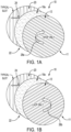
- Figs. 1A-1C illustrated is a top exploded view of an exemplary antenna system 10 that may be used in connection with the present invention, the antenna system 10 including a polarizer 11 for selectively switching between LHCP, RHCP and linear polarization.
- Figs. 1A and 1B illustrates the polarizer 11 configured for circular polarization (LHCP or RHCP), and
- Fig. 1C illustrates the polarizer configured for the "inert" state (linear polarization from which a combination of both LHCP and RHCP is simultaneously derived).
- the antenna system 10 includes an antenna with a linearly-polarized aperture 20 for transmitting and receiving a signal.
- the linearly-polarized aperture 20 is a variable inclination continuous transverse stub (VICTS) antenna.
- VIPCTS variable inclination continuous transverse stub
- the system and method in accordance with the invention can be used with other types of linearly-polarized apertures.
- the exemplary polarizer 11 of Figs. 1A-1C comprises a meander-line polarizer 12 spaced apart from the linearly polarized aperture 20 to define a gap 22 formed between the meander-line polarizer 12 and the aperture 20.
- Air or a foam spacer 18a resides in the gap 22.
- a purpose of the optional foam spacer 18a, which may be formed from low-density foam, is to maintain a constant spacing between the meander-line polarizer 12 and the aperture 20, however other methods of maintaining such spacing are possible.
- a perspective view along with section views of an exemplary meander-line polarizer 12 that may be used with the system and method in accordance with the invention.
- the exemplary meander-line polarizer 12 has a circular form factor to facilitate rotation of the meander-line polarizer and the antenna aperture 20 about a common axis.
- a benefit of using a circular form factor is that it ensures the surface area of the meander-line polarizer, when the polarizer is arranged on a common axis through the center of the aperture 20, completely overlap regardless of the angular orientation of the polarizer relative to the aperture.
- each layer is formed from three individual layers, 13a, 13b, 13c, each layer arranged parallel to the other and spaced apart by a preset distance.
- Each layer includes a plurality of meander-line traces 15a formed on a substrate 15b, with a spacer 15c arranged between adjacent substrates.
- the exemplary meander-line polarizer 12 of Fig. 2 includes three layers, it is possible to utilize a meander-line polarizer 12 with less layers (e.g., two layers) or more than three layers (e.g., four, five, six or more layers.)
- Meander-line polarizers are generically designed to provide the typical "quadrature" (90 degree) differential transmission phase difference between parallel and perpendicular incident linearly-polarized wave components, relative to a common axes of the meander-line traces 15a.
- incident linear polarization is converted to circular polarization when the incident linear polarization is oriented at approximately +45 or -45 degrees relative to these axes (thereby presenting approximately equal magnitudes of parallel and perpendicular field components.)
- reference to an “approximate” angular orientation includes the specified angular orientation plus or minus 15 degrees.
- “approximately +45 degrees or - 45 degrees” includes +60 to +30 degrees or -30 degrees to -60 degrees, respectively.
- the polarizer 12 is rotated/oriented such that a longitudinal axis of the meander-lines of the polarizer 12 are approximately +45 or -45 degrees relative to the "natural" polarization 24 (also referred to as the E-field) of the antenna aperture 20.
- the polarizer 12 is rotated/oriented such that the longitudinal axis of the meander-lines of the polarizer 12 are approximately +45 degrees relative to the "natural" polarization 24 of the antenna aperture 20. This essentially "activates” the polarizer 12 such that it converts the intrinsic linear polarization of the aperture 20 to RHCP.
- the polarizer 12 is rotated/oriented such that the longitudinal axis of the meander-lines of the polarizer 12 are approximately -45 degrees relative to the natural polarization 24 of the antenna aperture 20. This essentially "activates” the polarizer 12 such that it converts the intrinsic linear polarization of the aperture 20 to LHCP 28b.
- Fig. 1C illustrates the meander-lines of the inner polarizer at approximately 0 degrees relative to the natural polarization 24 of the antenna aperture 20. This essentially "deactivates" the polarizer 12 such that it has no primary polarization impact (i.e., the inert condition). As a result, linear-polarization is passed through and unchanged from the linear polarized aperture 20.
- independent motion control of the meander-line polarizer 12 relative to the aperture 20 ensures that the desired polarization can be achieved.
- Such motion can be accomplished by direct drive, gear drive, belt drive, or other common rotation methods in order to change an angular relationship between the aperture and the polarizer.
- the polarizer 12 may be mounted on a spindle 30 and rotatable about the spindle, and a motive device 32 may be drivingly coupled to the meander-line polarizer 12 .
- the motive device 32 may be an electric motor, for example, or like device, and may be coupled to the polarizer via a drive coupler 36, such as a belt drive, a gear drive, a screw drive, spindle drive or the like.
- a controller 38 which includes, for example, a processor and memory or an application specific integrated circuit, is configured to implement a method in accordance with the invention.
- the controller 38 communicates with the actuator 32 to rotate the polarizer 12 to produce desired orientations (e.g., the controller is configured to selectively command the motive device(s) to position the polarizer relative to the aperture to produce any one of the polarization.)
- One or more feedback devices (not shown) operatively coupled to the polarizer 12 and communicatively coupled to the controller 38 enable closed loop position control.
- the described meander-line polarizer is employed in a novel non-conventional manner to exploit the intermediate "inert” rotation angles and temporarily realize simultaneous dual circular polarization.
- the system and method in accordance with the invention "boosts" the capability of a much simpler, less complex, less bulky, and less expensive single fixed linear polarization antenna to provide not only RHCP or LHCP polarization, but also dual simultaneous RHCP and LHCP polarization senses.
- polarization in addition to frequency, to differentiate communication signals.
- FIG. 4 illustrated is an exemplary application in which cell coverage of the United States is provided via multiple spot beams 50, each spot beam utilizing LHCP or RHCP and an operating of frequency f1 or f2.
- adjacent spot beams utilize the same frequency and polarization, e.g., f1 and LHCP, and therefore the transition of a mobile device between such spot beams requires no change in polarization or frequency.
- a different polarization and frequency e.g., RHCP and f2
- two or more adjacent spot beams 50a, 50b, 50c may have different polarizations and operate at different frequencies.
- spot beams 50a and 50c may operate with RHCP 52a and frequency f1 and spot beam 50b may operate with LHCP 52b and at frequency f2.
- the adjacent spot beams have regions of overlap, and when such overlap occurs between spot beams having different polarizations, zones of "dual polarization" 54 are created.
- the mobile device transitions from spot beam 50a to spot beam 50b and then to spot beam 50c.
- the mobile device must adapt to the change in polarization at each spot beam, and in particular must be capable of simultaneous LHCP and RHCP in the overlapping regions in order to connect to both beams simultaneously (and thus enable seamless transfer between beams).
- a mobile device requires simultaneous LHCP and RHCP in overlapping regions 60.
- "narrow" spot beams 62a, 62b, 62c provide, for example, cellular communication capability while a "wide" overlay beam 64 provides broadcast capability.
- the spot beams 62a, 62b, 62c operate using the same polarity, e.g., LHCP, with different frequencies f1, f2, while the broadcast overlay beam 64 operates using a polarity and frequency different from the spot beams, e.g., RHCP and f3.
- the mobile device must be capable of receiving the different polarization signals in order to provide both broadcast reception and cellular communication functions.
- the system and method in accordance with the invention can exploit the satellite network examples of Figs. 5 and 6 to support instantaneous dual polarization for multichannel communication using a simple and inexpensive polarizer.
- the system and method in accordance with the invention enable simultaneous LHCP and RHCP operation to provide seamless transition between adjacent spot beams having different polarizations and frequencies, and can do so in a highly cost-effective manner.
- LHCP left-hand circular polarization
- RHCP right-hand circular polarization
- third polarization state having linear polarization from which a combination of both LHCP and RHCP is simultaneously derived As used herein, "primarily" a first or second polarization state is defined as the signal is greater than or equal to 95 percent pure. Additionally, as used herein "strictly" LHCP or RHCP is defined as the signal is greater than or equal to 99 percent pure.
- One or more of the steps illustrated in Fig. 6 may be executed by the controller 38.
- step 72 it is determined if the mobile device will be connecting to signals provided only by spot beams or to signals provided by a combination of spot beams and a broadcast overlay. Such determination may be made, for example, based on a mode of operation of the mobile device. For example, if the mobile device is not operating in a broadcast receive mode, then it may be determined that the mobile device will only need to connect to spot beams. Conversely, if the mobile device is operating on in a broadcast receive mode, then it may be determined that the mobile device will need to connect to both the broadcast overlay and the spot beam(s).
- step 74 it is determined if the mobile device is in a region in which the signal is supplied by a single spot beam, or by overlapping spot beams that use different polarizations (e.g., an overlap region). Such determination may be made based on a detected geographical location of the mobile device (which may be obtained from a GPS) in combination with coverage data that details the service for the geographical location. Such coverage data may be pre-stored on the mobile device or retrievable by the mobile device from a remote location.
- the method moves to step 76 where the polarizer is placed in the first or second polarization state to provide primarily one of LHCP or RHCP.
- the polarizer may be placed in the first polarization state by orienting a longitudinal axis of the plurality of meander-lines at a non-zero angle with respect to a polarization orientation of the aperture (e.g., approximately 45 degrees or approximately -45 degrees relative to the natural polarization of the aperture).
- Selection of the first or second polarization state is based on a type of polarization employed by a spot beam serving an area in which the mobile device resides. Such orientation enables the mobile device to connect to a spot beam having primarily one of LHCP or RHCP. The method then moves back to step 72 and repeats.
- the polarizer is placed in the third "inert" polarization state to enable simultaneous transmission and/or reception of two different polarization signals, where a first signal of the two different signals has primarily LHCP and a second signal of the two different signals has primarily RHCP.
- the polarizer may be placed in the third polarization state by orienting a longitudinal axis of the plurality of meander-lines parallel to the polarization orientation of the E-field of the aperture.
- the polarizer may be placed in the third polarization state by orienting a longitudinal axis of the plurality of meander-lines perpendicular to the polarization orientation of the E-field of the aperture. In this manner, both LHCP and RHCP signals can be received and/or transmitted by the mobile device. This provides seamless coverage for a mobile device transitioning between adjacent spot beams that employ different polarizations. The method then moves back to step 72 and repeats.
- step 72 if the mobile device is to receive signals from spot beams and the broadcast overlay, then the method moves to step 78 as described above and the polarizer is set in the inert positon (both LHCP and RHCP). This provides simultaneous reception of spot beam transmission patterns and overlay transmission patterns in regions where the overlay beam employs a different polarization from that of the spot beams. The method then moves back to step 72 and repeats.
- the system and method in accordance with the present invention provide seamless transitioning of a user device between i) adjacent spot beams that operate using different polarities and ii) spot beams that overlap with a broadcast overlay beam that operate using different polarities.
- the transitioning method does have a slight drawback in that there is a gain loss (3dB) while operating under dual (LHCP and RHCP) polarization mode.
- This 3 dB gain loss is applied to both the LHCP signal and the RHCP signal (assuming the polarizer is set in the completely inert state, e.g., for a meander-line polarizer the meander-lines are set at 0 or 90 degrees with respect to the natural polarization of the aperture).
- the level of polarization may be advantageous to bias the level of polarization to favor one of LHCP or RHCP over the other in order to better accommodate the relative signal strengths/gains of the two overlapping beams (i.e., the overlapping regions between adjacent spot beams, or spot beams overlapping a broader broadcast beam).
- This can be beneficial when the particular location within the overlapping region between adjacent beams is farther from one boundary than the other (e.g., the mobile device/user is not in the "middle" of an overlapping region, but instead is closer to the center of one spot beam than the center of the other), in which case the signal is higher for the "closer to center” spot beam.
- spot beams overlapping with broadcast beams it is often the case that the broadcast beam can be adequately received at a lower gain level/threshold than what is required for reliable operation in the spot beam.
- 1B and 1C would provide for a different apportionment (80% LHCP, 20% RHCP, for this specific example) that "favors" (emphasizes) the LHCP over the RHCP, with the LHCP suffering a smaller (1 dB, i.e. 20%) loss while the RHCP suffers a larger (7 dB, i.e. 80%) loss.
- this (re)apportionment can be continuously controlled as the user transitions between beams (or conversely, the beams transition between the user device).
- the present invention finds particular utility in commercial and non-commercial satellite communication terminals for which highly flexible polarization capabilities provide for a single common antenna/terminal (enabled with polarization diverse capabilities) to support a broad(er) range of satellite types, including both Geosynchronous Orbit (GSO) and non-Geosynchronous Orbit (NGSO) varieties (which typically require different types of antenna polarizations and orientations.)
- GSO Geosynchronous Orbit
- NGSO non-Geosynchronous Orbit
- Terrestrial communication radios/terminals and High-Performance Radar Systems would also benefit.
- Figs. 5 and 6 illustrate two applications in which a moving user (e.g., an aircraft, a vehicle, a mobile phone, a tablet computer, etc.) transitions between fixed (static) beams emanating from fixed GSO satellites
- a moving user e.g., an aircraft, a vehicle, a mobile phone, a tablet computer, etc.
- aspects of the invention are also applicable to the opposite condition. More specifically, in the case of NGSO satellites, the beams emanating from each NGSO satellite is moving relative to the earth's surface while the user may be positionally fixed relative to the earth's surface (i.e., the user is not moving or not moving a significant distance relative to the beam width).
- the method and system in accordance with the invention can be utilized in the same manner as the GSO satellite/roaming user example discussed above to provide seamless transition between beams.
Landscapes
- Engineering & Computer Science (AREA)
- Computer Networks & Wireless Communication (AREA)
- Signal Processing (AREA)
- Physics & Mathematics (AREA)
- Astronomy & Astrophysics (AREA)
- Aviation & Aerospace Engineering (AREA)
- General Physics & Mathematics (AREA)
- Variable-Direction Aerials And Aerial Arrays (AREA)
Claims (15)
- Verfahren zum Bereitstellen eines simultanen Doppelpolarisationsbetriebs unter Verwendung einer linear polarisierten Planarantenne und eines Polarisators (11, 12), der von der linear polarisierten Planarantenne beabstandet ist, wobei der Polarisator (11, 12) einen ersten Polarisationszustand, der hauptsächlich eine linksdrehende zirkulare Polarisation (LHCP) umfasst, einen zweiten Polarisationszustand, der hauptsächlich eine rechtsdrehende zirkulare Polarisation (RHCP) umfasst, und einen dritten Zwischenpolarisationszustand, der eine lineare Polarisation umfasst, von der eine Kombination von sowohl LHCP als auch RHCP simultan abgeleitet wird, aufweist, wobei das Verfahren umfasst:Einstellen des Polarisators (11, 12) in den ersten oder zweiten Polarisationszustand, um ein Signal mit hauptsächlich entweder LHCP oder RHCP zu senden und/oder zu empfangen;Einstellen des Polarisators (11, 12) in den dritten Zwischenpolarisationszustand, um simultan zwei verschiedene Signale zu senden und/oder zu empfangen, wobei ein erstes Signal der zwei verschiedenen Signale hauptsächlich LHCP aufweist und ein zweites Signal der zwei verschiedenen Signale hauptsächlich RHCP aufweist; undEmpfangen und Senden von Funkfrequenzsignalen zwischen der linear polarisierten Planarantenne und einer elektronischen Vorrichtung, während sich der Polarisator (11, 12) in dem dritten Zwischenpolarisationszustand befindet.
- Verfahren nach Anspruch 1, ferner umfassend ein Bereitstellen einer nahtlosen Überdeckung für die elektronische Vorrichtung beim Übergang zwischen benachbarten Punktstrahlen (50, 50a-50c) durchEinstellen des Polarisators (11, 12) in den ersten Polarisationszustand oder den zweiten Polarisationszustand auf der Grundlage eines Polarisationstyps, der von einem Punktstrahl (50, 50a-50c) verwendet wird, der einen Bereich versorgt, in dem sich die elektronische Vorrichtung befindet; undEinstellen des Polarisators (11, 12) in den dritten Zwischenpolarisationszustand, wenn sich die elektronische Vorrichtung in einem Bereich befindet, der von zwei Punktstrahlen versorgt wird, die unterschiedliche Polarisationen verwenden.
- Verfahren nach Anspruch 1, wobei Punktstrahlübertragungsmuster (62a-62c) einen ersten Polarisationszustand verwenden und ein Überlagerungsübertragungsmuster (64) einen zweiten Polarisationszustand verwendet, der sich von dem ersten Polarisationszustand unterscheidet, wobei das Verfahren ferner ein Bereitstellen eines gleichzeitigen Empfangs von Punktstrahlübertragungsmustern (62a-62c) und Überlagerungsübertragungsmustern (64) durch Einstellen des Polarisators (11, 12) in den dritten Zwischenpolarisationszustand umfasst.
- Verfahren nach einem der Ansprüche 1-3, wobei das Einstellen des Polarisators (11, 12) in den dritten Zwischenpolarisationszustand ein Einstellen des Polarisators (11, 12) in einen Zustand umfasst, der eine von LHCP oder RHCP gegenüber der anderen von LHCP oder RHCP hervorhebt.
- Verfahren nach Anspruch 4, wenn es von Anspruch 2 abhängt, wobei das Einstellen des Polarisators (11, 12) in einen Zustand, der eine von LHCP oder RHCP gegenüber der anderen von LHCP oder RHCP hervorhebt, umfasst:Bestimmen eines Abstands der elektronischen Vorrichtung von einer nächstgelegenen äußeren Begrenzung von jedem von zwei benachbarten Punktstrahlen (50, 50a-50c);Bestimmen einer Polarisation des Punktstrahls (50, 50a-50c), der eine äußere Begrenzung aufweist, die am weitesten von einem Ort der elektronischen Vorrichtung entfernt ist; undEinstellen des Polarisators (11, 12) in einen Zustand, der eine Polarisation des Punktstrahls (50, 50a-50c) hervorhebt, der die äußere Begrenzung aufweist, die am weitesten von dem Ort der elektronischen Vorrichtung entfernt ist.
- Verfahren nach einem der Ansprüche 1 bis 5, wobei der zweite Polarisationszustand genau eine von LHCP oder RHCP ist und/oder der erste Polarisationszustand genau eine von LHCP oder RHCP ist.
- Verfahren nach einem der Ansprüche 1-6, ferner umfassend ein Verwenden eines Mäanderlinien-Polarisators (12), eines Drehflügel-Polarisators, eines Orthomoden-Wandler-Polarisators und/oder eines Viertelwellenplatten-Polarisators, um jeden Polarisationszustand bereitzustellen.
- Verfahren nach Anspruch 7, wobei das Verwenden ein Verwenden des Mäanderlinien-Polarisators (12) umfasst,wobei der Mäanderlinien-Polarisator (12) mehrere Mäanderlinien umfasst und die linear polarisierte Planarantenne eine Apertur (20) umfasst, undwobei das Einstellen des Polarisators (12) in den dritten Zwischenpolarisationszustand ein Ausrichten einer Längsachse der mehreren Mäanderlinien parallel zu der Polarisationsausrichtung des E-Feldes der Apertur (20) umfasst.
- Verfahren nach Anspruch 7, wobei das Verwenden ein Verwenden des Mäanderlinien-Polarisators (12) umfasst,wobei der Mäanderlinien-Polarisator (12) mehrere Mäanderlinien umfasst und die linear polarisierte Planarantenne eine Apertur (20) umfasst, undwobei das Einstellen des Polarisators (12) in den dritten Zwischenpolarisationszustand ein Ausrichten einer Längsachse der mehreren Mäanderlinien senkrecht zu der Polarisationsausrichtung des E-Feldes der Apertur (20) umfasst.
- Verfahren nach einem der Ansprüche 7-9, wobei der Mäanderlinien-Polarisator (12) mehrere Mäanderlinien umfasst und die linear polarisierte Planarantenne eine Apertur (20) umfasst, und
wobei das Einstellen des Polarisators (12) in den ersten oder zweiten Polarisationszustand ein Ausrichten einer Längsachse der mehreren Mäanderlinien in einem von Null verschiedenen Winkel in Bezug auf eine Polarisationsausrichtung der Apertur (20) umfasst. - System (10) zum Bereitstellen einer Doppelpolarisationsfunktionalität, umfassend:eine linear polarisierte Planarantenne mit einer Apertur (20);einen Polarisator (11, 12), der von der linear polarisierten Planarantenne beabstandet ist, wobei der Polarisator einen ersten Polarisationszustand, der hauptsächlich eine linksdrehende zirkulare Polarisation (LHCP) oder rechtsdrehende zirkulare Polarisation (RHCP) umfasst, und einen dritten Zwischenpolarisationszustand, der eine lineare Polarisation umfasst, die aus einer Kombination von LHCP und RHCP abgeleitet ist, aufweist;eine Steuerung (38), die funktionsfähig mit dem Polarisator (11, 12) gekoppelt ist, wobei die Steuerung (38) ausgestaltet ist, um den Polarisator (11, 12) in den ersten Polarisationszustand einzustellen, um hauptsächlich entweder einen LHCP-Betrieb oder einen RHCP-Betrieb bereitzustellen, den Polarisator (11, 12) in den dritten Zwischenpolarisationszustand einzustellen, um einen gleichzeitigen LHCP- und RHCP-Betrieb bereitzustellen, und Funkfrequenzsignale zwischen der linear polarisierten Planarantenne und einer elektronischen Vorrichtung zu empfangen und zu senden, während sich der Polarisator (11, 12) in dem dritten Zwischenpolarisationszustand befindet.
- System (10) nach Anspruch 11, wobei der Polarisator (11, 12) eine Antriebsvorrichtung (32) umfasst, die kommunikationsmäßig mit der Steuerung (38) gekoppelt ist und dazu dient, den Polarisator (11, 12) selektiv relativ zu der Apertur (20) zu positionieren, wobei die Steuerung (38) ausgestaltet ist, die Antriebsvorrichtung (32) selektiv anzuweisen, den Polarisator (11, 12) relativ zu der Apertur (20) zu positionieren, um einen der Polarisationszustände zu erzeugen.
- System (10) nach Anspruch 11, wobei der Polarisator (11) einen Mäanderlinien-Polarisator (12) umfasst, der mehrere Mäanderlinien aufweist, und wobei die Steuerung (38) ausgestaltet ist, um den Mäanderlinien-Polarisator (12) in den dritten Zwischenpolarisationszustand einzustellen, indem sie die Antriebsvorrichtung (32) anweist, eine Längsachse der mehreren Mäanderlinien parallel zu der Polarisationsausrichtung des E-Feldes der Apertur (20) auszurichten.
- System (10) nach Anspruch 11, wobei der Polarisator (11) einen Mäanderlinien-Polarisator (12) umfasst, der mehrere Mäanderlinien aufweist, und wobei die Steuerung (38) ausgestaltet ist, um den Mäanderlinien-Polarisator (12) in den dritten Zwischenpolarisationszustand einzustellen, indem sie die Antriebsvorrichtung (32) anweist, eine Längsachse der mehreren Mäanderlinien senkrecht zu der Polarisationsausrichtung des E-Feldes der Apertur (20) auszurichten.
- System (10) nach einem der Ansprüche 13-14, wobei die Steuerung (38) ausgestaltet ist, um den Mäanderlinien-Polarisator (12) in den ersten Polarisationszustand einzustellen, indem sie die Antriebsvorrichtung (32) anweist, eine Längsachse der mehreren Mäanderlinien in einem von Null verschiedenen Winkel in Bezug auf eine Polarisationsausrichtung der Apertur auszurichten.
Applications Claiming Priority (1)
| Application Number | Priority Date | Filing Date | Title |
|---|---|---|---|
| US16/775,375 US11088463B1 (en) | 2020-01-29 | 2020-01-29 | Realization and application of simultaneous circular polarization in switchable single polarization systems |
Publications (2)
| Publication Number | Publication Date |
|---|---|
| EP3859986A1 EP3859986A1 (de) | 2021-08-04 |
| EP3859986B1 true EP3859986B1 (de) | 2023-11-22 |
Family
ID=74236045
Family Applications (1)
| Application Number | Title | Priority Date | Filing Date |
|---|---|---|---|
| EP21153223.9A Active EP3859986B1 (de) | 2020-01-29 | 2021-01-25 | Realisierung und anwendung von simultaner zirkularer polarisation in schaltbaren einzelpolarisationssystemen |
Country Status (5)
| Country | Link |
|---|---|
| US (1) | US11088463B1 (de) |
| EP (1) | EP3859986B1 (de) |
| CA (1) | CA3106919C (de) |
| ES (1) | ES2972818T3 (de) |
| IL (1) | IL280380B2 (de) |
Families Citing this family (3)
| Publication number | Priority date | Publication date | Assignee | Title |
|---|---|---|---|---|
| KR102409154B1 (ko) * | 2020-12-08 | 2022-06-14 | 중앙대학교 산학협력단 | 동일 대역 전이중 방식의 다중 안테나 및 이를 포함하는 송수신 장치 |
| CN117335169B (zh) * | 2023-09-07 | 2024-04-19 | 苏州欣天盛科技有限公司 | 用于5g毫米波系统的双频双圆极化透射阵天线及方法 |
| EP4633059A1 (de) * | 2024-04-10 | 2025-10-15 | Deutsche Telekom AG | Verfahren, computerprogramm, vorrichtung und satellit zur drahtlosen datenkommunikation in einem kommunikationssystem |
Family Cites Families (16)
| Publication number | Priority date | Publication date | Assignee | Title |
|---|---|---|---|---|
| US3215957A (en) | 1962-03-05 | 1965-11-02 | Bendix Corp | Variable polarization for microwaves |
| US3581242A (en) | 1969-10-20 | 1971-05-25 | Us Air Force | Variable polarizer for microwave systems |
| US4716415A (en) * | 1984-12-06 | 1987-12-29 | Kelly Kenneth C | Dual polarization flat plate antenna |
| US6369868B1 (en) | 1998-06-05 | 2002-04-09 | Reveo, Inc. | Liquid crystal polarizer with electrically controllable bandwidth |
| US5337058A (en) | 1993-04-16 | 1994-08-09 | United Technologies Corporation | Fast switching polarization diverse radar antenna system |
| US6452561B1 (en) | 2001-03-28 | 2002-09-17 | Rockwell Collins, Inc. | High-isolation broadband polarization diverse circular waveguide feed |
| US6507323B1 (en) | 2001-03-28 | 2003-01-14 | Rockwell Collins, Inc. | High-isolation polarization diverse circular waveguide orthomode feed |
| US20050062661A1 (en) * | 2001-04-13 | 2005-03-24 | Zagiiloul Amir I | Dual circular polarization flat plate antenna that uses multilayer structure with meander line polarizer |
| US6563470B2 (en) | 2001-05-17 | 2003-05-13 | Northrop Grumman Corporation | Dual band frequency polarizer using corrugated geometry profile |
| US7642978B2 (en) * | 2007-03-30 | 2010-01-05 | Itt Manufacturing Enterprises, Inc. | Method and apparatus for steering and stabilizing radio frequency beams utilizing photonic crystal structures |
| US8339326B2 (en) | 2008-10-20 | 2012-12-25 | Ems Technologies, Inc. | Antenna polarization control |
| WO2010120767A2 (en) | 2009-04-13 | 2010-10-21 | Viasat, Inc. | Active feed forward amplifier |
| US9941594B2 (en) * | 2014-12-11 | 2018-04-10 | Thinkom Solutions, Inc. | Inscribed polarizer array for polarization diverse application |
| US9972915B2 (en) * | 2014-12-12 | 2018-05-15 | Thinkom Solutions, Inc. | Optimized true-time delay beam-stabilization techniques for instantaneous bandwith enhancement |
| US10931024B2 (en) * | 2019-03-29 | 2021-02-23 | Thinkom Solutions, Inc. | Linear-to-CP polarizer with enhanced performance in VICTS antennas |
| US10819022B1 (en) * | 2019-10-01 | 2020-10-27 | Thinkom Solutions, Inc. | Partitioned variable inclination continuous transverse stub array |
-
2020
- 2020-01-29 US US16/775,375 patent/US11088463B1/en active Active
-
2021
- 2021-01-25 IL IL280380A patent/IL280380B2/en unknown
- 2021-01-25 CA CA3106919A patent/CA3106919C/en active Active
- 2021-01-25 EP EP21153223.9A patent/EP3859986B1/de active Active
- 2021-01-25 ES ES21153223T patent/ES2972818T3/es active Active
Also Published As
| Publication number | Publication date |
|---|---|
| EP3859986A1 (de) | 2021-08-04 |
| ES2972818T3 (es) | 2024-06-17 |
| CA3106919A1 (en) | 2021-07-29 |
| IL280380B2 (en) | 2024-09-01 |
| IL280380B1 (en) | 2024-05-01 |
| IL280380A (en) | 2021-07-29 |
| US11088463B1 (en) | 2021-08-10 |
| CA3106919C (en) | 2024-04-30 |
Similar Documents
| Publication | Publication Date | Title |
|---|---|---|
| US7161537B2 (en) | Low profile hybrid phased array antenna system configuration and element | |
| US7102571B2 (en) | Offset stacked patch antenna and method | |
| EP3859986B1 (de) | Realisierung und anwendung von simultaner zirkularer polarisation in schaltbaren einzelpolarisationssystemen | |
| US8587492B2 (en) | Dual-polarized multi-band, full duplex, interleaved waveguide antenna aperture | |
| US7123876B2 (en) | Easy set-up, vehicle mounted, in-motion tracking, satellite antenna | |
| US6657589B2 (en) | Easy set-up, low profile, vehicle mounted, in-motion tracking, satellite antenna | |
| EP3716405B1 (de) | Linear-zu-cp-polarisator mit verbesserter leistung in victs-antennen | |
| JP5786244B2 (ja) | 車載指向性平板アンテナ、かかるアンテナを含む車両、およびかかる車両を含む衛星通信システム | |
| JP4027967B2 (ja) | 偏波切換・指向性可変アンテナ | |
| US20020167449A1 (en) | Low profile phased array antenna | |
| US9941594B2 (en) | Inscribed polarizer array for polarization diverse application | |
| WO2006028589A1 (en) | Antenna system | |
| US12388186B2 (en) | Antenna assembly | |
| EP3826111A1 (de) | Breitbandiger polarisationsdiversitätspolarisator mit verbesserten schaltbaren dualen polarisationseigenschaften | |
| US20090195329A1 (en) | Variable phase shifter | |
| Luo et al. | Smart antennas for satellite communications on the move | |
| US11682842B1 (en) | Log periodic array application of minature active differential/quadrature radiating elements | |
| Murata et al. | A self-steering planar array antenna for satellite broadcast reception | |
| Woo et al. | Performance of a family of omni and steered antennas for mobile satellite applications | |
| JPH09230018A (ja) | 自動追尾アンテナ | |
| WO2025257647A1 (en) | Rf frontend for universal 5g/6g and leo satellite communication | |
| Fujita et al. | Experimental results on multi-beam receiving antenna for satellite broadcasting | |
| Fujita et al. | A Polarization Control for a Multi-beam DBS Receiving Antenna | |
| JPH04242302A (ja) | 平面アレイアンテナ | |
| JPH01162401A (ja) | 衛星放送用のダイバシティ受信装置 |
Legal Events
| Date | Code | Title | Description |
|---|---|---|---|
| PUAI | Public reference made under article 153(3) epc to a published international application that has entered the european phase |
Free format text: ORIGINAL CODE: 0009012 |
|
| STAA | Information on the status of an ep patent application or granted ep patent |
Free format text: STATUS: THE APPLICATION HAS BEEN PUBLISHED |
|
| AK | Designated contracting states |
Kind code of ref document: A1 Designated state(s): AL AT BE BG CH CY CZ DE DK EE ES FI FR GB GR HR HU IE IS IT LI LT LU LV MC MK MT NL NO PL PT RO RS SE SI SK SM TR |
|
| STAA | Information on the status of an ep patent application or granted ep patent |
Free format text: STATUS: REQUEST FOR EXAMINATION WAS MADE |
|
| 17P | Request for examination filed |
Effective date: 20220111 |
|
| RBV | Designated contracting states (corrected) |
Designated state(s): AL AT BE BG CH CY CZ DE DK EE ES FI FR GB GR HR HU IE IS IT LI LT LU LV MC MK MT NL NO PL PT RO RS SE SI SK SM TR |
|
| GRAP | Despatch of communication of intention to grant a patent |
Free format text: ORIGINAL CODE: EPIDOSNIGR1 |
|
| STAA | Information on the status of an ep patent application or granted ep patent |
Free format text: STATUS: GRANT OF PATENT IS INTENDED |
|
| INTG | Intention to grant announced |
Effective date: 20230707 |
|
| GRAS | Grant fee paid |
Free format text: ORIGINAL CODE: EPIDOSNIGR3 |
|
| GRAA | (expected) grant |
Free format text: ORIGINAL CODE: 0009210 |
|
| STAA | Information on the status of an ep patent application or granted ep patent |
Free format text: STATUS: THE PATENT HAS BEEN GRANTED |
|
| AK | Designated contracting states |
Kind code of ref document: B1 Designated state(s): AL AT BE BG CH CY CZ DE DK EE ES FI FR GB GR HR HU IE IS IT LI LT LU LV MC MK MT NL NO PL PT RO RS SE SI SK SM TR |
|
| P01 | Opt-out of the competence of the unified patent court (upc) registered |
Effective date: 20231013 |
|
| REG | Reference to a national code |
Ref country code: GB Ref legal event code: FG4D |
|
| REG | Reference to a national code |
Ref country code: CH Ref legal event code: EP |
|
| REG | Reference to a national code |
Ref country code: DE Ref legal event code: R096 Ref document number: 602021006925 Country of ref document: DE |
|
| REG | Reference to a national code |
Ref country code: IE Ref legal event code: FG4D |
|
| REG | Reference to a national code |
Ref country code: LT Ref legal event code: MG9D |
|
| REG | Reference to a national code |
Ref country code: NL Ref legal event code: MP Effective date: 20231122 |
|
| PG25 | Lapsed in a contracting state [announced via postgrant information from national office to epo] |
Ref country code: GR Free format text: LAPSE BECAUSE OF FAILURE TO SUBMIT A TRANSLATION OF THE DESCRIPTION OR TO PAY THE FEE WITHIN THE PRESCRIBED TIME-LIMIT Effective date: 20240223 |
|
| PG25 | Lapsed in a contracting state [announced via postgrant information from national office to epo] |
Ref country code: IS Free format text: LAPSE BECAUSE OF FAILURE TO SUBMIT A TRANSLATION OF THE DESCRIPTION OR TO PAY THE FEE WITHIN THE PRESCRIBED TIME-LIMIT Effective date: 20240322 |
|
| PG25 | Lapsed in a contracting state [announced via postgrant information from national office to epo] |
Ref country code: LT Free format text: LAPSE BECAUSE OF FAILURE TO SUBMIT A TRANSLATION OF THE DESCRIPTION OR TO PAY THE FEE WITHIN THE PRESCRIBED TIME-LIMIT Effective date: 20231122 |
|
| REG | Reference to a national code |
Ref country code: AT Ref legal event code: MK05 Ref document number: 1634807 Country of ref document: AT Kind code of ref document: T Effective date: 20231122 |
|
| PG25 | Lapsed in a contracting state [announced via postgrant information from national office to epo] |
Ref country code: NL Free format text: LAPSE BECAUSE OF FAILURE TO SUBMIT A TRANSLATION OF THE DESCRIPTION OR TO PAY THE FEE WITHIN THE PRESCRIBED TIME-LIMIT Effective date: 20231122 |
|
| PG25 | Lapsed in a contracting state [announced via postgrant information from national office to epo] |
Ref country code: AT Free format text: LAPSE BECAUSE OF FAILURE TO SUBMIT A TRANSLATION OF THE DESCRIPTION OR TO PAY THE FEE WITHIN THE PRESCRIBED TIME-LIMIT Effective date: 20231122 |
|
| PG25 | Lapsed in a contracting state [announced via postgrant information from national office to epo] |
Ref country code: NL Free format text: LAPSE BECAUSE OF FAILURE TO SUBMIT A TRANSLATION OF THE DESCRIPTION OR TO PAY THE FEE WITHIN THE PRESCRIBED TIME-LIMIT Effective date: 20231122 Ref country code: LT Free format text: LAPSE BECAUSE OF FAILURE TO SUBMIT A TRANSLATION OF THE DESCRIPTION OR TO PAY THE FEE WITHIN THE PRESCRIBED TIME-LIMIT Effective date: 20231122 Ref country code: IS Free format text: LAPSE BECAUSE OF FAILURE TO SUBMIT A TRANSLATION OF THE DESCRIPTION OR TO PAY THE FEE WITHIN THE PRESCRIBED TIME-LIMIT Effective date: 20240322 Ref country code: GR Free format text: LAPSE BECAUSE OF FAILURE TO SUBMIT A TRANSLATION OF THE DESCRIPTION OR TO PAY THE FEE WITHIN THE PRESCRIBED TIME-LIMIT Effective date: 20240223 Ref country code: BG Free format text: LAPSE BECAUSE OF FAILURE TO SUBMIT A TRANSLATION OF THE DESCRIPTION OR TO PAY THE FEE WITHIN THE PRESCRIBED TIME-LIMIT Effective date: 20240222 Ref country code: AT Free format text: LAPSE BECAUSE OF FAILURE TO SUBMIT A TRANSLATION OF THE DESCRIPTION OR TO PAY THE FEE WITHIN THE PRESCRIBED TIME-LIMIT Effective date: 20231122 Ref country code: PT Free format text: LAPSE BECAUSE OF FAILURE TO SUBMIT A TRANSLATION OF THE DESCRIPTION OR TO PAY THE FEE WITHIN THE PRESCRIBED TIME-LIMIT Effective date: 20240322 |
|
| PG25 | Lapsed in a contracting state [announced via postgrant information from national office to epo] |
Ref country code: SE Free format text: LAPSE BECAUSE OF FAILURE TO SUBMIT A TRANSLATION OF THE DESCRIPTION OR TO PAY THE FEE WITHIN THE PRESCRIBED TIME-LIMIT Effective date: 20231122 Ref country code: RS Free format text: LAPSE BECAUSE OF FAILURE TO SUBMIT A TRANSLATION OF THE DESCRIPTION OR TO PAY THE FEE WITHIN THE PRESCRIBED TIME-LIMIT Effective date: 20231122 Ref country code: PL Free format text: LAPSE BECAUSE OF FAILURE TO SUBMIT A TRANSLATION OF THE DESCRIPTION OR TO PAY THE FEE WITHIN THE PRESCRIBED TIME-LIMIT Effective date: 20231122 Ref country code: NO Free format text: LAPSE BECAUSE OF FAILURE TO SUBMIT A TRANSLATION OF THE DESCRIPTION OR TO PAY THE FEE WITHIN THE PRESCRIBED TIME-LIMIT Effective date: 20240222 Ref country code: LV Free format text: LAPSE BECAUSE OF FAILURE TO SUBMIT A TRANSLATION OF THE DESCRIPTION OR TO PAY THE FEE WITHIN THE PRESCRIBED TIME-LIMIT Effective date: 20231122 Ref country code: HR Free format text: LAPSE BECAUSE OF FAILURE TO SUBMIT A TRANSLATION OF THE DESCRIPTION OR TO PAY THE FEE WITHIN THE PRESCRIBED TIME-LIMIT Effective date: 20231122 |
|
| REG | Reference to a national code |
Ref country code: ES Ref legal event code: FG2A Ref document number: 2972818 Country of ref document: ES Kind code of ref document: T3 Effective date: 20240617 |
|
| PG25 | Lapsed in a contracting state [announced via postgrant information from national office to epo] |
Ref country code: DK Free format text: LAPSE BECAUSE OF FAILURE TO SUBMIT A TRANSLATION OF THE DESCRIPTION OR TO PAY THE FEE WITHIN THE PRESCRIBED TIME-LIMIT Effective date: 20231122 |
|
| PG25 | Lapsed in a contracting state [announced via postgrant information from national office to epo] |
Ref country code: CZ Free format text: LAPSE BECAUSE OF FAILURE TO SUBMIT A TRANSLATION OF THE DESCRIPTION OR TO PAY THE FEE WITHIN THE PRESCRIBED TIME-LIMIT Effective date: 20231122 |
|
| PG25 | Lapsed in a contracting state [announced via postgrant information from national office to epo] |
Ref country code: SK Free format text: LAPSE BECAUSE OF FAILURE TO SUBMIT A TRANSLATION OF THE DESCRIPTION OR TO PAY THE FEE WITHIN THE PRESCRIBED TIME-LIMIT Effective date: 20231122 |
|
| PG25 | Lapsed in a contracting state [announced via postgrant information from national office to epo] |
Ref country code: SM Free format text: LAPSE BECAUSE OF FAILURE TO SUBMIT A TRANSLATION OF THE DESCRIPTION OR TO PAY THE FEE WITHIN THE PRESCRIBED TIME-LIMIT Effective date: 20231122 Ref country code: SK Free format text: LAPSE BECAUSE OF FAILURE TO SUBMIT A TRANSLATION OF THE DESCRIPTION OR TO PAY THE FEE WITHIN THE PRESCRIBED TIME-LIMIT Effective date: 20231122 Ref country code: RO Free format text: LAPSE BECAUSE OF FAILURE TO SUBMIT A TRANSLATION OF THE DESCRIPTION OR TO PAY THE FEE WITHIN THE PRESCRIBED TIME-LIMIT Effective date: 20231122 Ref country code: EE Free format text: LAPSE BECAUSE OF FAILURE TO SUBMIT A TRANSLATION OF THE DESCRIPTION OR TO PAY THE FEE WITHIN THE PRESCRIBED TIME-LIMIT Effective date: 20231122 Ref country code: DK Free format text: LAPSE BECAUSE OF FAILURE TO SUBMIT A TRANSLATION OF THE DESCRIPTION OR TO PAY THE FEE WITHIN THE PRESCRIBED TIME-LIMIT Effective date: 20231122 Ref country code: CZ Free format text: LAPSE BECAUSE OF FAILURE TO SUBMIT A TRANSLATION OF THE DESCRIPTION OR TO PAY THE FEE WITHIN THE PRESCRIBED TIME-LIMIT Effective date: 20231122 |
|
| REG | Reference to a national code |
Ref country code: DE Ref legal event code: R097 Ref document number: 602021006925 Country of ref document: DE |
|
| PG25 | Lapsed in a contracting state [announced via postgrant information from national office to epo] |
Ref country code: MC Free format text: LAPSE BECAUSE OF FAILURE TO SUBMIT A TRANSLATION OF THE DESCRIPTION OR TO PAY THE FEE WITHIN THE PRESCRIBED TIME-LIMIT Effective date: 20231122 |
|
| PG25 | Lapsed in a contracting state [announced via postgrant information from national office to epo] |
Ref country code: MC Free format text: LAPSE BECAUSE OF FAILURE TO SUBMIT A TRANSLATION OF THE DESCRIPTION OR TO PAY THE FEE WITHIN THE PRESCRIBED TIME-LIMIT Effective date: 20231122 |
|
| REG | Reference to a national code |
Ref country code: CH Ref legal event code: PL |
|
| PG25 | Lapsed in a contracting state [announced via postgrant information from national office to epo] |
Ref country code: LU Free format text: LAPSE BECAUSE OF NON-PAYMENT OF DUE FEES Effective date: 20240125 |
|
| PLBE | No opposition filed within time limit |
Free format text: ORIGINAL CODE: 0009261 |
|
| STAA | Information on the status of an ep patent application or granted ep patent |
Free format text: STATUS: NO OPPOSITION FILED WITHIN TIME LIMIT |
|
| PG25 | Lapsed in a contracting state [announced via postgrant information from national office to epo] |
Ref country code: LU Free format text: LAPSE BECAUSE OF NON-PAYMENT OF DUE FEES Effective date: 20240125 |
|
| PG25 | Lapsed in a contracting state [announced via postgrant information from national office to epo] |
Ref country code: BE Free format text: LAPSE BECAUSE OF NON-PAYMENT OF DUE FEES Effective date: 20240131 |
|
| PG25 | Lapsed in a contracting state [announced via postgrant information from national office to epo] |
Ref country code: CH Free format text: LAPSE BECAUSE OF NON-PAYMENT OF DUE FEES Effective date: 20240131 |
|
| PG25 | Lapsed in a contracting state [announced via postgrant information from national office to epo] |
Ref country code: SI Free format text: LAPSE BECAUSE OF FAILURE TO SUBMIT A TRANSLATION OF THE DESCRIPTION OR TO PAY THE FEE WITHIN THE PRESCRIBED TIME-LIMIT Effective date: 20231122 |
|
| 26N | No opposition filed |
Effective date: 20240823 |
|
| PG25 | Lapsed in a contracting state [announced via postgrant information from national office to epo] |
Ref country code: SI Free format text: LAPSE BECAUSE OF FAILURE TO SUBMIT A TRANSLATION OF THE DESCRIPTION OR TO PAY THE FEE WITHIN THE PRESCRIBED TIME-LIMIT Effective date: 20231122 Ref country code: CH Free format text: LAPSE BECAUSE OF NON-PAYMENT OF DUE FEES Effective date: 20240131 Ref country code: BE Free format text: LAPSE BECAUSE OF NON-PAYMENT OF DUE FEES Effective date: 20240131 |
|
| REG | Reference to a national code |
Ref country code: BE Ref legal event code: MM Effective date: 20240131 |
|
| PG25 | Lapsed in a contracting state [announced via postgrant information from national office to epo] |
Ref country code: IE Free format text: LAPSE BECAUSE OF NON-PAYMENT OF DUE FEES Effective date: 20240125 |
|
| PG25 | Lapsed in a contracting state [announced via postgrant information from national office to epo] |
Ref country code: IE Free format text: LAPSE BECAUSE OF NON-PAYMENT OF DUE FEES Effective date: 20240125 |
|
| PGFP | Annual fee paid to national office [announced via postgrant information from national office to epo] |
Ref country code: DE Payment date: 20250129 Year of fee payment: 5 |
|
| PGFP | Annual fee paid to national office [announced via postgrant information from national office to epo] |
Ref country code: ES Payment date: 20250203 Year of fee payment: 5 |
|
| PGFP | Annual fee paid to national office [announced via postgrant information from national office to epo] |
Ref country code: FR Payment date: 20250127 Year of fee payment: 5 |
|
| PGFP | Annual fee paid to national office [announced via postgrant information from national office to epo] |
Ref country code: IT Payment date: 20250121 Year of fee payment: 5 Ref country code: GB Payment date: 20250127 Year of fee payment: 5 |
|
| PG25 | Lapsed in a contracting state [announced via postgrant information from national office to epo] |
Ref country code: CY Free format text: LAPSE BECAUSE OF FAILURE TO SUBMIT A TRANSLATION OF THE DESCRIPTION OR TO PAY THE FEE WITHIN THE PRESCRIBED TIME-LIMIT; INVALID AB INITIO Effective date: 20210125 |
|
| PG25 | Lapsed in a contracting state [announced via postgrant information from national office to epo] |
Ref country code: HU Free format text: LAPSE BECAUSE OF FAILURE TO SUBMIT A TRANSLATION OF THE DESCRIPTION OR TO PAY THE FEE WITHIN THE PRESCRIBED TIME-LIMIT; INVALID AB INITIO Effective date: 20210125 |
|
| PG25 | Lapsed in a contracting state [announced via postgrant information from national office to epo] |
Ref country code: FI Free format text: LAPSE BECAUSE OF FAILURE TO SUBMIT A TRANSLATION OF THE DESCRIPTION OR TO PAY THE FEE WITHIN THE PRESCRIBED TIME-LIMIT Effective date: 20231122 |
|
| PG25 | Lapsed in a contracting state [announced via postgrant information from national office to epo] |
Ref country code: TR Free format text: LAPSE BECAUSE OF FAILURE TO SUBMIT A TRANSLATION OF THE DESCRIPTION OR TO PAY THE FEE WITHIN THE PRESCRIBED TIME-LIMIT Effective date: 20231122 |