EP3859883A1 - In-vehicle antenna device - Google Patents
In-vehicle antenna device Download PDFInfo
- Publication number
- EP3859883A1 EP3859883A1 EP19867386.5A EP19867386A EP3859883A1 EP 3859883 A1 EP3859883 A1 EP 3859883A1 EP 19867386 A EP19867386 A EP 19867386A EP 3859883 A1 EP3859883 A1 EP 3859883A1
- Authority
- EP
- European Patent Office
- Prior art keywords
- antenna
- arm portions
- proximal end
- end portion
- base
- Prior art date
- Legal status (The legal status is an assumption and is not a legal conclusion. Google has not performed a legal analysis and makes no representation as to the accuracy of the status listed.)
- Pending
Links
Images



Classifications
-
- H—ELECTRICITY
- H01—ELECTRIC ELEMENTS
- H01Q—ANTENNAS, i.e. RADIO AERIALS
- H01Q1/00—Details of, or arrangements associated with, antennas
- H01Q1/27—Adaptation for use in or on movable bodies
- H01Q1/32—Adaptation for use in or on road or rail vehicles
- H01Q1/325—Adaptation for use in or on road or rail vehicles characterised by the location of the antenna on the vehicle
- H01Q1/3275—Adaptation for use in or on road or rail vehicles characterised by the location of the antenna on the vehicle mounted on a horizontal surface of the vehicle, e.g. on roof, hood, trunk
-
- H—ELECTRICITY
- H01—ELECTRIC ELEMENTS
- H01Q—ANTENNAS, i.e. RADIO AERIALS
- H01Q21/00—Antenna arrays or systems
- H01Q21/06—Arrays of individually energised antenna units similarly polarised and spaced apart
- H01Q21/08—Arrays of individually energised antenna units similarly polarised and spaced apart the units being spaced along or adjacent to a rectilinear path
-
- H—ELECTRICITY
- H01—ELECTRIC ELEMENTS
- H01Q—ANTENNAS, i.e. RADIO AERIALS
- H01Q21/00—Antenna arrays or systems
- H01Q21/28—Combinations of substantially independent non-interacting antenna units or systems
-
- H—ELECTRICITY
- H01—ELECTRIC ELEMENTS
- H01Q—ANTENNAS, i.e. RADIO AERIALS
- H01Q5/00—Arrangements for simultaneous operation of antennas on two or more different wavebands, e.g. dual-band or multi-band arrangements
- H01Q5/30—Arrangements for providing operation on different wavebands
- H01Q5/307—Individual or coupled radiating elements, each element being fed in an unspecified way
- H01Q5/342—Individual or coupled radiating elements, each element being fed in an unspecified way for different propagation modes
- H01Q5/357—Individual or coupled radiating elements, each element being fed in an unspecified way for different propagation modes using a single feed point
- H01Q5/364—Creating multiple current paths
- H01Q5/371—Branching current paths
Definitions
- the present invention relates to an antenna device for a vehicle that can be used at a plurality of frequency bands.
- the two-frequency antenna has a planer first element on a front surface of an insulative substrate erected on a ground (ground plane), a through hole in vicinity of a feeding part, a planer second element at a position which does not overlap with the first element of a back surface of the substrate, and a feeding line in continuity with the through hole.
- the two-frequency antenna does not need a coil part because inductance caused in the two-frequency antenna having a low profile for mounting in a vehicle is compensated by the feeding line and because of the configuration having the two elements and the feeding line formed in a printed pattern on one substrate, an antenna device for a vehicle is advantageously acquired easily and inexpensively.
- Patent Literature 1 Japanese Patent Laid-Open No. 2013-85308
- the two planer elements are disposed on the front surface and the back surface of one substrate such that the two planer elements do not overlap with each other, and one element transmits or receives one frequency band.
- Each of the elements has an area dependent on the size of the substrate. Therefore, in a case where the two-frequency antenna is applied to an antenna device for a vehicle, the antenna gain cannot be increased relatively in a low frequency band because the size of the substrate cannot be increased.
- An antenna device for a vehicle includes an antenna base, and an antenna element erected on the antenna base.
- the antenna element includes a proximal end portion fixed on a plane substantially perpendicular to the antenna base and two arm portions extending in directions away from each other from the proximal end portion, and an inductance of at least one of the two arm portions is larger than an inductance of a planer conductor having a same material and a substantially same outer shape.
- an antenna device for a vehicle which is small but has two frequency bands of a low frequency band and a frequency band higher than the low frequency band.
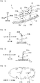
- Figure 1A is a perspective view for explaining a main structure of a vehicular antenna device 1, as an antenna device for a vehicle, according to one embodiment.
- Figure 1B is a rear view for explaining the main structure of the vehicular antenna device 1 according to the embodiment.
- Figure 1C is a front view for explaining the main structure of the vehicular antenna device 1 according to the embodiment.
- Figure 1D is a top view for explaining the main structure of the vehicular antenna device 1 according to the embodiment.
- the vehicular antenna device 1 is mounted on, for example, a roof of a vehicle for use.
- the direction that the vehicle advances (direction of movement) is referred to as “front” or “front direction”
- the opposite direction thereof is referred to as “rear” or “rear direction”
- these directions are referred to as “longitudinal direction” if no distinction is necessary between them.
- the right side of the direction that the vehicle advances is referred to as “right” or “right direction”
- the left side of the direction that the vehicle advances is referred to as “left” or “left direction”
- these directions are referred to as “width direction” if no distinction is necessary between them.
- the direction of the gravitational force of the vehicle is referred to as “bottom” or “lower”, and the opposite direction thereof is referred to as “top” or “upper”.
- the vehicular antenna device 1 of this embodiment includes an antenna base 10 that is attachable to a vehicle and a radio-wave transparent antenna case 11.
- the antenna base 10 is substantially elliptical and is attached such that the center axis line in the longitudinal direction can be parallel to the direction of movement of the vehicle.
- the antenna base 10 includes a substantially elliptical resin base abutted against the part attached to the vehicle, a circuit substrate fixed onto the resin base, and a conductive base shielding electronic parts on the circuit substrate and, at the same time, functioning as a ground conductor for antenna elements 21 and 22, which are described below.
- the conductive base has holes at front and rear positions of a substantially center part, and contact portions in continuity with a feeding point of the circuit substrate are exposed through the holes.
- the antenna case 11 is formed to have a streamline shape having a width and height that decrease toward the front and having sides having a curved surface bowed inward (toward the center axis line in the longitudinal direction) and is fitted onto an outer edge of the antenna base 10.
- the antenna base 10 has a length in the longitudinal direction of about 180 mm and a length in the width direction of about 70 mm.
- the antenna case 11 has a length in the longitudinal direction of about 204 mm, a length in the width direction of about 88 mm, and an upper height of about 64 mm.
- the two antenna elements 21 and 22 are erected in the front-rear direction on the antenna base 10.
- the front antenna elements 21 is dedicated to receive long term evolution (LTE) and the rear antenna element 22 is dedicated to transmit and/or receive LTE, for example.
- LTE long term evolution
- the frequency bands to be used and the application of the transmission and/or reception are not limited thereto.
- the two antenna elements 21 and 22 substantially have an identical basic structure though they have different shapes from each other and also different heights from the conductive base of the antenna base 10. That is, the front antenna element 21 has a proximal end portion 21a that projects in a direction toward the antenna base 10 and two arm portions 211a and 211b that surround a space 210 by extending in a strip shape in directions away from each other from the vicinity of the proximal end portion 21a.
- the proximal end portion 21a is fixed on a plane substantially perpendicular to the antenna base 10.
- space herein refers to an area surrounded by two arm portions (the arm portions 211a and 211b in this embodiment).
- An angle formed by a part facing the antenna base 10 and extending from the proximal end portion 21a of the two arm portions 211a and 211b and the antenna base 10 is an acute angle. In other words, the angle is larger than 0 degrees and smaller than 90 degrees. Because of the strip shape having a larger width than that of a linear shape, two frequency bands of low and high frequencies can be widened.
- strip shape herein refers to a shape having a uniform width and having a larger length of extension than the width.
- the width is equal to substantially 3 mm or larger under constraints that the frequency bands cover the used frequency band of LTE and that the space for installing the two arm portions 211a and 211b cannot be large because they are in the vehicular antenna device, the width is preferably equal to or larger than 5 mm or is more preferably equal to or larger than 7 mm if the above constraints need not be considered.
- the arm portions 211a and 211b may have a width that increases serially or stepwise from the sides close to the proximal end portion 21a toward their tips or may have a uniform width.
- one of the two arm portions 211a and 211b has an area larger than the area of the other one.
- the arm portion 211a has an open end 212a as its tip
- the arm portion 211b has an open end 212b as its tip.
- open end refers to a part where no other conductor or the like exists at a tip of the end.
- the open end 212a of the front arm portion 211a projects toward a direction of a wide region of the space 210, and the open end 212b of the rear arm portion 211b projects to the front and has a distance to ground that decreases toward the front to follow an inner wall of the antenna case 11.
- the open end 212b of the rear arm portion 211b bends down substantially in parallel with the antenna base 10 to load capacitance to ground while securing radiation resistance.
- the two open ends 212a and 212b are disposed closely to form an opening of the space 210 toward a front and lower part.
- the proximal end portion 21a, the arm portions 211a and 211b, and the open ends 212a and 212b are formed by hollowing (or cutting off), for example, one metal plate to a predetermined shape, which is described below.
- the proximal end portion 21a and the two arm portions 211a and 211b are disposed on an identical plane.
- the proximal end portion 21a is mounted and fixed at the above-described contact portion at the front of the substantially center part exposed from the antenna base 10 so as to also function as a feeding part of the two arm portions 211a and 211b.
- the two arm portions 211a and 211b and the open ends 212a and 212b can be operated as an antenna.
- the arm portion 211a and the open end 212a or the arm portion 211b and the open end 212b may be operated as an individual antenna.
- an operating band of 800 MHz to 1100 MHz can be acquired.
- the use in 714 MHz to 894 MHz of an LTE band is enabled by providing a matching circuit and adjusting a circuit constant thereof to a proper value.
- the rear antenna element 22 has a proximal end portion 22a that projects in a direction toward the antenna base 10 and two arm portions 221a and 221b that surround a space 220 by extending in a strip shape in directions away from each other from the vicinity of the proximal end portion 22a.
- the proximal end portion 22a is fixed on a plane substantially perpendicular to the antenna base 10.
- the arm portion 221a has an open end 222a as its tip
- the arm portion 221b has an open end 222b as its tip.
- the open end 222a of the front arm portion 221a projects toward a direction of a wide region of the space 220, and the open end 222b of the rear arm portion 221b projects to the front to follow the inner wall of the antenna case 11.
- a part of the open end 222b of the rear arm portion 221b bends down by an angle of substantially 30 degrees with respect to the antenna base 10 to reduce capacitance to ground while securing radiation resistance.
- the two open ends 222a and 222b are disposed closely to form an opening of the space 220 toward a front and horizontal direction.
- the opening direction of the opening is different from the opening direction of the opening of the space 210 in the front antenna element 21. This is for increasing isolation caused by the proximity of the two antenna elements 21 and 22. This is described below.
- the proximal end portion 22a, the arm portions 221a and 221b, and the open ends 222a and 222b are formed by hollowing (or cutting off), for example, one metal plate to a predetermined shape, which is described below.
- hollowing or cutting off
- the proximal end portion 22a and a part of the two arm portions 221a and 221b and the open ends 222a and 222b are disposed on an identical plane.
- the proximal end portion 22a is mounted and fixed at the above-described contact portion at the rear of the substantially center part exposed from the antenna base 10 so as to also function as a feeding part of the two arm portions 211a and 221b.
- the two arm portions 221a and 221b and the open ends 222a and 222b can be operated as antennas.
- the arm portion 221a and the open end 222a or the arm portion 221b and the open end 222b may be operated as an individual antenna.
- an operating band of 800 MHz to 1100 MHz can be acquired.
- the use in 699 MHz to 894 MHz of an LTE band is enabled by providing a matching circuit and adjusting a circuit constant thereof to a proper value.
- the interval between the arm portions 211a and 211b and the interval between the arm portions 221a and 221b gradationally increase as the distances from the feeding part increase, the intervals may remain the same in a predetermined section from the feeding part and increase after the predetermined section.
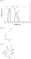
- Figure 3A is a schematic diagram of a first comparative element 31.
- the first comparative element 31 has a quadrangle conductor having a feeding part 30 on one side.
- Figure 3B is a schematic diagram of a second comparative element 32.
- the second comparative element 32 has a strip-shaped conductor having a substantially equal width and having the feeding part 30 at a part thereof.
- the second comparative element 32 is formed by hollowing (or cutting off) the quadrangle conductor of the first comparative element 31 and has a substantially quadrangle outer shape.
- the material of the second comparative element 32 is the same as that of the first comparative element 31, and the second comparative element 32 has an outer shape that is substantially the same as that of the first comparative element 31.
- the strip-shaped conductor of the second comparative element 32 includes two arm portions 321a and 321b extending from the feeding part 30 so as to surround a space 320, and the arm portion 321a has an open end 322a as its tip, and the arm portion 321b has an open end 322b as its tip.
- outer shape refers to a shape acquired by connecting the outermost vertices of an antenna element.
- the shape of a comparative element that is not cut off is the "outer shape”.
- Figure 4 shows an average gain profile against vertically polarized frequencies on a horizontal plane when these comparative elements 31 and 32 are installed on a 1-m circular ground plate.
- Figure 4 has a vertical axis indicating average gain (dBi) and a horizontal axis indicating frequency (MHz).
- dBi average gain
- MHz horizontal axis indicating frequency
- only one frequency band can be used as an antenna with the first comparative element 31. Additionally, the frequency band is displaced from the frequency often used in LTE.
- low and high frequency bands of LTE can be used with the second comparative element 32, but the usable bands may not be always sufficient for LTE applications using a wide frequency band though they are wide to some extent.
- Figure 5A is a schematic diagram of a third comparative element 41.
- the third comparative element 41 has a trapezoidal conductor having the feeding part 30 at one side thereof.
- Figure 5B is a schematic diagram of a fourth comparative element 42.
- the fourth comparative element 42 has a strip-shaped conductor having the feeding part 30 at a part thereof.
- the fourth comparative element 42 is formed by hollowing (or cutting off) the third comparative element 41 to form a substantially trapezoidal outer shape.
- the material of the fourth comparative element 42 is the same as that of the third comparative element 41, and the fourth comparative element 42 has an outer shape that is substantially the same as that of the third comparative element 41.
- the strip-shaped conductor of the fourth comparative element 42 includes two arm portions 421a and 421b extending from the feeding part 30 so as to surround a space 420.
- the arm portions 421a and 421b have open ends 422a and 422b, respectively, as their tips.
- Figure 6 shows an average gain profile against vertically polarized frequencies on a horizontal plane when these comparative elements 41 and 42 are installed on a 1-m circular ground plate.
- Figure 6 has a vertical axis indicating average gain (dBi) and a horizontal axis indicating frequency (MHz).
- dBi average gain
- MHz horizontal axis indicating frequency
- only one frequency band can be used as an antenna with the third comparative element 41.
- low and high frequency bands of LTE can be used with the fourth comparative element 42, but the usable bands may not be sufficient as bands to be used by the LTE frequency bands.
- the antenna gains are lower than those of the first and second comparative elements 31 and 32.
- Figure 7A is a schematic diagram of a fifth comparative element 51.
- the fifth comparative element 51 has an inverted triangular conductor having the feeding part 30 at its vertex part.
- Figure 7B is a schematic diagram of a first modification element 52 of the embodiment.
- the first modification element 52 has a strip-shaped conductor having the feeding part 30 at its vertex part.
- the first modification element 52 is formed by hollowing (or cutting off) the fifth comparative element 51 to form a substantially inverted triangular outer shape.
- the material of the first modification element 52 is the same as that of the fifth comparative element 51, and the first modification element 52 has an outer shape that is substantially the same as that of the fifth comparative element 51.
- the strip-shaped conductor of the first modification element 52 includes two arm portions 521a and 521b extending from the feeding part 30 so as to surround a space 520.
- the arm portion 521a has an open end 522a as its tip
- the arm portion 521b has an open end 522b as its tip.
- An angle formed by a part facing the antenna base and extending away from the feeding part 30 of the strip-shaped conductor and the antenna base is substantially 70 degrees.
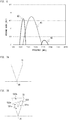
- Figure 8 shows an average gain profile against vertically polarized frequencies on a horizontal plane when the fifth comparative element 51 and the first modification element 52 are installed on a 1-m circular ground plate.
- Figure 8 has a vertical axis indicating average gain (dBi) and a horizontal axis indicating frequency (MHz).
- dBi average gain
- MHz horizontal axis indicating frequency
- two frequency bands can be used as antennas with the fifth comparative element 51 and are displaced from the frequency band that is often used by LTE though the operating band is wide in the high frequency band.
- the first modification element 52 the operating band is narrow in the low frequency band of LTE, and the average gain is small in the high frequency band of LTE.
- Figure 9A is a schematic diagram of a sixth comparative element 61.
- the sixth comparative element 61 has a composite conductor of an inverted triangle and a trapezoid and has the feeding part 30 at its vertex part.
- An angle formed by a part facing the antenna base and extending away from the feeding part 30 of the conductor and the antenna base is substantially 25 degrees.
- Figure 9B is a schematic diagram of a second modification element 62 of the embodiment.
- the second modification element 62 has a strip-shaped conductor having the feeding part 30 at its vertex part.
- the second modification element 62 is formed by hollowing (or cutting off) the sixth comparative element 61 to form an outer shape combining a substantially inverted-triangular shape and a substantially trapezoidal shape.
- the material of the second modification element 62 is the same as that of the sixth comparative element 61, and the second modification element 62 has an outer shape that is substantially the same as that of the sixth comparative element 61.
- the strip-shaped conductor of the second modification element 62 has two arm portions 621a and 621b extending in a strip shape in directions away from each other from the feeding part 30 so as to surround a space 620.
- the distances between the arm portions 621a and 621b and the antenna base 10 also gradually increase as the extension increases.
- the arm portions 621a and 621b have open ends 622a and 622b, respectively, as their tips, and the part where they face is an opening of the space 620.
- An angle formed by a part facing the antenna base and extending away from the feeding part 30 of the second modification element 62 and the antenna base is substantially 25 degrees.
- Figure 10 shows an average gain profile against vertically polarized frequencies on a horizontal plane when the sixth comparative element 61 and the second modification element 62 are installed on a 1-m circular ground plate.
- Figure 10 has a vertical axis indicating average gain (dBi) and a horizontal axis indicating frequency (MHz).
- dBi average gain
- MHz horizontal axis indicating frequency
- the frequency band is as wide as about 900 MHz to about 3700 MHz.
- the sixth comparative element 61 cannot be used at a frequency lower than about 800 MHz of LTE and higher than 3700 MHz.
- the frequency that can be used with a certain or higher antenna gain can extend to a lower frequency as the lower frequency band and can extend to a higher frequency as the high frequency band.
- the inductance L is small in the high frequency band and the usable frequency is high.
- the second modification element 62 operating as described above is adopted as the front antenna element 21.
- the frequency usable with a certain or higher antenna gain can be lower in the low frequency band and can be higher in the high frequency band.
- the width of the arm portions 621a and 621b may be changed, or a part of the open end 622b may be bent down as shown in Figures 1 and 2 . The bending does not lower the antenna gain if the area is equal.
- Figure 11A is a schematic diagram of a seventh comparative element 71.
- the seventh comparative element 71 has a composite conductor of an inverted triangle and a trapezoid and has the feeding part 30 at its vertex part.
- An angle formed by a part facing the antenna base and extending away from the feeding part 30 of the conductor and the antenna base is substantially 35 degrees.
- Figure 11B is a schematic diagram of a third modification element 72 of the embodiment.
- the third modification element 72 has a strip-shaped conductor having the feeding part 30 at its vertex part.
- the third modification element 72 is formed by hollowing (or cutting off) the seventh comparative element 71 and has an outer shape combining a substantially inverted-triangular shape and a substantially trapezoidal shape.
- the size of the outer shape is substantially equal to that of the seventh comparative element 71 and has two arm portions 721a and 721b extending in a strip shape in directions away from each other from the feeding part 30 so as to surround a space 720.
- the distances between the arm portions 721a and 721b and the antenna base 10 also gradually increase as the extension increases.
- the arm portion 721a has an open end 722a as its tip, and the arm portion 721b has an open end 722b as its tip.
- a gap between the open end 722a and the open end 722b is an opening of the space 720.
- An angle formed by a part facing the antenna base and extending away from the feeding part 30 of the third modification element 72 and the antenna base is substantially 35 degrees.
- Figure 12 shows an average gain profile against vertically polarized frequencies on a horizontal plane when the seventh comparative elements 71 and the third modification element 72 are installed on a 1-m circular ground plate.
- Figure 12 has a vertical axis indicating average gain (dBi) and a horizontal axis indicating frequency (MHz).
- dBi average gain
- MHz horizontal axis indicating frequency
- the usable frequency is a wide frequency of about 900 MHz to about 3600 MHz. However, it cannot be used at frequencies lower than about 800 MHz of LTE.
- the third modification element 72 the usable frequency extends to a lower frequency in the low frequency band.
- the high frequency band is displaced to the low frequency band by about 600 MHz.
- the arm portion 721a is longer than the arm portion 621a.
- the arm portion 721a is adopted as the rear antenna element 22 by adjusting the length of the arm portion 721a to support a desired frequency band.
- the strip-shaped conductors of the second modification element 62 and the third modification element 72 have, for example, the two arm portions 211a and 211b and the open ends 212a and 212b caused to extend in directions away from each other from the feeding part 30 and also to be away from the conductive base of the antenna base 10.
- the arm portion 211a has a lower inductance L than that of a planer conductor having the same material and outer shape
- the arm portion 211b has a higher inductance L than that of the planer conductor having the same material and outer shape, so that two frequency bands of a low frequency band and a high frequency band of, for example, LTE are generated by the one antenna element.
- the capacitance to ground can be increased, and the resonance frequency can be reduced. Since a part or all of the open ends 322a, 322b, 422a, 422b, 522a, 522b, 622a, 622b, 722a, and 722b may be properly bent down in accordance with the shape of the inner wall of the antenna case 11, extended variations of the design can be achieved.
- planer conductors of the first comparative element 31, the third comparative element 41, the fifth comparative element 51, the sixth comparative element 61 and the seventh comparative element 71 are hollowed (or cut off) to acquire the second comparative element 32, the fourth comparative element 42, the first modification element 52, the second modification element 62 and the third modification element 72 each having a strip-shaped conductor surrounding a predetermined space so that, for example, the processes for manufacturing the modification elements 52, 62, and 72 can be simplified.
- the isolation between the elements is often problematic.
- the interval between the strip-shaped conductors may have a length that suppresses interference of used frequencies, the isolation can also be increased by properly adjusting the opening directions of the openings of the spaces surrounded by the strip-shaped conductors as shown in Figure 13A to Figure 13D .
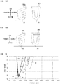
- Figure 13A shows a first example in which the direction of an opening of a front antenna element 81a is a front lower direction, and the direction of an opening of a rear antenna element 81b is a front and horizontal direction.
- Figure 13B shows a second example in which the direction of an opening of a front antenna element 82a is a direction toward a front and lower direction, and the direction of an opening of a rear antenna element 82b is a rear and horizontal direction.
- Figure 13C shows a third example in which the direction of an opening of a front antenna element 83a is a rear and upper direction, and the direction of an opening of a rear antenna element 83b is a front and horizontal direction.
- Figure 13D shows a fourth example in which the direction of an opening of a front antenna element 84a is a rear and upper direction, and the direction of an opening of a rear antenna element 84b is a rear and horizontal direction.
- Figure 14 is an isolation characteristic diagram of the first to fourth examples.
- Figure 14 has a vertical axis indicating isolation (dB) and a horizontal axis indicating frequency (MHz).
- a short dashed line 81 represents an isolation in the case of the first example
- a solid line 82 represents an isolation in the case of the second example
- a long dashed line 83 represents an isolation in the case of the third example
- an alternate long and short dashed line represents an isolation in the case of the fourth example.
- the isolation of the second example represented by the solid line 82 has the best characteristic in the low frequency band (around 900 MHz).
- the widths of the arm portions 211a, 211b, 221a and 221b may be the narrowest at the proximal end portions 21a and 22a and may increase in a tapered shape as the distances from the proximal end portions 21a and 22a increase.
- an incision may be provided at a part of the arm portions 211a, 211b, 221a, 221b and so on and the open ends 212a, 212b, 222a, and 222b.
- the antenna elements 21 and 22 can have a shape other than the shape examples described according to this embodiment.
- the antenna elements 21 and 22 may have, for example, a substantial V shape, a substantial U shape, a substantial C shape, or a substantial G shape.
- each of the two antenna elements 21 and 22 since each of the two antenna elements 21 and 22 according to this embodiment includes two arm portions having different shapes (at least one of its outer shape and length) as one element, the two antenna elements 21 and 22 can be operated in two of high and low frequency bands of, for example, LTE.
- the two antenna elements 21 and 22 have an average gain of -6 dBi or lower around 1500 MHz to around 2000 MHz.
- a significantly large isolation between two frequencies in the low and high frequency bands of LTE is acquired around 1500 MHz.
- the interference between the GNSS antenna and the two antenna elements 21 and 22 can be avoided.
- the cases have been described where the angle formed by the part facing the antenna base 10 and extending from the proximal end portion 21a of the two arm portions 211a and 211b and the antenna base 10 is an acute angle.
- the influence of the difference in angle given to the antenna characteristic is described below.
- first modification element 52 changes in antenna characteristic (such as frequency band) caused when the angle is variously changed are described by using the above-described first modification element 52, second modification element 62, third modification element 72 and first comparative element 31 to seventh comparative element 71.
- first modification element 52 changes in antenna characteristic caused when the angle is variously changed are described by using the above-described first modification element 52, second modification element 62, third modification element 72 and first comparative element 31 to seventh comparative element 71.
- first modification elements and the comparative elements are the same.
- the angle formed by the part facing the antenna base 10 and extending from the proximal end portion of the two arm portions 211a and 211b and the antenna base 10 is referred to as "extension angle" for convenience of description.
- the extension angle of the first comparative element 31 is 0 degrees
- the extension angle of the seventh comparative element 71 is substantially 35 degrees
- the extension angle of the fifth comparative element 51 is substantially 70 degrees.
- the frequency band (hereinafter, "operating band") with which the first comparative element 31 can operate as an antenna is about 1000 MHz to about 2300 MHz as shown in Figure 4
- the operating band of the seventh comparative element 71 is about 900 MHz to about 3600 MHz as shown in Figure 12 .
- the extension angle increases from 0 degrees
- the operating band is widened. This is due to the radiation efficiency improved when the extension angle exceeds 0 degrees because the extending part operates as a travelling-wave antenna.
- the operating band of the fifth comparative element 51 is about 800 MHz to 1300 MHz on the low frequency side of LTE and is about 2500 MHz to 4000 MHz on the high frequency side of LTE. Comparing with the seventh comparative element 71 with an extension angle of substantially 35 degrees, the larger extension angle of the fifth comparative element 51 improves the radiation efficiency on the high frequency side, which widens the operating band on the high frequency side while narrowing the operating band on the low frequency side.
- the operating band is widened when the extension angle is substantially 35 degrees, compared with the case where the extension angle is 0 degrees.
- the operating band is widened when the extension angle is substantially 70 degrees compared with the case where the extension angle is 0 degrees but is narrowed compared with the case where the extension angle is substantially 35 degrees.
- the extension angle of the second comparative element 32 is 0 degrees
- the extension angle of the third modification element 72 is substantially 35 degrees
- the extension angle of the first modification element 52 is substantially 70 degrees.
- the operating band of the second comparative element 32 is about 800 MHz to about 1200 MHz on the low frequency side of LTE and is about 1800 MHz to about 2500 MHz on the high frequency side of LTE, as shown in Figure 4 .
- the operating band of the third modification element 72 is about 750 MHz to about 1300 MHz on the low frequency side of LTE and is about 1800 MHz to about 3300 MHz on the high frequency side of LTE, as shown in Figure 12 . In this way, when the extension angle exceeds 0 degrees, the operating band is widened.
- the operating band of the first modification element 52 is about 750 MHz to about 1200 MHz on the low frequency side of LTE and is about 2300 MHz to about 2500 MHz on the high frequency side of LTE. While the extension angle of the first modification element 52 is larger than that of the third modification element 72, the operating band is narrowed.
- the operating band is widened when the extension angle is substantially 35 degrees compared with the case where the extension angle is 0 degrees, the operating band is narrowed when the extension angle is substantially 70 degrees compared with the case where the extension angle is substantially 35 degrees.
- an influence of an extension angle of an element with no arm portion given to an antenna characteristic is described by comparing the third comparative element 41 and the sixth comparative element 61.
- the extension angle of the third comparative element 41 is 0 degrees
- the extension angle of the sixth comparative element 61 is substantially 25 degrees.
- the operating band of the third comparative element 41 is about 1000 MHz to about 2500 MHz
- the operating band of the sixth comparative element 61 is about 900 MHz to about 3700 MHz. In this way, when the extension angle exceeds 0 degrees, the operating band is widened.
- the extension angle of the fourth comparative element 42 is 0 degrees, and the extension angle of the second modification element 62 is substantially 25 degrees.
- the operating band of the fourth comparative element 42 is about 1000 MHz to about 1200 MHz on the low frequency side of LTE and is about 2400 MHz to about 2700 MHz on the high frequency side of LTE.
- the operating band of the second modification element 62 is about 900 MHz to about 1400 MHz on the low frequency side of LTE and is about 2300 MHz to about 3800 MHz on the high frequency side of LTE.
- the extension angle exceeds 0 degrees, the radiation efficiency of the high frequency side of LTE is improved, and the operating band is widened. Also, since the radiation efficiency of the second modification element 62 is improved more than the fourth comparative element 42, the gain on the high frequency side of LTE improves.
- the operating band can be widened when the extension angle is an acute angle greater than 0 degrees.
- the extension angles are substantially 25 degrees, substantially 35 degrees and substantially 70 degrees
- the experiment by the present inventor et al. shows that the extension angle may be an angle other than those described above, such as substantially 15 degrees to substantially 25 degrees, substantially 30 degrees, or substantially 35 degrees to substantially 65 degrees, and is preferably substantially 15 degrees to substantially 45 degrees, in accordance with a desired operating band.
- the two antenna elements 21 and 22 have different shapes from each other and have different heights from the conductive base of the antenna base 10, embodiments of the present invention are not limited thereto.
- the two antenna elements may have an identical shape in accordance with the height and shape of the case accommodating the two antenna elements.
- extension angles of the two arm portions of each of the two antenna elements 21 and 22 are substantially equal, embodiments of the present invention are not limited thereto.
- the extension angles of two arm portions of at least one of the two antenna elements 21 and 22 may be different.
- embodiments of the present invention are not limited thereto.
- only the extension angles may be adjusted, or the extension angles and the lengths of the elements may be adjusted.
Landscapes
- Engineering & Computer Science (AREA)
- Remote Sensing (AREA)
- Details Of Aerials (AREA)
- Variable-Direction Aerials And Aerial Arrays (AREA)
- Support Of Aerials (AREA)
Abstract
Description
- The present invention relates to an antenna device for a vehicle that can be used at a plurality of frequency bands.
- In recent years, the variety of functions of electronic communication devices mounted in vehicles has been increased, and, correspondingly with that, there has been an increased demand for an antenna device for a vehicle that can alone use a plurality of frequency bands. As an example of a conventional antenna device for a vehicle that meets such a demand, there is a two-frequency antenna disclosed in Patent Literature 1. The two-frequency antenna has a planer first element on a front surface of an insulative substrate erected on a ground (ground plane), a through hole in vicinity of a feeding part, a planer second element at a position which does not overlap with the first element of a back surface of the substrate, and a feeding line in continuity with the through hole.
- Because the two-frequency antenna does not need a coil part because inductance caused in the two-frequency antenna having a low profile for mounting in a vehicle is compensated by the feeding line and because of the configuration having the two elements and the feeding line formed in a printed pattern on one substrate, an antenna device for a vehicle is advantageously acquired easily and inexpensively.
- Patent Literature 1:
Japanese Patent Laid-Open No. 2013-85308 - In the above described two-frequency antenna, the two planer elements are disposed on the front surface and the back surface of one substrate such that the two planer elements do not overlap with each other, and one element transmits or receives one frequency band. Each of the elements has an area dependent on the size of the substrate. Therefore, in a case where the two-frequency antenna is applied to an antenna device for a vehicle, the antenna gain cannot be increased relatively in a low frequency band because the size of the substrate cannot be increased.
- It is an object of the present invention to provide an antenna device for a vehicle which is small but has two frequency bands of a low frequency band and a frequency band higher than the low frequency band.
- An antenna device for a vehicle according to one aspect of the present invention includes an antenna base, and an antenna element erected on the antenna base. The antenna element includes a proximal end portion fixed on a plane substantially perpendicular to the antenna base and two arm portions extending in directions away from each other from the proximal end portion, and an inductance of at least one of the two arm portions is larger than an inductance of a planer conductor having a same material and a substantially same outer shape.
- According to the present invention, an antenna device for a vehicle can be provided which is small but has two frequency bands of a low frequency band and a frequency band higher than the low frequency band.
-
- [
Figure 1A] Figure 1A is a perspective view for explaining a main structure of a vehicular antenna device 1 according to one embodiment. - [
Figure 1B] Figure 1B is a rear view for explaining the main structure of the vehicular antenna device 1 according to the embodiment. - [
Figure 1C] Figure 1C is a front view for explaining the main structure of the vehicular antenna device 1 according to the embodiment. - [
Figure 1D] Figure 1D is a top view for explaining the main structure of the vehicular antenna device 1 according to the embodiment. - [
Figure 2A] Figure 2A is an explanatory diagram of an internal structure of the vehicular antenna device viewed from a right side. - [
Figure 2B] Figure 2B is an explanatory diagram of the internal structure of the vehicular antenna device viewed from a left side. - [
Figure 3A] Figure 3A is a schematic diagram of a first comparative element. - [
Figure 3B] Figure 3B is a schematic diagram of a second comparative element. - [
Figure 4] Figure 4 shows an average gain profile against vertically polarized frequencies on a horizontal plane when the first and second comparative elements are installed on a 1-m circular ground plate. - [
Figure 5A] Figure 5A is a schematic diagram of a third comparative element. - [
Figure 5B] Figure 5B is a schematic diagram of a fourth comparative element. - [
Figure 6] Figure 6 shows an average gain profile against vertically polarized frequencies on a horizontal plane when the third and fourth comparative elements are installed on a 1-m circular ground plate. - [
Figure 7A] Figure 7A is a schematic diagram of a fifth comparative element. - [
Figure 7B] Figure 7B is a schematic diagram of a first modification element of the embodiment. - [
Figure 8] Figure 8 shows an average gain profile against vertically polarized frequencies on a horizontal plane when the fifth comparative element and the first modification element of the embodiment are installed on a 1-m circular ground plate. - [
Figure 9A] Figure 9A is a schematic diagram of a sixth comparative element. - [
Figure 9B] Figure 9B is a schematic diagram of a second modification element of the embodiment. - [
Figure 10] Figure 10 shows an average gain profile against vertically polarized frequencies on a horizontal plane when the sixth comparative element and the second modification element of the embodiment are installed on a 1-m circular ground plate. - [
Figure 11A] Figure 11A is a schematic diagram of a seventh comparative element. - [
Figure 11B] Figure 11B is a schematic diagram of a third modification element of the embodiment. - [
Figure 12] Figure 12 shows an average gain profile against vertically polarized frequencies on a horizontal plane when the seventh comparative element and the third modification element of the embodiment are installed on a 1-m circular ground plate. - [
Figure 13A] Figure 13A is a schematic diagram of a variation of arrangement of two antenna elements. - [
Figure 13B] Figure 13B is a schematic diagram of a variation of arrangement of two antenna elements. - [
Figure 13C] Figure 13C is a schematic diagram of a variation of arrangement of two antenna elements. - [
Figure 13D] Figure 13D is a schematic diagram of a variation of arrangement of two antenna elements. - [
Figure 14] Figure 14 shows isolation curves with the arrangement examples inFigures 13A to 13D . - An exemplary embodiment of the present invention is described below with reference to drawings.
-
Figure 1A is a perspective view for explaining a main structure of a vehicular antenna device 1, as an antenna device for a vehicle, according to one embodiment.Figure 1B is a rear view for explaining the main structure of the vehicular antenna device 1 according to the embodiment.Figure 1C is a front view for explaining the main structure of the vehicular antenna device 1 according to the embodiment.Figure 1D is a top view for explaining the main structure of the vehicular antenna device 1 according to the embodiment. - The vehicular antenna device 1 is mounted on, for example, a roof of a vehicle for use. In the attached drawings, the direction that the vehicle advances (direction of movement) is referred to as "front" or "front direction", the opposite direction thereof is referred to as "rear" or "rear direction", and these directions are referred to as "longitudinal direction" if no distinction is necessary between them. The right side of the direction that the vehicle advances is referred to as "right" or "right direction", the left side of the direction that the vehicle advances is referred to as "left" or "left direction", and these directions are referred to as "width direction" if no distinction is necessary between them. The direction of the gravitational force of the vehicle is referred to as "bottom" or "lower", and the opposite direction thereof is referred to as "top" or "upper".
- The vehicular antenna device 1 of this embodiment includes an
antenna base 10 that is attachable to a vehicle and a radio-wavetransparent antenna case 11. - The
antenna base 10 is substantially elliptical and is attached such that the center axis line in the longitudinal direction can be parallel to the direction of movement of the vehicle. Theantenna base 10 includes a substantially elliptical resin base abutted against the part attached to the vehicle, a circuit substrate fixed onto the resin base, and a conductive base shielding electronic parts on the circuit substrate and, at the same time, functioning as a ground conductor forantenna elements - The
antenna case 11 is formed to have a streamline shape having a width and height that decrease toward the front and having sides having a curved surface bowed inward (toward the center axis line in the longitudinal direction) and is fitted onto an outer edge of theantenna base 10. Theantenna base 10 has a length in the longitudinal direction of about 180 mm and a length in the width direction of about 70 mm. Theantenna case 11 has a length in the longitudinal direction of about 204 mm, a length in the width direction of about 88 mm, and an upper height of about 64 mm. - The two
antenna elements antenna base 10. Although, according to this embodiment, thefront antenna elements 21 is dedicated to receive long term evolution (LTE) and therear antenna element 22 is dedicated to transmit and/or receive LTE, for example. It is noted that the frequency bands to be used and the application of the transmission and/or reception are not limited thereto. - The two
antenna elements antenna base 10. That is, thefront antenna element 21 has aproximal end portion 21a that projects in a direction toward theantenna base 10 and twoarm portions space 210 by extending in a strip shape in directions away from each other from the vicinity of theproximal end portion 21a. Theproximal end portion 21a is fixed on a plane substantially perpendicular to theantenna base 10. The term "space" herein refers to an area surrounded by two arm portions (thearm portions - An angle formed by a part facing the
antenna base 10 and extending from theproximal end portion 21a of the twoarm portions antenna base 10 is an acute angle. In other words, the angle is larger than 0 degrees and smaller than 90 degrees. Because of the strip shape having a larger width than that of a linear shape, two frequency bands of low and high frequencies can be widened. - The term "strip shape" herein refers to a shape having a uniform width and having a larger length of extension than the width. Although, according to this embodiment, the width is equal to substantially 3 mm or larger under constraints that the frequency bands cover the used frequency band of LTE and that the space for installing the two
arm portions - The
arm portions proximal end portion 21a toward their tips or may have a uniform width. - Viewing a virtual line in a vertical direction from the
proximal end portion 21a as a boundary line, one of the twoarm portions arm portion 211a has anopen end 212a as its tip, and thearm portion 211b has anopen end 212b as its tip. - The term "open end" herein refers to a part where no other conductor or the like exists at a tip of the end.
- The
open end 212a of thefront arm portion 211a projects toward a direction of a wide region of thespace 210, and theopen end 212b of therear arm portion 211b projects to the front and has a distance to ground that decreases toward the front to follow an inner wall of theantenna case 11. Theopen end 212b of therear arm portion 211b bends down substantially in parallel with theantenna base 10 to load capacitance to ground while securing radiation resistance. The twoopen ends space 210 toward a front and lower part. - The
proximal end portion 21a, thearm portions proximal end portion 21a and the twoarm portions - The
proximal end portion 21a is mounted and fixed at the above-described contact portion at the front of the substantially center part exposed from theantenna base 10 so as to also function as a feeding part of the twoarm portions arm portions arm portion 211a and theopen end 212a or thearm portion 211b and theopen end 212b may be operated as an individual antenna. - In this way, since the two
arm portions - Since the two
arm portions - The
rear antenna element 22 has aproximal end portion 22a that projects in a direction toward theantenna base 10 and twoarm portions space 220 by extending in a strip shape in directions away from each other from the vicinity of theproximal end portion 22a. Theproximal end portion 22a is fixed on a plane substantially perpendicular to theantenna base 10. Thearm portion 221a has anopen end 222a as its tip, and thearm portion 221b has anopen end 222b as its tip. - The
open end 222a of thefront arm portion 221a projects toward a direction of a wide region of thespace 220, and theopen end 222b of therear arm portion 221b projects to the front to follow the inner wall of theantenna case 11. A part of theopen end 222b of therear arm portion 221b bends down by an angle of substantially 30 degrees with respect to theantenna base 10 to reduce capacitance to ground while securing radiation resistance. The twoopen ends space 220 toward a front and horizontal direction. The opening direction of the opening is different from the opening direction of the opening of thespace 210 in thefront antenna element 21. This is for increasing isolation caused by the proximity of the twoantenna elements - The
proximal end portion 22a, thearm portions proximal end portion 22a and a part of the twoarm portions - The
proximal end portion 22a is mounted and fixed at the above-described contact portion at the rear of the substantially center part exposed from theantenna base 10 so as to also function as a feeding part of the twoarm portions arm portions arm portion 221a and theopen end 222a or thearm portion 221b and theopen end 222b may be operated as an individual antenna. - In this way, since the two
arm portions - Since the two
arm portions - Although, in the example shown in
Figures 1A to 1D andFigures 2A and 2B , the interval between thearm portions arm portions - In order to describe reasons why the
antenna elements Figures 1A to 1D andFigures 2A and 2B are adopted, experiment results regarding antenna characteristics of several comparative elements and modification elements of this embodiment that operate in low and high frequency bands of LTE are described first. -
Figure 3A is a schematic diagram of a firstcomparative element 31. The firstcomparative element 31 has a quadrangle conductor having a feedingpart 30 on one side.Figure 3B is a schematic diagram of a secondcomparative element 32. The secondcomparative element 32 has a strip-shaped conductor having a substantially equal width and having the feedingpart 30 at a part thereof. The secondcomparative element 32 is formed by hollowing (or cutting off) the quadrangle conductor of the firstcomparative element 31 and has a substantially quadrangle outer shape. In other words, the material of the secondcomparative element 32 is the same as that of the firstcomparative element 31, and the secondcomparative element 32 has an outer shape that is substantially the same as that of the firstcomparative element 31. The strip-shaped conductor of the secondcomparative element 32 includes twoarm portions part 30 so as to surround aspace 320, and thearm portion 321a has anopen end 322a as its tip, and thearm portion 321b has anopen end 322b as its tip. - The term "outer shape" herein refers to a shape acquired by connecting the outermost vertices of an antenna element. For example, the shape of a comparative element that is not cut off is the "outer shape".
-
Figure 4 shows an average gain profile against vertically polarized frequencies on a horizontal plane when thesecomparative elements Figure 4 has a vertical axis indicating average gain (dBi) and a horizontal axis indicating frequency (MHz). As shown inFigure 4 , only one frequency band can be used as an antenna with the firstcomparative element 31. Additionally, the frequency band is displaced from the frequency often used in LTE. On the other hand, low and high frequency bands of LTE can be used with the secondcomparative element 32, but the usable bands may not be always sufficient for LTE applications using a wide frequency band though they are wide to some extent. -
Figure 5A is a schematic diagram of a thirdcomparative element 41. The thirdcomparative element 41 has a trapezoidal conductor having the feedingpart 30 at one side thereof.Figure 5B is a schematic diagram of a fourthcomparative element 42. The fourthcomparative element 42 has a strip-shaped conductor having the feedingpart 30 at a part thereof. The fourthcomparative element 42 is formed by hollowing (or cutting off) the thirdcomparative element 41 to form a substantially trapezoidal outer shape. In other words, the material of the fourthcomparative element 42 is the same as that of the thirdcomparative element 41, and the fourthcomparative element 42 has an outer shape that is substantially the same as that of the thirdcomparative element 41. The strip-shaped conductor of the fourthcomparative element 42 includes twoarm portions part 30 so as to surround aspace 420. Thearm portions open ends -
Figure 6 shows an average gain profile against vertically polarized frequencies on a horizontal plane when thesecomparative elements Figure 6 has a vertical axis indicating average gain (dBi) and a horizontal axis indicating frequency (MHz). As shown inFigure 6 , only one frequency band can be used as an antenna with the thirdcomparative element 41. On the other hand, low and high frequency bands of LTE can be used with the fourthcomparative element 42, but the usable bands may not be sufficient as bands to be used by the LTE frequency bands. Additionally, the antenna gains are lower than those of the first and secondcomparative elements -
Figure 7A is a schematic diagram of a fifthcomparative element 51. The fifthcomparative element 51 has an inverted triangular conductor having the feedingpart 30 at its vertex part.Figure 7B is a schematic diagram of afirst modification element 52 of the embodiment. Thefirst modification element 52 has a strip-shaped conductor having the feedingpart 30 at its vertex part. Thefirst modification element 52 is formed by hollowing (or cutting off) the fifthcomparative element 51 to form a substantially inverted triangular outer shape. In other words, the material of thefirst modification element 52 is the same as that of the fifthcomparative element 51, and thefirst modification element 52 has an outer shape that is substantially the same as that of the fifthcomparative element 51. The strip-shaped conductor of thefirst modification element 52 includes twoarm portions part 30 so as to surround aspace 520. Thearm portion 521a has anopen end 522a as its tip, and thearm portion 521b has anopen end 522b as its tip. An angle formed by a part facing the antenna base and extending away from the feedingpart 30 of the strip-shaped conductor and the antenna base is substantially 70 degrees. -
Figure 8 shows an average gain profile against vertically polarized frequencies on a horizontal plane when the fifthcomparative element 51 and thefirst modification element 52 are installed on a 1-m circular ground plate.Figure 8 has a vertical axis indicating average gain (dBi) and a horizontal axis indicating frequency (MHz). As shown inFigure 8 , two frequency bands can be used as antennas with the fifthcomparative element 51 and are displaced from the frequency band that is often used by LTE though the operating band is wide in the high frequency band. On the other hand, with thefirst modification element 52, the operating band is narrow in the low frequency band of LTE, and the average gain is small in the high frequency band of LTE. -
Figure 9A is a schematic diagram of a sixthcomparative element 61. The sixthcomparative element 61 has a composite conductor of an inverted triangle and a trapezoid and has the feedingpart 30 at its vertex part. An angle formed by a part facing the antenna base and extending away from the feedingpart 30 of the conductor and the antenna base is substantially 25 degrees.Figure 9B is a schematic diagram of asecond modification element 62 of the embodiment. Thesecond modification element 62 has a strip-shaped conductor having the feedingpart 30 at its vertex part. Thesecond modification element 62 is formed by hollowing (or cutting off) the sixthcomparative element 61 to form an outer shape combining a substantially inverted-triangular shape and a substantially trapezoidal shape. The material of thesecond modification element 62 is the same as that of the sixthcomparative element 61, and thesecond modification element 62 has an outer shape that is substantially the same as that of the sixthcomparative element 61. The strip-shaped conductor of thesecond modification element 62 has twoarm portions part 30 so as to surround aspace 620. The distances between thearm portions antenna base 10 also gradually increase as the extension increases. Thearm portions open ends space 620. An angle formed by a part facing the antenna base and extending away from the feedingpart 30 of thesecond modification element 62 and the antenna base is substantially 25 degrees. -
Figure 10 shows an average gain profile against vertically polarized frequencies on a horizontal plane when the sixthcomparative element 61 and thesecond modification element 62 are installed on a 1-m circular ground plate.Figure 10 has a vertical axis indicating average gain (dBi) and a horizontal axis indicating frequency (MHz). As shown inFigure 10 , although one frequency band can be used as an antenna with the sixthcomparative element 61, the frequency band is as wide as about 900 MHz to about 3700 MHz. However, the sixthcomparative element 61 cannot be used at a frequency lower than about 800 MHz of LTE and higher than 3700 MHz. On the other hand, with thesecond modification element 62, the frequency that can be used with a certain or higher antenna gain can extend to a lower frequency as the lower frequency band and can extend to a higher frequency as the high frequency band. - This may be because the
arm portions antenna base 10 to thearm portions - According to this embodiment, the
second modification element 62 operating as described above is adopted as thefront antenna element 21. Thus, compared with, for example, the sixthcomparative element 61, the frequency usable with a certain or higher antenna gain can be lower in the low frequency band and can be higher in the high frequency band. In a case where thesecond modification element 62 is used as theantenna element 21, the width of thearm portions open end 622b may be bent down as shown inFigures 1 and2 . The bending does not lower the antenna gain if the area is equal. -
Figure 11A is a schematic diagram of a seventhcomparative element 71. The seventhcomparative element 71 has a composite conductor of an inverted triangle and a trapezoid and has the feedingpart 30 at its vertex part. An angle formed by a part facing the antenna base and extending away from the feedingpart 30 of the conductor and the antenna base is substantially 35 degrees.Figure 11B is a schematic diagram of athird modification element 72 of the embodiment. Thethird modification element 72 has a strip-shaped conductor having the feedingpart 30 at its vertex part. Thethird modification element 72 is formed by hollowing (or cutting off) the seventhcomparative element 71 and has an outer shape combining a substantially inverted-triangular shape and a substantially trapezoidal shape. The size of the outer shape is substantially equal to that of the seventhcomparative element 71 and has twoarm portions part 30 so as to surround aspace 720. The distances between thearm portions antenna base 10 also gradually increase as the extension increases. Thearm portion 721a has anopen end 722a as its tip, and thearm portion 721b has anopen end 722b as its tip. A gap between theopen end 722a and theopen end 722b is an opening of thespace 720. An angle formed by a part facing the antenna base and extending away from the feedingpart 30 of thethird modification element 72 and the antenna base is substantially 35 degrees. -
Figure 12 shows an average gain profile against vertically polarized frequencies on a horizontal plane when the seventhcomparative elements 71 and thethird modification element 72 are installed on a 1-m circular ground plate.Figure 12 has a vertical axis indicating average gain (dBi) and a horizontal axis indicating frequency (MHz). As shown inFigure 12 , with the seventhcomparative element 71, although one frequency band can be used as an antenna, the usable frequency is a wide frequency of about 900 MHz to about 3600 MHz. However, it cannot be used at frequencies lower than about 800 MHz of LTE. On the other hand, with thethird modification element 72, the usable frequency extends to a lower frequency in the low frequency band. However, compared with the above-describedsecond modification element 62, the high frequency band is displaced to the low frequency band by about 600 MHz. This is because thearm portion 721a is longer than thearm portion 621a. Accordingly, in this embodiment, thearm portion 721a is adopted as therear antenna element 22 by adjusting the length of thearm portion 721a to support a desired frequency band. - In this way, according to this embodiment, the strip-shaped conductors of the
second modification element 62 and thethird modification element 72 have, for example, the twoarm portions part 30 and also to be away from the conductive base of theantenna base 10. Thus, thearm portion 211a has a lower inductance L than that of a planer conductor having the same material and outer shape, and thearm portion 211b has a higher inductance L than that of the planer conductor having the same material and outer shape, so that two frequency bands of a low frequency band and a high frequency band of, for example, LTE are generated by the one antenna element. - By increasing the area of the arm portions (including the open ends 212a and 212b), the capacitance to ground can be increased, and the resonance frequency can be reduced. Since a part or all of the open ends 322a, 322b, 422a, 422b, 522a, 522b, 622a, 622b, 722a, and 722b may be properly bent down in accordance with the shape of the inner wall of the
antenna case 11, extended variations of the design can be achieved. - Since the planer conductors of the first
comparative element 31, the thirdcomparative element 41, the fifthcomparative element 51, the sixthcomparative element 61 and the seventhcomparative element 71 are hollowed (or cut off) to acquire the secondcomparative element 32, the fourthcomparative element 42, thefirst modification element 52, thesecond modification element 62 and thethird modification element 72 each having a strip-shaped conductor surrounding a predetermined space so that, for example, the processes for manufacturing themodification elements - According to this embodiment, since the two
antenna elements Figure 13A to Figure 13D . -
Figure 13A shows a first example in which the direction of an opening of afront antenna element 81a is a front lower direction, and the direction of an opening of arear antenna element 81b is a front and horizontal direction.Figure 13B shows a second example in which the direction of an opening of afront antenna element 82a is a direction toward a front and lower direction, and the direction of an opening of arear antenna element 82b is a rear and horizontal direction.Figure 13C shows a third example in which the direction of an opening of afront antenna element 83a is a rear and upper direction, and the direction of an opening of arear antenna element 83b is a front and horizontal direction.Figure 13D shows a fourth example in which the direction of an opening of afront antenna element 84a is a rear and upper direction, and the direction of an opening of arear antenna element 84b is a rear and horizontal direction. - The directions of openings in all of the examples do not agree with the directions of the openings of the other elements.
-
Figure 14 is an isolation characteristic diagram of the first to fourth examples.Figure 14 has a vertical axis indicating isolation (dB) and a horizontal axis indicating frequency (MHz). InFigure 14 , a short dashedline 81 represents an isolation in the case of the first example, asolid line 82 represents an isolation in the case of the second example, a long dashedline 83 represents an isolation in the case of the third example, and an alternate long and short dashed line represents an isolation in the case of the fourth example. - In this way, although, with any of the combinations, a sufficient isolation is obtained in either of the low frequency band and the high frequency band of LTE, the isolation of the second example represented by the
solid line 82 has the best characteristic in the low frequency band (around 900 MHz). - The widths of the
arm portions proximal end portions proximal end portions arm portions - The
antenna elements antenna elements - As described above, since each of the two
antenna elements antenna elements Figure 10 andFigure 12 , the twoantenna elements Figure 14 , a significantly large isolation between two frequencies in the low and high frequency bands of LTE is acquired around 1500 MHz. Thus, for example, even in a case where a GNSS antenna that receives, for example, an L1 signal in the 1575.42 MHz band is provided closely to the vehicular antenna device 1 of this embodiment (or even they are bundled in the antenna case 11), the interference between the GNSS antenna and the twoantenna elements - According to this embodiment, the cases have been described where the angle formed by the part facing the
antenna base 10 and extending from theproximal end portion 21a of the twoarm portions antenna base 10 is an acute angle. The influence of the difference in angle given to the antenna characteristic is described below. - More specifically, changes in antenna characteristic (such as frequency band) caused when the angle is variously changed are described by using the above-described
first modification element 52,second modification element 62,third modification element 72 and firstcomparative element 31 to seventhcomparative element 71. In this case, it is assumed that the materials of the modification elements and the comparative elements are the same. The angle formed by the part facing theantenna base 10 and extending from the proximal end portion of the twoarm portions antenna base 10 is referred to as "extension angle" for convenience of description. - First, an influence of the extension angle of an element with no arm portion given to the antenna characteristic is described. Here, comparison examples among the first
comparative element 31, the fifthcomparative element 51, and the seventhcomparative element 71 are described. - The extension angle of the first
comparative element 31 is 0 degrees, the extension angle of the seventhcomparative element 71 is substantially 35 degrees, and the extension angle of the fifthcomparative element 51 is substantially 70 degrees. - While the frequency band (hereinafter, "operating band") with which the first
comparative element 31 can operate as an antenna is about 1000 MHz to about 2300 MHz as shown inFigure 4 , the operating band of the seventhcomparative element 71 is about 900 MHz to about 3600 MHz as shown inFigure 12 . In this way, as the extension angle increases from 0 degrees, the operating band is widened. This is due to the radiation efficiency improved when the extension angle exceeds 0 degrees because the extending part operates as a travelling-wave antenna. - However, an excessively large extension angle affects the operating band. For example, as shown in
Figure 8 , the operating band of the fifthcomparative element 51 is about 800 MHz to 1300 MHz on the low frequency side of LTE and is about 2500 MHz to 4000 MHz on the high frequency side of LTE. Comparing with the seventhcomparative element 71 with an extension angle of substantially 35 degrees, the larger extension angle of the fifthcomparative element 51 improves the radiation efficiency on the high frequency side, which widens the operating band on the high frequency side while narrowing the operating band on the low frequency side. - In this way, the operating band is widened when the extension angle is substantially 35 degrees, compared with the case where the extension angle is 0 degrees. On the other hand, the operating band is widened when the extension angle is substantially 70 degrees compared with the case where the extension angle is 0 degrees but is narrowed compared with the case where the extension angle is substantially 35 degrees.
- Next, an influence of the extension angle of an element having arm portions given to the antenna characteristic is described. Here, comparison examples among the second
comparative element 32, thethird modification element 72, and thefirst modification element 52 are described. - The extension angle of the second
comparative element 32 is 0 degrees, the extension angle of thethird modification element 72 is substantially 35 degrees, and the extension angle of thefirst modification element 52 is substantially 70 degrees. The operating band of the secondcomparative element 32 is about 800 MHz to about 1200 MHz on the low frequency side of LTE and is about 1800 MHz to about 2500 MHz on the high frequency side of LTE, as shown inFigure 4 . On the other hand, the operating band of thethird modification element 72 is about 750 MHz to about 1300 MHz on the low frequency side of LTE and is about 1800 MHz to about 3300 MHz on the high frequency side of LTE, as shown inFigure 12 . In this way, when the extension angle exceeds 0 degrees, the operating band is widened. - However, an excessively large extension angle affects the operating band, similarly to the element with no arm portion. For example, as shown in
Figure 8 , the operating band of thefirst modification element 52 is about 750 MHz to about 1200 MHz on the low frequency side of LTE and is about 2300 MHz to about 2500 MHz on the high frequency side of LTE. While the extension angle of thefirst modification element 52 is larger than that of thethird modification element 72, the operating band is narrowed. - In this way, while the operating band is widened when the extension angle is substantially 35 degrees compared with the case where the extension angle is 0 degrees, the operating band is narrowed when the extension angle is substantially 70 degrees compared with the case where the extension angle is substantially 35 degrees.
- Similarly, an influence of an extension angle of an element with no arm portion given to an antenna characteristic is described by comparing the third
comparative element 41 and the sixthcomparative element 61. The extension angle of the thirdcomparative element 41 is 0 degrees, and the extension angle of the sixthcomparative element 61 is substantially 25 degrees. While the operating band of the thirdcomparative element 41 is about 1000 MHz to about 2500 MHz, the operating band of the sixthcomparative element 61 is about 900 MHz to about 3700 MHz. In this way, when the extension angle exceeds 0 degrees, the operating band is widened. - An influence of an extension angle of an element having arm portions given to an antenna characteristic is described by comparing the fourth
comparative element 42 and thesecond modification element 62. The extension angle of the fourthcomparative element 42 is 0 degrees, and the extension angle of thesecond modification element 62 is substantially 25 degrees. The operating band of the fourthcomparative element 42 is about 1000 MHz to about 1200 MHz on the low frequency side of LTE and is about 2400 MHz to about 2700 MHz on the high frequency side of LTE. On the other hand, the operating band of thesecond modification element 62 is about 900 MHz to about 1400 MHz on the low frequency side of LTE and is about 2300 MHz to about 3800 MHz on the high frequency side of LTE. In this way, when the extension angle exceeds 0 degrees, the radiation efficiency of the high frequency side of LTE is improved, and the operating band is widened. Also, since the radiation efficiency of thesecond modification element 62 is improved more than the fourthcomparative element 42, the gain on the high frequency side of LTE improves. - As described above, the operating band can be widened when the extension angle is an acute angle greater than 0 degrees. Having described the examples where, according to this embodiment, the extension angles are substantially 25 degrees, substantially 35 degrees and substantially 70 degrees, the experiment by the present inventor et al. shows that the extension angle may be an angle other than those described above, such as substantially 15 degrees to substantially 25 degrees, substantially 30 degrees, or substantially 35 degrees to substantially 65 degrees, and is preferably substantially 15 degrees to substantially 45 degrees, in accordance with a desired operating band.
- Having described that, according to this embodiment, the two
antenna elements antenna base 10, embodiments of the present invention are not limited thereto. For example, when theantenna case 11 does not have a streamline shape, for example, the two antenna elements may have an identical shape in accordance with the height and shape of the case accommodating the two antenna elements. - Having described the case where, according to this embodiment, the extension angles of the two arm portions of each of the two
antenna elements antenna elements - Having described the embodiment by assuming that the lengths of the elements are adjusted in accordance with a desired operating band, embodiments of the present invention are not limited thereto. For example, in accordance with a desired operating band, only the extension angles may be adjusted, or the extension angles and the lengths of the elements may be adjusted.
Claims (12)
- An antenna device to be mounted on a vehicle, comprising:an antenna base; andan antenna element erected on the antenna base,wherein the antenna element includes a proximal end portion fixed on a plane substantially perpendicular to the antenna base and two arm portions extending in directions away from each other from the proximal end portion, andwherein an inductance of at least one of the two arm portions is larger than an inductance of a planer conductor having a same material and a substantially same outer shape.
- An antenna device to be mounted on a vehicle, comprising:an antenna base; andan antenna element erected on the antenna base,wherein the antenna element includes a proximal end portion fixed on a plane substantially perpendicular to the antenna base and two arm portions extending in directions away from each other from the proximal end portion, andwherein an inductance of at least one of the two arm portions is smaller than an inductance of a planer conductor having a same material and a substantially same outer shape.
- The antenna device according to claim 1 or 2, wherein an inductance of one arm portion of the two arm portions is smaller than an inductance of the other arm portion.
- The antenna device according to any one of claims 1 to 3, wherein the two arm portions are strip-shaped conductors having an interval therebetween that increases as a distance from vicinity of the proximal end portion increases, and at least one of the arm portions has an open end at a farthest part from the proximal end portion.
- The antenna device according to claim 4, wherein the strip-shaped conductors have a width equal to or larger than 3 mm in a used frequency band of LTE.
- The antenna device according to any one of claims 1 to 5, wherein the antenna element is formed by hollowing or cutting off a planer conductor.
- The antenna device according to any one of claims 1 to 6, wherein the two arm portions have lengths, which are different from each other, to surround a space.
- The antenna device according to claim 7, wherein the open ends of the two arm portions are close to each other so as to form an opening of the space.
- The antenna device according to any one of claims 1 to 8, wherein the two arm portions form at least a part of a substantial V shape, a substantial U shape, a substantial C shape, and a substantial G shape with respect to the proximal end portion.
- The antenna device according to any one of claims 1 to 9, wherein an angle formed by a part facing the antenna base and extending from the proximal end portion of the two arm portions and the antenna base is an acute angle.
- An antenna device to be mounted on a vehicle, comprising:an antenna base; anda plurality of antenna elements erected on the antenna base,wherein each of the plurality of antenna elements includes a proximal end portion fixed on a plane substantially perpendicular to the antenna base and two arm portions extending in a strip shape in directions away from each other from the proximal end portion,wherein the two arm portions have an interval therebetween that increases as a distance from vicinity of the proximal end portion increases and forms an opening of a space, andwherein opening directions of the openings of the two antenna elements that are neighboring to each other are different from each other.
- An antenna device to be mounted on a vehicle, comprising:an antenna base; andan antenna element erected on the antenna base,wherein the antenna element includes a proximal end portion fixed on a plane substantially perpendicular to the antenna base and two arm portions extending in directions away from each other from the proximal end portion,wherein the two arm portions have different shapes from each other, andwherein each of parts facing the antenna base and extending from the proximal end portion of the two arm portions and the antenna base form an acute angle.
Applications Claiming Priority (2)
| Application Number | Priority Date | Filing Date | Title |
|---|---|---|---|
| JP2018183951 | 2018-09-28 | ||
| PCT/JP2019/037788 WO2020067253A1 (en) | 2018-09-28 | 2019-09-26 | In-vehicle antenna device |
Publications (2)
| Publication Number | Publication Date |
|---|---|
| EP3859883A1 true EP3859883A1 (en) | 2021-08-04 |
| EP3859883A4 EP3859883A4 (en) | 2022-06-01 |
Family
ID=69951051
Family Applications (1)
| Application Number | Title | Priority Date | Filing Date |
|---|---|---|---|
| EP19867386.5A Pending EP3859883A4 (en) | 2018-09-28 | 2019-09-26 | ON-BOARD ANTENNA DEVICE |
Country Status (5)
| Country | Link |
|---|---|
| US (1) | US12212050B2 (en) |
| EP (1) | EP3859883A4 (en) |
| JP (1) | JP7494121B2 (en) |
| CN (2) | CN211295369U (en) |
| WO (1) | WO2020067253A1 (en) |
Families Citing this family (4)
| Publication number | Priority date | Publication date | Assignee | Title |
|---|---|---|---|---|
| US12212050B2 (en) | 2018-09-28 | 2025-01-28 | Yokowo Co., Ltd. | Antenna device for vehicle |
| JP7351680B2 (en) * | 2019-09-05 | 2023-09-27 | 株式会社ヨコオ | In-vehicle antenna device |
| WO2021153179A1 (en) * | 2020-01-28 | 2021-08-05 | 株式会社ヨコオ | Vehicle-mounted antenna device |
| US12620692B2 (en) * | 2023-09-23 | 2026-05-05 | Quanta Computer Inc. | Wearable device |
Family Cites Families (36)
| Publication number | Priority date | Publication date | Assignee | Title |
|---|---|---|---|---|
| US5621422A (en) * | 1994-08-22 | 1997-04-15 | Wang-Tripp Corporation | Spiral-mode microstrip (SMM) antennas and associated methods for exciting, extracting and multiplexing the various spiral modes |
| GB9913526D0 (en) * | 1999-06-10 | 1999-08-11 | Harada Ind Europ Limited | Multiband antenna |
| JP2003258527A (en) * | 2002-02-27 | 2003-09-12 | Toyota Central Res & Dev Lab Inc | antenna |
| JP2003347827A (en) * | 2002-05-28 | 2003-12-05 | Ngk Spark Plug Co Ltd | Antenna and radio frequency module having the same |
| DE10311040A1 (en) | 2003-03-13 | 2004-10-07 | Kathrein-Werke Kg | antenna array |
| US7492318B2 (en) * | 2007-02-15 | 2009-02-17 | Laird Technologies, Inc. | Mobile wideband antennas |
| JP4808188B2 (en) * | 2007-07-03 | 2011-11-02 | 日本アンテナ株式会社 | Antenna device |
| US8730121B2 (en) * | 2007-08-31 | 2014-05-20 | Tyco Fire & Security Gmbh | Large scale folded dipole antenna for near-field RFID applications |
| US20110273360A1 (en) * | 2007-10-08 | 2011-11-10 | Sensormatic Electronics, LLC | Combination radio frequency identification and electronic article surveillance antenna system |
| JP2009253947A (en) * | 2008-04-11 | 2009-10-29 | Panasonic Corp | Antenna |
| US9000996B2 (en) * | 2009-08-03 | 2015-04-07 | The Government Of The United States Of America, As Represented By The Secretary Of The Navy | Modular wideband antenna array |
| DE102009038038B4 (en) * | 2009-08-19 | 2022-08-11 | Bayerische Motoren Werke Aktiengesellschaft | Antenna arrangement for a motor vehicle and motor vehicle |
| US8519897B2 (en) * | 2010-09-30 | 2013-08-27 | Laird Technologies, Inc. | Low-profile antenna assembly |
| CN104115329B (en) * | 2011-12-14 | 2016-06-29 | 莱尔德技术股份有限公司 | Can by many bands mimo antenna assembly of LTE frequency operation |
| JP2013219572A (en) * | 2012-04-10 | 2013-10-24 | Mitsumi Electric Co Ltd | Antenna device |
| JP5576951B2 (en) | 2013-02-13 | 2014-08-20 | 原田工業株式会社 | Dual frequency antenna |
| DE102013005001A1 (en) * | 2013-03-24 | 2014-09-25 | Heinz Lindenmeier | Broadband monopole antenna for two frequency bands separated by a frequency gap in the decimeter wave range for vehicles |
| KR102026678B1 (en) | 2013-07-16 | 2019-09-30 | 현대모비스 주식회사 | Integrated antenna appratus with isolation chracteristics for vehicles |
| KR102038558B1 (en) * | 2013-08-23 | 2019-10-30 | 현대모비스 주식회사 | Antenna device for vehicle |
| EP3058619A4 (en) * | 2013-10-16 | 2017-05-03 | Galtronics Corporation Ltd. | Compact antenna with dual tuning mechanism |
| JP2017041661A (en) * | 2014-01-14 | 2017-02-23 | アルプス電気株式会社 | Antenna device |
| JP6190409B2 (en) * | 2014-06-06 | 2017-08-30 | 原田工業株式会社 | In-vehicle antenna device |
| DE102014013926A1 (en) * | 2014-09-21 | 2016-03-24 | Heinz Lindenmeier | Multi-structure broadband monopole antenna for two frequency bands separated by a frequency gap in the decimeter wave range for vehicles |
| US10553952B1 (en) * | 2014-10-15 | 2020-02-04 | Softronics, Ltd. | Multi-channel tuner-less compact HF antenna with high elevation angle radiation |
| CN204348891U (en) * | 2014-12-22 | 2015-05-20 | 杨鹤鸣 | Portable shark fins antenna |
| CN104868227A (en) | 2015-04-03 | 2015-08-26 | 卜放 | Combined antenna oscillator, dwarf type vehicle-mounted antenna and method for manufacturing combined antenna oscillator |
| CN204732522U (en) * | 2015-05-30 | 2015-10-28 | 卜放 | Combined antenna oscillator and use the dwarf forms car antenna of this combined antenna oscillator |
| CN106532243A (en) * | 2015-09-14 | 2017-03-22 | 莱尔德电子材料(上海)有限公司 | Vehicle-mounted antenna assembly, method and system for assembling vehicle-mounted antenna assembly |
| US10749267B2 (en) * | 2016-06-10 | 2020-08-18 | Yokowo Co., Ltd. | Antenna device for vehicle |
| KR101784706B1 (en) | 2016-07-22 | 2017-10-12 | 인팩일렉스 주식회사 | 8-Band Shark Fin Antenna for Vehicle |
| CN106252844B (en) * | 2016-09-28 | 2023-05-16 | 上海安费诺永亿通讯电子有限公司 | Vehicle-mounted rearview mirror LTE antenna |
| US10096893B2 (en) * | 2016-12-02 | 2018-10-09 | Laird Technologies, Inc. | Patch antennas |
| CN108023171B (en) * | 2017-12-14 | 2024-04-02 | 广东盛路通信科技股份有限公司 | Umbrella-shaped antenna oscillator |
| TWM561929U (en) * | 2018-03-13 | 2018-06-11 | Lorom Industrial Co Ltd | Integrated fin antenna |
| US12212050B2 (en) * | 2018-09-28 | 2025-01-28 | Yokowo Co., Ltd. | Antenna device for vehicle |
| DE102020001427A1 (en) * | 2019-04-29 | 2020-10-29 | Heinz Lindenmeier | Combination antenna for mobile radio services for vehicles |
-
2019
- 2019-09-26 US US17/277,736 patent/US12212050B2/en active Active
- 2019-09-26 CN CN201921615700.6U patent/CN211295369U/en active Active
- 2019-09-26 CN CN201980061390.4A patent/CN112740479B/en active Active
- 2019-09-26 EP EP19867386.5A patent/EP3859883A4/en active Pending
- 2019-09-26 WO PCT/JP2019/037788 patent/WO2020067253A1/en not_active Ceased
- 2019-09-26 JP JP2020549333A patent/JP7494121B2/en active Active
Also Published As
| Publication number | Publication date |
|---|---|
| WO2020067253A1 (en) | 2020-04-02 |
| JP7494121B2 (en) | 2024-06-03 |
| EP3859883A4 (en) | 2022-06-01 |
| JPWO2020067253A1 (en) | 2021-08-30 |
| CN112740479B (en) | 2024-05-14 |
| CN211295369U (en) | 2020-08-18 |
| US12212050B2 (en) | 2025-01-28 |
| US20210376457A1 (en) | 2021-12-02 |
| CN112740479A (en) | 2021-04-30 |
Similar Documents
| Publication | Publication Date | Title |
|---|---|---|
| US12212050B2 (en) | Antenna device for vehicle | |
| KR100985067B1 (en) | Internal antenna | |
| US5929812A (en) | Flat antenna | |
| CN112585817B (en) | Antenna, antenna device, and vehicle-mounted antenna device | |
| US10218415B2 (en) | Antenna system and wireless access point | |
| US7830321B2 (en) | Antenna for ultra wide band telecommunications | |
| US8587486B2 (en) | Multi-band antenna | |
| US20240347892A1 (en) | Antenna system | |
| WO2016136927A1 (en) | Antenna apparatus | |
| US10615512B2 (en) | Communication device | |
| US20230261379A1 (en) | Extremely low profile ultra wide band antenna | |
| US7109921B2 (en) | High-bandwidth multi-band antenna | |
| US11791558B2 (en) | Simple ultra wide band very low profile antenna | |
| US20150180118A1 (en) | Antenna system with high isolation characteristics | |
| US7911390B2 (en) | Antenna structure | |
| JP4808188B2 (en) | Antenna device | |
| CN111602292A (en) | Antenna device | |
| US7154443B2 (en) | Antenna apparatus capable of achieving a low-profile design | |
| EP4129768A1 (en) | Vehicle-mounted antenna device | |
| EP1868262A1 (en) | Planar antenna | |
| US10411355B2 (en) | Antenna device | |
| KR200307069Y1 (en) | Dual band antenna with bending structure | |
| US10615493B2 (en) | Antenna structure | |
| EP3312934A1 (en) | Antenna | |
| US12394914B2 (en) | Antenna system |
Legal Events
| Date | Code | Title | Description |
|---|---|---|---|
| STAA | Information on the status of an ep patent application or granted ep patent |
Free format text: STATUS: THE INTERNATIONAL PUBLICATION HAS BEEN MADE |
|
| PUAI | Public reference made under article 153(3) epc to a published international application that has entered the european phase |
Free format text: ORIGINAL CODE: 0009012 |
|
| STAA | Information on the status of an ep patent application or granted ep patent |
Free format text: STATUS: REQUEST FOR EXAMINATION WAS MADE |
|
| 17P | Request for examination filed |
Effective date: 20210315 |
|
| AK | Designated contracting states |
Kind code of ref document: A1 Designated state(s): AL AT BE BG CH CY CZ DE DK EE ES FI FR GB GR HR HU IE IS IT LI LT LU LV MC MK MT NL NO PL PT RO RS SE SI SK SM TR |
|
| DAV | Request for validation of the european patent (deleted) | ||
| DAX | Request for extension of the european patent (deleted) | ||
| A4 | Supplementary search report drawn up and despatched |
Effective date: 20220429 |
|
| RIC1 | Information provided on ipc code assigned before grant |
Ipc: H01Q 21/28 20060101ALI20220422BHEP Ipc: H01Q 5/371 20150101ALI20220422BHEP Ipc: H01Q 1/32 20060101AFI20220422BHEP |
|
| STAA | Information on the status of an ep patent application or granted ep patent |
Free format text: STATUS: EXAMINATION IS IN PROGRESS |
|
| 17Q | First examination report despatched |
Effective date: 20240207 |