EP3859846A1 - Storage system - Google Patents
Storage system Download PDFInfo
- Publication number
- EP3859846A1 EP3859846A1 EP18945337.6A EP18945337A EP3859846A1 EP 3859846 A1 EP3859846 A1 EP 3859846A1 EP 18945337 A EP18945337 A EP 18945337A EP 3859846 A1 EP3859846 A1 EP 3859846A1
- Authority
- EP
- European Patent Office
- Prior art keywords
- section
- fuel cell
- preservation
- power supply
- oxidant agent
- Prior art date
- Legal status (The legal status is an assumption and is not a legal conclusion. Google has not performed a legal analysis and makes no representation as to the accuracy of the status listed.)
- Withdrawn
Links
- 238000003860 storage Methods 0.000 title description 37
- 239000000446 fuel Substances 0.000 claims abstract description 438
- 238000004321 preservation Methods 0.000 claims abstract description 256
- 239000007800 oxidant agent Substances 0.000 claims abstract description 148
- 230000033228 biological regulation Effects 0.000 claims abstract description 115
- 238000010926 purge Methods 0.000 claims abstract description 44
- 230000001105 regulatory effect Effects 0.000 claims abstract description 27
- 238000004891 communication Methods 0.000 claims description 89
- 238000007789 sealing Methods 0.000 claims description 11
- 238000010248 power generation Methods 0.000 description 117
- IJGRMHOSHXDMSA-UHFFFAOYSA-N Atomic nitrogen Chemical compound N#N IJGRMHOSHXDMSA-UHFFFAOYSA-N 0.000 description 110
- 229910052757 nitrogen Inorganic materials 0.000 description 52
- 239000007789 gas Substances 0.000 description 44
- 239000001257 hydrogen Substances 0.000 description 28
- 229910052739 hydrogen Inorganic materials 0.000 description 28
- UFHFLCQGNIYNRP-UHFFFAOYSA-N Hydrogen Chemical compound [H][H] UFHFLCQGNIYNRP-UHFFFAOYSA-N 0.000 description 27
- XLYOFNOQVPJJNP-UHFFFAOYSA-N water Substances O XLYOFNOQVPJJNP-UHFFFAOYSA-N 0.000 description 24
- 238000009825 accumulation Methods 0.000 description 23
- 238000000034 method Methods 0.000 description 22
- 230000010365 information processing Effects 0.000 description 18
- 230000008569 process Effects 0.000 description 16
- 230000009471 action Effects 0.000 description 15
- 238000004364 calculation method Methods 0.000 description 15
- 230000006866 deterioration Effects 0.000 description 15
- 238000001514 detection method Methods 0.000 description 11
- 230000006870 function Effects 0.000 description 11
- QVGXLLKOCUKJST-UHFFFAOYSA-N atomic oxygen Chemical compound [O] QVGXLLKOCUKJST-UHFFFAOYSA-N 0.000 description 10
- 239000001301 oxygen Substances 0.000 description 10
- 229910052760 oxygen Inorganic materials 0.000 description 10
- 239000000463 material Substances 0.000 description 8
- 230000005540 biological transmission Effects 0.000 description 7
- 230000004913 activation Effects 0.000 description 6
- 229910001873 dinitrogen Inorganic materials 0.000 description 6
- 239000003657 drainage water Substances 0.000 description 6
- 229920001328 Polyvinylidene chloride Polymers 0.000 description 4
- 230000003213 activating effect Effects 0.000 description 4
- 238000011010 flushing procedure Methods 0.000 description 4
- 230000005764 inhibitory process Effects 0.000 description 4
- 239000005033 polyvinylidene chloride Substances 0.000 description 4
- LYCAIKOWRPUZTN-UHFFFAOYSA-N Ethylene glycol Chemical compound OCCO LYCAIKOWRPUZTN-UHFFFAOYSA-N 0.000 description 3
- 238000004140 cleaning Methods 0.000 description 3
- 238000010586 diagram Methods 0.000 description 3
- 230000002776 aggregation Effects 0.000 description 2
- 238000004220 aggregation Methods 0.000 description 2
- 238000004378 air conditioning Methods 0.000 description 2
- 230000004075 alteration Effects 0.000 description 2
- 239000003795 chemical substances by application Substances 0.000 description 2
- 230000002596 correlated effect Effects 0.000 description 2
- 238000007599 discharging Methods 0.000 description 2
- 238000005516 engineering process Methods 0.000 description 2
- 230000002401 inhibitory effect Effects 0.000 description 2
- 238000003672 processing method Methods 0.000 description 2
- 230000000717 retained effect Effects 0.000 description 2
- 239000004677 Nylon Substances 0.000 description 1
- 238000005273 aeration Methods 0.000 description 1
- 238000013473 artificial intelligence Methods 0.000 description 1
- 230000002457 bidirectional effect Effects 0.000 description 1
- 239000003638 chemical reducing agent Substances 0.000 description 1
- 150000001875 compounds Chemical class 0.000 description 1
- 239000002826 coolant Substances 0.000 description 1
- 230000000875 corresponding effect Effects 0.000 description 1
- 230000001419 dependent effect Effects 0.000 description 1
- 238000009826 distribution Methods 0.000 description 1
- 239000012530 fluid Substances 0.000 description 1
- -1 for example Substances 0.000 description 1
- 150000002431 hydrogen Chemical class 0.000 description 1
- 239000007788 liquid Substances 0.000 description 1
- 238000010295 mobile communication Methods 0.000 description 1
- 229920001778 nylon Polymers 0.000 description 1
- 230000002093 peripheral effect Effects 0.000 description 1
- 229920006267 polyester film Polymers 0.000 description 1
- 238000002360 preparation method Methods 0.000 description 1
- 230000001172 regenerating effect Effects 0.000 description 1
- 230000004043 responsiveness Effects 0.000 description 1
- 238000005406 washing Methods 0.000 description 1
Images





Classifications
-
- H—ELECTRICITY
- H01—ELECTRIC ELEMENTS
- H01M—PROCESSES OR MEANS, e.g. BATTERIES, FOR THE DIRECT CONVERSION OF CHEMICAL ENERGY INTO ELECTRICAL ENERGY
- H01M8/00—Fuel cells; Manufacture thereof
- H01M8/04—Auxiliary arrangements, e.g. for control of pressure or for circulation of fluids
- H01M8/04082—Arrangements for control of reactant parameters, e.g. pressure or concentration
- H01M8/04201—Reactant storage and supply, e.g. means for feeding, pipes
-
- H—ELECTRICITY
- H01—ELECTRIC ELEMENTS
- H01M—PROCESSES OR MEANS, e.g. BATTERIES, FOR THE DIRECT CONVERSION OF CHEMICAL ENERGY INTO ELECTRICAL ENERGY
- H01M50/00—Constructional details or processes of manufacture of the non-active parts of electrochemical cells other than fuel cells, e.g. hybrid cells
- H01M50/20—Mountings; Secondary casings or frames; Racks, modules or packs; Suspension devices; Shock absorbers; Transport or carrying devices; Holders
- H01M50/244—Secondary casings; Racks; Suspension devices; Carrying devices; Holders characterised by their mounting method
-
- H—ELECTRICITY
- H01—ELECTRIC ELEMENTS
- H01M—PROCESSES OR MEANS, e.g. BATTERIES, FOR THE DIRECT CONVERSION OF CHEMICAL ENERGY INTO ELECTRICAL ENERGY
- H01M8/00—Fuel cells; Manufacture thereof
- H01M8/04—Auxiliary arrangements, e.g. for control of pressure or for circulation of fluids
- H01M8/04223—Auxiliary arrangements, e.g. for control of pressure or for circulation of fluids during start-up or shut-down; Depolarisation or activation, e.g. purging; Means for short-circuiting defective fuel cells
- H01M8/04231—Purging of the reactants
-
- H—ELECTRICITY
- H01—ELECTRIC ELEMENTS
- H01M—PROCESSES OR MEANS, e.g. BATTERIES, FOR THE DIRECT CONVERSION OF CHEMICAL ENERGY INTO ELECTRICAL ENERGY
- H01M8/00—Fuel cells; Manufacture thereof
- H01M8/04—Auxiliary arrangements, e.g. for control of pressure or for circulation of fluids
- H01M8/04298—Processes for controlling fuel cells or fuel cell systems
- H01M8/04694—Processes for controlling fuel cells or fuel cell systems characterised by variables to be controlled
- H01M8/04746—Pressure; Flow
- H01M8/04776—Pressure; Flow at auxiliary devices, e.g. reformer, compressor, burner
-
- H—ELECTRICITY
- H01—ELECTRIC ELEMENTS
- H01M—PROCESSES OR MEANS, e.g. BATTERIES, FOR THE DIRECT CONVERSION OF CHEMICAL ENERGY INTO ELECTRICAL ENERGY
- H01M8/00—Fuel cells; Manufacture thereof
- H01M8/04—Auxiliary arrangements, e.g. for control of pressure or for circulation of fluids
- H01M8/04298—Processes for controlling fuel cells or fuel cell systems
- H01M8/04694—Processes for controlling fuel cells or fuel cell systems characterised by variables to be controlled
- H01M8/04858—Electric variables
- H01M8/04925—Power, energy, capacity or load
- H01M8/0494—Power, energy, capacity or load of fuel cell stacks
-
- H—ELECTRICITY
- H01—ELECTRIC ELEMENTS
- H01M—PROCESSES OR MEANS, e.g. BATTERIES, FOR THE DIRECT CONVERSION OF CHEMICAL ENERGY INTO ELECTRICAL ENERGY
- H01M2250/00—Fuel cells for particular applications; Specific features of fuel cell system
- H01M2250/20—Fuel cells in motive systems, e.g. vehicle, ship, plane
-
- H—ELECTRICITY
- H01—ELECTRIC ELEMENTS
- H01M—PROCESSES OR MEANS, e.g. BATTERIES, FOR THE DIRECT CONVERSION OF CHEMICAL ENERGY INTO ELECTRICAL ENERGY
- H01M8/00—Fuel cells; Manufacture thereof
- H01M8/04—Auxiliary arrangements, e.g. for control of pressure or for circulation of fluids
- H01M8/04298—Processes for controlling fuel cells or fuel cell systems
- H01M8/043—Processes for controlling fuel cells or fuel cell systems applied during specific periods
-
- H—ELECTRICITY
- H01—ELECTRIC ELEMENTS
- H01M—PROCESSES OR MEANS, e.g. BATTERIES, FOR THE DIRECT CONVERSION OF CHEMICAL ENERGY INTO ELECTRICAL ENERGY
- H01M8/00—Fuel cells; Manufacture thereof
- H01M8/04—Auxiliary arrangements, e.g. for control of pressure or for circulation of fluids
- H01M8/04298—Processes for controlling fuel cells or fuel cell systems
- H01M8/04694—Processes for controlling fuel cells or fuel cell systems characterised by variables to be controlled
- H01M8/04746—Pressure; Flow
-
- Y—GENERAL TAGGING OF NEW TECHNOLOGICAL DEVELOPMENTS; GENERAL TAGGING OF CROSS-SECTIONAL TECHNOLOGIES SPANNING OVER SEVERAL SECTIONS OF THE IPC; TECHNICAL SUBJECTS COVERED BY FORMER USPC CROSS-REFERENCE ART COLLECTIONS [XRACs] AND DIGESTS
- Y02—TECHNOLOGIES OR APPLICATIONS FOR MITIGATION OR ADAPTATION AGAINST CLIMATE CHANGE
- Y02E—REDUCTION OF GREENHOUSE GAS [GHG] EMISSIONS, RELATED TO ENERGY GENERATION, TRANSMISSION OR DISTRIBUTION
- Y02E60/00—Enabling technologies; Technologies with a potential or indirect contribution to GHG emissions mitigation
- Y02E60/10—Energy storage using batteries
-
- Y—GENERAL TAGGING OF NEW TECHNOLOGICAL DEVELOPMENTS; GENERAL TAGGING OF CROSS-SECTIONAL TECHNOLOGIES SPANNING OVER SEVERAL SECTIONS OF THE IPC; TECHNICAL SUBJECTS COVERED BY FORMER USPC CROSS-REFERENCE ART COLLECTIONS [XRACs] AND DIGESTS
- Y02—TECHNOLOGIES OR APPLICATIONS FOR MITIGATION OR ADAPTATION AGAINST CLIMATE CHANGE
- Y02E—REDUCTION OF GREENHOUSE GAS [GHG] EMISSIONS, RELATED TO ENERGY GENERATION, TRANSMISSION OR DISTRIBUTION
- Y02E60/00—Enabling technologies; Technologies with a potential or indirect contribution to GHG emissions mitigation
- Y02E60/30—Hydrogen technology
- Y02E60/50—Fuel cells
-
- Y—GENERAL TAGGING OF NEW TECHNOLOGICAL DEVELOPMENTS; GENERAL TAGGING OF CROSS-SECTIONAL TECHNOLOGIES SPANNING OVER SEVERAL SECTIONS OF THE IPC; TECHNICAL SUBJECTS COVERED BY FORMER USPC CROSS-REFERENCE ART COLLECTIONS [XRACs] AND DIGESTS
- Y02—TECHNOLOGIES OR APPLICATIONS FOR MITIGATION OR ADAPTATION AGAINST CLIMATE CHANGE
- Y02T—CLIMATE CHANGE MITIGATION TECHNOLOGIES RELATED TO TRANSPORTATION
- Y02T90/00—Enabling technologies or technologies with a potential or indirect contribution to GHG emissions mitigation
- Y02T90/40—Application of hydrogen technology to transportation, e.g. using fuel cells
Definitions
- the management section may include a preservation form determination section for determining the preservation form of the power supply device, based on the value of the power supply device assessed by the value assessment section.
- the preservation form determination section may determine to generate power by running the power supply device preserved in the preservation section if assessment of a value of the power supply device by the value assessment section is smaller than the predefined reference.
- the power source system 40 supplies the power to each part of the vehicle 20.
- the power source system 40 may supply power for the vehicle 20 to move.
- the power source system 40 supplies the power generated by the fuel cell unit 42 to the vehicle 20.
- a single power source system 40 may have a single fuel cell unit 42, or a single power source system 40 may have a plurality of fuel cell units 42. Detail of the power source system 40 will be described later.
- the preservation device 120 preserves one or more fuel cell unit 42 detached from each of the one or more power source system 40.
- the preservation system 120 may preserve the fuel cell unit 42, which has been used at least once in the power source system 40, under a state where the fuel cell unit 42 is detached from the power source system 40.
- a non-breathable material may be used as a material of the preservation container 122.
- the preservation container 122 may tightly seal and house the fuel cell unit 42.
- the non-breathable material for example, material with aeration rate, in an atmosphere 20 degrees Celsius, of 1000 mL/(m 2 . day. atm) or lower, preferably of 500 mL/(m 2 . day. atm) or lower, and more preferably of 200 mL/(m 2 ⁇ day. atm) or lower, is used.
- the interior environment (this is called “atmosphere” in some cases) of the preservation container 122 can be maintained under a state different from the exterior environment of the preservation container 122.
- the oxygen concentration inside the preservation container 122 will be maintained under a state where it is lower than the oxygen concentration outside the preservation container 122. Because the environment inside the preservation container 122 is regulated, the preservation state of the fuel cell unit 42 can be managed. Detail of the preservation container 122 will be described later.
- the preservation environment regulation section 124 regulates the preservation environment of the fuel cell unit 42.
- the preservation environment regulation section 124 regulates the environment inside each of the one or more preservation container 122. More concretely, the preservation environment regulation section 124 regulates at least one among the temperature, humidity, oxygen concentration, hydrogen concentration and particulate concentration, of the inside of each of the one or more preservation container 122. By this, deterioration progress of the fuel cell unit 42 can be inhibited. Detail of the preservation environment regulation section 124 will be described later.
- the management server 140 manages one or more fuel cell unit 42. In one embodiment, the management server 140 manages the state of each of the one or more fuel cell unit 42. As the state of the fuel cell unit 42, a running state of the fuel cell unit 42, a preservation state of the fuel cell unit 42, etc., are exemplified. In another embodiment, the management server 140 manages the action of the preservation device 120. By this, the management server 140 can manage the preservation state of each of the one or more fuel cell unit 42. Detail of the management server 140 will be described later.
- the program which makes the computer function as at least a part of each portion of the fuel cell management system 100 may comprise a module which defines the action of each portion of the fuel cell management system 100.
- This program or module coerces on the data processing device, input device, output device, storage device, etc., to accordingly make the computer function as each portion of the fuel cell management system 100, or make the computer perform an information processing method at each portion of the fuel cell management system 100.
- Information processing described in the program will, as said program is read by the computer, thereby function as a concrete means in which the software related to said program and various kinds of hardware resources of the fuel cell management system 100 cooperate. And thus, the above-described concrete means realizes computation or processing of an information associated with the purpose of use of the computer in this embodiment, thereby the fuel cell management system 100 associated with said purpose of use will be established
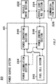
- Fig. 2 schematically shows an example of system configuration of a vehicle 20.
- the vehicle 20 comprises a power source system 40, a vehicle drive section 222, a vehicle control section 224 and a communication section 226.
- the power source system 40 includes a fuel cell system 242, a power accumulation section 244, a power converting section 246 and a power control section 248.
- Each portion of the vehicle 20 is configured to, for example, send and receive information to/from each other.
- the vehicle drive section 222 utilizes the power supplied by the power supply system 40 to drive each portion of the vehicle 20.
- the vehicle drive section 222 may be a motor for driving the vehicle 20.
- the vehicle drive section 222 may be an air conditioning equipment for regulating the air environment in the room space of the vehicle 20.
- the vehicle control section 224 controls the vehicle 20.
- the vehicle control section 224 may control the vehicle drive section 222.
- the vehicle control section 224 acquires the information indicating the state of the vehicle drive section 222 from various kinds of sensors positioned in the vehicle drive section 222.
- the vehicle control section 224 may control the action of the vehicle drive section 222.
- the vehicle control section 224 may control the power supply to the vehicle drive section 222.
- the vehicle control section 224 may control the power source system 40. For example, it acquires the information indicating the state of the power source system 40 from various kinds of sensors positioned in the power source system 40.
- the vehicle control section 224 may control the action of the power source system 40.
- the vehicle control section 224 controls the operation mode of the power source system 40.
- the operation mode can associate, for example, (i) a magnitude of the output power, (ii) a following property or responsiveness against the output instruction, (iii) a fuel efficiency or power generation efficiency, and (iv) one or more property selected among a group consisted of inhibition of deterioration, with the operation condition for prioritizing than other properties which are not selected.
- the communication section 226 sends and receives information between itself and an exterior information processing device.
- the communication section 226 sends and receives information between itself and at least either one of the preservation device 120 and the management server 140.
- the communication section 226 may send information received from the vehicle control section 224 to at least either one of the preservation device 120 and the management server 140.
- the communication section 226 may output the information received from at least either one of the preservation device 120 and the management server 140 to the vehicle control section 224.
- the communication section 226 may correspond to one or more communication method.
- the power converting section 246 converts the power.
- the power converting section 246 may convert a direct current into an alternate current, may convert an alternate current into a direct current, or may convert an inputted direct voltage into another direct voltage.
- the power converting section 246 may include a bidirectional DC-DC converter.
- the power control section 248 controls the power converting section 246.
- the power control section 248 may control the power converting section 246 to convert the power.
- the power control section 248 may control the power converting section 246 to accordingly control the timing of starting or stopping of power supply.
- the power control section 248 may control the power converting section 246 to accordingly control the supply destination of the inputted power.
- the vehicle drive section 222 may be an example of a work machine.
- the fuel cell system 242 may be an example of a power supply device.
- a vehicle As the moving body, a vehicle, a marine vessel, a flying object, etc. are exemplified.
- a marine vessel As the marine vessel, a ship, a hovercraft, a water bike, a submarine, a submersible craft, an underwater scooter, etc. can be exemplified.
- a flying object As the flying object, an air plane, an air ship or a balloon, a hot-air balloon, a helicopter, a drone, etc. can be exemplified.
- a pump, a blower, a sprayer, a cleaning machine, etc. As the cleaning apparatus, vacuum cleaner, washing machine, etc. are exemplified.
- each portion of the vehicle 20 at least a part thereof may be realized by a personal computer or a mobile terminal.
- a personal computer or a mobile terminal is utilized as the user interface of each portion of the vehicle 20.
- the mobile terminal a mobile phone, a smartphone, a PDA, a tablet, a notebook computer or a laptop computer, a wearable computer, etc. are exemplified.
- the above-described data processing device or storage device may store a program.
- the above-described program may be stored in a non-transitory computer-readable storage medium.
- the above-described program is performed by a processor to thereby make the above-described information processing device perform actions defined by said program.
- the program may be stored in a non-transitory computer-readable storage medium.
- the program may be stored in a computer readable medium such as a CD-ROM, a DVD-ROM, a memory, a hard disk, or may be stored in a storage device connected to a network.
- the program may be installed to a computer which configures at least a part of the vehicle 20 from a storage device connected to a computer readable medium or a network.
- the program may be performed to thereby make the computer function as at least a part of each portion of the vehicle 20.
- the program which makes the computer function as at least a part of each portion of the vehicle 20 may comprise a module which defines the action of each portion of the vehicle 20.
- This program or module coerces on the data processing device, input device, output device, storage device, etc., to accordingly make the computer function as each portion of the vehicle 20, or make the computer perform an information processing method at each portion of the vehicle 20.
- Information processing described in the program will, as said program is read by the computer, thereby function as a concrete means in which the software related to said program and various kinds of hardware resources of the vehicle 20 cooperate. And thus, the above-described concrete means realizes computation or processing of an information associated with the purpose of use of the computer in this embodiment, thereby the vehicle 20 associated with said purpose of use will be established
- Fig. 3 schematically shows an example of interior configuration of a fuel cell system 242.
- the fuel cell system 242 includes a fuel cell unit 42, a fuel supply unit 312, an oxidant agent supply unit 314, and a temperature regulation medium supply unit 316.
- the fuel cell unit 42 includes a communication connector 322, a power connector 324 and a utility connector 326 for power generation.
- the fuel cell unit 42 includes an FC control section 330, a power generation section 340, one or more sensor 342, one or more piping 344 and an auxiliary battery 350.
- the FC control section 330 may have a memory 332.
- the fuel cell unit 42 utilizes the fuel supplied from the fuel supply unit 312 and the fuel supplied from the oxidant agent supply unit 314, to generate power.
- the temperature of the fuel cell unit 42 is regulated by the temperature regulation medium supplied from the temperature regulation medium supply unit 316.
- the power generated by the fuel cell unit 42 is, for example, supplied to each portion of the vehicle 20, via the power converting section 246.
- the fuel cell unit 42 may control the action of at least one of the fuel supply unit 312, the oxidant agent supply unit 314 and the temperature regulation medium supply unit 316.
- the fuel cell unit 42 may act pursuant to the instruction from the power control section 248.
- the fuel cell unit 42 may be a unit, in which at least the FC control section 330, the power generation section 340, the piping 344 and various kinds of wirings are packaged.
- the fuel cell unit 42 may be a unit, in which at least the FC control section 330, the power generation section 340, the auxiliary battery 350, and the piping and the wirings are packaged.
- the components of the fuel cell unit 42 may be housed in a single enclosure, or may be housed in a plurality of enclosures separately.
- the fuel cell unit 42 is attached to the fuel cell system 242, for example, by being connected to the utility piping and the power cable positioned in the fuel cell system 242.
- the fuel cell unit 42 may be attached to the fuel cell system 242, by being connected to the utility piping, the power cable and the communication cable positioned in the fuel cell system 242. By this, the fuel cell unit 42 is mounted to the vehicle 20.
- the fuel cell unit 42 is attached to the fuel cell system 242 so as not to be easily detached by a general user of the vehicle 20.
- the fuel cell unit 42 is fixed, for example, to a predetermined position of the fuel cell system 242.
- the fuel cell unit 42 is detachably attached to the fuel cell system 242.
- a general user of the vehicle 20 can detach the fuel cell unit 42 from the fuel cell system 242.
- a general user of the vehicle 20 can, for example, attach the fuel cell unit 42 detached from the vehicle 20 to another work machine, to accordingly operate said other work machine with the power generated by the fuel cell unit 42.
- a manufacturer or a vendor of the vehicle 20 or the power source system 40 may be able to detach the fuel cell unit 42 from the fuel cell system 242 without largely impairing the integrity as a unit, in some cases.
- a manufacturer or a vendor of the vehicle 20 or the power source system 40 may be able to detach the fuel cell unit 42 from the fuel cell system 242 without dismantling the fuel cell unit 42, in some cases.
- An embodiment like this may be an example of the embodiment in which the fuel cell unit 42 is detachably attached to the fuel cell system 242.
- the fuel cell unit 42 is detached from the fuel cell system 242 and left in the atmosphere in such a state, deterioration progress of the fuel cell unit 42 is possibly accelerated. Especially, if the fuel cell unit 42 has been used for power generation and is thereafter detached from the fuel cell system 242, air as an oxidant agent remains in the inside of the fuel cell unit 42. The remaining air inside the fuel cell unit 42 can deteriorate the fuel cell stack of the fuel cell unit 42.
- the fuel cell unit 42 detached from the fuel cell system 242 is preserved in the preservation device 120.
- the preservation device 120 preserves the fuel cell unit 42 in a form to inhibit deterioration progress of the fuel cell unit 42.
- the preservation device 120 replaces the remaining air in the fuel cell unit 42 with the purge gas.
- the preservation device 120 may run the fuel cell unit 42 at a proper timing.
- the preservation device 120 runs the fuel cell unit 42 in an idling power generation mode or in a deterioration inhibition mode at a proper timing.
- humidity inside the fuel cell stack is properly kept. As a result, deterioration progress of the fuel cell unit 42 can be inhibited.
- the fuel supply unit 312 supplies a fuel for power generation to the fuel cell unit 42.
- the fuel for power generation may be a hydrogen, or may be a compound containing a hydrogen.
- the fuel supply unit 312 may comprise a sensor (not shown) for measuring the flow rate of the fuel and a flow rate regulation section (not shown) for regulating the flow rate of the fuel.
- the fuel supply unit 312 may act pursuant to the instruction from the fuel cell unit 42.
- the fuel supply unit 312 may supply fuel to the power generation section 340, utilizing the power via the piping 344.
- the fuel supply unit 312 may be positioned inside the power source system 40.
- the fuel supply unit 312 supplies a fuel to the power generation section 340, utilizing the power supplied from at least one of the power accumulation section 244, the power generation section 340 and the auxiliary battery 350.
- the fuel supply unit 312 supplies a fuel to the power generation section 340, utilizing the power supplied from the preservation device 120.
- the fuel supply unit 312 may supply a fuel to the power generation section 340, utilizing the power supplied from the preservation device 120 and the power supplied from at least either one of the power generation section 340 and the auxiliary battery 350.
- the oxidant agent supply unit 314 supplies an oxidant agent for power generation to the fuel cell unit 42.
- the oxidant agent may be an oxygen, or may be an air.
- the oxidant agent supply unit 314 may comprise a sensor (not shown) for measuring the flow rate of the oxidant agent and a flow rate regulation section (not shown) for regulating the flow rate of the oxidant agent.
- the oxidant agent supply unit 314 may act pursuant to the instruction from the fuel cell unit 42.
- the oxidant agent supply unit 314 may supply an oxidant agent to the power generation section 340, utilizing the power via the piping 344.
- the oxidant agent supply unit 314 may be positioned inside the power source system 40.
- the oxidant agent supply unit 314 supplies the oxidant agent to the power generation section 340, utilizing the power supplied from at least one of the power accumulation section 244, the power generation section 340 and the auxiliary battery 350.
- the oxidant agent supply unit 314 may supply an oxidant agent to the power generation section 340, utilizing the power supplied from the preservation device 120.
- the oxidant agent supply unit 314 may supply an oxidant agent to the power generation section 340, utilizing the power supplied from preservation device 120 and the power supplied from at least either one of the power generation section 340 and the auxiliary battery 350.
- the oxidant agent supply unit 314 may include a pump or a blower (not shown) for sucking air, serving as an oxidant agent, from outside the fuel cell system 242.
- the oxidant agent supply unit 314 may be connected to an air supply piping (not shown) positioned in the vehicle 20.
- the temperature regulation medium supply unit 316 supplies a temperature regulation medium for regulating the temperature of the power generation stack of the fuel cell unit 42 to the fuel cell unit 42.
- a temperature regulation medium water, an ethylene glycol, a long life coolant (called "LLC" in some cases.) are exemplified.
- the temperature regulation medium supply unit 316 may comprise a sensor (not shown) for measuring the flow rate of the temperature regulation medium and a flow rate regulation section (not shown) for regulating the flow rate of the temperature regulation medium.
- the temperature regulation medium supply unit 316 may act pursuant to the instruction from the fuel cell unit 42.
- the temperature regulation medium supply unit 316 may comprise a heat exchanger (not shown) for regulating the temperature of the temperature regulation medium. As the heat exchanger, a radiator is exemplified.
- the temperature regulation medium supply unit 316 may supply a temperature regulation medium to the power generation section 340, utilizing the power via the piping 344.
- the temperature regulation medium supply unit 316 may be positioned inside the power source system 40.
- the temperature regulation medium supply unit 316 supplies a temperature regulation medium to the power generation section 340, utilizing the power supplied from at least one of the power accumulation section 244, the power generation section 340 and the auxiliary battery 350.
- the temperature regulation medium supply unit 316 may supply a temperature regulation medium to the power generation section 340, utilizing the power supplied from the preservation device 120.
- the temperature regulation medium supply unit 316 may supply a temperature regulation medium to the power generation section 340, utilizing power supplied from preservation device 120 and the power supplied from at least either one of the power generation section 340 and the auxiliary battery 350.
- the communication connector 322 connects a communication cable or a communication apparatus positioned in the fuel cell unit 42 to a communication cable or a communication apparatus positioned in the fuel cell system 242.
- a communication cable or a communication apparatus positioned in the fuel cell unit 42, and a communication cable or a communication apparatus positioned in the fuel cell system 242, may be connected wiredly or wirelessly.
- the communication connector 322 may include a wireless communication apparatus.
- the fuel cell unit 42 may send and receive information to/from the communication apparatus positioned in the fuel cell system 242, the power control section 248 and the vehicle control section 224, via wireless communication apparatus.
- the fuel cell unit 42 may send and receive information between itself and the preservation device 120, via a wireless communication apparatus.
- the power connector 324 electrically connects a power cable positioned in the fuel cell unit 42 to a power cable positioned in the fuel cell system 242.
- the power cable positioned in the fuel cell unit 42 and a power cable positioned in the fuel cell system 242 may be connected wiredly or wirelessly.
- the communication connector 324 may include a wireless power supply apparatus.
- the fuel cell unit 42 may be electrically connected to the power converting section 246 or the vehicle drive section 222, via a wireless power supply apparatus. By this, transmitting and receiving of the power becomes possible between the fuel cell system 242 and the fuel cell unit 42. As a result, transmitting and receiving of the power becomes possible between the power converting section 246 and the fuel cell unit 42, and transmitting and receiving of the power becomes possible between the vehicle drive section 222 or the power accumulation section 244 and the fuel cell unit 42.
- the fuel cell unit 42 may be connected to the preservation device 120, via a wireless power supply apparatus.
- the utility connector 326 for power generation connects the utility piping positioned in the fuel cell unit 42 and the utility piping positioned in the fuel cell system 242.
- transmitting and receiving of the fuel becomes possible between the fuel supply unit 312 and the fuel cell unit 42.
- Transmitting and receiving of the oxidant agent becomes possible between the oxidant agent supply unit 314 and the fuel cell unit 42.
- Transmitting and receiving of a temperature regulation medium or a heat becomes possible between the temperature regulation medium supply unit 316 and the fuel cell unit 42.
- transmitting and receiving of a drainage water and an exhaust gas generated in association with the power generation at the fuel cell unit 42 becomes possible between the fuel cell unit 42 and the vehicle 20 or the fuel cell system 242.
- the FC control section 330 controls the fuel cell unit 42.
- the FC control section 330 controls the power generation of the fuel cell unit 42.
- the FC control section 330 may control at least one of the output voltage, the output current, the output power and the output rate of the fuel cell unit 42.
- the FC control section 330 may control at least one of the output voltage, the output current and the output rate of the power generation section 340.
- the FC control section 330 may control at least one of the output voltage, the output current, the output power and the output rate of the auxiliary battery 350.
- the FC control section 330 may control the action of at least one of the fuel supply unit 312, the oxidant agent supply unit 314 and the temperature regulation medium supply unit 316 to thereby control power generation of the fuel cell unit 42.
- the FC control section 330 may act pursuant to the instruction from the power control section 248.
- the FC control section 330 sends the information indicating the running state of each portion of the fuel cell unit 42 to the management server 140, for example, via the power control section 248.
- a running state an output power, an output voltage, an output current or an output rate is exemplified.
- the FC control section 330 may correlate the information indicating the running state of each portion of the fuel cell unit 42 with the information indicating the time, to send it to the management server 140.
- the FC control section 330 stores the information indicating the running state of each portion of the fuel cell unit 42 in the memory 332. As a running state, an output power, an output voltage, an output current or an output rate is exemplified. The FC control section 330 may correlate the information indicating the running state of each portion of the fuel cell unit 42 with the information indicating the time, to send it to the memory 332.
- the FC control section 330 may store the information indicating the running state of each portion of the fuel cell unit 42 in the memory 332, during the period when the fuel cell unit 42 is mounted to the vehicle 20 or the power source system 40.
- the FC control section 330 may store the information indicating the running state of each portion of the fuel cell unit 42 in the memory 332, during the period when the fuel cell unit 42 is preserved in the preservation device 120.
- the management server 140 can acquire the information indicating the fluctuation state of the surrounding environment of the fuel cell unit 42 in an ex-post manner.
- the oxidant agent supply unit 314 may be an example of the first oxidant agent supply section.
- the power generation section 340 may be an example of the fuel cell.
- the piping 344 may be an example of the oxidant agent supply passage.
- the utility connector 326 for power generation may be an example of the connecting portion for oxidant agent.
- the plurality of preservation containers 122 may be an example of the first preservation section and the second preservation section.
- Fig. 4 schematically shows an example of interior configuration of a utility connector 326 for power generation.
- the utility connector 326 for power generation comprises a main body 420, a plug 436, a plug 446, a plug 456, a plug 466, a plug 476 and a plug 486.
- the main body 420 is only required to have proper rigidity, and its detail is not particularly limited. Note that in this embodiment, detail of the main body 420 is explained taking a case where the plug 436, the plug 446, the plug 456, the plug 466, the plug 476 and the plug 486 are positioned in a single main body 420 as an example. However, the main body 420 is not limited to this embodiment. In another embodiment, the utility connector 326 for power generation may have a plurality of main bodies 420, and the plug 436, the plug 446, the plug 456, the plug 466, the plug 476 and the plug 486 may be positioned in the plurality of main bodies 420 in a distributed manner.
- the plug 436 is positioned inside the concave portion 438 formed on one plane of the main body 420. By this, breakage of the plug 436 is inhibited.
- the plug 436 connects the piping 434 positioned inside the fuel cell unit 42 and the piping for fuel positioned outside the fuel cell unit 42.
- the piping 434 is positioned inside the fuel cell unit 42, and supplies the fuel to the power generation section 340.
- the oxidant agent supply unit 314 can supply the fuel to the power generation section 340 under a state where the fuel cell unit 42 is attached to the power source system 40.
- the plug 446 is positioned inside the concave portion 448 formed on one plane of the main body 420. By this, breakage of the plug 446 is inhibited.
- the plug 446 connects the piping 444 positioned inside the fuel cell unit 42 and the piping for the oxidant agent positioned outside the fuel cell unit 42.
- the piping 444 is positioned inside the fuel cell unit 42, and supplies the oxidant agent to the power generation section 340.
- the fuel supply unit 312 can supply the oxidant agent to the power generation section 340 under a state where the fuel cell unit 42 is attached to the power source system 40.
- the plug 456 is positioned inside the concave portion 458 formed on one plane of the main body 420. By this, breakage of the plug 456 is inhibited.
- the plug 456 connects the piping 454 positioned inside the fuel cell unit 42 and the piping for supplying temperature regulation medium positioned outside the fuel cell unit 42.
- the piping 454 is positioned inside the fuel cell unit 42, and supplies the temperature regulation medium to the power generation section 340.
- the temperature regulation medium supply unit 316 can supply the temperature regulation medium to the power generation section 340 under a state where the fuel cell unit 42 is attached to the power source system 40.
- the plug 466 is positioned inside the concave portion 468 formed on one plane of the main body 420. By this, breakage of the plug 466 is inhibited.
- the plug 466 connects the piping 464 positioned inside the fuel cell unit 42 and the piping for collecting the temperature regulation medium positioned outside the fuel cell unit 42.
- the piping 464 is positioned inside the fuel cell unit 42, and discharges the temperature regulation medium which has been heat-exchanged.
- the temperature regulation medium supply unit 316 can collect the temperature regulation medium from the power generation section 340 under a state where the fuel cell unit 42 is attached to the power source system 40.
- the plug 476 is positioned inside the concave portion 478 formed on one plane of the main body 420. By this, breakage of the plug 476 is inhibited.
- the plug 476 connects the piping 474 positioned inside the fuel cell unit 42 and the piping for discharging the exhaust gas positioned outside the fuel cell unit 42.
- the piping 464 is positioned inside the fuel cell unit 42, and discharges the exhaust gas from the power generation section 340.
- the power generation section 340 can discharge the exhaust gas to the outside of the fuel cell unit 42 under a state where the fuel cell unit 42 is attached to the power source system 40.
- the plug 486 is positioned inside the concave portion 488 formed on one plane of the main body 420. By this, breakage of the plug 486 is inhibited.
- the plug 486 connects the piping 484 positioned inside the fuel cell unit 42 and the piping for discharging the drainage water positioned outside the fuel cell unit 42.
- the piping 464 is positioned inside the fuel cell unit 42, and discharges the drainage water from the power generation section 340.
- the power generation section 340 can discharge the drainage water to the outside of the fuel cell unit 42 under a state where the fuel cell unit 42 is attached to the power source system 40.
- the piping 444 may be an example of the oxidant agent supply passage.
- the plug 446 may be an example of the connecting portion for oxidant agent.
- the utility connector 326 for power generation comprises the plug 436, the plug 446, the plug 456, the plug 466, the plug 476 and the plug 486 as an example.
- the utility connector 326 for power generation is not limited to this embodiment.
- at least one of the plug 436, the plug 446, the plug 456, the plug 466, the plug 476 and the plug 486 may be a socket, or may be a piping connector of a different kind.
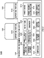
- Fig. 5 schematically shows an example of interior configuration of a preservation device 120.
- the preservation device 120 comprises one or more preservation container 122 and a preservation environment regulation section 124.
- the preservation environment regulation section 124 includes one or more supporting portion 510, a communication section 522, a hydrogen cylinder 532, a compressor 534, a nitrogen cylinder 542, a temperature regulation section 544, a humidity regulation section 546, a water tank 552, a condenser 554, a control section 560 and a power source 570.
- the power source 570 may include a power accumulation section 574 and a power converting section 576.
- a single supporting portion 510 supports a single preservation container 122 as an example.
- the supporting portion 510 is not limited to this embodiment.
- a single supporting portion 510 may support a plurality of preservation container 122. Detail of the supporting portion 510 will be described later.
- the communication section 522 sends and receives information between itself and an external information processing device.
- the communication section 522 sends and receives information between itself and at least either one of the vehicle 20 and the management server 140.
- the communication section 522 may send information received from the control section 560 to at least either one of the vehicle 20 and the management server 140.
- the communication section 522 may output the information received from at least either one of the vehicle 20 and the management server 140 to the control section 560.
- the communication section 522 may correspond to one or more communication method.
- the hydrogen cylinder 532 conserves the hydrogen.
- the hydrogen cylinder 532 supplies a hydrogen as the fuel to the power generation section 340 of the fuel cell unit 42, which is detached from the power source system 40 and preserved in the preservation container 122, via the supporting portion 510.
- the nitrogen cylinder 542 conserves a nitrogen gas.
- the nitrogen gas is utilized as the purge gas to be replaced with the remaining air or hydrogen inside the power generation section 340.
- the nitrogen gas is utilized as the purge gas to be replaced with the remaining hydrogen inside the piping 434.
- the nitrogen gas is utilized as the purge gas to be replaced with the remaining air inside the piping 444.
- the nitrogen cylinder 542 supplies, for example, the nitrogen as the purge gas to the power generation section 340 of the fuel cell unit 42, which is detached from the power source system 40 and preserved in the preservation container 122, via the supporting portion 510.
- the nitrogen gas may be utilized for regulating the interior environment of the preservation container 122.
- the nitrogen gas is utilized as the purge gas to be replaced with the remaining air or hydrogen inside the preservation container 122.
- the nitrogen cylinder 542 supplies, for example, the nitrogen as the purge gas to the inside of at least one of the one or more preservation container 122, via the supporting portion 510.
- at least one of its temperature and its humidity may be regulated before it is supplied to the preservation container 122.
- the temperature regulation section 544 regulates the temperature of the nitrogen supplied to each of the one or more preservation container 122.
- the temperature regulation section 544 may regulate the temperature of the nitrogen supplied to each of the one or more preservation container 122, each independently.
- the temperature regulation section 544 may supply, for example, temperature regulation medium for regulating the temperature of the power generation section 340 to the power generation section 340 of the fuel cell unit 42, which is detached from the power source system 40 and preserved in the preservation container 122, via the supporting portion 510. Moreover, the temperature regulation section 544 may regulate the temperature of the above-described temperature regulation medium, utilizing a heat exchanger (not shown) or the like.
- the humidity regulation section 546 regulates the humidity of the nitrogen supplied to each of the one or more preservation container 122.
- the humidity regulation section 546 may regulate the humidity of the nitrogen supplied to each of the one or more preservation container 122, each independently.
- the humidity regulation section 546 may regulate the humidity of the nitrogen, utilizing the water retained in the water tank 552.
- the humidity regulation section 546 receives a predetermined volume of water from the water tank 552.
- the humidity regulation section 546 heats the above-described water to generate water vapor.
- the humidity regulation section 546 mixes the generated water vapor and the nitrogen supplied from the nitrogen cylinder 542 to the preservation container 122. By this, the humidity of the nitrogen supplied to the preservation container 122 can be regulated.
- the humidity regulation section 546 makes at least a part of the nitrogen supplied from the nitrogen cylinder 542 to the preservation container 122 pass through the water retained in the water tank 552. By this, the humidity of the nitrogen supplied to the preservation container 122 can be regulated.
- the water tank 552 retains the water discharged from the power generation section 340. In one embodiment, the water tank 552 retains the drainage water discharged from the power generation section 340. In another embodiment, the water tank 552 retains a part of the water contained in the exhaust gas discharged from the power generation section 340. Concretely saying, during when the exhaust gas discharged from the power generation section 340 passes through the condenser 554, a part of the water vapor contained in the exhaust gas as well as of the splash water is condensed to accordingly generates liquid water. The water tank 552 retains water acquired in the condenser 554.
- control section 560 controls the action of each portion of the preservation environment regulation section 124.
- the interior environment of the fuel cell unit 42 preserved by the preservation device 120 is regulated.
- the interior environment of each of the one or more preservation container 122 is regulated.
- control section 560 may control the timing for supplying the hydrogen to each of the one or more fuel cell unit 42 preserved by the preservation container 122 from the hydrogen cylinder 532.
- the control section 560 may control the above-described hydrogen supply amount.
- the control section 560 may control the timing for supplying air to each of the one or more fuel cell unit 42 preserved by the preservation container 122 from the compressor 534.
- the control section 560 may control the above-described air supply amount.
- the control section 560 may control the timing for supplying the nitrogen to each of the one or more fuel cell unit 42 preserved by the preservation container 122 from the nitrogen cylinder 542.
- the control section 560 may control the above-described nitrogen supply amount.
- the control section 560 may supply the nitrogen intermittently, or may supply the nitrogen continuously.
- control section 560 periodically supplies the nitrogen to the fuel cell unit 42 to purge the hydrogen remaining inside at least one of the oxidant agent supply passage and the fuel supply passage of the fuel cell unit 42.
- the control section 560 may periodically supply the nitrogen to the fuel cell unit 42 at a flow rate larger than usual purging so as to flush the dusts accumulated inside the fuel cell unit 42.
- the control section 560 may control at least one of the temperature or the humidity of the nitrogen.
- the control section 560 may control the timing for supplying the nitrogen to the inside of each of the one or more preservation container 122 from the nitrogen cylinder 542.
- the control section 560 may control the above-described nitrogen supply amount.
- the control section 560 may supply the nitrogen intermittently, or may supply the nitrogen continuously.
- the control section 560 may control at least one of the temperature or the humidity of the nitrogen.
- the control section 560 may control the timing for circulating the temperature regulation medium by the temperature regulation section 544.
- the control section 560 may control the above-described temperature regulation medium circulation amount.
- the control section 560 may control the above-described temperature regulation medium supply temperature.
- control section 560 may control the action of each of the one or more fuel cell unit 42 preserved by the preservation device 120. In one embodiment, the control section 560 determines to run at least one of the one or more more fuel cell unit 42 preserved by the preservation device 120, at a given timing. The control section 560 may determine the power generation amount of each of at least one fuel cell unit 42. The control section 560 may determine the power generation mode of each of at least one fuel cell unit 42.
- control section 560 determines to run the fuel cell unit 42 in an idling power generation mode.
- the control section 560 may determine to run the fuel cell unit 42 in a deterioration inhibition mode.
- the fuel cell unit 42 compares with the idling power generation mode, and accordingly generates the power under an operating condition under which deterioration of the fuel cell stack is inhibited.
- the control section 560 may determine to periodically run each of the one or more fuel cell unit 42.
- the control section 560 may determine, based on the state of at least one of the interior environment and the surrounding environment of said given fuel cell unit 42, at least one of the followings: whether or not to run given fuel cell unit 42, the power generation amount of said given fuel cell unit 42, and the power generation mode of said given fuel cell unit 42.
- the preservation container 122 and the supporting portion 510 tightly seal and house the fuel cell unit 42 detached from the power source system 40. Moreover, the interior environment of the preservation container 122 can be maintained under a state different from the exterior environment of the preservation container 122. By this, the deterioration progress of the fuel cell unit 42 preserved inside the preservation container 122 can be inhibited. Further, according to this embodiment, under a state where the fuel cell unit 42 is housed inside the preservation container 122, a purge gas is injected into the inside of the fuel cell unit 42, or the fuel cell unit 42 generates a very small amount of power. By this, deterioration progress of the fuel cell unit 42 can be further inhibited.
- the hydrogen cylinder 532 may be an example of the fuel conserving section.
- the compressor 534 may be an example of the second oxidant agent supply section.
- the nitrogen cylinder 542 may be an example of the purge gas conserving section.
- the power source 570 may be an example of the power source.
- the hydrogen may be an example of the fuel.
- the air may be an example of the oxidant agent.
- the nitrogen may be an example of the purge gas.
- the main body 600 is only required to have proper rigidity, and its detail is not particularly limited.
- Each connecting portion between the main body 600 and each of the gas supply nozzle 622, the gas exhaust nozzle 623, the socket 632, the socket 642, the socket 652, the socket 662, the socket 672 and the socket 682 may be sealed by an appropriate sealing agent or sealing member.
- the preservation container 122 and the supporting portion 510 can tightly seal and house the fuel cell unit 42 under a state where various kinds of piping and wirings of the fuel cell unit 42 and their corresponding piping and wirings of the preservation device 120 are connected.
- the main body 600 is not limited to this embodiment.
- the supporting portion 510 may have a plurality of main bodies 600 so that the gas supply nozzle 622, the gas exhaust nozzle 623, the socket 632, the socket 642, the socket 652, the socket 662, the socket 672 and the socket 682 are positioned in a plurality of main bodies 600 in a distributed manner.
- a concave portion 610 is formed in a part of the region contacting with the bottom of the preservation container 122.
- a sealing member 612 is positioned at the concave portion 610.
- the sealing member 612 may be, for example, an O-ring.
- the preservation container 122 and the supporting portion 510 may tightly seal and house the fuel cell unit 42 detached from the power source system 40.
- an appropriate sealing member may be positioned at a region where each socket and the main body 600 contact.
- an appropriate sealing member may be positioned around each piping positioned inside the main body 600.
- each of one of the gas supply nozzle 622 supplies the nitrogen into the inside of the preservation container 122.
- nitrogen at least one of its temperature, humidity, oxygen concentration, hydrogen concentration and the particulate concentration may be regulated to a predetermined range.
- Each of the one or more gas supply nozzle 622 may be connected to the nitrogen cylinder 542 via the piping 620.
- a flow rate regulation valve 621 may be positioned between each of the one or more gas supply nozzle 622 and the nitrogen cylinder 542. The flow rate regulation valve 621 may act based on the instruction from the control section 560.
- one or more gas exhaust nozzle 623 discharges the gas inside the preservation container 122 to the outside of the preservation container 122 via the piping 624.
- one or more sensor 626 detects the state of the interior environment of the preservation container 122.
- a temperature, a humidity, an oxygen concentration, a hydrogen concentration, particulate concentration, etc. are exemplified.
- the information indicating the detection result of the one or more sensor 626 is outputted to the control section 560 via the signal cable 627.
- the socket 632 is connected to the plug 436 when the fuel cell unit 42 is preserved in the preservation container 122.
- the socket 632 may be connected to the hydrogen cylinder 532 via the piping 630.
- the hydrogen is supplied to the power generation section 340 from the hydrogen cylinder 532 via the piping 630 and the socket 632.
- One end of the piping 630 is connected to the socket 632, and the other end is connected to the hydrogen cylinder 532.
- a flow rate regulation valve 631 may be positioned between the socket 632 and the hydrogen cylinder 532.
- the flow rate regulation valve 631 may regulate the flow rate of the hydrogen supplied to the power generation section 340, by regulating the communication state of the piping 434 and the piping 630.
- the flow rate regulation valve 631 may act based on the instruction from the control section 560.
- the socket 632 is connected to the nitrogen cylinder 542 via the piping 690.
- the nitrogen is supplied to the power generation section 340 from the nitrogen cylinder 542 via the piping 690 and the socket 632.
- One end of the piping 690 is connected, for example, to a part of the piping 630.
- the other end of the piping 690 is connected to the nitrogen cylinder 542.
- a check valve 692 and a flow rate regulation valve 694 may be positioned between the connecting portion connecting the piping 690 to the piping 630 and the nitrogen cylinder 542.
- the flow rate regulation valve 694 may regulate the flow rate of the nitrogen supplied to the power generation section 340, by regulating the communication state of the piping 434 and the piping 690.
- the flow rate regulation valve 694 may act based on the instruction from the control section 560.
- the socket 642 is connected to the plug 446 when the fuel cell unit 42 is preserved in the preservation container 122.
- the socket 642 may be connected to the compressor 534 via the piping 640.
- the air is supplied to the power generation section 340 from the compressor 534 via the piping 640 and the socket 642.
- the socket 642 is positioned on one end of the piping 640, and the compressor 534 is positioned on the other end.
- the flow rate regulation valve 641 may be positioned between the socket 642 and the compressor 534.
- the flow rate regulation valve 641 may regulate the flow rate of the air supplied to the power generation section 340, by regulating the communication state of the piping 444 and the piping 640.
- the flow rate regulation valve 641 may act based on an instruction from the control section 560.
- the socket 642 is connected to the nitrogen cylinder 542 via the piping 690.
- the nitrogen is supplied to the power generation section 340 from the nitrogen cylinder 542 via the piping 690 and the socket 642.
- One end of the piping 690 is connected, for example, to a part of the piping 640.
- the other end of the piping 690 is connected to the nitrogen cylinder 542.
- a check valve 696 and a flow rate regulation valve 698 may be positioned between the connecting portion connecting the piping 690 to the piping 640 and the nitrogen cylinder 542.
- the flow rate regulation valve 698 may regulate the flow rate of the nitrogen supplied to the power generation section 340, by regulating the communication state of the piping 444 and the piping 690.
- the flow rate regulation valve 698 may act based on an instruction from the control section 560.
- the socket 652 is connected to the temperature regulation section 544 via the piping 650.
- the temperature regulation medium is supplied to the power generation section 340 via the piping 650 and the socket 652.
- the socket 662 is connected to the temperature regulation section 544 via the piping 664.
- the temperature regulation medium is discharged from the power generation section 340 via the socket 662 and the piping 664.
- the socket 682 is connected to the water tank 552 via the piping 684.
- the drainage water is discharged from the power generation section 340 via the socket 682 and the piping 684.
- the supporting portion 510 have the connecting member for electrically connecting the power source 570 of the preservation environment regulation section 124 and the power connector 324 of the fuel cell unit 42.
- the supporting portion 510 have a socket which can be coupled to the power connector 324 and a power cable for electrically connecting said socket to the power source 570.
- the power connector 324 may have a wireless power supply device. In this case, if the preservation environment regulation section 124 has a wireless power supply device, the supporting portion 510 may not necessarily have the above-described connecting member
- the piping 640 may be an example of the oxidant agent piping.
- the flow rate regulation valve 641 may be an example of the second regulation section.
- the socket 642 may be an example of the oxidant agent piping.
- the piping 690 may be an example of the purge gas piping.
- the flow rate regulation valve 694 may be an example of the purge gas flow rate regulation section.
- the flow rate regulation valve 698 may be an example of the purge gas flow rate regulation section and the first regulation section.
- Fig. 7 schematically shows an example of system configuration of a management server 140.
- the management server 140 comprises a history information acquisition section 720, a residual value calculation section 730, a preservation state management section 740, and a cell information storage section 750.
- the history information acquisition section 720 acquires the information indicating the running history of the fuel cell unit 42 during the period when the fuel cell unit 42 is attached to the power source system 40, via the communication section 226 of the vehicle 20.
- the history information acquisition section 720 acquires the information indicating the fluctuation history of the state of the surrounding environment of the fuel cell unit 42 during the period when the fuel cell unit 42 is attached to the power source system 40, via the communication section 226 of the vehicle 20.
- the history information acquisition section 720 acquires the information indicating the running history of the fuel cell unit 42 during the period when the fuel cell unit 42 is preserved in the preservation device 120, after the fuel cell unit 42, which was preserved in the preservation device 120, is attached to the power source system 40, via the communication section 226 of the vehicle 20.
- the history information acquisition section 720 acquires the information indicating the fluctuation history of the state of the surrounding environment of the fuel cell unit 42 during the period when the fuel cell unit 42 is preserved in the preservation device 120, after the fuel cell unit 42, which was preserved in the preservation device 120, is attached to the power source system 40, via the communication section 226 of the vehicle 20.
- the residual value calculation 730 assesses the value of each of the one or more fuel cell unit 42.
- the residual value calculation section 730 may store the assessment result related to the value (this may be called “residual value” in some cases) of each of the one or more fuel cell unit 42 to the cell information storage section 750.
- the residual value calculation section 730 acquires the information indicating the current power generating performance for each of the one or more fuel cell unit 42.
- the information indicating the power generating performance of each of the one or more fuel cell unit 42 can be acquired, for example, my means of running each of the one or more fuel cell unit 42 in the assessment mode for assessing the power generating performance.
- the residual value calculation section 730 may calculate the residual value of respective fuel cell units, based on the power generating performance of each of the one or more fuel cell unit 42.
- the residual value calculation section 730 may calculate the residual value of the one or more fuel cell unit 42, based on the history information acquired by the history information acquisition section 720.
- the residual value calculation section 730 may calculate, for example, the residual value of each of the one or more fuel cell unit 42, based on at least one of the running history of each of the one or more fuel cell unit 42 and the fluctuation history of the state of the surrounding environment of each of the one or more fuel cell unit 42.
- the residual value calculation section 730 takes one or more kind of history information related to the fuel cell unit 42 as the explanatory variable, and calculates the residual value of each of the one or more fuel cell unit 42 by employing a table, a function or a model which takes the residual value of the fuel cell unit 42 as the objective variable.
- the preservation state management section 740 may determine, based on the residual value of given fuel cell unit 42, at least one of the followings: whether or not to run said given fuel cell unit 42; the power generation amount of said given fuel cell unit 42; and the power generation mode of said given fuel cell unit 42.
- the preservation state management section 740 may determine, based on the residual value of given fuel cell unit 42, the running frequency of said given fuel cell unit 42.
- the preservation state management section 740 determines, for the fuel cell unit 42 for which the assessment by the residual value calculation section 730 satisfies the predefined conditions, among multiple fuel cell units preserved by the preservation device 120, to run said fuel cell unit 42 to generate a power.
- the predefined condition may be a condition that the assessment result is the lowest.
- the preservation state management section 740 may determine, for the above-described fuel cell unit 42, not to perform a process for inhibiting the deterioration progress.
- the power generated by the above-described fuel cell unit 42 may be utilized by the preservation device 120 or by other fuel cell unit 42 preserved in the preservation device 120.
- the cell information storage section 750 stores various kinds of information related to each of the one or more the fuel cell unit 42.
- the cell information storage section 750 stores, for each of the one or more fuel cell unit 42, various kinds of history information acquired by the history information acquisition section 720.
- the cell information storage section 750 may store, for each of the one or more fuel cell unit 42, the residual value calculated by the residual value calculation section 730.
- the history information acquisition section 720 may be an example of the environment information acquisition section.
- the residual value calculation section 730 may be an example of the value assessment section.
- the preservation state management section 740 may be an example of the preservation form determination section.
- Fig. 8 schematically shows an example of a computer 3000 in which multiple aspects of the present invention may be entirely or partially embodied.
- a part of the vehicle 20 may be realized by the computer 3000.
- at least one of the vehicle control section 224, the power control section 248 and the FC control section 330 is realized by the computer 3000.
- a part of the preservation device 120 may be realized by the computer 3000.
- the control section 560 is realized by the computer 3000.
- a part of the management server 140 may be realized by the computer 3000.
- the program installed in the computer 3000 can make the computer 3000 function as an operation associated with a device according to the embodiment of the present invention or as one or more "section" of said device, or make it perform said operation or said one or more "section", and/or make the computer 3000 perform a process according to the embodiment of the present invention or the stage of said process.
- Such program may be performed by the CPU 3012, so as to make the computer 3000 perform given operation associated with some or all of the flowcharts and the blocks of the block diagrams described in this specification.
- the computer 3000 includes the CPU 3012, the RAM 3014, the graphic controller 3016 and the display device 3018, and they are connected to each other by the host controller 3010.
- the computer 3000 further includes the communication interface 3022, the hard disk drive 3024, the DVD-ROM drive 3026 and the input/output unit such as an IC card drive, and they are connected to the host controller 3010 via the input/output controller 3020.
- the computer 3000 further includes the ROM 3030 and the legacy input/output unit such as the keyboard 3042, and they are connected to the input/output controller 3020 via the input/output chip 3040.
- the CPU 3012 acts pursuant to the program stored in the ROM 3030 and the RAM 3014, and controls respective units by them.
- the graphic controller 3016 acquires image data created by the CPU 3012 on a frame buffer or the like provided in the RAM 3014 or in itself, and causes the image data to be displayed on the display device 3018.
- the communication interface 3022 communicates with other electronic devices via the network.
- the hard disk drive 3024 stores the program and data to be used by the CPU 3012 in the computer 3000.
- the DVD-ROM drive 3026 reads a program or data from the DVD-ROM 3001, and provides the program or data to the hard disk drive 3024 via the RAM 3014.
- the IC card drive reads the program and data from the IC card, and/or writes the program and data to the IC card.
- the ROM 3030 stores a boot program, etc. executed by the computer 3000 at the time of activation, and/or a program dependent on the hardware of the computer 3000.
- the input/output chip 3040 may connect various input/output units to the input/output controller 3020, via a parallel port, a serial port, a keyboard port, a mouse port, etc.
- a program is provided by a computer-readable storage medium like the DVD-ROM 3001 or the IC card.
- a program is read from the computer-readable storage medium, and installed in the hard disk drive 3024, the RAM 3014 or the ROM 3030, which are the examples of computer-readable storage media, and then executed by the CPU 3012.
- Information processing described in these programs are read by the computer 3000, and result in cooperation between the program and the above-described various types of hardware resources.
- a device or method may be configured by realizing an operation or processing of information pursuant to the use of the computer 3000.
- the CPU 3012 may execute the communication program loaded on the RAM 3014 to instruct communication processing, based on the processing described in the communication program, to the communication interface 3022.
- the communication interface 3022 reads, under the control by the CPU 3012, the transmission data stored in the transmission buffer region provided in a storage medium such as a RAM 3014, a hard disk drive 3024, a DVD-ROM 3001 or an IC card, sends the transmission data so read to the network, or writes the received data received from the network into a reception buffer region etc. provided on the storage medium.
- the CPU 3012 may make all or the necessary portion of a file or a database stored in an external storage medium such as a hard disk drive 3024, a DVD-ROM drive 3026 (DVD-ROM 3001), or an IC card be able to be read by the RAM 3014, to accordingly perform various types of processing to the data on the RAM 3014. Then, the CPU 3012 may write back the processed data into an external storage medium.
- an external storage medium such as a hard disk drive 3024, a DVD-ROM drive 3026 (DVD-ROM 3001), or an IC card
- the CPU 3012 may perform, against the data read from the RAM 3014, various types of processing, including various types of operations designated by an instruction sequence of a program, which are described throughout this disclosure, an information processing, a condition judgment, a conditional branch, an unconditional branch, information search/replacement, etc., and write back the result to the RAM 3014.
- the CPU 3012 may search information in a file in a storage medium, in a database, etc.
- the CPU 3012 may search an entry matching with the condition in which the attribute value of the first attribute is designated from among said multiple entries, read the attribute value of the second attribute stored in said entry, and thereby acquire the attribute value of the second attribute associated with the first attribute which satisfies the predefined condition.
- a program or a software module explained above may be stored in a computer 3000 or in a computer-readable storage medium in proximity to the computer 3000. Furthermore, a storage medium such as a hard disk or a RAM provided within a server system connected to a dedicated communication network or the Internet can be used as a computer-readable storage medium, to thereby provide the above-described program to the computer 3000 via the network.
- a storage medium such as a hard disk or a RAM provided within a server system connected to a dedicated communication network or the Internet can be used as a computer-readable storage medium, to thereby provide the above-described program to the computer 3000 via the network.
Landscapes
- Chemical & Material Sciences (AREA)
- Chemical Kinetics & Catalysis (AREA)
- Electrochemistry (AREA)
- General Chemical & Material Sciences (AREA)
- Life Sciences & Earth Sciences (AREA)
- Engineering & Computer Science (AREA)
- Manufacturing & Machinery (AREA)
- Sustainable Development (AREA)
- Sustainable Energy (AREA)
- Fuel Cell (AREA)
- Electric Propulsion And Braking For Vehicles (AREA)
Abstract
Description
- The present invention relates to a preservation system.
- Lowering oxygen concentration inside an oxidant agent flow passage or a reducing agent flow passage of a fuel cell stack, as well as housing a fuel cell with a deoxidant inside the cover, for preventing deterioration during non-use period of a fuel cell stack, are known (for example, see
Patent Documents 1 to 3). -
- [Patent Document 1] Patent Unexamined Publication No.
2006-032323 - [Patent Document 2] Patent Unexamined Publication No.
2006-073297 - [Patent Document 3] Patent Unexamined Publication No.
2018-037271 - However, with the conventional preservation method, it is difficult to maintain for a long period a state where the oxygen concentration inside a fuel cell stack is low.
- In the first embodiment of the present invention, a preservation system is provided. The above-described preservation system preserves, for example, a power supply device. The above-described power supply device supplies the power to, for example, a work machine. The above-described power supply device is, for example, configured to be detachable to a work machine. The above-described power supply device includes, for example, a fuel cell. The above-described power supply device is, for example, positioned inside a power supply device and includes an oxidant agent supply passage for supplying the oxidant agent to a fuel cell. The above-described power supply device includes, for example, (i) a piping positioned outside the power supply device, and (ii) a connecting portion for oxidant agent for connecting the oxidant agent supply passage. The above-described preservation system comprises, for example, a preservation section for preserving a power supply device detached from a work machine. The above-described preservation system comprises, for example, a purge gas conserving section for conserving purge gas for purging the fuel cell and the oxidant agent supply passage. The above-described preservation system comprises, for example, a purge gas piping being a piping positioned outside the power supply device with one end thereof connected to the connecting portion for oxidant agent of the power supply device and the other end thereof connected to the purge gas conserving section. The above-described preservation system comprises, for example, a purge gas flow rate regulation section for regulating the purge gas flow rate to be supplied to the power supply device.
- In the above-described preservation system, the preservation section may store the power supply device, which has been used at least once in a work machine, under a state where the power supply device is detached from the work machine. In the above-described preservation system, the power supply device may include a first oxidant agent supply section for supplying oxidant agent to a fuel cell via the oxidant agent supply passage utilizing power, the oxidant agent supply section being positioned inside the power supply device. The above-described preservation system may comprise a power source for supplying power to the first oxidant agent supply section.
- In the above-described preservation system, the preservation section may include a first preservation section for preserving the first power supply device, provided with a first oxidant agent supply section. In the above-described preservation system, the preservation section may include a second preservation section for preserving a second power supply device not including a first oxidant agent supply section. The above-described preservation system may comprise a second oxidant agent supply section, positioned outside the power supply device, for supplying oxidant agent to the fuel cell of the second power supply device via the connecting portion for oxidant agent and the oxidant agent supply passage.
- In the above-described preservation system, the preservation section may include a housing section for tightly sealing and housing the power supply device. The above-described preservation system may comprise an oxidant agent piping, being a piping positioned outside the power supply device, with one end thereof connected to the connecting portion for oxidant agent of the power supply device, for supplying oxidant agent to the oxidant agent supply passage. In the above-described preservation system, the connecting portion between the oxidant agent piping and the housing section may be sealed.
- The above-described preservation system may comprise an oxidant agent piping, being a piping positioned outside the power supply device, with one end thereof connected to the connecting portion for oxidant agent of the power supply device, for supplying oxidant agent to the oxidant agent supply passage. In the above-described preservation system, the connecting portion for oxidant agent may connect the oxidant agent supply passage to the purge gas piping and the oxidant agent piping. In the above-described preservation system, the connecting portion for oxidant agent may include a first regulation section for regulating a communication state between the oxidant agent supply passage and the purge gas piping. In the above-described preservation system, the connecting portion for oxidant agent may include a second regulation section for regulating a communication state between the oxidant agent supply passage and the oxidant agent piping.
- The above-described preservation system may comprise a management section for managing a state of the power supply device preserved in the preservation section. In the above-described preservation system, the management section may include an environment information acquisition section for acquiring information indicating a state of the surrounding environment of the preservation section. In the above-described preservation system, the management section may include a value assessment section for assessing the value of the power supply device preserved in the preservation section, based on the information acquired by the environment information acquisition section.
- In the above-described preservation system, the management section may include a preservation form determination section for determining the preservation form of the power supply device, based on the value of the power supply device assessed by the value assessment section. In the above-described preservation system, the preservation form determination section may determine to generate power by running the power supply device preserved in the preservation section if assessment of a value of the power supply device by the value assessment section is smaller than the predefined reference.
- In the above-described preservation system, the preservation section may preserve a plurality of power supply devices. In the above-described preservation system, the value assessment section may assess a value of each of the plurality of power supply devices. In the above-described preservation system, the preservation form determination section may determine, for certain power supply device for which assessment by the value assessment section satisfies the predefined condition among the plurality of power supply devices, to generate power by running said certain power supply device.
- The summary clause does not necessarily describe all necessary features of the embodiments of the present invention. The present invention may also be a sub-combination of the features described above.
-
-
Fig. 1 schematically shows an example of system configuration of a fuelcell management system 100. -
Fig. 2 schematically shows an example of system configuration of avehicle 20. -
Fig. 3 schematically shows an example of interior configuration of afuel cell system 242. -
Fig. 4 schematically shows an example of interior configuration of autility connector 326 for power generation. -
Fig. 5 schematically shows an example of interior configuration of apreservation device 120. -
Fig. 6 schematically shows an example of interior configuration of a supportingportion 510. -
Fig. 7 schematically shows an example of system configuration of amanagement server 140. -
Fig. 8 schematically shows an example of system configuration of acomputer 3000. - Hereafter, the present invention will be explained through embodiments of the invention, however, the following embodiments do not limit the inventions according to the claims. Moreover, not all the combinations of the characteristics explained in the embodiments are necessarily essential for means for solving the problems of the inventions. Note that same or similar portions may be designated by the same reference numerals to omit overlapping explanation in some case.
-
Fig. 1 schematically shows an example of system configuration of a fuelcell management system 100. In this embodiment, the fuel cell management system comprises apreservation device 120 and amanagement sever 140. In this embodiment, thepreservation device 120 comprises one ormore preservation container 122 and a preservationenvironment regulation section 124. - In this embodiment, detail of the fuel
cell management system 100 is explained, taking a case where apower source system 40 mounted to avehicle 20 has a detachablefuel cell unit 42 and the fuelcell management system 100 preserves thefuel cell unit 42 detached from thepower source system 40 as an example. In this embodiment, the fuelcell management system 100 regulates a preservation state of thefuel cell unit 42 in order that deterioration progress of thefuel cell unit 42 during the preservation period will be inhibited. - In this embodiment, each of the
vehicle 20, thepreservation device 120 and themanagement server 140 can send and receive information among each other via thecommunication network 10. In this embodiment, thecommunication network 10 may be a transmission path for a wired communication, may be a transmission path for a wireless communication, and may be a combination of a transmission path for wireless communication and a transmission path for wired communication. - The
communication network 10 may include a radio packet communication network, the Internet, a P2P network, a dedicated line, a VPN, or a power line communication line. Thecommunication network 10 may include a mobile communication network such as a mobile phone line network. Thecommunication network 10 may include a wireless data communication network, such as wireless MAN (for example, WiMAX (registered trademark)), wireless LAN (for example, WiFi (registered trademark)), Bluetooth (registered trademark), Zigbee (registered trademark) and NFC (Near Field Communication). Thecommunication network 10 may include a V2X communication line, such as inter-vehicle communication and road-vehicle communication. - In this embodiment, the
vehicle 20 performs a work to transport at least either of a human and an item (this is called "transporting work" in some cases). Thevehicle 20 may perform a transporting work by a driver's operation, and also may perform a transporting work by automatic driving. For reference, work to be performed by thevehicle 20 is not limited to a transporting work. Thevehicle 20 may perform any work, utilizing power, instead of a transporting work, or along with a transporting work. - As the
vehicle 20, an automobile, a motorcycle, an electric train and the like are exemplified. As the motorcycle, (i) a motorbike, (ii) a three-wheeled motorbike, (iii) a standing ride type two-wheeled or three-wheeled vehicle equipped with a power unit, like a Segway (registered trademark), a kick board (registered trademark) with power unit, a skate board with power unit, are exemplified. Detail of thevehicle 20 will be described later. - In this embodiment, the
power source system 40 supplies the power to each part of thevehicle 20. Thepower source system 40 may supply power for thevehicle 20 to move. In this embodiment, thepower source system 40 supplies the power generated by thefuel cell unit 42 to thevehicle 20. A singlepower source system 40 may have a singlefuel cell unit 42, or a singlepower source system 40 may have a plurality offuel cell units 42. Detail of thepower source system 40 will be described later. - In this embodiment, the
fuel cell unit 42 is configured to be detachable to thepower source system 40 mounted to thevehicle 20. In one embodiment, afuel cell unit 42 detached from a givenpower source system 40 will be preserved in thepreservation device 120, and thereafter will be attached to said givenpower system 40. In another embodiment, afuel cell unit 42 detached from a givenpower source system 40 will be preserved in thepreservation device 120, and thereafter will be attached to anotherpower system 40. In another embodiment, after afuel cell unit 42 is detached from a givenpower source system 40, anotherfuel cell unit 42 preserved in thepreservation device 120 will be attached to said givenpower source system 40. Detail of thefuel cell unit 42 will be described later. - In this embodiment, the
preservation device 120 preserves one or morefuel cell unit 42 detached from each of the one or morepower source system 40. Thepreservation system 120 may preserve thefuel cell unit 42, which has been used at least once in thepower source system 40, under a state where thefuel cell unit 42 is detached from thepower source system 40. - In this embodiment, the one or
more preservation container 122 preserves thefuel cell unit 42 detached from thepower source system 40. Asingle preservation container 122 may house a singlefuel cell unit 42, or asingle preservation container 122 may house a plurality offuel cell units 42. Thepreservation container 122 may tightly seal and house thefuel cell unit 42. - As a material of the
preservation container 122, a non-breathable material may be used. By this, thepreservation container 122 may tightly seal and house thefuel cell unit 42. As the non-breathable material, for example, material with aeration rate, in anatmosphere 20 degrees Celsius, of 1000 mL/(m2. day. atm) or lower, preferably of 500 mL/(m2. day. atm) or lower, and more preferably of 200 mL/(m2 ·day. atm) or lower, is used. As the non-breathable material, (i) polyvinylidene chloride, (ii) material of OPP film with polyvinylidene chloride coated thereon (this is also called KOP in some cases), (iii) material of polyester film with polyvinylidene chloride coated thereon (this is also called KPET in some cases), (iv) material of nylon with polyvinylidene chloride coated thereon (this is also called KON in some cases), etc., are exemplified. - By this, the interior environment (this is called "atmosphere" in some cases) of the
preservation container 122 can be maintained under a state different from the exterior environment of thepreservation container 122. For example, the oxygen concentration inside thepreservation container 122 will be maintained under a state where it is lower than the oxygen concentration outside thepreservation container 122. Because the environment inside thepreservation container 122 is regulated, the preservation state of thefuel cell unit 42 can be managed. Detail of thepreservation container 122 will be described later. - In this embodiment, the preservation
environment regulation section 124 regulates the preservation environment of thefuel cell unit 42. For example, the preservationenvironment regulation section 124 regulates the environment inside each of the one ormore preservation container 122. More concretely, the preservationenvironment regulation section 124 regulates at least one among the temperature, humidity, oxygen concentration, hydrogen concentration and particulate concentration, of the inside of each of the one ormore preservation container 122. By this, deterioration progress of thefuel cell unit 42 can be inhibited. Detail of the preservationenvironment regulation section 124 will be described later. - In this embodiment, the
management server 140 manages one or morefuel cell unit 42. In one embodiment, themanagement server 140 manages the state of each of the one or morefuel cell unit 42. As the state of thefuel cell unit 42, a running state of thefuel cell unit 42, a preservation state of thefuel cell unit 42, etc., are exemplified. In another embodiment, themanagement server 140 manages the action of thepreservation device 120. By this, themanagement server 140 can manage the preservation state of each of the one or morefuel cell unit 42. Detail of themanagement server 140 will be described later. - The
vehicle 20 may be an example of a work machine. Transporting work may be an example of a work. Thepower source system 40 may be an example of a work machine. Thefuel cell unit 42 may be an example of a power supply device. The fuelcell management system 100 may be an example of a preservation system. Thepreservation device 120 may be an example of a preservation system. Thepreservation container 122 may be an example of a preservation section and a housing section. Themanagement server 140 may be an example of a management section. - Each portion of the fuel
cell management system 100 may be realized by a hardware, may be realized by a software, or may be realized by a hardware and a software. As for each portion of the fuelcell management system 100, at least a part thereof may be realized by a single server, or may be realized by a plurality of servers. As for each portion of the fuelcell management system 100, at least a part thereof may be realized on a virtual machine or on a cloud system. As for each portion of the fuelcell management system 100, information may be stored utilizing a distributed register technology or a distributed network such as a block chain. - As for each portion of the fuel
cell management system 100, at least a part thereof may be realized by a personal computer or a mobile terminal. For example, a personal computer or a mobile terminal is utilized as the user interface of each portion of the fuelcell management system 100. As the mobile terminal, a mobile phone, a smartphone, a PDA, a tablet, a notebook computer or a laptop computer, a wearable computer, etc., are exemplified. - If at least a part of the components configuring the fuel
cell management system 100 is realized by a software, the component realized by said software may be realized by activating a program which defines the action related to said component, in an information processing device having a common configuration. The above-described information processing device comprises, for example, (i) a data processing device including a processor such as a CPU or a GPU, or a ROM, a RAM, or a communication interface, etc., (ii) an input device such as a keyboard, a touch panel, a camera, a microphone, various kinds of sensors, a GPS receiver, (iii) an output device such as a display device, a speaker, a vibration device, and (iv) a storage device (including an external storage device.) such as a memory or an HDD. - In the above-described information processing device, the above-described data processing device or storage device may store a program. The above-described program may be stored in a non-transitory computer readable storage medium. The above-described program is performed by a processor to thereby make the above-described information processing device perform actions defined by said program.
- The program may be stored in a non-transitory computer readable storage medium. The program may be stored in a computer readable medium such as a CD-ROM, a DVD-ROM, a memory, a hard disk, or may be stored in a storage device connected to a network. The program may be installed to a computer which configures at least a part of the fuel
cell management system 100 from a storage device connected to a computer readable medium or a network. The program may be performed to thereby make the computer function as at least a part of each portion of the fuelcell management system 100. - The program which makes the computer function as at least a part of each portion of the fuel
cell management system 100 may comprise a module which defines the action of each portion of the fuelcell management system 100. This program or module coerces on the data processing device, input device, output device, storage device, etc., to accordingly make the computer function as each portion of the fuelcell management system 100, or make the computer perform an information processing method at each portion of the fuelcell management system 100. - Information processing described in the program will, as said program is read by the computer, thereby function as a concrete means in which the software related to said program and various kinds of hardware resources of the fuel
cell management system 100 cooperate. And thus, the above-described concrete means realizes computation or processing of an information associated with the purpose of use of the computer in this embodiment, thereby the fuelcell management system 100 associated with said purpose of use will be established -
Fig. 2 schematically shows an example of system configuration of avehicle 20. In this embodiment, thevehicle 20 comprises apower source system 40, avehicle drive section 222, avehicle control section 224 and acommunication section 226. In this embodiment, thepower source system 40 includes afuel cell system 242, apower accumulation section 244, apower converting section 246 and apower control section 248. Each portion of thevehicle 20 is configured to, for example, send and receive information to/from each other. - In this embodiment, the
vehicle drive section 222 utilizes the power supplied by thepower supply system 40 to drive each portion of thevehicle 20. Thevehicle drive section 222 may be a motor for driving thevehicle 20. Thevehicle drive section 222 may be an air conditioning equipment for regulating the air environment in the room space of thevehicle 20. - In this embodiment, the
vehicle control section 224 controls thevehicle 20. Thevehicle control section 224 may control thevehicle drive section 222. For example, thevehicle control section 224 acquires the information indicating the state of thevehicle drive section 222 from various kinds of sensors positioned in thevehicle drive section 222. Thevehicle control section 224 may control the action of thevehicle drive section 222. Thevehicle control section 224 may control the power supply to thevehicle drive section 222. - In this embodiment, the
vehicle control section 224 may control thepower source system 40. For example, it acquires the information indicating the state of thepower source system 40 from various kinds of sensors positioned in thepower source system 40. Thevehicle control section 224 may control the action of thepower source system 40. For example, if thepower source system 40 includes multiple operation modes, thevehicle control section 224 controls the operation mode of thepower source system 40. The operation mode can associate, for example, (i) a magnitude of the output power, (ii) a following property or responsiveness against the output instruction, (iii) a fuel efficiency or power generation efficiency, and (iv) one or more property selected among a group consisted of inhibition of deterioration, with the operation condition for prioritizing than other properties which are not selected. - In this embodiment, the
communication section 226 sends and receives information between itself and an exterior information processing device. For example, thecommunication section 226 sends and receives information between itself and at least either one of thepreservation device 120 and themanagement server 140. Thecommunication section 226 may send information received from thevehicle control section 224 to at least either one of thepreservation device 120 and themanagement server 140. Thecommunication section 226 may output the information received from at least either one of thepreservation device 120 and themanagement server 140 to thevehicle control section 224. Thecommunication section 226 may correspond to one or more communication method. - In this embodiment, the
fuel cell system 242 comprises thefuel cell unit 42. Thefuel cell system 242 may supply the power generated by thefuel cell unit 42 to thevehicle 20. For example, thefuel cell system 242 supplies the power generated by thefuel cell unit 42 to thevehicle drive section 222. Detail of thefuel cell system 242 will be described later. - In this embodiment, the
power accumulation section 244 accumulates the power. Thepower accumulation section 244 may supply accumulated power to thevehicle 20. For example, thepower accumulation section 244 supplies the accumulated power to thevehicle drive section 222. - In this embodiment, the
power converting section 246 converts the power. Thepower converting section 246 may convert a direct current into an alternate current, may convert an alternate current into a direct current, or may convert an inputted direct voltage into another direct voltage. Thepower converting section 246 may include a bidirectional DC-DC converter. - The
power converting section 246 may switch the power distribution state. Thepower converting section 246 may switch the supply destination of the inputted power. Thepower converting section 246 may supply the power generated by thefuel cell system 242 to thevehicle drive section 222. Thepower converting section 246 may supply the power generated by thefuel cell system 242 to thepower accumulation section 244. Thepower converting section 246 may supply the power accumulated in thepower accumulation section 244 to thefuel cell system 242. Thepower converting section 246 may supply the power accumulated in thepower accumulation section 244 to thevehicle drive section 222. Thepower converting section 246 may supply a regenerative power from thevehicle drive section 222 to thepower accumulation section 244. - In this embodiment, the
power control section 248 controls thepower converting section 246. Thepower control section 248 may control thepower converting section 246 to convert the power. Thepower control section 248 may control thepower converting section 246 to accordingly control the timing of starting or stopping of power supply. Thepower control section 248 may control thepower converting section 246 to accordingly control the supply destination of the inputted power. - The
vehicle drive section 222 may be an example of a work machine. Thefuel cell system 242 may be an example of a power supply device. - In this embodiment, detail of a work machine for performing a work has been explained, taking a case where the
vehicle 20 performs a transporting work as an example. However, the work machine is not limited to thevehicle 20. As other examples of work machines, a conveyance apparatus, a transportation apparatus, a cleaning apparatus, an air conditioning apparatus, a lighting apparatus, a robot, etc. are exemplified. As the conveyance apparatus, a moving body, a heavy machinery, an agricultural machine, a snow removing machine, an elevator, an escalator, etc. are exemplified. - As the moving body, a vehicle, a marine vessel, a flying object, etc. are exemplified. As the marine vessel, a ship, a hovercraft, a water bike, a submarine, a submersible craft, an underwater scooter, etc. can be exemplified. As the flying object, an air plane, an air ship or a balloon, a hot-air balloon, a helicopter, a drone, etc. can be exemplified. As the transportation apparatus, a pump, a blower, a sprayer, a cleaning machine, etc. are exemplified. As the cleaning apparatus, vacuum cleaner, washing machine, etc. are exemplified.
- Each portion of the
vehicle 20 may be realized by a hardware, may be realized by a software, or may be realized by a hardware and a software. As for each portion of thevehicle 20, at least a part thereof may be realized by a single server, or may be realized by a plurality of servers. As for each portion of thevehicle 20, at least a part thereof may be realized on a virtual machine or on a cloud system. For example, an artificial intelligence realized on the above-described server, virtual machine or cloud system may perform a part of the information processing in each portion of thevehicle 20. Each portion of thevehicle 20 may store information utilizing a distributed register technology or a distributed network, such as a block chain. - As for each portion of the
vehicle 20, at least a part thereof may be realized by a personal computer or a mobile terminal. For example, a personal computer or a mobile terminal is utilized as the user interface of each portion of thevehicle 20. As the mobile terminal, a mobile phone, a smartphone, a PDA, a tablet, a notebook computer or a laptop computer, a wearable computer, etc. are exemplified. - If at least a part of the components configuring the
vehicle 20 is realized by a software, the component realized by said software may be realized by activating a program which defines the action related to said component, in an information processing device having a common configuration. The above-described information processing device comprises, for example, (i) a data processing device including a processor such as a CPU or a GPU, or a ROM, a RAM, or a communication interface, etc., (ii) an input device such as a keyboard, a touch panel, a camera, a microphone, various kinds of sensors, a GPS receiver, (iii) an output device such as a display device, a speaker, a vibration device, and (iv) a storage device (including an external storage device.) such as a memory or an HDD. - In the above-described information processing device, the above-described data processing device or storage device may store a program. The above-described program may be stored in a non-transitory computer-readable storage medium. The above-described program is performed by a processor to thereby make the above-described information processing device perform actions defined by said program.
- The program may be stored in a non-transitory computer-readable storage medium. The program may be stored in a computer readable medium such as a CD-ROM, a DVD-ROM, a memory, a hard disk, or may be stored in a storage device connected to a network. The program may be installed to a computer which configures at least a part of the
vehicle 20 from a storage device connected to a computer readable medium or a network. The program may be performed to thereby make the computer function as at least a part of each portion of thevehicle 20. - The program which makes the computer function as at least a part of each portion of the
vehicle 20 may comprise a module which defines the action of each portion of thevehicle 20. This program or module coerces on the data processing device, input device, output device, storage device, etc., to accordingly make the computer function as each portion of thevehicle 20, or make the computer perform an information processing method at each portion of thevehicle 20. - Information processing described in the program will, as said program is read by the computer, thereby function as a concrete means in which the software related to said program and various kinds of hardware resources of the
vehicle 20 cooperate. And thus, the above-described concrete means realizes computation or processing of an information associated with the purpose of use of the computer in this embodiment, thereby thevehicle 20 associated with said purpose of use will be established -
Fig. 3 schematically shows an example of interior configuration of afuel cell system 242. In this embodiment, thefuel cell system 242 includes afuel cell unit 42, afuel supply unit 312, an oxidantagent supply unit 314, and a temperature regulationmedium supply unit 316. In this embodiment, thefuel cell unit 42 includes acommunication connector 322, apower connector 324 and autility connector 326 for power generation. In this embodiment, thefuel cell unit 42 includes anFC control section 330, apower generation section 340, one ormore sensor 342, one ormore piping 344 and anauxiliary battery 350. In this embodiment, theFC control section 330 may have amemory 332. - In this embodiment, the
fuel cell unit 42 utilizes the fuel supplied from thefuel supply unit 312 and the fuel supplied from the oxidantagent supply unit 314, to generate power. The temperature of thefuel cell unit 42 is regulated by the temperature regulation medium supplied from the temperature regulationmedium supply unit 316. The power generated by thefuel cell unit 42 is, for example, supplied to each portion of thevehicle 20, via thepower converting section 246. In this embodiment, thefuel cell unit 42 may control the action of at least one of thefuel supply unit 312, the oxidantagent supply unit 314 and the temperature regulationmedium supply unit 316. Thefuel cell unit 42 may act pursuant to the instruction from thepower control section 248. - In this embodiment, the
fuel cell unit 42 may be a unit, in which at least theFC control section 330, thepower generation section 340, the piping 344 and various kinds of wirings are packaged. Thefuel cell unit 42 may be a unit, in which at least theFC control section 330, thepower generation section 340, theauxiliary battery 350, and the piping and the wirings are packaged. The components of thefuel cell unit 42 may be housed in a single enclosure, or may be housed in a plurality of enclosures separately. - In this embodiment, the
fuel cell unit 42 is attached to thefuel cell system 242, for example, by being connected to the utility piping and the power cable positioned in thefuel cell system 242. Thefuel cell unit 42 may be attached to thefuel cell system 242, by being connected to the utility piping, the power cable and the communication cable positioned in thefuel cell system 242. By this, thefuel cell unit 42 is mounted to thevehicle 20. - In one embodiment, the
fuel cell unit 42 is attached to thefuel cell system 242 so as not to be easily detached by a general user of thevehicle 20. Thefuel cell unit 42 is fixed, for example, to a predetermined position of thefuel cell system 242. - In another embodiment, the
fuel cell unit 42 is detachably attached to thefuel cell system 242. By this, even a general user of thevehicle 20 can detach thefuel cell unit 42 from thefuel cell system 242. A general user of thevehicle 20 can, for example, attach thefuel cell unit 42 detached from thevehicle 20 to another work machine, to accordingly operate said other work machine with the power generated by thefuel cell unit 42. - Note that, even in a case where the
fuel cell unit 42 is attached to thefuel cell system 242 so as not to be easily detached by a general user of thevehicle 20, a manufacturer or a vendor of thevehicle 20 or thepower source system 40 may be able to detach thefuel cell unit 42 from thefuel cell system 242 without largely impairing the integrity as a unit, in some cases. For example, a manufacturer or a vendor of thevehicle 20 or thepower source system 40 may be able to detach thefuel cell unit 42 from thefuel cell system 242 without dismantling thefuel cell unit 42, in some cases. An embodiment like this may be an example of the embodiment in which thefuel cell unit 42 is detachably attached to thefuel cell system 242. - If the
fuel cell unit 42 is detached from thefuel cell system 242 and left in the atmosphere in such a state, deterioration progress of thefuel cell unit 42 is possibly accelerated. Especially, if thefuel cell unit 42 has been used for power generation and is thereafter detached from thefuel cell system 242, air as an oxidant agent remains in the inside of thefuel cell unit 42. The remaining air inside thefuel cell unit 42 can deteriorate the fuel cell stack of thefuel cell unit 42. - Therefore, according to this embodiment, the
fuel cell unit 42 detached from thefuel cell system 242 is preserved in thepreservation device 120. Thepreservation device 120 preserves thefuel cell unit 42 in a form to inhibit deterioration progress of thefuel cell unit 42. For example, thepreservation device 120 replaces the remaining air in thefuel cell unit 42 with the purge gas. Thepreservation device 120 may run thefuel cell unit 42 at a proper timing. For example, thepreservation device 120 runs thefuel cell unit 42 in an idling power generation mode or in a deterioration inhibition mode at a proper timing. By this, for example, humidity inside the fuel cell stack is properly kept. As a result, deterioration progress of thefuel cell unit 42 can be inhibited. - In this embodiment, the
fuel supply unit 312 supplies a fuel for power generation to thefuel cell unit 42. The fuel for power generation may be a hydrogen, or may be a compound containing a hydrogen. Thefuel supply unit 312 may comprise a sensor (not shown) for measuring the flow rate of the fuel and a flow rate regulation section (not shown) for regulating the flow rate of the fuel. Thefuel supply unit 312 may act pursuant to the instruction from thefuel cell unit 42. - The
fuel supply unit 312 may supply fuel to thepower generation section 340, utilizing the power via thepiping 344. Thefuel supply unit 312 may be positioned inside thepower source system 40. In one embodiment, where thefuel cell system 242 is attached to thepower source system 40, thefuel supply unit 312 supplies a fuel to thepower generation section 340, utilizing the power supplied from at least one of thepower accumulation section 244, thepower generation section 340 and theauxiliary battery 350. In another embodiment, where thefuel cell system 242 is preserved in thepreservation device 120, thefuel supply unit 312 supplies a fuel to thepower generation section 340, utilizing the power supplied from thepreservation device 120. In another embodiment, where thefuel cell system 242 is preserved in thepreservation system 120, thefuel supply unit 312 may supply a fuel to thepower generation section 340, utilizing the power supplied from thepreservation device 120 and the power supplied from at least either one of thepower generation section 340 and theauxiliary battery 350. - In this embodiment, the oxidant
agent supply unit 314 supplies an oxidant agent for power generation to thefuel cell unit 42. The oxidant agent may be an oxygen, or may be an air. The oxidantagent supply unit 314 may comprise a sensor (not shown) for measuring the flow rate of the oxidant agent and a flow rate regulation section (not shown) for regulating the flow rate of the oxidant agent. The oxidantagent supply unit 314 may act pursuant to the instruction from thefuel cell unit 42. - The oxidant
agent supply unit 314 may supply an oxidant agent to thepower generation section 340, utilizing the power via thepiping 344. The oxidantagent supply unit 314 may be positioned inside thepower source system 40. In one embodiment, where thefuel cell system 242 is attached to thepower source system 40, the oxidantagent supply unit 314 supplies the oxidant agent to thepower generation section 340, utilizing the power supplied from at least one of thepower accumulation section 244, thepower generation section 340 and theauxiliary battery 350. In another embodiment, where thefuel cell system 242 is preserved in thepreservation device 120, the oxidantagent supply unit 314 may supply an oxidant agent to thepower generation section 340, utilizing the power supplied from thepreservation device 120. In another embodiment, where thefuel cell system 242 is preserved in thepreservation system 120, the oxidantagent supply unit 314 may supply an oxidant agent to thepower generation section 340, utilizing the power supplied frompreservation device 120 and the power supplied from at least either one of thepower generation section 340 and theauxiliary battery 350. - The oxidant
agent supply unit 314 may include a pump or a blower (not shown) for sucking air, serving as an oxidant agent, from outside thefuel cell system 242. The oxidantagent supply unit 314 may be connected to an air supply piping (not shown) positioned in thevehicle 20. - In this embodiment, the temperature regulation
medium supply unit 316 supplies a temperature regulation medium for regulating the temperature of the power generation stack of thefuel cell unit 42 to thefuel cell unit 42. As the temperature regulation medium, water, an ethylene glycol, a long life coolant (called "LLC" in some cases.) are exemplified. The temperature regulationmedium supply unit 316 may comprise a sensor (not shown) for measuring the flow rate of the temperature regulation medium and a flow rate regulation section (not shown) for regulating the flow rate of the temperature regulation medium. The temperature regulationmedium supply unit 316 may act pursuant to the instruction from thefuel cell unit 42. The temperature regulationmedium supply unit 316 may comprise a heat exchanger (not shown) for regulating the temperature of the temperature regulation medium. As the heat exchanger, a radiator is exemplified. - The temperature regulation
medium supply unit 316 may supply a temperature regulation medium to thepower generation section 340, utilizing the power via thepiping 344. The temperature regulationmedium supply unit 316 may be positioned inside thepower source system 40. In one embodiment, where thefuel cell system 242 is attached to thepower source system 40, the temperature regulationmedium supply unit 316 supplies a temperature regulation medium to thepower generation section 340, utilizing the power supplied from at least one of thepower accumulation section 244, thepower generation section 340 and theauxiliary battery 350. In another embodiment, where thefuel cell system 242 is preserved in thepreservation system 120, the temperature regulationmedium supply unit 316 may supply a temperature regulation medium to thepower generation section 340, utilizing the power supplied from thepreservation device 120. In another embodiment, where thefuel cell system 242 is preserved in thepreservation system 120, the temperature regulationmedium supply unit 316 may supply a temperature regulation medium to thepower generation section 340, utilizing power supplied frompreservation device 120 and the power supplied from at least either one of thepower generation section 340 and theauxiliary battery 350. - In this embodiment, the
communication connector 322 connects a communication cable or a communication apparatus positioned in thefuel cell unit 42 to a communication cable or a communication apparatus positioned in thefuel cell system 242. A communication cable or a communication apparatus positioned in thefuel cell unit 42, and a communication cable or a communication apparatus positioned in thefuel cell system 242, may be connected wiredly or wirelessly. - The
communication connector 322 may include a wireless communication apparatus. Thefuel cell unit 42 may send and receive information to/from the communication apparatus positioned in thefuel cell system 242, thepower control section 248 and thevehicle control section 224, via wireless communication apparatus. Thefuel cell unit 42 may send and receive information between itself and thepreservation device 120, via a wireless communication apparatus. - In this embodiment, the
power connector 324 electrically connects a power cable positioned in thefuel cell unit 42 to a power cable positioned in thefuel cell system 242. The power cable positioned in thefuel cell unit 42 and a power cable positioned in thefuel cell system 242 may be connected wiredly or wirelessly. - The
communication connector 324 may include a wireless power supply apparatus. Thefuel cell unit 42 may be electrically connected to thepower converting section 246 or thevehicle drive section 222, via a wireless power supply apparatus. By this, transmitting and receiving of the power becomes possible between thefuel cell system 242 and thefuel cell unit 42. As a result, transmitting and receiving of the power becomes possible between thepower converting section 246 and thefuel cell unit 42, and transmitting and receiving of the power becomes possible between thevehicle drive section 222 or thepower accumulation section 244 and thefuel cell unit 42. Thefuel cell unit 42 may be connected to thepreservation device 120, via a wireless power supply apparatus. - In this embodiment, the
utility connector 326 for power generation connects the utility piping positioned in thefuel cell unit 42 and the utility piping positioned in thefuel cell system 242. By this, transmitting and receiving of the utility to be utilized for the operation of thefuel cell unit 42 becomes possible between thefuel cell system 242 and thefuel cell unit 42. As a result, transmitting and receiving of the utility becomes possible between thevehicle 20 or thefuel cell system 242 and thefuel cell unit 42. - For example, transmitting and receiving of the fuel becomes possible between the
fuel supply unit 312 and thefuel cell unit 42. Transmitting and receiving of the oxidant agent becomes possible between the oxidantagent supply unit 314 and thefuel cell unit 42. Transmitting and receiving of a temperature regulation medium or a heat becomes possible between the temperature regulationmedium supply unit 316 and thefuel cell unit 42. Also, transmitting and receiving of a drainage water and an exhaust gas generated in association with the power generation at thefuel cell unit 42 becomes possible between thefuel cell unit 42 and thevehicle 20 or thefuel cell system 242. - In this embodiment, the
FC control section 330 controls thefuel cell unit 42. For example, theFC control section 330 controls the power generation of thefuel cell unit 42. TheFC control section 330 may control at least one of the output voltage, the output current, the output power and the output rate of thefuel cell unit 42. TheFC control section 330 may control at least one of the output voltage, the output current and the output rate of thepower generation section 340. TheFC control section 330 may control at least one of the output voltage, the output current, the output power and the output rate of theauxiliary battery 350. TheFC control section 330 may control the action of at least one of thefuel supply unit 312, the oxidantagent supply unit 314 and the temperature regulationmedium supply unit 316 to thereby control power generation of thefuel cell unit 42. TheFC control section 330 may act pursuant to the instruction from thepower control section 248. - In one embodiment, the
FC control section 330 sends the information indicating the running state of each portion of thefuel cell unit 42 to themanagement server 140, for example, via thepower control section 248. As a running state, an output power, an output voltage, an output current or an output rate is exemplified. TheFC control section 330 may correlate the information indicating the running state of each portion of thefuel cell unit 42 with the information indicating the time, to send it to themanagement server 140. - The
FC control section 330 may send the information indicating the running state of each portion of thefuel cell unit 42 to themanagement server 140, during the period when thefuel cell unit 42 is mounted to thevehicle 20 or thepower source system 40. TheFC control section 330 may send the information indicating the running state of each portion of thefuel cell unit 42 to themanagement server 140, during the period when thefuel cell unit 42 is preserved in thepreservation device 120. - In another embodiment, the
FC control section 330 stores the information indicating the running state of each portion of thefuel cell unit 42 in thememory 332. As a running state, an output power, an output voltage, an output current or an output rate is exemplified. TheFC control section 330 may correlate the information indicating the running state of each portion of thefuel cell unit 42 with the information indicating the time, to send it to thememory 332. - The
FC control section 330 may store the information indicating the running state of each portion of thefuel cell unit 42 in thememory 332, during the period when thefuel cell unit 42 is mounted to thevehicle 20 or thepower source system 40. TheFC control section 330 may store the information indicating the running state of each portion of thefuel cell unit 42 in thememory 332, during the period when thefuel cell unit 42 is preserved in thepreservation device 120. By this, even if, for example, thefuel cell unit 42 runs during a period when it is unable to communicate with themanagement server 140, themanagement server 140 can acquire the information indicating the running state of each portion of thefuel cell unit 42 in an ex-post manner. - For example, even if the
fuel cell unit 42 is unable to communicate with themanagement server 140 during the period when thefuel cell unit 42 is preserved in thepreservation device 120, thefuel cell unit 42 is taken out from thepreservation device 120 to consequently mounted to thevehicle 20, and thereafter thevehicle control section 224 reads the information stored in thememory 332 of thefuel cell unit 42 and sends said information to themanagement server 140. By this, themanagement server 140 can acquire the information indicating the running state of each portion of thefuel cell unit 42 in an ex-post manner. - In this embodiment, the
FC control section 330 acquires the information indicating the detection result by each sensor from each of the one ormore sensor 342. In one embodiment, theFC control section 330 sends the information indicating the detection result by each sensor to themanagement server 140, for example, via thepower control section 248. TheFC control section 330 may correlate the information indicating the detection result by each sensor with the information indicating the time, to send it to themanagement server 140. TheFC control section 330 may send the information indicating the detection result by each sensor to themanagement server 140, during the period when thefuel cell unit 42 is mounted to thevehicle 20 or thepower source system 40. TheFC control section 330 may send the information indicating the detection result by each sensor to themanagement server 140, during the period when thefuel cell unit 42 is preserved in thepreservation device 120. - In another embodiment, the
FC control section 330 stores the information indicating the detection result of each sensor to thememory 332. TheFC control section 330 may correlate the information indicating the detection result by each sensor with the information indicating the time, to store it in thememory 332. TheFC control section 330 may store the information indicating the detection result by each sensor to thememory 332, during the period when thefuel cell unit 42 is mounted to thevehicle 20 or thepower source system 40. TheFC control section 330 may store the information indicating the detection result by each sensor in thememory 332, during the period when thefuel cell unit 42 is preserved in thepreservation device 120. - By this, even if, for example, the state of the surrounding environment of the
fuel cell unit 42 fluctuates during the period when thefuel cell unit 42 is unable to communicate with themanagement server 140, themanagement server 140 can acquire the information indicating the fluctuation of the state of said surrounding environment state in an ex-post manner. As the state of the surrounding environment, a temperature, a humidity, an oxygen concentration, a hydrogen concentration, etc. are exemplified. - For example, even if the
fuel cell unit 42 is unable to communicate with themanagement server 140 during the period when thefuel cell unit 42 is preserved in thepreservation device 120, thefuel cell unit 42 is taken out from thepreservation device 120 to consequently mounted to thevehicle 20, and thereafter thevehicle control section 224 reads the information stored in thememory 332 of thefuel cell unit 42 and sends said information to themanagement server 140. By this, themanagement server 140 can acquire the information indicating the fluctuation state of the surrounding environment of thefuel cell unit 42 in an ex-post manner. - In this embodiment, the
memory 332 stores various kinds of information related to thefuel cell unit 42. For example, thememory 332 stores the identification information of thefuel cell unit 42. Thememory 332 may store the information acquired from theFC control section 330. Thememory 332 may store the information acquired from thepreservation device 120. - For example, the
memory 332 acquires, from theFC control section 330, identification information of at least one of thevehicle 20, thepower source system 40 and thefuel cell system 242, to which thefuel cell unit 42 is mounted, and stores said information. Thememory 332 may correlate identification information of at least one of thevehicle 20, thepower source system 40 and thefuel cell system 242, to which thefuel cell unit 42 is mounted, with the information indicating the time when thefuel cell unit 42 is mounted to at least one of thevehicle 20, thepower source system 40 and thefuel cell system 242, to thereafter store it. - For example, the
memory 332 acquires the identification information of thepreservation device 120, in which thefuel cell unit 42 is preserved, from theFC control section 330 or thepreservation device 120, to thereafter store said information. Thememory 332 may correlate the identification information of thepreservation device 120, in which thefuel cell unit 42 is preserved, with the information indicating the time when thefuel cell unit 42 is preserved in thepreservation device 120 to thereafter store said information. - The
memory 332 may acquire the information indicating the running history of thefuel cell unit 42 from at least one of theFC control section 330 and thepreservation device 120, to thereafter store said information. Thememory 332 may store the information indicating the running history of at least one of thepower generation section 340 and theauxiliary battery 350. The running history may be an aggregation of the records in which the information indicating the time and the information indicating the running state at said time are correlated. As the running state, an output power, an output voltage, an output current, an output rate, etc. are exemplified. - The
memory 332 may acquire the information indicating the fluctuation history of the state of the surrounding environment of thefuel cell unit 42 from at least one of theFC control section 330 and thepreservation device 120, to thereafter store said information. Thememory 332 may store the information indicating the fluctuation history of the state of the surrounding environment of at least one of thepower generation section 340 and theauxiliary battery 350. The fluctuation history may be an aggregation of records in which the information indicating the time and the information indicating the state of the surrounding environment at said time are correlated. As the state of the surrounding environment, a temperature, a humidity, an oxygen concentration, a hydrogen concentration, a particulate concentration, etc. are exemplified. - In this embodiment, the
power generation section 340 generates the power. Thepower generation section 340 may comprise a fuel cell. The fuel cell makes the fuel supplied from thefuel supply unit 312 and the oxidant agent supplied from the oxidantagent supply unit 314 react, to generate a power. Thepower generation section 340 may be electrically connected to thepower connector 324. Thepower generation section 340 may be electrically connected to theauxiliary battery 350. Thepower generation section 340 may supply a part of the generated power to theauxiliary battery 350. - As stated above, in order to activate the
power generation section 340, a power is necessary to activate thefuel supply unit 312 for supplying the oxidant agent and the fuel to thepower generation section 340 as well as the oxidantagent supply unit 314. Especially, the oxidantagent supply unit 314 often comprise a fan for pressure-feeding an air as the oxidant agent to thepower generation section 340. However, the amount of power consumption of the above-described fan is comparatively large. Accordingly, in preparation for activation of thepower generation section 340, it is preferred that a power for operating the oxidantagent supply unit 314 is secured. - In this embodiment, at least a part of one or
more sensor 342 detects the running state of at least one of thepower generation section 340 and theauxiliary battery 350. At least a part of one ormore sensor 342 detects the state of surrounding environment of at least one of thepower generation section 340 and theauxiliary battery 350. Each of the one ormore sensor 342 may output the information indicating the detection result to theFC control section 330. - In this embodiment, one or
more piping 344 distributes various kinds of fluids between theutility connector 326 for power generation and thepower generation section 340. Detail of the one ormore piping 344 will be described later. - In this embodiment, the
auxiliary battery 350 accumulates the power for activating at least one of thefuel supply unit 312, the oxidantagent supply unit 314 and the temperature regulationmedium supply unit 316. Theauxiliary battery 350 may accumulate the power for activating the oxidantagent supply unit 314. Theauxiliary battery 350 may be electrically connected to thepower connector 324. Theauxiliary battery 350 may accumulate the power supplied from thepower converting section 246. Theauxiliary battery 350 may be electrically connected to thepower generation section 340. Theauxiliary battery 350 may accumulate the power supplied from thepower generation section 340. - For reference, at least one of the
fuel supply unit 312, the oxidantagent supply unit 314 and the temperature regulationmedium supply unit 316 may be configured to operate utilizing the power supplied from thepower accumulation section 244 at the time of activation of thefuel cell unit 42. At least one offuel supply unit 312, the oxidantagent supply unit 314 and the temperature regulationmedium supply unit 316 may be configured to operate utilizing the power supplied from thepower accumulation section 244 at the time of activation of thefuel cell unit 42 and the power generated by thefuel cell unit 42. - At least one of the
fuel supply unit 312, the oxidantagent supply unit 314 and the temperature regulationmedium supply unit 316 may be configured to operate utilizing the power supplied from thepower accumulation section 244, if the remaining capacity of theauxiliary battery 350 is out of the range of the predefined numeric range at the time of activation of thefuel cell unit 42. - The "numeric range" is not limited to cases where both of an upper limit and a lower limit are defined. The "numeric range" may define only the upper limit, or may define only the lower limit.
- The oxidant
agent supply unit 314 may operate utilizing the power generated by thepower generation section 340, after the amount of power generation of thepower generation section 340 reaches to satisfy the predefined condition. For example, if the amount of power generation of thepower generation section 340 is smaller than the predefined threshold, the oxidantagent supply unit 314 supplies the oxidant agent to thepower generation section 340, utilizing the power supplied from theauxiliary battery 350 or thepower accumulation section 244. If the amount of power generation of thepower generation section 340 is larger than the above-described threshold, the oxidantagent supply unit 314 supplies the oxidant agent to thepower generation section 340, utilizing the power generated by thepower generation section 340. - The supply amount of the oxidant agent where the oxidant
agent supply unit 314 utilizes the power supplied from theauxiliary battery 350 or thepower accumulation section 244 may be smaller than the supply amount of the oxidant agent where the oxidantagent supply unit 314 utilizes the power generated by thepower generation section 340. If the oxidantagent supply unit 314 utilizes the power generated by thepower generation section 340, the supply amount of the oxidant agent may fluctuate associated with the magnitude of the power generated by thepower generation section 340. The supply amount of oxidant agent may continuously fluctuate associated with the magnitude of the power generated by thepower generation section 340, or may gradually fluctuate. - Note that, in this embodiment, detail of the
fuel cell unit 42 has been explained, taking the case where thefuel cell unit 42 does not include thefuel supply unit 312, the oxidantagent supply unit 314 and the temperature regulationmedium supply unit 316 as an example. However, thefuel cell unit 42 is not limited to this embodiment. In this embodiment, thefuel cell unit 42 may include at least one of thefuel supply unit 312, the oxidantagent supply unit 314 and the temperature regulationmedium supply unit 316. - In this embodiment, detail of the
power source system 40 has been explained, taking the case where thefuel cell unit 42 is a packaged unit as an example. However, thepower source system 40 is not limited to this embodiment. In another embodiment, thefuel cell system 242 may be a packaged unit. Further in another embodiment, thepower system 40 may be a packaged unit. - In this case, according to one embodiment, the unit configuration of the
fuel cell unit 42 housed in onepreservation container 122 among the plurality ofpreservation containers 122 provided at thepreservation device 120 and the unit configuration of thefuel cell unit 42 housed inother preservation containers 122 are different. Moreover, according to another embodiment, multiplefuel cell units 42 with different unit configurations are housed in asingle preservation device 120. - For example, one
fuel cell unit 42 includes at least one of thefuel supply unit 312, the oxidantagent supply unit 314 and the temperature regulationmedium supply unit 316, and the otherfuel cell unit 42 does not include thefuel supply unit 312, the oxidantagent supply unit 314 and the temperature regulationmedium supply unit 316. For example, onefuel cell unit 42 includes the oxidantagent supply unit 314, and the otherfuel cell unit 42 does not include the oxidantagent supply unit 314. - In this embodiment, detail of the
power source system 40 has been explained, taking a case where thefuel cell unit 42 is configured to be detachable to thefuel cell system 242 as an example. However, thepower source system 40 is not limited to this embodiment. In another embodiment, thefuel cell system 242 may be configured to be detachable to thepower source system 40. Further in another embodiment, thepower source system 40 may be configured to be detachable to thevehicle 20. - The oxidant
agent supply unit 314 may be an example of the first oxidant agent supply section. Thepower generation section 340 may be an example of the fuel cell. The piping 344 may be an example of the oxidant agent supply passage. Theutility connector 326 for power generation may be an example of the connecting portion for oxidant agent. The plurality ofpreservation containers 122 may be an example of the first preservation section and the second preservation section. -
Fig. 4 schematically shows an example of interior configuration of autility connector 326 for power generation. In this embodiment, theutility connector 326 for power generation comprises amain body 420, aplug 436, aplug 446, aplug 456, aplug 466, aplug 476 and aplug 486. - In this embodiment, the
main body 420 is only required to have proper rigidity, and its detail is not particularly limited. Note that in this embodiment, detail of themain body 420 is explained taking a case where theplug 436, theplug 446, theplug 456, theplug 466, theplug 476 and theplug 486 are positioned in a singlemain body 420 as an example. However, themain body 420 is not limited to this embodiment. In another embodiment, theutility connector 326 for power generation may have a plurality ofmain bodies 420, and theplug 436, theplug 446, theplug 456, theplug 466, theplug 476 and theplug 486 may be positioned in the plurality ofmain bodies 420 in a distributed manner. - In this embodiment, the
plug 436 is positioned inside theconcave portion 438 formed on one plane of themain body 420. By this, breakage of theplug 436 is inhibited. - In this embodiment, the
plug 436 connects the piping 434 positioned inside thefuel cell unit 42 and the piping for fuel positioned outside thefuel cell unit 42. In this embodiment, the piping 434 is positioned inside thefuel cell unit 42, and supplies the fuel to thepower generation section 340. By this, for example, the oxidantagent supply unit 314 can supply the fuel to thepower generation section 340 under a state where thefuel cell unit 42 is attached to thepower source system 40. - In this embodiment, the
plug 446 is positioned inside theconcave portion 448 formed on one plane of themain body 420. By this, breakage of theplug 446 is inhibited. - In this embodiment, the
plug 446 connects the piping 444 positioned inside thefuel cell unit 42 and the piping for the oxidant agent positioned outside thefuel cell unit 42. In this embodiment, the piping 444 is positioned inside thefuel cell unit 42, and supplies the oxidant agent to thepower generation section 340. By this, for example, thefuel supply unit 312 can supply the oxidant agent to thepower generation section 340 under a state where thefuel cell unit 42 is attached to thepower source system 40. - In this embodiment, the
plug 456 is positioned inside theconcave portion 458 formed on one plane of themain body 420. By this, breakage of theplug 456 is inhibited. - In this embodiment, the
plug 456 connects the piping 454 positioned inside thefuel cell unit 42 and the piping for supplying temperature regulation medium positioned outside thefuel cell unit 42. In this embodiment, the piping 454 is positioned inside thefuel cell unit 42, and supplies the temperature regulation medium to thepower generation section 340. By this, for example, the temperature regulationmedium supply unit 316 can supply the temperature regulation medium to thepower generation section 340 under a state where thefuel cell unit 42 is attached to thepower source system 40. - In this embodiment, the
plug 466 is positioned inside theconcave portion 468 formed on one plane of themain body 420. By this, breakage of theplug 466 is inhibited. - In this embodiment, the
plug 466 connects the piping 464 positioned inside thefuel cell unit 42 and the piping for collecting the temperature regulation medium positioned outside thefuel cell unit 42. In this embodiment, the piping 464 is positioned inside thefuel cell unit 42, and discharges the temperature regulation medium which has been heat-exchanged. By this, for example, the temperature regulationmedium supply unit 316 can collect the temperature regulation medium from thepower generation section 340 under a state where thefuel cell unit 42 is attached to thepower source system 40. - In this embodiment, the
plug 476 is positioned inside theconcave portion 478 formed on one plane of themain body 420. By this, breakage of theplug 476 is inhibited. - In this embodiment, the
plug 476 connects the piping 474 positioned inside thefuel cell unit 42 and the piping for discharging the exhaust gas positioned outside thefuel cell unit 42. In this embodiment, the piping 464 is positioned inside thefuel cell unit 42, and discharges the exhaust gas from thepower generation section 340. By this, for example, thepower generation section 340 can discharge the exhaust gas to the outside of thefuel cell unit 42 under a state where thefuel cell unit 42 is attached to thepower source system 40. - In this embodiment, the
plug 486 is positioned inside theconcave portion 488 formed on one plane of themain body 420. By this, breakage of theplug 486 is inhibited. - In this embodiment, the
plug 486 connects the piping 484 positioned inside thefuel cell unit 42 and the piping for discharging the drainage water positioned outside thefuel cell unit 42. In this embodiment, the piping 464 is positioned inside thefuel cell unit 42, and discharges the drainage water from thepower generation section 340. By this, for example, thepower generation section 340 can discharge the drainage water to the outside of thefuel cell unit 42 under a state where thefuel cell unit 42 is attached to thepower source system 40. - The piping 444 may be an example of the oxidant agent supply passage. The
plug 446 may be an example of the connecting portion for oxidant agent. - Note that, in this embodiment, detail of the
utility connector 326 for power generation has been explained, taking a case where theutility connector 326 for power generation comprises theplug 436, theplug 446, theplug 456, theplug 466, theplug 476 and theplug 486 as an example. However, theutility connector 326 for power generation is not limited to this embodiment. In another embodiment, at least one of theplug 436, theplug 446, theplug 456, theplug 466, theplug 476 and theplug 486 may be a socket, or may be a piping connector of a different kind. -
Fig. 5 schematically shows an example of interior configuration of apreservation device 120. In this embodiment, thepreservation device 120 comprises one ormore preservation container 122 and a preservationenvironment regulation section 124. In this embodiment, the preservationenvironment regulation section 124 includes one or more supportingportion 510, acommunication section 522, ahydrogen cylinder 532, acompressor 534, anitrogen cylinder 542, atemperature regulation section 544, ahumidity regulation section 546, awater tank 552, acondenser 554, acontrol section 560 and apower source 570. In this embodiment, thepower source 570 may include apower accumulation section 574 and apower converting section 576. - In this embodiment, each of the one or more supporting
portion 510 supports each of the one ormore preservation container 122. Supporting form of thepreservation container 122 by the supportingportion 510 is not particularly limited. The contacting portion of thepreservation container 122 and the supportingportion 510 may be sealed by an appropriate sealing agent or sealing member. By this, thepreservation container 122 and the supportingportion 510 may tightly seal and house thefuel cell unit 42 detached from thepower source system 40. - Note that, in this embodiment, detail of the supporting
portion 510 is explained, taking a case where a single supportingportion 510 supports asingle preservation container 122 as an example. However, the supportingportion 510 is not limited to this embodiment. In another embodiment, a single supportingportion 510 may support a plurality ofpreservation container 122. Detail of the supportingportion 510 will be described later. - In this embodiment, the
communication section 522 sends and receives information between itself and an external information processing device. For example, thecommunication section 522 sends and receives information between itself and at least either one of thevehicle 20 and themanagement server 140. Thecommunication section 522 may send information received from thecontrol section 560 to at least either one of thevehicle 20 and themanagement server 140. Thecommunication section 522 may output the information received from at least either one of thevehicle 20 and themanagement server 140 to thecontrol section 560. Thecommunication section 522 may correspond to one or more communication method. - The
communication section 522 may send and receive information between itself and thefuel cell unit 42 housed inside thepreservation container 122. Thecommunication section 522 may be wiredly connected or wirelessly connected with thecommunication connector 322 of thefuel cell unit 42. - In this embodiment, the
hydrogen cylinder 532 conserves the hydrogen. Thehydrogen cylinder 532 supplies a hydrogen as the fuel to thepower generation section 340 of thefuel cell unit 42, which is detached from thepower source system 40 and preserved in thepreservation container 122, via the supportingportion 510. - In this embodiment, the
compressor 534 generates a compressed air at any pressure. Thecompressor 534 supplies an air as the oxidant agent to thepower generation section 340 of thefuel cell unit 42, which is detached from thepower source system 40 and preserved in thepreservation container 122, via the supportingportion 510. - In this embodiment, the
nitrogen cylinder 542 conserves a nitrogen gas. The nitrogen gas is utilized as the purge gas to be replaced with the remaining air or hydrogen inside thepower generation section 340. The nitrogen gas is utilized as the purge gas to be replaced with the remaining hydrogen inside thepiping 434. The nitrogen gas is utilized as the purge gas to be replaced with the remaining air inside thepiping 444. Thenitrogen cylinder 542 supplies, for example, the nitrogen as the purge gas to thepower generation section 340 of thefuel cell unit 42, which is detached from thepower source system 40 and preserved in thepreservation container 122, via the supportingportion 510. - The nitrogen gas may be utilized for regulating the interior environment of the
preservation container 122. Concretely saying, the nitrogen gas is utilized as the purge gas to be replaced with the remaining air or hydrogen inside thepreservation container 122. Thenitrogen cylinder 542 supplies, for example, the nitrogen as the purge gas to the inside of at least one of the one ormore preservation container 122, via the supportingportion 510. For the nitrogen discharged from thenitrogen cylinder 542, at least one of its temperature and its humidity may be regulated before it is supplied to thepreservation container 122. - In this embodiment, the
temperature regulation section 544 regulates the temperature of the nitrogen supplied to each of the one ormore preservation container 122. Thetemperature regulation section 544 may regulate the temperature of the nitrogen supplied to each of the one ormore preservation container 122, each independently. - In this embodiment, the
temperature regulation section 544 may supply, for example, temperature regulation medium for regulating the temperature of thepower generation section 340 to thepower generation section 340 of thefuel cell unit 42, which is detached from thepower source system 40 and preserved in thepreservation container 122, via the supportingportion 510. Moreover, thetemperature regulation section 544 may regulate the temperature of the above-described temperature regulation medium, utilizing a heat exchanger (not shown) or the like. - In this embodiment, the
humidity regulation section 546 regulates the humidity of the nitrogen supplied to each of the one ormore preservation container 122. Thehumidity regulation section 546 may regulate the humidity of the nitrogen supplied to each of the one ormore preservation container 122, each independently. - The
humidity regulation section 546 may regulate the humidity of the nitrogen, utilizing the water retained in thewater tank 552. In one embodiment, thehumidity regulation section 546 receives a predetermined volume of water from thewater tank 552. Thehumidity regulation section 546 heats the above-described water to generate water vapor. Thehumidity regulation section 546 mixes the generated water vapor and the nitrogen supplied from thenitrogen cylinder 542 to thepreservation container 122. By this, the humidity of the nitrogen supplied to thepreservation container 122 can be regulated. In another embodiment, thehumidity regulation section 546 makes at least a part of the nitrogen supplied from thenitrogen cylinder 542 to thepreservation container 122 pass through the water retained in thewater tank 552. By this, the humidity of the nitrogen supplied to thepreservation container 122 can be regulated. - In this embodiment, the
water tank 552 retains the water discharged from thepower generation section 340. In one embodiment, thewater tank 552 retains the drainage water discharged from thepower generation section 340. In another embodiment, thewater tank 552 retains a part of the water contained in the exhaust gas discharged from thepower generation section 340. Concretely saying, during when the exhaust gas discharged from thepower generation section 340 passes through thecondenser 554, a part of the water vapor contained in the exhaust gas as well as of the splash water is condensed to accordingly generates liquid water. Thewater tank 552 retains water acquired in thecondenser 554. - In this embodiment, the
control section 560 controls the action of each portion of the preservationenvironment regulation section 124. By this, the interior environment of thefuel cell unit 42 preserved by thepreservation device 120 is regulated. Moreover, the interior environment of each of the one ormore preservation container 122 is regulated. - Concretely saying, the
control section 560 may control the timing for supplying the hydrogen to each of the one or morefuel cell unit 42 preserved by thepreservation container 122 from thehydrogen cylinder 532. Thecontrol section 560 may control the above-described hydrogen supply amount. - The
control section 560 may control the timing for supplying air to each of the one or morefuel cell unit 42 preserved by thepreservation container 122 from thecompressor 534. Thecontrol section 560 may control the above-described air supply amount. - The
control section 560 may control the timing for supplying the nitrogen to each of the one or morefuel cell unit 42 preserved by thepreservation container 122 from thenitrogen cylinder 542. Thecontrol section 560 may control the above-described nitrogen supply amount. Thecontrol section 560 may supply the nitrogen intermittently, or may supply the nitrogen continuously. - For example, the
control section 560 periodically supplies the nitrogen to thefuel cell unit 42 to purge the hydrogen remaining inside at least one of the oxidant agent supply passage and the fuel supply passage of thefuel cell unit 42. Thecontrol section 560 may periodically supply the nitrogen to thefuel cell unit 42 at a flow rate larger than usual purging so as to flush the dusts accumulated inside thefuel cell unit 42. Thecontrol section 560 may control at least one of the temperature or the humidity of the nitrogen. - The
control section 560 may control the timing for supplying the nitrogen to the inside of each of the one ormore preservation container 122 from thenitrogen cylinder 542. Thecontrol section 560 may control the above-described nitrogen supply amount. Thecontrol section 560 may supply the nitrogen intermittently, or may supply the nitrogen continuously. Thecontrol section 560 may control at least one of the temperature or the humidity of the nitrogen. - The
control section 560 may control the timing for circulating the temperature regulation medium by thetemperature regulation section 544. Thecontrol section 560 may control the above-described temperature regulation medium circulation amount. Thecontrol section 560 may control the above-described temperature regulation medium supply temperature. - In this embodiment, the
control section 560 may control the action of each of the one or morefuel cell unit 42 preserved by thepreservation device 120. In one embodiment, thecontrol section 560 determines to run at least one of the one or more morefuel cell unit 42 preserved by thepreservation device 120, at a given timing. Thecontrol section 560 may determine the power generation amount of each of at least onefuel cell unit 42. Thecontrol section 560 may determine the power generation mode of each of at least onefuel cell unit 42. - For example, the
control section 560 determines to run thefuel cell unit 42 in an idling power generation mode. Thecontrol section 560 may determine to run thefuel cell unit 42 in a deterioration inhibition mode. In the deterioration inhibition mode, thefuel cell unit 42, for example, compares with the idling power generation mode, and accordingly generates the power under an operating condition under which deterioration of the fuel cell stack is inhibited. - The
control section 560 may determine to periodically run each of the one or morefuel cell unit 42. Thecontrol section 560 may determine, based on the state of at least one of the interior environment and the surrounding environment of said givenfuel cell unit 42, at least one of the followings: whether or not to run givenfuel cell unit 42, the power generation amount of said givenfuel cell unit 42, and the power generation mode of said givenfuel cell unit 42. - In this embodiment, the
power source 570 supplies the power to each portion of the preservationenvironment regulation section 124. Thepower source 570 may supply power to at least one of the one or morefuel cell unit 42 preserved by thepreservation device 120. For example, thepower source 570 supplies the power to thefuel cell unit 42 at the time of the activation of thefuel cell unit 42. - In this embodiment, the
power accumulation section 574 accumulates the power. In one embodiment, thepower accumulation section 574 accumulates the power received from an external power source (for example, a power system). In another embodiment, thepower accumulation section 574 accumulates the power generated by at least one of the one or morefuel cell unit 42 preserved by thepreservation device 120. - In this embodiment, the
power converting section 576 converts the power. Thepower converting section 576 may have a configuration similar to that of thepower converting section 246. - According to this embodiment, the
preservation container 122 and the supportingportion 510 tightly seal and house thefuel cell unit 42 detached from thepower source system 40. Moreover, the interior environment of thepreservation container 122 can be maintained under a state different from the exterior environment of thepreservation container 122. By this, the deterioration progress of thefuel cell unit 42 preserved inside thepreservation container 122 can be inhibited. Further, according to this embodiment, under a state where thefuel cell unit 42 is housed inside thepreservation container 122, a purge gas is injected into the inside of thefuel cell unit 42, or thefuel cell unit 42 generates a very small amount of power. By this, deterioration progress of thefuel cell unit 42 can be further inhibited. - The
hydrogen cylinder 532 may be an example of the fuel conserving section. Thecompressor 534 may be an example of the second oxidant agent supply section. Thenitrogen cylinder 542 may be an example of the purge gas conserving section. Thepower source 570 may be an example of the power source. The hydrogen may be an example of the fuel. The air may be an example of the oxidant agent. The nitrogen may be an example of the purge gas. -
Fig. 6 schematically shows an example of interior configuration of a supportingportion 510. In this embodiment, the supportingportion 510 comprises amain body 600, one or moregas supply nozzle 622, one or moregas exhaust nozzle 623 and one ormore sensor 626. In this embodiment, the supportingportion 510 comprises asocket 632, asocket 642, asocket 652, asocket 662, asocket 672 and asocket 682, on a side of one plane of themain body 600. - In this embodiment, the
main body 600 is only required to have proper rigidity, and its detail is not particularly limited. Each connecting portion between themain body 600 and each of thegas supply nozzle 622, thegas exhaust nozzle 623, thesocket 632, thesocket 642, thesocket 652, thesocket 662, thesocket 672 and thesocket 682 may be sealed by an appropriate sealing agent or sealing member. By this, thepreservation container 122 and the supportingportion 510 can tightly seal and house thefuel cell unit 42 under a state where various kinds of piping and wirings of thefuel cell unit 42 and their corresponding piping and wirings of thepreservation device 120 are connected. - Note that, in this embodiment, detail of the
main body 600 is explained, taking a case where thegas supply nozzle 622, thegas exhaust nozzle 623, thesocket 632, thesocket 642, thesocket 652, thesocket 662, thesocket 672 and thesocket 682 are positioned in a singlemain body 600, as an example. However, themain body 600 is not limited to this embodiment. In another embodiment, the supportingportion 510 may have a plurality ofmain bodies 600 so that thegas supply nozzle 622, thegas exhaust nozzle 623, thesocket 632, thesocket 642, thesocket 652, thesocket 662, thesocket 672 and thesocket 682 are positioned in a plurality ofmain bodies 600 in a distributed manner. - According to this embodiment, at an outer peripheral portion of the
main body 600, aconcave portion 610 is formed in a part of the region contacting with the bottom of thepreservation container 122. A sealingmember 612 is positioned at theconcave portion 610. The sealingmember 612 may be, for example, an O-ring. By this, thepreservation container 122 and the supportingportion 510 may tightly seal and house thefuel cell unit 42 detached from thepower source system 40. Note that, an appropriate sealing member may be positioned at a region where each socket and themain body 600 contact. Moreover, an appropriate sealing member may be positioned around each piping positioned inside themain body 600. - In this embodiment, each of one of the
gas supply nozzle 622 supplies the nitrogen into the inside of thepreservation container 122. For the above-described nitrogen, at least one of its temperature, humidity, oxygen concentration, hydrogen concentration and the particulate concentration may be regulated to a predetermined range. Each of the one or moregas supply nozzle 622 may be connected to thenitrogen cylinder 542 via thepiping 620. A flowrate regulation valve 621 may be positioned between each of the one or moregas supply nozzle 622 and thenitrogen cylinder 542. The flowrate regulation valve 621 may act based on the instruction from thecontrol section 560. In this embodiment, one or moregas exhaust nozzle 623 discharges the gas inside thepreservation container 122 to the outside of thepreservation container 122 via thepiping 624. - In this embodiment, one or
more sensor 626 detects the state of the interior environment of thepreservation container 122. As the interior environment state, a temperature, a humidity, an oxygen concentration, a hydrogen concentration, particulate concentration, etc. are exemplified. The information indicating the detection result of the one ormore sensor 626 is outputted to thecontrol section 560 via thesignal cable 627. - In this embodiment, the
socket 632 is connected to theplug 436 when thefuel cell unit 42 is preserved in thepreservation container 122. Thesocket 632 may be connected to thehydrogen cylinder 532 via thepiping 630. By this, the hydrogen is supplied to thepower generation section 340 from thehydrogen cylinder 532 via thepiping 630 and thesocket 632. One end of the piping 630 is connected to thesocket 632, and the other end is connected to thehydrogen cylinder 532. A flowrate regulation valve 631 may be positioned between thesocket 632 and thehydrogen cylinder 532. The flowrate regulation valve 631 may regulate the flow rate of the hydrogen supplied to thepower generation section 340, by regulating the communication state of the piping 434 and thepiping 630. The flowrate regulation valve 631 may act based on the instruction from thecontrol section 560. - In this embodiment, the
socket 632 is connected to thenitrogen cylinder 542 via thepiping 690. By this, the nitrogen is supplied to thepower generation section 340 from thenitrogen cylinder 542 via thepiping 690 and thesocket 632. One end of the piping 690 is connected, for example, to a part of thepiping 630. The other end of the piping 690 is connected to thenitrogen cylinder 542. Acheck valve 692 and a flowrate regulation valve 694 may be positioned between the connecting portion connecting the piping 690 to thepiping 630 and thenitrogen cylinder 542. The flowrate regulation valve 694 may regulate the flow rate of the nitrogen supplied to thepower generation section 340, by regulating the communication state of the piping 434 and thepiping 690. The flowrate regulation valve 694 may act based on the instruction from thecontrol section 560. - In this embodiment, the
socket 642 is connected to theplug 446 when thefuel cell unit 42 is preserved in thepreservation container 122. Thesocket 642 may be connected to thecompressor 534 via thepiping 640. By this, the air is supplied to thepower generation section 340 from thecompressor 534 via thepiping 640 and thesocket 642. Thesocket 642 is positioned on one end of the piping 640, and thecompressor 534 is positioned on the other end. The flowrate regulation valve 641 may be positioned between thesocket 642 and thecompressor 534. The flowrate regulation valve 641 may regulate the flow rate of the air supplied to thepower generation section 340, by regulating the communication state of the piping 444 and thepiping 640. The flowrate regulation valve 641 may act based on an instruction from thecontrol section 560. - In this embodiment, the
socket 642 is connected to thenitrogen cylinder 542 via thepiping 690. By this, the nitrogen is supplied to thepower generation section 340 from thenitrogen cylinder 542 via thepiping 690 and thesocket 642. One end of the piping 690 is connected, for example, to a part of thepiping 640. The other end of the piping 690 is connected to thenitrogen cylinder 542. Acheck valve 696 and a flowrate regulation valve 698 may be positioned between the connecting portion connecting the piping 690 to thepiping 640 and thenitrogen cylinder 542. The flowrate regulation valve 698 may regulate the flow rate of the nitrogen supplied to thepower generation section 340, by regulating the communication state of the piping 444 and thepiping 690. The flowrate regulation valve 698 may act based on an instruction from thecontrol section 560. - In this embodiment, the
socket 652 is connected to thetemperature regulation section 544 via thepiping 650. By this, the temperature regulation medium is supplied to thepower generation section 340 via thepiping 650 and thesocket 652. - In this embodiment, the
socket 662 is connected to thetemperature regulation section 544 via thepiping 664. By this, the temperature regulation medium is discharged from thepower generation section 340 via thesocket 662 and thepiping 664. - In this embodiment, the
socket 672 is connected to thecondenser 554 via thepiping 674. By this, the exhaust gas is discharged from thepower generation section 340 via thesocket 672 and thepiping 674. - In this embodiment, the
socket 682 is connected to thewater tank 552 via thepiping 684. By this, the drainage water is discharged from thepower generation section 340 via thesocket 682 and thepiping 684. - In this embodiment, detail of the supporting
portion 510 has been explained, taking a case where the supportingportion 510 does not have a connecting member for a power cable and a connecting member for a communication cable as an example, for the purpose of simplifying the explanation. However, the supportingportion 510 is not limited to this embodiment. In another embodiment, the supportingportion 510 may have at least one of the connecting member for a power cable and the connecting member for the a communication cable. - For example, the supporting
portion 510 have the connecting member for electrically connecting thepower source 570 of the preservationenvironment regulation section 124 and thepower connector 324 of thefuel cell unit 42. For example, the supportingportion 510 have a socket which can be coupled to thepower connector 324 and a power cable for electrically connecting said socket to thepower source 570. Note that, as described above, thepower connector 324 may have a wireless power supply device. In this case, if the preservationenvironment regulation section 124 has a wireless power supply device, the supportingportion 510 may not necessarily have the above-described connecting member - For example, the supporting
portion 510 have the connecting member for establishing communication between thecommunication section 522 of the preservationenvironment regulation section 124 and thecommunication connector 322 of thefuel cell unit 42. For example, the supportingportion 510 have a socket which can be coupled to thecommunication connector 322 and a communication cable for connecting said socket to thecommunication section 522. Note that, as described above, thecommunication connector 322 may have a wireless communication device. In this case, the supportingportion 510 may not necessarily have the above-described connecting member. - The piping 640 may be an example of the oxidant agent piping. The flow
rate regulation valve 641 may be an example of the second regulation section. Thesocket 642 may be an example of the oxidant agent piping. The piping 690 may be an example of the purge gas piping. The flowrate regulation valve 694 may be an example of the purge gas flow rate regulation section. The flowrate regulation valve 698 may be an example of the purge gas flow rate regulation section and the first regulation section. -
Fig. 7 schematically shows an example of system configuration of amanagement server 140. In this embodiment, themanagement server 140 comprises a historyinformation acquisition section 720, a residualvalue calculation section 730, a preservationstate management section 740, and a cellinformation storage section 750. - In this embodiment, the history
information acquisition section 720 acquires various kinds of history information related to thefuel cell unit 42. The historyinformation acquisition section 720 may store the acquired history information in the cellinformation storage section 750. - In one embodiment, the history
information acquisition section 720 acquires the information indicating the running history of thefuel cell unit 42 during the period when thefuel cell unit 42 is attached to thepower source system 40, via thecommunication section 226 of thevehicle 20. The historyinformation acquisition section 720 acquires the information indicating the fluctuation history of the state of the surrounding environment of thefuel cell unit 42 during the period when thefuel cell unit 42 is attached to thepower source system 40, via thecommunication section 226 of thevehicle 20. - In another embodiment, the history
information acquisition section 720 acquires the information indicating the running history of thefuel cell unit 42 during the period when thefuel cell unit 42 is preserved in thepreservation device 120, via thecommunication section 522 of thepreservation device 120. The historyinformation acquisition section 720 acquires the information indicating the fluctuation history of the state of the surrounding environment of thefuel cell unit 42 during the period when thefuel cell unit 42 is preserved in thepreservation device 120, via thecommunication section 522 of thepreservation device 120. - Further in another embodiment, the history
information acquisition section 720 acquires the information indicating the running history of thefuel cell unit 42 during the period when thefuel cell unit 42 is preserved in thepreservation device 120, after thefuel cell unit 42, which was preserved in thepreservation device 120, is attached to thepower source system 40, via thecommunication section 226 of thevehicle 20. The historyinformation acquisition section 720 acquires the information indicating the fluctuation history of the state of the surrounding environment of thefuel cell unit 42 during the period when thefuel cell unit 42 is preserved in thepreservation device 120, after thefuel cell unit 42, which was preserved in thepreservation device 120, is attached to thepower source system 40, via thecommunication section 226 of thevehicle 20. - In this embodiment, the
residual value calculation 730 assesses the value of each of the one or morefuel cell unit 42. The residualvalue calculation section 730 may store the assessment result related to the value (this may be called "residual value" in some cases) of each of the one or morefuel cell unit 42 to the cellinformation storage section 750. - In one embodiment, the residual
value calculation section 730 acquires the information indicating the current power generating performance for each of the one or morefuel cell unit 42. The information indicating the power generating performance of each of the one or morefuel cell unit 42 can be acquired, for example, my means of running each of the one or morefuel cell unit 42 in the assessment mode for assessing the power generating performance. The residualvalue calculation section 730 may calculate the residual value of respective fuel cell units, based on the power generating performance of each of the one or morefuel cell unit 42. The residualvalue calculation section 730 takes one or more variable indicating the power generating performance of thefuel cell unit 42 as the explanatory variable, and calculates the residual value of each of the one or morefuel cell unit 42 by employing a table, a function or a model which takes the residual value of thefuel cell unit 42 as the objective variable. - In another embodiment, the residual
value calculation section 730 may calculate the residual value of the one or morefuel cell unit 42, based on the history information acquired by the historyinformation acquisition section 720. The residualvalue calculation section 730 may calculate, for example, the residual value of each of the one or morefuel cell unit 42, based on at least one of the running history of each of the one or morefuel cell unit 42 and the fluctuation history of the state of the surrounding environment of each of the one or morefuel cell unit 42. The residualvalue calculation section 730 takes one or more kind of history information related to thefuel cell unit 42 as the explanatory variable, and calculates the residual value of each of the one or morefuel cell unit 42 by employing a table, a function or a model which takes the residual value of thefuel cell unit 42 as the objective variable. - In this embodiment, the preservation
state management section 740 manages the preservation state of each of the one or morefuel cell unit 42 preserved by thepreservation device 120. For example, the preservationstate management section 740 determines the preservation form of thefuel cell unit 42, based on the residual value of thefuel cell unit 42 calculated by the residualvalue calculation section 730. - In one embodiment, the preservation
state management section 740 may determine, based on the residual value of givenfuel cell unit 42, at least one of the followings: whether or not to perform at least one of the purging process and the flushing process for the inside of said givenfuel cell unit 42; whether or not to perform at least one of the purging process and the flushing process for the inside of thepreservation container 122 which preserves said givenfuel cell unit 42; the frequency of the above-described purging process and the flushing process; and the intensity of the above-described purging process and the flushing process. In another embodiment, the preservationstate management section 740 may determine, based on the residual value of givenfuel cell unit 42, at least one of the followings: whether or not to run said givenfuel cell unit 42; the power generation amount of said givenfuel cell unit 42; and the power generation mode of said givenfuel cell unit 42. The preservationstate management section 740 may determine, based on the residual value of givenfuel cell unit 42, the running frequency of said givenfuel cell unit 42. - In another embodiment, the preservation
state management section 740 determines to run thefuel cell unit 42 to generate power, if the assessment of thefuel cell unit 42 by the residualvalue calculation section 730 is smaller than the predefined reference. The preservationstate management section 740 may determine, for the above-describedfuel cell unit 42, not to perform a process for inhibiting the deterioration progress. The power generated by the above-describedfuel cell unit 42 may be utilized by thepreservation device 120 or by otherfuel cell unit 42 preserved in thepreservation device 120. - Further in another embodiment, the preservation
state management section 740 determines, for thefuel cell unit 42 for which the assessment by the residualvalue calculation section 730 satisfies the predefined conditions, among multiple fuel cell units preserved by thepreservation device 120, to run saidfuel cell unit 42 to generate a power. The predefined condition may be a condition that the assessment result is the lowest. The preservationstate management section 740 may determine, for the above-describedfuel cell unit 42, not to perform a process for inhibiting the deterioration progress. The power generated by the above-describedfuel cell unit 42 may be utilized by thepreservation device 120 or by otherfuel cell unit 42 preserved in thepreservation device 120. - In this embodiment, the cell
information storage section 750 stores various kinds of information related to each of the one or more thefuel cell unit 42. For example, the cellinformation storage section 750 stores, for each of the one or morefuel cell unit 42, various kinds of history information acquired by the historyinformation acquisition section 720. The cellinformation storage section 750 may store, for each of the one or morefuel cell unit 42, the residual value calculated by the residualvalue calculation section 730. - The history
information acquisition section 720 may be an example of the environment information acquisition section. The residualvalue calculation section 730 may be an example of the value assessment section. The preservationstate management section 740 may be an example of the preservation form determination section. -
Fig. 8 schematically shows an example of acomputer 3000 in which multiple aspects of the present invention may be entirely or partially embodied. A part of thevehicle 20 may be realized by thecomputer 3000. For example, at least one of thevehicle control section 224, thepower control section 248 and theFC control section 330 is realized by thecomputer 3000. A part of thepreservation device 120 may be realized by thecomputer 3000. For example, thecontrol section 560 is realized by thecomputer 3000. A part of themanagement server 140 may be realized by thecomputer 3000. - The program installed in the
computer 3000 can make thecomputer 3000 function as an operation associated with a device according to the embodiment of the present invention or as one or more "section" of said device, or make it perform said operation or said one or more "section", and/or make thecomputer 3000 perform a process according to the embodiment of the present invention or the stage of said process. Such program may be performed by theCPU 3012, so as to make thecomputer 3000 perform given operation associated with some or all of the flowcharts and the blocks of the block diagrams described in this specification. - The
computer 3000 according to this embodiment includes theCPU 3012, theRAM 3014, thegraphic controller 3016 and thedisplay device 3018, and they are connected to each other by thehost controller 3010. Thecomputer 3000 further includes thecommunication interface 3022, thehard disk drive 3024, the DVD-ROM drive 3026 and the input/output unit such as an IC card drive, and they are connected to thehost controller 3010 via the input/output controller 3020. Thecomputer 3000 further includes theROM 3030 and the legacy input/output unit such as thekeyboard 3042, and they are connected to the input/output controller 3020 via the input/output chip 3040. - The
CPU 3012 acts pursuant to the program stored in theROM 3030 and theRAM 3014, and controls respective units by them. Thegraphic controller 3016 acquires image data created by theCPU 3012 on a frame buffer or the like provided in theRAM 3014 or in itself, and causes the image data to be displayed on thedisplay device 3018.. - The
communication interface 3022 communicates with other electronic devices via the network. Thehard disk drive 3024 stores the program and data to be used by theCPU 3012 in thecomputer 3000. The DVD-ROM drive 3026 reads a program or data from the DVD-ROM 3001, and provides the program or data to thehard disk drive 3024 via theRAM 3014. The IC card drive reads the program and data from the IC card, and/or writes the program and data to the IC card. - The
ROM 3030 stores a boot program, etc. executed by thecomputer 3000 at the time of activation, and/or a program dependent on the hardware of thecomputer 3000. The input/output chip 3040 may connect various input/output units to the input/output controller 3020, via a parallel port, a serial port, a keyboard port, a mouse port, etc. - A program is provided by a computer-readable storage medium like the DVD-
ROM 3001 or the IC card. A program is read from the computer-readable storage medium, and installed in thehard disk drive 3024, theRAM 3014 or theROM 3030, which are the examples of computer-readable storage media, and then executed by theCPU 3012. Information processing described in these programs are read by thecomputer 3000, and result in cooperation between the program and the above-described various types of hardware resources. A device or method may be configured by realizing an operation or processing of information pursuant to the use of thecomputer 3000. - For example, if a communication is performed between the
computer 3000 and an external device, theCPU 3012 may execute the communication program loaded on theRAM 3014 to instruct communication processing, based on the processing described in the communication program, to thecommunication interface 3022. Thecommunication interface 3022 reads, under the control by theCPU 3012, the transmission data stored in the transmission buffer region provided in a storage medium such as aRAM 3014, ahard disk drive 3024, a DVD-ROM 3001 or an IC card, sends the transmission data so read to the network, or writes the received data received from the network into a reception buffer region etc. provided on the storage medium. - Also, the
CPU 3012 may make all or the necessary portion of a file or a database stored in an external storage medium such as ahard disk drive 3024, a DVD-ROM drive 3026 (DVD-ROM 3001), or an IC card be able to be read by theRAM 3014, to accordingly perform various types of processing to the data on theRAM 3014. Then, theCPU 3012 may write back the processed data into an external storage medium. - Various types of programs, data, table and various types of information such as a database may be stored in a storage medium to receive information processing. The
CPU 3012 may perform, against the data read from theRAM 3014, various types of processing, including various types of operations designated by an instruction sequence of a program, which are described throughout this disclosure, an information processing, a condition judgment, a conditional branch, an unconditional branch, information search/replacement, etc., and write back the result to theRAM 3014. Moreover, theCPU 3012 may search information in a file in a storage medium, in a database, etc. For example, if multiple entries, each having an attribute value of a first attribute associated with an attribute value of a second attribute, are stored in the storage medium, theCPU 3012 may search an entry matching with the condition in which the attribute value of the first attribute is designated from among said multiple entries, read the attribute value of the second attribute stored in said entry, and thereby acquire the attribute value of the second attribute associated with the first attribute which satisfies the predefined condition. - A program or a software module explained above may be stored in a
computer 3000 or in a computer-readable storage medium in proximity to thecomputer 3000. Furthermore, a storage medium such as a hard disk or a RAM provided within a server system connected to a dedicated communication network or the Internet can be used as a computer-readable storage medium, to thereby provide the above-described program to thecomputer 3000 via the network. - While the embodiments of the present invention have been described, the technical scope of the invention is not limited to the above-described embodiments. It is apparent to persons skilled in the art that various alterations and improvements can be added to the above-described embodiments. Also, to the extent not being technically inconsistent, matters explained about given embodiment can be applied to other embodiments. Moreover, each component may have characteristics similar to those of other components which have the same name and have the different numerals. It is also apparent from the scope of the claims that the embodiments added with such alterations or improvements can be included in the technical scope of the invention.
- The actions, procedures, steps, and stages of each process performed by a device, system, program, and method shown in the claims, embodiments, or diagrams can be performed in any order as long as the order is not indicated by "prior to," "before," or the like and as long as the output from a previous process is not used in a later process. Even if the action flow is described using phrases such as "first" or "next" in the claims, embodiments, or diagrams, it does not necessarily mean that the process must be performed in this order.
- 10 Communication network, 20 Vehicle, 40 Power source system, 42 Fuel cell unit, 100 Fuel cell management system, 120 Preservation device, 122 Preservation container, 124 Preservation environment regulation section, 140 Management server, 222 Vehicle drive section, 224 Vehicle control section, 226 Communication section, 242 Fuel cell system, 244 Power accumulation section, 246 Power converting section, 248 Power control section, 312 Fuel supply unit, 314 Oxidant agent supply unit, 316 Temperature regulation medium supply unit, 322 Communication connector, 324 Power connector, 326 Utility connector for power generation, 330 FC control section, 332 Memory, 340 Power generation section, 342 Sensor, 344 Piping, 350 Auxiliary battery, 420 Main body, 434 Piping, 436 Plug, 438 Concave portion, 444 Piping, 446 Plug, 448 Concave portion, 454 Piping, 456 Plug, 458 Concave portion, 464 Piping, 466 Plug, 468 Concave portion, 474 Piping, 476 Plug, 478 Concave portion, 484 Piping, 486 Plug, 488 Concave portion, 510 Supporting portion, 522 Communication section, 532 Hydrogen cylinder, 534 Compressor, 542 Nitrogen cylinder, 544 Temperature regulation section, 546 Humidity regulation section, 552 Water tank, 554 Condenser, 560 Control section, 570 Power source, 574 Power accumulation section, 576 Power converting section, 600 Main body, 610 Concave portion, 612 Sealing member, 620 Piping, 622 Gas supply nozzle, 623 Gas exhaust nozzle, 624 Piping, 626 Sensor, 627 Signal cable, 630 Piping, 631 Flow rate regulation valve, 632 Socket, 640 Piping, 641 Flow rate regulation valve, 642 Socket, 650 Piping, 652 Socket, 662 Socket, 664 Piping, 672 Socket, 674 Piping, 682 Socket, 684 Piping, 690 Piping, 692 Check valve, 694 Flow rate regulation valve, 696 Check valve, 698 Flow rate regulation valve, 720 History information acquisition section, 730 Residual value calculation section, 740 Preservation state management section, 750 Cell information storage section, 3000 Computer, 3001 DVD-ROM, 3010 Host controller, 3012 CPU, 3014 RAM, 3016 Graphic controller, 3018 Display device, 3020 Input/output controller, 3022 Communication interface, 3024 Hard disk drive, 3026 DVD-ROM drive, 3030 ROM, 3040 Input/output chip, 3042 Keyboard
Claims (13)
- A preservation system for preserving a power supply device for supplying power to a work machine, the power supply device being configured to be detachable to the work machine, wherein:
the power supply device includes:a fuel cell;an oxidant agent supply passage, positioned inside the power supply device, for supplying oxidant agent to the fuel cell; and(i) a piping positioned outside the power supply device, and (ii) a connecting portion for oxidant agent for connecting the oxidant agent supply passage;the preservation system comprising:a preservation section for preserving the power supply device detached from the work machine;a purge gas conserving section for conserving a purge gas in order for purging the fuel cell and the oxidant agent supply passage;a purge gas piping, being a piping positioned outside the power supply device, with one end thereof connected to the connecting portion for oxidant agent of the power supply device and other end thereof connected to the purge gas conserving section; anda purge gas flow rate regulation section for regulating flow rate of the purge gas supplied to the power supply device. - The preservation system according to claim 1, wherein:
the preservation section is configured to preserve the power supply device, which has been used at least once in the work machine, under a state where the power supply device is detached from the work machine. - The preservation system according to claim 1 or claim 2, wherein:the power supply device further includes a first oxidant agent supply section, positioned inside the power supply device, for supplying oxidant agent to the fuel cell, utilizing power and via the oxidant agent supply passage; andthe preservation system further comprises a power source for supplying power to the first oxidant agent supply section.
- The preservation system according to claim 3, wherein:the power supply device includes a first power supply device and a second power supply device, andthe preservation section includes:a first preservation section for preserving the first power supply device having the first oxidant agent supply section; anda second preservation section for preserving the second power supply device not having the first oxidant agent supply section.
- The preservation system according to claim 4, further comprising:
a second oxidant agent supply section, positioned outside the power supply device, for supplying oxidant agent to the fuel cell of the second power supply device via the connecting portion for oxidant agent and the oxidant agent supply passage. - The preservation system according to any one of claims 1 to 5, wherein:
the preservation section includes a housing section for tightly sealing and housing the power supply device. - The preservation system according to claim 6, further comprising an oxidant agent piping for supplying oxidant agent to the oxidant agent supply passage, the oxidant agent piping being a piping positioned outside the power supply device, with one end thereof connected to the connecting portion for oxidant agent of the power supply device;
wherein a connecting portion between the oxidant agent piping and the housing section is sealed. - The preservation system according to any one of claims 1 to 6, further comprising an oxidant agent piping for supplying oxidant agent to the oxidant agent supply passage, the oxidant agent piping being a piping positioned outside the power supply device, with one end thereof connected to the connecting portion for oxidant agent of the power supply device, wherein;the connecting portion for oxidant agent connects the oxidant agent supply passage to the purge gas piping and the oxidant agent piping;the connecting portion for oxidant agent includes:a first regulation section for regulating a communication state between the oxidant agent supply passage and the purge gas piping; anda second regulation section for regulating a communication state between the oxidant agent supply passage and the oxidant agent piping.
- The preservation system according to any one of claims 1 to 8, further comprising:
a management section for managing a state of the power supply device preserved in the preservation section. - The preservation system according to claim 9, wherein:
the management section including:an environment information acquisition section for acquiring information indicating a state of surrounding environment of the preservation section; anda value assessment section for assessing a value of the power supply device preserved in the preservation section, based on the information acquired by the environment information acquisition section. - The preservation system according to claim 10, wherein:
the management section includes a preservation form determination section for determining a preservation form of the power supply device, based on a value of the power supply device assessed by the value assessment section. - The preservation system according to claim 11, wherein:
the preservation form determination section is configured to determine to generate power by running the power supply device preserved in the preservation section if assessment of a value of the power supply device by the value assessment section is lower than a predefined reference. - The preservation system according to claim 11, wherein:the power supply device includes a plurality of the power supply devices;the preservation section preserves the plurality of power supply devices;the value assessment section is configured to assess a value of each of the plurality of power supply devices; andthe preservation form determination section is configured to determine, for a certain power supply device for which assessment by the value assessment section satisfies a predefined condition among the plurality of power supply devices, to generate power by running said certain power supply device.
Applications Claiming Priority (1)
| Application Number | Priority Date | Filing Date | Title |
|---|---|---|---|
| PCT/JP2018/047924 WO2020136768A1 (en) | 2018-12-26 | 2018-12-26 | Storage system |
Publications (2)
| Publication Number | Publication Date |
|---|---|
| EP3859846A1 true EP3859846A1 (en) | 2021-08-04 |
| EP3859846A4 EP3859846A4 (en) | 2021-11-03 |
Family
ID=71126996
Family Applications (1)
| Application Number | Title | Priority Date | Filing Date |
|---|---|---|---|
| EP18945337.6A Withdrawn EP3859846A4 (en) | 2018-12-26 | 2018-12-26 | Storage system |
Country Status (5)
| Country | Link |
|---|---|
| US (1) | US20210313600A1 (en) |
| EP (1) | EP3859846A4 (en) |
| JP (2) | JPWO2020136768A1 (en) |
| CN (1) | CN113169352A (en) |
| WO (1) | WO2020136768A1 (en) |
Families Citing this family (3)
| Publication number | Priority date | Publication date | Assignee | Title |
|---|---|---|---|---|
| US20240185318A1 (en) * | 2021-03-30 | 2024-06-06 | Honda Motor Co., Ltd. | Fuel-cell secondary-use determination system and fuel-cell secondary-use determination method |
| EP4624430A1 (en) | 2022-11-25 | 2025-10-01 | Agc Inc. | Apparatus for producing glass and method for producing glass |
| CN119974953B (en) * | 2025-04-15 | 2025-07-25 | 北京智锂物联科技有限公司 | Hydrogen-exchanging heavy truck |
Family Cites Families (22)
| Publication number | Priority date | Publication date | Assignee | Title |
|---|---|---|---|---|
| JPH08138709A (en) * | 1994-11-14 | 1996-05-31 | Toshiba Corp | Fuel cell generator |
| JP4106801B2 (en) * | 1999-03-24 | 2008-06-25 | 松下電工株式会社 | Fuel cell power generation system |
| JP2005116375A (en) * | 2003-10-08 | 2005-04-28 | Matsushita Electric Ind Co Ltd | FUEL CELL OPERATION DEVICE, FUEL CELL OPERATION METHOD, PROGRAM, AND RECORDING MEDIUM |
| JP3766911B2 (en) | 2004-06-14 | 2006-04-19 | 松下電器産業株式会社 | Polymer electrolyte fuel cell stack storage method and polymer electrolyte fuel cell stack storage |
| JP2006073297A (en) | 2004-09-01 | 2006-03-16 | Ebara Ballard Corp | Storage method of fuel cell and fuel cell power generation device |
| JP2006085931A (en) * | 2004-09-14 | 2006-03-30 | Mitsubishi Electric Corp | Fuel cell |
| JP4840959B2 (en) * | 2004-11-25 | 2011-12-21 | 株式会社日鉄エレックス | Evaluation device for direct methanol fuel cell |
| US8492038B2 (en) * | 2004-12-29 | 2013-07-23 | Clearedge Power Corporation | Startup and shutdown procedures for operating a fuel cell assembly |
| JP5105758B2 (en) * | 2006-03-27 | 2012-12-26 | 三洋電機株式会社 | Fuel cell system |
| JP5010195B2 (en) * | 2006-07-11 | 2012-08-29 | 三菱重工業株式会社 | Fuel cell stack transport storage container |
| WO2010035605A1 (en) * | 2008-09-25 | 2010-04-01 | 有限会社アクティブ | Secondary battery distribution system, terminal in secondary battery distribution system, and server in secondary battery distribution system |
| JP5364492B2 (en) * | 2009-01-23 | 2013-12-11 | 株式会社東芝 | Fuel cell power generation system |
| WO2011114748A1 (en) * | 2010-03-18 | 2011-09-22 | パナソニック株式会社 | Fuel cell electricity generation system and shut-down method for fuel cell electricity generation system |
| JP5409705B2 (en) * | 2011-05-25 | 2014-02-05 | 本田技研工業株式会社 | Fuel cell system and control method thereof |
| CN104670036B (en) * | 2013-11-28 | 2021-08-06 | 松下电器(美国)知识产权公司 | Information output method and information output system |
| US20150162625A1 (en) * | 2013-12-05 | 2015-06-11 | Elwha Llc | Multi-responsive fuel cell system |
| CN104037437B (en) * | 2014-06-13 | 2016-08-31 | 新源动力股份有限公司 | A vacuum insulation fuel cell system |
| CA2964187C (en) * | 2014-10-17 | 2020-08-18 | Stiftelsen Sintef | Control of an electrochemical device with integrated diagnostics, prognostics and lifetime management |
| GB2532929B (en) * | 2014-11-27 | 2021-09-01 | Intelligent Energy Ltd | Coolant injection controller |
| US9873408B2 (en) * | 2016-05-11 | 2018-01-23 | Peter D. Capizzo | Device for refueling, exchanging, and charging power sources on remote controlled vehicles, UAVs, drones, or any type of robotic vehicle or machine with mobility |
| JP6699892B2 (en) | 2016-08-31 | 2020-05-27 | 株式会社東芝 | Fuel cell sealing component, fuel cell and method of storing fuel cell stack |
| JP6717244B2 (en) * | 2017-03-16 | 2020-07-01 | トヨタ自動車株式会社 | Secondary battery reuse determination system |
-
2018
- 2018-12-26 WO PCT/JP2018/047924 patent/WO2020136768A1/en not_active Ceased
- 2018-12-26 EP EP18945337.6A patent/EP3859846A4/en not_active Withdrawn
- 2018-12-26 JP JP2020562023A patent/JPWO2020136768A1/en active Pending
- 2018-12-26 CN CN201880099808.6A patent/CN113169352A/en active Pending
-
2021
- 2021-06-22 US US17/353,829 patent/US20210313600A1/en not_active Abandoned
-
2022
- 2022-10-14 JP JP2022165112A patent/JP7450000B2/en active Active
Also Published As
| Publication number | Publication date |
|---|---|
| WO2020136768A1 (en) | 2020-07-02 |
| JP7450000B2 (en) | 2024-03-14 |
| US20210313600A1 (en) | 2021-10-07 |
| CN113169352A (en) | 2021-07-23 |
| JPWO2020136768A1 (en) | 2021-09-27 |
| EP3859846A4 (en) | 2021-11-03 |
| JP2022188269A (en) | 2022-12-20 |
Similar Documents
| Publication | Publication Date | Title |
|---|---|---|
| US20210313600A1 (en) | Preservation system | |
| US12126062B2 (en) | Control device, power supply device, work machine, control method, and computer-readable recording medium | |
| US11784334B2 (en) | Control device, electric power supply device, work machine, control method, and computer readable recording medium | |
| CN113353231B (en) | A blockchain cargo hold ventilation energy-saving method and system | |
| CN103002730A (en) | Live aquatic animal transport system and method | |
| EP4238789B1 (en) | Proactive adjustment of transport refrigeration units | |
| US20210296670A1 (en) | Control apparatus, electric power supply apparatus, working machine, management apparatus, control method, management method, and computer-readable recording medium | |
| JP2014011156A (en) | Method and system for adjusting battery operation | |
| KR20170124243A (en) | Apparatus for integrated controlling of energy reduction in ship | |
| USRE50108E1 (en) | Mobile fueling system and method | |
| US20210296664A1 (en) | Control device, electric power supply device, work machine, control method and computer readable recording medium | |
| JP2009266698A (en) | Fuel cell system | |
| CN114423949A (en) | Electric oil field container packaging body | |
| CN207762002U (en) | A kind of box type movable pumping unit with storage organization | |
| US12344046B2 (en) | Mobile carbon capture system enhancement | |
| KR20210066477A (en) | Oil Mist Recovery System For Vessel | |
| US20180266422A1 (en) | Pump apparatus with remote monitoring function and pump apparatus monitoring system | |
| AU2024329853A1 (en) | Hydrogen fuel cell powered autonomous underwater vehicle | |
| JP2015113048A (en) | Transportation vehicle | |
| HK40057559B (en) | Oxygenation equipment, aquatic product bag, charging cabinet, server and related method | |
| US20100080715A1 (en) | Portable pumping device | |
| WO2024019653A1 (en) | Module and method for providing an inert environment in a sealable container and a sealable container | |
| JP3168743U (en) | Cooling water system for deck compressor air compressor | |
| HK1183598B (en) | Live aquatic animal transport system and method | |
| WO2020183098A3 (en) | Machine for distributing a liquid or paste-type product, and method for operational control of said machine |
Legal Events
| Date | Code | Title | Description |
|---|---|---|---|
| STAA | Information on the status of an ep patent application or granted ep patent |
Free format text: STATUS: THE INTERNATIONAL PUBLICATION HAS BEEN MADE |
|
| PUAI | Public reference made under article 153(3) epc to a published international application that has entered the european phase |
Free format text: ORIGINAL CODE: 0009012 |
|
| STAA | Information on the status of an ep patent application or granted ep patent |
Free format text: STATUS: REQUEST FOR EXAMINATION WAS MADE |
|
| 17P | Request for examination filed |
Effective date: 20210426 |
|
| AK | Designated contracting states |
Kind code of ref document: A1 Designated state(s): AL AT BE BG CH CY CZ DE DK EE ES FI FR GB GR HR HU IE IS IT LI LT LU LV MC MK MT NL NO PL PT RO RS SE SI SK SM TR |
|
| A4 | Supplementary search report drawn up and despatched |
Effective date: 20211001 |
|
| RIC1 | Information provided on ipc code assigned before grant |
Ipc: H01M 8/04746 20160101ALN20210927BHEP Ipc: H01M 8/04223 20160101ALI20210927BHEP Ipc: H01M 8/04 20160101AFI20210927BHEP |
|
| DAV | Request for validation of the european patent (deleted) | ||
| DAX | Request for extension of the european patent (deleted) | ||
| STAA | Information on the status of an ep patent application or granted ep patent |
Free format text: STATUS: EXAMINATION IS IN PROGRESS |
|
| 17Q | First examination report despatched |
Effective date: 20221026 |
|
| STAA | Information on the status of an ep patent application or granted ep patent |
Free format text: STATUS: THE APPLICATION IS DEEMED TO BE WITHDRAWN |
|
| 18D | Application deemed to be withdrawn |
Effective date: 20230307 |