EP3859589A1 - Sheet conveyance device and program for sheet conveyance device - Google Patents
Sheet conveyance device and program for sheet conveyance device Download PDFInfo
- Publication number
- EP3859589A1 EP3859589A1 EP20214189.1A EP20214189A EP3859589A1 EP 3859589 A1 EP3859589 A1 EP 3859589A1 EP 20214189 A EP20214189 A EP 20214189A EP 3859589 A1 EP3859589 A1 EP 3859589A1
- Authority
- EP
- European Patent Office
- Prior art keywords
- wireless tag
- conveyance path
- sheet
- tag
- phase change
- Prior art date
- Legal status (The legal status is an assumption and is not a legal conclusion. Google has not performed a legal analysis and makes no representation as to the accuracy of the status listed.)
- Granted
Links
Images

Classifications
-
- G—PHYSICS
- G03—PHOTOGRAPHY; CINEMATOGRAPHY; ANALOGOUS TECHNIQUES USING WAVES OTHER THAN OPTICAL WAVES; ELECTROGRAPHY; HOLOGRAPHY
- G03G—ELECTROGRAPHY; ELECTROPHOTOGRAPHY; MAGNETOGRAPHY
- G03G15/00—Apparatus for electrographic processes using a charge pattern
- G03G15/50—Machine control of apparatus for electrographic processes using a charge pattern, e.g. regulating differents parts of the machine, multimode copiers, microprocessor control
- G03G15/5029—Machine control of apparatus for electrographic processes using a charge pattern, e.g. regulating differents parts of the machine, multimode copiers, microprocessor control by measuring the copy material characteristics, e.g. weight, thickness
-
- H—ELECTRICITY
- H04—ELECTRIC COMMUNICATION TECHNIQUE
- H04N—PICTORIAL COMMUNICATION, e.g. TELEVISION
- H04N1/00—Scanning, transmission or reproduction of documents or the like, e.g. facsimile transmission; Details thereof
- H04N1/00127—Connection or combination of a still picture apparatus with another apparatus, e.g. for storage, processing or transmission of still picture signals or of information associated with a still picture
- H04N1/00326—Connection or combination of a still picture apparatus with another apparatus, e.g. for storage, processing or transmission of still picture signals or of information associated with a still picture with a data reading, recognizing or recording apparatus, e.g. with a bar-code apparatus
- H04N1/00342—Connection or combination of a still picture apparatus with another apparatus, e.g. for storage, processing or transmission of still picture signals or of information associated with a still picture with a data reading, recognizing or recording apparatus, e.g. with a bar-code apparatus with a radio frequency tag transmitter or receiver
-
- G—PHYSICS
- G06—COMPUTING OR CALCULATING; COUNTING
- G06K—GRAPHICAL DATA READING; PRESENTATION OF DATA; RECORD CARRIERS; HANDLING RECORD CARRIERS
- G06K17/00—Methods or arrangements for effecting co-operative working between equipments covered by two or more of main groups G06K1/00 - G06K15/00, e.g. automatic card files incorporating conveying and reading operations
- G06K17/0003—Automatic card files incorporating selecting, conveying and possibly reading and/or writing operations
-
- G—PHYSICS
- G06—COMPUTING OR CALCULATING; COUNTING
- G06K—GRAPHICAL DATA READING; PRESENTATION OF DATA; RECORD CARRIERS; HANDLING RECORD CARRIERS
- G06K1/00—Methods or arrangements for marking the record carrier in digital fashion
- G06K1/12—Methods or arrangements for marking the record carrier in digital fashion otherwise than by punching
-
- G—PHYSICS
- G06—COMPUTING OR CALCULATING; COUNTING
- G06K—GRAPHICAL DATA READING; PRESENTATION OF DATA; RECORD CARRIERS; HANDLING RECORD CARRIERS
- G06K13/00—Conveying record carriers from one station to another, e.g. from stack to punching mechanism
- G06K13/02—Conveying record carriers from one station to another, e.g. from stack to punching mechanism the record carrier having longitudinal dimension comparable with transverse dimension, e.g. punched card
- G06K13/16—Handling flexible sheets, e.g. cheques
-
- H—ELECTRICITY
- H04—ELECTRIC COMMUNICATION TECHNIQUE
- H04N—PICTORIAL COMMUNICATION, e.g. TELEVISION
- H04N1/00—Scanning, transmission or reproduction of documents or the like, e.g. facsimile transmission; Details thereof
- H04N1/00567—Handling of original or reproduction media, e.g. cutting, separating, stacking
- H04N1/0057—Conveying sheets before or after scanning
- H04N1/00599—Using specific components
- H04N1/00602—Feed rollers
-
- G—PHYSICS
- G03—PHOTOGRAPHY; CINEMATOGRAPHY; ANALOGOUS TECHNIQUES USING WAVES OTHER THAN OPTICAL WAVES; ELECTROGRAPHY; HOLOGRAPHY
- G03G—ELECTROGRAPHY; ELECTROPHOTOGRAPHY; MAGNETOGRAPHY
- G03G15/00—Apparatus for electrographic processes using a charge pattern
- G03G15/50—Machine control of apparatus for electrographic processes using a charge pattern, e.g. regulating differents parts of the machine, multimode copiers, microprocessor control
- G03G15/5075—Remote control machines, e.g. by a host
- G03G15/5083—Remote control machines, e.g. by a host for scheduling
-
- G—PHYSICS
- G03—PHOTOGRAPHY; CINEMATOGRAPHY; ANALOGOUS TECHNIQUES USING WAVES OTHER THAN OPTICAL WAVES; ELECTROGRAPHY; HOLOGRAPHY
- G03G—ELECTROGRAPHY; ELECTROPHOTOGRAPHY; MAGNETOGRAPHY
- G03G21/00—Arrangements not provided for by groups G03G13/00 - G03G19/00, e.g. cleaning, elimination of residual charge
- G03G21/16—Mechanical means for facilitating the maintenance of the apparatus, e.g. modular arrangements
- G03G21/1642—Mechanical means for facilitating the maintenance of the apparatus, e.g. modular arrangements for connecting the different parts of the apparatus
- G03G21/1657—Wireless connection means, e.g. RFID
-
- G—PHYSICS
- G03—PHOTOGRAPHY; CINEMATOGRAPHY; ANALOGOUS TECHNIQUES USING WAVES OTHER THAN OPTICAL WAVES; ELECTROGRAPHY; HOLOGRAPHY
- G03G—ELECTROGRAPHY; ELECTROPHOTOGRAPHY; MAGNETOGRAPHY
- G03G2215/00—Apparatus for electrophotographic processes
- G03G2215/00362—Apparatus for electrophotographic processes relating to the copy medium handling
- G03G2215/00443—Copy medium
- G03G2215/00523—Other special types, e.g. tabbed
-
- G—PHYSICS
- G03—PHOTOGRAPHY; CINEMATOGRAPHY; ANALOGOUS TECHNIQUES USING WAVES OTHER THAN OPTICAL WAVES; ELECTROGRAPHY; HOLOGRAPHY
- G03G—ELECTROGRAPHY; ELECTROPHOTOGRAPHY; MAGNETOGRAPHY
- G03G2215/00—Apparatus for electrophotographic processes
- G03G2215/00362—Apparatus for electrophotographic processes relating to the copy medium handling
- G03G2215/00535—Stable handling of copy medium
- G03G2215/00649—Electrodes close to the copy feeding path
-
- G—PHYSICS
- G03—PHOTOGRAPHY; CINEMATOGRAPHY; ANALOGOUS TECHNIQUES USING WAVES OTHER THAN OPTICAL WAVES; ELECTROGRAPHY; HOLOGRAPHY
- G03G—ELECTROGRAPHY; ELECTROPHOTOGRAPHY; MAGNETOGRAPHY
- G03G2215/00—Apparatus for electrophotographic processes
- G03G2215/00362—Apparatus for electrophotographic processes relating to the copy medium handling
- G03G2215/00535—Stable handling of copy medium
- G03G2215/00717—Detection of physical properties
- G03G2215/00721—Detection of physical properties of sheet position
-
- G—PHYSICS
- G03—PHOTOGRAPHY; CINEMATOGRAPHY; ANALOGOUS TECHNIQUES USING WAVES OTHER THAN OPTICAL WAVES; ELECTROGRAPHY; HOLOGRAPHY
- G03G—ELECTROGRAPHY; ELECTROPHOTOGRAPHY; MAGNETOGRAPHY
- G03G2215/00—Apparatus for electrophotographic processes
- G03G2215/00362—Apparatus for electrophotographic processes relating to the copy medium handling
- G03G2215/00535—Stable handling of copy medium
- G03G2215/00717—Detection of physical properties
- G03G2215/00734—Detection of physical properties of sheet size
-
- G—PHYSICS
- G03—PHOTOGRAPHY; CINEMATOGRAPHY; ANALOGOUS TECHNIQUES USING WAVES OTHER THAN OPTICAL WAVES; ELECTROGRAPHY; HOLOGRAPHY
- G03G—ELECTROGRAPHY; ELECTROPHOTOGRAPHY; MAGNETOGRAPHY
- G03G2215/00—Apparatus for electrophotographic processes
- G03G2215/00362—Apparatus for electrophotographic processes relating to the copy medium handling
- G03G2215/00535—Stable handling of copy medium
- G03G2215/00717—Detection of physical properties
- G03G2215/00746—Detection of physical properties of sheet velocity
Definitions
- Embodiments described herein relate generally to a sheet conveying apparatus and a program.
- an image forming apparatus conveys a sheet from a sheet cassette or a manual feeding tray and then forms an image on the conveyed sheet.
- sheets of a certain type incorporate a wireless tag (e.g., an RFID tag).
- the image forming apparatus incorporates a wireless tag communication device along the sheet conveyance path.
- a technique of performing reading and writing to tags while the resonance frequency of the transmission antenna is changed such that the frequency deviation between the resonance frequency of the transmission antenna and the transmission signal being supplied to the transmission antenna falls within an allowable range in order to prevent the deterioration in the antenna communication performance due to a decrease in the resonance current is known.
- the wireless tag communication device may also inadvertently communicate with other wireless tags on the sheet or on the conveyance path, and may thus write information to these other wireless tags in error.
- the wireless tag communication device may inadvertently write information to a wireless tag on a sheet that is not yet on the conveyance path, such as a sheet still in a sheet cassette.
- One of the objects of the present invention is to improve prior art techniques and overcome at least some of the prior art problems as for instance above illustrated.
- a sheet conveying apparatus comprising a conveyance path along which a sheet can be conveyed; a plurality of conveyance rollers configured to move a sheet along the conveyance path; a wireless tag reader/writer configured to read information from, and write information to, a wireless tag of a sheet on the conveyance path; a phase change detector configured to detect a phase change in response waves received by the wireless tag reader/writer from a wireless tag; a tag specifying unit configured to identify whether a wireless tag is moving along the conveyance path based on the detected phase change in response waves from the wireless tag; and a controller configured to control the wireless tag reader/writer to write information to the wireless tag identified as moving along the conveyance path.
- the tag specifying unit is configured to identify whether the wireless tag is moving along the conveyance path by comparison of the detected phase change in response waves from the wireless tag to a previously stored reference pattern corresponding to phase changes in response waves for a wireless tag moving along the conveyance path.
- the tag specifying unit is configured to identify a wireless tag that is not moving along the conveyance path by a lack of phase change in response waves from the wireless tag over intervals of time.
- the wireless tag reader/writer is configured to output a response suppression signal addressed to the wireless tag identified by the tag specifying unit as not moving along the conveyance path.
- the conveyance path comprises a first portion along which an image is transferred to the sheet in a printing operation, and a second portion along which the sheet travels to be returned to the first portion.
- the second portion is closer to the wireless tag reader/writer than is the first portion.
- the controller is configured to cause the wireless tag reader/writer to write information to an identified wireless tag while the identified tag is on the second portion of the conveyance path.
- the wireless tag is an RFID tag.
- an image forming apparatus comprising a first conveyance path portion along which a sheet can be conveyed past a transfer roller at which an image can be transferred to a surface of the sheet; a second conveyance path portion along which a sheet from the first conveyance path portion can be returned to the first conveyance path portion for an image to be transferred to another surface of the sheet; a wireless tag reader/writer configured to read information from and write information to a wireless tag of a sheet in the image forming apparatus; a phase change detector configured to detect a phase change in response waves received by the wireless tag reader/writer from a wireless tag; a tag specifying unit configured to identify whether a wireless tag is moving along the first conveyance path portion based on the detected phase change in response waves from the wireless tag; and a controller configured to control the wireless tag reader/writer to write information to the identified wireless tag while the wireless tag is moving along the second conveyance path portion.
- the tag specifying unit is configured to identify whether the wireless tag is moving along the first conveyance path portion by comparison of the detected phase change in response waves from the wireless tag to a previously stored reference pattern corresponding to phase changes in response waves for a wireless tag moving along the first conveyance path portion.
- the tag specifying unit is configured to identify a wireless tag that is not moving along the first or second conveyance path portion by a lack of phase change in response waves from the wireless tag over intervals of time.
- the wireless tag reader/writer is configured to output a response suppression signal addressed to the wireless tag identified by the tag specifying unit as not moving along the first or second conveyance path portion.
- the second conveyance path portion is closer to the wireless tag reader/writer than is the first conveyance path portion.
- the wireless tag is an RFID tag.
- a non-transitory computer-readable recording medium storing therein a program causing a sheet conveying apparatus to perform a method comprising convey a sheet including a wireless tag along a conveyance path; read information from the wireless tag of the sheet being conveyed along the conveyance path using a wireless tag reader/writer; detect a phase change in response waves received from the wireless tag by the wireless tag reader/writer; identify whether the wireless tag is moving along the conveyance path based on the detected phase change in response waves from the wireless tag; and cause the wireless tag reader/writer to write information to the wireless tag identified as moving along the conveyance path.
- the method further comprising identifying whether the wireless tag is moving along the conveyance path by comparison of the detected phase change in response waves from the wireless tag to a previously stored reference pattern corresponding to phase changes in response waves for a wireless tag moving along the conveyance path.
- the method further comprising causing the wireless tag reader/writer to output a response suppression signal addressed to any wireless tag identified as not moving along the conveyance path.
- the conveyance path comprises a first portion along which an image is transferred to the sheet in a printing operation, and a second portion along which the sheet travels to be returned to the first portion.
- the method further comprising causing the wireless tag reader/writer to write information to an identified wireless tag while the identified tag is on the second portion of the conveyance path.
- the wireless tag is an RFID tag.
- a sheet conveying apparatus of an embodiment comprises a conveyance path along which a sheet can be conveyed, and a plurality of conveyance rollers configured to move a sheet along the conveyance path.
- a wireless tag reader/writer is configured to read information from, and write information to, a wireless tag of a sheet on the conveyance path.
- a phase change detector is configured to detect a phase change in response waves received by the wireless tag reader/writer from a wireless tag.
- a tag specifying unit is configured to identify whether a wireless tag is moving along the conveyance path based on the detected phase change in response waves from the wireless tag.
- a controller is configured to control the wireless tag reader/writer to write information to the wireless tag identified as moving along the conveyance path.
- a sheet conveyance apparatus of an embodiment can appropriately write information to a wireless tag on a sheet that is being moved along a conveyance path.
- an image forming apparatus incorporating a sheet conveying apparatus according to an embodiment will be described as an example.
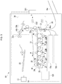
- FIG. 1 depicts an image forming apparatus 10 according to an embodiment.
- the image forming apparatus 10 includes a control panel 13, a wireless tag communication device 201, and a printer unit 18.
- the printer unit 18 includes an image forming controller 100, a sheet cassette 16a, and a sheet cassette 16b.
- the image forming controller 100 controls the control panel 13, the wireless tag communication device 201, and the printer unit 18.
- the image forming controller 100 controls conveyance of sheets in the printer unit 18. In particular, control of the conveyance of the sheets is to control the conveyance timing of a sheet, the stop position of a sheet, the conveyance speed of a sheet, and the like.
- the control panel 13 includes an input key and a display unit.
- the input key accepts input from a user.
- the display unit is a touch panel type.
- the display unit receives an input and displays the input.
- the control panel 13 displays an item of information related to the operation of the image forming apparatus 10 on the display unit so as to be able to set or adjust parameters or settings associated with the item.
- the control panel 13 notifies the image forming controller 100 of inputs and changes to settings made by the user.
- the sheet cassettes 16a and 16b store sheets on which a wireless tag is provided.
- the sheet cassettes 16a and 16b can also store sheets on which a wireless tag is not provided (e.g., a normal or standard sheet of paper or the like).
- references to a sheet refer to a sheet in or on which a wireless tag is provided.
- a material such as paper or a plastic film can be used as the sheet.
- the printer unit 18 performs operations for forming an image on the sheet. For example, the printer unit 18 prints an image corresponding to image data on a sheet. In the following description, forming an image on a sheet will also be referred to as "printing" .
- the printer unit 18 is a device for fixing a toner image to the sheets, but the present disclosure is not limited thereto, and the printer unit may be an ink jet type device or the like.
- the printer unit 18 includes an intermediate transfer belt 21.
- the printer unit 18 supports the belt 21 by the driven roller 41, the backup roller 40, and the like.
- the printer unit 18 rotates the intermediate transfer belt 21 in the direction indicated by the arrow m in Fig. 1 .
- the printer unit 18 includes four sets of image forming stations 22Y, 22M, 22C, and 22K.
- the image forming stations 22Y, 22M, 22C, and 22K correspond to Y (yellow), M (magenta), C (cyan), and K (black), respectively.
- the image forming stations 22Y, 22M, 22C and 22K are arranged on the lower side of the intermediate transfer belt 21 in order along the rotation direction of the intermediate transfer belt 21.
- the image forming station 22Y of Y (yellow) from among the image forming stations 22Y, 22M, 22C, and 22K will be described as an example.
- the image forming stations 22M, 22C and 22K have the same configuration as that of the image forming station 22Y, and therefore detailed description thereof will be omitted.
- the image forming station 22Y includes an electrostatic charger (charger) 26, an exposure scanning head 27, a developing device 28, and a photosensitive cleaner 29.
- the charger 26, the exposure scanning head 27, the developing device 28, and the cleaner 29 are disposed around the photosensitive drum 24 that rotates in the direction of the arrow n in Fig. 1 .
- the image forming station 22Y includes a first transfer roller 30.
- the first transfer roller 30 is disposed so as to face the photosensitive drum 24 via the intermediate transfer belt 21.
- the charger 26 uniformly charges the photosensitive drum 24.
- the exposure scanning head 27 selectively exposes the uniformly charged photosensitive drum 24 to form an electrostatic latent image on the photosensitive drum 24.
- the developing device 28 develops the electrostatic latent image on the photosensitive drum 24 by supplying a two-component developer (formed of a toner and a carrier) to the photosensitive drum 24.
- the first transfer roller 30 transfers the toner image formed on the photosensitive drum 24 to the intermediate transfer belt 21 (this may be referred to as a primary transfer).
- the first transfer roller 30 of each of the image forming stations 22Y, 22M, 22C, and 22K transfers the respective toner images onto the intermediate transfer belt 21, thereby forming a color toner image on the intermediate transfer belt 21.
- the color toner image is a toner image formed by sequentially supplying toner images of Y (yellow), M (magenta), C (cyan), and K (black).
- the cleaner 29 removes the toner remaining on the photosensitive drum 24 after the primary transfer.
- the printer unit 18 includes a second transfer roller 32.
- the second transfer roller 32 is disposed so as to face the backup roller 40 via the intermediate transfer belt 21.
- the second transfer roller 32 transfers the all of the color toner images on the intermediate transfer belt 21 to the sheet (this may be referred to as a secondary transfer).
- the term "toner image” may refer a multi-color toner image or a toner image of only one color (monochromatic).
- the toner image may be a toner image formed using a decolorable toner.
- the conveyance path 33 is a path through which a sheet is conveyed by conveyance rollers (for example, the conveyance rollers 330 and the like).
- the conveyance path 33 includes a first conveyance path 33a, a second conveyance path 33b, and a third conveyance path 33c.
- the first conveyance path 33a is a conveyance path from a merging portion 44a to a branch portion 44b.
- the second conveyance path 33b is a conveyance path passing through the inside of an inversion unit 38 (also referred to as a reversing unit), and is a conveyance path that is different from the branch portion 44b to the merging portion 44a and is different from the first conveyance path 33a.
- the third conveyance path 33c is a conveyance path from the branch portion 44b to a sheet discharge tray 20.
- the sheet to be processed can be taken out from any one of the sheet cassette 16a, the sheet cassette 16b, or a manual feeding tray 16c. After being taken out, the sheet is temporarily stopped at a portion where the two registration rollers 31 are in contact with each other. At this time, the leading edge of the sheet is brought into contact with the registration roller 31, and any inclination (angling) of the sheet edge is also corrected.
- the image forming controller 100 starts the rotation of the registration roller 31 in accordance with the expected position of the toner image on the rotating intermediate transfer belt 21, and thus moves the sheet to the position of the second transfer roller 32 at an appropriate timing to receive the toner image from the intermediate transfer belt.
- the toner image formed on the intermediate transfer belt 21 is secondarily transferred to the sheet at the second transfer roller 32. Subsequently, the transferred toner image is fixed to the sheet by a fixing device 34. In this way, an image is formed (printed) on the sheet under the control of the image forming controller 100.
- the image forming controller 100 then conveys the printed sheet to the third conveyance path 33c, and discharges the sheet.
- the wireless tag communication device 201 includes an arithmetic device, a storage device, and an antenna.
- the wireless tag in this example is a radio frequency identifier (RFID) tag.
- RFID radio frequency identifier
- the wireless tag communication device 201 transmits radio waves along the arrow k direction depicted in Fig. 1 .
- the wireless tag communication device 201 is able to communicate with a wireless tag provided in a sheet being conveyed. Specifically, the wireless tag communication device 201 reads information from the wireless tag and writes information to the wireless tag.
- the information written to the wireless tag includes, for example, information indicating a identification of the printed sheet/document, information indicating an intended destination of the sheet/document, and/or contents printed on the sheet/document for when the sheet is subsequently distributed or the like.
- the wireless tag communication device 201 uses, for example, a radio wave system (UHF) in the 900MHz band.
- UHF radio wave system
- the communication method/protocol and the frequency band are not limited, and other methods and frequency bands may be employed in other examples.
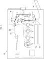
- FIG.2 is an explanatory diagram illustrating an example of double-sided printing.
- the sheet 250 is taken out from any one of sheet feeding locations, such as the sheet cassette 16a, the sheet cassette 16b, or the manual feeding tray 16c.
- the sheet 250 is then conveyed to the first conveyance path 33a. More specifically, the sheet 250 fed from one of the sheet feeding locations is corrected in inclination at the registration roller 31. Then, the sheet 250 is conveyed to the position of the second transfer roller 32 to match with the position of the toner image formed on the intermediate transfer belt 21.
- the toner image formed on the intermediate transfer belt 21 is transferred to the front side of the sheet 250 by the second transfer roller 32. Then, the toner image on the front side of the sheet 250 is fixed by the fixing device 34.
- the sheet 250 on which the image has been formed on the front side next enters the third conveyance path 33c. Then, under the control of the image forming controller 100, the sheet 250 is switched back and conveyed to the second conveyance path 33b. Thereafter, the sheet 250 is conveyed to the merging portion 44a via the second conveyance path 33b in the inversion unit 38. The sheet 250 is next conveyed to the first conveyance path 33a via the registration roller 31. Accordingly, the sheet 250 passing through the second conveyance path 33b is conveyed to the first conveyance path 33a so that the back surface side now faces toward the intermediate transfer belt 21 side.
- a toner image formed on the intermediate transfer belt 21 is transferred to the back surface side of the sheet 250 by the second transfer roller 32.
- the toner image transferred to the back surface side of the sheet 250 is fixed by the fixing device 34.
- the sheet 250 is supplied to the third conveyance path 33c, and is sent out to the sheet discharge tray 20.
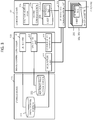
- FIG. 3 is a block diagram illustrating an example of a functional configuration of the sheet conveying apparatus 50 according to an embodiment.
- the sheet conveying apparatus 50 includes an image forming controller 100, a wireless tag communication device 201, a storage device 220, and a conveyance path 33.
- the image formation control unit 100 controls the wireless tag communication device 201 in accordance with a sheet conveyance program stored in the storage device 220.
- the image forming controller 100 is realized by, for example, a central processing unit (CPU), an application specific integrated circuit (ASIC), or the like.
- the storage device 220 is realized by a read only memory (ROM), a random access memory (RAM), a hard disk drive (HDD), a solid state drive (SSD), or the like.
- the wireless tag communication device 201 attempts to read an identification code (ID) of a wireless tag 251 (provided in a sheet 250) within a communication area at a certain, fixed interval (for example, at a 10msec interval). Specifically, the wireless tag communication device 201 transmits a signal (carrier wave) at a predetermined interval. When a wireless tag 251 in the communication area receives a signal from the wireless tag communication device 201, the wireless tag 251 receives electric power from this signal and starts up.
- the wireless tag communication device 201 can be a wireless tag reader/writer device. Then, the wireless tag 251 transmits a response wave including the ID of the wireless tag communication device 201 previously written or otherwise stored in the wireless tag 251. Accordingly, the wireless tag communication device 201 receives a response wave from the wireless tag 251 and acquires the ID data corresponding to the wireless tag 251 ID.
- the wireless tag communication device 201 is capable of communicating with the image forming controller 100.
- the wireless tag communication device 201 receives a response wave from the wireless tag 251 provided in the sheet 250 at regular intervals, and transmits phase data indicating the phase of the received response wave to the image formation controller 100.
- the image forming controller 100 includes an acquisition unit 101, a detect unit 102, a specifying unit 103, and a communication controller 104.
- the respective units 101 to 104 are not limited to being provided within the image forming controller 100, and may be provided in another control unit (another CPU, an ASIC, or the like) different from the image forming controller 100.
- the acquisition unit 101 acquires the phase data of the response wave received from the wireless tag 251 by the wireless tag communication device 201. More specifically, the acquisition unit 101 acquires the phase data of the response wave from the wireless tag communication device 201 at a certain interval (for example, at a 10msec interval). The acquisition unit 101 starts acquisition of the phase data every time a sheet 250 begins to be printed.
- the acquisition unit 101 stores the acquired phase data of the response waves in a phase storage portion 221 of the storage device 220 for each interval (for example, at a 10msec interval).
- the sheet 250 more particularly, the wireless tag 251 of the sheet 250
- the phase of the response wave from the wireless tag 251 changes.
- the response wave from a sheet 250 (the wireless tag 251 therein) moving on the first conveyance path 33a tends to change according to a common change pattern of specific phases.
- a sheet 250 (wireless tag 251) is not moved, the phase of the response wave from the wireless tag does not change substantially.
- the information can be written to the wireless tag 251 while the sheet 250 is moving through the conveyance path 33. Therefore, the communication area of the wireless tag communication device 201 needs to be set relatively wide. More specifically, the communication area of the wireless tag communication device 201 is a wider than would be the case if the sheet 250 could be completely stopped and information written to the wireless tag 251 only while the sheet is stationary at a specific location. For this reason, if information is to be written to the wireless tag 251 while the sheet 250 is moving along the conveyance path 33, the potential for information to be inadvertently written to another wireless tag 251 within the communication area instead of the intended target wireless tag 251 to which the information is to be written increases.
- the detect unit 102 refers to the phase data stored in the phase storage portion 221, and detects a phase change amount of the response wave acquired from wireless tags 251 within the communication area at regular intervals.
- the phase change amount is, for example, a value indicating a difference in phase acquired at a different times from an initial, previous, or reference time. More specifically, in this example, the phase change amount is a difference between the response wave phases stored at a timing interval of 10msec.
- the specifying unit 103 identifies a wireless tag 251 to be read/written (hereinafter referred to as a "target wireless tag 251a") based on the amount of phase change of the response wave detected by the detect unit 102. Specifically, when the phase change amount of the response wave is equal to or larger than some predetermined value (for example, 10°), the specifying unit 103 specifies the wireless tag 251 for which such a phase change amount is obtained as the target wireless tag 251a.
- some predetermined value for example, 10°
- a wireless tag 251 (the target wireless tag 251a) for which the phase change amount of the response wave is equal to or more than the predetermined value is considered to be on a sheet 250 is being moved along some portion of the conveyance path 33 (for example, the first conveyance path 33a). Accordingly, the specifying unit 103 can identify the wireless tag 251 being moved as the target wireless tag 251a.
- the communication controller 104 controls the wireless tag communication device 201 so as to write information to the target wireless tag 251a as specified by the specifying unit 103.
- the wireless tag communication device 201 writes information to the target wireless tag 251a in accordance with the control of the communication controller 104.
- a reference value storage portion 222 stores in advance a reference value of the phase of the response wave when the sheet 250 moves on the conveyance path (hereinafter referred to as a "phase reference value").
- the phase reference value is a change pattern (reference pattern) of the phase of the response wave associated with the normal conveyance of a sheet 250.
- the reference pattern is, for example, a change pattern that increases by 20° for each 10msec.
- the phase reference value can be obtained by conveying one test sheet 250 in an environment in which other wireless tags 251 are not present around the sheet.
- phase reference value(s) can be provided before shipment of the image forming apparatus 10 from a factory or the like.
- the phase reference value is, for example, a value that can be different for different image forming apparatuses 10.
- the phase reference value is not necessarily required to be a factory setting, and for example, the phase reference value may be obtained by prompting a user to obtain a reference value by operation of the image forming apparatus 10 during a user setup mode or the like.
- the specifying unit 103 identifies the target wireless tag 251a based on the result of the comparison between the phase change amount detected by the detect unit 102 and the phase reference value stored in the reference value storage portion 222. Specifically, for example, the specifying unit 103 compares the change pattern indicated by the phase change amount detected by the detect unit 102 with the reference pattern stored in the reference value storage portion 222. As a result of the comparison, the specifying unit 103 is able to identify a particular wireless tag 251 that has output a response wave corresponding to the phase reference pattern as the target wireless tag 251a when the detected and reference patterns are approximately the same.
- the specifying unit 103 identifies a non-target wireless tag 251 (hereinafter referred to as a "non-target wireless tag 251b") that is not a target for reading and writing, based on the phase change amount detected by the detect unit 102.
- the non-target wireless tag 251b is, for example, a wireless tag 251 provided in a sheet 250 still in the sheet cassettes 16a, 16b, or on the manual feed tray 16c.
- the communication controller 104 requests the non-target wireless tag 251b specified by the specifying unit 103 to suppress the output of response waves. More specifically, the communication controller 104 controls the wireless tag communication device 201 to transmit a response suppression command to the non-target wireless tag 251b for suppressing the output of response waves. In response to this response suppression command, the non-target wireless tag 251b turns on a response suppression flag for prevent the output of a response wave from the non-target wireless tag 251b until subsequent commands.
- the response suppression flag can be reset by cutting off the output of radio waves from the wireless tag communication device 201.
- the output of radio waves from the wireless tag communication device 201 is thus cut every time a new printing of a sheet 250 is to be performed.
- the response suppression flag can be reset every time the printing of a sheet 250 is performed.
- the position at which the information is written to the target wireless tag 251a may be set to be on the first conveyance path 33a, but in the present embodiment, this position is on the second conveyance path 33b.
- the conveyance path 33 includes a first conveyance path 33a, a second conveyance path 33b, and a third conveyance path 33c, which may be considered portions and/or branches of the overall conveyance path 33.
- the first conveyance path 33a is the portion of the conveyance path 33 used for forming an image on a sheet 250.
- the first conveyance path 33a can be used for performing a front surface printing on a sheet 250 fed directly from one the cassettes 16a, 16b, but may also be used for a back surface printing on a sheet 250 returned via the inversion unit 38.
- the second conveyance path 33b is the path by which a sheet 250 is returned through the inversion unit 38 after previously passing through the first conveyance path 33a.
- the second conveyance path 33b is a position closer to the wireless tag communication device 201 than is the first conveyance path 33a.
- the detect unit 102 is used to detect the phase change amount in the response wave from sheets 250 traveling along the first conveyance path 33a.
- the specifying unit 103 identifies a target wireless tag 251a based on the phase change amount(s) detected by the detect unit 102.
- the communication controller 104 controls the wireless tag communication device 201 to write the information to the target wireless tag 251a when the target wireless tag 251a identified by the specifying unit 103 moves to the second conveyance path 33b.
- the communication controller 104 determines whether or not the sheet 250 with the target wireless tag 251a has moved to the second conveyance path 33b.
- the communication controller 104 may determine that the sheet 250 with the target wireless tag 251a has moved to the second conveyance path 33b based on, for example, the timing of switching functions along the conveyance path 33 for switch back (inversion) processing.
- the sheet 250 on the second conveyance path 33b is subsequently returned to the first conveyance path 33a again.
- backside printing second printing
- the backside printing is performed.
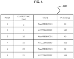
- FIG. 4 is an explanatory diagram illustrating an example of phase data stored in the phase storage portion 221.
- phase data 400 includes items corresponding to an "Index”, an "elapsed time”, a “tag ID”, and a "Phase”.
- Index items are information (e.g. an index number or a counting value) for identifying each piece of data.
- the "elapsed time” is the elapsed time since the start of a printing operation corresponding to when the particular tag ID and phase value were detected. For example, the time elapsed since the wireless tag communication device 201 transmits the first signal (carrier wave) in the printing operation can be used as the elapsed time value.
- the "tag ID” value is unique identification information allocated for each of the different wireless tags 251. In this context, "Phase” information indicates a detect phase value (0° to 180°) for a response wave.
- phase data 400 depicted in FIG. 4 wireless tags 251 two different “tag IDs", “AAAABBBB0001” and “CCCCDDDD0002,” are illustrated. That is, FIG. 4 shows that two different “tag IDs” corresponding to two different the wireless tags 251 are in the communication area. When there are 3 or more types of "tag IDs" in the communication area of the wireless tag communication device 201.
- the phase data 400 can include "tag IDs" corresponding to any number of wireless tags 251 detected in the communication area, but here only two different tags 251 are represented in FIG. 4 .
- phase change amount of the wireless tag 251 having the tag ID "AAAABBBB0001” will be described.
- the "Phase” of the response wave of the wireless tag 251 with the tag ID "AAAABBBB0001” at elapsed time of 0 msec is 20°.
- the “Phase” of the response wave of the wireless tag 251 with the tag ID "AAAABBBB0001” at 10 msec is 40°.
- the phase change amount for the response wave of the wireless tag 251 with the tag ID AAAABBBB0001 is +20° from 0 msec to 10 msec.
- This phase change amount (magnitude change) is equal to or larger than a predetermined value (for example, 10°) indicating travel/movement of the wireless tag 251.
- the "Phase” of the response wave of the wireless tag 251 with the tag ID "AAAABBBB0001" at the 20 msec is 60°.
- the phase change amount of the response wave of the wireless tag 251 with the tag ID "AAAABBBB0001” from 10 msec to 20 msec is again +20° (magnitude change of 20°).
- the phase change amount is again equal to or larger than the predetermined value (for example, 10°). That is, the wireless tag 251 ("AAAABBBB0001") is estimated to be a wireless tag 251 on a sheet 250 being moved.
- the comparison between the phase change amount and the predetermined value is, for example, a comparison of absolute values.
- the phase change pattern obtained from the phase change amounts over time for a particular wireless tag 251 can be compared to a reference pattern stored in the reference value storage portion 222, for example.
- the specifying unit 103 identifies the wireless tag 251 having the tag ID "AAAABBBB0001" as target wireless tag 251a.
- phase change amount of the wireless tag 251 having the tag ID "CCCCDDDD0002” will be described.
- value “2" in the "Index” column the “Phase” of the response wave of the wireless tag 251 with the tag ID “CCCCDDDD0002” at 1 msec is 162°.
- value “4" in the "Index” column the “Phase” of the response wave of the wireless tag 251 with the tag ID "CCCCDDDD0002” at 11 msec is 161°. Therefore, the phase change amount of the response wave of the wireless tag 251 with the tag ID "CCCCDDDD0002" from 1 msec to 11 msec is -1° (the absolute size change is 1°). This amount of phase change is less than the predetermined value (for example, 10°).
- the "Phase” of the wireless tag 251 with the tag ID "CCCCDDDD0002" at the 21 msec is 163 degrees.
- the amount of phase change in the response wave of the wireless tag 251 with the tag ID "CCCCDDDD0002” from 11 msec to 21 msec is +2° (the absolute size is 2°).
- the amount of phase change is less than the predetermined value (for example, 10°).
- the difference in the detected phase change amount is presumably due to a minor error in measurement or the like. That is, it can be considered that there has been almost no change in the phase change amount for the wireless tag 251 with the tag ID "CCCCDDDD0002".
- the specifying unit 103 identifies the wireless tag 251 having the tag ID "CCCCDDDD0002" as the non-target wireless tag 251b.
- FIG. 5 is a flowchart illustrating an example of a process related to reading and writing of information with respect to the wireless tags 251 as performed by the image forming apparatus 10.
- the image forming apparatus 10 determines whether a printing has been started (ACT501).
- the printing in this context is, for example, a printing on a single sheet 250.
- the image forming apparatus 10 waits (ACT501: NO) until the start of printing.
- the image forming apparatus 10 starts RFID reading (ACT502).
- the image forming controller 100 controls the wireless tag communication device 201 to start transmission of a carrier wave signal at regular intervals, and begins reception of any response wave(s).
- the image forming apparatus 10 determines whether or not the wireless tag 251 has been detected (ACT503).
- the image forming controller 100 determines whether or not the wireless tag communication device 201 has received a response wave from a wireless tag 251.
- the image forming apparatus 10 stands by (ACT503: NO).
- the image forming apparatus 10 stores the relevant data items (that is, values for the "elapsed time", "tag ID”, and "Phase ") of the phase data 400 as obtained by receiving the response wave from a wireless tag 251.
- the image forming apparatus 10 detects, measures, or calculates the phase change amount for a wireless tag 251 indicated by a previously received tag ID (ACT505) if available. Then, the image forming apparatus 10 determines whether or not the phase change amount is equal to or larger than some predetermined value (ACT506). When the phase change amount is equal to or larger than the predetermined value (ACT506: YES), the image forming apparatus 10 proceeds to ACT508. When the phase change amount is not equal to or larger than the predetermined value (ACT506: NO), the image forming apparatus 10 controls the wireless tag communication device 201 to transmit a response suppression command addressed to the particular (estimated as none moving) wireless tag 251 (ACT507), and returns to ACT503.
- the image forming apparatus 10 compares the phase change pattern for a particular wireless tag estimated as possibly moving in the prior step(s) with the reference pattern stored in the reference value storage portion 222 (ACT508). Next, the image forming apparatus 10 determines whether or not the phase change pattern matches, or substantially coincides with, the reference pattern (ACT509). When the phase change pattern does not match the reference pattern (ACT509: NO), the image forming apparatus 10 returns to ACT507.
- the image forming apparatus 10 next determines whether or not the sheet 250 having the wireless tag 251 has been passed to the second conveyance path 33b (ACT510).
- a sheet 250 passing through the second conveyance path 33b can be determined, for example, by detecting that the entire sheet 250 has passed the branch portion 44b and being conveyed to the second conveyance path 33b by switching back the sheet 250.
- the image forming apparatus 10 waits until the sheet 250 is on the second conveyance path 33b (ACT510: NO). When the sheet 250 is deemed on the second conveyance path 33b (ACT510: YES), the image forming apparatus 10 controls the wireless tag communication device 201 to write information to the wireless tag 251 (ACT511).
- the image forming apparatus 10 determines whether or not the printing is finished (ACT512). The image forming apparatus 10 stands by until the printing is completed (ACT512: NO). Once the printing is finished (ACT512: YES), the image forming apparatus 10 controls the wireless tag communication device 201 to reset the communication with the wireless tags 251 (ACT513), and ends the present series of processes.
- the outputting of radio waves from previously suppressed wireless tags 251 is reset since the response suppression flag in any of the wireless tags 251 is reset.
- the collected phase data 400 can also be reset by the reset of the communication with the wireless tag 251.
- the processing of the ACT506 determination of the amount of phase change
- the processing of the ACT508 and ACT509 the comparison of the change pattern to a reference pattern
- the processing is not limited to this.
- the processes may be performed together or just one of the processes may be performed.
- the wireless tag communication device 201 can be controlled so that the target wireless tag 251a is first identified based on the phase change amount of the response wave and then the information is written to the target wireless tag 251a. Accordingly, the sheet conveyance device 50 can appropriately write information to the intended wireless tag 251 of a sheet 250 actually moving on the conveyance path 33. That is, erroneous (unintended) writing of information to a wireless tag 251 of a sheet 250 in the sheet cassettes 16a, 16b, or on the manual feed tray 16c can be avoided.
- the sheet conveyance apparatus 50 specifies the target wireless tag 251a based on a result of the comparison between the phase change pattern of the response wave output from the wireless tag 251 and a reference pattern for the phase of the response wave of a sheet 250 moved on the conveyance path 33. Accordingly, it is possible to more accurately identify a sheet 250 moving on the conveyance path 33, and thus it is possible to more appropriately write information to the wireless tag 251 of the sheet 250 that moves on the conveyance path 33.
- the sheet conveyance device 50 specifies the non-target wireless tag(s) 251b on the basis of the phase change amount of the response wave output from the wireless tag 251, and controls the non-target wireless tag(s) 251b to suppress the output of a response wave. Accordingly, it is possible to prevent a response wave from being output from the wireless tag 251 that is not required.
- the wireless tag communication device 201 receives a response wave from a wireless tag 251 that is not targeted for writing, an operation of reading the ID of the wireless tag 251 is still performed accordingly, and the operation of reading the ID of a wireless tag 251 may still require an interval longer than, for example, 10 msec to perform associated processing.
- the present embodiment it is possible to suppress the output of the unnecessary response wave from the untargeted wireless tags 251, and therefore, it is possible to prevent unnecessary operations associated with reading the ID of such wireless tags 251.
- the sheet conveyance device 50 specifies the non-target wireless tag 251b based on the phase change amount of the response wave while on the first conveyance path 33a, and then writes the information to the wireless tag 251 when the sheet 250 moves to the second conveyance path 33b. Accordingly, it is possible to secure a period for detecting the phase change amount of the response wave on the first conveyance path 33a. That is, it is possible to appropriately detect the phase change amount of the response wave. Therefore, it is possible to more accurately determine that a particular sheet 250 is moving on the conveyance path 33. In addition, it is possible to secure a period in which information is written to the wireless tag 251 when on the second conveyance path 33b. Therefore, it is possible to appropriately write information to the wireless tag 251 of the sheet 250 while on the second conveyance path 33b.
- the first conveyance path 33a is first used for performing front surface printing
- the second conveyance path 33b is used for performing the back surface printing (that is, the conveyance path 33b is the sheet reversing or return path).
- the second conveyance path 33b is at a position closer to the wireless tag communication device 201 than the first conveyance path 33a. Accordingly, it is possible to shorten the communication distance to the wireless tag 251, and thus it is possible to more appropriately write the information to the wireless tag 251 of the sheet 250 on the second conveyance path 33b.
- the function(s) of a sheet conveying apparatus 50 in the above-described embodiment may be realized by a computer.
- a program for realizing the function(s) may be recorded in a non-transitory, computer-readable recording medium, and the program recorded in the recording medium may be loaded into a computer system and then executed by the computer system.
- a "computer system” includes, for example, an operating system, hardware, a peripheral device, and the like.
- a "computer-readable recording medium” refers to a portable medium such as a flexible disk, a magneto-optical disk, a ROM, or a CD-ROM, and a storage device such as a hard disk built in the computer system.
- the "computer-readable recording medium” may include a cloud-based storage system or the like and a program can be transmitted via a network such as the Internet or a communication line such as a telephone line from a computer system serving as a server or a client.
- the program may be a program for realizing a part of the functions described above or may be a program for realizing the above-described functions in combination with a program already recorded in the computer system.
Landscapes
- Engineering & Computer Science (AREA)
- Physics & Mathematics (AREA)
- General Physics & Mathematics (AREA)
- Multimedia (AREA)
- Signal Processing (AREA)
- Theoretical Computer Science (AREA)
- Microelectronics & Electronic Packaging (AREA)
- Control Or Security For Electrophotography (AREA)
- Controlling Sheets Or Webs (AREA)
- Near-Field Transmission Systems (AREA)
- Accessory Devices And Overall Control Thereof (AREA)
Abstract
Description
- This application is based upon and claims the benefit of priority from Japanese Patent Application No.
2020-011484, filed on January 28, 2020 - Embodiments described herein relate generally to a sheet conveying apparatus and a program.
- Conventionally, an image forming apparatus conveys a sheet from a sheet cassette or a manual feeding tray and then forms an image on the conveyed sheet. In some examples, sheets of a certain type incorporate a wireless tag (e.g., an RFID tag). In order to read and write information to and from a wireless tag of such a sheet, the image forming apparatus incorporates a wireless tag communication device along the sheet conveyance path.
- A technique of performing reading and writing to tags while the resonance frequency of the transmission antenna is changed such that the frequency deviation between the resonance frequency of the transmission antenna and the transmission signal being supplied to the transmission antenna falls within an allowable range in order to prevent the deterioration in the antenna communication performance due to a decrease in the resonance current is known.
- However, if information is to be written to a wireless tag of a sheet while moving on a conveyance path, the communication area of the wireless tag communication apparatus becomes relatively wide. As such, the wireless tag communication device may also inadvertently communicate with other wireless tags on the sheet or on the conveyance path, and may thus write information to these other wireless tags in error. For example, the wireless tag communication device may inadvertently write information to a wireless tag on a sheet that is not yet on the conveyance path, such as a sheet still in a sheet cassette.
- One of the objects of the present invention is to improve prior art techniques and overcome at least some of the prior art problems as for instance above illustrated.
- According to a first aspect of the present invention, it is provided a sheet conveying apparatus, comprising a conveyance path along which a sheet can be conveyed; a plurality of conveyance rollers configured to move a sheet along the conveyance path; a wireless tag reader/writer configured to read information from, and write information to, a wireless tag of a sheet on the conveyance path; a phase change detector configured to detect a phase change in response waves received by the wireless tag reader/writer from a wireless tag; a tag specifying unit configured to identify whether a wireless tag is moving along the conveyance path based on the detected phase change in response waves from the wireless tag; and a controller configured to control the wireless tag reader/writer to write information to the wireless tag identified as moving along the conveyance path.
- Optionally, in the sheet conveying apparatus according to the first aspect of the invention, the tag specifying unit is configured to identify whether the wireless tag is moving along the conveyance path by comparison of the detected phase change in response waves from the wireless tag to a previously stored reference pattern corresponding to phase changes in response waves for a wireless tag moving along the conveyance path.
- Optionally, in the sheet conveying apparatus according to the first aspect of the invention, the tag specifying unit is configured to identify a wireless tag that is not moving along the conveyance path by a lack of phase change in response waves from the wireless tag over intervals of time.
- Optionally, in the sheet conveying apparatus according to the first aspect of the invention, the wireless tag reader/writer is configured to output a response suppression signal addressed to the wireless tag identified by the tag specifying unit as not moving along the conveyance path.
- Optionally, in the sheet conveying apparatus according to the first aspect of the invention, the conveyance path comprises a first portion along which an image is transferred to the sheet in a printing operation, and a second portion along which the sheet travels to be returned to the first portion.
- Optionally, in the sheet conveying apparatus according to the first aspect of the invention, the second portion is closer to the wireless tag reader/writer than is the first portion.
- Optionally, in the sheet conveying apparatus according to the first aspect of the invention, the controller is configured to cause the wireless tag reader/writer to write information to an identified wireless tag while the identified tag is on the second portion of the conveyance path.
- Optionally, in the sheet conveying apparatus according to the first aspect of the invention, the wireless tag is an RFID tag.
- According to a second aspect of the invention, it is provided an image forming apparatus, comprising a first conveyance path portion along which a sheet can be conveyed past a transfer roller at which an image can be transferred to a surface of the sheet; a second conveyance path portion along which a sheet from the first conveyance path portion can be returned to the first conveyance path portion for an image to be transferred to another surface of the sheet; a wireless tag reader/writer configured to read information from and write information to a wireless tag of a sheet in the image forming apparatus; a phase change detector configured to detect a phase change in response waves received by the wireless tag reader/writer from a wireless tag; a tag specifying unit configured to identify whether a wireless tag is moving along the first conveyance path portion based on the detected phase change in response waves from the wireless tag; and a controller configured to control the wireless tag reader/writer to write information to the identified wireless tag while the wireless tag is moving along the second conveyance path portion.
- Optionally, in the image forming apparatus according to the second aspect of the invention, the tag specifying unit is configured to identify whether the wireless tag is moving along the first conveyance path portion by comparison of the detected phase change in response waves from the wireless tag to a previously stored reference pattern corresponding to phase changes in response waves for a wireless tag moving along the first conveyance path portion.
- Optionally, in the image forming apparatus according to the second aspect of the invention, the tag specifying unit is configured to identify a wireless tag that is not moving along the first or second conveyance path portion by a lack of phase change in response waves from the wireless tag over intervals of time.
- Optionally, in the image forming apparatus according to the second aspect of the invention, the wireless tag reader/writer is configured to output a response suppression signal addressed to the wireless tag identified by the tag specifying unit as not moving along the first or second conveyance path portion.
- Optionally, in the image forming apparatus according to the second aspect of the invention, the second conveyance path portion is closer to the wireless tag reader/writer than is the first conveyance path portion.
- Optionally, in the image forming apparatus according to the second aspect of the invention, the wireless tag is an RFID tag.
- According to a third aspect of the invention, it is provided a non-transitory computer-readable recording medium storing therein a program causing a sheet conveying apparatus to perform a method comprising convey a sheet including a wireless tag along a conveyance path; read information from the wireless tag of the sheet being conveyed along the conveyance path using a wireless tag reader/writer; detect a phase change in response waves received from the wireless tag by the wireless tag reader/writer; identify whether the wireless tag is moving along the conveyance path based on the detected phase change in response waves from the wireless tag; and cause the wireless tag reader/writer to write information to the wireless tag identified as moving along the conveyance path.
- Optionally, in the non-transitory computer-readable recording medium according to the third aspect of the invention, the method further comprising identifying whether the wireless tag is moving along the conveyance path by comparison of the detected phase change in response waves from the wireless tag to a previously stored reference pattern corresponding to phase changes in response waves for a wireless tag moving along the conveyance path.
- Optionally, in the non-transitory computer-readable recording medium according to the third aspect of the invention, the method further comprising causing the wireless tag reader/writer to output a response suppression signal addressed to any wireless tag identified as not moving along the conveyance path.
- Optionally, in the non-transitory computer-readable recording medium according to the third aspect of the invention, the conveyance path comprises a first portion along which an image is transferred to the sheet in a printing operation, and a second portion along which the sheet travels to be returned to the first portion.
- Optionally, in the non-transitory computer-readable recording medium according to the third aspect of the invention, the method further comprising causing the wireless tag reader/writer to write information to an identified wireless tag while the identified tag is on the second portion of the conveyance path.
- Optionally, in the non-transitory computer-readable recording medium according to the third aspect of the invention, the wireless tag is an RFID tag.
-
-
FIG. 1 is schematic diagram of an image forming apparatus according to an embodiment. -
FIG. 2 is an schematic diagram of a sheet flow for double-sided printing. -
FIG. 3 is a block diagram of a sheet conveying apparatus according to an embodiment. -
FIG. 4 is an schematic diagram depicting phase data stored in a phase storage portion. -
FIG. 5 is a flowchart of a process related to reading and writing of information from and to a wireless tag. - According to an embodiment, a sheet conveying apparatus of an embodiment comprises a conveyance path along which a sheet can be conveyed, and a plurality of conveyance rollers configured to move a sheet along the conveyance path. A wireless tag reader/writer is configured to read information from, and write information to, a wireless tag of a sheet on the conveyance path. A phase change detector is configured to detect a phase change in response waves received by the wireless tag reader/writer from a wireless tag. A tag specifying unit is configured to identify whether a wireless tag is moving along the conveyance path based on the detected phase change in response waves from the wireless tag. A controller is configured to control the wireless tag reader/writer to write information to the wireless tag identified as moving along the conveyance path.
- A sheet conveyance apparatus of an embodiment can appropriately write information to a wireless tag on a sheet that is being moved along a conveyance path. Hereinafter, an image forming apparatus incorporating a sheet conveying apparatus according to an embodiment will be described as an example.
- First, a configuration of the
image forming apparatus 10 according to an embodiment will be described with reference toFIG. 1. FIG. 1 depicts animage forming apparatus 10 according to an embodiment. - In
FIG. 1 , theimage forming apparatus 10 includes acontrol panel 13, a wirelesstag communication device 201, and aprinter unit 18. Theprinter unit 18 includes animage forming controller 100, asheet cassette 16a, and asheet cassette 16b. Theimage forming controller 100 controls thecontrol panel 13, the wirelesstag communication device 201, and theprinter unit 18. Theimage forming controller 100 controls conveyance of sheets in theprinter unit 18. In particular, control of the conveyance of the sheets is to control the conveyance timing of a sheet, the stop position of a sheet, the conveyance speed of a sheet, and the like. - The
control panel 13 includes an input key and a display unit. For example, the input key accepts input from a user. For example, the display unit is a touch panel type. The display unit receives an input and displays the input. For example, thecontrol panel 13 displays an item of information related to the operation of theimage forming apparatus 10 on the display unit so as to be able to set or adjust parameters or settings associated with the item. Thecontrol panel 13 notifies theimage forming controller 100 of inputs and changes to settings made by the user. - The
sheet cassettes sheet cassettes - The
printer unit 18 performs operations for forming an image on the sheet. For example, theprinter unit 18 prints an image corresponding to image data on a sheet. In the following description, forming an image on a sheet will also be referred to as "printing" . In the present embodiment, theprinter unit 18 is a device for fixing a toner image to the sheets, but the present disclosure is not limited thereto, and the printer unit may be an ink jet type device or the like. - In this example, the
printer unit 18 includes anintermediate transfer belt 21. Theprinter unit 18 supports thebelt 21 by the drivenroller 41, thebackup roller 40, and the like. Theprinter unit 18 rotates theintermediate transfer belt 21 in the direction indicated by the arrow m inFig. 1 . Theprinter unit 18 includes four sets ofimage forming stations image forming stations image forming stations intermediate transfer belt 21 in order along the rotation direction of theintermediate transfer belt 21. - Hereinafter, the
image forming station 22Y of Y (yellow) from among theimage forming stations image forming stations image forming station 22Y, and therefore detailed description thereof will be omitted. - The
image forming station 22Y includes an electrostatic charger (charger) 26, anexposure scanning head 27, a developingdevice 28, and aphotosensitive cleaner 29. Thecharger 26, theexposure scanning head 27, the developingdevice 28, and the cleaner 29 are disposed around thephotosensitive drum 24 that rotates in the direction of the arrow n inFig. 1 . - The
image forming station 22Y includes afirst transfer roller 30. Thefirst transfer roller 30 is disposed so as to face thephotosensitive drum 24 via theintermediate transfer belt 21. - The
charger 26 uniformly charges thephotosensitive drum 24. Theexposure scanning head 27 selectively exposes the uniformly chargedphotosensitive drum 24 to form an electrostatic latent image on thephotosensitive drum 24. The developingdevice 28 develops the electrostatic latent image on thephotosensitive drum 24 by supplying a two-component developer (formed of a toner and a carrier) to thephotosensitive drum 24. - The
first transfer roller 30 transfers the toner image formed on thephotosensitive drum 24 to the intermediate transfer belt 21 (this may be referred to as a primary transfer). Thefirst transfer roller 30 of each of theimage forming stations intermediate transfer belt 21, thereby forming a color toner image on theintermediate transfer belt 21. The color toner image is a toner image formed by sequentially supplying toner images of Y (yellow), M (magenta), C (cyan), and K (black). The cleaner 29 removes the toner remaining on thephotosensitive drum 24 after the primary transfer. - The
printer unit 18 includes asecond transfer roller 32. Thesecond transfer roller 32 is disposed so as to face thebackup roller 40 via theintermediate transfer belt 21. Thesecond transfer roller 32 transfers the all of the color toner images on theintermediate transfer belt 21 to the sheet (this may be referred to as a secondary transfer). In the following description, the term "toner image" may refer a multi-color toner image or a toner image of only one color (monochromatic). The toner image may be a toner image formed using a decolorable toner. - The
conveyance path 33 is a path through which a sheet is conveyed by conveyance rollers (for example, theconveyance rollers 330 and the like). In this example, theconveyance path 33 includes afirst conveyance path 33a, asecond conveyance path 33b, and athird conveyance path 33c. Thefirst conveyance path 33a is a conveyance path from a mergingportion 44a to abranch portion 44b. Thesecond conveyance path 33b is a conveyance path passing through the inside of an inversion unit 38 (also referred to as a reversing unit), and is a conveyance path that is different from thebranch portion 44b to the mergingportion 44a and is different from thefirst conveyance path 33a. Thethird conveyance path 33c is a conveyance path from thebranch portion 44b to asheet discharge tray 20. - The sheet to be processed can be taken out from any one of the
sheet cassette 16a, thesheet cassette 16b, or amanual feeding tray 16c. After being taken out, the sheet is temporarily stopped at a portion where the tworegistration rollers 31 are in contact with each other. At this time, the leading edge of the sheet is brought into contact with theregistration roller 31, and any inclination (angling) of the sheet edge is also corrected. Theimage forming controller 100 starts the rotation of theregistration roller 31 in accordance with the expected position of the toner image on the rotatingintermediate transfer belt 21, and thus moves the sheet to the position of thesecond transfer roller 32 at an appropriate timing to receive the toner image from the intermediate transfer belt. - That is, the toner image formed on the
intermediate transfer belt 21 is secondarily transferred to the sheet at thesecond transfer roller 32. Subsequently, the transferred toner image is fixed to the sheet by a fixingdevice 34. In this way, an image is formed (printed) on the sheet under the control of theimage forming controller 100. Theimage forming controller 100 then conveys the printed sheet to thethird conveyance path 33c, and discharges the sheet. - The wireless
tag communication device 201 includes an arithmetic device, a storage device, and an antenna. The wireless tag in this example, is a radio frequency identifier (RFID) tag. The wirelesstag communication device 201 transmits radio waves along the arrow k direction depicted inFig. 1 . The wirelesstag communication device 201 is able to communicate with a wireless tag provided in a sheet being conveyed. Specifically, the wirelesstag communication device 201 reads information from the wireless tag and writes information to the wireless tag. - The information written to the wireless tag includes, for example, information indicating a identification of the printed sheet/document, information indicating an intended destination of the sheet/document, and/or contents printed on the sheet/document for when the sheet is subsequently distributed or the like. In the present embodiment, the wireless
tag communication device 201 uses, for example, a radio wave system (UHF) in the 900MHz band. However, the communication method/protocol and the frequency band are not limited, and other methods and frequency bands may be employed in other examples. - Next, double-sided printing operations will be described.
-
FIG.2 is an explanatory diagram illustrating an example of double-sided printing. - In the case of the double-sided printing, the
sheet 250 is taken out from any one of sheet feeding locations, such as thesheet cassette 16a, thesheet cassette 16b, or themanual feeding tray 16c. Thesheet 250 is then conveyed to thefirst conveyance path 33a. More specifically, thesheet 250 fed from one of the sheet feeding locations is corrected in inclination at theregistration roller 31. Then, thesheet 250 is conveyed to the position of thesecond transfer roller 32 to match with the position of the toner image formed on theintermediate transfer belt 21. The toner image formed on theintermediate transfer belt 21 is transferred to the front side of thesheet 250 by thesecond transfer roller 32. Then, the toner image on the front side of thesheet 250 is fixed by the fixingdevice 34. - The
sheet 250 on which the image has been formed on the front side next enters thethird conveyance path 33c. Then, under the control of theimage forming controller 100, thesheet 250 is switched back and conveyed to thesecond conveyance path 33b. Thereafter, thesheet 250 is conveyed to the mergingportion 44a via thesecond conveyance path 33b in theinversion unit 38. Thesheet 250 is next conveyed to thefirst conveyance path 33a via theregistration roller 31. Accordingly, thesheet 250 passing through thesecond conveyance path 33b is conveyed to thefirst conveyance path 33a so that the back surface side now faces toward theintermediate transfer belt 21 side. - Then, a toner image formed on the
intermediate transfer belt 21 is transferred to the back surface side of thesheet 250 by thesecond transfer roller 32. The toner image transferred to the back surface side of thesheet 250 is fixed by the fixingdevice 34. Then, thesheet 250 is supplied to thethird conveyance path 33c, and is sent out to thesheet discharge tray 20. - Next, a sheet conveying apparatus 50 included in the
image forming apparatus 10 will be described with reference toFIG. 3. FIG. 3 is a block diagram illustrating an example of a functional configuration of the sheet conveying apparatus 50 according to an embodiment. - In
FIG. 3 , the sheet conveying apparatus 50 includes animage forming controller 100, a wirelesstag communication device 201, astorage device 220, and aconveyance path 33. The imageformation control unit 100 controls the wirelesstag communication device 201 in accordance with a sheet conveyance program stored in thestorage device 220. - The
image forming controller 100 is realized by, for example, a central processing unit (CPU), an application specific integrated circuit (ASIC), or the like. Thestorage device 220 is realized by a read only memory (ROM), a random access memory (RAM), a hard disk drive (HDD), a solid state drive (SSD), or the like. - The wireless
tag communication device 201 attempts to read an identification code (ID) of a wireless tag 251 (provided in a sheet 250) within a communication area at a certain, fixed interval (for example, at a 10msec interval). Specifically, the wirelesstag communication device 201 transmits a signal (carrier wave) at a predetermined interval. When awireless tag 251 in the communication area receives a signal from the wirelesstag communication device 201, thewireless tag 251 receives electric power from this signal and starts up. The wirelesstag communication device 201 can be a wireless tag reader/writer device. Then, thewireless tag 251 transmits a response wave including the ID of the wirelesstag communication device 201 previously written or otherwise stored in thewireless tag 251. Accordingly, the wirelesstag communication device 201 receives a response wave from thewireless tag 251 and acquires the ID data corresponding to thewireless tag 251 ID. - The wireless
tag communication device 201 is capable of communicating with theimage forming controller 100. The wirelesstag communication device 201 receives a response wave from thewireless tag 251 provided in thesheet 250 at regular intervals, and transmits phase data indicating the phase of the received response wave to theimage formation controller 100. - The
image forming controller 100 includes anacquisition unit 101, a detectunit 102, a specifyingunit 103, and acommunication controller 104. Therespective units 101 to 104 are not limited to being provided within theimage forming controller 100, and may be provided in another control unit (another CPU, an ASIC, or the like) different from theimage forming controller 100. - The
acquisition unit 101 acquires the phase data of the response wave received from thewireless tag 251 by the wirelesstag communication device 201. More specifically, theacquisition unit 101 acquires the phase data of the response wave from the wirelesstag communication device 201 at a certain interval (for example, at a 10msec interval). Theacquisition unit 101 starts acquisition of the phase data every time asheet 250 begins to be printed. - The
acquisition unit 101 stores the acquired phase data of the response waves in aphase storage portion 221 of thestorage device 220 for each interval (for example, at a 10msec interval). Here, when the sheet 250 (more particularly, thewireless tag 251 of the sheet 250) moves, the phase of the response wave from thewireless tag 251 changes. For example, the response wave from a sheet 250 (thewireless tag 251 therein) moving on thefirst conveyance path 33a tends to change according to a common change pattern of specific phases. On the other hand, if a sheet 250 (wireless tag 251) is not moved, the phase of the response wave from the wireless tag does not change substantially. - In addition, in the present embodiment, the information can be written to the
wireless tag 251 while thesheet 250 is moving through theconveyance path 33. Therefore, the communication area of the wirelesstag communication device 201 needs to be set relatively wide. More specifically, the communication area of the wirelesstag communication device 201 is a wider than would be the case if thesheet 250 could be completely stopped and information written to thewireless tag 251 only while the sheet is stationary at a specific location. For this reason, if information is to be written to thewireless tag 251 while thesheet 250 is moving along theconveyance path 33, the potential for information to be inadvertently written to anotherwireless tag 251 within the communication area instead of the intendedtarget wireless tag 251 to which the information is to be written increases. - Therefore, to compensate for this increase potential for inadvertent writing, the detect
unit 102 refers to the phase data stored in thephase storage portion 221, and detects a phase change amount of the response wave acquired fromwireless tags 251 within the communication area at regular intervals. The phase change amount is, for example, a value indicating a difference in phase acquired at a different times from an initial, previous, or reference time. More specifically, in this example, the phase change amount is a difference between the response wave phases stored at a timing interval of 10msec. - The specifying
unit 103 identifies awireless tag 251 to be read/written (hereinafter referred to as a "target wireless tag 251a") based on the amount of phase change of the response wave detected by the detectunit 102. Specifically, when the phase change amount of the response wave is equal to or larger than some predetermined value (for example, 10°), the specifyingunit 103 specifies thewireless tag 251 for which such a phase change amount is obtained as the target wireless tag 251a. - A wireless tag 251 (the target wireless tag 251a) for which the phase change amount of the response wave is equal to or more than the predetermined value is considered to be on a
sheet 250 is being moved along some portion of the conveyance path 33 (for example, thefirst conveyance path 33a). Accordingly, the specifyingunit 103 can identify thewireless tag 251 being moved as the target wireless tag 251a. - The
communication controller 104 controls the wirelesstag communication device 201 so as to write information to the target wireless tag 251a as specified by the specifyingunit 103. The wirelesstag communication device 201 writes information to the target wireless tag 251a in accordance with the control of thecommunication controller 104. - A reference
value storage portion 222 stores in advance a reference value of the phase of the response wave when thesheet 250 moves on the conveyance path (hereinafter referred to as a "phase reference value"). Specifically, the phase reference value is a change pattern (reference pattern) of the phase of the response wave associated with the normal conveyance of asheet 250. In the present embodiment, the reference pattern is, for example, a change pattern that increases by 20° for each 10msec. - The phase reference value can be obtained by conveying one
test sheet 250 in an environment in whichother wireless tags 251 are not present around the sheet. For example, such phase reference value(s) can be provided before shipment of theimage forming apparatus 10 from a factory or the like. The phase reference value is, for example, a value that can be different for differentimage forming apparatuses 10. The phase reference value is not necessarily required to be a factory setting, and for example, the phase reference value may be obtained by prompting a user to obtain a reference value by operation of theimage forming apparatus 10 during a user setup mode or the like. - The specifying
unit 103 identifies the target wireless tag 251a based on the result of the comparison between the phase change amount detected by the detectunit 102 and the phase reference value stored in the referencevalue storage portion 222. Specifically, for example, the specifyingunit 103 compares the change pattern indicated by the phase change amount detected by the detectunit 102 with the reference pattern stored in the referencevalue storage portion 222. As a result of the comparison, the specifyingunit 103 is able to identify aparticular wireless tag 251 that has output a response wave corresponding to the phase reference pattern as the target wireless tag 251a when the detected and reference patterns are approximately the same. - Further, the specifying
unit 103 identifies a non-target wireless tag 251 (hereinafter referred to as a "non-target wireless tag 251b") that is not a target for reading and writing, based on the phase change amount detected by the detectunit 102. Thenon-target wireless tag 251b is, for example, awireless tag 251 provided in asheet 250 still in thesheet cassettes manual feed tray 16c. - The
communication controller 104 requests thenon-target wireless tag 251b specified by the specifyingunit 103 to suppress the output of response waves. More specifically, thecommunication controller 104 controls the wirelesstag communication device 201 to transmit a response suppression command to thenon-target wireless tag 251b for suppressing the output of response waves. In response to this response suppression command, thenon-target wireless tag 251b turns on a response suppression flag for prevent the output of a response wave from thenon-target wireless tag 251b until subsequent commands. - The response suppression flag can be reset by cutting off the output of radio waves from the wireless
tag communication device 201. The output of radio waves from the wirelesstag communication device 201 is thus cut every time a new printing of asheet 250 is to be performed. Thus, the response suppression flag can be reset every time the printing of asheet 250 is performed. - In some examples, the position at which the information is written to the target wireless tag 251a may be set to be on the
first conveyance path 33a, but in the present embodiment, this position is on thesecond conveyance path 33b. In the present embodiment, theconveyance path 33 includes afirst conveyance path 33a, asecond conveyance path 33b, and athird conveyance path 33c, which may be considered portions and/or branches of theoverall conveyance path 33. - The
first conveyance path 33a is the portion of theconveyance path 33 used for forming an image on asheet 250. Thefirst conveyance path 33a can be used for performing a front surface printing on asheet 250 fed directly from one thecassettes sheet 250 returned via theinversion unit 38. Thesecond conveyance path 33b is the path by which asheet 250 is returned through theinversion unit 38 after previously passing through thefirst conveyance path 33a. In this example, thesecond conveyance path 33b is a position closer to the wirelesstag communication device 201 than is thefirst conveyance path 33a. - The detect
unit 102 is used to detect the phase change amount in the response wave fromsheets 250 traveling along thefirst conveyance path 33a. The specifyingunit 103 identifies a target wireless tag 251a based on the phase change amount(s) detected by the detectunit 102. Thecommunication controller 104 controls the wirelesstag communication device 201 to write the information to the target wireless tag 251a when the target wireless tag 251a identified by the specifyingunit 103 moves to thesecond conveyance path 33b. - The
communication controller 104 determines whether or not thesheet 250 with the target wireless tag 251a has moved to thesecond conveyance path 33b. Thecommunication controller 104 may determine that thesheet 250 with the target wireless tag 251a has moved to thesecond conveyance path 33b based on, for example, the timing of switching functions along theconveyance path 33 for switch back (inversion) processing. - The
sheet 250 on thesecond conveyance path 33b is subsequently returned to thefirst conveyance path 33a again. When a single-sided printing is set, backside printing (second printing) is not performed on thesheet 250 returned to thefirst conveyance path 33a. However, when the backside printing is set to be performed, the backside printing is performed. -
FIG. 4 is an explanatory diagram illustrating an example of phase data stored in thephase storage portion 221. As illustrated inFIG. 4 ,phase data 400 includes items corresponding to an "Index", an "elapsed time", a "tag ID", and a "Phase". - "Index" items are information (e.g. an index number or a counting value) for identifying each piece of data. The "elapsed time" is the elapsed time since the start of a printing operation corresponding to when the particular tag ID and phase value were detected. For example, the time elapsed since the wireless
tag communication device 201 transmits the first signal (carrier wave) in the printing operation can be used as the elapsed time value. The "tag ID" value is unique identification information allocated for each of the different wireless tags 251. In this context, "Phase" information indicates a detect phase value (0° to 180°) for a response wave. - In the
phase data 400 depicted inFIG. 4 , wireless tags 251 two different "tag IDs", "AAAABBBB0001" and "CCCCDDDD0002," are illustrated. That is,FIG. 4 shows that two different "tag IDs" corresponding to two different the wireless tags 251 are in the communication area. When there are 3 or more types of "tag IDs" in the communication area of the wirelesstag communication device 201. Thephase data 400 can include "tag IDs" corresponding to any number ofwireless tags 251 detected in the communication area, but here only twodifferent tags 251 are represented inFIG. 4 . - Next, the phase change amount of the
wireless tag 251 having the tag ID "AAAABBBB0001" will be described. As indicated at the value "1" in the "Index" column, the "Phase" of the response wave of thewireless tag 251 with the tag ID "AAAABBBB0001" at elapsed time of 0 msec is 20°. As indicated at the value "3" in the "Index" column, the "Phase" of the response wave of thewireless tag 251 with the tag ID "AAAABBBB0001" at 10 msec is 40°. Thus, the phase change amount for the response wave of thewireless tag 251 with the tag ID AAAABBBB0001 is +20° from 0 msec to 10 msec. This phase change amount (magnitude change) is equal to or larger than a predetermined value (for example, 10°) indicating travel/movement of thewireless tag 251. - As indicated by value "5" in the "Index" column, the "Phase" of the response wave of the
wireless tag 251 with the tag ID "AAAABBBB0001" at the 20 msec is 60°. For this reason, the phase change amount of the response wave of thewireless tag 251 with the tag ID "AAAABBBB0001" from 10 msec to 20 msec is again +20° (magnitude change of 20°). - The phase change amount is again equal to or larger than the predetermined value (for example, 10°). That is, the wireless tag 251 ("AAAABBBB0001") is estimated to be a
wireless tag 251 on asheet 250 being moved. The comparison between the phase change amount and the predetermined value is, for example, a comparison of absolute values. The phase change pattern obtained from the phase change amounts over time for aparticular wireless tag 251 can be compared to a reference pattern stored in the referencevalue storage portion 222, for example. - Accordingly, it can be estimated that the
sheet 250 with thewireless tag 251 having the tag ID "AAAABBBB0001" is moving along theconveyance path 33. Therefore, the specifyingunit 103 identifies thewireless tag 251 having the tag ID "AAAABBBB0001" as target wireless tag 251a. - Next, the phase change amount of the
wireless tag 251 having the tag ID "CCCCDDDD0002" will be described. As indicated by value "2" in the "Index" column, the "Phase" of the response wave of thewireless tag 251 with the tag ID "CCCCDDDD0002" at 1 msec is 162°. As indicated by value "4" in the "Index" column, the "Phase" of the response wave of thewireless tag 251 with the tag ID "CCCCDDDD0002" at 11 msec is 161°. Therefore, the phase change amount of the response wave of thewireless tag 251 with the tag ID "CCCCDDDD0002" from 1 msec to 11 msec is -1° (the absolute size change is 1°). This amount of phase change is less than the predetermined value (for example, 10°). - As indicated by the value "6" in the "Index" column, the "Phase" of the
wireless tag 251 with the tag ID "CCCCDDDD0002" at the 21 msec is 163 degrees. Thus, the amount of phase change in the response wave of thewireless tag 251 with the tag ID "CCCCDDDD0002" from 11 msec to 21 msec is +2° (the absolute size is 2°). The amount of phase change is less than the predetermined value (for example, 10°). The difference in the detected phase change amount is presumably due to a minor error in measurement or the like. That is, it can be considered that there has been almost no change in the phase change amount for thewireless tag 251 with the tag ID "CCCCDDDD0002". - Accordingly, it can be estimated that the
sheet 250 with thewireless tag 251 having the tag ID "CCCCDDDD0002" is not on theconveyance path 33. More specifically, it can be estimated that thesheet 250 with thewireless tag 251 having the tag ID "CCCCDDDD0002" is in one of thesheet cassettes manual feed tray 16c. Therefore, the specifyingunit 103 identifies thewireless tag 251 having the tag ID "CCCCDDDD0002" as thenon-target wireless tag 251b. - Next, an example of processing related to reading and writing of information from and to the
wireless tag 251 performed by the image forming apparatus 10 (or more particularly a sheet conveyance device 50) will be described with reference toFIG. 5. FIG. 5 is a flowchart illustrating an example of a process related to reading and writing of information with respect to the wireless tags 251 as performed by theimage forming apparatus 10. - In
FIG. 5 , theimage forming apparatus 10 determines whether a printing has been started (ACT501). The printing in this context is, for example, a printing on asingle sheet 250. Theimage forming apparatus 10 waits (ACT501: NO) until the start of printing. When theimage forming apparatus 10 starts the printing (ACT501: YES), theimage forming apparatus 10 starts RFID reading (ACT502). Specifically, theimage forming controller 100 controls the wirelesstag communication device 201 to start transmission of a carrier wave signal at regular intervals, and begins reception of any response wave(s). - Then, the
image forming apparatus 10 determines whether or not thewireless tag 251 has been detected (ACT503). In ACT503, specifically, theimage forming controller 100 determines whether or not the wirelesstag communication device 201 has received a response wave from awireless tag 251. When the wirelesstag communication device 201 does not detect anywireless tag 251, theimage forming apparatus 10 stands by (ACT503: NO). When the wirelesstag communication device 201 detects a wireless tag 251 (ACT503: YES), theimage forming apparatus 10 stores the relevant data items (that is, values for the "elapsed time", "tag ID", and "Phase ") of thephase data 400 as obtained by receiving the response wave from awireless tag 251. - Then, the
image forming apparatus 10 detects, measures, or calculates the phase change amount for awireless tag 251 indicated by a previously received tag ID (ACT505) if available. Then, theimage forming apparatus 10 determines whether or not the phase change amount is equal to or larger than some predetermined value (ACT506). When the phase change amount is equal to or larger than the predetermined value (ACT506: YES), theimage forming apparatus 10 proceeds to ACT508. When the phase change amount is not equal to or larger than the predetermined value (ACT506: NO), theimage forming apparatus 10 controls the wirelesstag communication device 201 to transmit a response suppression command addressed to the particular (estimated as none moving) wireless tag 251 (ACT507), and returns to ACT503. - Then, the
image forming apparatus 10 compares the phase change pattern for a particular wireless tag estimated as possibly moving in the prior step(s) with the reference pattern stored in the reference value storage portion 222 (ACT508). Next, theimage forming apparatus 10 determines whether or not the phase change pattern matches, or substantially coincides with, the reference pattern (ACT509). When the phase change pattern does not match the reference pattern (ACT509: NO), theimage forming apparatus 10 returns to ACT507. - When the phase change pattern matches the reference pattern (ACT509: YES), the
image forming apparatus 10 next determines whether or not thesheet 250 having thewireless tag 251 has been passed to thesecond conveyance path 33b (ACT510). Asheet 250 passing through thesecond conveyance path 33b can be determined, for example, by detecting that theentire sheet 250 has passed thebranch portion 44b and being conveyed to thesecond conveyance path 33b by switching back thesheet 250. - The
image forming apparatus 10 waits until thesheet 250 is on thesecond conveyance path 33b (ACT510: NO). When thesheet 250 is deemed on thesecond conveyance path 33b (ACT510: YES), theimage forming apparatus 10 controls the wirelesstag communication device 201 to write information to the wireless tag 251 (ACT511). - Then, the
image forming apparatus 10 determines whether or not the printing is finished (ACT512). Theimage forming apparatus 10 stands by until the printing is completed (ACT512: NO). Once the printing is finished (ACT512: YES), theimage forming apparatus 10 controls the wirelesstag communication device 201 to reset the communication with the wireless tags 251 (ACT513), and ends the present series of processes. - By resetting the communication with the wireless tags 251, the outputting of radio waves from previously suppressed
wireless tags 251 is reset since the response suppression flag in any of the wireless tags 251 is reset. Thecollected phase data 400 can also be reset by the reset of the communication with thewireless tag 251. - In the flowchart illustrated in
FIG. 5 , the processing of the ACT506 (determination of the amount of phase change) and the processing of the ACT508 and ACT509 (the comparison of the change pattern to a reference pattern) are performed, but the processing is not limited to this. For example, the processes may be performed together or just one of the processes may be performed. - According to the embodiment described above, the wireless
tag communication device 201 can be controlled so that the target wireless tag 251a is first identified based on the phase change amount of the response wave and then the information is written to the target wireless tag 251a. Accordingly, the sheet conveyance device 50 can appropriately write information to the intendedwireless tag 251 of asheet 250 actually moving on theconveyance path 33. That is, erroneous (unintended) writing of information to awireless tag 251 of asheet 250 in thesheet cassettes manual feed tray 16c can be avoided. - In addition, in the present embodiment, the sheet conveyance apparatus 50 specifies the target wireless tag 251a based on a result of the comparison between the phase change pattern of the response wave output from the
wireless tag 251 and a reference pattern for the phase of the response wave of asheet 250 moved on theconveyance path 33. Accordingly, it is possible to more accurately identify asheet 250 moving on theconveyance path 33, and thus it is possible to more appropriately write information to thewireless tag 251 of thesheet 250 that moves on theconveyance path 33. - In addition, in the present embodiment, the sheet conveyance device 50 specifies the non-target wireless tag(s) 251b on the basis of the phase change amount of the response wave output from the
wireless tag 251, and controls the non-target wireless tag(s) 251b to suppress the output of a response wave. Accordingly, it is possible to prevent a response wave from being output from thewireless tag 251 that is not required. Here, if the wirelesstag communication device 201 receives a response wave from awireless tag 251 that is not targeted for writing, an operation of reading the ID of thewireless tag 251 is still performed accordingly, and the operation of reading the ID of awireless tag 251 may still require an interval longer than, for example, 10 msec to perform associated processing. - However, according to the present embodiment, it is possible to suppress the output of the unnecessary response wave from the
untargeted wireless tags 251, and therefore, it is possible to prevent unnecessary operations associated with reading the ID of such wireless tags 251. In other words, it is possible to suppress the processing load (and delays) related to the reception of the unnecessary response waves by the wirelesstag communication device 201. Therefore, it is possible to more appropriately detect the phase changes of the response wave(s), and thus it is possible to more appropriately write the information to the intendedwireless tag 251 of asheet 250 moving on theconveyance path 33. - In the present embodiment, the sheet conveyance device 50 specifies the
non-target wireless tag 251b based on the phase change amount of the response wave while on thefirst conveyance path 33a, and then writes the information to thewireless tag 251 when thesheet 250 moves to thesecond conveyance path 33b. Accordingly, it is possible to secure a period for detecting the phase change amount of the response wave on thefirst conveyance path 33a. That is, it is possible to appropriately detect the phase change amount of the response wave. Therefore, it is possible to more accurately determine that aparticular sheet 250 is moving on theconveyance path 33. In addition, it is possible to secure a period in which information is written to thewireless tag 251 when on thesecond conveyance path 33b. Therefore, it is possible to appropriately write information to thewireless tag 251 of thesheet 250 while on thesecond conveyance path 33b. - In the present embodiment, the
first conveyance path 33a is first used for performing front surface printing, and thesecond conveyance path 33b is used for performing the back surface printing (that is, theconveyance path 33b is the sheet reversing or return path). This makes it possible to efficiently write information to thewireless tag 251 of a movingsheet 250 using an existingconveyance path 33 without separately providing a conveyance path specifically dedicated to reading and writing information to and from thewireless tag 251. - In the present embodiment, the
second conveyance path 33b is at a position closer to the wirelesstag communication device 201 than thefirst conveyance path 33a. Accordingly, it is possible to shorten the communication distance to thewireless tag 251, and thus it is possible to more appropriately write the information to thewireless tag 251 of thesheet 250 on thesecond conveyance path 33b. - The function(s) of a sheet conveying apparatus 50 in the above-described embodiment may be realized by a computer. In this case, a program for realizing the function(s) may be recorded in a non-transitory, computer-readable recording medium, and the program recorded in the recording medium may be loaded into a computer system and then executed by the computer system. In this context, a "computer system" includes, for example, an operating system, hardware, a peripheral device, and the like. A "computer-readable recording medium" refers to a portable medium such as a flexible disk, a magneto-optical disk, a ROM, or a CD-ROM, and a storage device such as a hard disk built in the computer system. Further, the "computer-readable recording medium" may include a cloud-based storage system or the like and a program can be transmitted via a network such as the Internet or a communication line such as a telephone line from a computer system serving as a server or a client. The program may be a program for realizing a part of the functions described above or may be a program for realizing the above-described functions in combination with a program already recorded in the computer system.
- While certain embodiments have been described, these embodiments have been presented by way of example only, and are not intended to limit the scope of the inventions. Indeed, the novel embodiments described herein may be embodied in a variety of other forms; furthermore, various omissions, substitutions and changes in the form of the embodiments described herein may be made without departing from the scope of the inventions as defined by the appended claims. The accompanying claims and their equivalents are intended to cover such forms or modifications as would fall within the scope of the inventions.
Claims (15)
- A sheet conveying apparatus, comprising:a conveyance path along which a sheet can be conveyed;a plurality of conveyance rollers configured to move a sheet along the conveyance path;a wireless tag reader/writer configured to read information from, and write information to, a wireless tag of a sheet on the conveyance path;a phase change detector configured to detect a phase change in response waves received by the wireless tag reader/writer from a wireless tag;a tag specifying unit configured to identify whether a wireless tag is moving along the conveyance path based on the detected phase change in response waves from the wireless tag; anda controller configured to control the wireless tag reader/writer to write information to the wireless tag identified as moving along the conveyance path.
- The sheet conveying apparatus according to claim 1, wherein the tag specifying unit is configured to identify whether the wireless tag is moving along the conveyance path by comparison of the detected phase change in response waves from the wireless tag to a previously stored reference pattern corresponding to phase changes in response waves for a wireless tag moving along the conveyance path.
- The sheet conveying apparatus according to claim 1 or 2, wherein the tag specifying unit is configured to identify a wireless tag that is not moving along the conveyance path by a lack of phase change in response waves from the wireless tag over intervals of time.
- The sheet conveying apparatus according to claim 3, wherein the wireless tag reader/writer is configured to output a response suppression signal addressed to the wireless tag identified by the tag specifying unit as not moving along the conveyance path.
- The sheet conveying apparatus according to any of claims 1 to 4, wherein the conveyance path comprises a first portion along which an image is transferred to the sheet in a printing operation, and a second portion along which the sheet travels to be returned to the first portion.
- The sheet conveying apparatus according to claim 5, wherein the second portion is closer to the wireless tag reader/writer than is the first portion, wherein preferably the controller is configured to cause the wireless tag reader/writer to write information to an identified wireless tag while the identified tag is on the second portion of the conveyance path.
- The sheet conveying apparatus according to any of claims 1 to 6, wherein the wireless tag is an RFID tag.
- An image forming apparatus, comprising:a first conveyance path portion along which a sheet can be conveyed past a transfer roller at which an image can be transferred to a surface of the sheet;a second conveyance path portion along which a sheet from the first conveyance path portion can be returned to the first conveyance path portion for an image to be transferred to another surface of the sheet;a wireless tag reader/writer configured to read information from and write information to a wireless tag of a sheet in the image forming apparatus;a phase change detector configured to detect a phase change in response waves received by the wireless tag reader/writer from a wireless tag;a tag specifying unit configured to identify whether a wireless tag is moving along the first conveyance path portion based on the detected phase change in response waves from the wireless tag; anda controller configured to control the wireless tag reader/writer to write information to the identified wireless tag while the wireless tag is moving along the second conveyance path portion.
- The image forming apparatus according to claim 8, wherein the tag specifying unit is configured to identify whether the wireless tag is moving along the first conveyance path portion by comparison of the detected phase change in response waves from the wireless tag to a previously stored reference pattern corresponding to phase changes in response waves for a wireless tag moving along the first conveyance path portion.
- The image forming apparatus according to claim 8 or 9, wherein the tag specifying unit is configured to identify a wireless tag that is not moving along the first or second conveyance path portion by a lack of phase change in response waves from the wireless tag over intervals of time, wherein preferably the wireless tag reader/writer is configured to output a response suppression signal addressed to the wireless tag identified by the tag specifying unit as not moving along the first or second conveyance path portion.
- The image forming apparatus according to any of claims 8 to 10, wherein the second conveyance path portion is closer to the wireless tag reader/writer than is the first conveyance path portion.
- The image forming apparatus according to any of claims 8 to 11, wherein the wireless tag is an RFID tag.
- A non-transitory computer-readable recording medium storing therein a program causing a sheet conveying apparatus to perform a method comprising:convey a sheet including a wireless tag along a conveyance path;read information from the wireless tag of the sheet being conveyed along the conveyance path using a wireless tag reader/writer;detect a phase change in response waves received from the wireless tag by the wireless tag reader/writer;identify whether the wireless tag is moving along the conveyance path based on the detected phase change in response waves from the wireless tag; andcause the wireless tag reader/writer to write information to the wireless tag identified as moving along the conveyance path.
- The non-transitory computer-readable recording medium according to claim 13, the method further comprising:
identifying whether the wireless tag is moving along the conveyance path by comparison of the detected phase change in response waves from the wireless tag to a previously stored reference pattern corresponding to phase changes in response waves for a wireless tag moving along the conveyance path. - The non-transitory computer-readable recording medium according to claim 13 or 14, wherein the conveyance path comprises a first portion along which an image is transferred to the sheet in a printing operation, and a second portion along which the sheet travels to be returned to the first portion, the method further preferably further comprising:
causing the wireless tag reader/writer to write information to an identified wireless tag while the identified tag is on the second portion of the conveyance path.
Applications Claiming Priority (1)
| Application Number | Priority Date | Filing Date | Title |
|---|---|---|---|
| JP2020011484A JP7420570B2 (en) | 2020-01-28 | 2020-01-28 | Sheet conveyance device and program |
Publications (2)
| Publication Number | Publication Date |
|---|---|
| EP3859589A1 true EP3859589A1 (en) | 2021-08-04 |
| EP3859589B1 EP3859589B1 (en) | 2024-01-03 |
Family
ID=73854576
Family Applications (1)
| Application Number | Title | Priority Date | Filing Date |
|---|---|---|---|
| EP20214189.1A Active EP3859589B1 (en) | 2020-01-28 | 2020-12-15 | Sheet conveyance device and program for sheet conveyance device |
Country Status (4)
| Country | Link |
|---|---|
| US (3) | US11218606B2 (en) |
| EP (1) | EP3859589B1 (en) |
| JP (1) | JP7420570B2 (en) |
| CN (1) | CN113255853B (en) |
Families Citing this family (11)
| Publication number | Priority date | Publication date | Assignee | Title |
|---|---|---|---|---|
| JP7069569B2 (en) * | 2017-05-15 | 2022-05-18 | 株式会社三洋物産 | Pachinko machine |
| JP7069570B2 (en) * | 2017-05-15 | 2022-05-18 | 株式会社三洋物産 | Pachinko machine |
| JP7056009B2 (en) * | 2017-05-15 | 2022-04-19 | 株式会社三洋物産 | Pachinko machine |
| JP7056010B2 (en) * | 2017-05-15 | 2022-04-19 | 株式会社三洋物産 | Pachinko machine |
| JP7069568B2 (en) * | 2017-05-15 | 2022-05-18 | 株式会社三洋物産 | Pachinko machine |
| JP7349376B2 (en) | 2020-01-28 | 2023-09-22 | 東芝テック株式会社 | Image forming device and program |
| JP7420570B2 (en) * | 2020-01-28 | 2024-01-23 | 東芝テック株式会社 | Sheet conveyance device and program |
| JP7458260B2 (en) * | 2020-07-16 | 2024-03-29 | 東芝テック株式会社 | Control device and image forming device |
| US11775792B2 (en) * | 2021-03-12 | 2023-10-03 | Toshiba Tec Kabushiki Kaisha | Image forming apparatus |
| JP7774522B2 (en) * | 2022-08-01 | 2025-11-21 | 東芝テック株式会社 | Image forming apparatus and wireless tag communication device |
| JP7844375B2 (en) * | 2023-02-14 | 2026-04-13 | 東芝テック株式会社 | Image forming apparatus and control method |
Citations (5)
| Publication number | Priority date | Publication date | Assignee | Title |
|---|---|---|---|---|
| JP2006003597A (en) * | 2004-06-17 | 2006-01-05 | Canon Inc | Image forming apparatus |
| JP2008137784A (en) * | 2006-12-04 | 2008-06-19 | Fuji Xerox Co Ltd | Tag communication device |
| EP2154552A1 (en) * | 2007-06-01 | 2010-02-17 | Omron Corporation | Tag communication device and tag communication method |
| US20100103451A1 (en) * | 2008-10-28 | 2010-04-29 | Brother Kogyo Kabushiki Kaisha | Image forming device capable of completing access operation to rfid on recording medium |
| WO2016112910A1 (en) * | 2015-01-14 | 2016-07-21 | Lyngsoe Systems A/S | A system for and a method of identification of an item using phase data for movement detection |
Family Cites Families (19)
| Publication number | Priority date | Publication date | Assignee | Title |
|---|---|---|---|---|
| JP2000231609A (en) | 1999-02-10 | 2000-08-22 | Denso Corp | Reader / writer for ID tag |
| US7671718B2 (en) * | 2004-01-27 | 2010-03-02 | Turner Richard H | Method and apparatus for detection and tracking of objects within a defined area |
| US7190270B2 (en) * | 2004-11-05 | 2007-03-13 | Zih Corp. | System and method for detecting transponders used with printer media |
| JP4208855B2 (en) | 2005-04-08 | 2009-01-14 | キヤノン株式会社 | Sheet conveying apparatus and image forming apparatus |
| JP3123744U (en) * | 2006-05-12 | 2006-07-27 | 有限会社パレットコーポレーション | Pet seat |
| US8821799B2 (en) * | 2007-01-26 | 2014-09-02 | Palo Alto Research Center Incorporated | Method and system implementing spatially modulated excitation or emission for particle characterization with enhanced sensitivity |
| JP2008219325A (en) * | 2007-03-02 | 2008-09-18 | Brother Ind Ltd | Image processing apparatus and information writing apparatus |
| JP2009267654A (en) | 2008-04-23 | 2009-11-12 | Ricoh Co Ltd | Image forming apparatus |
| CA2952773C (en) * | 2013-06-19 | 2023-08-01 | Lucomm Technologies, Inc. | Systems and methods for object localization and path identification based on rfid sensing |
| JP6777442B2 (en) | 2016-07-01 | 2020-10-28 | キヤノンファインテックニスカ株式会社 | Media processing equipment |
| JP2018097686A (en) | 2016-12-14 | 2018-06-21 | 東芝テック株式会社 | Rfid reader and writer, and program |
| JP6805931B2 (en) | 2017-03-29 | 2020-12-23 | 株式会社デンソーウェーブ | Tag reader |
| JP2019109610A (en) * | 2017-12-15 | 2019-07-04 | 東芝テック株式会社 | Reading device and program |
| JP7095325B2 (en) | 2018-03-14 | 2022-07-05 | 株式会社デンソーウェーブ | Wireless tag reader |
| US11030424B2 (en) * | 2018-03-13 | 2021-06-08 | Denso Wave Incorporated | Apparatus for detecting tag movements and wireless tag reader |
| JP7182950B2 (en) * | 2018-08-22 | 2022-12-05 | 東芝テック株式会社 | Management device and management system |
| JP7201379B2 (en) * | 2018-10-02 | 2023-01-10 | 東芝テック株式会社 | RFID tag reader |
| US11216625B2 (en) * | 2018-12-05 | 2022-01-04 | Vubiq Networks, Inc. | High bit density millimeter wave RFID systems, devices, and methods of use thereof |
| JP7420570B2 (en) | 2020-01-28 | 2024-01-23 | 東芝テック株式会社 | Sheet conveyance device and program |
-
2020
- 2020-01-28 JP JP2020011484A patent/JP7420570B2/en active Active
- 2020-11-12 CN CN202011260458.2A patent/CN113255853B/en active Active
- 2020-11-12 US US17/096,723 patent/US11218606B2/en active Active
- 2020-12-15 EP EP20214189.1A patent/EP3859589B1/en active Active
-
2021
- 2021-11-23 US US17/533,616 patent/US11665292B2/en active Active
-
2023
- 2023-04-24 US US18/305,761 patent/US12034890B2/en active Active
Patent Citations (5)
| Publication number | Priority date | Publication date | Assignee | Title |
|---|---|---|---|---|
| JP2006003597A (en) * | 2004-06-17 | 2006-01-05 | Canon Inc | Image forming apparatus |
| JP2008137784A (en) * | 2006-12-04 | 2008-06-19 | Fuji Xerox Co Ltd | Tag communication device |
| EP2154552A1 (en) * | 2007-06-01 | 2010-02-17 | Omron Corporation | Tag communication device and tag communication method |
| US20100103451A1 (en) * | 2008-10-28 | 2010-04-29 | Brother Kogyo Kabushiki Kaisha | Image forming device capable of completing access operation to rfid on recording medium |
| WO2016112910A1 (en) * | 2015-01-14 | 2016-07-21 | Lyngsoe Systems A/S | A system for and a method of identification of an item using phase data for movement detection |
Also Published As
| Publication number | Publication date |
|---|---|
| US20210234976A1 (en) | 2021-07-29 |
| JP2021117811A (en) | 2021-08-10 |
| CN113255853B (en) | 2025-08-29 |
| US20230262173A1 (en) | 2023-08-17 |
| US11665292B2 (en) | 2023-05-30 |
| US20220086291A1 (en) | 2022-03-17 |
| US11218606B2 (en) | 2022-01-04 |
| JP7420570B2 (en) | 2024-01-23 |
| US12034890B2 (en) | 2024-07-09 |
| CN113255853A (en) | 2021-08-13 |
| EP3859589B1 (en) | 2024-01-03 |
Similar Documents
| Publication | Publication Date | Title |
|---|---|---|
| US12034890B2 (en) | Sheet conveyance device and program for sheet conveyance device | |
| US11659122B2 (en) | Sheet conveyance device and method for writing to a wireless tag | |
| US11704527B2 (en) | Sheet processing apparatus using radio signals received from wireless tags | |
| JP2018134762A (en) | Image forming apparatus | |
| US11232338B2 (en) | Radio tag communication device, radio tag communication method, and image forming apparatus | |
| EP4427942A1 (en) | Image forming apparatus and communication device | |
| US8749849B2 (en) | Correction apparatus, image forming apparatus, image forming system, and computer readable medium | |
| US11643291B2 (en) | Sheet conveyance device and method | |
| JP7458260B2 (en) | Control device and image forming device | |
| US11347168B1 (en) | Image forming apparatus | |
| US11334305B1 (en) | Wireless tag communication device, image forming apparatus, and control method | |
| US12212726B2 (en) | Image forming apparatus and verification method for comparison of data from wireless tag | |
| US12474667B2 (en) | Image forming apparatus | |
| US20240343521A1 (en) | Sheet conveyance control method and image forming apparatus | |
| EP3291017A1 (en) | Image forming apparatus | |
| JP2026003526A (en) | Image forming apparatus, image forming method, and computer program | |
| JP2025163603A (en) | Control device and image forming apparatus |
Legal Events
| Date | Code | Title | Description |
|---|---|---|---|
| PUAI | Public reference made under article 153(3) epc to a published international application that has entered the european phase |
Free format text: ORIGINAL CODE: 0009012 |
|
| STAA | Information on the status of an ep patent application or granted ep patent |
Free format text: STATUS: THE APPLICATION HAS BEEN PUBLISHED |
|
| AK | Designated contracting states |
Kind code of ref document: A1 Designated state(s): AL AT BE BG CH CY CZ DE DK EE ES FI FR GB GR HR HU IE IS IT LI LT LU LV MC MK MT NL NO PL PT RO RS SE SI SK SM TR |
|
| STAA | Information on the status of an ep patent application or granted ep patent |
Free format text: STATUS: REQUEST FOR EXAMINATION WAS MADE |
|
| 17P | Request for examination filed |
Effective date: 20211227 |
|
| RBV | Designated contracting states (corrected) |
Designated state(s): AL AT BE BG CH CY CZ DE DK EE ES FI FR GB GR HR HU IE IS IT LI LT LU LV MC MK MT NL NO PL PT RO RS SE SI SK SM TR |
|
| REG | Reference to a national code |
Ref legal event code: R079 Ipc: G06K0001120000 Ref country code: DE Ref legal event code: R079 Ref document number: 602020023779 Country of ref document: DE Free format text: PREVIOUS MAIN CLASS: G06K0007100000 Ipc: G06K0001120000 |
|
| GRAP | Despatch of communication of intention to grant a patent |
Free format text: ORIGINAL CODE: EPIDOSNIGR1 |
|
| STAA | Information on the status of an ep patent application or granted ep patent |
Free format text: STATUS: GRANT OF PATENT IS INTENDED |
|
| RIC1 | Information provided on ipc code assigned before grant |
Ipc: G03G 21/16 20060101ALI20230719BHEP Ipc: G03G 15/00 20060101ALI20230719BHEP Ipc: G06K 13/16 20060101ALI20230719BHEP Ipc: G06K 1/12 20060101AFI20230719BHEP |
|
| INTG | Intention to grant announced |
Effective date: 20230811 |
|
| GRAS | Grant fee paid |
Free format text: ORIGINAL CODE: EPIDOSNIGR3 |
|
| GRAA | (expected) grant |
Free format text: ORIGINAL CODE: 0009210 |
|
| STAA | Information on the status of an ep patent application or granted ep patent |
Free format text: STATUS: THE PATENT HAS BEEN GRANTED |
|
| AK | Designated contracting states |
Kind code of ref document: B1 Designated state(s): AL AT BE BG CH CY CZ DE DK EE ES FI FR GB GR HR HU IE IS IT LI LT LU LV MC MK MT NL NO PL PT RO RS SE SI SK SM TR |
|
| REG | Reference to a national code |
Ref country code: GB Ref legal event code: FG4D |
|
| REG | Reference to a national code |
Ref country code: CH Ref legal event code: EP |
|
| REG | Reference to a national code |
Ref country code: DE Ref legal event code: R096 Ref document number: 602020023779 Country of ref document: DE |
|
| REG | Reference to a national code |
Ref country code: IE Ref legal event code: FG4D |
|
| REG | Reference to a national code |
Ref country code: LT Ref legal event code: MG9D |
|
| PG25 | Lapsed in a contracting state [announced via postgrant information from national office to epo] |
Ref country code: ES Free format text: LAPSE BECAUSE OF FAILURE TO SUBMIT A TRANSLATION OF THE DESCRIPTION OR TO PAY THE FEE WITHIN THE PRESCRIBED TIME-LIMIT Effective date: 20240103 |
|
| PG25 | Lapsed in a contracting state [announced via postgrant information from national office to epo] |
Ref country code: ES Free format text: LAPSE BECAUSE OF FAILURE TO SUBMIT A TRANSLATION OF THE DESCRIPTION OR TO PAY THE FEE WITHIN THE PRESCRIBED TIME-LIMIT Effective date: 20240103 |
|
| REG | Reference to a national code |
Ref country code: NL Ref legal event code: MP Effective date: 20240103 |
|
| REG | Reference to a national code |
Ref country code: AT Ref legal event code: MK05 Ref document number: 1647543 Country of ref document: AT Kind code of ref document: T Effective date: 20240103 |
|
| PG25 | Lapsed in a contracting state [announced via postgrant information from national office to epo] |
Ref country code: NL Free format text: LAPSE BECAUSE OF FAILURE TO SUBMIT A TRANSLATION OF THE DESCRIPTION OR TO PAY THE FEE WITHIN THE PRESCRIBED TIME-LIMIT Effective date: 20240103 |
|
| PG25 | Lapsed in a contracting state [announced via postgrant information from national office to epo] |
Ref country code: NL Free format text: LAPSE BECAUSE OF FAILURE TO SUBMIT A TRANSLATION OF THE DESCRIPTION OR TO PAY THE FEE WITHIN THE PRESCRIBED TIME-LIMIT Effective date: 20240103 |
|
| PG25 | Lapsed in a contracting state [announced via postgrant information from national office to epo] |
Ref country code: IS Free format text: LAPSE BECAUSE OF FAILURE TO SUBMIT A TRANSLATION OF THE DESCRIPTION OR TO PAY THE FEE WITHIN THE PRESCRIBED TIME-LIMIT Effective date: 20240503 |
|
| PG25 | Lapsed in a contracting state [announced via postgrant information from national office to epo] |
Ref country code: LT Free format text: LAPSE BECAUSE OF FAILURE TO SUBMIT A TRANSLATION OF THE DESCRIPTION OR TO PAY THE FEE WITHIN THE PRESCRIBED TIME-LIMIT Effective date: 20240103 |
|
| PG25 | Lapsed in a contracting state [announced via postgrant information from national office to epo] |
Ref country code: GR Free format text: LAPSE BECAUSE OF FAILURE TO SUBMIT A TRANSLATION OF THE DESCRIPTION OR TO PAY THE FEE WITHIN THE PRESCRIBED TIME-LIMIT Effective date: 20240404 |
|
| PG25 | Lapsed in a contracting state [announced via postgrant information from national office to epo] |
Ref country code: HR Free format text: LAPSE BECAUSE OF FAILURE TO SUBMIT A TRANSLATION OF THE DESCRIPTION OR TO PAY THE FEE WITHIN THE PRESCRIBED TIME-LIMIT Effective date: 20240103 Ref country code: RS Free format text: LAPSE BECAUSE OF FAILURE TO SUBMIT A TRANSLATION OF THE DESCRIPTION OR TO PAY THE FEE WITHIN THE PRESCRIBED TIME-LIMIT Effective date: 20240403 |
|
| PG25 | Lapsed in a contracting state [announced via postgrant information from national office to epo] |
Ref country code: CZ Free format text: LAPSE BECAUSE OF FAILURE TO SUBMIT A TRANSLATION OF THE DESCRIPTION OR TO PAY THE FEE WITHIN THE PRESCRIBED TIME-LIMIT Effective date: 20240103 Ref country code: AT Free format text: LAPSE BECAUSE OF FAILURE TO SUBMIT A TRANSLATION OF THE DESCRIPTION OR TO PAY THE FEE WITHIN THE PRESCRIBED TIME-LIMIT Effective date: 20240103 |
|
| PG25 | Lapsed in a contracting state [announced via postgrant information from national office to epo] |
Ref country code: RS Free format text: LAPSE BECAUSE OF FAILURE TO SUBMIT A TRANSLATION OF THE DESCRIPTION OR TO PAY THE FEE WITHIN THE PRESCRIBED TIME-LIMIT Effective date: 20240403 Ref country code: NO Free format text: LAPSE BECAUSE OF FAILURE TO SUBMIT A TRANSLATION OF THE DESCRIPTION OR TO PAY THE FEE WITHIN THE PRESCRIBED TIME-LIMIT Effective date: 20240403 Ref country code: LT Free format text: LAPSE BECAUSE OF FAILURE TO SUBMIT A TRANSLATION OF THE DESCRIPTION OR TO PAY THE FEE WITHIN THE PRESCRIBED TIME-LIMIT Effective date: 20240103 Ref country code: IS Free format text: LAPSE BECAUSE OF FAILURE TO SUBMIT A TRANSLATION OF THE DESCRIPTION OR TO PAY THE FEE WITHIN THE PRESCRIBED TIME-LIMIT Effective date: 20240503 Ref country code: HR Free format text: LAPSE BECAUSE OF FAILURE TO SUBMIT A TRANSLATION OF THE DESCRIPTION OR TO PAY THE FEE WITHIN THE PRESCRIBED TIME-LIMIT Effective date: 20240103 Ref country code: GR Free format text: LAPSE BECAUSE OF FAILURE TO SUBMIT A TRANSLATION OF THE DESCRIPTION OR TO PAY THE FEE WITHIN THE PRESCRIBED TIME-LIMIT Effective date: 20240404 Ref country code: CZ Free format text: LAPSE BECAUSE OF FAILURE TO SUBMIT A TRANSLATION OF THE DESCRIPTION OR TO PAY THE FEE WITHIN THE PRESCRIBED TIME-LIMIT Effective date: 20240103 Ref country code: BG Free format text: LAPSE BECAUSE OF FAILURE TO SUBMIT A TRANSLATION OF THE DESCRIPTION OR TO PAY THE FEE WITHIN THE PRESCRIBED TIME-LIMIT Effective date: 20240103 Ref country code: AT Free format text: LAPSE BECAUSE OF FAILURE TO SUBMIT A TRANSLATION OF THE DESCRIPTION OR TO PAY THE FEE WITHIN THE PRESCRIBED TIME-LIMIT Effective date: 20240103 |
|
| PG25 | Lapsed in a contracting state [announced via postgrant information from national office to epo] |
Ref country code: PL Free format text: LAPSE BECAUSE OF FAILURE TO SUBMIT A TRANSLATION OF THE DESCRIPTION OR TO PAY THE FEE WITHIN THE PRESCRIBED TIME-LIMIT Effective date: 20240103 Ref country code: PT Free format text: LAPSE BECAUSE OF FAILURE TO SUBMIT A TRANSLATION OF THE DESCRIPTION OR TO PAY THE FEE WITHIN THE PRESCRIBED TIME-LIMIT Effective date: 20240503 |
|
| PG25 | Lapsed in a contracting state [announced via postgrant information from national office to epo] |
Ref country code: SE Free format text: LAPSE BECAUSE OF FAILURE TO SUBMIT A TRANSLATION OF THE DESCRIPTION OR TO PAY THE FEE WITHIN THE PRESCRIBED TIME-LIMIT Effective date: 20240103 Ref country code: PT Free format text: LAPSE BECAUSE OF FAILURE TO SUBMIT A TRANSLATION OF THE DESCRIPTION OR TO PAY THE FEE WITHIN THE PRESCRIBED TIME-LIMIT Effective date: 20240503 Ref country code: PL Free format text: LAPSE BECAUSE OF FAILURE TO SUBMIT A TRANSLATION OF THE DESCRIPTION OR TO PAY THE FEE WITHIN THE PRESCRIBED TIME-LIMIT Effective date: 20240103 Ref country code: LV Free format text: LAPSE BECAUSE OF FAILURE TO SUBMIT A TRANSLATION OF THE DESCRIPTION OR TO PAY THE FEE WITHIN THE PRESCRIBED TIME-LIMIT Effective date: 20240103 |
|
| REG | Reference to a national code |
Ref country code: DE Ref legal event code: R097 Ref document number: 602020023779 Country of ref document: DE |
|
| PG25 | Lapsed in a contracting state [announced via postgrant information from national office to epo] |
Ref country code: DK Free format text: LAPSE BECAUSE OF FAILURE TO SUBMIT A TRANSLATION OF THE DESCRIPTION OR TO PAY THE FEE WITHIN THE PRESCRIBED TIME-LIMIT Effective date: 20240103 |
|
| PG25 | Lapsed in a contracting state [announced via postgrant information from national office to epo] |
Ref country code: SM Free format text: LAPSE BECAUSE OF FAILURE TO SUBMIT A TRANSLATION OF THE DESCRIPTION OR TO PAY THE FEE WITHIN THE PRESCRIBED TIME-LIMIT Effective date: 20240103 |
|
| PG25 | Lapsed in a contracting state [announced via postgrant information from national office to epo] |
Ref country code: EE Free format text: LAPSE BECAUSE OF FAILURE TO SUBMIT A TRANSLATION OF THE DESCRIPTION OR TO PAY THE FEE WITHIN THE PRESCRIBED TIME-LIMIT Effective date: 20240103 |
|
| PG25 | Lapsed in a contracting state [announced via postgrant information from national office to epo] |
Ref country code: SK Free format text: LAPSE BECAUSE OF FAILURE TO SUBMIT A TRANSLATION OF THE DESCRIPTION OR TO PAY THE FEE WITHIN THE PRESCRIBED TIME-LIMIT Effective date: 20240103 |
|
| PG25 | Lapsed in a contracting state [announced via postgrant information from national office to epo] |
Ref country code: SM Free format text: LAPSE BECAUSE OF FAILURE TO SUBMIT A TRANSLATION OF THE DESCRIPTION OR TO PAY THE FEE WITHIN THE PRESCRIBED TIME-LIMIT Effective date: 20240103 Ref country code: SK Free format text: LAPSE BECAUSE OF FAILURE TO SUBMIT A TRANSLATION OF THE DESCRIPTION OR TO PAY THE FEE WITHIN THE PRESCRIBED TIME-LIMIT Effective date: 20240103 Ref country code: RO Free format text: LAPSE BECAUSE OF FAILURE TO SUBMIT A TRANSLATION OF THE DESCRIPTION OR TO PAY THE FEE WITHIN THE PRESCRIBED TIME-LIMIT Effective date: 20240103 Ref country code: EE Free format text: LAPSE BECAUSE OF FAILURE TO SUBMIT A TRANSLATION OF THE DESCRIPTION OR TO PAY THE FEE WITHIN THE PRESCRIBED TIME-LIMIT Effective date: 20240103 Ref country code: DK Free format text: LAPSE BECAUSE OF FAILURE TO SUBMIT A TRANSLATION OF THE DESCRIPTION OR TO PAY THE FEE WITHIN THE PRESCRIBED TIME-LIMIT Effective date: 20240103 |
|
| PLBE | No opposition filed within time limit |
Free format text: ORIGINAL CODE: 0009261 |
|
| STAA | Information on the status of an ep patent application or granted ep patent |
Free format text: STATUS: NO OPPOSITION FILED WITHIN TIME LIMIT |
|
| PG25 | Lapsed in a contracting state [announced via postgrant information from national office to epo] |
Ref country code: IT Free format text: LAPSE BECAUSE OF FAILURE TO SUBMIT A TRANSLATION OF THE DESCRIPTION OR TO PAY THE FEE WITHIN THE PRESCRIBED TIME-LIMIT Effective date: 20240103 |
|
| 26N | No opposition filed |
Effective date: 20241007 |
|
| PG25 | Lapsed in a contracting state [announced via postgrant information from national office to epo] |
Ref country code: IT Free format text: LAPSE BECAUSE OF FAILURE TO SUBMIT A TRANSLATION OF THE DESCRIPTION OR TO PAY THE FEE WITHIN THE PRESCRIBED TIME-LIMIT Effective date: 20240103 |
|
| PG25 | Lapsed in a contracting state [announced via postgrant information from national office to epo] |
Ref country code: SI Free format text: LAPSE BECAUSE OF FAILURE TO SUBMIT A TRANSLATION OF THE DESCRIPTION OR TO PAY THE FEE WITHIN THE PRESCRIBED TIME-LIMIT Effective date: 20240103 |
|
| PG25 | Lapsed in a contracting state [announced via postgrant information from national office to epo] |
Ref country code: MC Free format text: LAPSE BECAUSE OF FAILURE TO SUBMIT A TRANSLATION OF THE DESCRIPTION OR TO PAY THE FEE WITHIN THE PRESCRIBED TIME-LIMIT Effective date: 20240103 |
|
| REG | Reference to a national code |
Ref country code: CH Ref legal event code: PL |
|
| PG25 | Lapsed in a contracting state [announced via postgrant information from national office to epo] |
Ref country code: LU Free format text: LAPSE BECAUSE OF NON-PAYMENT OF DUE FEES Effective date: 20241215 |
|
| PG25 | Lapsed in a contracting state [announced via postgrant information from national office to epo] |
Ref country code: FI Free format text: LAPSE BECAUSE OF FAILURE TO SUBMIT A TRANSLATION OF THE DESCRIPTION OR TO PAY THE FEE WITHIN THE PRESCRIBED TIME-LIMIT Effective date: 20240103 |
|
| REG | Reference to a national code |
Ref country code: BE Ref legal event code: MM Effective date: 20241231 |
|
| PG25 | Lapsed in a contracting state [announced via postgrant information from national office to epo] |
Ref country code: BE Free format text: LAPSE BECAUSE OF NON-PAYMENT OF DUE FEES Effective date: 20241231 |
|
| PG25 | Lapsed in a contracting state [announced via postgrant information from national office to epo] |
Ref country code: CH Free format text: LAPSE BECAUSE OF NON-PAYMENT OF DUE FEES Effective date: 20241231 |
|
| PG25 | Lapsed in a contracting state [announced via postgrant information from national office to epo] |
Ref country code: IE Free format text: LAPSE BECAUSE OF NON-PAYMENT OF DUE FEES Effective date: 20241215 |
|
| PGFP | Annual fee paid to national office [announced via postgrant information from national office to epo] |
Ref country code: DE Payment date: 20250930 Year of fee payment: 6 |
|
| PGFP | Annual fee paid to national office [announced via postgrant information from national office to epo] |
Ref country code: GB Payment date: 20251001 Year of fee payment: 6 |
|
| PGFP | Annual fee paid to national office [announced via postgrant information from national office to epo] |
Ref country code: FR Payment date: 20251008 Year of fee payment: 6 |
|
| PG25 | Lapsed in a contracting state [announced via postgrant information from national office to epo] |
Ref country code: CY Free format text: LAPSE BECAUSE OF FAILURE TO SUBMIT A TRANSLATION OF THE DESCRIPTION OR TO PAY THE FEE WITHIN THE PRESCRIBED TIME-LIMIT Effective date: 20240103 |
|
| PG25 | Lapsed in a contracting state [announced via postgrant information from national office to epo] |
Ref country code: TR Free format text: LAPSE BECAUSE OF FAILURE TO SUBMIT A TRANSLATION OF THE DESCRIPTION OR TO PAY THE FEE WITHIN THE PRESCRIBED TIME-LIMIT Effective date: 20240103 |
|
| PG25 | Lapsed in a contracting state [announced via postgrant information from national office to epo] |
Ref country code: HU Free format text: LAPSE BECAUSE OF FAILURE TO SUBMIT A TRANSLATION OF THE DESCRIPTION OR TO PAY THE FEE WITHIN THE PRESCRIBED TIME-LIMIT; INVALID AB INITIO Effective date: 20201215 |