EP3859382B1 - Sicherheitssystem und verfahren zur lokalisierung einer person oder eines objektes in einem überwachungsbereich mit einem sicherheitssystem - Google Patents
Sicherheitssystem und verfahren zur lokalisierung einer person oder eines objektes in einem überwachungsbereich mit einem sicherheitssystem Download PDFInfo
- Publication number
- EP3859382B1 EP3859382B1 EP20154108.3A EP20154108A EP3859382B1 EP 3859382 B1 EP3859382 B1 EP 3859382B1 EP 20154108 A EP20154108 A EP 20154108A EP 3859382 B1 EP3859382 B1 EP 3859382B1
- Authority
- EP
- European Patent Office
- Prior art keywords
- person
- radio
- position data
- sensor
- evaluation unit
- Prior art date
- Legal status (The legal status is an assumption and is not a legal conclusion. Google has not performed a legal analysis and makes no representation as to the accuracy of the status listed.)
- Active
Links
- 238000000034 method Methods 0.000 title claims description 9
- 238000011156 evaluation Methods 0.000 claims description 58
- 238000012544 monitoring process Methods 0.000 claims description 22
- 230000005693 optoelectronics Effects 0.000 claims description 8
- 230000005540 biological transmission Effects 0.000 claims description 4
- 230000008859 change Effects 0.000 claims description 2
- 238000001514 detection method Methods 0.000 description 18
- 238000011161 development Methods 0.000 description 13
- 230000001681 protective effect Effects 0.000 description 12
- 238000005259 measurement Methods 0.000 description 9
- 238000010200 validation analysis Methods 0.000 description 8
- 238000005516 engineering process Methods 0.000 description 5
- 230000003993 interaction Effects 0.000 description 5
- 230000004807 localization Effects 0.000 description 5
- 238000012545 processing Methods 0.000 description 5
- 230000008901 benefit Effects 0.000 description 4
- 231100001261 hazardous Toxicity 0.000 description 4
- 238000009434 installation Methods 0.000 description 3
- 230000000295 complement effect Effects 0.000 description 2
- 230000001419 dependent effect Effects 0.000 description 2
- 238000002592 echocardiography Methods 0.000 description 2
- 239000000463 material Substances 0.000 description 2
- 230000008569 process Effects 0.000 description 2
- 230000005855 radiation Effects 0.000 description 2
- 238000012360 testing method Methods 0.000 description 2
- 238000002366 time-of-flight method Methods 0.000 description 2
- 238000003491 array Methods 0.000 description 1
- 238000011109 contamination Methods 0.000 description 1
- 238000013461 design Methods 0.000 description 1
- 238000010586 diagram Methods 0.000 description 1
- 230000004069 differentiation Effects 0.000 description 1
- 239000000428 dust Substances 0.000 description 1
- 230000000694 effects Effects 0.000 description 1
- 230000008821 health effect Effects 0.000 description 1
- 230000004719 natural immunity Effects 0.000 description 1
- 230000003287 optical effect Effects 0.000 description 1
- 238000005457 optimization Methods 0.000 description 1
- 230000009467 reduction Effects 0.000 description 1
- 230000004044 response Effects 0.000 description 1
- 230000001502 supplementing effect Effects 0.000 description 1
- 238000002604 ultrasonography Methods 0.000 description 1
Images

Classifications
-
- F—MECHANICAL ENGINEERING; LIGHTING; HEATING; WEAPONS; BLASTING
- F16—ENGINEERING ELEMENTS AND UNITS; GENERAL MEASURES FOR PRODUCING AND MAINTAINING EFFECTIVE FUNCTIONING OF MACHINES OR INSTALLATIONS; THERMAL INSULATION IN GENERAL
- F16P—SAFETY DEVICES IN GENERAL; SAFETY DEVICES FOR PRESSES
- F16P3/00—Safety devices acting in conjunction with the control or operation of a machine; Control arrangements requiring the simultaneous use of two or more parts of the body
- F16P3/12—Safety devices acting in conjunction with the control or operation of a machine; Control arrangements requiring the simultaneous use of two or more parts of the body with means, e.g. feelers, which in case of the presence of a body part of a person in or near the danger zone influence the control or operation of the machine
- F16P3/14—Safety devices acting in conjunction with the control or operation of a machine; Control arrangements requiring the simultaneous use of two or more parts of the body with means, e.g. feelers, which in case of the presence of a body part of a person in or near the danger zone influence the control or operation of the machine the means being photocells or other devices sensitive without mechanical contact
- F16P3/141—Safety devices acting in conjunction with the control or operation of a machine; Control arrangements requiring the simultaneous use of two or more parts of the body with means, e.g. feelers, which in case of the presence of a body part of a person in or near the danger zone influence the control or operation of the machine the means being photocells or other devices sensitive without mechanical contact using sound propagation, e.g. sonar
-
- G—PHYSICS
- G01—MEASURING; TESTING
- G01S—RADIO DIRECTION-FINDING; RADIO NAVIGATION; DETERMINING DISTANCE OR VELOCITY BY USE OF RADIO WAVES; LOCATING OR PRESENCE-DETECTING BY USE OF THE REFLECTION OR RERADIATION OF RADIO WAVES; ANALOGOUS ARRANGEMENTS USING OTHER WAVES
- G01S5/00—Position-fixing by co-ordinating two or more direction or position line determinations; Position-fixing by co-ordinating two or more distance determinations
- G01S5/02—Position-fixing by co-ordinating two or more direction or position line determinations; Position-fixing by co-ordinating two or more distance determinations using radio waves
- G01S5/0257—Hybrid positioning
-
- G—PHYSICS
- G05—CONTROLLING; REGULATING
- G05B—CONTROL OR REGULATING SYSTEMS IN GENERAL; FUNCTIONAL ELEMENTS OF SUCH SYSTEMS; MONITORING OR TESTING ARRANGEMENTS FOR SUCH SYSTEMS OR ELEMENTS
- G05B9/00—Safety arrangements
- G05B9/02—Safety arrangements electric
-
- F—MECHANICAL ENGINEERING; LIGHTING; HEATING; WEAPONS; BLASTING
- F16—ENGINEERING ELEMENTS AND UNITS; GENERAL MEASURES FOR PRODUCING AND MAINTAINING EFFECTIVE FUNCTIONING OF MACHINES OR INSTALLATIONS; THERMAL INSULATION IN GENERAL
- F16P—SAFETY DEVICES IN GENERAL; SAFETY DEVICES FOR PRESSES
- F16P3/00—Safety devices acting in conjunction with the control or operation of a machine; Control arrangements requiring the simultaneous use of two or more parts of the body
- F16P3/12—Safety devices acting in conjunction with the control or operation of a machine; Control arrangements requiring the simultaneous use of two or more parts of the body with means, e.g. feelers, which in case of the presence of a body part of a person in or near the danger zone influence the control or operation of the machine
- F16P3/14—Safety devices acting in conjunction with the control or operation of a machine; Control arrangements requiring the simultaneous use of two or more parts of the body with means, e.g. feelers, which in case of the presence of a body part of a person in or near the danger zone influence the control or operation of the machine the means being photocells or other devices sensitive without mechanical contact
- F16P3/142—Safety devices acting in conjunction with the control or operation of a machine; Control arrangements requiring the simultaneous use of two or more parts of the body with means, e.g. feelers, which in case of the presence of a body part of a person in or near the danger zone influence the control or operation of the machine the means being photocells or other devices sensitive without mechanical contact using image capturing devices
-
- F—MECHANICAL ENGINEERING; LIGHTING; HEATING; WEAPONS; BLASTING
- F16—ENGINEERING ELEMENTS AND UNITS; GENERAL MEASURES FOR PRODUCING AND MAINTAINING EFFECTIVE FUNCTIONING OF MACHINES OR INSTALLATIONS; THERMAL INSULATION IN GENERAL
- F16P—SAFETY DEVICES IN GENERAL; SAFETY DEVICES FOR PRESSES
- F16P3/00—Safety devices acting in conjunction with the control or operation of a machine; Control arrangements requiring the simultaneous use of two or more parts of the body
- F16P3/12—Safety devices acting in conjunction with the control or operation of a machine; Control arrangements requiring the simultaneous use of two or more parts of the body with means, e.g. feelers, which in case of the presence of a body part of a person in or near the danger zone influence the control or operation of the machine
- F16P3/14—Safety devices acting in conjunction with the control or operation of a machine; Control arrangements requiring the simultaneous use of two or more parts of the body with means, e.g. feelers, which in case of the presence of a body part of a person in or near the danger zone influence the control or operation of the machine the means being photocells or other devices sensitive without mechanical contact
- F16P3/144—Safety devices acting in conjunction with the control or operation of a machine; Control arrangements requiring the simultaneous use of two or more parts of the body with means, e.g. feelers, which in case of the presence of a body part of a person in or near the danger zone influence the control or operation of the machine the means being photocells or other devices sensitive without mechanical contact using light grids
-
- F—MECHANICAL ENGINEERING; LIGHTING; HEATING; WEAPONS; BLASTING
- F16—ENGINEERING ELEMENTS AND UNITS; GENERAL MEASURES FOR PRODUCING AND MAINTAINING EFFECTIVE FUNCTIONING OF MACHINES OR INSTALLATIONS; THERMAL INSULATION IN GENERAL
- F16P—SAFETY DEVICES IN GENERAL; SAFETY DEVICES FOR PRESSES
- F16P3/00—Safety devices acting in conjunction with the control or operation of a machine; Control arrangements requiring the simultaneous use of two or more parts of the body
- F16P3/12—Safety devices acting in conjunction with the control or operation of a machine; Control arrangements requiring the simultaneous use of two or more parts of the body with means, e.g. feelers, which in case of the presence of a body part of a person in or near the danger zone influence the control or operation of the machine
- F16P3/14—Safety devices acting in conjunction with the control or operation of a machine; Control arrangements requiring the simultaneous use of two or more parts of the body with means, e.g. feelers, which in case of the presence of a body part of a person in or near the danger zone influence the control or operation of the machine the means being photocells or other devices sensitive without mechanical contact
- F16P3/147—Safety devices acting in conjunction with the control or operation of a machine; Control arrangements requiring the simultaneous use of two or more parts of the body with means, e.g. feelers, which in case of the presence of a body part of a person in or near the danger zone influence the control or operation of the machine the means being photocells or other devices sensitive without mechanical contact using electro-magnetic technology, e.g. tags or radar
-
- G—PHYSICS
- G01—MEASURING; TESTING
- G01S—RADIO DIRECTION-FINDING; RADIO NAVIGATION; DETERMINING DISTANCE OR VELOCITY BY USE OF RADIO WAVES; LOCATING OR PRESENCE-DETECTING BY USE OF THE REFLECTION OR RERADIATION OF RADIO WAVES; ANALOGOUS ARRANGEMENTS USING OTHER WAVES
- G01S13/00—Systems using the reflection or reradiation of radio waves, e.g. radar systems; Analogous systems using reflection or reradiation of waves whose nature or wavelength is irrelevant or unspecified
- G01S13/02—Systems using reflection of radio waves, e.g. primary radar systems; Analogous systems
- G01S13/06—Systems determining position data of a target
-
- G—PHYSICS
- G01—MEASURING; TESTING
- G01S—RADIO DIRECTION-FINDING; RADIO NAVIGATION; DETERMINING DISTANCE OR VELOCITY BY USE OF RADIO WAVES; LOCATING OR PRESENCE-DETECTING BY USE OF THE REFLECTION OR RERADIATION OF RADIO WAVES; ANALOGOUS ARRANGEMENTS USING OTHER WAVES
- G01S13/00—Systems using the reflection or reradiation of radio waves, e.g. radar systems; Analogous systems using reflection or reradiation of waves whose nature or wavelength is irrelevant or unspecified
- G01S13/88—Radar or analogous systems specially adapted for specific applications
-
- G—PHYSICS
- G01—MEASURING; TESTING
- G01S—RADIO DIRECTION-FINDING; RADIO NAVIGATION; DETERMINING DISTANCE OR VELOCITY BY USE OF RADIO WAVES; LOCATING OR PRESENCE-DETECTING BY USE OF THE REFLECTION OR RERADIATION OF RADIO WAVES; ANALOGOUS ARRANGEMENTS USING OTHER WAVES
- G01S15/00—Systems using the reflection or reradiation of acoustic waves, e.g. sonar systems
- G01S15/02—Systems using the reflection or reradiation of acoustic waves, e.g. sonar systems using reflection of acoustic waves
- G01S15/06—Systems determining the position data of a target
-
- G—PHYSICS
- G01—MEASURING; TESTING
- G01S—RADIO DIRECTION-FINDING; RADIO NAVIGATION; DETERMINING DISTANCE OR VELOCITY BY USE OF RADIO WAVES; LOCATING OR PRESENCE-DETECTING BY USE OF THE REFLECTION OR RERADIATION OF RADIO WAVES; ANALOGOUS ARRANGEMENTS USING OTHER WAVES
- G01S15/00—Systems using the reflection or reradiation of acoustic waves, e.g. sonar systems
- G01S15/88—Sonar systems specially adapted for specific applications
-
- G—PHYSICS
- G01—MEASURING; TESTING
- G01S—RADIO DIRECTION-FINDING; RADIO NAVIGATION; DETERMINING DISTANCE OR VELOCITY BY USE OF RADIO WAVES; LOCATING OR PRESENCE-DETECTING BY USE OF THE REFLECTION OR RERADIATION OF RADIO WAVES; ANALOGOUS ARRANGEMENTS USING OTHER WAVES
- G01S17/00—Systems using the reflection or reradiation of electromagnetic waves other than radio waves, e.g. lidar systems
- G01S17/02—Systems using the reflection of electromagnetic waves other than radio waves
- G01S17/04—Systems determining the presence of a target
-
- G—PHYSICS
- G01—MEASURING; TESTING
- G01S—RADIO DIRECTION-FINDING; RADIO NAVIGATION; DETERMINING DISTANCE OR VELOCITY BY USE OF RADIO WAVES; LOCATING OR PRESENCE-DETECTING BY USE OF THE REFLECTION OR RERADIATION OF RADIO WAVES; ANALOGOUS ARRANGEMENTS USING OTHER WAVES
- G01S17/00—Systems using the reflection or reradiation of electromagnetic waves other than radio waves, e.g. lidar systems
- G01S17/02—Systems using the reflection of electromagnetic waves other than radio waves
- G01S17/06—Systems determining position data of a target
- G01S17/08—Systems determining position data of a target for measuring distance only
-
- G—PHYSICS
- G01—MEASURING; TESTING
- G01S—RADIO DIRECTION-FINDING; RADIO NAVIGATION; DETERMINING DISTANCE OR VELOCITY BY USE OF RADIO WAVES; LOCATING OR PRESENCE-DETECTING BY USE OF THE REFLECTION OR RERADIATION OF RADIO WAVES; ANALOGOUS ARRANGEMENTS USING OTHER WAVES
- G01S17/00—Systems using the reflection or reradiation of electromagnetic waves other than radio waves, e.g. lidar systems
- G01S17/86—Combinations of lidar systems with systems other than lidar, radar or sonar, e.g. with direction finders
-
- G—PHYSICS
- G01—MEASURING; TESTING
- G01S—RADIO DIRECTION-FINDING; RADIO NAVIGATION; DETERMINING DISTANCE OR VELOCITY BY USE OF RADIO WAVES; LOCATING OR PRESENCE-DETECTING BY USE OF THE REFLECTION OR RERADIATION OF RADIO WAVES; ANALOGOUS ARRANGEMENTS USING OTHER WAVES
- G01S17/00—Systems using the reflection or reradiation of electromagnetic waves other than radio waves, e.g. lidar systems
- G01S17/88—Lidar systems specially adapted for specific applications
Definitions
- the present invention relates to a security system for locating a person or an object according to the preamble of claim 1 and a method for locating a person or an object in a surveillance area with a security system according to the preamble of claim 11.
- Functional safety sensors are currently state-of-the-art so that basic physical characteristics of the environment, such as geometric information such as distances, lengths or the presence of objects can be reliably recorded and used in simple safety functions.
- geometric information such as distances, lengths or the presence of objects
- higher-value information or derived meanings for example information about what kind of object it is, cannot usually be reliably determined by sensors and therefore cannot be used for safety purposes.
- Optoelectronic safety sensors such as laser scanners or light grids, very reliably detect the presence of an object or a person. Such safety sensors are widely used in machine protection at hazardous points and enable the implementation of very simple safety functions.
- Machine movements are generally stopped or slowed down when a safety-relevant object is detected. It is not taken into account what kind of object it is or where exactly the object is located in the configured protection zone. This information is generally not available at all or cannot be used for safety purposes.
- a simple detection function of existing safety sensors allows reliable protection of hazardous points, but generally has negative effects on a machine's productivity.
- a class of the detected object for example a person, an object or a disturbance or disturbing objects and regardless of the exact position of the object, a safety-related shutdown must be carried out, even if this reaction would not be necessary in certain cases.
- a sensor unit supplies a current 3D image of the work area at defined time intervals to secure a dangerous work area of an automated machine.
- An evaluation unit contains a failsafe foreign object detector, a classifier, a person tracker and a comparator.
- the foreign object detector Depending on the current 3D image and depending on a defined protection zone, the foreign object detector generates a first signal with first position information that is representative of the position of a foreign object in the protection zone.
- the classifier attempts to identify the foreign object as a person.
- the person tracker follows the identified person over a series of current 3D images and determines a second piece of position information after each new 3D image, which represents the current position of the identified person.
- the DE 10 2017 123 295 A1 discloses a security system for securing cooperative operation of humans, robots and machines in a technical installation.
- the security system includes a first security-related device that is designed to monitor a first danger area of the technical installation and to convert the technical installation into a safe state if a dangerous situation is detected.
- the security system is also designed to identify an autonomously working, technical unit and to register the autonomously working, technical unit if it meets a defined condition, and to limit the monitoring of the first danger area by the first safety-related device in response to the registration .
- the EP 1 635 107 A1 discloses a device for controlling at least one safety-relevant function of a machine with a machine controller for controlling the movements of the machine, with at least one sensor for detecting an object within a monitored area and with an evaluation unit for defining a danger area, with the evaluation unit for defining the danger area being connected to the Machine control is coupled, and the evaluation unit is designed to derive the parameters required for defining the danger zone from the control signals used by the machine control for controlling the movement of the machine.
- One object of the invention is to enable reliable differentiation between a permissible person or permissible object and an impermissible person or impermissible object. This should enable high-quality security functions such as targeted interaction between person and actuator or between object and actuator to be implemented.
- the object is achieved according to claim 1 by a security system for locating a person or an object in a surveillance area, with at least one movable machine, with a control and evaluation unit, with at least one radio location system, with at least one location-resolving sensor for determining the position of the person or the object, with the radio location system having radio stations arranged, with at least one radio transponder being arranged on the person or the object, with position data of the person or of the object being able to be determined by means of the radio location system, with the position data being able to be transmitted from the radio stations of the radio position system to the control and evaluation unit are, and by means of the position-resolving sensor position data of the person or the object can be determined, the control and evaluation unit is designed to compare the position data of the radio location system and the position data of the sensor and in the event of an agreement To form agreement checked position data.
- the object is further achieved according to claim 11 by a method for locating a person or an object in a surveillance area with a security system, with at least one movable machine, with a control and evaluation unit, with at least one radio location system, with at least one position-resolving sensor for position determination of the person or the object, the radio location system having arranged radio stations, at least one radio transponder being arranged on the person or the object, with position data of the person or the object being determined by means of the radio position finding system, the Position data are transmitted from the radio stations of the radio location system to the control and evaluation unit, and position data of the person or object are determined by means of the position-resolving sensor, the control and evaluation unit compares the position data of the radio location system and the position data of the sensor and, if they match, position data is checked to build.
- the security system is formed at least by the control and evaluation unit, the radio location system and the location-resolving sensor.
- the invention is based on the fact that a position of the person or the object can be clearly determined by two subsystems that are independent of one another.
- the position is determined via the location-resolving sensor, as well as the position, which is determined via the radio location system.
- the position is thus determined by a redundant, in particular diverse, system.
- the invention utilizes the combination of two diverse sensor technologies that mutually validate each other with regard to the detection task.
- the first of the two sensor technologies is the radio location system or a radio-based localization system with which the positions of radio transponders can be determined with an accuracy of a few centimetres.
- the radio location is based, for example, on a triangulation of at least one radio transponder on the person or the object. This requires at least three radio stations that can detect the radio transponder. The distance between the respective radio stations is known to the radio location system.
- the radio transponder or radio transponders are/are arranged on the person or the object.
- the radio stations receive the radio signals from the radio transponders and can thus determine their position and thus the position of the person or object.
- the position data are transmitted from the radio location system, namely the radio stations, to the control and evaluation unit.
- the second system is the location-resolving sensor or a location-resolving environment detection system. No radio transponder is required for localization.
- This environment detection system or the location-resolving sensor thus supplies information that an object is located at a specific position and determines its position and dimensions or contour.
- the two diverse subsystems namely the radio location system and the position-resolving sensor, complement each other very well with regard to the functional tasks of position detection and can therefore be combined mutually for validation and thus for safety-related positioning.
- a validation of an object or person position could therefore proceed as follows:
- the radio location system determines the position of an object or a person. This information is transmitted to the control and evaluation unit.
- control and evaluation unit transmits a search field in which the radio location system has located the person or the object to the location-resolving sensor.
- the spatially resolving sensor checks whether there is a person or an object in its detection area or its search field, optionally with its size and possibly other detected validation parameters such as shape, speed, etc.
- the spatially resolving sensor transmits the recorded data to the control and evaluation unit.
- the detected position of the person or the object of the radio location system and the detected position of the person or the object of the location-resolving sensor are compared with one another by the control and evaluation unit.
- the control and evaluation unit optionally compares the detected features or the contour of the person or the object of the location-resolving sensor with the detected features or the contour of the person or the object of the radio location system.
- the position of the person or object can thus be mutually validated by the two diverse information channels and thus checked for a safety-related application.
- the invention enables reliable position detection of people or objects in a surveillance area and thus opens up the possibility of tailoring a security function specifically to a particular situation. This makes it possible to meet a risk reduction requirement without impairing the productivity of an automation process.
- Radio location systems for example, have a natural immunity to extraneous light due to the operating principle. Furthermore, radio location systems are less sensitive to disturbing objects such as dust, chips or fog. In addition, radio location systems make it possible to see through non-metallic walls, so that people or objects can be detected particularly early. This allows a high-quality optimization of processes while constantly guaranteeing occupational safety.
- the object can be stationary or mobile objects.
- the object is transport material or processing material.
- the movable machine or mobile machine can be a robot with movable robot arms, for example.
- the movable machine thus has a drive and can be moved in different directions.
- the invention consists in supplementing a classic safety function with presence detection by the location-resolving sensor and safety-related shutdown with a safe position determination.
- the classic safety function with the location-resolving sensor serves as a fallback function that kicks in if safe positioning fails.
- control and evaluation unit is designed to compare the position data from the radio location system and the position data from the sensor and, if they match, to allow the person or the object with the radio transponder to enter a protective field of the position-resolving sensor and not to emit an object detection signal, as a result of which the movable machine is in an active state.
- the classic safety function is bypassed (muting) and a machine control can optionally access the position data of the object or person for situation-related protection of the machine.
- the position-resolving sensor which is used stationary to protect the machine or the actuator, also provides its measurement data in order to enable the person or the object to be positioned in the protective field. In this way, if the position data of the radio location system and the position data of the position-resolving sensor are present, the position of the person or the object can be validated and the position information can therefore be used for safety purposes.
- the error case that the position data of the radio location system is missing or the position data of the location-resolving sensor does not match the position data of the radio location system must also be checked for safety-related usability.
- a validation-dependent bridging or muting of the safety function of the primary safety function i.e. the protective field monitoring by the spatially resolving sensor
- the primary safety function i.e. the protective field monitoring by the spatially resolving sensor
- the position data of the spatially resolving sensor and the radio location system match, the person or the object with the radio transponder is in a protective field of the position-resolving sensor is to be allowed and no object detection signal is to be output, whereby the actuator is in an active state.
- the decisive factor here is that the primary safety function remains bypassed as long as the validation of the position data from the radio location system and the position data from the location-resolving sensor is successful.
- the validation of the two independent position data or position information is carried out by the control and evaluation unit.
- the control and evaluation unit is optionally a functionally reliable control and evaluation unit.
- the control and evaluation unit has, for example, error detection means. Examples of these funds are Means for testing, for example a redundant and/or diverse structure with two channels for mutual checking of the results determined and the position data.
- the position-resolving sensor and the radio stations are arranged in a stationary manner.
- This is a stationary application, with the movable machine being a robot, a handling machine or the like, for example.
- the movable machine can also be a processing machine, for example a press or punch, which can also be in direct interaction with a person or an object.
- the position-resolving sensor and the radio stations are arranged in a mobile manner on a movable machine.
- the movable machine being a vehicle, for example, in particular a driverless vehicle or the like.
- the vehicle can also be in direct interaction with a person or an object.
- checked position data is formed on the basis of the position data of the radio location system and the position data of the sensor, with the control and evaluation unit being designed to compare the checked position data with reference data and, if there is a match, a change in the safety function of the safety system by means of the control and evaluation unit takes place, with the actuator being operated in a non-hazardous operating mode.
- a secure collaboration between the movable machine or actuator and the person can be implemented.
- the movable machine or actuator is braked, stopped, deflected and/or accelerated again.
- the movable machine when the person or the object is in a dangerous area of the movable machine, the movable machine is operated in a safe operating mode.
- Safety-critical errors such as the loss of the radio signal, e.g. B. because there is no radio transponder, because a power supply to the radio transponder has failed or because, for example, the radio transponder is shielded or incorrect localization of the person or the object by the location-resolving sensor or incorrect processing of position data by the control and evaluation unit a safety-related shutdown by the primary safety function, namely by the control and evaluation unit if there is no valid position data from the position-resolving sensor.
- control and evaluation unit is designed to set a modified safety function based on the checked position data of the control and evaluation unit, with a movement of the movable machine being changed or influenced by the control and evaluation unit depending on the distance from the person to the movable machine becomes.
- a modified safety function is set using the control and evaluation unit, the control and evaluation unit converting the checked position information into a safe distance from the danger point and influencing a movement of the movable machine depending on the distance from the person.
- a secure collaboration between the movable machine or actuator and the person can also be implemented.
- the movable machine or actuator is braked, stopped, deflected and/or accelerated again.
- the radio location system is an ultra-wideband radio location system, with the frequency used being in the range from 3.1 GHz to 10.6 GHz, with the maximum transmission power per radio station being 0.5 mW.
- An absolute bandwidth is at least 500 MHz for an ultra-wideband radio location system, or a relative bandwidth is at least 20% of the central frequency.
- the range of such a radio location system is, for example, 0 to 50 m.
- the short duration of the radio pulses is used for location.
- the radio location system only emits radio waves with low energy.
- the system can be used very flexibly and does not show any interference.
- At least a single radio transponder must be arranged on the person or the object, which is detected by at least three radio stations arranged in a stationary manner, the distance between the radio stations being known.
- a large number, for example more than three, radio stations are preferably arranged, which monitor at least part of the range of movement of the person or the object.
- At least two or more radio transponders can also be arranged on the person or the object.
- the position of the person or the object can be identified more precisely and the orientation of the person or the object can also be recorded when the person or the object is stationary, if the arrangement of the radio transponders on the person or the object is known.
- the position-resolving sensor is an optoelectronic sensor, an ultrasonic sensor or a radar sensor.
- the light emitted by a light transmitter and remitted by the person or object is received by a light receiver and the light propagation time from emission to reception by the person or object is evaluated, thereby determining the distance to the person or object can be.
- the senor can also be an ultrasonic sensor or a radar sensor.
- An ultrasonic sensor emits ultrasound and evaluates the reflected sound waves, i.e. the echo signals. Frequencies from 16 kHz are used. Detection ranges from a few centimeters to many meters can be achieved.
- a radar sensor is a sensor that emits a so-called primary signal as a bundled electromagnetic wave, receives the echoes reflected from people or objects as a secondary signal and evaluates them according to various criteria. This is a localization, namely the determination of distance and angle.
- Position information or the position can be obtained from the received waves reflected by the person or the object.
- the angle or the direction to the object and the distance to the person or the object can be determined from the time difference between sending and receiving the signal.
- the relative movement between transmitter and person or object can also be determined, for example by a simple multiple measurement at time intervals. Stringing together individual measurements provides the distance and the absolute speed of the object. With the appropriate resolution of the radar sensor, contours of the person or object can be detected.
- Radiation from the radar sensor is largely bundled in one direction, for example due to the antenna design.
- the radiation characteristic of the antenna then has a so-called lobe shape.
- the wavelength of the radar is in the range of radio waves in the short to microwave range.
- a pulse radar sensor emits pulses with a typical duration in the low microsecond range and then waits for echoes.
- the transit time of the pulse is the time between sending and receiving the echo. It is used to determine distance.
- a direction of the scanning beam of an impulse radar sensor can also be brought about electronically by phased antenna arrays instead of by the alignment of the antenna or antennas. This allows several objects to be aimed at in rapid succession and tracked more or less simultaneously.
- the radar sensor works with a power of about 10 mW, for example. This power is so low that there are no health effects.
- the radar frequency permitted for this application is in the range of 76-77 GHz, for example, corresponding to a wavelength of around 4 mm.
- the position-resolving sensor is designed for at least extensive monitoring of a monitoring area.
- the spatially resolving sensor for at least extensive monitoring of a monitoring area is a sensor for distance measurement.
- the distance sensor supplies distance values in at least two-dimensional space.
- the sensor gives Measured values with distance information and angle information. For example, the distance is determined using the time-of-flight method or triangulation method.
- the position-resolving sensor is designed for at least spatial monitoring of a monitoring area.
- the optoelectronic sensor is a laser scanner, a safety laser scanner, a 3D camera, a stereo camera or a time-of-flight camera.
- the position-resolving sensor monitors a two-dimensional or three-dimensional monitoring area or a measurement data contour. This can also be synonymous with a monitoring field.
- Safety systems used in safety technology have to be particularly reliable and intrinsically safe and therefore meet high safety requirements, such as the EN13849 standard for machine safety and the EN61496 device standard for electro-sensitive protective equipment (ESPE).
- ESE electro-sensitive protective equipment
- a safety laser scanner according to such standards is for example from DE 43 40 756 A1 known.
- the term 'functionally safe' is to be understood in the sense of the standards mentioned or comparable, i.e. measures are taken to control errors up to a specified safety level.
- the safety system can therefore be designed to be intrinsically safe.
- the security system and/or at least one secure sensor also generate non-secure data, such as raw data, point clouds or the like. Not secure is the opposite term too secure, for non-secure devices, transmission paths, evaluations and the like and the specified requirements for failsafety are therefore not met.
- a 3D camera for example, also monitors a surveillance area using a large number of recorded distance values.
- a 3D camera has the advantage that a volume-like protection area can be monitored.
- a stereo camera for example, also monitors a surveillance area using a large number of recorded distance values.
- the distance values are determined on the basis of the two cameras of the stereo camera, which are mounted at a basic distance from one another.
- a stereo camera also has the advantage that a volume-like protection area can be monitored.
- a time-of-flight camera is used to determine distance values based on the measured time-of-flight, which are determined by an image sensor.
- a time-of-flight camera also has the advantage that a volume-like or spatial protection area can be monitored.
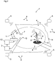
- figure 1 shows a security system 1 for locating a person 2 or an object 8 in a surveillance area, with a movable machine 11, with a control and evaluation unit 3, with at least one radio location system 4, with at least one location-resolving sensor 7 for determining the position of the person 2 or the Object 8, with the radio location system 4 having radio stations 5, with at least one radio transponder 6 being arranged on the person 2 or the object 8, with position data of the person 2 or the object 8 being able to be determined by means of the radio location system 4, with the position data from the radio stations 5 of the radio location system 4 can be transmitted to the control and evaluation unit 3, and position data of the person 2 or the object 8 can be determined by means of the position-resolving sensor 7, the control and evaluation unit 3 is designed to transmit the position data of the
- control and evaluation unit 3 is designed to compare the position data of the radio location system 4 and the position data of the position-resolving sensor 7 and, if they match, to allow the person 2 or the object 8 with the radio transponder 6 in a protective field 13 of the position-resolving sensor 7 and not to emit an object detection signal , whereby the movable machine 11 is in an active state.
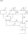
- figure 3 shows a block structure with the various signals.
- a classic safety function with presence detection is supplemented by the location-resolving sensor 7 and safety-related shutdown 16 with a safe position determination.
- the laser scanner 10 monitors according to FIG figure 3 and figure 2 a two-dimensional monitoring area or a measurement data contour 14. This can also be synonymous with a monitoring field.
- the classic safety function is used by the location-resolving sensor 7 as a fallback function that steps in if safe positioning fails.
- the classic safety function is bypassed by means of a muting signal 15 and a machine control 12 can optionally be used for situation-related protection of the movable machine 11 on safe or checked position data 17 of the object 8 or the person 2 fall back.
- the position-resolving sensor 7 which is used in a stationary manner to protect the movable machine 11 or the actuator, also provides its measurement data in order to enable the person 2 or the object 8 to be positioned in the protective field 13 . In this way, if the position data of the radio location system 4 and the position data of the position-resolving sensor 7 are present, the position of the person 2 or the object 8 can be validated and the position information can therefore be used for safety purposes.
- the error case that the position data of the radio location system 4 is missing or the position data of the position-resolving sensor 7 does not match the position data of the radio location system 4 must also be checked for safety-related usability.
- a validation-dependent bridging or muting of the safety function of the primary safety function i.e. the protective field monitoring by the position-resolving sensor 7, is provided, according to which if the position data of the position-resolving sensor 7 and the radio location system 4 match, the person 2 or the object 8 with the radio transponder in a protective field of the allow position-resolving sensor and output no object detection signal, whereby the movable machine 11 or the actuator is in an active state.
- the decisive factor here is that the primary safety function remains bypassed as long as the validation of the position data from the radio location system 4 and the position data from the position-resolving sensor 7 is successful.
- the two independent position data or position information items are validated by the control and evaluation unit 3 .
- the control and evaluation unit 3 is optionally a functionally reliable control and evaluation unit 3.
- the control and evaluation unit 3 has, for example, error detection means. These means are, for example, means for testing, for example a redundant and/or diverse structure with two channels for mutual checking of the results determined and the position data.
- the position-resolving sensor 7 and the radio stations 5 are arranged in a stationary manner.
- This is a stationary application, with the movable machine 11 being a robot, a handling machine or the like, for example.
- the movable machine 11 can also be a processing machine, for example a press or punch, which can also be in direct interaction with a person 2 or an object 8 .
- the position-resolving sensor and the radio stations are arranged in a mobile manner on a movable machine.
- the movable machine being a vehicle, for example, in particular a driverless vehicle or the like.
- the vehicle can also be in direct interaction with a person or an object.
- figure 1 are formed based on the position data of the radio location system 4 and the position data of the position-resolving sensor 7 checked position data, where the control and evaluation unit 3 is designed to compare the checked position data with reference data and if there is a match, the control and evaluation unit changes the safety function of the safety system 1, with the moveable machine 11 or the actuator being operated in a safe operating mode.
- a secure collaboration between the movable machine 11 or actuator and the person 2 can be realized.
- the movable machine 11 or the actuator is decelerated, stopped, deflected and/or accelerated again.
- the movable machine 11 is operated in a safe operating mode.
- Safety-critical errors such as the loss of the radio signal, e.g. B. because there is no radio transponder 6, because a power supply of the radio transponder 6 has failed or because, for example, the radio transponder 6 is shielded or an incorrect localization of the person 2 or the object 8 by the position-resolving sensor 7 or the incorrect processing of position data by the control - And evaluation unit 3 lead to a safety-related shutdown by the primary safety function, namely by the control and evaluation unit 3 if no valid position data from the position-resolving sensor 7 is available.
- the radio location system 4 is optionally an ultra-wideband radio location system, the frequency used being in the range from 3.1 GHz to 10.6 GHz, the transmission power per radio station being a maximum of 0.5 mW.
- At least a single radio transponder 6 must be arranged on the person 2 or the object 8, which is detected by at least three stationarily arranged radio stations 5, the distance between the radio stations 5 being known.
- radio stations 5 are preferably arranged, which monitor at least part of the range of movement of the person 2 or the object 8 .
- At least two or more radio transponders 6 can also be arranged on person 2 or object 8 .
- the position of the person 2 or the object 8 can be identified more precisely and the orientation of the person 2 or the object 8 can also be detected when the person 2 or the object 8 is stationary, if the arrangement of the radio transponder 6 on the person 2 or the object 8 is known.
- the position-resolving sensor 7 is an optoelectronic sensor, an ultrasonic sensor or a radar sensor.
- a time-of-flight sensor as an optoelectronic sensor, the light emitted by a light transmitter, which is remitted by person 2 or object 8, is received by a light receiver and the light propagation time from emission to reception by person 2 or object 8 is evaluated, whereby the distance to the person 2 or the object 8 can be determined.
- the position-resolving sensor 7 can also be an ultrasonic sensor or a radar sensor.
- the spatially resolving sensor 7 is designed for at least extensive monitoring of a monitoring area.
- the position-resolving sensor 7 for at least extensive monitoring of a monitoring area is a sensor for distance measurement.
- the distance sensor supplies distance values in at least two-dimensional space.
- the spatially resolving sensor outputs 7 measured values with distance information and angle information. For example, the distance is determined using the time-of-flight method or triangulation method.
- the position-resolving sensor is designed for at least spatial monitoring of a monitoring area.
- the optoelectronic sensor can be a laser scanner 10 or a safety laser scanner.
- the position-resolving sensor is a 3D camera, a stereo camera or a time-of-flight camera.
Landscapes
- Engineering & Computer Science (AREA)
- Physics & Mathematics (AREA)
- Radar, Positioning & Navigation (AREA)
- Remote Sensing (AREA)
- General Physics & Mathematics (AREA)
- Computer Networks & Wireless Communication (AREA)
- Electromagnetism (AREA)
- General Engineering & Computer Science (AREA)
- Mechanical Engineering (AREA)
- Acoustics & Sound (AREA)
- Automation & Control Theory (AREA)
- Radar Systems Or Details Thereof (AREA)
Priority Applications (3)
| Application Number | Priority Date | Filing Date | Title |
|---|---|---|---|
| EP20154108.3A EP3859382B1 (de) | 2020-01-28 | 2020-01-28 | Sicherheitssystem und verfahren zur lokalisierung einer person oder eines objektes in einem überwachungsbereich mit einem sicherheitssystem |
| US17/159,883 US20210232102A1 (en) | 2020-01-28 | 2021-01-27 | Safety system and method for localizing a person or object in a monitored zone using a safety system |
| CN202110118713.8A CN113253198A (zh) | 2020-01-28 | 2021-01-28 | 安全系统和用安全系统定位监控区域中的人或对象的方法 |
Applications Claiming Priority (1)
| Application Number | Priority Date | Filing Date | Title |
|---|---|---|---|
| EP20154108.3A EP3859382B1 (de) | 2020-01-28 | 2020-01-28 | Sicherheitssystem und verfahren zur lokalisierung einer person oder eines objektes in einem überwachungsbereich mit einem sicherheitssystem |
Publications (2)
| Publication Number | Publication Date |
|---|---|
| EP3859382A1 EP3859382A1 (de) | 2021-08-04 |
| EP3859382B1 true EP3859382B1 (de) | 2022-08-03 |
Family
ID=69374240
Family Applications (1)
| Application Number | Title | Priority Date | Filing Date |
|---|---|---|---|
| EP20154108.3A Active EP3859382B1 (de) | 2020-01-28 | 2020-01-28 | Sicherheitssystem und verfahren zur lokalisierung einer person oder eines objektes in einem überwachungsbereich mit einem sicherheitssystem |
Country Status (3)
| Country | Link |
|---|---|
| US (1) | US20210232102A1 (zh) |
| EP (1) | EP3859382B1 (zh) |
| CN (1) | CN113253198A (zh) |
Families Citing this family (4)
| Publication number | Priority date | Publication date | Assignee | Title |
|---|---|---|---|---|
| DE102020133787A1 (de) | 2020-12-16 | 2022-06-23 | Sick Ag | Sicherheitssystem und Verfahren mit einem Sicherheitssystem |
| DE102022118737B3 (de) * | 2022-07-26 | 2023-09-28 | Pilz Gmbh & Co. Kg | Funkortungssystem mit Testeinrichtung |
| EP4312049A1 (en) | 2022-07-29 | 2024-01-31 | OMRON Corporation | Localizing an rfid tag in a monitored zone |
| DE202022106140U1 (de) * | 2022-11-02 | 2023-08-01 | Leuze Electronic Gmbh + Co. Kg | Überwachungseinrichtung |
Family Cites Families (17)
| Publication number | Priority date | Publication date | Assignee | Title |
|---|---|---|---|---|
| DE4340756C5 (de) | 1992-12-08 | 2006-08-10 | Sick Ag | Laserabstandsermittlungsvorrichtung |
| DE102004043514A1 (de) * | 2004-09-08 | 2006-03-09 | Sick Ag | Verfahren und Vorrichtung zum Steuern einer sicherheitsrelevanten Funktion einer Maschine |
| JP2006311111A (ja) * | 2005-04-27 | 2006-11-09 | Daikin Ind Ltd | 位置検知システムおよび位置検知方法 |
| DE102006048163B4 (de) * | 2006-07-31 | 2013-06-06 | Pilz Gmbh & Co. Kg | Kamerabasierte Überwachung bewegter Maschinen und/oder beweglicher Maschinenelemente zur Kollisionsverhinderung |
| US7768450B2 (en) * | 2007-04-04 | 2010-08-03 | Trimble Navigation Ltd. | Position determination system using radio and laser in combination |
| US20090122340A1 (en) * | 2007-11-13 | 2009-05-14 | Sharp Kabushiki Kaisha | Information processing apparatus, method for controlling print job, and recording medium having information processing program recorded thereon |
| FR2950723B1 (fr) * | 2009-09-28 | 2012-08-17 | Univ Sud Toulon Var | Systeme et procede pour detecter la presence d'un sujet en zone sensible |
| FI122157B (fi) * | 2010-05-10 | 2011-09-15 | Sandvik Mining & Constr Oy | Menetelmä ja laitteisto kaivosajoneuvon turvajärjestelyitä varten |
| DE102012102236A1 (de) * | 2012-03-16 | 2013-09-19 | Pilz Gmbh & Co. Kg | Verfahren und Vorrichtung zum Absichern eines gefährlichen Arbeitsbereichs einer automatisiert arbeitenden Maschine |
| CN103092211B (zh) * | 2013-01-05 | 2015-05-13 | 中国航天空气动力技术研究院 | 一种基于无线电和激光引导的无人机应急着陆方法 |
| DE102016007519A1 (de) * | 2016-06-20 | 2017-12-21 | Kuka Roboter Gmbh | Überwachung einer Anlage mit wenigstens einem Roboter |
| DE102016217532A1 (de) * | 2016-09-14 | 2018-03-15 | Continental Teves Ag & Co. Ohg | Mobile Funkeinheit zur Verbesserung der Verkehrssicherheit |
| DE102017123295A1 (de) | 2017-10-06 | 2019-04-11 | Pilz Gmbh & Co. Kg | Sicherheitssystem zur Absicherung eines kooperativen Betriebs von Menschen, Robotern und Maschinen |
| DE102018117274A1 (de) * | 2018-07-17 | 2020-01-23 | Sick Ag | Sichere Kamera und Verfahren zur sicheren Aufnahme und Auswertung von Bilddaten |
| US10885758B2 (en) * | 2018-11-20 | 2021-01-05 | Transocean Sedeo Forex Ventures Limited | Proximity-based personnel safety system and method |
| US11416000B2 (en) * | 2018-12-07 | 2022-08-16 | Zebra Technologies Corporation | Method and apparatus for navigational ray tracing |
| CN110531398A (zh) * | 2019-09-02 | 2019-12-03 | 中国安全生产科学研究院 | 基于gps与超声波的室外机器人定位系统及方法 |
-
2020
- 2020-01-28 EP EP20154108.3A patent/EP3859382B1/de active Active
-
2021
- 2021-01-27 US US17/159,883 patent/US20210232102A1/en not_active Abandoned
- 2021-01-28 CN CN202110118713.8A patent/CN113253198A/zh active Pending
Also Published As
| Publication number | Publication date |
|---|---|
| EP3859382A1 (de) | 2021-08-04 |
| US20210232102A1 (en) | 2021-07-29 |
| CN113253198A (zh) | 2021-08-13 |
Similar Documents
| Publication | Publication Date | Title |
|---|---|---|
| EP3859382B1 (de) | Sicherheitssystem und verfahren zur lokalisierung einer person oder eines objektes in einem überwachungsbereich mit einem sicherheitssystem | |
| EP3855208B1 (de) | Sicherheitssystem und verfahren | |
| EP3828584B1 (de) | Sicherheitssystem | |
| EP2722684B1 (de) | Laserscanner | |
| EP2386876A1 (de) | Entfernungsmessender optoelektronischer Sicherheitssensor und Verfahren zur Überwachung eines Überwachungsbereichs | |
| EP3078985B1 (de) | Optoelektronischer sensor und verfahren zur transmissionsüberwachung einer frontscheibe | |
| EP2937715B1 (de) | Optoelektronischer Sensor und Verfahren zur Erfassung von Messinformationen aus einem Überwachungsbereich | |
| EP3220164B1 (de) | Verfahren zum betreiben eines abstandsmessenden überwachungssensors und überwachungssensor | |
| EP3330741B1 (de) | Optoelektronischer sensor und verfahren zur erfassung von objekten in einem erfassungsbereich | |
| EP3740784A1 (de) | Verfahren und vorrichtung zum detektieren kritischer querbewegungen | |
| EP4030188A1 (de) | Vorrichtung und verfahren zum absichern eines überwachungsbereiches | |
| EP3910231B1 (de) | Sicherheitssystem | |
| DE202019106569U1 (de) | Sicherheitssystem | |
| DE202020100454U1 (de) | Sicherheitssystem zur Lokalisierung einer Person oder eines Objektes in einem Überwachungsbereich | |
| EP2682780B1 (de) | Verfahren zur sicheren Erfassung und Positionsbestimmung von Objekten und Sicherheitsvorrichtung | |
| EP3812863B1 (de) | Bewegbare maschine | |
| EP3527332A1 (de) | Sichere sensorvorrichtung und verfahren zur absicherung einer beweglichen maschine | |
| EP3578867B1 (de) | Sensorsystem mit optoelektronischen distanzsensoren | |
| DE102021120131A1 (de) | Sicherheitssystem und Verfahren mit einem Sicherheitssystem | |
| EP2515143A1 (de) | Verfahren zur sicheren Erfassung und Positionsbestimmung von Objekten und Sicherheitsvorrichtung | |
| DE102021120130A1 (de) | Sicherheitssystem und Verfahren mit einem Sicherheitssystem | |
| US20240159355A1 (en) | Safety system and method using a safety system | |
| DE202022106398U1 (de) | Sicherheitssystem mit einem Sicherheitssystem | |
| EP1249711B1 (de) | Vorrichtung zum Erkennen einer Kollisionsgefahr zwischen zwei sich relativ zueinander bewegenden Objekten, insbesondere Fahrzeugen | |
| DE202022106978U1 (de) | System mit einem Sensor |
Legal Events
| Date | Code | Title | Description |
|---|---|---|---|
| PUAI | Public reference made under article 153(3) epc to a published international application that has entered the european phase |
Free format text: ORIGINAL CODE: 0009012 |
|
| STAA | Information on the status of an ep patent application or granted ep patent |
Free format text: STATUS: THE APPLICATION HAS BEEN PUBLISHED |
|
| AK | Designated contracting states |
Kind code of ref document: A1 Designated state(s): AL AT BE BG CH CY CZ DE DK EE ES FI FR GB GR HR HU IE IS IT LI LT LU LV MC MK MT NL NO PL PT RO RS SE SI SK SM TR |
|
| STAA | Information on the status of an ep patent application or granted ep patent |
Free format text: STATUS: REQUEST FOR EXAMINATION WAS MADE |
|
| 17P | Request for examination filed |
Effective date: 20211221 |
|
| RBV | Designated contracting states (corrected) |
Designated state(s): AL AT BE BG CH CY CZ DE DK EE ES FI FR GB GR HR HU IE IS IT LI LT LU LV MC MK MT NL NO PL PT RO RS SE SI SK SM TR |
|
| RIC1 | Information provided on ipc code assigned before grant |
Ipc: F16P 3/12 20060101ALI20220303BHEP Ipc: G01S 13/00 20060101AFI20220303BHEP |
|
| GRAP | Despatch of communication of intention to grant a patent |
Free format text: ORIGINAL CODE: EPIDOSNIGR1 |
|
| STAA | Information on the status of an ep patent application or granted ep patent |
Free format text: STATUS: GRANT OF PATENT IS INTENDED |
|
| INTG | Intention to grant announced |
Effective date: 20220506 |
|
| GRAS | Grant fee paid |
Free format text: ORIGINAL CODE: EPIDOSNIGR3 |
|
| GRAA | (expected) grant |
Free format text: ORIGINAL CODE: 0009210 |
|
| STAA | Information on the status of an ep patent application or granted ep patent |
Free format text: STATUS: THE PATENT HAS BEEN GRANTED |
|
| AK | Designated contracting states |
Kind code of ref document: B1 Designated state(s): AL AT BE BG CH CY CZ DE DK EE ES FI FR GB GR HR HU IE IS IT LI LT LU LV MC MK MT NL NO PL PT RO RS SE SI SK SM TR |
|
| REG | Reference to a national code |
Ref country code: AT Ref legal event code: REF Ref document number: 1509182 Country of ref document: AT Kind code of ref document: T Effective date: 20220815 Ref country code: CH Ref legal event code: EP |
|
| REG | Reference to a national code |
Ref country code: DE Ref legal event code: R096 Ref document number: 502020001437 Country of ref document: DE |
|
| REG | Reference to a national code |
Ref country code: IE Ref legal event code: FG4D Free format text: LANGUAGE OF EP DOCUMENT: GERMAN |
|
| REG | Reference to a national code |
Ref country code: LT Ref legal event code: MG9D |
|
| REG | Reference to a national code |
Ref country code: NL Ref legal event code: MP Effective date: 20220803 |
|
| PG25 | Lapsed in a contracting state [announced via postgrant information from national office to epo] |
Ref country code: SE Free format text: LAPSE BECAUSE OF FAILURE TO SUBMIT A TRANSLATION OF THE DESCRIPTION OR TO PAY THE FEE WITHIN THE PRESCRIBED TIME-LIMIT Effective date: 20220803 Ref country code: RS Free format text: LAPSE BECAUSE OF FAILURE TO SUBMIT A TRANSLATION OF THE DESCRIPTION OR TO PAY THE FEE WITHIN THE PRESCRIBED TIME-LIMIT Effective date: 20220803 Ref country code: PT Free format text: LAPSE BECAUSE OF FAILURE TO SUBMIT A TRANSLATION OF THE DESCRIPTION OR TO PAY THE FEE WITHIN THE PRESCRIBED TIME-LIMIT Effective date: 20221205 Ref country code: NO Free format text: LAPSE BECAUSE OF FAILURE TO SUBMIT A TRANSLATION OF THE DESCRIPTION OR TO PAY THE FEE WITHIN THE PRESCRIBED TIME-LIMIT Effective date: 20221103 Ref country code: NL Free format text: LAPSE BECAUSE OF FAILURE TO SUBMIT A TRANSLATION OF THE DESCRIPTION OR TO PAY THE FEE WITHIN THE PRESCRIBED TIME-LIMIT Effective date: 20220803 Ref country code: LV Free format text: LAPSE BECAUSE OF FAILURE TO SUBMIT A TRANSLATION OF THE DESCRIPTION OR TO PAY THE FEE WITHIN THE PRESCRIBED TIME-LIMIT Effective date: 20220803 Ref country code: LT Free format text: LAPSE BECAUSE OF FAILURE TO SUBMIT A TRANSLATION OF THE DESCRIPTION OR TO PAY THE FEE WITHIN THE PRESCRIBED TIME-LIMIT Effective date: 20220803 Ref country code: FI Free format text: LAPSE BECAUSE OF FAILURE TO SUBMIT A TRANSLATION OF THE DESCRIPTION OR TO PAY THE FEE WITHIN THE PRESCRIBED TIME-LIMIT Effective date: 20220803 Ref country code: ES Free format text: LAPSE BECAUSE OF FAILURE TO SUBMIT A TRANSLATION OF THE DESCRIPTION OR TO PAY THE FEE WITHIN THE PRESCRIBED TIME-LIMIT Effective date: 20220803 |
|
| PG25 | Lapsed in a contracting state [announced via postgrant information from national office to epo] |
Ref country code: PL Free format text: LAPSE BECAUSE OF FAILURE TO SUBMIT A TRANSLATION OF THE DESCRIPTION OR TO PAY THE FEE WITHIN THE PRESCRIBED TIME-LIMIT Effective date: 20220803 Ref country code: IS Free format text: LAPSE BECAUSE OF FAILURE TO SUBMIT A TRANSLATION OF THE DESCRIPTION OR TO PAY THE FEE WITHIN THE PRESCRIBED TIME-LIMIT Effective date: 20221203 Ref country code: HR Free format text: LAPSE BECAUSE OF FAILURE TO SUBMIT A TRANSLATION OF THE DESCRIPTION OR TO PAY THE FEE WITHIN THE PRESCRIBED TIME-LIMIT Effective date: 20220803 Ref country code: GR Free format text: LAPSE BECAUSE OF FAILURE TO SUBMIT A TRANSLATION OF THE DESCRIPTION OR TO PAY THE FEE WITHIN THE PRESCRIBED TIME-LIMIT Effective date: 20221104 |
|
| PG25 | Lapsed in a contracting state [announced via postgrant information from national office to epo] |
Ref country code: SM Free format text: LAPSE BECAUSE OF FAILURE TO SUBMIT A TRANSLATION OF THE DESCRIPTION OR TO PAY THE FEE WITHIN THE PRESCRIBED TIME-LIMIT Effective date: 20220803 Ref country code: RO Free format text: LAPSE BECAUSE OF FAILURE TO SUBMIT A TRANSLATION OF THE DESCRIPTION OR TO PAY THE FEE WITHIN THE PRESCRIBED TIME-LIMIT Effective date: 20220803 Ref country code: DK Free format text: LAPSE BECAUSE OF FAILURE TO SUBMIT A TRANSLATION OF THE DESCRIPTION OR TO PAY THE FEE WITHIN THE PRESCRIBED TIME-LIMIT Effective date: 20220803 Ref country code: CZ Free format text: LAPSE BECAUSE OF FAILURE TO SUBMIT A TRANSLATION OF THE DESCRIPTION OR TO PAY THE FEE WITHIN THE PRESCRIBED TIME-LIMIT Effective date: 20220803 |
|
| PGFP | Annual fee paid to national office [announced via postgrant information from national office to epo] |
Ref country code: FR Payment date: 20230123 Year of fee payment: 4 |
|
| REG | Reference to a national code |
Ref country code: DE Ref legal event code: R097 Ref document number: 502020001437 Country of ref document: DE |
|
| PG25 | Lapsed in a contracting state [announced via postgrant information from national office to epo] |
Ref country code: SK Free format text: LAPSE BECAUSE OF FAILURE TO SUBMIT A TRANSLATION OF THE DESCRIPTION OR TO PAY THE FEE WITHIN THE PRESCRIBED TIME-LIMIT Effective date: 20220803 Ref country code: EE Free format text: LAPSE BECAUSE OF FAILURE TO SUBMIT A TRANSLATION OF THE DESCRIPTION OR TO PAY THE FEE WITHIN THE PRESCRIBED TIME-LIMIT Effective date: 20220803 |
|
| PLBE | No opposition filed within time limit |
Free format text: ORIGINAL CODE: 0009261 |
|
| STAA | Information on the status of an ep patent application or granted ep patent |
Free format text: STATUS: NO OPPOSITION FILED WITHIN TIME LIMIT |
|
| PG25 | Lapsed in a contracting state [announced via postgrant information from national office to epo] |
Ref country code: AL Free format text: LAPSE BECAUSE OF FAILURE TO SUBMIT A TRANSLATION OF THE DESCRIPTION OR TO PAY THE FEE WITHIN THE PRESCRIBED TIME-LIMIT Effective date: 20220803 |
|
| 26N | No opposition filed |
Effective date: 20230504 |
|
| PG25 | Lapsed in a contracting state [announced via postgrant information from national office to epo] |
Ref country code: SI Free format text: LAPSE BECAUSE OF FAILURE TO SUBMIT A TRANSLATION OF THE DESCRIPTION OR TO PAY THE FEE WITHIN THE PRESCRIBED TIME-LIMIT Effective date: 20220803 |
|
| PG25 | Lapsed in a contracting state [announced via postgrant information from national office to epo] |
Ref country code: LU Free format text: LAPSE BECAUSE OF NON-PAYMENT OF DUE FEES Effective date: 20230128 |
|
| REG | Reference to a national code |
Ref country code: BE Ref legal event code: MM Effective date: 20230131 |
|
| PG25 | Lapsed in a contracting state [announced via postgrant information from national office to epo] |
Ref country code: BE Free format text: LAPSE BECAUSE OF NON-PAYMENT OF DUE FEES Effective date: 20230131 |
|
| PG25 | Lapsed in a contracting state [announced via postgrant information from national office to epo] |
Ref country code: IE Free format text: LAPSE BECAUSE OF NON-PAYMENT OF DUE FEES Effective date: 20230128 |
|
| PGFP | Annual fee paid to national office [announced via postgrant information from national office to epo] |
Ref country code: DE Payment date: 20240119 Year of fee payment: 5 Ref country code: GB Payment date: 20240124 Year of fee payment: 5 Ref country code: CH Payment date: 20240202 Year of fee payment: 5 |