EP3859365A1 - Current protection system for energy storage system - Google Patents
Current protection system for energy storage system Download PDFInfo
- Publication number
- EP3859365A1 EP3859365A1 EP21154450.7A EP21154450A EP3859365A1 EP 3859365 A1 EP3859365 A1 EP 3859365A1 EP 21154450 A EP21154450 A EP 21154450A EP 3859365 A1 EP3859365 A1 EP 3859365A1
- Authority
- EP
- European Patent Office
- Prior art keywords
- battery
- current
- current measurement
- control unit
- short circuit
- Prior art date
- Legal status (The legal status is an assumption and is not a legal conclusion. Google has not performed a legal analysis and makes no representation as to the accuracy of the status listed.)
- Granted
Links
Images


Classifications
-
- H—ELECTRICITY
- H02—GENERATION; CONVERSION OR DISTRIBUTION OF ELECTRIC POWER
- H02J—ELECTRIC POWER NETWORKS; CIRCUIT ARRANGEMENTS OR SYSTEMS FOR SUPPLYING OR DISTRIBUTING ELECTRIC POWER; SYSTEMS FOR STORING ELECTRIC ENERGY
- H02J7/00—Circuit arrangements for charging or discharging batteries or for supplying loads from batteries
- H02J7/60—Circuit arrangements for charging or discharging batteries or for supplying loads from batteries including safety or protection arrangements
- H02J7/663—Circuit arrangements for charging or discharging batteries or for supplying loads from batteries including safety or protection arrangements using battery or load disconnect circuits
-
- G—PHYSICS
- G01—MEASURING; TESTING
- G01R—MEASURING ELECTRIC VARIABLES; MEASURING MAGNETIC VARIABLES
- G01R31/00—Arrangements for testing electric properties; Arrangements for locating electric faults; Arrangements for electrical testing characterised by what is being tested not provided for elsewhere
- G01R31/36—Arrangements for testing, measuring or monitoring the electrical condition of accumulators or electric batteries, e.g. capacity or state of charge [SoC]
- G01R31/396—Acquisition or processing of data for testing or for monitoring individual cells or groups of cells within a battery
-
- G—PHYSICS
- G01—MEASURING; TESTING
- G01R—MEASURING ELECTRIC VARIABLES; MEASURING MAGNETIC VARIABLES
- G01R1/00—Details of instruments or arrangements of the types included in groups G01R5/00 - G01R13/00 and G01R31/00
- G01R1/20—Modifications of basic electric elements for use in electric measuring instruments; Structural combinations of such elements with such instruments
- G01R1/203—Resistors used for electric measuring, e.g. decade resistors standards, resistors for comparators, series resistors, shunts
-
- G—PHYSICS
- G01—MEASURING; TESTING
- G01R—MEASURING ELECTRIC VARIABLES; MEASURING MAGNETIC VARIABLES
- G01R19/00—Arrangements for measuring currents or voltages or for indicating presence or sign thereof
- G01R19/10—Measuring sum, difference or ratio
-
- G—PHYSICS
- G01—MEASURING; TESTING
- G01R—MEASURING ELECTRIC VARIABLES; MEASURING MAGNETIC VARIABLES
- G01R31/00—Arrangements for testing electric properties; Arrangements for locating electric faults; Arrangements for electrical testing characterised by what is being tested not provided for elsewhere
- G01R31/36—Arrangements for testing, measuring or monitoring the electrical condition of accumulators or electric batteries, e.g. capacity or state of charge [SoC]
- G01R31/382—Arrangements for monitoring battery or accumulator variables, e.g. SoC
-
- G—PHYSICS
- G01—MEASURING; TESTING
- G01R—MEASURING ELECTRIC VARIABLES; MEASURING MAGNETIC VARIABLES
- G01R31/00—Arrangements for testing electric properties; Arrangements for locating electric faults; Arrangements for electrical testing characterised by what is being tested not provided for elsewhere
- G01R31/36—Arrangements for testing, measuring or monitoring the electrical condition of accumulators or electric batteries, e.g. capacity or state of charge [SoC]
- G01R31/382—Arrangements for monitoring battery or accumulator variables, e.g. SoC
- G01R31/3828—Arrangements for monitoring battery or accumulator variables, e.g. SoC using current integration
- G01R31/3832—Arrangements for monitoring battery or accumulator variables, e.g. SoC using current integration without measurement of battery voltage
-
- G—PHYSICS
- G01—MEASURING; TESTING
- G01R—MEASURING ELECTRIC VARIABLES; MEASURING MAGNETIC VARIABLES
- G01R31/00—Arrangements for testing electric properties; Arrangements for locating electric faults; Arrangements for electrical testing characterised by what is being tested not provided for elsewhere
- G01R31/50—Testing of electric apparatus, lines, cables or components for short-circuits, continuity, leakage current or incorrect line connections
- G01R31/52—Testing for short-circuits, leakage current or ground faults
-
- H—ELECTRICITY
- H01—ELECTRIC ELEMENTS
- H01M—PROCESSES OR MEANS, e.g. BATTERIES, FOR THE DIRECT CONVERSION OF CHEMICAL ENERGY INTO ELECTRICAL ENERGY
- H01M10/00—Secondary cells; Manufacture thereof
- H01M10/42—Methods or arrangements for servicing or maintenance of secondary cells or secondary half-cells
- H01M10/425—Structural combination with electronic components, e.g. electronic circuits integrated to the outside of the casing
-
- H—ELECTRICITY
- H02—GENERATION; CONVERSION OR DISTRIBUTION OF ELECTRIC POWER
- H02J—ELECTRIC POWER NETWORKS; CIRCUIT ARRANGEMENTS OR SYSTEMS FOR SUPPLYING OR DISTRIBUTING ELECTRIC POWER; SYSTEMS FOR STORING ELECTRIC ENERGY
- H02J7/00—Circuit arrangements for charging or discharging batteries or for supplying loads from batteries
- H02J7/60—Circuit arrangements for charging or discharging batteries or for supplying loads from batteries including safety or protection arrangements
-
- H—ELECTRICITY
- H02—GENERATION; CONVERSION OR DISTRIBUTION OF ELECTRIC POWER
- H02J—ELECTRIC POWER NETWORKS; CIRCUIT ARRANGEMENTS OR SYSTEMS FOR SUPPLYING OR DISTRIBUTING ELECTRIC POWER; SYSTEMS FOR STORING ELECTRIC ENERGY
- H02J7/00—Circuit arrangements for charging or discharging batteries or for supplying loads from batteries
- H02J7/60—Circuit arrangements for charging or discharging batteries or for supplying loads from batteries including safety or protection arrangements
- H02J7/62—Circuit arrangements for charging or discharging batteries or for supplying loads from batteries including safety or protection arrangements against overcurrent
-
- H—ELECTRICITY
- H02—GENERATION; CONVERSION OR DISTRIBUTION OF ELECTRIC POWER
- H02J—ELECTRIC POWER NETWORKS; CIRCUIT ARRANGEMENTS OR SYSTEMS FOR SUPPLYING OR DISTRIBUTING ELECTRIC POWER; SYSTEMS FOR STORING ELECTRIC ENERGY
- H02J7/00—Circuit arrangements for charging or discharging batteries or for supplying loads from batteries
- H02J7/60—Circuit arrangements for charging or discharging batteries or for supplying loads from batteries including safety or protection arrangements
- H02J7/63—Circuit arrangements for charging or discharging batteries or for supplying loads from batteries including safety or protection arrangements against overdischarge
-
- H—ELECTRICITY
- H01—ELECTRIC ELEMENTS
- H01M—PROCESSES OR MEANS, e.g. BATTERIES, FOR THE DIRECT CONVERSION OF CHEMICAL ENERGY INTO ELECTRICAL ENERGY
- H01M10/00—Secondary cells; Manufacture thereof
- H01M10/42—Methods or arrangements for servicing or maintenance of secondary cells or secondary half-cells
- H01M10/425—Structural combination with electronic components, e.g. electronic circuits integrated to the outside of the casing
- H01M2010/4271—Battery management systems including electronic circuits, e.g. control of current or voltage to keep battery in healthy state, cell balancing
-
- H—ELECTRICITY
- H02—GENERATION; CONVERSION OR DISTRIBUTION OF ELECTRIC POWER
- H02J—ELECTRIC POWER NETWORKS; CIRCUIT ARRANGEMENTS OR SYSTEMS FOR SUPPLYING OR DISTRIBUTING ELECTRIC POWER; SYSTEMS FOR STORING ELECTRIC ENERGY
- H02J7/00—Circuit arrangements for charging or discharging batteries or for supplying loads from batteries
- H02J7/80—Circuit arrangements for charging or discharging batteries or for supplying loads from batteries including monitoring or indicating arrangements
-
- Y—GENERAL TAGGING OF NEW TECHNOLOGICAL DEVELOPMENTS; GENERAL TAGGING OF CROSS-SECTIONAL TECHNOLOGIES SPANNING OVER SEVERAL SECTIONS OF THE IPC; TECHNICAL SUBJECTS COVERED BY FORMER USPC CROSS-REFERENCE ART COLLECTIONS [XRACs] AND DIGESTS
- Y02—TECHNOLOGIES OR APPLICATIONS FOR MITIGATION OR ADAPTATION AGAINST CLIMATE CHANGE
- Y02E—REDUCTION OF GREENHOUSE GAS [GHG] EMISSIONS, RELATED TO ENERGY GENERATION, TRANSMISSION OR DISTRIBUTION
- Y02E60/00—Enabling technologies; Technologies with a potential or indirect contribution to GHG emissions mitigation
- Y02E60/10—Energy storage using batteries
Definitions
- Embodiments relate to a current protection system for an energy storage system.
- An energy storage system quickly charges and discharges large capacity power, and may be provided with one or more functions so that the system can be safely stopped when an accident such as an electric shock, a short circuit, or fire occurs.
- Embodiments are directed to a current protection system for an energy storage system, including: batteries connected in parallel; battery control units respectively connected to the batteries, and respectively having battery current measurement units; a battery connection panel connecting the battery control units to one connection point, the battery connection panel having a contact point current measurement unit; and a control unit configured to sum current values respectively measured by the battery current measurement units and a current value measured by the contact point current measurement unit, and to detect a presence of an internal short circuit based on the sum.
- control unit may determine that the internal short circuit is present.
- control unit may determine that the internal short circuit is not present.
- control unit may generate a trip signal to stop the energy storage system.
- a direction of current measured by the contact point current measurement unit may be set to be opposite to a direction of current measured by the battery current measurement units.
- the control unit may detect a high resistance short circuit accident according to insulation breakdown of a battery cable.
- a direction of current measured by the contact point current measurement unit may be switched to an opposite direction.
- the current protection system may further include a power conditioning system connected to the battery connection panel, the power conditioning system being configured to convert electrical characteristics so as to receive electrical energy from an electricity generation device to charge the battery, or to emit energy stored in the battery to an electric power system.
- a power conditioning system connected to the battery connection panel, the power conditioning system being configured to convert electrical characteristics so as to receive electrical energy from an electricity generation device to charge the battery, or to emit energy stored in the battery to an electric power system.
- the battery current measurement units and the contact point current measurement unit may be formed of shunt resistors.
- FIG. 1 is a block diagram illustrating a current protection system for an energy storage system according to an example embodiment.
- FIG. 2 is a circuit diagram illustrating a current protection system for an energy storage system according to an example embodiment.
- a current protection system 100 may include a plurality of batteries 110, a plurality of battery control units (BCUs) 120, a battery connection panel (BCP) 130, a control unit 140, and a power conditioning system (PCS) 150.
- BCUs battery control units
- BCP battery connection panel
- PCS power conditioning system
- the plurality of batteries 110 may be connected in parallel. Each of the batteries 110 may be formed of a plurality of battery cells connected in series and/or parallel.
- the plurality of batteries 110 may include a first battery to an n-th battery 110_1 to 110_n. For the sake of explanation, the battery 110 will be described using an example in which 50 batteries 110_1 to 110_50 connected in parallel.
- the battery control units 120 may be respectively connected which monitor the states of the batteries 110, and control charging and discharging of the batteries 110.
- the number of the battery control units 120 may be the same as that of the batteries 110, and the plurality of battery control units 120 may include a first battery control unit to an n-th battery control unit 120_1 to 120_n.
- the plurality of battery control units 120 may each have the same structure. Thus, for the sake of explanation, only a first battery control unit 120_1 will be described in detail. In addition, for convenience, the first battery control unit 120_1 may be referred to as a battery control unit 120.
- the battery control unit 120 may include a fuse 121, and a battery current measurement unit 122, and a DC contactor 123.
- the battery control unit 120 may include at least one fuse 121 to be cut to protect the battery 110, when the current flowing through the battery 110 is equal to or greater than a set current due to an overcurrent or a short circuit, etc.
- the battery current measurement unit 122 may measure a value and determine a direction of current flowing through the battery 110, and provide the measured current value and determined current direction to the control unit 140.
- the battery current measurement unit 122 may include or be formed of a shunt resistor.
- the battery current measurement unit 122 may detect a direction from a minus terminal C- of the battery connection panel 130 to a minus terminal B- of the battery 110 as a forward direction or a first direction, and may detect a direction from the minus terminal B- of the battery 110 to the minus terminal C- of the battery connection panel 130 as a reverse direction or a second direction.
- the battery 110 and the battery control unit 120 may be referred to together as a battery pack.
- a plurality of the battery packs may be connected in parallel to the battery connection panel 130.
- the battery connection panel 130 may be electrically connected to each of the plurality of battery control units 120.
- the battery connection panel 130 may bind the plurality of battery packs to one connection point. For example, plus terminals P+ of the plurality of battery control units 120 may all be electrically connected to a plus terminal C+ of the battery connection panel 130, and minus terminals P- of the plurality of battery control units 120 may all be electrically connected to the minus terminal C- of the battery connection panel 130.
- the battery connection panel 130 may include a contact point current measurement unit 131.
- the contact point current measurement unit 131 may measure a value of the current and determine a direction of the current flowing through the battery connection panel 130, and provide the measured value and current direction to the control unit 140.
- the contact point current measurement unit 131 may include or be formed of a shunt resistor.
- the terms contact point and connection point may be used interchangeably.
- the contact point current measurement unit 131 may detect a direction from the minus terminal C- of the battery connection panel 130 to a minus terminal of the power conditioning system 150 as a forward direction or a first direction, and detect a direction from the minus terminal of the power conditioning system 150 to the minus terminal C- of the battery connection panel 130 as a reverse direction or a second direction.
- the current direction measured by the contact point current measurement unit 131 in the battery connection panel 130 may be set to be opposite to that measured by the battery current measurement unit 122 in the battery control unit 120.
- the current direction measured by the contact point current measurement unit 131 in the battery connection panel 130 may be measured opposite to the direction of the current actually flowing through the battery connection panel 130, and thus may have an opposite sign.
- the control unit 140 may be connected to the plurality of the battery control units 120 and the battery connection panel 130 to determine an internal short circuit (or an abnormal state) between the battery control units 120 and the battery connection panel 130.
- the control unit 140 may receive the current value measured by the battery current measurement unit 122 in each of the battery control units 120, and the current value measured by the contact point current measurement unit 131 in the battery connection panel 130, and may determine whether the internal short circuit occurs or is present.
- I 1 to I n , and I p are illustrated in FIG. 2 . It is assumed that the incoming direction of the current on the basis of the node is '+', and the outgoing direction of the current is '-'.
- the node in FIG. 2 indicates a point at which the plurality of battery packs and the battery connection panel 130 meet.
- the control unit 140 may sum the current value measured by each of the battery current measurement unit 122 and the current value measured by the contact point current measurement unit 131 to determine whether there occurs the internal short circuit.
- the current measured at the contact point current measurement unit 131 is -I p , because the current direction measured at the contact point current measurement unit 131 is set opposite to that measured by the battery current measurement unit 122. This may be interpreted to have the same meaning as that the current outgoing from the node is considered as (-) in Kirchhoff's law.
- the control unit 140 may determine that the current protection system 100 is in a normal state because current vectors of both sides are parallel on the basis of the node. In addition, when the sum of the current values respectively measured by the battery current measurement units 122 and the current value measured at the contact point current measurement unit 131 is not 0, the control unit 140 may determine that the current vectors are on one side, thus indicating an internal short circuit. Accordingly, the control unit 140 may generate a trip signal to stop the current protection system 100 for the energy storage system.
- the power conditioning system (PCS) 150 may be connected to the battery connection panel 130, and may receive electrical energy from an electric power system or a power generation device (such as a renewable energy source) to perform conversion the electrical characteristics (AC/DC, voltage, frequency, or the like) in order to charge the battery 110. or in order to provide the energy stored in the battery 110 to the outside.
- an electric power system or a power generation device such as a renewable energy source
- control unit 140 may determine whether the internal short circuit occurs, may distinguish a disturbance such as a temporary temperature change or surge from a short circuit accident, and may reduce a "gray zone" between the short circuit and overcurrent, wherein the "gray zone" corresponds to a range of values of parameters such as current or temperature, for which it is unclear whether a short circuit has occurred.
- This method allows protections coordination between functions. Accordingly, the present example embodiment may reduce a non-operation time of the energy storage system and enhance efficiency.
- FIG. 3 is a graph showing fuse melting and power cable breakdown according to a current in an I 1 direction and time as logarithmic functions.
- FIG. 4 is a graph showing fuse melting and power cable breakdown according to a current in an I total direction and time as logarithmic functions.
- a fuse or a current meter may be used to protect a system from an overcurrent or a short-circuit current in an energy storage system.
- the short circuit accident due to the overcurrent and the short-circuit current may be distinguished according to the magnitude of a resistance at a fault point, e.g., as the magnitude of the resistance becomes smaller, the fault current becomes large, and the case in which a current greater than ten times the typical continuous current rating flows may be defined as a short circuit.
- a protection coordinate for the short-circuit current and the overcurrent may not be desirable, and thus a gray zone may exist. The gray zone will be described in detail with reference to FIGS. 3 and 4 .
- FIG. 3 illustrates a current-time (I-T) curve from the perspective of I 1 .
- a curve 'BCU Fuse' shows an operation of a fuse according to the magnitude of the current I 1 generated in the battery control unit 120.
- the left side is the gray zone
- the right side is a protection zone. Specifically, when the trajectory of the short-circuit current flowing through the battery control unit 120 enters the protection zone of the BCU Fuse curve, the fuse is melted to block the short-circuit current. On the other hand, when the trajectory of the short-circuit current remains in the gray zone, the battery control unit 120 is not isolated by the fuse.
- a curve '4 AWG' shows a short-circuit strength curve of a battery power cable, wherein the left side is a safety zone, and the right side is an insulation breakdown zone.
- the protection coordination is performed among the BCU Fuse, the power cable, and the BCU overcurrent protection device.
- the short-circuit current enters the protection zone of the BCU Fuse along the trajectory of the short-circuit current to be blocked by the fuse.
- FIG. 4 illustrates the I-T curve from the perspective of I total , where I total is the sum of Ia and I p , I a is the sum of the currents of 49 BCUs, and I p means the current of the BCP.
- the curve '4 AWG' is for a power cable at a short circuit accident point, and is the same as that in FIG. 3 .
- FIG. 4 is viewed in perspective of I total , where the BCU OCP curve is the sum of curves of 49 overcurrent protection devices, and the BCU Fuse is the sum of 49 fuses.
- the BCU Fuse curve in FIG. 4 is positioned further to the right side than the 4 AWG curve.
- the 4 AWG curve is positioned further to the left side than the BCU Fuse curve, when a short-circuit accident occurs, cable insulation breakdown may occur which is not protected according to the I total current.
- example embodiments may enhance safety by including the control unit 140 in order to prevent a high resistance short-circuit accident corresponding to the non-protection area between an overcurrent and the short-circuit accident.
- the control unit 140 may compare the current values respectively measured by the battery current measurement units 122 in the battery control units 120, and the current value measured by the contact point current measurement unit 131 in the battery connection panel 130, and may determine whether the short circuit occurs. Specifically, when the sum of the current values respectively measured by the battery current measurement units 122 and the current value measured by the contact point current measurement unit 131 is 0, the control unit 140 may determine that the current protection system 100 is in a normal state or that an internal short circuit is not present.
- the control unit 140 may determine that the short circuit accident occurs. This is because the current direction of the contact point measurement unit 131 is set opposite to that of the battery current measurement unit 122. Thus, when the sum of the current values respectively measured by the battery current measurement units 122 and the current value measured at the contact point current measurement unit 131 is 0 and the current vectors of both sides are made parallel the control unit 140 may determine the normal state. On the other hand, when a short circuit occurs between the battery connection panel 130 and any one among the plurality of battery control units 120, the direction of the current flowing through the battery connection panel 130 may be changed. Accordingly, when the sum of the current values respectively measured by the battery current measurement units 122 and the current value measured at the contact point current measurement unit 131 becomes greater than 0 and the current vectors are on one side, the control unit 140 may determine that the short circuit accident occurs.
- FIG. 5 is a circuit diagram illustrating a state in which an internal accident occurs in a current protection system for an energy storage system according to an example embodiment
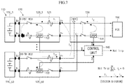
- FIGS. 6 and 7 are circuit diagrams illustrating a state in which an external accident occurs.
- control unit 140 determines whether a short circuit occurs when a short circuit accident occurs between the first battery control unit 120_1 and the battery connection panel 130.
- the current I 1 flowing through the first battery control unit 120_1 flows to the short circuit point.
- the current in the first battery control unit 120_1 flows in the same forward direction (first direction) as before the short circuit.
- the currents in the second to 50th battery control units 120_2 to 120_50, in which the short circuits do not occur, flow in the same forward direction (first direction) as before the short circuit.
- the current I p flowing through the battery connection panel 130 flows to the short circuit point in the forward direction (first direction) that is opposite to before the short circuit.
- the control unit 140 receives the currents measured by the respective battery current measurement units 122 and the current measured by the contact point current measurement unit 131.
- the control unit 140 may generate a trip signal to stop the system.
- the control unit 140 may compare the current values respectively measured by the battery current measurement units 122 to determine that the short circuit occurs in the first battery control unit 120_1, which has the largest current value.
- I z is the sum of the currents of the second to 50th battery control units 120_2 to 120_50 in which the short circuit does not occur.
- the equation applied with the same will be represented as the following Equation. I 1 + I z + I p ⁇ 0
- the control unit 140 does not generate a trip signal when the system is in a normal state, or when an external accident occurs.
- the external accident means an accident occurring between the battery 110 and the battery control units 120 and between the battery connection panel 130 and the power conditioning system 150, rather than between the battery connection panel 130 and the battery control units 120.
- control unit 140 determines whether a short circuit occurs when a short circuit accident occurs between the battery connection panel 130 and the power conditioning system 150.
- the currents I 1 to I 50 flowing through the first battery control unit to the 50th battery control unit 120_1 to 120_50 flow to the short circuit point.
- the currents of the respective battery control units 120 flow in the same forward direction (first direction) as before the short circuit.
- the current I p flowing through the battery connection panel 130 also flows to the short circuit point in the reverse direction (second direction) that is same as before the short circuit.
- the control unit 140 receives the currents measured by the respective battery current measurement units 122 and the current measured by the contact point current measurement unit 131.
- control unit 140 does not start system blocking. Instead, for the aforementioned external accident, the current is blocked by the fuse of the power conditioning system 150 to stop the system.
- control unit 140 determines whether a short circuit occurs when a short circuit accident occurs between the first battery 110_1 and the battery control unit 120_1.
- the current I 1 flowing through the first battery control unit 120_1 flows to the short circuit point.
- the current of the first battery control unit 120_1 flows in the reverse direction (second direction), which is opposite to before the short circuit.
- the currents of the second to 50th battery control units 120_2 to 120_50, in which the short circuit does not occur, flow in the same forward direction (first direction) as before the short circuit.
- the current I p flowing through the battery connection panel 130 flows to the short circuit point in the forward direction (first direction) that is opposite to before the short circuit.
- the control unit 140 receives the currents measured by the respective battery current measurement units 122 and the current measured by the contact point current measurement unit 131.
- the control unit 140 does not start system blocking. Instead, for the aforementioned external accident, the current may be blocked by another protection device to stop the system.
- the current from the battery 110 may be blocked by a module fuse (not shown) mounted in the battery 110, and the current flowing through the first battery control unit 120_1 may be blocked by the fuse 121 of the first battery control unit 120_1.
- a representative safety function is an overload protection function.
- the overload protection function may operate in a manner in which the magnitude of a current supplied to the facility is sensed to determine whether there is an abnormality.
- a current meter may be used to measure an electrical current in real time. When the measurement value exceeds a preset value, a battery may be protected from overdischarge by operating a switchgear to stop the system.
- a fuse may be used, and when a short circuit occurs (such as from a dielectric breakdown), the fuse may stop a short circuit current to protect the system.
- embodiments may provide a current protection system for an energy storage system, which may enhance the safety and efficiency by detecting and blocking a high-resistance short circuit accident such as dielectric breakdown of a cable within a fast time.
- Embodiments may detect a high resistance short accident to enhance the safety and efficiency, and may including a control unit that calculates the sum of current values respectively measured by battery current measurement units and a current value measured by a contact point current measurement unit to determine whether an internal short circuit occurs.
Landscapes
- Physics & Mathematics (AREA)
- General Physics & Mathematics (AREA)
- Engineering & Computer Science (AREA)
- Power Engineering (AREA)
- Manufacturing & Machinery (AREA)
- Chemical Kinetics & Catalysis (AREA)
- Electrochemistry (AREA)
- General Chemical & Material Sciences (AREA)
- Chemical & Material Sciences (AREA)
- Microelectronics & Electronic Packaging (AREA)
- Charge And Discharge Circuits For Batteries Or The Like (AREA)
- Protection Of Static Devices (AREA)
- Secondary Cells (AREA)
- Emergency Protection Circuit Devices (AREA)
- Direct Current Feeding And Distribution (AREA)
Abstract
Description
- Embodiments relate to a current protection system for an energy storage system.
- An energy storage system quickly charges and discharges large capacity power, and may be provided with one or more functions so that the system can be safely stopped when an accident such as an electric shock, a short circuit, or fire occurs.
- The above-described information disclosed in the background is only for improving the understanding of the background of the art, and thus may include information not constituting the prior art.
- Embodiments are directed to a current protection system for an energy storage system, including: batteries connected in parallel; battery control units respectively connected to the batteries, and respectively having battery current measurement units; a battery connection panel connecting the battery control units to one connection point, the battery connection panel having a contact point current measurement unit; and a control unit configured to sum current values respectively measured by the battery current measurement units and a current value measured by the contact point current measurement unit, and to detect a presence of an internal short circuit based on the sum.
- When the sum of the current values respectively measured by the battery current measurement units and the current value measured by the contact point current measurement unit is not 0, the control unit may determine that the internal short circuit is present.
- When the sum of the current values respectively measured by the battery current measurement units and the current value measured by the contact point current measurement unit is 0, the control unit may determine that the internal short circuit is not present.
- When it is determined that the internal short circuit is present, the control unit may generate a trip signal to stop the energy storage system.
- A direction of current measured by the contact point current measurement unit may be set to be opposite to a direction of current measured by the battery current measurement units.
- The control unit may detect a high resistance short circuit accident according to insulation breakdown of a battery cable.
- When a short circuit occurs between the battery connection panel and any one among the plurality of battery control units, a direction of current measured by the contact point current measurement unit may be switched to an opposite direction.
- The current protection system may further include a power conditioning system connected to the battery connection panel, the power conditioning system being configured to convert electrical characteristics so as to receive electrical energy from an electricity generation device to charge the battery, or to emit energy stored in the battery to an electric power system.
- The battery current measurement units and the contact point current measurement unit may be formed of shunt resistors.
- At least some of the above features that accord with the invention and other features according to the invention are set out in the claims.
- Features will become apparent to those of skill in the art by describing in detail example embodiments with reference to the attached drawings in which:
-
FIG. 1 is a block diagram illustrating a current protection system for an energy storage system according to an example embodiment; -
FIG. 2 is a circuit diagram illustrating a current protection system for an energy storage system according to an example embodiment; -
FIG. 3 is a graph showing fuse melting and power cable breakdown according to a current in an I1 direction and time as logarithmic functions; -
FIG. 4 is a graph showing fuse melting and power cable breakdown according to a current in an Itotal direction and time as logarithmic functions; -
FIG. 5 is a circuit diagram illustrating a state in which an internal accident occurs in a current protection system for an energy storage system according to an example embodiment; and -
FIGS. 6 and7 are circuit diagrams illustrating a state in which an external accident occurs in a current protection system for an energy storage system according to an example embodiment. - Example embodiments will now be described hereinafter with reference to the accompanying drawings; however, they may be embodied in different forms and should not be construed as limited to the embodiments set forth herein. Rather, these embodiments are provided to convey example implementations to those skilled in the art. In the drawing figures, the dimensions of layers and regions may be exaggerated for clarity of illustration. Like reference numerals refer to like elements throughout.
- As used herein, the term "and / or" includes any and all combinations of one or more of the listed items. In addition, it will be understood that when an element A is referred to as being "connected to" an element B, the element A can be directly connected to the element B or an intervening element C may be present and the element A and the element B are indirectly connected to each other.
- The terminology used herein is for the purpose of describing particular embodiments only and is not intended to be limiting of the disclosure. As used herein, singular forms, unless contextually defined otherwise, may include plural forms. Also, the terms "comprise" and/or "comprising" are used herein to specify the present of stated shapes, numbers, steps, operations, members, elements, and/or groups thereof but do not preclude the presence or addition of one or more other shapes, numbers, operations, members, elements and/or groups thereof.
-
FIG. 1 is a block diagram illustrating a current protection system for an energy storage system according to an example embodiment.FIG. 2 is a circuit diagram illustrating a current protection system for an energy storage system according to an example embodiment. - Referring to
FIG. 1 , acurrent protection system 100 according to an example embodiment may include a plurality ofbatteries 110, a plurality of battery control units (BCUs) 120, a battery connection panel (BCP) 130, acontrol unit 140, and a power conditioning system (PCS) 150. - The plurality of
batteries 110 may be connected in parallel. Each of thebatteries 110 may be formed of a plurality of battery cells connected in series and/or parallel. The plurality ofbatteries 110 may include a first battery to an n-th battery 110_1 to 110_n. For the sake of explanation, thebattery 110 will be described using an example in which 50 batteries 110_1 to 110_50 connected in parallel. - The
battery control units 120 may be respectively connected which monitor the states of thebatteries 110, and control charging and discharging of thebatteries 110. Thus, the number of thebattery control units 120 may be the same as that of thebatteries 110, and the plurality ofbattery control units 120 may include a first battery control unit to an n-th battery control unit 120_1 to 120_n. - The plurality of
battery control units 120 may each have the same structure. Thus, for the sake of explanation, only a first battery control unit 120_1 will be described in detail. In addition, for convenience, the first battery control unit 120_1 may be referred to as abattery control unit 120. - Referring to
FIG. 2 , thebattery control unit 120 may include afuse 121, and a batterycurrent measurement unit 122, and aDC contactor 123. - The
battery control unit 120 may include at least onefuse 121 to be cut to protect thebattery 110, when the current flowing through thebattery 110 is equal to or greater than a set current due to an overcurrent or a short circuit, etc. - The battery
current measurement unit 122 may measure a value and determine a direction of current flowing through thebattery 110, and provide the measured current value and determined current direction to thecontrol unit 140. For example, the batterycurrent measurement unit 122 may include or be formed of a shunt resistor. - The battery
current measurement unit 122 may detect a direction from a minus terminal C- of thebattery connection panel 130 to a minus terminal B- of thebattery 110 as a forward direction or a first direction, and may detect a direction from the minus terminal B- of thebattery 110 to the minus terminal C- of thebattery connection panel 130 as a reverse direction or a second direction. - The
battery 110 and thebattery control unit 120 may be referred to together as a battery pack. A plurality of the battery packs may be connected in parallel to thebattery connection panel 130. - The
battery connection panel 130 may be electrically connected to each of the plurality ofbattery control units 120. Thebattery connection panel 130 may bind the plurality of battery packs to one connection point. For example, plus terminals P+ of the plurality ofbattery control units 120 may all be electrically connected to a plus terminal C+ of thebattery connection panel 130, and minus terminals P- of the plurality ofbattery control units 120 may all be electrically connected to the minus terminal C- of thebattery connection panel 130. - The
battery connection panel 130 may include a contact pointcurrent measurement unit 131. The contact pointcurrent measurement unit 131 may measure a value of the current and determine a direction of the current flowing through thebattery connection panel 130, and provide the measured value and current direction to thecontrol unit 140. For example, the contact pointcurrent measurement unit 131 may include or be formed of a shunt resistor. The terms contact point and connection point may be used interchangeably. - The contact point
current measurement unit 131 may detect a direction from the minus terminal C- of thebattery connection panel 130 to a minus terminal of thepower conditioning system 150 as a forward direction or a first direction, and detect a direction from the minus terminal of thepower conditioning system 150 to the minus terminal C- of thebattery connection panel 130 as a reverse direction or a second direction. Thus, the current direction measured by the contact pointcurrent measurement unit 131 in thebattery connection panel 130 may be set to be opposite to that measured by the batterycurrent measurement unit 122 in thebattery control unit 120. Accordingly, the current direction measured by the contact pointcurrent measurement unit 131 in thebattery connection panel 130 may be measured opposite to the direction of the current actually flowing through thebattery connection panel 130, and thus may have an opposite sign. - The
control unit 140 may be connected to the plurality of thebattery control units 120 and thebattery connection panel 130 to determine an internal short circuit (or an abnormal state) between thebattery control units 120 and thebattery connection panel 130. Thecontrol unit 140 may receive the current value measured by the batterycurrent measurement unit 122 in each of thebattery control units 120, and the current value measured by the contact pointcurrent measurement unit 131 in thebattery connection panel 130, and may determine whether the internal short circuit occurs or is present. - The following equation is established according to the Kirchhoff's law (KCL) that 'the sum of currents at a node is 0'.

- I1 to In, and Ip are illustrated in
FIG. 2 . It is assumed that the incoming direction of the current on the basis of the node is '+', and the outgoing direction of the current is '-'. The node inFIG. 2 indicates a point at which the plurality of battery packs and thebattery connection panel 130 meet. - The
control unit 140 may sum the current value measured by each of the batterycurrent measurement unit 122 and the current value measured by the contact pointcurrent measurement unit 131 to determine whether there occurs the internal short circuit. In a normal state, referring toFIG. 2 , the current measured at the contact pointcurrent measurement unit 131 is -Ip, because the current direction measured at the contact pointcurrent measurement unit 131 is set opposite to that measured by the batterycurrent measurement unit 122. This may be interpreted to have the same meaning as that the current outgoing from the node is considered as (-) in Kirchhoff's law. - In an example embodiment, when the sum of the current values respectively measured by the battery
current measurement units 122 and the current value measured at the contact pointcurrent measurement unit 131 is 0, thecontrol unit 140 may determine that thecurrent protection system 100 is in a normal state because current vectors of both sides are parallel on the basis of the node. In addition, when the sum of the current values respectively measured by the batterycurrent measurement units 122 and the current value measured at the contact pointcurrent measurement unit 131 is not 0, thecontrol unit 140 may determine that the current vectors are on one side, thus indicating an internal short circuit. Accordingly, thecontrol unit 140 may generate a trip signal to stop thecurrent protection system 100 for the energy storage system. - The power conditioning system (PCS) 150 may be connected to the
battery connection panel 130, and may receive electrical energy from an electric power system or a power generation device (such as a renewable energy source) to perform conversion the electrical characteristics (AC/DC, voltage, frequency, or the like) in order to charge thebattery 110. or in order to provide the energy stored in thebattery 110 to the outside. - In an example embodiment, the
control unit 140 may determine whether the internal short circuit occurs, may distinguish a disturbance such as a temporary temperature change or surge from a short circuit accident, and may reduce a "gray zone" between the short circuit and overcurrent, wherein the "gray zone" corresponds to a range of values of parameters such as current or temperature, for which it is unclear whether a short circuit has occurred. This method allows protections coordination between functions. Accordingly, the present example embodiment may reduce a non-operation time of the energy storage system and enhance efficiency. -
FIG. 3 is a graph showing fuse melting and power cable breakdown according to a current in an I1 direction and time as logarithmic functions.FIG. 4 is a graph showing fuse melting and power cable breakdown according to a current in an Itotal direction and time as logarithmic functions. - In general, a fuse or a current meter may be used to protect a system from an overcurrent or a short-circuit current in an energy storage system. The short circuit accident due to the overcurrent and the short-circuit current may be distinguished according to the magnitude of a resistance at a fault point, e.g., as the magnitude of the resistance becomes smaller, the fault current becomes large, and the case in which a current greater than ten times the typical continuous current rating flows may be defined as a short circuit. However, in a multi-parallel battery configuration as in the previously-described example embodiment, a protection coordinate for the short-circuit current and the overcurrent may not be desirable, and thus a gray zone may exist. The gray zone will be described in detail with reference to
FIGS. 3 and4 . -
FIG. 3 illustrates a current-time (I-T) curve from the perspective of I1. - In
FIG. 3 , a curve 'BCU Fuse' shows an operation of a fuse according to the magnitude of the current I1 generated in thebattery control unit 120. On the basis of the BCU Fuse curve, the left side is the gray zone, and the right side is a protection zone. Specifically, when the trajectory of the short-circuit current flowing through thebattery control unit 120 enters the protection zone of the BCU Fuse curve, the fuse is melted to block the short-circuit current. On the other hand, when the trajectory of the short-circuit current remains in the gray zone, thebattery control unit 120 is not isolated by the fuse. - In
FIG. 3 , a curve '4 AWG' shows a short-circuit strength curve of a battery power cable, wherein the left side is a safety zone, and the right side is an insulation breakdown zone. - In
FIG. 3 , a curve 'BCU OCP' (overcurrent protection = OCP) is a curve of an overcurrent protection device, wherein the lower side is a non-protection zone, and the upper side is a protection zone. - Thus, according to the graphs of
FIG. 3 , the protection coordination is performed among the BCU Fuse, the power cable, and the BCU overcurrent protection device. Thus, when a short-circuit accident occurs, the short-circuit current enters the protection zone of the BCU Fuse along the trajectory of the short-circuit current to be blocked by the fuse. -
FIG. 4 illustrates the I-T curve from the perspective of Itotal, where Itotal is the sum of Ia and Ip, Ia is the sum of the currents of 49 BCUs, and Ip means the current of the BCP. - In
FIG. 4 , the curve '4 AWG' is for a power cable at a short circuit accident point, and is the same as that inFIG. 3 . - In addition,
FIG. 4 is viewed in perspective of Itotal, where the BCU OCP curve is the sum of curves of 49 overcurrent protection devices, and the BCU Fuse is the sum of 49 fuses. - Accordingly, the BCU Fuse curve in
FIG. 4 is positioned further to the right side than the 4 AWG curve. Thus, in the perspective of Itotal, since the 4 AWG curve is positioned further to the left side than the BCU Fuse curve, when a short-circuit accident occurs, cable insulation breakdown may occur which is not protected according to the Itotal current. - From the above, it will be understood that example embodiments may enhance safety by including the
control unit 140 in order to prevent a high resistance short-circuit accident corresponding to the non-protection area between an overcurrent and the short-circuit accident. Thecontrol unit 140 may compare the current values respectively measured by the batterycurrent measurement units 122 in thebattery control units 120, and the current value measured by the contact pointcurrent measurement unit 131 in thebattery connection panel 130, and may determine whether the short circuit occurs. Specifically, when the sum of the current values respectively measured by the batterycurrent measurement units 122 and the current value measured by the contact pointcurrent measurement unit 131 is 0, thecontrol unit 140 may determine that thecurrent protection system 100 is in a normal state or that an internal short circuit is not present. In addition, when the sum of the current values respectively measured by the batterycurrent measurement units 122 and the current value measured at the contact pointcurrent measurement unit 131 is not 0, thecontrol unit 140 may determine that the short circuit accident occurs. This is because the current direction of the contactpoint measurement unit 131 is set opposite to that of the batterycurrent measurement unit 122. Thus, when the sum of the current values respectively measured by the batterycurrent measurement units 122 and the current value measured at the contact pointcurrent measurement unit 131 is 0 and the current vectors of both sides are made parallel thecontrol unit 140 may determine the normal state. On the other hand, when a short circuit occurs between thebattery connection panel 130 and any one among the plurality ofbattery control units 120, the direction of the current flowing through thebattery connection panel 130 may be changed. Accordingly, when the sum of the current values respectively measured by the batterycurrent measurement units 122 and the current value measured at the contact pointcurrent measurement unit 131 becomes greater than 0 and the current vectors are on one side, thecontrol unit 140 may determine that the short circuit accident occurs. -
FIG. 5 is a circuit diagram illustrating a state in which an internal accident occurs in a current protection system for an energy storage system according to an example embodiment, andFIGS. 6 and7 are circuit diagrams illustrating a state in which an external accident occurs. - With reference to
FIG. 5 , a description will be provided about a method for thecontrol unit 140 to determine whether a short circuit occurs when a short circuit accident occurs between the first battery control unit 120_1 and thebattery connection panel 130. - When the short circuit accident occurs between the first battery control unit 120_1 and the
battery connection panel 130, the current I1 flowing through the first battery control unit 120_1 flows to the short circuit point. Here, the current in the first battery control unit 120_1 flows in the same forward direction (first direction) as before the short circuit. The currents in the second to 50th battery control units 120_2 to 120_50, in which the short circuits do not occur, flow in the same forward direction (first direction) as before the short circuit. On the other hand, the current Ip flowing through thebattery connection panel 130 flows to the short circuit point in the forward direction (first direction) that is opposite to before the short circuit. Thecontrol unit 140 receives the currents measured by the respective batterycurrent measurement units 122 and the current measured by the contact pointcurrent measurement unit 131. Here, the direction of the current measured by the contact pointcurrent measurement unit 131 is changed to be opposite to that before the short circuit and measured as Ip. Accordingly, since the sum of the current values respectively measured by the batterycurrent measurement units 122 and the current value measured by the contact pointcurrent measurement unit 131 is not 0 (as shown in the following Equation), thecontrol unit 140 determines that the internal short circuit occurs.
- In this case, the
control unit 140 may generate a trip signal to stop the system. Thecontrol unit 140 may compare the current values respectively measured by the batterycurrent measurement units 122 to determine that the short circuit occurs in the first battery control unit 120_1, which has the largest current value. In the vector diagram shown inFIG. 5 , Iz is the sum of the currents of the second to 50th battery control units 120_2 to 120_50 in which the short circuit does not occur. The equation applied with the same will be represented as the following Equation.
- Meanwhile, the
control unit 140 does not generate a trip signal when the system is in a normal state, or when an external accident occurs. Here, the external accident means an accident occurring between thebattery 110 and thebattery control units 120 and between thebattery connection panel 130 and thepower conditioning system 150, rather than between thebattery connection panel 130 and thebattery control units 120. - With reference to
FIG. 6 , a description will be provided about a method for thecontrol unit 140 to determine whether a short circuit occurs when a short circuit accident occurs between thebattery connection panel 130 and thepower conditioning system 150. - When the short circuit accident occurs between the
battery connection panel 130 and thepower conditioning system 150, the currents I1 to I50 flowing through the first battery control unit to the 50th battery control unit 120_1 to 120_50 flow to the short circuit point. Here, the currents of the respectivebattery control units 120 flow in the same forward direction (first direction) as before the short circuit. The current Ip flowing through thebattery connection panel 130 also flows to the short circuit point in the reverse direction (second direction) that is same as before the short circuit. Thecontrol unit 140 receives the currents measured by the respective batterycurrent measurement units 122 and the current measured by the contact pointcurrent measurement unit 131. As represented by the following Equation, since the sum of the current values respectively measured by the batterycurrent measurement units 122 and the current value measured by the contact pointcurrent measurement unit 131 is 0, thecontrol unit 140 determines that the internal short circuit does not occur.
- Alternatively, this may be represented as follows:

- Accordingly, the
control unit 140 does not start system blocking. Instead, for the aforementioned external accident, the current is blocked by the fuse of thepower conditioning system 150 to stop the system. - With reference to
FIG. 7 , a description will be provided about a method for thecontrol unit 140 to determine whether a short circuit occurs when a short circuit accident occurs between the first battery 110_1 and the battery control unit 120_1. - When the short circuit accident occurs between the first battery 110_1 and the battery control unit 120_1, the current I1 flowing through the first battery control unit 120_1 flows to the short circuit point. Here, the current of the first battery control unit 120_1 flows in the reverse direction (second direction), which is opposite to before the short circuit. The currents of the second to 50th battery control units 120_2 to 120_50, in which the short circuit does not occur, flow in the same forward direction (first direction) as before the short circuit. The current Ip flowing through the
battery connection panel 130 flows to the short circuit point in the forward direction (first direction) that is opposite to before the short circuit. Thecontrol unit 140 receives the currents measured by the respective batterycurrent measurement units 122 and the current measured by the contact pointcurrent measurement unit 131. As shown by the vector diagram ofFIG. 7 , since the sum of the current values respectively measured by the batterycurrent measurement units 122 and the current value measured by the contact pointcurrent measurement unit 131 is 0, thecontrol unit 140 determines that the internal short circuit does not occur.
- Accordingly, the
control unit 140 does not start system blocking. Instead, for the aforementioned external accident, the current may be blocked by another protection device to stop the system. For example, the current from thebattery 110 may be blocked by a module fuse (not shown) mounted in thebattery 110, and the current flowing through the first battery control unit 120_1 may be blocked by thefuse 121 of the first battery control unit 120_1. - By way of summation and review, a representative safety function is an overload protection function. The overload protection function may operate in a manner in which the magnitude of a current supplied to the facility is sensed to determine whether there is an abnormality. For example, a current meter may be used to measure an electrical current in real time. When the measurement value exceeds a preset value, a battery may be protected from overdischarge by operating a switchgear to stop the system. Further, a fuse may be used, and when a short circuit occurs (such as from a dielectric breakdown), the fuse may stop a short circuit current to protect the system.
- As described above, embodiments may provide a current protection system for an energy storage system, which may enhance the safety and efficiency by detecting and blocking a high-resistance short circuit accident such as dielectric breakdown of a cable within a fast time. Embodiments may detect a high resistance short accident to enhance the safety and efficiency, and may including a control unit that calculates the sum of current values respectively measured by battery current measurement units and a current value measured by a contact point current measurement unit to determine whether an internal short circuit occurs.
- Example embodiments have been disclosed herein, and although specific terms are employed, they are used and are to be interpreted in a generic and descriptive sense only and not for purpose of limitation. In some instances, as would be apparent to one of ordinary skill in the art as of the filing of the present application, features, characteristics, and/or elements described in connection with a particular embodiment may be used singly or in combination with features, characteristics, and/or elements described in connection with other embodiments unless otherwise specifically indicated. Accordingly, it will be understood by those of skill in the art that various changes in form and details may be made without departing from the scope of the claims.
Claims (9)
- A current protection system for an energy storage system, comprising:a plurality of batteries connected in parallel;a plurality of battery control units, each battery control unit being electrically connected to a respective one of the plurality of batteries, wherein each battery control unit comprises a battery current measurement unit;a battery connection panel connecting the battery control units to one connection point, the battery connection panel having a contact point current measurement unit; anda control unit configured to sum current values respectively measured by the battery current measurement units and a current value measured by the contact point current measurement unit, and to detect a presence of an internal short circuit based on the sum.
- The current protection system as claimed in claim 1, wherein, the control unit is configured to determine that an internal short circuit is present when the sum of the current values respectively measured by the battery current measurement units and the current value measured by the contact point current measurement unit is not zero.
- The current protection system as claimed in claim 1 or claim 2, wherein, the control unit is configured to determine that an internal short circuit is not present when the sum of the current values respectively measured by the battery current measurement units and the current value measured by the contact point current measurement unit is zero.
- The current protection system as claimed in any preceding claim, wherein the control unit is configured to generate a trip signal to stop the energy storage system, when it is determined that an internal short circuit is present.
- The current protection system as claimed in any preceding claim, wherein the contact point current measurement unit is configured to measure a direction of current measured in a direction opposite to the direction of current measured by the battery current measurement units.
- The current protection system as claimed in any preceding claim, wherein the control unit is configured to detect a high resistance short circuit accident caused by an insulation breakdown of a battery cable.
- The current protection system as claimed in any preceding claim, further configured to switch a direction of current measured by the contact point current measurement unit to an opposite direction, when a short circuit occurs between the battery connection panel and any one among the plurality of battery control units
- The current protection system as claimed in any preceding claim, further comprising a power conditioning system connected to the battery connection panel, the power conditioning system being configured to convert electrical characteristics so as to receive electrical energy from an electricity generation device to charge the battery, or to emit energy stored in the battery to an electric power system.
- The current protection system as claimed in any preceding claim, wherein the battery current measurement units and the contact point current measurement unit are formed of shunt resistors.
Applications Claiming Priority (1)
| Application Number | Priority Date | Filing Date | Title |
|---|---|---|---|
| KR1020200011185A KR102263201B1 (en) | 2020-01-30 | 2020-01-30 | Current protection system for energy storage system |
Publications (2)
| Publication Number | Publication Date |
|---|---|
| EP3859365A1 true EP3859365A1 (en) | 2021-08-04 |
| EP3859365B1 EP3859365B1 (en) | 2024-06-12 |
Family
ID=74494736
Family Applications (1)
| Application Number | Title | Priority Date | Filing Date |
|---|---|---|---|
| EP21154450.7A Active EP3859365B1 (en) | 2020-01-30 | 2021-01-29 | Current protection system for energy storage system |
Country Status (6)
| Country | Link |
|---|---|
| US (1) | US12105154B2 (en) |
| EP (1) | EP3859365B1 (en) |
| JP (1) | JP7108062B2 (en) |
| KR (1) | KR102263201B1 (en) |
| HU (1) | HUE068350T2 (en) |
| PL (1) | PL3859365T3 (en) |
Families Citing this family (1)
| Publication number | Priority date | Publication date | Assignee | Title |
|---|---|---|---|---|
| CN114966469A (en) * | 2022-05-25 | 2022-08-30 | 阳光储能技术有限公司 | Detection device, energy storage system, detection method and starting method of energy storage system |
Citations (1)
| Publication number | Priority date | Publication date | Assignee | Title |
|---|---|---|---|---|
| US20120235483A1 (en) * | 2011-03-18 | 2012-09-20 | Johnson Controls Technology Llc | Battery power source control and current detection systems and methods |
Family Cites Families (17)
| Publication number | Priority date | Publication date | Assignee | Title |
|---|---|---|---|---|
| JPH09261843A (en) | 1996-03-18 | 1997-10-03 | Yazaki Corp | Method and apparatus for identifying location of abnormal current in vehicle wire harness |
| JP5319224B2 (en) * | 2008-09-25 | 2013-10-16 | 株式会社東芝 | Assembled battery system |
| JP5251413B2 (en) * | 2008-10-14 | 2013-07-31 | 株式会社デンソー | Synchronous motor drive device |
| KR101146670B1 (en) * | 2009-12-16 | 2012-05-23 | 삼성에스디아이 주식회사 | Energy management system and method for controlling thereof |
| JP2011135656A (en) | 2009-12-22 | 2011-07-07 | Sanyo Electric Co Ltd | Battery system, vehicle with the same, and method for detecting internal short circuit in the battery system |
| DE102010029282A1 (en) * | 2010-05-25 | 2011-12-01 | Robert Bosch Gmbh | Method and device for producing a thin-film battery |
| KR101074785B1 (en) * | 2010-05-31 | 2011-10-19 | 삼성에스디아이 주식회사 | Energy storage systems, including battery management systems and control methods thereof, and battery management systems |
| JP6272031B2 (en) | 2011-01-18 | 2018-01-31 | ティアックス エルエルシーTiax Llc | Differential current monitoring for parallel connected batteries |
| KR101889558B1 (en) * | 2011-12-15 | 2018-08-21 | 현대모비스 주식회사 | Apparatus for detecting wire disconnection of secondary battery |
| US9065296B2 (en) * | 2012-04-03 | 2015-06-23 | Samsung Sdi Co., Ltd. | Battery pack, method of measuring voltage of the battery pack, and energy storage system including the battery pack |
| WO2015040725A1 (en) | 2013-09-19 | 2015-03-26 | 東芝三菱電機産業システム株式会社 | Storage battery system |
| JP6206292B2 (en) * | 2014-03-27 | 2017-10-04 | 株式会社オートネットワーク技術研究所 | Power system |
| KR102415122B1 (en) | 2015-08-20 | 2022-06-30 | 삼성에스디아이 주식회사 | Battery system |
| KR102523045B1 (en) | 2016-01-12 | 2023-04-17 | 삼성전자주식회사 | Device and method of detecting the fault cell |
| JP6708148B2 (en) | 2017-03-07 | 2020-06-10 | 株式会社オートネットワーク技術研究所 | Automotive battery protection circuit |
| JP6962370B2 (en) * | 2017-07-24 | 2021-11-05 | 工機ホールディングス株式会社 | Battery packs and electrical equipment using battery packs |
| CN108321775A (en) * | 2018-01-30 | 2018-07-24 | 国网上海市电力公司 | The mating protection method of UPFC devices and electric system |
-
2020
- 2020-01-30 KR KR1020200011185A patent/KR102263201B1/en active Active
- 2020-12-29 US US17/136,619 patent/US12105154B2/en active Active
-
2021
- 2021-01-21 JP JP2021007925A patent/JP7108062B2/en active Active
- 2021-01-29 PL PL21154450.7T patent/PL3859365T3/en unknown
- 2021-01-29 EP EP21154450.7A patent/EP3859365B1/en active Active
- 2021-01-29 HU HUE21154450A patent/HUE068350T2/en unknown
Patent Citations (1)
| Publication number | Priority date | Publication date | Assignee | Title |
|---|---|---|---|---|
| US20120235483A1 (en) * | 2011-03-18 | 2012-09-20 | Johnson Controls Technology Llc | Battery power source control and current detection systems and methods |
Also Published As
| Publication number | Publication date |
|---|---|
| EP3859365B1 (en) | 2024-06-12 |
| PL3859365T3 (en) | 2024-08-12 |
| HUE068350T2 (en) | 2024-12-28 |
| JP7108062B2 (en) | 2022-07-27 |
| US20210239767A1 (en) | 2021-08-05 |
| US12105154B2 (en) | 2024-10-01 |
| JP2021121166A (en) | 2021-08-19 |
| KR102263201B1 (en) | 2021-06-10 |
Similar Documents
| Publication | Publication Date | Title |
|---|---|---|
| US20230275421A1 (en) | Quick battery disconnect system for high current circuits | |
| US9130383B2 (en) | Charging/discharging control device, battery pack, electrical equipment, and charging/discharging control method | |
| US10439196B2 (en) | Electromechanical circuit breaker | |
| KR101096391B1 (en) | Battery pack | |
| USRE50397E1 (en) | Battery pack | |
| US20130342939A1 (en) | Circuit protector | |
| US20160118819A1 (en) | Security system for an accumulator battery module and corresponding method for balancing a battery module | |
| US10367187B2 (en) | Storage battery including a disconnector having a fuse and an explosive with a heat bridge providing continuity of service in the event of a malfunction | |
| WO2015174398A1 (en) | Battery pack, battery system, and discharging method | |
| JP6459087B2 (en) | Circuit protection device and voltage detection device | |
| US20140266064A1 (en) | Battery Cell Unit Comprising a Battery Cell and a Monitoring and Actuation Unit for Monitoring the Battery Cell and Method for Monitoring a Battery Cell | |
| US20090015973A1 (en) | Increased Voltage Vehicle Electrical System | |
| JP2014169913A (en) | Voltage detector of battery pack | |
| CN110780206A (en) | Battery monitoring device | |
| CN103208785B (en) | Protection circuit for batteries | |
| US20180226690A1 (en) | Battery Pack and Method for Detecting Whether or Not Busbar is Opened Using the Battery Pack | |
| CN104025369A (en) | Battery system and motor vehicle | |
| EP3859365B1 (en) | Current protection system for energy storage system | |
| KR102259215B1 (en) | Protection apparatus for rechargeable battery | |
| JP2014048281A (en) | Electric power unit and failure detection circuit | |
| KR102947449B1 (en) | Battery disconnect apparatus, battery apparatus and method of preventing power disconnect | |
| JP2018007392A (en) | Voltage detection device for battery pack | |
| CN218997029U (en) | Battery system and short-circuit protection unit thereof | |
| Kascak et al. | Testing of overcurrent protection for the battery supplied system | |
| KR102137698B1 (en) | Protection circuit device for battery |
Legal Events
| Date | Code | Title | Description |
|---|---|---|---|
| PUAI | Public reference made under article 153(3) epc to a published international application that has entered the european phase |
Free format text: ORIGINAL CODE: 0009012 |
|
| STAA | Information on the status of an ep patent application or granted ep patent |
Free format text: STATUS: REQUEST FOR EXAMINATION WAS MADE |
|
| 17P | Request for examination filed |
Effective date: 20210129 |
|
| AK | Designated contracting states |
Kind code of ref document: A1 Designated state(s): AL AT BE BG CH CY CZ DE DK EE ES FI FR GB GR HR HU IE IS IT LI LT LU LV MC MK MT NL NO PL PT RO RS SE SI SK SM TR |
|
| STAA | Information on the status of an ep patent application or granted ep patent |
Free format text: STATUS: EXAMINATION IS IN PROGRESS |
|
| 17Q | First examination report despatched |
Effective date: 20220707 |
|
| GRAP | Despatch of communication of intention to grant a patent |
Free format text: ORIGINAL CODE: EPIDOSNIGR1 |
|
| STAA | Information on the status of an ep patent application or granted ep patent |
Free format text: STATUS: GRANT OF PATENT IS INTENDED |
|
| RIC1 | Information provided on ipc code assigned before grant |
Ipc: H02J 7/00 20060101ALI20231212BHEP Ipc: G01R 31/52 20200101AFI20231212BHEP |
|
| INTG | Intention to grant announced |
Effective date: 20240109 |
|
| RIN1 | Information on inventor provided before grant (corrected) |
Inventor name: LEE, HYUN SOON Inventor name: NAM, HYUNG KYU |
|
| GRAS | Grant fee paid |
Free format text: ORIGINAL CODE: EPIDOSNIGR3 |
|
| GRAA | (expected) grant |
Free format text: ORIGINAL CODE: 0009210 |
|
| STAA | Information on the status of an ep patent application or granted ep patent |
Free format text: STATUS: THE PATENT HAS BEEN GRANTED |
|
| AK | Designated contracting states |
Kind code of ref document: B1 Designated state(s): AL AT BE BG CH CY CZ DE DK EE ES FI FR GB GR HR HU IE IS IT LI LT LU LV MC MK MT NL NO PL PT RO RS SE SI SK SM TR |
|
| REG | Reference to a national code |
Ref country code: GB Ref legal event code: FG4D |
|
| REG | Reference to a national code |
Ref country code: CH Ref legal event code: EP |
|
| REG | Reference to a national code |
Ref country code: IE Ref legal event code: FG4D |
|
| REG | Reference to a national code |
Ref country code: DE Ref legal event code: R096 Ref document number: 602021014206 Country of ref document: DE |
|
| REG | Reference to a national code |
Ref country code: SE Ref legal event code: TRGR |
|
| PG25 | Lapsed in a contracting state [announced via postgrant information from national office to epo] |
Ref country code: BG Free format text: LAPSE BECAUSE OF FAILURE TO SUBMIT A TRANSLATION OF THE DESCRIPTION OR TO PAY THE FEE WITHIN THE PRESCRIBED TIME-LIMIT Effective date: 20240612 |
|
| PG25 | Lapsed in a contracting state [announced via postgrant information from national office to epo] |
Ref country code: HR Free format text: LAPSE BECAUSE OF FAILURE TO SUBMIT A TRANSLATION OF THE DESCRIPTION OR TO PAY THE FEE WITHIN THE PRESCRIBED TIME-LIMIT Effective date: 20240612 Ref country code: FI Free format text: LAPSE BECAUSE OF FAILURE TO SUBMIT A TRANSLATION OF THE DESCRIPTION OR TO PAY THE FEE WITHIN THE PRESCRIBED TIME-LIMIT Effective date: 20240612 |
|
| REG | Reference to a national code |
Ref country code: LT Ref legal event code: MG9D |
|
| PG25 | Lapsed in a contracting state [announced via postgrant information from national office to epo] |
Ref country code: GR Free format text: LAPSE BECAUSE OF FAILURE TO SUBMIT A TRANSLATION OF THE DESCRIPTION OR TO PAY THE FEE WITHIN THE PRESCRIBED TIME-LIMIT Effective date: 20240913 |
|
| REG | Reference to a national code |
Ref country code: NL Ref legal event code: MP Effective date: 20240612 |
|
| PG25 | Lapsed in a contracting state [announced via postgrant information from national office to epo] |
Ref country code: ES Free format text: LAPSE BECAUSE OF FAILURE TO SUBMIT A TRANSLATION OF THE DESCRIPTION OR TO PAY THE FEE WITHIN THE PRESCRIBED TIME-LIMIT Effective date: 20240612 |
|
| PG25 | Lapsed in a contracting state [announced via postgrant information from national office to epo] |
Ref country code: LV Free format text: LAPSE BECAUSE OF FAILURE TO SUBMIT A TRANSLATION OF THE DESCRIPTION OR TO PAY THE FEE WITHIN THE PRESCRIBED TIME-LIMIT Effective date: 20240612 |
|
| PG25 | Lapsed in a contracting state [announced via postgrant information from national office to epo] |
Ref country code: NO Free format text: LAPSE BECAUSE OF FAILURE TO SUBMIT A TRANSLATION OF THE DESCRIPTION OR TO PAY THE FEE WITHIN THE PRESCRIBED TIME-LIMIT Effective date: 20240912 Ref country code: LV Free format text: LAPSE BECAUSE OF FAILURE TO SUBMIT A TRANSLATION OF THE DESCRIPTION OR TO PAY THE FEE WITHIN THE PRESCRIBED TIME-LIMIT Effective date: 20240612 Ref country code: HR Free format text: LAPSE BECAUSE OF FAILURE TO SUBMIT A TRANSLATION OF THE DESCRIPTION OR TO PAY THE FEE WITHIN THE PRESCRIBED TIME-LIMIT Effective date: 20240612 Ref country code: GR Free format text: LAPSE BECAUSE OF FAILURE TO SUBMIT A TRANSLATION OF THE DESCRIPTION OR TO PAY THE FEE WITHIN THE PRESCRIBED TIME-LIMIT Effective date: 20240913 Ref country code: FI Free format text: LAPSE BECAUSE OF FAILURE TO SUBMIT A TRANSLATION OF THE DESCRIPTION OR TO PAY THE FEE WITHIN THE PRESCRIBED TIME-LIMIT Effective date: 20240612 Ref country code: ES Free format text: LAPSE BECAUSE OF FAILURE TO SUBMIT A TRANSLATION OF THE DESCRIPTION OR TO PAY THE FEE WITHIN THE PRESCRIBED TIME-LIMIT Effective date: 20240612 Ref country code: BG Free format text: LAPSE BECAUSE OF FAILURE TO SUBMIT A TRANSLATION OF THE DESCRIPTION OR TO PAY THE FEE WITHIN THE PRESCRIBED TIME-LIMIT Effective date: 20240612 Ref country code: RS Free format text: LAPSE BECAUSE OF FAILURE TO SUBMIT A TRANSLATION OF THE DESCRIPTION OR TO PAY THE FEE WITHIN THE PRESCRIBED TIME-LIMIT Effective date: 20240912 |
|
| PG25 | Lapsed in a contracting state [announced via postgrant information from national office to epo] |
Ref country code: NL Free format text: LAPSE BECAUSE OF FAILURE TO SUBMIT A TRANSLATION OF THE DESCRIPTION OR TO PAY THE FEE WITHIN THE PRESCRIBED TIME-LIMIT Effective date: 20240612 |
|
| REG | Reference to a national code |
Ref country code: AT Ref legal event code: MK05 Ref document number: 1694714 Country of ref document: AT Kind code of ref document: T Effective date: 20240612 |
|
| PG25 | Lapsed in a contracting state [announced via postgrant information from national office to epo] |
Ref country code: NL Free format text: LAPSE BECAUSE OF FAILURE TO SUBMIT A TRANSLATION OF THE DESCRIPTION OR TO PAY THE FEE WITHIN THE PRESCRIBED TIME-LIMIT Effective date: 20240612 |
|
| PG25 | Lapsed in a contracting state [announced via postgrant information from national office to epo] |
Ref country code: PT Free format text: LAPSE BECAUSE OF FAILURE TO SUBMIT A TRANSLATION OF THE DESCRIPTION OR TO PAY THE FEE WITHIN THE PRESCRIBED TIME-LIMIT Effective date: 20241014 |
|
| REG | Reference to a national code |
Ref country code: HU Ref legal event code: AG4A Ref document number: E068350 Country of ref document: HU |
|
| PG25 | Lapsed in a contracting state [announced via postgrant information from national office to epo] |
Ref country code: PT Free format text: LAPSE BECAUSE OF FAILURE TO SUBMIT A TRANSLATION OF THE DESCRIPTION OR TO PAY THE FEE WITHIN THE PRESCRIBED TIME-LIMIT Effective date: 20241014 |
|
| PG25 | Lapsed in a contracting state [announced via postgrant information from national office to epo] |
Ref country code: EE Free format text: LAPSE BECAUSE OF FAILURE TO SUBMIT A TRANSLATION OF THE DESCRIPTION OR TO PAY THE FEE WITHIN THE PRESCRIBED TIME-LIMIT Effective date: 20240612 |
|
| PG25 | Lapsed in a contracting state [announced via postgrant information from national office to epo] |
Ref country code: AT Free format text: LAPSE BECAUSE OF FAILURE TO SUBMIT A TRANSLATION OF THE DESCRIPTION OR TO PAY THE FEE WITHIN THE PRESCRIBED TIME-LIMIT Effective date: 20240612 Ref country code: IS Free format text: LAPSE BECAUSE OF FAILURE TO SUBMIT A TRANSLATION OF THE DESCRIPTION OR TO PAY THE FEE WITHIN THE PRESCRIBED TIME-LIMIT Effective date: 20241012 |
|
| PG25 | Lapsed in a contracting state [announced via postgrant information from national office to epo] |
Ref country code: CZ Free format text: LAPSE BECAUSE OF FAILURE TO SUBMIT A TRANSLATION OF THE DESCRIPTION OR TO PAY THE FEE WITHIN THE PRESCRIBED TIME-LIMIT Effective date: 20240612 |
|
| PG25 | Lapsed in a contracting state [announced via postgrant information from national office to epo] |
Ref country code: SK Free format text: LAPSE BECAUSE OF FAILURE TO SUBMIT A TRANSLATION OF THE DESCRIPTION OR TO PAY THE FEE WITHIN THE PRESCRIBED TIME-LIMIT Effective date: 20240612 Ref country code: RO Free format text: LAPSE BECAUSE OF FAILURE TO SUBMIT A TRANSLATION OF THE DESCRIPTION OR TO PAY THE FEE WITHIN THE PRESCRIBED TIME-LIMIT Effective date: 20240612 |
|
| PG25 | Lapsed in a contracting state [announced via postgrant information from national office to epo] |
Ref country code: SM Free format text: LAPSE BECAUSE OF FAILURE TO SUBMIT A TRANSLATION OF THE DESCRIPTION OR TO PAY THE FEE WITHIN THE PRESCRIBED TIME-LIMIT Effective date: 20240612 |
|
| PG25 | Lapsed in a contracting state [announced via postgrant information from national office to epo] |
Ref country code: SM Free format text: LAPSE BECAUSE OF FAILURE TO SUBMIT A TRANSLATION OF THE DESCRIPTION OR TO PAY THE FEE WITHIN THE PRESCRIBED TIME-LIMIT Effective date: 20240612 Ref country code: SK Free format text: LAPSE BECAUSE OF FAILURE TO SUBMIT A TRANSLATION OF THE DESCRIPTION OR TO PAY THE FEE WITHIN THE PRESCRIBED TIME-LIMIT Effective date: 20240612 Ref country code: RO Free format text: LAPSE BECAUSE OF FAILURE TO SUBMIT A TRANSLATION OF THE DESCRIPTION OR TO PAY THE FEE WITHIN THE PRESCRIBED TIME-LIMIT Effective date: 20240612 Ref country code: IS Free format text: LAPSE BECAUSE OF FAILURE TO SUBMIT A TRANSLATION OF THE DESCRIPTION OR TO PAY THE FEE WITHIN THE PRESCRIBED TIME-LIMIT Effective date: 20241012 Ref country code: EE Free format text: LAPSE BECAUSE OF FAILURE TO SUBMIT A TRANSLATION OF THE DESCRIPTION OR TO PAY THE FEE WITHIN THE PRESCRIBED TIME-LIMIT Effective date: 20240612 Ref country code: CZ Free format text: LAPSE BECAUSE OF FAILURE TO SUBMIT A TRANSLATION OF THE DESCRIPTION OR TO PAY THE FEE WITHIN THE PRESCRIBED TIME-LIMIT Effective date: 20240612 Ref country code: AT Free format text: LAPSE BECAUSE OF FAILURE TO SUBMIT A TRANSLATION OF THE DESCRIPTION OR TO PAY THE FEE WITHIN THE PRESCRIBED TIME-LIMIT Effective date: 20240612 |
|
| PG25 | Lapsed in a contracting state [announced via postgrant information from national office to epo] |
Ref country code: IT Free format text: LAPSE BECAUSE OF FAILURE TO SUBMIT A TRANSLATION OF THE DESCRIPTION OR TO PAY THE FEE WITHIN THE PRESCRIBED TIME-LIMIT Effective date: 20240612 |
|
| REG | Reference to a national code |
Ref country code: DE Ref legal event code: R097 Ref document number: 602021014206 Country of ref document: DE |
|
| PG25 | Lapsed in a contracting state [announced via postgrant information from national office to epo] |
Ref country code: DK Free format text: LAPSE BECAUSE OF FAILURE TO SUBMIT A TRANSLATION OF THE DESCRIPTION OR TO PAY THE FEE WITHIN THE PRESCRIBED TIME-LIMIT Effective date: 20240612 |
|
| PLBE | No opposition filed within time limit |
Free format text: ORIGINAL CODE: 0009261 |
|
| STAA | Information on the status of an ep patent application or granted ep patent |
Free format text: STATUS: NO OPPOSITION FILED WITHIN TIME LIMIT |
|
| 26N | No opposition filed |
Effective date: 20250313 |
|
| REG | Reference to a national code |
Ref country code: CH Ref legal event code: PL |
|
| PG25 | Lapsed in a contracting state [announced via postgrant information from national office to epo] |
Ref country code: MC Free format text: LAPSE BECAUSE OF FAILURE TO SUBMIT A TRANSLATION OF THE DESCRIPTION OR TO PAY THE FEE WITHIN THE PRESCRIBED TIME-LIMIT Effective date: 20240612 Ref country code: LU Free format text: LAPSE BECAUSE OF NON-PAYMENT OF DUE FEES Effective date: 20250129 |
|
| PG25 | Lapsed in a contracting state [announced via postgrant information from national office to epo] |
Ref country code: BE Free format text: LAPSE BECAUSE OF NON-PAYMENT OF DUE FEES Effective date: 20250131 |
|
| PG25 | Lapsed in a contracting state [announced via postgrant information from national office to epo] |
Ref country code: CH Free format text: LAPSE BECAUSE OF NON-PAYMENT OF DUE FEES Effective date: 20250131 |
|
| REG | Reference to a national code |
Ref country code: BE Ref legal event code: MM Effective date: 20250131 |
|
| PGFP | Annual fee paid to national office [announced via postgrant information from national office to epo] |
Ref country code: FR Payment date: 20251231 Year of fee payment: 6 |
|
| PG25 | Lapsed in a contracting state [announced via postgrant information from national office to epo] |
Ref country code: IE Free format text: LAPSE BECAUSE OF NON-PAYMENT OF DUE FEES Effective date: 20250129 |
|
| PGFP | Annual fee paid to national office [announced via postgrant information from national office to epo] |
Ref country code: HU Payment date: 20260130 Year of fee payment: 6 |
|
| PGFP | Annual fee paid to national office [announced via postgrant information from national office to epo] |
Ref country code: SE Payment date: 20251230 Year of fee payment: 6 |
|
| PGFP | Annual fee paid to national office [announced via postgrant information from national office to epo] |
Ref country code: GB Payment date: 20260106 Year of fee payment: 6 |
|
| PGFP | Annual fee paid to national office [announced via postgrant information from national office to epo] |
Ref country code: DE Payment date: 20251230 Year of fee payment: 6 |
|
| PGFP | Annual fee paid to national office [announced via postgrant information from national office to epo] |
Ref country code: PL Payment date: 20260107 Year of fee payment: 6 |