EP3859345A1 - Sample transporting device, system and method - Google Patents
Sample transporting device, system and method Download PDFInfo
- Publication number
- EP3859345A1 EP3859345A1 EP19867485.5A EP19867485A EP3859345A1 EP 3859345 A1 EP3859345 A1 EP 3859345A1 EP 19867485 A EP19867485 A EP 19867485A EP 3859345 A1 EP3859345 A1 EP 3859345A1
- Authority
- EP
- European Patent Office
- Prior art keywords
- sample
- unit
- driving
- control unit
- transporting
- Prior art date
- Legal status (The legal status is an assumption and is not a legal conclusion. Google has not performed a legal analysis and makes no representation as to the accuracy of the status listed.)
- Granted
Links
Images



Classifications
-
- G—PHYSICS
- G01—MEASURING; TESTING
- G01N—INVESTIGATING OR ANALYSING MATERIALS BY DETERMINING THEIR CHEMICAL OR PHYSICAL PROPERTIES
- G01N35/00—Automatic analysis not limited to methods or materials provided for in any single one of groups G01N1/00 - G01N33/00; Handling materials therefor
- G01N35/00584—Control arrangements for automatic analysers
-
- G—PHYSICS
- G01—MEASURING; TESTING
- G01N—INVESTIGATING OR ANALYSING MATERIALS BY DETERMINING THEIR CHEMICAL OR PHYSICAL PROPERTIES
- G01N35/00—Automatic analysis not limited to methods or materials provided for in any single one of groups G01N1/00 - G01N33/00; Handling materials therefor
- G01N35/02—Automatic analysis not limited to methods or materials provided for in any single one of groups G01N1/00 - G01N33/00; Handling materials therefor using a plurality of sample containers moved by a conveyor system past one or more treatment or analysis stations
- G01N35/021—Automatic analysis not limited to methods or materials provided for in any single one of groups G01N1/00 - G01N33/00; Handling materials therefor using a plurality of sample containers moved by a conveyor system past one or more treatment or analysis stations having a flexible chain, e.g. "cartridge belt", conveyor for reaction cells or cuvettes
-
- G—PHYSICS
- G01—MEASURING; TESTING
- G01N—INVESTIGATING OR ANALYSING MATERIALS BY DETERMINING THEIR CHEMICAL OR PHYSICAL PROPERTIES
- G01N35/00—Automatic analysis not limited to methods or materials provided for in any single one of groups G01N1/00 - G01N33/00; Handling materials therefor
- G01N35/02—Automatic analysis not limited to methods or materials provided for in any single one of groups G01N1/00 - G01N33/00; Handling materials therefor using a plurality of sample containers moved by a conveyor system past one or more treatment or analysis stations
- G01N35/04—Details of the conveyor system
-
- B—PERFORMING OPERATIONS; TRANSPORTING
- B65—CONVEYING; PACKING; STORING; HANDLING THIN OR FILAMENTARY MATERIAL
- B65G—TRANSPORT OR STORAGE DEVICES, e.g. CONVEYORS FOR LOADING OR TIPPING, SHOP CONVEYOR SYSTEMS OR PNEUMATIC TUBE CONVEYORS
- B65G2201/00—Indexing codes relating to handling devices, e.g. conveyors, characterised by the type of product or load being conveyed or handled
- B65G2201/02—Articles
- B65G2201/0235—Containers
- B65G2201/0261—Puck as article support
-
- B—PERFORMING OPERATIONS; TRANSPORTING
- B65—CONVEYING; PACKING; STORING; HANDLING THIN OR FILAMENTARY MATERIAL
- B65G—TRANSPORT OR STORAGE DEVICES, e.g. CONVEYORS FOR LOADING OR TIPPING, SHOP CONVEYOR SYSTEMS OR PNEUMATIC TUBE CONVEYORS
- B65G43/00—Control devices, e.g. for safety, warning or fault-correcting
- B65G43/08—Control devices operated by article or material being fed, conveyed or discharged
-
- G—PHYSICS
- G01—MEASURING; TESTING
- G01N—INVESTIGATING OR ANALYSING MATERIALS BY DETERMINING THEIR CHEMICAL OR PHYSICAL PROPERTIES
- G01N35/00—Automatic analysis not limited to methods or materials provided for in any single one of groups G01N1/00 - G01N33/00; Handling materials therefor
- G01N35/02—Automatic analysis not limited to methods or materials provided for in any single one of groups G01N1/00 - G01N33/00; Handling materials therefor using a plurality of sample containers moved by a conveyor system past one or more treatment or analysis stations
- G01N35/04—Details of the conveyor system
- G01N2035/0401—Sample carriers, cuvettes or reaction vessels
- G01N2035/0406—Individual bottles or tubes
-
- G—PHYSICS
- G01—MEASURING; TESTING
- G01N—INVESTIGATING OR ANALYSING MATERIALS BY DETERMINING THEIR CHEMICAL OR PHYSICAL PROPERTIES
- G01N35/00—Automatic analysis not limited to methods or materials provided for in any single one of groups G01N1/00 - G01N33/00; Handling materials therefor
- G01N35/02—Automatic analysis not limited to methods or materials provided for in any single one of groups G01N1/00 - G01N33/00; Handling materials therefor using a plurality of sample containers moved by a conveyor system past one or more treatment or analysis stations
- G01N35/04—Details of the conveyor system
- G01N2035/0474—Details of actuating means for conveyors or pipettes
- G01N2035/0491—Position sensing, encoding; closed-loop control
- G01N2035/0493—Locating samples; identifying different tube sizes
Definitions
- the present invention relates to a sample transporting device, and particularly relates to a sample preprocessing system and a sample transporting technology including an automatic analysis system.
- Examples of a sample processing system that automatically analyzes a sample which is a biological sample such as blood and urine include a sample preprocessing system that charges or centrifuges a sample, performs a dispensing process, and a labeling process, and an automatic analysis system that analyzes the sample processed in the sample preprocessing system.
- the sample preprocessing system and the automatic analysis system each include a transporting line of a sample in a technique using a belt conveyer or the like.
- the plurality of transporting lines are mounted on the sample transporting device to transport the sample to a predetermined mechanism. Examples of a document in the related art relating to such a sample transporting device include JP-A-2017-167038 (PTL 1) that discloses a sample transporting system in which a plurality of transporting lines with different heights are connected.
- a transporting line by a belt conveyer technique using a sample transporting device in the related art causes an operation sound of a rotating belt conveyer or a driving sound of a motor that drives the belt conveyer when the belt conveyer operates. Therefore, by simultaneously operating the plurality of connected transporting lines, caused driving sounds or operation sounds are overlapped with each other. According to the number or the weights of the samples transported to the plurality of transporting lines in practice, the size of the caused and overlapped driving sounds or the operation sounds changes. Therefore, a sample transporting technology in which the driving sounds or the operation sounds are reduced indoors where the automatic analysis system or the like is installed to improve the environment when the system is used is required.
- an object of the present invention is to provide a sample transporting device that can reduce noises or operation sounds, a sample transporting system, and a method of transporting a sample.
- a sample transporting device including: a transport unit that transports a sample to a predetermined position; a driving unit that drives the transport unit; a drive control unit that controls the driving unit by a driving frequency, current; a detection unit that detects the sample on the transport unit; and a control unit that processes a sample detection signal of the detection unit, in which the control unit outputs a value of driving frequency, current selected based on a result obtained by processing the sample detection signal to the drive control unit and controls so that the driving unit is driven by the selected driving frequency, current, and also a sample transporting system using the sample transporting device.
- a method of transporting a sample including: transporting the sample to a predetermined position by using a transport unit driven by a driving unit controlled by a driving frequency, current, detecting the sample on the transport unit by a detection unit; and performing control so that the driving unit is driven according to a value of the driving frequency, current selected based on a result obtained by processing a sample detection signal of the detection unit by a control unit.
- noise reduction of the sample transporting device and the system can be achieved by driving the driving unit under suitable conditions according to the amount and number of the transported samples.
- driving frequency, current refers to a driving frequency or a current, or both of a driving frequency and a current.
- Embodiment 1 is an embodiment of a sample transporting device, a system, and a method that include transporting lines . That is, the present embodiment is an embodiment of a sample transporting device including: a transport unit that transports a sample to a predetermined position; a driving unit that drives the transport unit; a drive control unit that controls the driving unit by a driving frequency, current; a detection unit that detects the sample on the transport unit; and a control unit that processes a sample detection signal of the detection unit, in which the control unit outputs a value of driving frequency, current selected based on a result obtained by processing the sample detection signal to the drive control unit and controls so that the driving unit is driven by the selected driving frequency, current, a sample transporting system using the corresponding sample transporting device, and a method of transporting a sample.
- a sample transporting device including: a transport unit that transports a sample to a predetermined position; a driving unit that drives the transport unit; a drive control unit that controls the driving unit by a driving frequency
- Fig. 1 is a diagram illustrating one configuration example of the entire sample transporting system according to Embodiment 1
- Fig. 2 is a diagram illustrating one configuration example of a sample container used for the sample transporting system of Embodiment 1.
- a sample transporting system 100 configures an automatic analysis system that automatically analyzes components of a sample such as blood or urine.
- the sample transporting system 100 is configured with a preprocessing unit including mechanisms such as a sample charging unit 101, a sample storage unit 102, a centrifugal processing unit 103, a liquid amount measurement processing unit 104, an opening processing unit 105, a child sample container generation processing unit 106, a dispensing processing unit 107, and a plugging processing unit 108; a sample transport unit 110 that is a sample transporting device that transports a holder on which a plurality of analysis processing units 109 that analyzes the sample of a sample container 201 subjected to preprocessing and the sample container 201 between each mechanism of the preprocessing unit and the analysis processing units 109 are mounted; and a control unit 111 that controls operations of the entire sample transporting system.
- a preprocessing unit including mechanisms such as a sample charging unit 101, a sample storage unit 102, a centrifugal processing unit
- the sample charging unit 101 of the preprocessing unit is a unit that charges the sample container 201 illustrated in Fig. 2 in which the sample is contained, in the sample transporting system 100.
- a sample recognition unit, a plug detection unit, and a sample holder recognition unit which are not illustrated are installed, and the sample charging unit 101 recognizes the container type of the transported sample container 201 of Fig. 2 , the shape of a plug 202 of the container, and identifier (ID) information given to a holder 203 where the sample container 201 is built, and obtains information that specifies the transported sample container 201.
- the sample holder recognition units (not illustrated) are provided in various places inside the sample transporting system 100, and the location of the sample container 201 can be recognized with the sample holder recognition units in each place.
- the centrifugal processing unit 103 is a unit that centrifuges the charged sample container 201.
- the liquid amount measurement processing unit 104 measures and determines the amount or the color of the sample that fills the transported sample container 201 with a laser light source unit and an image recognition unit (not illustrated).
- the opening processing unit 105 is a unit that opens the plug 202 from the charged sample container 201.
- the child sample container generation processing unit 106 is a unit that prepares another sample container 201 required for dispensing the sample contained in the charged sample container 201 to the next dispensing processing unit 107 and attaches a barcode or the like thereto.
- the dispensing processing unit 107 is a unit that subdivides a sample to another sample container 201 prepared in the child sample container generation processing unit 106 for analyzing a sample that is not centrifuged or a centrifuged sample with the centrifugal processing unit 103 with the analysis processing unit 109 or the like.
- the plugging processing unit 108 is a unit that closes the plug 202 into the sample container 201 of which the plug 202 is open or the sample container 201 used for subdivision. According to the type of the plug used for closing the sample container 201, a configuration of the sample transporting system 100 including two plugging processing units 108 can be provided.
- the analysis processing unit 109 is a unit for transferring the sample processed with each processing unit in the sample transporting system 100 and qualitatively and quantitatively analyzing the component of the sample.
- the sample storage unit 102 is a unit that stores the sample container 201 closed with the plugging processing unit 108.
- the sample transport unit 110 is a mechanism that transfers the charged sample container 201 from the sample charging unit 101 or the sample container 201 used for subdivision to which the dispensing processing unit 107 dispenses the sample, to each unit in the sample transporting system 100 such as the centrifugal processing unit 103, the dispensing processing unit 107, and the analysis processing unit 109.
- the sample transport unit 110 includes a plurality of transporting lines and is used for transportation to each mechanism unit that performs a predetermined operation in each unit such as the centrifugal processing unit 103, the dispensing processing unit 107, and the analysis processing unit 109.
- the control unit 111 controls each unit in the sample transporting system 100 and the operation of each mechanism in each unit, and analyzes measurement data in the analysis processing unit 109.
- the control unit 111 communicates with each unit or each mechanism described above, and can recognize the location of the sample in the sample transporting system 100 from the ID information of the holder 203.
- the sample container 201 is supported by the holder 203 and transports the sample transport unit 110.
- the sample container 201 is sealed with the plug 202 before the opening process with the opening processing unit 105 or after the closing process with the plugging processing unit 108.
- the plug 202 has various kinds of shapes such as a screw shape for fixation to the sample container 201 or a seal cap shape for covering the opening part of the upper part of the sample container 201, according to the kind of the sample container 201.
- ID information (not illustrated) is embedded, this ID information is detected, so that the location in the sample transporting system 100 can be recognized by the sample charging unit 101 and the sample holder recognition units provided at each place in the sample transporting system 100.
- a transporting line 301 of each sample transport unit 110 has a structure of providing a belt 303 between a pair of pulleys 302, installing a belt drive motor 304 on the lower part of the belt 303, and causing the belt 303 to rotate between the pair of pulleys 302 by rotation about an axis part of the belt drive motor 304.
- the belt 303 rotates clockwise and counterclockwise by the belt drive motor 304, and thus the sample container 201 can move between the pulleys 302 by being mounted on the belt 303.
- This transporting line 301 has the length different from each unit or each mechanism in the sample transporting system 100 described above, and the plurality of transporting lines 301 with different lengths are combined to each other to form the sample transport unit 110 of Fig. 1 that transports the sample container 201 to each unit or each mechanism in the sample transporting system 100.
- the control unit 111 is connected to the belt drive motor 304 via a drive output unit 305 and a drive control unit 306.
- the control unit 111 stores drive parameter information such as a current value or a driving frequency value required for driving the belt drive motor 304 and transmits a predetermined drive parameter to the drive control unit 306.
- the control unit 111 includes a storage unit (memory) (not illustrated) that stores values of a plurality of driving frequencies, currents for driving the drive motor 304.
- the drive control unit 306 has a structure of including a current control unit 307 and a frequency control unit 308 inside thereof, sets a current value or a driving frequency value according to the drive parameter information transmitted from the control unit 111, and sends the values to the drive output unit 305.
- the current control unit 307 and the frequency control unit 308 may not be separate control unit structures as illustrated but may be one control unit using an integrated circuit such as a central processing unit (CPU) , an Application Specific Integrated Circuit (ASIC), or a Field Programmable Gate Array (FPGA).
- CPU central processing unit
- ASIC Application Specific Integrated Circuit
- FPGA Field Programmable Gate Array
- the drive output unit 305 converts a current value or a driving frequency value set for driving the belt drive motor 304 sent from the drive control unit 306 to a current or a driving frequency, sends the current or the driving frequency to the belt drive motor 304, and operates the belt drive motor 304.
- a detection sensor 309 is mounted on the transporting line 301, and recognizes that the sample container 201 reaches the belt 303.
- the detection sensor 309 is connected to the control unit 111 via a detection unit 310 and a detection control unit 311.
- the sensor detection signal is sent to the detection unit 310.
- the detection unit 310 sends the sensor detection signal from the detection sensor 309 to the detection control unit 311 as the input signal.
- the detection control unit 311 inputs the detection by the corresponding detection sensor of the corresponding transporting line 301 by the input signal which is the sensor detection signal sent from the detection unit 310, that is, the reaching of the sample container 201 at a desired position, to the control unit 111, as information.
- the drive control unit 306 and the detection control unit 311 may not be separate control unit structure but may be one control unit structure using a common CPU, a micro IC, or the like.
- the control unit 111 After the input signal is sent from the detection unit 310, during the certain period, the control unit 111 has a function of monitoring the input signal sent from the next detection unit 310, that is, whether the sample container 201 reaches the corresponding transporting line 301, again.
- the sample charging unit 101 and the liquid amount measurement processing unit 104 in the sample transporting system 100 (not illustrated) are connected to the control unit 111. Therefore, the sample recognition unit of the sample charging unit 101 (not illustrated) can transmit the container type information of the transported sample container 201 to the control unit 111.
- the liquid amount measurement processing unit 104 measures the amount of the sample that fills the transported sample container 201 and transmits the result thereof to the control unit 111 as the sample amount information.
- the control unit 111 calculates the weight of the corresponding sample container 201 from the container type information of the corresponding sample container 201 transmitted from the sample charging unit 101 and the sample amount information of the corresponding sample container 201 sent from the liquid amount measurement processing unit 104.
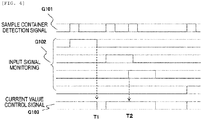
- Fig. 4 is a waveform diagram illustrating a current value control timing of the belt drive motor of the transporting line according to the present embodiment. The waveform is indicated by a high-low two-level signal of as illustrated. If the detection sensor 309 detects the sample container 201, a sample container detection signal G101 becomes high for a predetermined period of time, and the control unit 111 recognizes the detection of the sample container 201.
- control unit 111 performs an input signal monitoring G102 for detecting the sample container 201 by the next detection sensor 309.
- the control unit 111 performs monitoring whenever the detection sensor 309 detects the sample container 201 as illustrated in the sample container detection signal G101.
- the detection sensor 309 does not detect the next sample container 201 within a certain monitoring time after the detection of the sample container 201 by the detection sensor 309, the drive parameter information of which the current value is reduced more than that during the general driving of the belt drive motor 304 from the control unit 111 is sent to the drive control unit 306, the current control unit 307 inside the drive control unit 306 sends a low-level current value controlling signal G103 for setting the current value lower than that as usual to the drive output unit 305 (T1).
- the drive output unit 305 to which the current value controlling signal G103 for installing the current value lower than that as usual is sent converts the current to a current lower than that as usual, sends the current to the belt drive motor 304, and operates the belt drive motor 304.
- the drive parameter information of the current value during the usual driving of the belt drive motor 304 from the control unit 111 is sent to the drive control unit 306, the current control unit 307 inside the drive control unit 306 sets the current value as usual and sends the current value to the drive output unit 305 (T2).
- the drive output unit 305 converts the current to the current as usual, sends the current to the belt drive motor 304, and operates the belt drive motor 304.
- the belt drive motor 304 If the current value flowing through the belt drive motor 304 is caused to be lower than the value flowing as usual, the belt drive motor 304 is driven with the driving force lower than usual, that is, the driving torque lower than usual. In addition, it is recognized that the driving sound of the belt drive motor 304 is reduced by decreasing the driving torque, and thus the noise reduction becomes possible with the transporting line 301.
- the drive control unit 306 that drives a motor such as the belt drive motor 304
- a drive controlling method of a motor using a microcomputer IC called a motor controller is exemplified, and the motor controller may have a function of reducing a current flowing through a general motor called power save.
- the power save by the motor controller is a function of stopping the supply of the current to the corresponding motor or reducing the current value when the corresponding motor controlled by the motor controller stops driving, and is a function different from the function of reducing the current value flowing through the motor during the driving according to the situation, as described above in the present embodiment.
- Fig. 5 illustrates an example of a flowchart illustrating the frequency control of the belt drive motor according to the present embodiment.
- the sample container 201 charged in the sample charging unit 101 of the sample transporting system 100 is started to be transported to the transporting line 301 of the sample transport unit 110 (Step S101) .
- the liquid amount measurement processing unit 104 measures the sample amount of samples that fills the sample container 201 by the processing by each mechanism in each unit such as the centrifugal processing unit 103 (Step S102), the sample amount information is sent to the control unit 111, and the control unit 111 calculates the weight of the corresponding sample container 201 in combination with the container type information of the corresponding sample container 201 transmitted from the sample charging unit 101.
- a plurality of items of drive parameter information such as a value of the driving frequency and a value of the current that drive the belt drive motor 304 according to the weight of the sample container 201 and the length of the transporting line 301 are stored in the storage unit in the control unit 111.
- the drive parameter information is not limited to two types, and three or more types may be used to achieve noise reduction of the sample transporting system by controlling the driving unit in multiple stages.
- control unit 111 uses the plurality of driving frequencies, currents stored in the storage unit and changes the values of driving frequencies, currents in multiple stages according to the number of samples or the amount of samples or according to the number of samples and the amount of samples, to drive the driving unit.
- Step S103 When the detection sensor 309 mounted at a predetermined position of the transporting line 301 detects the sample container 201 (Step S103), the weight of the sample container 201 on the transporting line 301 is compared with a specified value A stored in the control unit 111 (Step S104).
- the drive parameter information of a driving frequency value B stored in the control unit 111 according to the weight specified value A of the sample container 201 is sent to the drive control unit 306, the frequency control unit 308 inside the drive control unit 306 sets the driving frequency of the driving frequency value B and sends the driving frequency to the drive output unit 305, the drive output unit 305 converts the driving frequency to the driving frequency of the driving frequency value B and sends the driving frequency to the belt drive motor 304, and the belt drive motor 304 is operated (Step S105).
- Step S104 if the weight of the sample container 201 is the specified value A or more (NO), the weight of the sample container 201 is compared with a second specified value C stored in the control unit 111 (Step S106). If the weight of the sample container 201 is the specified value C or less (YES), the drive parameter information of a driving frequency value D stored in the control unit 111 according to the weight specified value C of the sample container 201 is sent to the drive control unit 306, and the belt drive motor 304 is operated at the driving frequency of the driving frequency value D in the same manner as in Step S105 (Step S107) .
- Step S106 if the weight of the corresponding sample container 201 is the specified value C or more (NO), the drive parameter information of a driving frequency E stored in the control unit 111 is sent to the drive control unit 306, and the belt drive motor 304 is operated at the driving frequency of a driving frequency value E in the same manner as in Step S105 (Step S108).
- the driving frequency value that drives the belt drive motor 304 is changed based on the weight of the sample container 201 or the length of the transporting line 301 to drive the belt drive motor 304 at different driving frequency values respectively for the plurality of transporting lines 301 with different lengths which are installed in the sample transporting system 100, to shift the driving sound of the belt drive motors 304 and the frequency of the rotating sound of the pulleys 302 or the belt 303 when the belt drive motors 304 are simultaneously driven with the plurality of transporting lines 301, so that the driving sound or the rotating sound in the sample transporting system 100 can be relatively reduced. Accordingly, it is possible to form the operation environment in which the noise is reduced as the sample transporting system 100.
- the reason for providing a specified value by the weight of the sample container 201 is because it is likely that the natural frequency of the transporting line 301 changes according to the weight of the sample container 201 transported on the transporting line 301 to strengthen the driving sound or the rotating sound due to the resonance to the driving frequency value, and thus it is required to set the driving frequency value with respect to the natural frequency of the transporting line 301 including the weight of the sample container 201. Therefore, the weight specified value of the sample container 201 is not necessarily limited to the single sample container 201, but is defined by the sum of the weights of the plurality of sample containers 201 when the plurality of sample containers 201 are transported to the transporting line 301.
- the current value or the driving frequency of the drive motor is changed based on the number and the amount of transported samples to change the driving torque and the driving rotary speed of the transporting line so that noise reduction is achieved by driving the motor under suitable conditions according to the amount and number of the transported samples and by reducing the operation sound of the driving motor or mechanism and the like.
- Fig. 5 illustrates the control processing flow when the frequency of the belt drive motor of the transporting line is controlled, but the current may be controlled by the current control unit, or both of the driving frequency and the current may be controlled by the drive control unit based on the number and the amount of samples, and further the length of the transporting line or the like.
- the above embodiment is specifically described for better understanding of the present invention and is not necessarily limited to include all the configurations of the description.
Landscapes
- Chemical & Material Sciences (AREA)
- Physics & Mathematics (AREA)
- Health & Medical Sciences (AREA)
- Life Sciences & Earth Sciences (AREA)
- Analytical Chemistry (AREA)
- Biochemistry (AREA)
- General Health & Medical Sciences (AREA)
- General Physics & Mathematics (AREA)
- Immunology (AREA)
- Pathology (AREA)
- Chemical Kinetics & Catalysis (AREA)
- Automatic Analysis And Handling Materials Therefor (AREA)
Abstract
Description
- The present invention relates to a sample transporting device, and particularly relates to a sample preprocessing system and a sample transporting technology including an automatic analysis system.
- Examples of a sample processing system that automatically analyzes a sample, which is a biological sample such as blood and urine include a sample preprocessing system that charges or centrifuges a sample, performs a dispensing process, and a labeling process, and an automatic analysis system that analyzes the sample processed in the sample preprocessing system.
- In order to transport the sample to a mechanism that performs a predetermined process or analysis, the sample preprocessing system and the automatic analysis system each include a transporting line of a sample in a technique using a belt conveyer or the like. The plurality of transporting lines are mounted on the sample transporting device to transport the sample to a predetermined mechanism. Examples of a document in the related art relating to such a sample transporting device include
JP-A-2017-167038 - PTL 1:
JP-A-2017-167038 - A transporting line by a belt conveyer technique using a sample transporting device in the related art causes an operation sound of a rotating belt conveyer or a driving sound of a motor that drives the belt conveyer when the belt conveyer operates. Therefore, by simultaneously operating the plurality of connected transporting lines, caused driving sounds or operation sounds are overlapped with each other. According to the number or the weights of the samples transported to the plurality of transporting lines in practice, the size of the caused and overlapped driving sounds or the operation sounds changes. Therefore, a sample transporting technology in which the driving sounds or the operation sounds are reduced indoors where the automatic analysis system or the like is installed to improve the environment when the system is used is required.
- In order to solve the above problem, an object of the present invention is to provide a sample transporting device that can reduce noises or operation sounds, a sample transporting system, and a method of transporting a sample.
- In order to achieve the object, according to the present invention, provided is a sample transporting device including: a transport unit that transports a sample to a predetermined position; a driving unit that drives the transport unit; a drive control unit that controls the driving unit by a driving frequency, current; a detection unit that detects the sample on the transport unit; and a control unit that processes a sample detection signal of the detection unit, in which the control unit outputs a value of driving frequency, current selected based on a result obtained by processing the sample detection signal to the drive control unit and controls so that the driving unit is driven by the selected driving frequency, current, and also a sample transporting system using the sample transporting device.
- Also, in order to achieve the above object, according to the present invention, provided is a method of transporting a sample, including: transporting the sample to a predetermined position by using a transport unit driven by a driving unit controlled by a driving frequency, current, detecting the sample on the transport unit by a detection unit; and performing control so that the driving unit is driven according to a value of the driving frequency, current selected based on a result obtained by processing a sample detection signal of the detection unit by a control unit.
- According to the present invention, noise reduction of the sample transporting device and the system can be achieved by driving the driving unit under suitable conditions according to the amount and number of the transported samples.
-
- [
Fig. 1] Fig. 1 is a diagram illustrating a configuration example of the entire sample transporting system according to Embodiment 1. - [
Fig. 2] Fig. 2 is a cross-sectional view illustrating a configuration example of a sample container used in the sample transporting system according to Embodiment 1. - [
Fig. 3] Fig. 3 is a block diagram illustrating a configuration example of a sample transporting device of Embodiment 1. - [
Fig. 4] Fig. 4 is a waveform diagram illustrating a current value control timing of a belt drive motor according to Embodiment 1. - [
Fig. 5] Fig. 5 is a flowchart illustrating frequency control of a belt drive motor of a transporting line according to Embodiment 1. - An embodiment of the present invention is described in detail with reference to the drawings. It is obvious that, in the following embodiments, the components (including element steps and the like) are not necessarily essential unless otherwise specified or clearly considered to be essential in principle. Further, in all the drawings for explaining the embodiments, the same members are, in principle, denoted by the same reference numerals, and the repeated description thereof is omitted. In the present specification, the expression "driving frequency, current" refers to a driving frequency or a current, or both of a driving frequency and a current.
- Embodiment 1 is an embodiment of a sample transporting device, a system, and a method that include transporting lines . That is, the present embodiment is an embodiment of a sample transporting device including: a transport unit that transports a sample to a predetermined position; a driving unit that drives the transport unit; a drive control unit that controls the driving unit by a driving frequency, current; a detection unit that detects the sample on the transport unit; and a control unit that processes a sample detection signal of the detection unit, in which the control unit outputs a value of driving frequency, current selected based on a result obtained by processing the sample detection signal to the drive control unit and controls so that the driving unit is driven by the selected driving frequency, current, a sample transporting system using the corresponding sample transporting device, and a method of transporting a sample.
- First, with reference to
Figs. 1 and2 , a sample transporting system to which a sample transporting device of Embodiment 1 is applied is described.Fig. 1 is a diagram illustrating one configuration example of the entire sample transporting system according to Embodiment 1, andFig. 2 is a diagram illustrating one configuration example of a sample container used for the sample transporting system of Embodiment 1. - In
Fig. 1 , asample transporting system 100 configures an automatic analysis system that automatically analyzes components of a sample such as blood or urine. Thesample transporting system 100 is configured with a preprocessing unit including mechanisms such as asample charging unit 101, asample storage unit 102, acentrifugal processing unit 103, a liquid amountmeasurement processing unit 104, anopening processing unit 105, a child sample containergeneration processing unit 106, adispensing processing unit 107, and aplugging processing unit 108; asample transport unit 110 that is a sample transporting device that transports a holder on which a plurality ofanalysis processing units 109 that analyzes the sample of asample container 201 subjected to preprocessing and thesample container 201 between each mechanism of the preprocessing unit and theanalysis processing units 109 are mounted; and acontrol unit 111 that controls operations of the entire sample transporting system. - The
sample charging unit 101 of the preprocessing unit is a unit that charges thesample container 201 illustrated inFig. 2 in which the sample is contained, in thesample transporting system 100. In thesample charging unit 101, a sample recognition unit, a plug detection unit, and a sample holder recognition unit which are not illustrated are installed, and thesample charging unit 101 recognizes the container type of the transportedsample container 201 ofFig. 2 , the shape of aplug 202 of the container, and identifier (ID) information given to aholder 203 where thesample container 201 is built, and obtains information that specifies the transportedsample container 201. The sample holder recognition units (not illustrated) are provided in various places inside thesample transporting system 100, and the location of thesample container 201 can be recognized with the sample holder recognition units in each place. - The
centrifugal processing unit 103 is a unit that centrifuges thecharged sample container 201. The liquid amountmeasurement processing unit 104 measures and determines the amount or the color of the sample that fills the transportedsample container 201 with a laser light source unit and an image recognition unit (not illustrated). Theopening processing unit 105 is a unit that opens theplug 202 from thecharged sample container 201. The child sample containergeneration processing unit 106 is a unit that prepares anothersample container 201 required for dispensing the sample contained in thecharged sample container 201 to the nextdispensing processing unit 107 and attaches a barcode or the like thereto. - The
dispensing processing unit 107 is a unit that subdivides a sample to anothersample container 201 prepared in the child sample containergeneration processing unit 106 for analyzing a sample that is not centrifuged or a centrifuged sample with thecentrifugal processing unit 103 with theanalysis processing unit 109 or the like. Theplugging processing unit 108 is a unit that closes theplug 202 into thesample container 201 of which theplug 202 is open or thesample container 201 used for subdivision. According to the type of the plug used for closing thesample container 201, a configuration of thesample transporting system 100 including twoplugging processing units 108 can be provided. - The
analysis processing unit 109 is a unit for transferring the sample processed with each processing unit in thesample transporting system 100 and qualitatively and quantitatively analyzing the component of the sample. Thesample storage unit 102 is a unit that stores thesample container 201 closed with theplugging processing unit 108. - The
sample transport unit 110 is a mechanism that transfers thecharged sample container 201 from thesample charging unit 101 or thesample container 201 used for subdivision to which thedispensing processing unit 107 dispenses the sample, to each unit in thesample transporting system 100 such as thecentrifugal processing unit 103, thedispensing processing unit 107, and theanalysis processing unit 109. Thesample transport unit 110 includes a plurality of transporting lines and is used for transportation to each mechanism unit that performs a predetermined operation in each unit such as thecentrifugal processing unit 103, thedispensing processing unit 107, and theanalysis processing unit 109. Thecontrol unit 111 controls each unit in thesample transporting system 100 and the operation of each mechanism in each unit, and analyzes measurement data in theanalysis processing unit 109. Thecontrol unit 111 communicates with each unit or each mechanism described above, and can recognize the location of the sample in thesample transporting system 100 from the ID information of theholder 203. - As illustrated in
Fig. 2 , thesample container 201 is supported by theholder 203 and transports thesample transport unit 110. Thesample container 201 is sealed with theplug 202 before the opening process with theopening processing unit 105 or after the closing process with theplugging processing unit 108. In addition to the shape for insertion to the inside of thesample container 201 through an opening part on the illustratedsample container 201, theplug 202 has various kinds of shapes such as a screw shape for fixation to thesample container 201 or a seal cap shape for covering the opening part of the upper part of thesample container 201, according to the kind of thesample container 201. In theholder 203, ID information (not illustrated) is embedded, this ID information is detected, so that the location in thesample transporting system 100 can be recognized by thesample charging unit 101 and the sample holder recognition units provided at each place in thesample transporting system 100. - Subsequently, with reference to a block diagram of a portion near the sample transport unit illustrated in
Fig. 3 , one configuration example of the sample transporting device according to the present embodiment is described. InFig. 3 , atransporting line 301 of eachsample transport unit 110 has a structure of providing abelt 303 between a pair ofpulleys 302, installing abelt drive motor 304 on the lower part of thebelt 303, and causing thebelt 303 to rotate between the pair ofpulleys 302 by rotation about an axis part of thebelt drive motor 304. Thebelt 303 rotates clockwise and counterclockwise by thebelt drive motor 304, and thus thesample container 201 can move between thepulleys 302 by being mounted on thebelt 303. - This
transporting line 301 has the length different from each unit or each mechanism in thesample transporting system 100 described above, and the plurality oftransporting lines 301 with different lengths are combined to each other to form thesample transport unit 110 ofFig. 1 that transports thesample container 201 to each unit or each mechanism in thesample transporting system 100. Thecontrol unit 111 is connected to thebelt drive motor 304 via adrive output unit 305 and adrive control unit 306. Thecontrol unit 111 stores drive parameter information such as a current value or a driving frequency value required for driving thebelt drive motor 304 and transmits a predetermined drive parameter to thedrive control unit 306. Thecontrol unit 111 includes a storage unit (memory) (not illustrated) that stores values of a plurality of driving frequencies, currents for driving thedrive motor 304. - The
drive control unit 306 has a structure of including acurrent control unit 307 and afrequency control unit 308 inside thereof, sets a current value or a driving frequency value according to the drive parameter information transmitted from thecontrol unit 111, and sends the values to thedrive output unit 305. Thecurrent control unit 307 and thefrequency control unit 308 may not be separate control unit structures as illustrated but may be one control unit using an integrated circuit such as a central processing unit (CPU) , an Application Specific Integrated Circuit (ASIC), or a Field Programmable Gate Array (FPGA). - The
drive output unit 305 converts a current value or a driving frequency value set for driving thebelt drive motor 304 sent from thedrive control unit 306 to a current or a driving frequency, sends the current or the driving frequency to thebelt drive motor 304, and operates thebelt drive motor 304. - A
detection sensor 309 is mounted on the transportingline 301, and recognizes that thesample container 201 reaches thebelt 303. Thedetection sensor 309 is connected to thecontrol unit 111 via adetection unit 310 and adetection control unit 311. When thesample container 201 reaches thebelt 303, and the sensor detection signal is input to thedetection sensor 309, the sensor detection signal is sent to thedetection unit 310. Thedetection unit 310 sends the sensor detection signal from thedetection sensor 309 to thedetection control unit 311 as the input signal. Thedetection control unit 311 inputs the detection by the corresponding detection sensor of the corresponding transportingline 301 by the input signal which is the sensor detection signal sent from thedetection unit 310, that is, the reaching of thesample container 201 at a desired position, to thecontrol unit 111, as information. Thedrive control unit 306 and thedetection control unit 311 may not be separate control unit structure but may be one control unit structure using a common CPU, a micro IC, or the like. - After the input signal is sent from the
detection unit 310, during the certain period, thecontrol unit 111 has a function of monitoring the input signal sent from thenext detection unit 310, that is, whether thesample container 201 reaches the corresponding transportingline 301, again. Thesample charging unit 101 and the liquid amountmeasurement processing unit 104 in the sample transporting system 100 (not illustrated) are connected to thecontrol unit 111. Therefore, the sample recognition unit of the sample charging unit 101 (not illustrated) can transmit the container type information of the transportedsample container 201 to thecontrol unit 111. The liquid amountmeasurement processing unit 104 measures the amount of the sample that fills the transportedsample container 201 and transmits the result thereof to thecontrol unit 111 as the sample amount information. Thecontrol unit 111 calculates the weight of thecorresponding sample container 201 from the container type information of thecorresponding sample container 201 transmitted from thesample charging unit 101 and the sample amount information of thecorresponding sample container 201 sent from the liquid amountmeasurement processing unit 104. - Subsequently, with respect to
Fig. 4 , the control of the current value of the belt drive motor according to the present embodiment and the effect thereof are described.Fig. 4 is a waveform diagram illustrating a current value control timing of the belt drive motor of the transporting line according to the present embodiment. The waveform is indicated by a high-low two-level signal of as illustrated. If thedetection sensor 309 detects thesample container 201, a sample container detection signal G101 becomes high for a predetermined period of time, and thecontrol unit 111 recognizes the detection of thesample container 201. - At this point, the
control unit 111 performs an input signal monitoring G102 for detecting thesample container 201 by thenext detection sensor 309. Thecontrol unit 111 performs monitoring whenever thedetection sensor 309 detects thesample container 201 as illustrated in the sample container detection signal G101. - If the
detection sensor 309 does not detect thenext sample container 201 within a certain monitoring time after the detection of thesample container 201 by thedetection sensor 309, the drive parameter information of which the current value is reduced more than that during the general driving of thebelt drive motor 304 from thecontrol unit 111 is sent to thedrive control unit 306, thecurrent control unit 307 inside thedrive control unit 306 sends a low-level current value controlling signal G103 for setting the current value lower than that as usual to the drive output unit 305 (T1). Thedrive output unit 305 to which the current value controlling signal G103 for installing the current value lower than that as usual is sent converts the current to a current lower than that as usual, sends the current to thebelt drive motor 304, and operates thebelt drive motor 304. - Meanwhile, after the
detection sensor 309 detects thesample container 201, if thedetection sensor 309 detects thenext sample container 201 within a certain monitoring time by thecontrol unit 111, the drive parameter information of the current value during the usual driving of thebelt drive motor 304 from thecontrol unit 111 is sent to thedrive control unit 306, thecurrent control unit 307 inside thedrive control unit 306 sets the current value as usual and sends the current value to the drive output unit 305 (T2). In this case, thedrive output unit 305 converts the current to the current as usual, sends the current to thebelt drive motor 304, and operates thebelt drive motor 304. - If the current value flowing through the
belt drive motor 304 is caused to be lower than the value flowing as usual, thebelt drive motor 304 is driven with the driving force lower than usual, that is, the driving torque lower than usual. In addition, it is recognized that the driving sound of thebelt drive motor 304 is reduced by decreasing the driving torque, and thus the noise reduction becomes possible with the transportingline 301. - As the
drive control unit 306 that drives a motor such as thebelt drive motor 304, a drive controlling method of a motor using a microcomputer IC called a motor controller is exemplified, and the motor controller may have a function of reducing a current flowing through a general motor called power save. However, in the situation of the device on which the motor is mounted, the power save by the motor controller is a function of stopping the supply of the current to the corresponding motor or reducing the current value when the corresponding motor controlled by the motor controller stops driving, and is a function different from the function of reducing the current value flowing through the motor during the driving according to the situation, as described above in the present embodiment. - Subsequently, with reference to
Fig. 5 , a control processing flow of the frequency control of the belt drive motor which is the driving unit by the drive control unit according to the present embodiment and the effect thereof are described.Fig. 5 illustrates an example of a flowchart illustrating the frequency control of the belt drive motor according to the present embodiment. - The
sample container 201 charged in thesample charging unit 101 of thesample transporting system 100 is started to be transported to the transportingline 301 of the sample transport unit 110 (Step S101) . The liquid amountmeasurement processing unit 104 measures the sample amount of samples that fills thesample container 201 by the processing by each mechanism in each unit such as the centrifugal processing unit 103 (Step S102), the sample amount information is sent to thecontrol unit 111, and thecontrol unit 111 calculates the weight of thecorresponding sample container 201 in combination with the container type information of thecorresponding sample container 201 transmitted from thesample charging unit 101. - A plurality of items of drive parameter information such as a value of the driving frequency and a value of the current that drive the
belt drive motor 304 according to the weight of thesample container 201 and the length of the transportingline 301 are stored in the storage unit in thecontrol unit 111. Here, two types of the weight specified value of thesample container 201 and the driving frequency values according thereto are described. The drive parameter information is not limited to two types, and three or more types may be used to achieve noise reduction of the sample transporting system by controlling the driving unit in multiple stages. That is, thecontrol unit 111 uses the plurality of driving frequencies, currents stored in the storage unit and changes the values of driving frequencies, currents in multiple stages according to the number of samples or the amount of samples or according to the number of samples and the amount of samples, to drive the driving unit. - When the
detection sensor 309 mounted at a predetermined position of the transportingline 301 detects the sample container 201 (Step S103), the weight of thesample container 201 on the transportingline 301 is compared with a specified value A stored in the control unit 111 (Step S104). If the weight of thecorresponding sample container 201 is the specified value A or less (YES), the drive parameter information of a driving frequency value B stored in thecontrol unit 111 according to the weight specified value A of thesample container 201 is sent to thedrive control unit 306, thefrequency control unit 308 inside thedrive control unit 306 sets the driving frequency of the driving frequency value B and sends the driving frequency to thedrive output unit 305, thedrive output unit 305 converts the driving frequency to the driving frequency of the driving frequency value B and sends the driving frequency to thebelt drive motor 304, and thebelt drive motor 304 is operated (Step S105). - Meanwhile, in Step S104, if the weight of the
sample container 201 is the specified value A or more (NO), the weight of thesample container 201 is compared with a second specified value C stored in the control unit 111 (Step S106). If the weight of thesample container 201 is the specified value C or less (YES), the drive parameter information of a driving frequency value D stored in thecontrol unit 111 according to the weight specified value C of thesample container 201 is sent to thedrive control unit 306, and thebelt drive motor 304 is operated at the driving frequency of the driving frequency value D in the same manner as in Step S105 (Step S107) . - In Step S106, if the weight of the
corresponding sample container 201 is the specified value C or more (NO), the drive parameter information of a driving frequency E stored in thecontrol unit 111 is sent to thedrive control unit 306, and thebelt drive motor 304 is operated at the driving frequency of a driving frequency value E in the same manner as in Step S105 (Step S108). - In this manner, the driving frequency value that drives the
belt drive motor 304 is changed based on the weight of thesample container 201 or the length of the transportingline 301 to drive thebelt drive motor 304 at different driving frequency values respectively for the plurality of transportinglines 301 with different lengths which are installed in thesample transporting system 100, to shift the driving sound of thebelt drive motors 304 and the frequency of the rotating sound of thepulleys 302 or thebelt 303 when thebelt drive motors 304 are simultaneously driven with the plurality of transportinglines 301, so that the driving sound or the rotating sound in thesample transporting system 100 can be relatively reduced. Accordingly, it is possible to form the operation environment in which the noise is reduced as thesample transporting system 100. - The reason for providing a specified value by the weight of the
sample container 201 is because it is likely that the natural frequency of the transportingline 301 changes according to the weight of thesample container 201 transported on the transportingline 301 to strengthen the driving sound or the rotating sound due to the resonance to the driving frequency value, and thus it is required to set the driving frequency value with respect to the natural frequency of the transportingline 301 including the weight of thesample container 201. Therefore, the weight specified value of thesample container 201 is not necessarily limited to thesingle sample container 201, but is defined by the sum of the weights of the plurality ofsample containers 201 when the plurality ofsample containers 201 are transported to the transportingline 301. - According to the present invention described above, also with respect to the transporting line, the current value or the driving frequency of the drive motor is changed based on the number and the amount of transported samples to change the driving torque and the driving rotary speed of the transporting line so that noise reduction is achieved by driving the motor under suitable conditions according to the amount and number of the transported samples and by reducing the operation sound of the driving motor or mechanism and the like.
- The present invention is not limited to the above-described examples, but includes various modifications. For example,
Fig. 5 illustrates the control processing flow when the frequency of the belt drive motor of the transporting line is controlled, but the current may be controlled by the current control unit, or both of the driving frequency and the current may be controlled by the drive control unit based on the number and the amount of samples, and further the length of the transporting line or the like. In addition, the above embodiment is specifically described for better understanding of the present invention and is not necessarily limited to include all the configurations of the description. -
- 100: sample transporting system
- 101: sample charging unit
- 102: sample storage unit
- 103: centrifugal processing unit
- 104: liquid amount measurement processing unit
- 105: opening processing unit
- 106: child sample container generation processing unit
- 107: dispensing processing unit
- 108: plugging processing unit
- 109: analysis processing unit
- 110: sample transport unit
- 111: control unit
- 201: sample container
- 202: plug
- 203: holder
- 301: transporting line
- 302: pulley
- 303: belt
- 304: belt drive motor
- 305: drive output unit
- 306: drive control unit
- 307: current control unit
- 308: frequency control unit
- 309: detection sensor
- 310: detection unit
- 311: detection control unit
Claims (15)
- A sample transporting device comprising:a transport unit that transports a sample to a predetermined position;a driving unit that drives the transport unit;a drive control unit that controls the driving unit by a driving frequency, current;a detection unit that detects the sample on the transport unit; anda control unit that processes a sample detection signal of the detection unit, whereinthe control unitoutputs a value of driving frequency, current selected based on a result obtained by processing the sample detection signal to the drive control unit and controls so that the driving unit is driven by the corresponding driving frequency, current.
- The sample transporting device according to claim 1, wherein
the control unit
processes the sample detection signal, calculates the number of samples on the transport unit, and selects the driving frequency, current based on the number of samples. - The sample transporting device according to claim 2, comprising:a sample amount measurement unit that measures the amount of the sample, whereinthe control unitselects a value of the driving frequency, current based on the number or a measured amount of samples on the transport unit or based on the number and the amount of samples.
- The sample transporting device according to claim 3, wherein
the control unit includes
a storage unit that stores values of the plurality of driving frequencies, currents. - The sample transporting device according to claim 4, wherein
the control unit
uses the plurality of stored driving frequencies, currents, changes the values of the driving frequencies, currents in multiple stages according to the number or the amount of samples, or the number and the amount of samples to drive the driving unit. - The sample transporting device according to claim 4, wherein
the control unit
selects one of the plurality of stored driving frequencies based on whether the amount of samples is more or less than a specified value. - The sample transporting device according to claim 4, wherein
the control unit
selects one of the stored values of the currents based on whether the amount of samples is more or less than a specified value. - A sample transporting system comprising:a preprocessing unit that preprocesses the sample;an analysis processing unit that analyzes the sample subjected to the preprocessing; andthe sample transporting device according to any one of claims 1 to 7 that transports the sample between the preprocessing unit and the analysis processing unit.
- A method of transporting a sample, comprising:transporting the sample to a predetermined position by using a transport unit driven by a driving unit controlled by a driving frequency, current,detecting the sample on the transport unit by a detection unit; andperforming control so that the driving unit is driven according to a value of the driving frequency, current selected based on a result obtained by processing a sample detection signal of the detection unit by a control unit.
- The method of transporting a sample, according to claim 9, wherein
the control unit
processes the sample detection signal, calculates the number of samples on the transport unit, and selects the driving frequency, current based on the number of samples. - The method of transporting a sample, according to claim 10, wherein
the control unit
selects a value of the driving frequency, current for driving the driving unit from the values of the plurality of driving frequencies, currents stored inside. - The method of transporting a sample according to claim 11, further comprising:measuring an amount of the sample, whereinthe control unitselects a value of the driving frequency, current for driving the driving unit based on the number and the measured amount of samples on the transport unit.
- The method of transporting a sample according to claim 12, wherein
the control unit
uses the plurality of driving frequencies, currents stored inside, changes the values of the driving frequencies, currents according to the number or the amount of samples or the number and the amount of samples in multiple stages to drive the driving unit. - The method of transporting a sample according to claim 13, wherein
the control unit
selects one of the plurality of stored driving frequencies based on whether the amount of samples is more or less than a specified value. - The method of transporting a sample according to claim 13, wherein
the control unit
selects one of the values of the plurality of stored currents based on whether the amount of samples is more or less than a specified value.
Applications Claiming Priority (2)
| Application Number | Priority Date | Filing Date | Title |
|---|---|---|---|
| JP2018181723 | 2018-09-27 | ||
| PCT/JP2019/037176 WO2020066965A1 (en) | 2018-09-27 | 2019-09-24 | Sample transporting device, system and method |
Publications (3)
| Publication Number | Publication Date |
|---|---|
| EP3859345A1 true EP3859345A1 (en) | 2021-08-04 |
| EP3859345A4 EP3859345A4 (en) | 2022-07-20 |
| EP3859345B1 EP3859345B1 (en) | 2024-04-24 |
Family
ID=69950717
Family Applications (1)
| Application Number | Title | Priority Date | Filing Date |
|---|---|---|---|
| EP19867485.5A Active EP3859345B1 (en) | 2018-09-27 | 2019-09-24 | Sample transporting device, system and method |
Country Status (5)
| Country | Link |
|---|---|
| US (1) | US12306195B2 (en) |
| EP (1) | EP3859345B1 (en) |
| JP (1) | JP7191971B2 (en) |
| CN (1) | CN112703405B (en) |
| WO (1) | WO2020066965A1 (en) |
Families Citing this family (1)
| Publication number | Priority date | Publication date | Assignee | Title |
|---|---|---|---|---|
| EP4335799A4 (en) * | 2021-05-06 | 2025-05-14 | Hitachi High-Tech Corporation | Specimen transport device, specimen analysis system, and specimen pretreatment system |
Family Cites Families (15)
| Publication number | Priority date | Publication date | Assignee | Title |
|---|---|---|---|---|
| FR2666316B1 (en) * | 1990-09-04 | 1992-12-11 | France Etat | DEVICE FOR CONTROLLING A FLOW OF OBJECTS IN CONTINUOUSLY RUNNING, ESPECIALLY PACKAGES OR PACKAGES. |
| JPH06308134A (en) * | 1993-04-27 | 1994-11-04 | Toshiba Corp | Apparatus for injecting reagent |
| US6471039B1 (en) * | 1997-12-12 | 2002-10-29 | Crisplant A/S | Conveyor system and a method for operating same |
| CN2579870Y (en) * | 2002-11-08 | 2003-10-15 | 毕春光 | Electronic program control PVC automatic forming oral administration liquid filler |
| JP4538365B2 (en) | 2005-04-25 | 2010-09-08 | 株式会社日立ハイテクノロジーズ | Reagent cooler and automatic analyzer equipped with the same |
| JP2007108062A (en) * | 2005-10-14 | 2007-04-26 | Olympus Corp | Agitator, container, and analyzer |
| JP4618215B2 (en) | 2006-08-23 | 2011-01-26 | 和光純薬工業株式会社 | Dispensing device and dispensing method |
| JP2010217048A (en) * | 2009-03-17 | 2010-09-30 | Beckman Coulter Inc | Stirring device, autoanalyzer, and stirring method |
| JP2013190388A (en) | 2012-03-15 | 2013-09-26 | Beckman Coulter Inc | Automatic analyzer and analysis method |
| US9470510B2 (en) * | 2012-03-29 | 2016-10-18 | Biomerieux, Inc. | Systems and methods for detecting fallen containers suitable for apparatus for automated evaluation of microorganism growth in test samples |
| JP6065803B2 (en) | 2013-10-07 | 2017-01-25 | 株式会社島津製作所 | Automatic analysis system connecting multiple analyzers |
| CN104692090A (en) * | 2015-02-13 | 2015-06-10 | 江苏新美星包装机械股份有限公司 | Blank storage hopper for bottle blank hoister |
| JP6401630B2 (en) * | 2015-02-24 | 2018-10-10 | 株式会社日立ハイテクノロジーズ | Sample test automation system and sample check method |
| CN105217271B (en) * | 2015-08-31 | 2017-09-01 | 西安华光信息技术有限责任公司 | Adaptive Control Method of Belt Transportation System Based on Video Recognition |
| JP6668123B2 (en) | 2016-03-17 | 2020-03-18 | 株式会社日立ハイテク | Sample transport system |
-
2019
- 2019-09-24 JP JP2020549187A patent/JP7191971B2/en active Active
- 2019-09-24 CN CN201980054936.3A patent/CN112703405B/en active Active
- 2019-09-24 WO PCT/JP2019/037176 patent/WO2020066965A1/en not_active Ceased
- 2019-09-24 EP EP19867485.5A patent/EP3859345B1/en active Active
- 2019-09-24 US US17/280,575 patent/US12306195B2/en active Active
Also Published As
| Publication number | Publication date |
|---|---|
| JP7191971B2 (en) | 2022-12-19 |
| WO2020066965A1 (en) | 2020-04-02 |
| CN112703405A (en) | 2021-04-23 |
| US12306195B2 (en) | 2025-05-20 |
| EP3859345B1 (en) | 2024-04-24 |
| CN112703405B (en) | 2024-07-23 |
| EP3859345A4 (en) | 2022-07-20 |
| US20220034920A1 (en) | 2022-02-03 |
| JPWO2020066965A1 (en) | 2021-11-25 |
Similar Documents
| Publication | Publication Date | Title |
|---|---|---|
| JP3883611B2 (en) | Elevator door control device | |
| EP3527991B1 (en) | Automatic analyzer | |
| EP3859345B1 (en) | Sample transporting device, system and method | |
| EP3424604A2 (en) | Method of in-line testing devices and testing apparatus | |
| JP5568633B2 (en) | Elevator door control device | |
| CN112537738B (en) | Capping device and method for closing screw caps | |
| JP6999823B2 (en) | Abnormality diagnostic device | |
| US9963934B2 (en) | Device and method for controlling speed of rolling door | |
| EP4244976A1 (en) | Monitoring device for monitoring an electric motor in a laboratory system | |
| WO2020201330A1 (en) | Power meter based monitoring of elevator usage | |
| EP3745149A1 (en) | Power conversion device, rotating machine system using same, and diagnosis method for same | |
| CN105628946B (en) | The feedway and method of a kind of container | |
| JPH1081474A (en) | Elevator door diagnostics | |
| US6335603B1 (en) | Motor control circuit and control system using the same | |
| US3895278A (en) | Rotor acceleration control circuit | |
| CN212903876U (en) | Automatic cover closing calibration system | |
| CN106289846B (en) | A test device for an intelligent environmental protection barrel | |
| KR101302566B1 (en) | System and method for controlling roof for vehicle | |
| JPH02310284A (en) | Abnormality detecting method for elevator door | |
| CN116047434B (en) | Microwave testing method and system | |
| CN106840803B (en) | Centrifuge identification error correction system and method | |
| CN116413465A (en) | Cup organizer and control method | |
| WO2017002810A1 (en) | Weighing apparatus | |
| JP5710327B2 (en) | Elevator door opening / closing control device, elevator door opening / closing control method, and elevator door opening / closing control program | |
| WO2010015502A2 (en) | Device for increasing quality control during a seaming process |
Legal Events
| Date | Code | Title | Description |
|---|---|---|---|
| STAA | Information on the status of an ep patent application or granted ep patent |
Free format text: STATUS: THE INTERNATIONAL PUBLICATION HAS BEEN MADE |
|
| PUAI | Public reference made under article 153(3) epc to a published international application that has entered the european phase |
Free format text: ORIGINAL CODE: 0009012 |
|
| STAA | Information on the status of an ep patent application or granted ep patent |
Free format text: STATUS: REQUEST FOR EXAMINATION WAS MADE |
|
| 17P | Request for examination filed |
Effective date: 20210428 |
|
| AK | Designated contracting states |
Kind code of ref document: A1 Designated state(s): AL AT BE BG CH CY CZ DE DK EE ES FI FR GB GR HR HU IE IS IT LI LT LU LV MC MK MT NL NO PL PT RO RS SE SI SK SM TR |
|
| DAV | Request for validation of the european patent (deleted) | ||
| DAX | Request for extension of the european patent (deleted) | ||
| A4 | Supplementary search report drawn up and despatched |
Effective date: 20220615 |
|
| RIC1 | Information provided on ipc code assigned before grant |
Ipc: B65G 43/08 20060101ALI20220611BHEP Ipc: G01N 35/00 20060101ALI20220611BHEP Ipc: G01N 35/02 20060101ALI20220611BHEP Ipc: G01N 35/04 20060101AFI20220611BHEP |
|
| GRAP | Despatch of communication of intention to grant a patent |
Free format text: ORIGINAL CODE: EPIDOSNIGR1 |
|
| STAA | Information on the status of an ep patent application or granted ep patent |
Free format text: STATUS: GRANT OF PATENT IS INTENDED |
|
| INTG | Intention to grant announced |
Effective date: 20231201 |
|
| GRAS | Grant fee paid |
Free format text: ORIGINAL CODE: EPIDOSNIGR3 |
|
| GRAA | (expected) grant |
Free format text: ORIGINAL CODE: 0009210 |
|
| STAA | Information on the status of an ep patent application or granted ep patent |
Free format text: STATUS: THE PATENT HAS BEEN GRANTED |
|
| AK | Designated contracting states |
Kind code of ref document: B1 Designated state(s): AL AT BE BG CH CY CZ DE DK EE ES FI FR GB GR HR HU IE IS IT LI LT LU LV MC MK MT NL NO PL PT RO RS SE SI SK SM TR |
|
| REG | Reference to a national code |
Ref country code: GB Ref legal event code: FG4D |
|
| REG | Reference to a national code |
Ref country code: CH Ref legal event code: EP |
|
| REG | Reference to a national code |
Ref country code: DE Ref legal event code: R096 Ref document number: 602019051085 Country of ref document: DE |
|
| REG | Reference to a national code |
Ref country code: IE Ref legal event code: FG4D |
|
| REG | Reference to a national code |
Ref country code: LT Ref legal event code: MG9D |
|
| REG | Reference to a national code |
Ref country code: NL Ref legal event code: MP Effective date: 20240424 |
|
| REG | Reference to a national code |
Ref country code: AT Ref legal event code: MK05 Ref document number: 1680126 Country of ref document: AT Kind code of ref document: T Effective date: 20240424 |
|
| PG25 | Lapsed in a contracting state [announced via postgrant information from national office to epo] |
Ref country code: NL Free format text: LAPSE BECAUSE OF FAILURE TO SUBMIT A TRANSLATION OF THE DESCRIPTION OR TO PAY THE FEE WITHIN THE PRESCRIBED TIME-LIMIT Effective date: 20240424 |
|
| PG25 | Lapsed in a contracting state [announced via postgrant information from national office to epo] |
Ref country code: NL Free format text: LAPSE BECAUSE OF FAILURE TO SUBMIT A TRANSLATION OF THE DESCRIPTION OR TO PAY THE FEE WITHIN THE PRESCRIBED TIME-LIMIT Effective date: 20240424 |
|
| PG25 | Lapsed in a contracting state [announced via postgrant information from national office to epo] |
Ref country code: IS Free format text: LAPSE BECAUSE OF FAILURE TO SUBMIT A TRANSLATION OF THE DESCRIPTION OR TO PAY THE FEE WITHIN THE PRESCRIBED TIME-LIMIT Effective date: 20240824 |
|
| PG25 | Lapsed in a contracting state [announced via postgrant information from national office to epo] |
Ref country code: BG Free format text: LAPSE BECAUSE OF FAILURE TO SUBMIT A TRANSLATION OF THE DESCRIPTION OR TO PAY THE FEE WITHIN THE PRESCRIBED TIME-LIMIT Effective date: 20240424 |
|
| PG25 | Lapsed in a contracting state [announced via postgrant information from national office to epo] |
Ref country code: HR Free format text: LAPSE BECAUSE OF FAILURE TO SUBMIT A TRANSLATION OF THE DESCRIPTION OR TO PAY THE FEE WITHIN THE PRESCRIBED TIME-LIMIT Effective date: 20240424 Ref country code: FI Free format text: LAPSE BECAUSE OF FAILURE TO SUBMIT A TRANSLATION OF THE DESCRIPTION OR TO PAY THE FEE WITHIN THE PRESCRIBED TIME-LIMIT Effective date: 20240424 |
|
| PG25 | Lapsed in a contracting state [announced via postgrant information from national office to epo] |
Ref country code: GR Free format text: LAPSE BECAUSE OF FAILURE TO SUBMIT A TRANSLATION OF THE DESCRIPTION OR TO PAY THE FEE WITHIN THE PRESCRIBED TIME-LIMIT Effective date: 20240725 |
|
| PG25 | Lapsed in a contracting state [announced via postgrant information from national office to epo] |
Ref country code: PT Free format text: LAPSE BECAUSE OF FAILURE TO SUBMIT A TRANSLATION OF THE DESCRIPTION OR TO PAY THE FEE WITHIN THE PRESCRIBED TIME-LIMIT Effective date: 20240826 |
|
| PG25 | Lapsed in a contracting state [announced via postgrant information from national office to epo] |
Ref country code: ES Free format text: LAPSE BECAUSE OF FAILURE TO SUBMIT A TRANSLATION OF THE DESCRIPTION OR TO PAY THE FEE WITHIN THE PRESCRIBED TIME-LIMIT Effective date: 20240424 |
|
| PG25 | Lapsed in a contracting state [announced via postgrant information from national office to epo] |
Ref country code: AT Free format text: LAPSE BECAUSE OF FAILURE TO SUBMIT A TRANSLATION OF THE DESCRIPTION OR TO PAY THE FEE WITHIN THE PRESCRIBED TIME-LIMIT Effective date: 20240424 |
|
| PG25 | Lapsed in a contracting state [announced via postgrant information from national office to epo] |
Ref country code: PL Free format text: LAPSE BECAUSE OF FAILURE TO SUBMIT A TRANSLATION OF THE DESCRIPTION OR TO PAY THE FEE WITHIN THE PRESCRIBED TIME-LIMIT Effective date: 20240424 |
|
| PG25 | Lapsed in a contracting state [announced via postgrant information from national office to epo] |
Ref country code: LV Free format text: LAPSE BECAUSE OF FAILURE TO SUBMIT A TRANSLATION OF THE DESCRIPTION OR TO PAY THE FEE WITHIN THE PRESCRIBED TIME-LIMIT Effective date: 20240424 |
|
| PG25 | Lapsed in a contracting state [announced via postgrant information from national office to epo] |
Ref country code: PT Free format text: LAPSE BECAUSE OF FAILURE TO SUBMIT A TRANSLATION OF THE DESCRIPTION OR TO PAY THE FEE WITHIN THE PRESCRIBED TIME-LIMIT Effective date: 20240826 Ref country code: PL Free format text: LAPSE BECAUSE OF FAILURE TO SUBMIT A TRANSLATION OF THE DESCRIPTION OR TO PAY THE FEE WITHIN THE PRESCRIBED TIME-LIMIT Effective date: 20240424 Ref country code: NO Free format text: LAPSE BECAUSE OF FAILURE TO SUBMIT A TRANSLATION OF THE DESCRIPTION OR TO PAY THE FEE WITHIN THE PRESCRIBED TIME-LIMIT Effective date: 20240724 Ref country code: LV Free format text: LAPSE BECAUSE OF FAILURE TO SUBMIT A TRANSLATION OF THE DESCRIPTION OR TO PAY THE FEE WITHIN THE PRESCRIBED TIME-LIMIT Effective date: 20240424 Ref country code: IS Free format text: LAPSE BECAUSE OF FAILURE TO SUBMIT A TRANSLATION OF THE DESCRIPTION OR TO PAY THE FEE WITHIN THE PRESCRIBED TIME-LIMIT Effective date: 20240824 Ref country code: HR Free format text: LAPSE BECAUSE OF FAILURE TO SUBMIT A TRANSLATION OF THE DESCRIPTION OR TO PAY THE FEE WITHIN THE PRESCRIBED TIME-LIMIT Effective date: 20240424 Ref country code: GR Free format text: LAPSE BECAUSE OF FAILURE TO SUBMIT A TRANSLATION OF THE DESCRIPTION OR TO PAY THE FEE WITHIN THE PRESCRIBED TIME-LIMIT Effective date: 20240725 Ref country code: FI Free format text: LAPSE BECAUSE OF FAILURE TO SUBMIT A TRANSLATION OF THE DESCRIPTION OR TO PAY THE FEE WITHIN THE PRESCRIBED TIME-LIMIT Effective date: 20240424 Ref country code: ES Free format text: LAPSE BECAUSE OF FAILURE TO SUBMIT A TRANSLATION OF THE DESCRIPTION OR TO PAY THE FEE WITHIN THE PRESCRIBED TIME-LIMIT Effective date: 20240424 Ref country code: BG Free format text: LAPSE BECAUSE OF FAILURE TO SUBMIT A TRANSLATION OF THE DESCRIPTION OR TO PAY THE FEE WITHIN THE PRESCRIBED TIME-LIMIT Effective date: 20240424 Ref country code: AT Free format text: LAPSE BECAUSE OF FAILURE TO SUBMIT A TRANSLATION OF THE DESCRIPTION OR TO PAY THE FEE WITHIN THE PRESCRIBED TIME-LIMIT Effective date: 20240424 Ref country code: RS Free format text: LAPSE BECAUSE OF FAILURE TO SUBMIT A TRANSLATION OF THE DESCRIPTION OR TO PAY THE FEE WITHIN THE PRESCRIBED TIME-LIMIT Effective date: 20240724 |
|
| PG25 | Lapsed in a contracting state [announced via postgrant information from national office to epo] |
Ref country code: DK Free format text: LAPSE BECAUSE OF FAILURE TO SUBMIT A TRANSLATION OF THE DESCRIPTION OR TO PAY THE FEE WITHIN THE PRESCRIBED TIME-LIMIT Effective date: 20240424 |
|
| PG25 | Lapsed in a contracting state [announced via postgrant information from national office to epo] |
Ref country code: EE Free format text: LAPSE BECAUSE OF FAILURE TO SUBMIT A TRANSLATION OF THE DESCRIPTION OR TO PAY THE FEE WITHIN THE PRESCRIBED TIME-LIMIT Effective date: 20240424 |
|
| PG25 | Lapsed in a contracting state [announced via postgrant information from national office to epo] |
Ref country code: CZ Free format text: LAPSE BECAUSE OF FAILURE TO SUBMIT A TRANSLATION OF THE DESCRIPTION OR TO PAY THE FEE WITHIN THE PRESCRIBED TIME-LIMIT Effective date: 20240424 |
|
| PG25 | Lapsed in a contracting state [announced via postgrant information from national office to epo] |
Ref country code: SK Free format text: LAPSE BECAUSE OF FAILURE TO SUBMIT A TRANSLATION OF THE DESCRIPTION OR TO PAY THE FEE WITHIN THE PRESCRIBED TIME-LIMIT Effective date: 20240424 Ref country code: RO Free format text: LAPSE BECAUSE OF FAILURE TO SUBMIT A TRANSLATION OF THE DESCRIPTION OR TO PAY THE FEE WITHIN THE PRESCRIBED TIME-LIMIT Effective date: 20240424 |
|
| REG | Reference to a national code |
Ref country code: DE Ref legal event code: R097 Ref document number: 602019051085 Country of ref document: DE |
|
| PG25 | Lapsed in a contracting state [announced via postgrant information from national office to epo] |
Ref country code: SM Free format text: LAPSE BECAUSE OF FAILURE TO SUBMIT A TRANSLATION OF THE DESCRIPTION OR TO PAY THE FEE WITHIN THE PRESCRIBED TIME-LIMIT Effective date: 20240424 |
|
| PG25 | Lapsed in a contracting state [announced via postgrant information from national office to epo] |
Ref country code: SM Free format text: LAPSE BECAUSE OF FAILURE TO SUBMIT A TRANSLATION OF THE DESCRIPTION OR TO PAY THE FEE WITHIN THE PRESCRIBED TIME-LIMIT Effective date: 20240424 Ref country code: SK Free format text: LAPSE BECAUSE OF FAILURE TO SUBMIT A TRANSLATION OF THE DESCRIPTION OR TO PAY THE FEE WITHIN THE PRESCRIBED TIME-LIMIT Effective date: 20240424 Ref country code: RO Free format text: LAPSE BECAUSE OF FAILURE TO SUBMIT A TRANSLATION OF THE DESCRIPTION OR TO PAY THE FEE WITHIN THE PRESCRIBED TIME-LIMIT Effective date: 20240424 Ref country code: EE Free format text: LAPSE BECAUSE OF FAILURE TO SUBMIT A TRANSLATION OF THE DESCRIPTION OR TO PAY THE FEE WITHIN THE PRESCRIBED TIME-LIMIT Effective date: 20240424 Ref country code: DK Free format text: LAPSE BECAUSE OF FAILURE TO SUBMIT A TRANSLATION OF THE DESCRIPTION OR TO PAY THE FEE WITHIN THE PRESCRIBED TIME-LIMIT Effective date: 20240424 Ref country code: CZ Free format text: LAPSE BECAUSE OF FAILURE TO SUBMIT A TRANSLATION OF THE DESCRIPTION OR TO PAY THE FEE WITHIN THE PRESCRIBED TIME-LIMIT Effective date: 20240424 |
|
| PLBE | No opposition filed within time limit |
Free format text: ORIGINAL CODE: 0009261 |
|
| STAA | Information on the status of an ep patent application or granted ep patent |
Free format text: STATUS: NO OPPOSITION FILED WITHIN TIME LIMIT |
|
| 26N | No opposition filed |
Effective date: 20250127 |
|
| PG25 | Lapsed in a contracting state [announced via postgrant information from national office to epo] |
Ref country code: SI Free format text: LAPSE BECAUSE OF FAILURE TO SUBMIT A TRANSLATION OF THE DESCRIPTION OR TO PAY THE FEE WITHIN THE PRESCRIBED TIME-LIMIT Effective date: 20240424 Ref country code: MC Free format text: LAPSE BECAUSE OF FAILURE TO SUBMIT A TRANSLATION OF THE DESCRIPTION OR TO PAY THE FEE WITHIN THE PRESCRIBED TIME-LIMIT Effective date: 20240424 |
|
| REG | Reference to a national code |
Ref country code: CH Ref legal event code: PL |
|
| PG25 | Lapsed in a contracting state [announced via postgrant information from national office to epo] |
Ref country code: LU Free format text: LAPSE BECAUSE OF NON-PAYMENT OF DUE FEES Effective date: 20240924 |
|
| GBPC | Gb: european patent ceased through non-payment of renewal fee |
Effective date: 20240924 |
|
| PG25 | Lapsed in a contracting state [announced via postgrant information from national office to epo] |
Ref country code: GB Free format text: LAPSE BECAUSE OF NON-PAYMENT OF DUE FEES Effective date: 20240924 |
|
| REG | Reference to a national code |
Ref country code: BE Ref legal event code: MM Effective date: 20240930 |
|
| PG25 | Lapsed in a contracting state [announced via postgrant information from national office to epo] |
Ref country code: BE Free format text: LAPSE BECAUSE OF NON-PAYMENT OF DUE FEES Effective date: 20240930 |
|
| PG25 | Lapsed in a contracting state [announced via postgrant information from national office to epo] |
Ref country code: CH Free format text: LAPSE BECAUSE OF NON-PAYMENT OF DUE FEES Effective date: 20240930 |
|
| PG25 | Lapsed in a contracting state [announced via postgrant information from national office to epo] |
Ref country code: IE Free format text: LAPSE BECAUSE OF NON-PAYMENT OF DUE FEES Effective date: 20240924 |
|
| PG25 | Lapsed in a contracting state [announced via postgrant information from national office to epo] |
Ref country code: SE Free format text: LAPSE BECAUSE OF FAILURE TO SUBMIT A TRANSLATION OF THE DESCRIPTION OR TO PAY THE FEE WITHIN THE PRESCRIBED TIME-LIMIT Effective date: 20240424 |
|
| PGFP | Annual fee paid to national office [announced via postgrant information from national office to epo] |
Ref country code: DE Payment date: 20250827 Year of fee payment: 7 |
|
| PGFP | Annual fee paid to national office [announced via postgrant information from national office to epo] |
Ref country code: FR Payment date: 20250925 Year of fee payment: 7 |
|
| PG25 | Lapsed in a contracting state [announced via postgrant information from national office to epo] |
Ref country code: CY Free format text: LAPSE BECAUSE OF FAILURE TO SUBMIT A TRANSLATION OF THE DESCRIPTION OR TO PAY THE FEE WITHIN THE PRESCRIBED TIME-LIMIT; INVALID AB INITIO Effective date: 20190924 Ref country code: IT Free format text: LAPSE BECAUSE OF FAILURE TO SUBMIT A TRANSLATION OF THE DESCRIPTION OR TO PAY THE FEE WITHIN THE PRESCRIBED TIME-LIMIT Effective date: 20240424 |
|
| PG25 | Lapsed in a contracting state [announced via postgrant information from national office to epo] |
Ref country code: HU Free format text: LAPSE BECAUSE OF FAILURE TO SUBMIT A TRANSLATION OF THE DESCRIPTION OR TO PAY THE FEE WITHIN THE PRESCRIBED TIME-LIMIT; INVALID AB INITIO Effective date: 20190924 |
|
| PG25 | Lapsed in a contracting state [announced via postgrant information from national office to epo] |
Ref country code: TR Free format text: LAPSE BECAUSE OF FAILURE TO SUBMIT A TRANSLATION OF THE DESCRIPTION OR TO PAY THE FEE WITHIN THE PRESCRIBED TIME-LIMIT Effective date: 20240424 |
|
| PG25 | Lapsed in a contracting state [announced via postgrant information from national office to epo] |
Ref country code: LT Free format text: LAPSE BECAUSE OF FAILURE TO SUBMIT A TRANSLATION OF THE DESCRIPTION OR TO PAY THE FEE WITHIN THE PRESCRIBED TIME-LIMIT Effective date: 20240424 |