EP3859298A1 - Wheel aligner-based method for aligning calibration device with vehicle and calibration system - Google Patents
Wheel aligner-based method for aligning calibration device with vehicle and calibration system Download PDFInfo
- Publication number
- EP3859298A1 EP3859298A1 EP19902819.2A EP19902819A EP3859298A1 EP 3859298 A1 EP3859298 A1 EP 3859298A1 EP 19902819 A EP19902819 A EP 19902819A EP 3859298 A1 EP3859298 A1 EP 3859298A1
- Authority
- EP
- European Patent Office
- Prior art keywords
- calibration device
- vehicle
- image sensor
- image
- computer
- Prior art date
- Legal status (The legal status is an assumption and is not a legal conclusion. Google has not performed a legal analysis and makes no representation as to the accuracy of the status listed.)
- Granted
Links
Images




Classifications
-
- G—PHYSICS
- G01—MEASURING; TESTING
- G01B—MEASURING LENGTH, THICKNESS OR SIMILAR LINEAR DIMENSIONS; MEASURING ANGLES; MEASURING AREAS; MEASURING IRREGULARITIES OF SURFACES OR CONTOURS
- G01B11/00—Measuring arrangements characterised by the use of optical techniques
- G01B11/26—Measuring arrangements characterised by the use of optical techniques for measuring angles or tapers; for testing the alignment of axes
- G01B11/27—Measuring arrangements characterised by the use of optical techniques for measuring angles or tapers; for testing the alignment of axes for testing the alignment of axes
- G01B11/272—Measuring arrangements characterised by the use of optical techniques for measuring angles or tapers; for testing the alignment of axes for testing the alignment of axes using photoelectric detection means
-
- G—PHYSICS
- G01—MEASURING; TESTING
- G01M—TESTING STATIC OR DYNAMIC BALANCE OF MACHINES OR STRUCTURES; TESTING OF STRUCTURES OR APPARATUS, NOT OTHERWISE PROVIDED FOR
- G01M17/00—Testing of vehicles
- G01M17/007—Wheeled or endless-tracked vehicles
- G01M17/013—Wheels
-
- G—PHYSICS
- G06—COMPUTING OR CALCULATING; COUNTING
- G06T—IMAGE DATA PROCESSING OR GENERATION, IN GENERAL
- G06T7/00—Image analysis
- G06T7/70—Determining position or orientation of objects or cameras
- G06T7/73—Determining position or orientation of objects or cameras using feature-based methods
-
- G—PHYSICS
- G06—COMPUTING OR CALCULATING; COUNTING
- G06T—IMAGE DATA PROCESSING OR GENERATION, IN GENERAL
- G06T7/00—Image analysis
- G06T7/70—Determining position or orientation of objects or cameras
- G06T7/73—Determining position or orientation of objects or cameras using feature-based methods
- G06T7/74—Determining position or orientation of objects or cameras using feature-based methods involving reference images or patches
-
- G—PHYSICS
- G06—COMPUTING OR CALCULATING; COUNTING
- G06T—IMAGE DATA PROCESSING OR GENERATION, IN GENERAL
- G06T7/00—Image analysis
- G06T7/80—Analysis of captured images to determine intrinsic or extrinsic camera parameters, i.e. camera calibration
-
- H—ELECTRICITY
- H04—ELECTRIC COMMUNICATION TECHNIQUE
- H04N—PICTORIAL COMMUNICATION, e.g. TELEVISION
- H04N23/00—Cameras or camera modules comprising electronic image sensors; Control thereof
- H04N23/90—Arrangement of cameras or camera modules, e.g. multiple cameras in TV studios or sports stadiums
-
- G—PHYSICS
- G01—MEASURING; TESTING
- G01B—MEASURING LENGTH, THICKNESS OR SIMILAR LINEAR DIMENSIONS; MEASURING ANGLES; MEASURING AREAS; MEASURING IRREGULARITIES OF SURFACES OR CONTOURS
- G01B11/00—Measuring arrangements characterised by the use of optical techniques
- G01B11/26—Measuring arrangements characterised by the use of optical techniques for measuring angles or tapers; for testing the alignment of axes
- G01B11/275—Measuring arrangements characterised by the use of optical techniques for measuring angles or tapers; for testing the alignment of axes for testing wheel alignment
- G01B11/2755—Measuring arrangements characterised by the use of optical techniques for measuring angles or tapers; for testing the alignment of axes for testing wheel alignment using photoelectric detection means
-
- G—PHYSICS
- G01—MEASURING; TESTING
- G01B—MEASURING LENGTH, THICKNESS OR SIMILAR LINEAR DIMENSIONS; MEASURING ANGLES; MEASURING AREAS; MEASURING IRREGULARITIES OF SURFACES OR CONTOURS
- G01B2210/00—Aspects not specifically covered by any group under G01B, e.g. of wheel alignment, caliper-like sensors
- G01B2210/10—Wheel alignment
- G01B2210/14—One or more cameras or other optical devices capable of acquiring a two-dimensional image
- G01B2210/143—One or more cameras on each side of a vehicle in the main embodiment
-
- G—PHYSICS
- G01—MEASURING; TESTING
- G01B—MEASURING LENGTH, THICKNESS OR SIMILAR LINEAR DIMENSIONS; MEASURING ANGLES; MEASURING AREAS; MEASURING IRREGULARITIES OF SURFACES OR CONTOURS
- G01B2210/00—Aspects not specifically covered by any group under G01B, e.g. of wheel alignment, caliper-like sensors
- G01B2210/10—Wheel alignment
- G01B2210/30—Reference markings, reflector, scale or other passive device
-
- G—PHYSICS
- G01—MEASURING; TESTING
- G01B—MEASURING LENGTH, THICKNESS OR SIMILAR LINEAR DIMENSIONS; MEASURING ANGLES; MEASURING AREAS; MEASURING IRREGULARITIES OF SURFACES OR CONTOURS
- G01B2210/00—Aspects not specifically covered by any group under G01B, e.g. of wheel alignment, caliper-like sensors
- G01B2210/10—Wheel alignment
- G01B2210/30—Reference markings, reflector, scale or other passive device
- G01B2210/303—Reference markings, reflector, scale or other passive device fixed to the ground or to the measuring station
-
- G—PHYSICS
- G01—MEASURING; TESTING
- G01S—RADIO DIRECTION-FINDING; RADIO NAVIGATION; DETERMINING DISTANCE OR VELOCITY BY USE OF RADIO WAVES; LOCATING OR PRESENCE-DETECTING BY USE OF THE REFLECTION OR RERADIATION OF RADIO WAVES; ANALOGOUS ARRANGEMENTS USING OTHER WAVES
- G01S13/00—Systems using the reflection or reradiation of radio waves, e.g. radar systems; Analogous systems using reflection or reradiation of waves whose nature or wavelength is irrelevant or unspecified
- G01S13/88—Radar or analogous systems specially adapted for specific applications
- G01S13/93—Radar or analogous systems specially adapted for specific applications for anti-collision purposes
- G01S13/931—Radar or analogous systems specially adapted for specific applications for anti-collision purposes of land vehicles
- G01S2013/9323—Alternative operation using light waves
-
- G—PHYSICS
- G01—MEASURING; TESTING
- G01S—RADIO DIRECTION-FINDING; RADIO NAVIGATION; DETERMINING DISTANCE OR VELOCITY BY USE OF RADIO WAVES; LOCATING OR PRESENCE-DETECTING BY USE OF THE REFLECTION OR RERADIATION OF RADIO WAVES; ANALOGOUS ARRANGEMENTS USING OTHER WAVES
- G01S13/00—Systems using the reflection or reradiation of radio waves, e.g. radar systems; Analogous systems using reflection or reradiation of waves whose nature or wavelength is irrelevant or unspecified
- G01S13/88—Radar or analogous systems specially adapted for specific applications
- G01S13/93—Radar or analogous systems specially adapted for specific applications for anti-collision purposes
- G01S13/931—Radar or analogous systems specially adapted for specific applications for anti-collision purposes of land vehicles
- G01S2013/9324—Alternative operation using ultrasonic waves
-
- G—PHYSICS
- G01—MEASURING; TESTING
- G01S—RADIO DIRECTION-FINDING; RADIO NAVIGATION; DETERMINING DISTANCE OR VELOCITY BY USE OF RADIO WAVES; LOCATING OR PRESENCE-DETECTING BY USE OF THE REFLECTION OR RERADIATION OF RADIO WAVES; ANALOGOUS ARRANGEMENTS USING OTHER WAVES
- G01S7/00—Details of systems according to groups G01S13/00, G01S15/00, G01S17/00
- G01S7/02—Details of systems according to groups G01S13/00, G01S15/00, G01S17/00 of systems according to group G01S13/00
- G01S7/40—Means for monitoring or calibrating
- G01S7/4004—Means for monitoring or calibrating of parts of a radar system
- G01S7/4026—Antenna boresight
-
- G—PHYSICS
- G01—MEASURING; TESTING
- G01S—RADIO DIRECTION-FINDING; RADIO NAVIGATION; DETERMINING DISTANCE OR VELOCITY BY USE OF RADIO WAVES; LOCATING OR PRESENCE-DETECTING BY USE OF THE REFLECTION OR RERADIATION OF RADIO WAVES; ANALOGOUS ARRANGEMENTS USING OTHER WAVES
- G01S7/00—Details of systems according to groups G01S13/00, G01S15/00, G01S17/00
- G01S7/02—Details of systems according to groups G01S13/00, G01S15/00, G01S17/00 of systems according to group G01S13/00
- G01S7/40—Means for monitoring or calibrating
- G01S7/4052—Means for monitoring or calibrating by simulation of echoes
- G01S7/4082—Means for monitoring or calibrating by simulation of echoes using externally generated reference signals, e.g. via remote reflector or transponder
- G01S7/4086—Means for monitoring or calibrating by simulation of echoes using externally generated reference signals, e.g. via remote reflector or transponder in a calibrating environment, e.g. anechoic chamber
-
- G—PHYSICS
- G06—COMPUTING OR CALCULATING; COUNTING
- G06T—IMAGE DATA PROCESSING OR GENERATION, IN GENERAL
- G06T2207/00—Indexing scheme for image analysis or image enhancement
- G06T2207/10—Image acquisition modality
- G06T2207/10004—Still image; Photographic image
- G06T2207/10012—Stereo images
-
- G—PHYSICS
- G06—COMPUTING OR CALCULATING; COUNTING
- G06T—IMAGE DATA PROCESSING OR GENERATION, IN GENERAL
- G06T2207/00—Indexing scheme for image analysis or image enhancement
- G06T2207/30—Subject of image; Context of image processing
- G06T2207/30204—Marker
- G06T2207/30208—Marker matrix
-
- G—PHYSICS
- G06—COMPUTING OR CALCULATING; COUNTING
- G06T—IMAGE DATA PROCESSING OR GENERATION, IN GENERAL
- G06T2207/00—Indexing scheme for image analysis or image enhancement
- G06T2207/30—Subject of image; Context of image processing
- G06T2207/30248—Vehicle exterior or interior
- G06T2207/30252—Vehicle exterior; Vicinity of vehicle
Definitions
- the present application relates to the technical field of automobile calibrations, and in particular, to a method for aligning a calibration device with a vehicle based on a wheel aligner and a calibration system.
- An Advanced Driver Assistance System is an active safety technology of using various sensors mounted on a vehicle to immediately collect environmental data inside and outside the vehicle for technical processing such as identification, detection and tracking of static and dynamic articles, to enable a driver to be aware of possible dangers in the quickest time, to raise attention and improve safety.
- the sensors adopted by the ADAS mainly include cameras, radars, lasers, and ultrasound, etc., can detect light, heat, pressure, or other variables for monitoring vehicle states, and are generally located on front and rear bumpers, side-view mirrors, the inside of a steering stick, or a windshield of the vehicle.
- calibration equipment is required to be placed right in front of or right behind the vehicle so that the calibration device is aligned with the vehicle, that is, a longitudinal center line of the vehicle is perpendicular to a transverse axis of the calibration device, and the longitudinal center line of the vehicle passes through a geometric center point of the calibration device, or the longitudinal center line of the vehicle overlaps a longitudinal center line of the calibration device.
- the calibration device may install various calibration components, to calibrate sensors such as vehicle-mounted cameras, radars, lasers, or ultrasounds.
- the current alignment between the calibration device and the vehicle lacks assistance equipment, and as a result, the calibration operation is inconvenient and the accuracy is relatively low.
- embodiments of the present invention provide a method for aligning a calibration device with a vehicle based on a wheel aligner and a calibration system, so that the calibration device can be conveniently and accurately aligned with the vehicle.
- the embodiments of the present invention provide the following technical solutions to resolve the technical problems.
- a method for aligning a calibration device with a vehicle based on a wheel aligner where:
- the wheel aligner includes a bracket; and the at least one first image sensor and the at least one second image sensor are mounted on the bracket.
- the at least one first image sensor is disposed at two ends of the bracket, and the at least one second image sensor is disposed in the middle of the bracket; and the reference object on the calibration device is disposed on the side, departed from the vehicle and facing the bracket, of the calibration device.
- controlling, by the computer, the at least one second image sensor to image the reference object on the calibration device and process the obtained image, to determine the position of the calibration device includes:
- controlling, by the computer, the at least one second image sensor to image the reference object on the calibration device and process the obtained image, to determine the position of the calibration device includes:
- controlling, by the computer, the at least one first image sensor to image the vehicle-mounted object on the vehicle and process the obtained image, to determine the position of the vehicle includes:
- the wheel aligner includes a bracket, and the at least one image sensor is disposed at two ends of the bracket; and two ends of the transverse support shaft of the calibration device are respectively provided with two reference objects, and the transverse support shaft of the calibration device is used for bearing the calibration component.
- controlling, by the computer, the at least one image sensor to image a reference object on the calibration device and process the obtained image, to determine a position of the calibration device includes:
- the determining, by the computer, a position of a center point and/or the transverse support shaft of the calibration device based on the positions of the reference objects on the two ends includes:
- the embodiments of the present invention further adopt the following technical solution to resolve the technical problem.
- a calibration system including:
- the wheel aligner includes a bracket; the at least one image sensor includes at least two first image sensors and at least one second image sensor; the at least two first image sensor are disposed at two ends of the bracket; the at least one second image sensor is disposed in the middle of the bracket; and the reference object on the calibration device is disposed on the side, departed from the vehicle and facing the bracket, of the calibration device.
- the wheel aligner includes a bracket; the two image sensors are respectively disposed at two ends of the bracket; a transverse support shaft of the calibration device is provided with a reference object; the transverse support shaft of the calibration device is configured to bear a calibration component; and the reference object presents different position states around the transverse support shaft of the calibration device.
- the wheel aligner includes a bracket; the two image sensors are respectively disposed at two ends of the bracket; two ends of a transverse support shaft of the calibration device are respectively provided with two reference objects, and the transverse support shaft of the calibration device is configured to bear a calibration component.
- the wheel aligner includes a bracket; the at least one image sensor is disposed at the bracket and is movable with respect to the bracket; and the reference object on the calibration device is disposed on the side, departed from the vehicle and facing the bracket, of the calibration device.
- the wheel aligner includes a bracket; the at least one image sensor is disposed at the bracket and is movable with respect to the bracket; a transverse support shaft of the calibration device is provided with a reference object; the transverse support shaft of the calibration device is configured to bear a calibration component; and the reference object presents different position states around the transverse support shaft of the calibration device.
- the wheel aligner includes a bracket; the at least one image sensor is disposed at the bracket and is movable with respect to the bracket; two ends of a transverse support shaft of the calibration device are respectively provided with two reference objects, and the transverse support shaft of the calibration device is configured to bear a calibration component.
- the position of the vehicle and the position of the calibration device are determined by using the wheel aligner, and the computer determines the adjusting mode of the calibration device based on the position of the vehicle and the position of the calibration device and guides an operator to conveniently and accurately align the calibration device with the vehicle according to an anticipated position or direction.
- FIG. 1 is a scene diagram of a method for aligning a calibration device with a vehicle based on a wheel aligner provided by an embodiment of the present invention.
- the scene includes: a calibration system and a vehicle 30.
- the calibration system includes a wheel aligner 10 and a calibration device 20.
- the calibration device 20 is placed right in front of the vehicle 30, and the calibration device 20 is located between the wheel aligner 10 and the vehicle 30.
- the wheel aligner 10 is used for aligning the calibration device 20 with the vehicle 30 so that a calibration component installed on the calibration device 20 can calibrate vehicle-mounted equipment on the vehicle 30.
- the wheel aligner 10 includes a support assembly 11, first image sensors 12, a second image sensor 14, and a computer 15.
- the first image sensors 12 and the second image sensor 14 are mounted on the support assembly 11, and the computer 15 may be communicatively connected to the first image sensors 12 and the second image sensor 14.
- the support assembly 11 includes a column 110, a clamping member 112, and a bracket 114.
- the column 110 may be fixed on the ground with four foundation bolts.
- the column 110 may also be supported at another type of base, as long as the column 110 remains stationary and can support the bracket 114.
- the clamping member 112 is mounted at the column 110; the clamping member 112 may move along the column 110 with respect to the column 110, and the clamping member 112 may be fixed at a desired horizontal height, for example, the clamping member 112 is sleeved on the column 110, the clamping member 112 includes a bolt, the bolt can be abutted against the column 110 so that the clamping member 112 is fixed at the column 110, and the bolt can be screwed so as to be departed from the column 110, so that the clamping member 112 may move along the column 110 with respect to the column 110.
- the bracket 114 is mounted at the clamping member 112; and the bracket 114 is of a columnar structure, and is perpendicular to the column 110.
- the bracket 114 is mounted at the column 110 through the clamping member 112. By using the clamping member 112, the bracket 114 may move with respect to the column 110, so as to facilitate adjusting the horizontal height thereof. As can be understood, in some other embodiments, the clamping member 112 may be omitted, the bracket 114 is directly mounted at the column 110, and by adjusting the horizontal height of the column 110, the horizontal height of the bracket 114 can be adjusted.
- the first image sensors 12 and the second image sensor 14 are all mounted on the bracket 114, where the two first image sensors 12 are respectively located at two ends of the bracket 114, and the second image sensor 14 is located in the middle of the bracket 114.
- the first image sensors 12 and the second image sensor 14 may be any image sensor of a proper type, such as CCD-based or CMOS-based digital camera.
- Each of the first image sensors 12 and/or the second image sensor 14 includes a two-axial or triaxial gimbal, and can receive a control signal to adjust a photographing angle thereof; or each of the first image sensors 12 and/or the second image sensor 14 is fixedly mounted on the bracket; or each of the first image sensors 12 and/or the second image sensor 14 may adjust a photographing angle thereof to a specific photographing angle through a mechanic structure matching the bracket 114.
- the middle of the bracket 114 is any part between two ends of the bracket 114; the second image sensor 14 may be located at any position between the two first image sensors 12, for example, the second image sensor 14 is located between the two first image sensors 12, and the second image sensor 14 is separately away from the two first image sensors 12 by an equal distance.
- the computer 15 may be communicatively connected to the first image sensors 12 and the second image sensor 14, for example, the computer 15 may be wiredly connected to the first image sensors 12 and the second image sensor 14 through a data line, or the computer 15 may be connected in wireless communication to the first image sensors 12 and the second image sensor 14 in a wireless communication mode such as WiFi and Bluetooth.
- the computer 15 may be a desktop computer, a laptop computer, a Personal Digital Assistant (PDA), a server, a smart phone, and other electronic devices having a computing function.
- the computer 15 includes a display 150 and an input control device 152 (referring to FIG. 1 ).
- the input control device 152 is used for inputting a user instruction, including a keyboard, a mouse, a touch tablet, and the like.
- the computer 15 is installed with graphics processing software, for example, SLAM software, for processing image information obtained from the first image sensor 12 and the second image sensor 14, simulating a three-dimensional graph, and displaying at the display 150 so as to guide an operator to execute a corresponding operation.
- the computer 15 further analyzes the processed image to determine, according to the image, the current position of the calibration device 20, to compare the current position and an anticipated position of the calibration device 20 and output an adjustment suggestion according to the comparison result.
- the image processing software in the embodiment of the present application may be image processing software self-made by a manufacturer for implementing the image processing function above, or may be commercially available image processing software. The embodiment of the present application does not limit the image processing software.
- the calibration device 20 includes a base bracket 21, a column bracket 22, a bracket assembly 23, and a sliding member 24.
- One end of the column bracket 22 is connected to the base bracket 21, and the base bracket 21 supports the column bracket 22.
- the bracket assembly 23 is mounted at the column bracket 22, and may move in a vertical direction with respect to the column bracket 22.
- the sliding member 24 is mounted at the bracket assembly 23, and may move in a horizontal direction with respect to the bracket assembly 23.
- the base bracket 21 includes a bracket body 210, rollers 212, and height adjusting members 214.
- the bracket body 210 is a rectangular flat panel and may be made of a metal material, and in order to reduce weight, a plurality of hollow regions are formed.
- the bracket body 210 has a central axis A which may be used as a longitudinal center line of the calibration device 20.
- the rollers 212 are mounted at a bottom surface of the bracket body 210 for facilitate moving the base bracket 21.
- the rollers 212 are universal moving rollers, so that the base bracket 21 may arbitrarily move front, back, left, and right; the number of the rollers 212 is four, and the rollers are respectively at four corners of the bracket body 210.
- the shape of the bracket body 210 may be changed according to actual requirements, rather than being limited as rectangle; for example, the bracket body 210 may be circular; the number of the rollers 212 may be increased or reduced according to actual requirements, as long as it is at least three.
- the height adjusting members 214 are mounted at the bottom surface of the bracket body 210 for adjust the height of the bracket body 210.
- the height adjusting members 214 are adjusting hand wheels, and the number thereof is three.
- the three adjusting hand wheels 214 are distributed in an isosceles triangle; two adjusting hand wheels 214 located at a bottom edge of the isosceles triangle are disposed at one side of the bracket body 210 and are symmetrically disposed with respect to the central axis A of the bracket body 210, and the other adjusting hand wheel 214 is disposed at the other side of the bracket body 210 and is disposed on the central axis A of the bracket body 210 (i.e., being disposed at the vertex position of a vertex angle of the isosceles triangle).
- Matching of the three adjusting hand wheels 214 may adjust a horizontal angle of the bracket body 210 as a whole. Separately adjusting the adjusting hand wheel 214 on the central axis A of the bracket body 210 may adjust a pitch angle of the bracket body 210.
- the height adjusting members 214 may be other devices that can adjust the height; the number of the height adjusting members 214 may be increased according to actual requirements, as long as it is at least three.
- the column bracket 22 is perpendicular to a plane where the bracket body 210 is located.
- the bracket assembly 23 includes a transverse support shaft 230 and a mounting base 232; the transverse support shaft 230 is mounted at the column bracket 22 and the transverse support shaft 230 is horizontally disposed; and the mounting base 232 is mounted at the transverse support shaft 230 for mounting a calibration component.
- the sliding member 24 is mounted at the transverse support shaft 230, and may move in a horizontal direction with respect to the transverse support shaft 230.
- the sliding member 24 is movably mounted at the transverse support shaft 230 through a sliding bearing.
- the sliding member 24 includes a plurality of installation points for mounting the calibration component.
- the embodiment of the present application does not limit the installation modes of the calibration component of the transverse support shaft 230.
- a radar calibration board 25 is mounted at the sliding member 24, to calibrate a vehicle-mounted radar; a mounting post of a pattern board 26 is inserted into the mounting base 232 for calibrating a vehicle-mounted lane keeping system.
- a back surface of the pattern board 26 is provided with a fixed base 262 for mounting a target.
- a center line of the pattern board 26, a center line of the fixed base 262, a center line of a target surface of the target of the fixed base 262, and a longitudinal center line A of the calibration device 20 are located in a same vertical surface. Moving the bracket assembly 23 in a vertical direction with respect to the column bracket 22 may adjust a horizontal height of the target of the fixed base 262.
- a structure for mounting the target can be disposed at any position of the calibration device 20 according to actual requirements, as long as the target is departed from the vehicle 30 and faces the bracket 114.
- a fixation device is disposed at the transverse support shaft 230 for mounting the target, and the target is departed from the vehicle 30 and faces the bracket 114.
- the calibration device 20 in the embodiment of the present application may include a universal type bracket, a simple bracket, a special bracket, etc.
- the calibration device is the universal type bracket, and can support the calibration component adapted to a plurality of vehicle types and models such as a radar calibration member and a pattern board.
- the simple bracket may facilitate movements and can support the calibration components for one or more systems or sensors in an assistance system.
- the special bracket is merely used for supporting the calibration components of special vehicle types and models.
- the definitions of the object and the target are consistent.
- the calibration device 20 is placed between the wheel aligner 10 and the vehicle 30. Before calibration of vehicle-mounted equipment of the vehicle 30 such as a camera and a radar using the calibration component installed on the calibration device 20, it is required to use the wheel aligner 10 to locate the calibrate device 20 right in front of or right behind the vehicle 30, or other positions indicated in a calibration manual with respect to the vehicle.
- each first target 320 is respectively mounted on four tires 310 of the vehicle 30, and the first targets 320 may be understood as vehicle-mounted objects.
- each first target 320 has a reference point; four reference points of the four first targets 320 are respectively distant from a longitudinal center line O of the vehicle 30 by an equal distance; two reference points of two first targets 320 located at front wheels are symmetric with respect to the longitudinal center line O of the vehicle 30, and two reference points of two first targets 320 located at rear wheels are also symmetric with respect to the longitudinal center line O of the vehicle 30, so that the four reference points of the four first targets 320 are respectively located at four vertexes of a rectangle, and the central axis of the rectangle overlaps the longitudinal center line O of the vehicle 30.
- each first target 320 may further include a plurality of reference points, which are not limited herein.
- a second target 220 is mounted on the calibration device 20, and the second target may be understood as a reference object.
- One of the first image sensors 12 is used for photographing two first targets 320 at one side of the vehicle 30, the other one of the first image sensors 12 is used for photographing the other two first targets 320 located at the other side of the vehicle 30.
- the computer 14 is used for processing images photographed by the two first image sensors 12 and determining positions of the four targets 320, so as to obtain position information of the vehicle 30.
- the position information of the vehicle 30 may include the positions of the reference points of the vehicle 30, for example, calculating the position of each wheel center; and furthermore, an overall position of the vehicle is determined according to the positions of the reference points, for example, the position of the central axis or thrust line in the vehicle; or the position information of the vehicle 30 may include the position of the central axis or thrust line in the vehicle; the position of the central axis or thrust line in the vehicle can be calculated directly based on the positions of the reference points on the first targets 320.
- the second image sensor 14 is used for photographing the second target 220; the computer 14 is used for processing an image obtained by photographing by the second image sensor 14 and determining the position of the second target 220, so as to obtain the position information of the calibration device 20.
- the position information of the calibration device 20 may include the center position of the calibration device 20, the position of a certain shaft of the calibration device 20, etc., or position information for assisting in determining the position of the calibration component on the calibration device.
- the computer 15 is further used for determining, an adjusting mode of the calibration device 20 based on the position information of the vehicle 30 and the position information of the calibration device 20, so that the calibration device 20 is aligned with the vehicle 30 according to an anticipated position or direction.
- the position information of the vehicle 30 includes position information of the longitudinal center line O of the vehicle 30.
- the computer 15 images the four first targets 320 as vehicle-mounted objects; the computer 15 obtains the position of the central axis of the four reference points of the four first targets 320, and uses the position of the central axis of the four reference points as the position of the longitudinal center line O of the vehicle 30.
- the longitudinal center line O of the vehicle 30 is located at a central axis surface of the vehicle 30 and is horizontally disposed.
- the central axis surface of the vehicle 30 is vertically disposed and the vehicle 30 is symmetrically disposed with respect to the central axis surface thereof.
- the position information of the vehicle 30 may further include position information of a point 300 in the middle of the two front tires 310 of the vehicle 30.
- the position information of the calibration device 20 includes the position information of the longitudinal center line of the calibration device 20.
- the second image sensor 14 images the second target 220 as a reference object; the second target 220 has a reference point; and the computer 15 calculates the position information of the longitudinal center line A of the calibration device 20 using the reference point of the second target 220.
- a center point 2200 of the target surface of the second target 220 is used as the reference point and a straight line passing through the center point 2200 of the target surface of the second target 220 and perpendicular to the target surface of the second target 220 is used as the longitudinal center line A of the calibration device 20;
- the computer 15 adopts a SLAM algorithm to calculate the position of the longitudinal center line A of the calibration device 20 in a coordinate system according to the position of the target surface of the second target 220 in the coordinate system; for another example, any point of the target surface of the second target 220 is used as the reference point; the position of the straight line passing through the reference point and perpendicular to the target surface of the second target 220 is calculated; the relative positions of the straight line passing through the reference point and perpendicular to the target surface of the second target 220 and the longitudinal center line A of the calibration device 20 are preset; the computer 15 adopts the SLAM algorithm to calculate the position of the longitudinal center line A of the calibration device 20 in the coordinate system according to the position of the
- the longitudinal center line A of the calibration device 20 is located at a central axis surface of the calibration device 20 and is horizontally disposed.
- the transverse distance between the longitudinal center line A and the longitudinal center line O is zero, i.e., when the longitudinal center line A overlaps the longitudinal center line O, the calibration requirement is met, and the calibration device 20 is aligned with the vehicle 30.
- the vertical surface of the calibration device 20 refers to a surface of the calibration device 20 facing the vehicle and approximately perpendicular to the ground.
- an angle of the intersection line between the vertical surface of the calibration device 20 and the central axis surface of the vehicle 30 with respect to the ground can be calculated based on the reference point on the second target 220, or an angle of the vertical surface of the calibration device 20 with respect to the ground is calculated based on the reference point on the second target 220, and the position of the central axis surface of the vehicle 30 is calculated based on the reference point on the first target 320, so as to calculate, based on an angle of the vertical surface of the calibration device 20 with respect to the ground and the position of the central axis surface of the vehicle, an angle of the intersection line between the vertical surface of the calibration device 20 and the central axis surface of the vehicle 30 with respect to the ground, and guide the operator to adjust the calibration device 20, so that the intersection line between the vertical surface of the calibration device 20 and the central axis surface of the vehicle 30 is perpendicular to the ground.
- the calibration device 20 can install, according to actual requirements, the calibration component, such as a radar calibration component, a pattern board, and a reflection mirror, to calibrate the driver assistance system of the vehicle 30.
- the calibration component such as a radar calibration component, a pattern board, and a reflection mirror
- the computer 15 is installed with graphics processing software, for example, SLAM software, which can simulate a three-dimensional image of the calibration device 20 and the vehicle 30 and display same in the display 150.
- graphics processing software for example, SLAM software
- the computer 15 controls the display 150 to display the longitudinal center line A of the calibration device 20 and the longitudinal center line O of the vehicle 30 in the three-dimensional image of the calibration device 20 and the vehicle 30.
- the display 150 displays a deviation value of the longitudinal center line O of the vehicle 30 and the longitudinal center line A of the calibration device 20 in the three-dimensional image of the calibration device 20 and the vehicle 30.
- the computer 15 may display, in the three-dimensional image, an error signal indicating a direction and deviation size.
- the operator may move the calibration device 20 with respect to the vehicle 30 according to the indication direction to reduce or eliminate the deviation between the vehicle 30 and the calibration device 20.
- the first image sensors 12 and the second image sensor 14 continuously photograph new images, and the computer 15 repeatedly processes and analyzes the updated images and indicates again whether the indication direction is expected or wrong. According to requirements, the calibration device 20 is repeatedly moved until the computer 15 calculates that the deviation between the vehicle 30 and the calibration device 20 is eliminated.
- each first target 320 includes a first target body 322 and a mounting post 324; the first target body 322 is mounted at one end of the mounting post 324; the first target body 322 has a target surface; the target surface has a pattern for facilitating determining the position of a target surface of the first target body 322 in a coordinate when the computer 15 processes pattern information of the target surface of the first target body 322; the center point of the pattern may be used as the reference point of the first target 320.
- the mounting post 324 is used for mounting the tire 310.
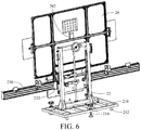
- the second target 220 includes a second target body 222 and a connection post 224; the second target body 222 is mounted at one end of the connection post 224; the second target body 222 has a target surface; the target surface has a center point 2220; the target surface is provided with a pattern for facilitating to determine the position of a target surface of the second target body 222 in a coordinate when the computer 15 processes pattern information of the target surface of the second target body 222; the center point of the pattern is located at the center of the target surface and may be used as the reference point of the second target 220.
- the connection post 224 is used for mounting the calibration device 20.
- connection post 224 is inserted into the fixed base 262; a center line B of the target surface of the second target 222 and the longitudinal center line A of the calibration device 20 are located in a same vertical surface (referring to FIG. 6 ), so that the center point 2200 of the target surface of the second target 220 is located at the central axis surface of the calibration device 20.
- the second image sensor 14 may be omitted, and at least one of the two first image sensors 12 may slide along the bracket 114. After the two first image sensors 12 finish photographing the four first targets 320, the first image sensors 12 that can slide along the bracket 114 slide to the middle of the bracket 114, to photograph the second target 220; or the second image sensor 14 may be omitted, and the two first image sensors 12 are fixedly mounted at two ends of the bracket 114; after the two first image sensors 12 finish photographing the four first targets 320, at least one of the two first image sensors 12 uses the two-axial gimbal or triaxial gimbal to adjust the photographing angle, to photograph the second target 220.
- the second image sensor 14 may be omitted, and the two first image sensors 12 are fixedly mounted at two ends of the bracket 114.
- two ends of the transverse support shaft 230 are separately provided with a fixation device 234; the fixation device 234 is mounted with the second target 220; the two second targets 220 are respectively located at two ends of the transverse support shaft 230; the position of the longitudinal center line A of the calibration device 20 can be determined according to the preset position relation between the two second targets 220 and the longitudinal center line A of the calibration device 20; for example, by presetting a connection line of two reference points of the two second targets 220 to be perpendicular to the longitudinal center line A of the calibration device 20 and the two reference points of the two second targets 220 to respectively have an equal distance from the geometric center point of the transverse support shaft 230, the computer 15 can obtain the position of the longitudinal center line A of the calibration device 20 according to the preset position relation between the two reference points of the second targets 220 and the longitudinal center line A of the calibration device 20.
- the geometric center point of the transverse support shaft 230 and the longitudinal center line A of the calibration device 20 are located at the same vertical
- the wheel aligner 10 When the wheel aligner 10 is used for aligning the calibration device 20 with the vehicle 30, one of the first image sensors 12 is used for photographing two first targets 320 and one second target 220 located at one side of the vehicle 30, the other one of the first image sensors 12 is used for photographing the other two first targets 320 and the other second target 220 located at the other side of the vehicle 30.
- the computer 14 is used for processing the image photographed by the two first image sensors 12, and determining the positions of the four first targets 320 and the positions of the two second targets 220; and the computer 14 obtains the position information of the vehicle 30 based on the positions of the four targets 320 and obtains the position information of the calibration device 20 based on the positions of the two second targets 220.
- the computer 14 is further used for determining the adjusting mode of the calibration device 20 based on the position information of the vehicle 30 and the position information of the calibration device 20, so that the calibration device 20 is aligned with the vehicle 30 according to an anticipated position or direction; or in some alternative embodiments, one of the first image sensors 12 is used for photographing the two first targets 320 located at one side of the vehicle 30, the other one of the first image sensors 12 is used for photographing the other two first targets 320 located at the other side of the vehicle 30.
- the computer 14 is used for processing images photographed by the two first image sensors 12 and determining positions of the four targets 320, so as to obtain position information of the vehicle 30.
- the two first image sensors 12 further respectively photograph the two second targets 220; the computer 14 is used for processing images of the second targets 220 and determining the positions of the second targets 220, so as to obtain the position information of the calibration device 20.
- one end of the transverse support shaft 230 is provided with a fixation device 234; the fixation device 234 is mounted with the second targets 220; the second targets 220 may rotate around a transverse axis C of the transverse support shaft 230, so that the second targets 220 are located at different position states.
- the second target 220 includes a connection post 2200; the center axis of the connection post 2200 overlaps the transverse axis C; one end of the connection post 2200 is threadedly fit with the fixation device 234; and the connection post 2200 may rotate around the transverse axis C with respect to the fixation device 234 so as to drive the second target 220 to rotate around the transverse axis C.
- the operator may adjust the second target 220 so that the second target 220 rotates around the transverse axis C.
- the reference point of the second target 220 is separated from the geometric center point of the transverse support shaft 230 by a preset distance.
- the geometric center point of the transverse support shaft 230 and the longitudinal center line A of the calibration device 20 are located at the same vertical surface.
- one of the first image sensors 12 is used for photographing two first targets 320 and the second target 220 located at one side of the vehicle 30; the second target 220 rotates around the transverse axis C to adjust to different position states; the first image sensors 12 further photograph the second target 220; the other one of the first image sensors 12 is used for photographing the other two first targets 320 at the other side of the vehicle 30.
- the computer 14 is used for processing a first target image obtained by photographing by the two first image sensors 12 and determining the positions of the four first targets 320; and the computer 14 obtains, according to the positions of the four first targets 320, the position information of the vehicle 30.
- the computer 14 is used for determining the position of the second target 220 and the position of the transverse axis C based on second target images at different position states photographed by one of the first image sensors 12, and obtaining the position information of the calibration device 20 by combining the preset distance between the reference point of the second target 220 and the geometric center point of the transverse support shaft 230.
- the computer 14 is further used for determining, an adjusting mode of the calibration device 20 based on the position information of the vehicle 30 and the position information of the calibration device 20, so that the calibration device 20 is aligned with the vehicle 30 according to an anticipated position or direction.
- one of the first image sensors 12 is used for photographing the two first targets 320 located at one side of the vehicle 30, the other one of the first image sensors 12 is used for photographing the other two first targets 320 located at the other side of the vehicle 30.
- the computer 14 is used for processing images photographed by the two first image sensors 12 and determining positions of the four targets 320, so as to obtain position information of the vehicle 30.
- the first image sensors 12 located at one side of the second targets 220 further respectively photograph at least two second targets 220 at different position states; the computer 14 is used for processing the second target images at different position states, determining the positions of the second targets 220, and the position of the transverse axis C, and obtaining, by combining the preset distance between the reference point of the second target 220 and the geometric center point of the transverse support shaft 230, the position information of the calibration device 20.
- the position of the geometric center point of the transverse support shaft 230 can be determined based on the preset distance between the reference point of the second target 220 and the geometric center point of the transverse support shaft 230. Using a straight line passing through the geometric center point and perpendicular to the transverse axis C as the longitudinal center line A of the calibration device 20 may obtain the position of the longitudinal center line A of the calibration device 20.
- the second target 220 may be disposed at any position of the calibration device 20 as long as the second target 220 may rotate around a rotation axis, so that the second target 220 can be adjusted to a different position state; the image sensor images the second target 220; the computer 15 can determine the position of the reference point of the second target 220 and the position of the rotation shaft based on the second target images of different states; the relative positions of the rotation shaft and the transverse axis C may be preset; the computer 15 calculates the position of the transverse axis C according to the preset relative position between the rotation shaft and the transverse axis C.
- first and second are merely for the purpose of description; when the image sensor is used for imaging the first target 320, the image sensor is used as a "first image sensor”; when the image sensor is used for imaging the second target 220, the image sensor is used as a "second image sensor”; for example, in the scene shown in FIG. 9 , the image sensors 12 are used as the first image sensor and the second image sensor at the same time for imaging the first target 320 and the second target 220; for another example, in the scene shown in FIG. 11 , one of the image sensors 12 is first used as the first image sensor for imaging the first target 320 and is then used as the second image sensor for imaging the second target 220.
- the number of the image sensors can be changed according to actual requirements, as long as it is at least one, for example, one image sensor is mounted at the bracket 114; and the image sensor may slide along the bracket 114 to different preset photographing points; when sliding to one side of the vehicle 30, the image sensor may image the two first targets 320 or the second target 220 located at one side of the vehicle 30; when sliding to the middle of the bracket 114, the image sensor may image the second target 220; when sliding to the other side of the vehicle 30, the image sensor may image the other two first targets 320 or the second target 220 located at the other side of the vehicle 30.
- FIG. 13 is a flow chart of a method for aligning a calibration device with a vehicle based on a wheel aligner provided by an embodiment of the present invention.
- the scene of the method is as shown in FIG. 1 , FIG. 9 , and FIG. 11 .
- the method is described below by combining FIG. 1 , FIG. 9 , FIG. 11 , and FIG. 13 .
- the method includes:
- a computer controls at least one image sensor to image a vehicle-mounted object on a vehicle and process the obtained image, to determine a position of the vehicle.
- the vehicle 30 is driven into a track platform 500.
- the track platform 500 may use a track platform in the prior art for adjusting a horizontal height of the vehicle 30, and at the same time, four tires 310 of the vehicle 30 are located at a same horizontal plane.
- a first target 320 is mounted on each of the tires 310.
- the mounting post 324 is mounted on a hub fixture of the tire 310; the positions of the four first targets 320 are adjusted, so that four reference points of the four first targets 320 are respectively distant from a longitudinal center line O of the vehicle 30 by an equal distance; two reference points of two first targets 320 located at front wheels are symmetric with respect to the longitudinal center line O of the vehicle 30, and two reference points of two first targets 320 located at rear wheels are also symmetric with respect to the longitudinal center line O of the vehicle 30, so that the four reference points of the four first targets 320 are respectively located at four vertexes of a rectangle, and the central axis of the rectangle overlaps the longitudinal center line O of the vehicle 30.
- the wheel aligner 10 and the calibration device 20 are moved right in front of (or right behind) the vehicle 30; the calibration device 20 is located between the wheel aligner 10 and the vehicle 30; both the wheel aligner 10 and the calibration device 20 are generally located at the center in front of the vehicle 30 and are approximately perpendicular to a front part of the vehicle 30.
- the target surface of the first target body 322 faces the four-wheel aligner 10.
- the target surface of the second target 220 faces away from the vehicle 30 and faces the wheel aligner 10.
- the wheel aligner 10 and the calibration device 20 are separated by a preset distance, for example, separated by 1.5 m.
- the bracket 114 is horizontally disposed.
- the computer 15 adjusts the angle of the first image sensor 12 located at one side of the vehicle 30, so that the first image sensor 12 is aligned with the target surfaces of two first targets 320 located at one side of the vehicle 30; similarly, the computer 15 adjusts the angle of the other first image sensor 12 located at the other side of the vehicle 30, so that the first image sensor 12 is aligned with the target surfaces of the two first targets 320 located at the other side of the vehicle 30.
- the operator adjusts the height of the wheel aligner 10, so that the two first image sensors 12 and the first targets 320 are generally located at the same horizontal plane.
- the two first image sensors 12 are started; the computer 15 is used for controlling the two first image sensors 12 to respectively photograph the target surfaces of the four first targets 320, and respectively obtaining first image information and second image information.
- the first targets 320 are used as the vehicle-mounted objects, to facilitate the computer 15 to accurately and rapidly determine the position of the first target 320 based on the first target image.
- vehicle-mounted objects for assisting in positioning can also be used.
- the computer 15 processes the first image information and the second image information; for example, the computer 15 uses the SLAM algorithm, to determine the positions of the four reference points of the four first targets 320 in a coordinate system based on the first image information and the second image information.
- An origin point of the coordinate system may be at any position, for example, the position where either one of the two first image sensors 12 is located or the position where the second image sensor 14 is located is used as the origin point of the coordinate system; in the scene shown in FIG. 1 , the computer 15 uses the position of the second image sensor 14 in the coordinate system as the origin point of the coordinate system.
- the computer 15 determines, based on the image of the vehicle-mounted object, the position of the vehicle-mounted object with respect to the first image sensor 12; the computer 15 determines, based on the position of the vehicle-mounted object with respect to the first image sensor 12, the position of the vehicle 30 with respect to the first image sensor 12; the computer 15 determines, based on the position of the vehicle 3 0 with respect to the first image sensor 12 and the position of the first image sensor 12 with respect to the second image sensor 14, the position of the vehicle 30 with respect to the second image sensor 14.
- the position information of the vehicle 30 includes the position information of the longitudinal center line O of the vehicle 30.
- the computer 15 uses the four first targets 320 as vehicle-mounted objects for imaging; each first target 320 has a reference point; the computer 15 determines, based on the images of the vehicle-mounted objects, the positions of the reference points with respect to the first image sensors 12; the computer 15 obtains the position of the longitudinal center line of the four reference points of the four first targets 320 with respect to the first image sensors 12, and uses the position of the longitudinal center line of the four reference points with respect to the first image sensors 12 as the position of the longitudinal center line O of the vehicle 30 with respect to the first image sensors 12.
- the computer 15 determines, based on the position of the longitudinal center line O of the vehicle 30 with respect to the first image sensors 12 and the positions of the first image sensors 12 with respect to the second image sensor 14, the position of the longitudinal center line O of the vehicle 30 with respect to the second image sensor 14.
- the longitudinal center line O of the vehicle 30 is located at a central axis surface of the vehicle 30 and is horizontally disposed.
- the central axis surface of the vehicle 30 is vertically disposed and the vehicle 30 is symmetrically disposed with respect to the central axis surface thereof.
- the position information of the vehicle 30 may further include position information of a point 300 in the middle of the two front tires 310 of the vehicle 30.
- the computer 15 can calculate the position of the point 300 according to the positions of the four reference points of the four first targets 320 in the coordinate system.
- one image sensor is mounted at the bracket 114, and the image sensor may slide along the bracket 114 to different preset photographing points; when sliding to a preset photographing point at one side of the vehicle 30, the image sensor images two first targets 320 located at one side of the vehicle 30 to obtain the first image information; when sliding to a preset photographing point at the other side of the vehicle 30, the image sensor images the other two first targets 320 located at the other side of the vehicle 30 to obtain the second image information.
- the computer controls at least one image sensor to image a reference object on a calibration device and process the obtained image, to determine a position of the calibration device.
- the second target 220 is mounted on the calibration device 20.
- the target surface of the second target 220 faces away from the vehicle 30, faces the four-wheel aligner 10, and is vertically disposed, and the center point 2200 of the target surface of the second target 220 is located at a central axis surface of the calibration device 20.
- the central axis surface of the calibration device 20 is vertically disposed and the calibration device 20 is symmetrically disposed with respect to the central axis surface thereof.
- the second target 220 is used as a reference object.
- the second image sensor 14 is located at the middle position between the two first image sensors 12; and the second image sensor 14 is separately away from the two first image sensors 12 by an equal distance.
- the computer 15 adjusts the angle of the second image sensor 14 so that the second image sensor 14 is aligned with the target surface of the second target 220.
- the operator adjusts the calibration device 20, so that the second image sensor 14 and the second target 220 are generally located at the same horizontal plane.
- the computer 15 determines, based on the image of the reference object, the position of the reference point in the image of the reference object with respect to the second image sensor 14; the computer 15 determines, based on the position correspondence between the position of the reference point in the image of the reference object with respect to the second image sensor 14 and the position of the center of the calibration device 20, the position of the center of the calibration device 20 with respect to the second image sensor 14.
- the second image sensor 14 is started; the computer 15 is used for controlling the second image sensor 14 to photograph the target surface of the second target 220, so as to obtain third image information.
- the computer 15 processes the third image information and determines, based on the third image information, the position of a reference point in the target surface of the second target 220 with respect to the second image sensor 14.
- the position information of the calibration device 20 includes the position information of the longitudinal center line of the calibration device 20.
- the second image sensor 14 uses the second target 220 as a reference object for imaging; the second target 220 has a reference point; the computer 15 calculates the position information of the longitudinal center line A of the calibration device 20 by using the reference point of the second target 220.
- a center point 2200 of the target surface of the second target 220 is used as the reference point and a straight line passing through the center point 2200 of the target surface of the second target 220 and perpendicular to the target surface of the second target 220 is used as the longitudinal center line A of the calibration device 20;
- the computer 15 adopts a SLAM algorithm to calculate, based on the position of the reference point of the target surface of the second target 220 with respect to the second image sensor 14, the position of the longitudinal center line A of the calibration device 20 with respect to the second image sensor 14 (i.e., using the position of the second image sensor 14 as the position of the origin point in the coordinate system).
- the position of the straight line passing through the reference point and perpendicular to the target surface of the second target 220 is calculated by using any point of the target surface of the second target 220 as the reference point; the relative positions of the straight line passing through the reference point and perpendicular to the target surface of the second target 220 and the longitudinal center line A of the calibration device 20 are preset; the computer 15 adopts the SLAM algorithm to calculate the position of the longitudinal center line A of the calibration device 20 in the coordinate system based on the position of the straight line passing through the reference point and perpendicular to the target surface of the second target 220.
- the longitudinal center line A of the calibration device 20 is located at a central axis surface of the calibration device 20 and is horizontally disposed.
- the second image sensor 14 is located at the middle position between the first image sensors 12 and the second image sensor 13, and the second image sensor 14 is separately away from the two first image sensors 12 by an equal distance; the distance between either of the two first image sensors 12 and the second image sensor 14 can be respectively obtained in advance through manual measurement; and when the computer 15 controls the second image sensor 14 to photograph and construct the coordinate system, the computer 15 determines, based on the distance between the first image sensors 12 and the second image sensor 14 obtained in advance, the positions of the two first image sensors 12 in the coordinate system.
- Both the wheel aligner 10 and the calibration device 20 are generally located at the center in front of the vehicle 30 and are generally perpendicular to a front part of the vehicle 30.
- the two first image sensors 12 are generally symmetrical with respect to the longitudinal center line O of the vehicle 30; the first image information of the first targets 320 mounted on the four tires 310 photographed by the two first image sensors 12 is similar to the second image information; and the computer 15 may process the first image information and the second image information more rapidly to reduce a data processing amount.
- the second image sensor 14 may be located at any position between the two first image sensors 12; and when the computer 15 controls the second image sensor 14 to photograph and construct the coordinate system, the computer 15 determines the positions of the two first image sensors 12 in the coordinate system based on the respective distance obtained in advance between the two first image sensors 12 and the second image sensor 14. The computer 15 may calculate the positions of the four reference points of the four first targets 320 in the coordinate system based on the first image information and the second image information of the four first targets 320 respectively photographed by the first image sensor 12.
- the center point 2200 of the target surface of the second target 220 is located at the central axis surface of the calibration device 20; the computer 15 may use the center point 2200 of the target surface of the second target 220 as the reference point, use the straight line passing through the center point 2200 of the target surface of the second target 220 and perpendicular to the target surface of the second target 220 as the longitudinal center line A of the calibration device 20, and directly calculate the position of the longitudinal center line A of the calibration device 20 in the coordinate system based on the position of the target surface of the second target 220 in the coordinate system, so as to reduce the data processing amount.
- the center point 2200 of the target surface of the second target 220 is not limited to being located at the central axis surface of the calibration device 20 and can be disposed at any position of the calibration device 20 according to actual conditions; the distance between the center point 2200 of the target surface of the second target 220 and the central axis surface of the calibration device 20 can be obtained in advance through manual measurement; the computer 15 determines the position of the longitudinal center line A of the calibration device 20 in the coordinate system based on the distance between the center point 2200 and the central axis surface of the calibration device 20 obtained in advance and the position of the center point 2200 of the target surface of the second target 220 in the coordinate system.
- the computer 15 controls one of the first image sensors 12 to photograph the two first targets 320 and the second target 220 located at one side of the vehicle 30, and controls the other one of the first image sensors 12 to photograph the other two first targets 320 and the other second target 220 located at the other side of the vehicle 30.
- the computer 14 processes images photographed by the two first image sensors 12 and determines the positions of the two second targets 220.
- the computer 15 controls the two first image sensors 12 to respectively and individually image the two second targets 220.
- the computer 15 determines the position of the longitudinal center line A of the calibration device 20 based on the preset position relation between the two second targets 220 and the longitudinal center line A of the calibration device 20; for example, by presetting a connection line of two reference points of the two second targets 220 to be perpendicular to the longitudinal center line A of the calibration device 20 and the two reference points of the two second targets 220 to respectively have an equal distance from the geometric center point of the transverse support shaft 230, the computer 15 can obtain the position of the longitudinal center line A of the calibration device 20 based on the preset position relation between the two reference points of the second targets 220 and the longitudinal center line A of the calibration device 20.
- the geometric center point of the transverse support shaft 230 and the longitudinal center line A of the calibration device 20 are located at the same vertical surface.
- the first image sensors 12 located at one side of the second targets 220 image the second targets 220 at different position states and obtain the second target images at different position states; the computer 14 determines the positions of the second targets 220 and the position of the transverse axis C based on the second target images at different position states, and obtains the position information of the calibration device 20 by combining the preset distance between the reference points of the second targets 220 and the geometric center point of the transverse support shaft 230. Specifically, according to the preset distance between the reference point of the second target 220 and the geometric center point of the transverse support shaft 230, the position of the geometric center point of the transverse support shaft 230 can be determined. By using a straight line passing through the geometric center point and perpendicular to the transverse axis C as the longitudinal center line A of the calibration device 20, the position of the longitudinal center line A of the calibration device 20 may be obtained.
- one image sensor is mounted at the bracket 114, and the image sensor may slide along the bracket 114 to different preset photographing points; and when the image sensor slides to one side of the second target 220, the computer 15 controls the image sensor to image the second targets 220 at different position states, to obtain second target images at different position states.
- the second target 220 is used as the reference object, to facilitate the computer 15 to accurately and rapidly determine the position of the second target 220 based on the second target image.
- other reference objects for assisting in positioning can also be used.
- the computer determines an adjusting mode of the calibration device based on the position of the vehicle and the position of the calibration device, so that the calibration device is aligned with the vehicle according to an anticipated position or direction.
- the computer 15 compares the position of the longitudinal center line A of the calibration device 20 with the position of the longitudinal center line O of the vehicle 30 to obtain a deviation value.
- the deviation value includes a transverse distance and an included angle between the longitudinal center line A and the longitudinal center line O.
- the transverse distance and the included angle between the longitudinal center line A and the longitudinal center line O are both zero, i.e., when the longitudinal center line A and the longitudinal center line O overlap, the calibration requirements are achieved.
- the vertical surface of the calibration device 20 refers to a surface of the calibration device 20 facing the vehicle and approximately perpendicular to the ground.
- an angle of the intersection line between the vertical surface of the calibration device 20 and the central axis surface of the vehicle 30 with respect to the ground can be calculated based on the reference point on the second target 220, or an angle of the vertical surface of the calibration device 20 with respect to the ground is calculated based on the reference point on the second target 220, and the position of the central axis surface of the vehicle 30 is calculated based on the reference point on the first target 320, so as to calculate, based on an angle of the vertical surface of the calibration device 20 with respect to the ground and the position of the central axis surface of the vehicle, an angle of the intersection line between the vertical surface of the calibration device 20 and the central axis surface of the vehicle 30 with respect to the ground, and guide the operator to adjust the calibration device 20, so that the intersection line between the vertical surface of the calibration device 20 and the central axis surface of the vehicle 30 is perpendicular to the ground.
- the calibration device 20 is aligned with the vehicle 30; the operator may install the calibration component on the calibration device 20, such as, a radar calibration component, a pattern board, and a reflection mirror, to calibrate the driver assistance system of the vehicle 30, such as a vehicle-mounted radar, a vehicle-mounted camera, and a vehicle-mounted lane keeping system.
- the calibration component such as, a radar calibration component, a pattern board, and a reflection mirror, to calibrate the driver assistance system of the vehicle 30, such as a vehicle-mounted radar, a vehicle-mounted camera, and a vehicle-mounted lane keeping system.
- the computer 15 includes a display 150; the computer 15 may control the display 150 to display the position derivation between the vehicle and the calibration device.
- the computer 15 is installed with graphics processing software, for example, SLAM software, and can simulate a three-dimensional graph of the calibration device 20 and the vehicle 30, and display same in the display 150.
- graphics processing software for example, SLAM software
- the display 150 displays, in the three-dimensional image of the calibration device 20 and the vehicle 30, the longitudinal center line A of the calibration device 20 and the longitudinal center line O of the vehicle 30.
- the display 150 displays, in the three-dimensional image of the calibration device 20 and the vehicle 30, a deviation value of the longitudinal center line A of the calibration device 20 and the longitudinal center line O of the vehicle 30.
- the computer 15 may display, in the three-dimensional image, an error signal indicating a direction and deviation size.
- the operator may move the calibration device 20 with respect to the vehicle 30 according to the indication direction to eliminate the deviation between the vehicle 30 and the calibration device 20.
- the first image sensors 12 and the second image sensor 14 continuously photograph new images, and the computer 15 repeatedly processes and analyzes the updated images and indicates again whether the indication direction is expected or wrong. According to requirements, the calibration device 20 is repeatedly moved until the computer 15 calculates that the deviation between the vehicle 30 and the calibration device 20 is eliminated.
- the display 150 displays, in the three-dimensional image of the calibration device 20 and the vehicle 30, the vertical surface of the calibration device 20, the central axis surface of the vehicle 30, and the intersection line of the vertical surface of the calibration device 20 and the central axis surface of the vehicle 30.
- the computer 15 may display, in the three-dimensional image, the angle value and indication direction of the intersection line and the ground; and the operator may adjust, according to the angle value and the indication direction, an pitch angle of the calibration device 20 until the intersection line is perpendicular to the ground.
- the method further includes: 440.
- the computer calculates a distance between the calibration device and the vehicle along a longitudinal center line of the vehicle, compares the distance between the calibration device and the vehicle and a preset calibration distance, and obtains a longitudinal distance deviation value.
- the computer determines the adjusting direction of the calibration device based on the longitudinal distance deviation value, so that the distance between the calibration device and the vehicle is the preset calibration distance.
- a distance L between the point 300 located between the two front wheels 310 and the center point 2200 of the target surface of the second target 220 may be used as the distance between the calibration device 20 and the vehicle 30 along the longitudinal center line O of the vehicle 30.
- the computer 15 can calculate the position of the point 300 based on the positions of the four reference points of the four first targets 320 in the coordinate system, and can calculate the distance L between the point 300 and the center point 2200 of the target surface of the second target 220 based on the position of the point 300 and the position of the center point 2200 of the target surface of the second target 220.
- the preset calibration distance between the calibration device 20 and the vehicle 30 can be determined according to the standard specification provided by a calibration device manufacturer.
- the computer 15 compares the preset calibration distance and the distance between the calibration device 20 and the vehicle 30, to obtain the longitudinal distance deviation value to guide the operator to move the calibration device 20 along the longitudinal center line O of the vehicle 30.
- step 450 after step 450 is finished, steps 410 to 450 are repeated, so that the calibration device 20 is aligned with the vehicle 30 more accurately.
- the position of the calibration device 20 and the position of the vehicle 30 are determined by using the wheel aligner 10; the computer 15 determines the adjusting mode of the calibration device 20 based on the position of the vehicle 30 and the position of the calibration device 20 and may guide an operator to conveniently and accurately align the calibration device 20 with the vehicle 30 according to an anticipated position or direction.
Landscapes
- Engineering & Computer Science (AREA)
- Physics & Mathematics (AREA)
- General Physics & Mathematics (AREA)
- Computer Vision & Pattern Recognition (AREA)
- Theoretical Computer Science (AREA)
- Multimedia (AREA)
- Signal Processing (AREA)
- Length Measuring Devices By Optical Means (AREA)
Abstract
Description
- The present application claims priority to Chinese Patent Application No.
201811611372.2 - The present application relates to the technical field of automobile calibrations, and in particular, to a method for aligning a calibration device with a vehicle based on a wheel aligner and a calibration system.
- An Advanced Driver Assistance System (ADAS) is an active safety technology of using various sensors mounted on a vehicle to immediately collect environmental data inside and outside the vehicle for technical processing such as identification, detection and tracking of static and dynamic articles, to enable a driver to be aware of possible dangers in the quickest time, to raise attention and improve safety. The sensors adopted by the ADAS mainly include cameras, radars, lasers, and ultrasound, etc., can detect light, heat, pressure, or other variables for monitoring vehicle states, and are generally located on front and rear bumpers, side-view mirrors, the inside of a steering stick, or a windshield of the vehicle.
- During maintenance of the vehicle, calibration equipment is required to be placed right in front of or right behind the vehicle so that the calibration device is aligned with the vehicle, that is, a longitudinal center line of the vehicle is perpendicular to a transverse axis of the calibration device, and the longitudinal center line of the vehicle passes through a geometric center point of the calibration device, or the longitudinal center line of the vehicle overlaps a longitudinal center line of the calibration device. After the calibration device is aligned with the vehicle, the calibration device may install various calibration components, to calibrate sensors such as vehicle-mounted cameras, radars, lasers, or ultrasounds. However, the current alignment between the calibration device and the vehicle lacks assistance equipment, and as a result, the calibration operation is inconvenient and the accuracy is relatively low.
- To resolve the technical problems above, embodiments of the present invention provide a method for aligning a calibration device with a vehicle based on a wheel aligner and a calibration system, so that the calibration device can be conveniently and accurately aligned with the vehicle.
- The embodiments of the present invention provide the following technical solutions to resolve the technical problems.
- A method for aligning a calibration device with a vehicle based on a wheel aligner, where:
- the wheel aligner includes at least one image sensor and a computer communicatively connected to the at least one image sensor;
- the method includes:
- controlling, by the computer, the at least one image sensor to image a vehicle-mounted object on the vehicle and process the obtained image, to determine a position of the vehicle;
- controlling, by the computer, the at least one image sensor to image a reference object on the calibration device and process the obtained image, to determine a position of the calibration device; and
- determining, by the computer, an adjusting mode of the calibration device based on the position of the vehicle and the position of the calibration device, so that the calibration device is aligned with the vehicle according to an anticipated position or direction.
- Optionally, the at least one image sensor includes at least one first image sensors and at least one second image sensor;
the controlling, by the computer, the at least one image sensor to image a vehicle-mounted object on the vehicle and process the obtained image, to determine a position of the vehicle includes: controlling, by the computer, the at least one first image sensor to image the vehicle-mounted object on the vehicle and process the obtained image, to determine the position of the vehicle; and
the controlling, by the computer, the at least one image sensor to image a reference object on the calibration device and process the obtained image, to determine a position of the calibration device includes: controlling, by the computer, the at least one second image sensor to image the reference object on the calibration device and process the obtained image, to determine the position of the calibration device. - Optionally, the wheel aligner includes a bracket; and the at least one first image sensor and the at least one second image sensor are mounted on the bracket.
- Optionally, the at least one first image sensor is disposed at two ends of the bracket, and the at least one second image sensor is disposed in the middle of the bracket; and
the reference object on the calibration device is disposed on the side, departed from the vehicle and facing the bracket, of the calibration device. - Optionally, the controlling, by the computer, the at least one second image sensor to image the reference object on the calibration device and process the obtained image, to determine the position of the calibration device includes:
- determining, by the computer based on an image of the reference object, a position of a reference point in the image of the reference object with respect to the second image sensor; and
- determining, by the computer based on the position of the reference point in the image of the reference object with respect to the second image sensor and a position correspondence between the reference point and a center of the calibration device, a position of a center of the calibration device with respect to the second image sensor.
- Optionally, the controlling, by the computer, the at least one second image sensor to image the reference object on the calibration device and process the obtained image, to determine the position of the calibration device includes:
- controlling, by the computer, the at least one second image sensor to image different position states of the reference object on the calibration device to obtain at least two reference object images; and
- determining a position of a transverse support shaft of the calibration device based on the at least two reference object images, where
- the reference object presents different position states around the transverse support shaft of the calibration device, and the transverse support shaft of the calibration device is used for bearing a calibration component.
- Optionally, the controlling, by the computer, the at least one first image sensor to image the vehicle-mounted object on the vehicle and process the obtained image, to determine the position of the vehicle includes:
- determining, by the computer based on an image of the vehicle-mounted object, a position of the vehicle-mounted object with respect to the first image sensor;
- determining, by the computer based on the position of the vehicle-mounted object with respect to the first image sensor, the position of the vehicle with respect to the first image sensor; and
- determining, by the computer based on the position of the vehicle with respect to the first image sensor and the position of the first image sensor with respect to the second image sensor, the position of the vehicle with respect to the second image sensor.
- Optionally, the wheel aligner includes a bracket, and the at least one image sensor is disposed at two ends of the bracket; and
two ends of the transverse support shaft of the calibration device are respectively provided with two reference objects, and the transverse support shaft of the calibration device is used for bearing the calibration component. - Optionally, the controlling, by the computer, the at least one image sensor to image a reference object on the calibration device and process the obtained image, to determine a position of the calibration device includes:
- determining, by the computer, positions of the reference objects on two ends of the transverse support shaft of the calibration device; and
- determining, by the computer, a position of a center point and/or the transverse support shaft of the calibration device based on the positions of the reference objects on the two ends.
- Optionally, the determining, by the computer, a position of a center point and/or the transverse support shaft of the calibration device based on the positions of the reference objects on the two ends includes:
- determining, by the computer, positions of the two ends of the transverse support shaft of the calibration device based on the positions of the reference objects on the two ends; and
- determining, by the computer, the position of the center point and/or the transverse support shaft of the calibration device based on the positions of the two ends of the transverse support shaft.
- The embodiments of the present invention further adopt the following technical solution to resolve the technical problem.
- A calibration system, including:
- a wheel aligner, including at least one image sensor and a computer communicatively connected to the at least one image sensor; and
- a calibration device, including a reference object; where
- the computer is configured to control the at least one image sensor to image a vehicle-mounted object on a vehicle and process the obtained image, to determine a position of the vehicle;
- the computer is further configured to control the at least one image sensor to image a reference object on the calibration device and process the obtained image, to determine a position of the calibration device; and
- the computer is further configured to determine an adjusting mode of the calibration device based on the position of the vehicle and the position of the calibration device, so that the calibration device is aligned with the vehicle according to an anticipated position or direction.
- Optionally, the wheel aligner includes a bracket;
the at least one image sensor includes at least two first image sensors and at least one second image sensor;
the at least two first image sensor are disposed at two ends of the bracket;
the at least one second image sensor is disposed in the middle of the bracket; and
the reference object on the calibration device is disposed on the side, departed from the vehicle and facing the bracket, of the calibration device. - Optionally, the wheel aligner includes a bracket;
the two image sensors are respectively disposed at two ends of the bracket;
a transverse support shaft of the calibration device is provided with a reference object;
the transverse support shaft of the calibration device is configured to bear a calibration component; and
the reference object presents different position states around the transverse support shaft of the calibration device. - Optionally, the wheel aligner includes a bracket;
the two image sensors are respectively disposed at two ends of the bracket;
two ends of a transverse support shaft of the calibration device are respectively provided with two reference objects, and the transverse support shaft of the calibration device is configured to bear a calibration component. - Optionally, the wheel aligner includes a bracket;
the at least one image sensor is disposed at the bracket and is movable with respect to the bracket; and
the reference object on the calibration device is disposed on the side, departed from the vehicle and facing the bracket, of the calibration device. - Optionally, the wheel aligner includes a bracket;
the at least one image sensor is disposed at the bracket and is movable with respect to the bracket;
a transverse support shaft of the calibration device is provided with a reference object;
the transverse support shaft of the calibration device is configured to bear a calibration component; and
the reference object presents different position states around the transverse support shaft of the calibration device. - Optionally, the wheel aligner includes a bracket;
the at least one image sensor is disposed at the bracket and is movable with respect to the bracket;
two ends of a transverse support shaft of the calibration device are respectively provided with two reference objects, and the transverse support shaft of the calibration device is configured to bear a calibration component. - As compared with the prior art, in the method for aligning a calibration device with a vehicle based on a wheel aligner provided by the embodiments of the present invention, the position of the vehicle and the position of the calibration device are determined by using the wheel aligner, and the computer determines the adjusting mode of the calibration device based on the position of the vehicle and the position of the calibration device and guides an operator to conveniently and accurately align the calibration device with the vehicle according to an anticipated position or direction.
- To describe the technical solutions in the embodiments of the present invention more clearly, the following briefly describes the accompanying drawings required for describing the embodiments of the present invention. Apparently, the accompanying drawings in the following descriptions are merely some embodiments of the present invention, and a person of ordinary skill in the art may further obtain other accompanying drawings according to the accompanying drawings without creative efforts.
-
FIG. 1 is a scene diagram of a method for aligning a calibration device with a vehicle based on a wheel aligner provided by an embodiment of the present invention; -
FIG. 2 is a schematic structural diagram of a wheel aligner provided by an embodiment of the present invention; -
FIG. 3 is a schematic structural diagram of a support assembly of the wheel aligner as shown inFIG. 2 ; -
FIG. 4 is a schematic structural diagram of a calibration device provided by an embodiment of the present invention; -
FIG. 5 is a schematic structural diagram of the calibration device as shown inFIG. 4 , where the calibration device is mounted with a radar calibration board and a pattern board; -
FIG. 6 is a schematic structural diagram of the calibration device as shown inFIG. 5 from another angle; -
FIG. 7 is a schematic structural diagram of a first target provided by an embodiment of the present invention; -
FIG. 8 is a schematic structural diagram of a second target provided by an embodiment of the present invention; -
FIG. 9 is a scene diagram of a method for aligning a calibration device with a vehicle based on a wheel aligner shown in some embodiments of the present invention; -
FIG. 10 is a schematic structural diagram of the calibration device in the scene diagram shown inFIG. 9 ; -
FIG. 11 is a scene diagram of a method for aligning a calibration device with a vehicle based on a wheel aligner shown in other embodiments of the present invention; -
FIG. 12 is a schematic structural diagram of the calibration device in the scene diagram shown inFIG. 11 ; and -
FIG. 13 is a flow chart of a method for aligning a calibration device with a vehicle based on a wheel aligner provided by an embodiment of the present invention. - To make the objectives, technical solutions, and advantages of the present invention clearer and more comprehensible, the following further describes the present invention in detail with reference to the accompanying drawings and embodiments. It should be understood that the embodiments herein are provided for describing the present invention and not intended to limit the present invention.
- In addition, technical features involved in different embodiments of the present invention described below may be combined together if there is no conflict.
-
FIG. 1 is a scene diagram of a method for aligning a calibration device with a vehicle based on a wheel aligner provided by an embodiment of the present invention. - As shown in
FIG. 1 , the scene includes: a calibration system and avehicle 30. The calibration system includes awheel aligner 10 and acalibration device 20. Thecalibration device 20 is placed right in front of thevehicle 30, and thecalibration device 20 is located between thewheel aligner 10 and thevehicle 30. Thewheel aligner 10 is used for aligning thecalibration device 20 with thevehicle 30 so that a calibration component installed on thecalibration device 20 can calibrate vehicle-mounted equipment on thevehicle 30. - The
wheel aligner 10 includes asupport assembly 11,first image sensors 12, asecond image sensor 14, and acomputer 15. Thefirst image sensors 12 and thesecond image sensor 14 are mounted on thesupport assembly 11, and thecomputer 15 may be communicatively connected to thefirst image sensors 12 and thesecond image sensor 14. - Referring to
FIG. 2 andFIG. 3 , thesupport assembly 11 includes acolumn 110, a clampingmember 112, and abracket 114. - The
column 110 may be fixed on the ground with four foundation bolts. Thecolumn 110 may also be supported at another type of base, as long as thecolumn 110 remains stationary and can support thebracket 114. - The clamping
member 112 is mounted at thecolumn 110; the clampingmember 112 may move along thecolumn 110 with respect to thecolumn 110, and the clampingmember 112 may be fixed at a desired horizontal height, for example, the clampingmember 112 is sleeved on thecolumn 110, the clampingmember 112 includes a bolt, the bolt can be abutted against thecolumn 110 so that the clampingmember 112 is fixed at thecolumn 110, and the bolt can be screwed so as to be departed from thecolumn 110, so that the clampingmember 112 may move along thecolumn 110 with respect to thecolumn 110. - The
bracket 114 is mounted at the clampingmember 112; and thebracket 114 is of a columnar structure, and is perpendicular to thecolumn 110. - In this embodiment, the
bracket 114 is mounted at thecolumn 110 through the clampingmember 112. By using the clampingmember 112, thebracket 114 may move with respect to thecolumn 110, so as to facilitate adjusting the horizontal height thereof. As can be understood, in some other embodiments, the clampingmember 112 may be omitted, thebracket 114 is directly mounted at thecolumn 110, and by adjusting the horizontal height of thecolumn 110, the horizontal height of thebracket 114 can be adjusted. - The
first image sensors 12 and thesecond image sensor 14 are all mounted on thebracket 114, where the twofirst image sensors 12 are respectively located at two ends of thebracket 114, and thesecond image sensor 14 is located in the middle of thebracket 114. Thefirst image sensors 12 and thesecond image sensor 14 may be any image sensor of a proper type, such as CCD-based or CMOS-based digital camera. Each of thefirst image sensors 12 and/or thesecond image sensor 14 includes a two-axial or triaxial gimbal, and can receive a control signal to adjust a photographing angle thereof; or each of thefirst image sensors 12 and/or thesecond image sensor 14 is fixedly mounted on the bracket; or each of thefirst image sensors 12 and/or thesecond image sensor 14 may adjust a photographing angle thereof to a specific photographing angle through a mechanic structure matching thebracket 114. - In this embodiment, the middle of the
bracket 114 is any part between two ends of thebracket 114; thesecond image sensor 14 may be located at any position between the twofirst image sensors 12, for example, thesecond image sensor 14 is located between the twofirst image sensors 12, and thesecond image sensor 14 is separately away from the twofirst image sensors 12 by an equal distance. - The
computer 15 may be communicatively connected to thefirst image sensors 12 and thesecond image sensor 14, for example, thecomputer 15 may be wiredly connected to thefirst image sensors 12 and thesecond image sensor 14 through a data line, or thecomputer 15 may be connected in wireless communication to thefirst image sensors 12 and thesecond image sensor 14 in a wireless communication mode such as WiFi and Bluetooth. Thecomputer 15 may be a desktop computer, a laptop computer, a Personal Digital Assistant (PDA), a server, a smart phone, and other electronic devices having a computing function. Thecomputer 15 includes adisplay 150 and an input control device 152 (referring toFIG. 1 ). Theinput control device 152 is used for inputting a user instruction, including a keyboard, a mouse, a touch tablet, and the like. Thecomputer 15 is installed with graphics processing software, for example, SLAM software, for processing image information obtained from thefirst image sensor 12 and thesecond image sensor 14, simulating a three-dimensional graph, and displaying at thedisplay 150 so as to guide an operator to execute a corresponding operation. Alternatively, thecomputer 15 further analyzes the processed image to determine, according to the image, the current position of thecalibration device 20, to compare the current position and an anticipated position of thecalibration device 20 and output an adjustment suggestion according to the comparison result. As can be understood, the image processing software in the embodiment of the present application may be image processing software self-made by a manufacturer for implementing the image processing function above, or may be commercially available image processing software. The embodiment of the present application does not limit the image processing software. - Referring to
FIG. 4 , thecalibration device 20 includes abase bracket 21, acolumn bracket 22, abracket assembly 23, and a slidingmember 24. - One end of the
column bracket 22 is connected to thebase bracket 21, and thebase bracket 21 supports thecolumn bracket 22. - The
bracket assembly 23 is mounted at thecolumn bracket 22, and may move in a vertical direction with respect to thecolumn bracket 22. - The sliding
member 24 is mounted at thebracket assembly 23, and may move in a horizontal direction with respect to thebracket assembly 23. - The
base bracket 21 includes abracket body 210,rollers 212, andheight adjusting members 214. Thebracket body 210 is a rectangular flat panel and may be made of a metal material, and in order to reduce weight, a plurality of hollow regions are formed. Thebracket body 210 has a central axis A which may be used as a longitudinal center line of thecalibration device 20. - The
rollers 212 are mounted at a bottom surface of thebracket body 210 for facilitate moving thebase bracket 21. In this embodiment, therollers 212 are universal moving rollers, so that thebase bracket 21 may arbitrarily move front, back, left, and right; the number of therollers 212 is four, and the rollers are respectively at four corners of thebracket body 210. As can be understood, in some other embodiments, the shape of thebracket body 210 may be changed according to actual requirements, rather than being limited as rectangle; for example, thebracket body 210 may be circular; the number of therollers 212 may be increased or reduced according to actual requirements, as long as it is at least three. - The
height adjusting members 214 are mounted at the bottom surface of thebracket body 210 for adjust the height of thebracket body 210. In this embodiment, theheight adjusting members 214 are adjusting hand wheels, and the number thereof is three. The three adjustinghand wheels 214 are distributed in an isosceles triangle; two adjustinghand wheels 214 located at a bottom edge of the isosceles triangle are disposed at one side of thebracket body 210 and are symmetrically disposed with respect to the central axis A of thebracket body 210, and the other adjustinghand wheel 214 is disposed at the other side of thebracket body 210 and is disposed on the central axis A of the bracket body 210 (i.e., being disposed at the vertex position of a vertex angle of the isosceles triangle). Matching of the three adjustinghand wheels 214 may adjust a horizontal angle of thebracket body 210 as a whole. Separately adjusting the adjustinghand wheel 214 on the central axis A of thebracket body 210 may adjust a pitch angle of thebracket body 210. - As can be understood, the
height adjusting members 214 may be other devices that can adjust the height; the number of theheight adjusting members 214 may be increased according to actual requirements, as long as it is at least three. - The
column bracket 22 is perpendicular to a plane where thebracket body 210 is located. - The
bracket assembly 23 includes atransverse support shaft 230 and a mountingbase 232; thetransverse support shaft 230 is mounted at thecolumn bracket 22 and thetransverse support shaft 230 is horizontally disposed; and the mountingbase 232 is mounted at thetransverse support shaft 230 for mounting a calibration component. - The sliding
member 24 is mounted at thetransverse support shaft 230, and may move in a horizontal direction with respect to thetransverse support shaft 230. In this embodiment, the slidingmember 24 is movably mounted at thetransverse support shaft 230 through a sliding bearing. The slidingmember 24 includes a plurality of installation points for mounting the calibration component. - As can be understood, there are a plurality of modes for installing the calibration component on the
transverse support shaft 230; in addition to slidably mounting the calibration component at thetransverse support shaft 230, it can also be installed on thetransverse support shaft 230 using a mounting member; with this regard, the embodiment of the present application does not limit the installation modes of the calibration component of thetransverse support shaft 230. - Referring to
FIG. 5 andFIG. 6 , aradar calibration board 25 is mounted at the slidingmember 24, to calibrate a vehicle-mounted radar; a mounting post of apattern board 26 is inserted into the mountingbase 232 for calibrating a vehicle-mounted lane keeping system. A back surface of thepattern board 26 is provided with a fixedbase 262 for mounting a target. A center line of thepattern board 26, a center line of the fixedbase 262, a center line of a target surface of the target of the fixedbase 262, and a longitudinal center line A of thecalibration device 20 are located in a same vertical surface. Moving thebracket assembly 23 in a vertical direction with respect to thecolumn bracket 22 may adjust a horizontal height of the target of the fixedbase 262. As can be understood, in some other embodiments, a structure for mounting the target can be disposed at any position of thecalibration device 20 according to actual requirements, as long as the target is departed from thevehicle 30 and faces thebracket 114. For example, a fixation device is disposed at thetransverse support shaft 230 for mounting the target, and the target is departed from thevehicle 30 and faces thebracket 114. - As can be understood, the
calibration device 20 in the embodiment of the present application may include a universal type bracket, a simple bracket, a special bracket, etc. For example, the calibration device is the universal type bracket, and can support the calibration component adapted to a plurality of vehicle types and models such as a radar calibration member and a pattern board. The simple bracket may facilitate movements and can support the calibration components for one or more systems or sensors in an assistance system. The special bracket is merely used for supporting the calibration components of special vehicle types and models. - In the embodiment of the present application, the definitions of the object and the target are consistent.
- Referring to
FIG. 1 again, in the scene, thecalibration device 20 is placed between thewheel aligner 10 and thevehicle 30. Before calibration of vehicle-mounted equipment of thevehicle 30 such as a camera and a radar using the calibration component installed on thecalibration device 20, it is required to use thewheel aligner 10 to locate the calibratedevice 20 right in front of or right behind thevehicle 30, or other positions indicated in a calibration manual with respect to the vehicle. - In this case, four
first targets 320 are respectively mounted on fourtires 310 of thevehicle 30, and thefirst targets 320 may be understood as vehicle-mounted objects. In an implementation, eachfirst target 320 has a reference point; four reference points of the fourfirst targets 320 are respectively distant from a longitudinal center line O of thevehicle 30 by an equal distance; two reference points of twofirst targets 320 located at front wheels are symmetric with respect to the longitudinal center line O of thevehicle 30, and two reference points of twofirst targets 320 located at rear wheels are also symmetric with respect to the longitudinal center line O of thevehicle 30, so that the four reference points of the fourfirst targets 320 are respectively located at four vertexes of a rectangle, and the central axis of the rectangle overlaps the longitudinal center line O of thevehicle 30. Certainly, in the embodiment of the present application, eachfirst target 320 may further include a plurality of reference points, which are not limited herein. - A
second target 220 is mounted on thecalibration device 20, and the second target may be understood as a reference object. - One of the
first image sensors 12 is used for photographing twofirst targets 320 at one side of thevehicle 30, the other one of thefirst image sensors 12 is used for photographing the other twofirst targets 320 located at the other side of thevehicle 30. Thecomputer 14 is used for processing images photographed by the twofirst image sensors 12 and determining positions of the fourtargets 320, so as to obtain position information of thevehicle 30. Specifically, the position information of thevehicle 30 may include the positions of the reference points of thevehicle 30, for example, calculating the position of each wheel center; and furthermore, an overall position of the vehicle is determined according to the positions of the reference points, for example, the position of the central axis or thrust line in the vehicle; or the position information of thevehicle 30 may include the position of the central axis or thrust line in the vehicle; the position of the central axis or thrust line in the vehicle can be calculated directly based on the positions of the reference points on thefirst targets 320. Thesecond image sensor 14 is used for photographing thesecond target 220; thecomputer 14 is used for processing an image obtained by photographing by thesecond image sensor 14 and determining the position of thesecond target 220, so as to obtain the position information of thecalibration device 20. Specifically, the position information of thecalibration device 20 may include the center position of thecalibration device 20, the position of a certain shaft of thecalibration device 20, etc., or position information for assisting in determining the position of the calibration component on the calibration device. Thecomputer 15 is further used for determining, an adjusting mode of thecalibration device 20 based on the position information of thevehicle 30 and the position information of thecalibration device 20, so that thecalibration device 20 is aligned with thevehicle 30 according to an anticipated position or direction. - In this embodiment, the position information of the
vehicle 30 includes position information of the longitudinal center line O of thevehicle 30. Thecomputer 15 images the fourfirst targets 320 as vehicle-mounted objects; thecomputer 15 obtains the position of the central axis of the four reference points of the fourfirst targets 320, and uses the position of the central axis of the four reference points as the position of the longitudinal center line O of thevehicle 30. In this embodiment, the longitudinal center line O of thevehicle 30 is located at a central axis surface of thevehicle 30 and is horizontally disposed. The central axis surface of thevehicle 30 is vertically disposed and thevehicle 30 is symmetrically disposed with respect to the central axis surface thereof. - In some embodiments, the position information of the
vehicle 30 may further include position information of apoint 300 in the middle of the twofront tires 310 of thevehicle 30. - In this embodiment, the position information of the
calibration device 20 includes the position information of the longitudinal center line of thecalibration device 20. Thesecond image sensor 14 images thesecond target 220 as a reference object; thesecond target 220 has a reference point; and thecomputer 15 calculates the position information of the longitudinal center line A of thecalibration device 20 using the reference point of thesecond target 220. For example, acenter point 2200 of the target surface of thesecond target 220 is used as the reference point and a straight line passing through thecenter point 2200 of the target surface of thesecond target 220 and perpendicular to the target surface of thesecond target 220 is used as the longitudinal center line A of thecalibration device 20; thecomputer 15 adopts a SLAM algorithm to calculate the position of the longitudinal center line A of thecalibration device 20 in a coordinate system according to the position of the target surface of thesecond target 220 in the coordinate system; for another example, any point of the target surface of thesecond target 220 is used as the reference point; the position of the straight line passing through the reference point and perpendicular to the target surface of thesecond target 220 is calculated; the relative positions of the straight line passing through the reference point and perpendicular to the target surface of thesecond target 220 and the longitudinal center line A of thecalibration device 20 are preset; thecomputer 15 adopts the SLAM algorithm to calculate the position of the longitudinal center line A of thecalibration device 20 in the coordinate system according to the position of the straight line passing through the reference point and perpendicular to the target surface of thesecond target 220. - The longitudinal center line A of the
calibration device 20 is located at a central axis surface of thecalibration device 20 and is horizontally disposed. - In this embodiment, the transverse distance between the longitudinal center line A and the longitudinal center line O is zero, i.e., when the longitudinal center line A overlaps the longitudinal center line O, the calibration requirement is met, and the
calibration device 20 is aligned with thevehicle 30. - Furthermore, in some embodiments, while requiring to overlap the longitudinal center line A of the
calibration device 20 with the longitudinal center line O of the vehicle, it further requires to correct a vertical surface of thecalibration device 20, i.e., adjusting an intersection line between the vertical surface of thecalibration device 20 and the central axis surface of thevehicle 30 to be perpendicular to the ground, so that the requirements of position adjustment of thecalibration device 20 can be achieved. The vertical surface of thecalibration device 20 refers to a surface of thecalibration device 20 facing the vehicle and approximately perpendicular to the ground. Specifically, an angle of the intersection line between the vertical surface of thecalibration device 20 and the central axis surface of thevehicle 30 with respect to the ground can be calculated based on the reference point on thesecond target 220, or an angle of the vertical surface of thecalibration device 20 with respect to the ground is calculated based on the reference point on thesecond target 220, and the position of the central axis surface of thevehicle 30 is calculated based on the reference point on thefirst target 320, so as to calculate, based on an angle of the vertical surface of thecalibration device 20 with respect to the ground and the position of the central axis surface of the vehicle, an angle of the intersection line between the vertical surface of thecalibration device 20 and the central axis surface of thevehicle 30 with respect to the ground, and guide the operator to adjust thecalibration device 20, so that the intersection line between the vertical surface of thecalibration device 20 and the central axis surface of thevehicle 30 is perpendicular to the ground. - After the
calibration device 20 is aligned with thevehicle 30, thecalibration device 20 can install, according to actual requirements, the calibration component, such as a radar calibration component, a pattern board, and a reflection mirror, to calibrate the driver assistance system of thevehicle 30. - In this embodiment, the
computer 15 is installed with graphics processing software, for example, SLAM software, which can simulate a three-dimensional image of thecalibration device 20 and thevehicle 30 and display same in thedisplay 150. According to a first calibration target image and a second calibration target image, thecomputer 15 controls thedisplay 150 to display the longitudinal center line A of thecalibration device 20 and the longitudinal center line O of thevehicle 30 in the three-dimensional image of thecalibration device 20 and thevehicle 30. Meanwhile, thedisplay 150 displays a deviation value of the longitudinal center line O of thevehicle 30 and the longitudinal center line A of thecalibration device 20 in the three-dimensional image of thecalibration device 20 and thevehicle 30. To facilitate guiding the operator to align thecalibration device 20 with thevehicle 30, thecomputer 15 may display, in the three-dimensional image, an error signal indicating a direction and deviation size. The operator may move thecalibration device 20 with respect to thevehicle 30 according to the indication direction to reduce or eliminate the deviation between thevehicle 30 and thecalibration device 20. In the process of moving thecalibration device 20 with respect to thevehicle 30, thefirst image sensors 12 and thesecond image sensor 14 continuously photograph new images, and thecomputer 15 repeatedly processes and analyzes the updated images and indicates again whether the indication direction is expected or wrong. According to requirements, thecalibration device 20 is repeatedly moved until thecomputer 15 calculates that the deviation between thevehicle 30 and thecalibration device 20 is eliminated. - Referring to
FIG. 7 , eachfirst target 320 includes afirst target body 322 and a mountingpost 324; thefirst target body 322 is mounted at one end of the mountingpost 324; thefirst target body 322 has a target surface; the target surface has a pattern for facilitating determining the position of a target surface of thefirst target body 322 in a coordinate when thecomputer 15 processes pattern information of the target surface of thefirst target body 322; the center point of the pattern may be used as the reference point of thefirst target 320. The mountingpost 324 is used for mounting thetire 310. - Referring to
FIG. 8 , thesecond target 220 includes asecond target body 222 and aconnection post 224; thesecond target body 222 is mounted at one end of theconnection post 224; thesecond target body 222 has a target surface; the target surface has acenter point 2220; the target surface is provided with a pattern for facilitating to determine the position of a target surface of thesecond target body 222 in a coordinate when thecomputer 15 processes pattern information of the target surface of thesecond target body 222; the center point of the pattern is located at the center of the target surface and may be used as the reference point of thesecond target 220. Theconnection post 224 is used for mounting thecalibration device 20. Specifically, theconnection post 224 is inserted into the fixedbase 262; a center line B of the target surface of thesecond target 222 and the longitudinal center line A of thecalibration device 20 are located in a same vertical surface (referring toFIG. 6 ), so that thecenter point 2200 of the target surface of thesecond target 220 is located at the central axis surface of thecalibration device 20. - As can be understood, in some embodiments, the
second image sensor 14 may be omitted, and at least one of the twofirst image sensors 12 may slide along thebracket 114. After the twofirst image sensors 12 finish photographing the fourfirst targets 320, thefirst image sensors 12 that can slide along thebracket 114 slide to the middle of thebracket 114, to photograph thesecond target 220; or thesecond image sensor 14 may be omitted, and the twofirst image sensors 12 are fixedly mounted at two ends of thebracket 114; after the twofirst image sensors 12 finish photographing the fourfirst targets 320, at least one of the twofirst image sensors 12 uses the two-axial gimbal or triaxial gimbal to adjust the photographing angle, to photograph thesecond target 220. - As can be understood, in some embodiments, referring to
FIG. 9 , thesecond image sensor 14 may be omitted, and the twofirst image sensors 12 are fixedly mounted at two ends of thebracket 114. - Referring to
FIG. 10 , two ends of thetransverse support shaft 230 are separately provided with afixation device 234; thefixation device 234 is mounted with thesecond target 220; the twosecond targets 220 are respectively located at two ends of thetransverse support shaft 230; the position of the longitudinal center line A of thecalibration device 20 can be determined according to the preset position relation between the twosecond targets 220 and the longitudinal center line A of thecalibration device 20; for example, by presetting a connection line of two reference points of the twosecond targets 220 to be perpendicular to the longitudinal center line A of thecalibration device 20 and the two reference points of the twosecond targets 220 to respectively have an equal distance from the geometric center point of thetransverse support shaft 230, thecomputer 15 can obtain the position of the longitudinal center line A of thecalibration device 20 according to the preset position relation between the two reference points of thesecond targets 220 and the longitudinal center line A of thecalibration device 20. The geometric center point of thetransverse support shaft 230 and the longitudinal center line A of thecalibration device 20 are located at the same vertical surface. - When the
wheel aligner 10 is used for aligning thecalibration device 20 with thevehicle 30, one of thefirst image sensors 12 is used for photographing twofirst targets 320 and onesecond target 220 located at one side of thevehicle 30, the other one of thefirst image sensors 12 is used for photographing the other twofirst targets 320 and the othersecond target 220 located at the other side of thevehicle 30. - The
computer 14 is used for processing the image photographed by the twofirst image sensors 12, and determining the positions of the fourfirst targets 320 and the positions of the twosecond targets 220; and thecomputer 14 obtains the position information of thevehicle 30 based on the positions of the fourtargets 320 and obtains the position information of thecalibration device 20 based on the positions of the twosecond targets 220. Thecomputer 14 is further used for determining the adjusting mode of thecalibration device 20 based on the position information of thevehicle 30 and the position information of thecalibration device 20, so that thecalibration device 20 is aligned with thevehicle 30 according to an anticipated position or direction; or in some alternative embodiments, one of thefirst image sensors 12 is used for photographing the twofirst targets 320 located at one side of thevehicle 30, the other one of thefirst image sensors 12 is used for photographing the other twofirst targets 320 located at the other side of thevehicle 30. Thecomputer 14 is used for processing images photographed by the twofirst image sensors 12 and determining positions of the fourtargets 320, so as to obtain position information of thevehicle 30. The twofirst image sensors 12 further respectively photograph the twosecond targets 220; thecomputer 14 is used for processing images of thesecond targets 220 and determining the positions of thesecond targets 220, so as to obtain the position information of thecalibration device 20. - Referring to
FIG. 11 andFIG. 12 , in some embodiments, one end of thetransverse support shaft 230 is provided with afixation device 234; thefixation device 234 is mounted with thesecond targets 220; thesecond targets 220 may rotate around a transverse axis C of thetransverse support shaft 230, so that thesecond targets 220 are located at different position states. Specifically, thesecond target 220 includes aconnection post 2200; the center axis of theconnection post 2200 overlaps the transverse axis C; one end of theconnection post 2200 is threadedly fit with thefixation device 234; and theconnection post 2200 may rotate around the transverse axis C with respect to thefixation device 234 so as to drive thesecond target 220 to rotate around the transverse axis C. The operator may adjust thesecond target 220 so that thesecond target 220 rotates around the transverse axis C. - Along the direction parallel to the transverse axis C, the reference point of the
second target 220 is separated from the geometric center point of thetransverse support shaft 230 by a preset distance. The geometric center point of thetransverse support shaft 230 and the longitudinal center line A of thecalibration device 20 are located at the same vertical surface. - When the
wheel aligner 10 is used for aligning thecalibration device 20 with thevehicle 30, one of thefirst image sensors 12 is used for photographing twofirst targets 320 and thesecond target 220 located at one side of thevehicle 30; thesecond target 220 rotates around the transverse axis C to adjust to different position states; thefirst image sensors 12 further photograph thesecond target 220; the other one of thefirst image sensors 12 is used for photographing the other twofirst targets 320 at the other side of thevehicle 30. - The
computer 14 is used for processing a first target image obtained by photographing by the twofirst image sensors 12 and determining the positions of the fourfirst targets 320; and thecomputer 14 obtains, according to the positions of the fourfirst targets 320, the position information of thevehicle 30. - The
computer 14 is used for determining the position of thesecond target 220 and the position of the transverse axis C based on second target images at different position states photographed by one of thefirst image sensors 12, and obtaining the position information of thecalibration device 20 by combining the preset distance between the reference point of thesecond target 220 and the geometric center point of thetransverse support shaft 230. - The
computer 14 is further used for determining, an adjusting mode of thecalibration device 20 based on the position information of thevehicle 30 and the position information of thecalibration device 20, so that thecalibration device 20 is aligned with thevehicle 30 according to an anticipated position or direction. - Alternatively, in some alternative embodiments, one of the
first image sensors 12 is used for photographing the twofirst targets 320 located at one side of thevehicle 30, the other one of thefirst image sensors 12 is used for photographing the other twofirst targets 320 located at the other side of thevehicle 30. Thecomputer 14 is used for processing images photographed by the twofirst image sensors 12 and determining positions of the fourtargets 320, so as to obtain position information of thevehicle 30. Thefirst image sensors 12 located at one side of thesecond targets 220 further respectively photograph at least twosecond targets 220 at different position states; thecomputer 14 is used for processing the second target images at different position states, determining the positions of thesecond targets 220, and the position of the transverse axis C, and obtaining, by combining the preset distance between the reference point of thesecond target 220 and the geometric center point of thetransverse support shaft 230, the position information of thecalibration device 20. - In this embodiment, the position of the geometric center point of the
transverse support shaft 230 can be determined based on the preset distance between the reference point of thesecond target 220 and the geometric center point of thetransverse support shaft 230. Using a straight line passing through the geometric center point and perpendicular to the transverse axis C as the longitudinal center line A of thecalibration device 20 may obtain the position of the longitudinal center line A of thecalibration device 20. - As can be understood, in some other embodiments, the
second target 220 may be disposed at any position of thecalibration device 20 as long as thesecond target 220 may rotate around a rotation axis, so that thesecond target 220 can be adjusted to a different position state; the image sensor images thesecond target 220; thecomputer 15 can determine the position of the reference point of thesecond target 220 and the position of the rotation shaft based on the second target images of different states; the relative positions of the rotation shaft and the transverse axis C may be preset; thecomputer 15 calculates the position of the transverse axis C according to the preset relative position between the rotation shaft and the transverse axis C. - In this embodiment, the terms "first" and "second" are merely for the purpose of description; when the image sensor is used for imaging the
first target 320, the image sensor is used as a "first image sensor"; when the image sensor is used for imaging thesecond target 220, the image sensor is used as a "second image sensor"; for example, in the scene shown inFIG. 9 , theimage sensors 12 are used as the first image sensor and the second image sensor at the same time for imaging thefirst target 320 and thesecond target 220; for another example, in the scene shown inFIG. 11 , one of theimage sensors 12 is first used as the first image sensor for imaging thefirst target 320 and is then used as the second image sensor for imaging thesecond target 220. - As can be understood, in some embodiments, the number of the image sensors can be changed according to actual requirements, as long as it is at least one, for example, one image sensor is mounted at the
bracket 114; and the image sensor may slide along thebracket 114 to different preset photographing points; when sliding to one side of thevehicle 30, the image sensor may image the twofirst targets 320 or thesecond target 220 located at one side of thevehicle 30; when sliding to the middle of thebracket 114, the image sensor may image thesecond target 220; when sliding to the other side of thevehicle 30, the image sensor may image the other twofirst targets 320 or thesecond target 220 located at the other side of thevehicle 30. -
FIG. 13 is a flow chart of a method for aligning a calibration device with a vehicle based on a wheel aligner provided by an embodiment of the present invention. The scene of the method is as shown inFIG. 1 ,FIG. 9 , andFIG. 11 . The method is described below by combiningFIG. 1 ,FIG. 9 ,FIG. 11 , andFIG. 13 . The method includes: - 410. A computer controls at least one image sensor to image a vehicle-mounted object on a vehicle and process the obtained image, to determine a position of the vehicle.
- In the scene shown in
FIG. 1 ,FIG. 9 , orFIG. 11 , when thecalibration device 20 is required to be aligned with thevehicle 30, thevehicle 30 is driven into atrack platform 500. Thetrack platform 500 may use a track platform in the prior art for adjusting a horizontal height of thevehicle 30, and at the same time, fourtires 310 of thevehicle 30 are located at a same horizontal plane. Afirst target 320 is mounted on each of thetires 310. Specifically, the mountingpost 324 is mounted on a hub fixture of thetire 310; the positions of the fourfirst targets 320 are adjusted, so that four reference points of the fourfirst targets 320 are respectively distant from a longitudinal center line O of thevehicle 30 by an equal distance; two reference points of twofirst targets 320 located at front wheels are symmetric with respect to the longitudinal center line O of thevehicle 30, and two reference points of twofirst targets 320 located at rear wheels are also symmetric with respect to the longitudinal center line O of thevehicle 30, so that the four reference points of the fourfirst targets 320 are respectively located at four vertexes of a rectangle, and the central axis of the rectangle overlaps the longitudinal center line O of thevehicle 30. - The
wheel aligner 10 and thecalibration device 20 are moved right in front of (or right behind) thevehicle 30; thecalibration device 20 is located between thewheel aligner 10 and thevehicle 30; both thewheel aligner 10 and thecalibration device 20 are generally located at the center in front of thevehicle 30 and are approximately perpendicular to a front part of thevehicle 30. The target surface of thefirst target body 322 faces the four-wheel aligner 10. - The target surface of the
second target 220 faces away from thevehicle 30 and faces thewheel aligner 10. - The
wheel aligner 10 and thecalibration device 20 are separated by a preset distance, for example, separated by 1.5 m. Thebracket 114 is horizontally disposed. Thecomputer 15 adjusts the angle of thefirst image sensor 12 located at one side of thevehicle 30, so that thefirst image sensor 12 is aligned with the target surfaces of twofirst targets 320 located at one side of thevehicle 30; similarly, thecomputer 15 adjusts the angle of the otherfirst image sensor 12 located at the other side of thevehicle 30, so that thefirst image sensor 12 is aligned with the target surfaces of the twofirst targets 320 located at the other side of thevehicle 30. The operator adjusts the height of thewheel aligner 10, so that the twofirst image sensors 12 and thefirst targets 320 are generally located at the same horizontal plane. - The two
first image sensors 12 are started; thecomputer 15 is used for controlling the twofirst image sensors 12 to respectively photograph the target surfaces of the fourfirst targets 320, and respectively obtaining first image information and second image information. - In this embodiment, the
first targets 320 are used as the vehicle-mounted objects, to facilitate thecomputer 15 to accurately and rapidly determine the position of thefirst target 320 based on the first target image. As can be understood, in some other embodiments, other vehicle-mounted objects for assisting in positioning can also be used. - The
computer 15 processes the first image information and the second image information; for example, thecomputer 15 uses the SLAM algorithm, to determine the positions of the four reference points of the fourfirst targets 320 in a coordinate system based on the first image information and the second image information. An origin point of the coordinate system may be at any position, for example, the position where either one of the twofirst image sensors 12 is located or the position where thesecond image sensor 14 is located is used as the origin point of the coordinate system; in the scene shown inFIG. 1 , thecomputer 15 uses the position of thesecond image sensor 14 in the coordinate system as the origin point of the coordinate system. - The
computer 15 determines, based on the image of the vehicle-mounted object, the position of the vehicle-mounted object with respect to thefirst image sensor 12; thecomputer 15 determines, based on the position of the vehicle-mounted object with respect to thefirst image sensor 12, the position of thevehicle 30 with respect to thefirst image sensor 12; thecomputer 15 determines, based on the position of the vehicle 3 0 with respect to thefirst image sensor 12 and the position of thefirst image sensor 12 with respect to thesecond image sensor 14, the position of thevehicle 30 with respect to thesecond image sensor 14. - Specifically, the position information of the
vehicle 30 includes the position information of the longitudinal center line O of thevehicle 30. Thecomputer 15 uses the fourfirst targets 320 as vehicle-mounted objects for imaging; eachfirst target 320 has a reference point; thecomputer 15 determines, based on the images of the vehicle-mounted objects, the positions of the reference points with respect to thefirst image sensors 12; thecomputer 15 obtains the position of the longitudinal center line of the four reference points of the fourfirst targets 320 with respect to thefirst image sensors 12, and uses the position of the longitudinal center line of the four reference points with respect to thefirst image sensors 12 as the position of the longitudinal center line O of thevehicle 30 with respect to thefirst image sensors 12. When using the position of thesecond image sensor 14 in the coordinate system as the origin point of the coordinate system, thecomputer 15 determines, based on the position of the longitudinal center line O of thevehicle 30 with respect to thefirst image sensors 12 and the positions of thefirst image sensors 12 with respect to thesecond image sensor 14, the position of the longitudinal center line O of thevehicle 30 with respect to thesecond image sensor 14. - In this embodiment, the longitudinal center line O of the
vehicle 30 is located at a central axis surface of thevehicle 30 and is horizontally disposed. The central axis surface of thevehicle 30 is vertically disposed and thevehicle 30 is symmetrically disposed with respect to the central axis surface thereof. - The position information of the
vehicle 30 may further include position information of apoint 300 in the middle of the twofront tires 310 of thevehicle 30. Thecomputer 15 can calculate the position of thepoint 300 according to the positions of the four reference points of the fourfirst targets 320 in the coordinate system. - As can be understood, in some embodiments, one image sensor is mounted at the
bracket 114, and the image sensor may slide along thebracket 114 to different preset photographing points; when sliding to a preset photographing point at one side of thevehicle 30, the image sensor images twofirst targets 320 located at one side of thevehicle 30 to obtain the first image information; when sliding to a preset photographing point at the other side of thevehicle 30, the image sensor images the other twofirst targets 320 located at the other side of thevehicle 30 to obtain the second image information. - 420. The computer controls at least one image sensor to image a reference object on a calibration device and process the obtained image, to determine a position of the calibration device.
- In the scene shown in
FIG. 1 , thesecond target 220 is mounted on thecalibration device 20. The target surface of thesecond target 220 faces away from thevehicle 30, faces the four-wheel aligner 10, and is vertically disposed, and thecenter point 2200 of the target surface of thesecond target 220 is located at a central axis surface of thecalibration device 20. The central axis surface of thecalibration device 20 is vertically disposed and thecalibration device 20 is symmetrically disposed with respect to the central axis surface thereof. In this embodiment, thesecond target 220 is used as a reference object. - The
second image sensor 14 is located at the middle position between the twofirst image sensors 12; and thesecond image sensor 14 is separately away from the twofirst image sensors 12 by an equal distance. Thecomputer 15 adjusts the angle of thesecond image sensor 14 so that thesecond image sensor 14 is aligned with the target surface of thesecond target 220. The operator adjusts thecalibration device 20, so that thesecond image sensor 14 and thesecond target 220 are generally located at the same horizontal plane. - The
computer 15 determines, based on the image of the reference object, the position of the reference point in the image of the reference object with respect to thesecond image sensor 14; thecomputer 15 determines, based on the position correspondence between the position of the reference point in the image of the reference object with respect to thesecond image sensor 14 and the position of the center of thecalibration device 20, the position of the center of thecalibration device 20 with respect to thesecond image sensor 14. - Specifically, the
second image sensor 14 is started; thecomputer 15 is used for controlling thesecond image sensor 14 to photograph the target surface of thesecond target 220, so as to obtain third image information. - The
computer 15 processes the third image information and determines, based on the third image information, the position of a reference point in the target surface of thesecond target 220 with respect to thesecond image sensor 14. - The position information of the
calibration device 20 includes the position information of the longitudinal center line of thecalibration device 20. Thesecond image sensor 14 uses thesecond target 220 as a reference object for imaging; thesecond target 220 has a reference point; thecomputer 15 calculates the position information of the longitudinal center line A of thecalibration device 20 by using the reference point of thesecond target 220. For example, acenter point 2200 of the target surface of thesecond target 220 is used as the reference point and a straight line passing through thecenter point 2200 of the target surface of thesecond target 220 and perpendicular to the target surface of thesecond target 220 is used as the longitudinal center line A of thecalibration device 20; thecomputer 15 adopts a SLAM algorithm to calculate, based on the position of the reference point of the target surface of thesecond target 220 with respect to thesecond image sensor 14, the position of the longitudinal center line A of thecalibration device 20 with respect to the second image sensor 14 (i.e., using the position of thesecond image sensor 14 as the position of the origin point in the coordinate system). For another example, the position of the straight line passing through the reference point and perpendicular to the target surface of thesecond target 220 is calculated by using any point of the target surface of thesecond target 220 as the reference point; the relative positions of the straight line passing through the reference point and perpendicular to the target surface of thesecond target 220 and the longitudinal center line A of thecalibration device 20 are preset; thecomputer 15 adopts the SLAM algorithm to calculate the position of the longitudinal center line A of thecalibration device 20 in the coordinate system based on the position of the straight line passing through the reference point and perpendicular to the target surface of thesecond target 220. - The longitudinal center line A of the
calibration device 20 is located at a central axis surface of thecalibration device 20 and is horizontally disposed. - In this embodiment, the
second image sensor 14 is located at the middle position between thefirst image sensors 12 and the second image sensor 13, and thesecond image sensor 14 is separately away from the twofirst image sensors 12 by an equal distance; the distance between either of the twofirst image sensors 12 and thesecond image sensor 14 can be respectively obtained in advance through manual measurement; and when thecomputer 15 controls thesecond image sensor 14 to photograph and construct the coordinate system, thecomputer 15 determines, based on the distance between thefirst image sensors 12 and thesecond image sensor 14 obtained in advance, the positions of the twofirst image sensors 12 in the coordinate system. Both thewheel aligner 10 and thecalibration device 20 are generally located at the center in front of thevehicle 30 and are generally perpendicular to a front part of thevehicle 30. The twofirst image sensors 12 are generally symmetrical with respect to the longitudinal center line O of thevehicle 30; the first image information of thefirst targets 320 mounted on the fourtires 310 photographed by the twofirst image sensors 12 is similar to the second image information; and thecomputer 15 may process the first image information and the second image information more rapidly to reduce a data processing amount. - As can be understood, in some other implementations, the
second image sensor 14 may be located at any position between the twofirst image sensors 12; and when thecomputer 15 controls thesecond image sensor 14 to photograph and construct the coordinate system, thecomputer 15 determines the positions of the twofirst image sensors 12 in the coordinate system based on the respective distance obtained in advance between the twofirst image sensors 12 and thesecond image sensor 14. Thecomputer 15 may calculate the positions of the four reference points of the fourfirst targets 320 in the coordinate system based on the first image information and the second image information of the fourfirst targets 320 respectively photographed by thefirst image sensor 12. - The
center point 2200 of the target surface of thesecond target 220 is located at the central axis surface of thecalibration device 20; thecomputer 15 may use thecenter point 2200 of the target surface of thesecond target 220 as the reference point, use the straight line passing through thecenter point 2200 of the target surface of thesecond target 220 and perpendicular to the target surface of thesecond target 220 as the longitudinal center line A of thecalibration device 20, and directly calculate the position of the longitudinal center line A of thecalibration device 20 in the coordinate system based on the position of the target surface of thesecond target 220 in the coordinate system, so as to reduce the data processing amount. As can be understood that, in some other embodiments, thecenter point 2200 of the target surface of thesecond target 220 is not limited to being located at the central axis surface of thecalibration device 20 and can be disposed at any position of thecalibration device 20 according to actual conditions; the distance between thecenter point 2200 of the target surface of thesecond target 220 and the central axis surface of thecalibration device 20 can be obtained in advance through manual measurement; thecomputer 15 determines the position of the longitudinal center line A of thecalibration device 20 in the coordinate system based on the distance between thecenter point 2200 and the central axis surface of thecalibration device 20 obtained in advance and the position of thecenter point 2200 of the target surface of thesecond target 220 in the coordinate system. - In the scene shown in
FIG. 9 , thecomputer 15 controls one of thefirst image sensors 12 to photograph the twofirst targets 320 and thesecond target 220 located at one side of thevehicle 30, and controls the other one of thefirst image sensors 12 to photograph the other twofirst targets 320 and the othersecond target 220 located at the other side of thevehicle 30. Thecomputer 14 processes images photographed by the twofirst image sensors 12 and determines the positions of the twosecond targets 220. Alternatively, in some alternative embodiments, thecomputer 15 controls the twofirst image sensors 12 to respectively and individually image the twosecond targets 220. - The
computer 15 determines the position of the longitudinal center line A of thecalibration device 20 based on the preset position relation between the twosecond targets 220 and the longitudinal center line A of thecalibration device 20; for example, by presetting a connection line of two reference points of the twosecond targets 220 to be perpendicular to the longitudinal center line A of thecalibration device 20 and the two reference points of the twosecond targets 220 to respectively have an equal distance from the geometric center point of thetransverse support shaft 230, thecomputer 15 can obtain the position of the longitudinal center line A of thecalibration device 20 based on the preset position relation between the two reference points of thesecond targets 220 and the longitudinal center line A of thecalibration device 20. The geometric center point of thetransverse support shaft 230 and the longitudinal center line A of thecalibration device 20 are located at the same vertical surface. - In the scene shown in
FIG. 11 , thefirst image sensors 12 located at one side of thesecond targets 220 image thesecond targets 220 at different position states and obtain the second target images at different position states; thecomputer 14 determines the positions of thesecond targets 220 and the position of the transverse axis C based on the second target images at different position states, and obtains the position information of thecalibration device 20 by combining the preset distance between the reference points of thesecond targets 220 and the geometric center point of thetransverse support shaft 230. Specifically, according to the preset distance between the reference point of thesecond target 220 and the geometric center point of thetransverse support shaft 230, the position of the geometric center point of thetransverse support shaft 230 can be determined. By using a straight line passing through the geometric center point and perpendicular to the transverse axis C as the longitudinal center line A of thecalibration device 20, the position of the longitudinal center line A of thecalibration device 20 may be obtained. - As can be understood, in some embodiments, one image sensor is mounted at the
bracket 114, and the image sensor may slide along thebracket 114 to different preset photographing points; and when the image sensor slides to one side of thesecond target 220, thecomputer 15 controls the image sensor to image thesecond targets 220 at different position states, to obtain second target images at different position states. - In this embodiment, the
second target 220 is used as the reference object, to facilitate thecomputer 15 to accurately and rapidly determine the position of thesecond target 220 based on the second target image. As can be understood, in some other embodiments, other reference objects for assisting in positioning can also be used. - 430. The computer determines an adjusting mode of the calibration device based on the position of the vehicle and the position of the calibration device, so that the calibration device is aligned with the vehicle according to an anticipated position or direction.
- The
computer 15 compares the position of the longitudinal center line A of thecalibration device 20 with the position of the longitudinal center line O of thevehicle 30 to obtain a deviation value. The deviation value includes a transverse distance and an included angle between the longitudinal center line A and the longitudinal center line O. The transverse distance and the included angle between the longitudinal center line A and the longitudinal center line O are both zero, i.e., when the longitudinal center line A and the longitudinal center line O overlap, the calibration requirements are achieved. - Furthermore, in some embodiments, while requiring to overlap the longitudinal center line A of the
calibration device 20 with the longitudinal center line O of the vehicle, it further requires to correct a vertical surface of thecalibration device 20, i.e., adjusting an intersection line between the vertical surface of thecalibration device 20 and the central axis surface of thevehicle 30 to be perpendicular to the ground, so that the requirements of position adjustment of thecalibration device 20 can be achieved. The vertical surface of thecalibration device 20 refers to a surface of thecalibration device 20 facing the vehicle and approximately perpendicular to the ground. Specifically, an angle of the intersection line between the vertical surface of thecalibration device 20 and the central axis surface of thevehicle 30 with respect to the ground can be calculated based on the reference point on thesecond target 220, or an angle of the vertical surface of thecalibration device 20 with respect to the ground is calculated based on the reference point on thesecond target 220, and the position of the central axis surface of thevehicle 30 is calculated based on the reference point on thefirst target 320, so as to calculate, based on an angle of the vertical surface of thecalibration device 20 with respect to the ground and the position of the central axis surface of the vehicle, an angle of the intersection line between the vertical surface of thecalibration device 20 and the central axis surface of thevehicle 30 with respect to the ground, and guide the operator to adjust thecalibration device 20, so that the intersection line between the vertical surface of thecalibration device 20 and the central axis surface of thevehicle 30 is perpendicular to the ground. - In this case, the
calibration device 20 is aligned with thevehicle 30; the operator may install the calibration component on thecalibration device 20, such as, a radar calibration component, a pattern board, and a reflection mirror, to calibrate the driver assistance system of thevehicle 30, such as a vehicle-mounted radar, a vehicle-mounted camera, and a vehicle-mounted lane keeping system. - To facilitate guiding the operator to align the
calibration device 20 with thevehicle 30, thecomputer 15 includes adisplay 150; thecomputer 15 may control thedisplay 150 to display the position derivation between the vehicle and the calibration device. - The
computer 15 is installed with graphics processing software, for example, SLAM software, and can simulate a three-dimensional graph of thecalibration device 20 and thevehicle 30, and display same in thedisplay 150. According to a first target image and a second target image, thedisplay 150 displays, in the three-dimensional image of thecalibration device 20 and thevehicle 30, the longitudinal center line A of thecalibration device 20 and the longitudinal center line O of thevehicle 30. Meanwhile, thedisplay 150 displays, in the three-dimensional image of thecalibration device 20 and thevehicle 30, a deviation value of the longitudinal center line A of thecalibration device 20 and the longitudinal center line O of thevehicle 30. - To facilitate guiding the operator to align the
calibration device 20 with thevehicle 30, thecomputer 15 may display, in the three-dimensional image, an error signal indicating a direction and deviation size. The operator may move thecalibration device 20 with respect to thevehicle 30 according to the indication direction to eliminate the deviation between thevehicle 30 and thecalibration device 20. In the process of moving thecalibration device 20 with respect to thevehicle 30, thefirst image sensors 12 and thesecond image sensor 14 continuously photograph new images, and thecomputer 15 repeatedly processes and analyzes the updated images and indicates again whether the indication direction is expected or wrong. According to requirements, thecalibration device 20 is repeatedly moved until thecomputer 15 calculates that the deviation between thevehicle 30 and thecalibration device 20 is eliminated. - Furthermore, in some embodiments, the
display 150 displays, in the three-dimensional image of thecalibration device 20 and thevehicle 30, the vertical surface of thecalibration device 20, the central axis surface of thevehicle 30, and the intersection line of the vertical surface of thecalibration device 20 and the central axis surface of thevehicle 30. To facilitate the operator to adjust the intersection line of the vertical surface of thecalibration device 20 and the central axis surface of thevehicle 30 to be perpendicular to the ground, thecomputer 15 may display, in the three-dimensional image, the angle value and indication direction of the intersection line and the ground; and the operator may adjust, according to the angle value and the indication direction, an pitch angle of thecalibration device 20 until the intersection line is perpendicular to the ground. - After the
calibration device 20 is aligned with thevehicle 30, the longitudinal center line O of thevehicle 30 and the longitudinal center line A of thecalibration device 20 overlap; in some conditions, it is further required to calibrate the distance between thecalibration device 20 and thevehicle 30, for example, thecalibration device 20 is a radar calibration device; the radar calibration device requires to calibrate the vehicle-mounted radar of thevehicle 30 only by separating same from thevehicle 30 by a preset calibration distance. Hence, in some other embodiments, the method further includes:
440. The computer calculates a distance between the calibration device and the vehicle along a longitudinal center line of the vehicle, compares the distance between the calibration device and the vehicle and a preset calibration distance, and obtains a longitudinal distance deviation value. - 450. The computer determines the adjusting direction of the calibration device based on the longitudinal distance deviation value, so that the distance between the calibration device and the vehicle is the preset calibration distance.
- In the scene shown in
FIG. 1 , a distance L between thepoint 300 located between the twofront wheels 310 and thecenter point 2200 of the target surface of thesecond target 220 may be used as the distance between thecalibration device 20 and thevehicle 30 along the longitudinal center line O of thevehicle 30. Thecomputer 15 can calculate the position of thepoint 300 based on the positions of the four reference points of the fourfirst targets 320 in the coordinate system, and can calculate the distance L between thepoint 300 and thecenter point 2200 of the target surface of thesecond target 220 based on the position of thepoint 300 and the position of thecenter point 2200 of the target surface of thesecond target 220. The preset calibration distance between thecalibration device 20 and thevehicle 30 can be determined according to the standard specification provided by a calibration device manufacturer. Thecomputer 15 compares the preset calibration distance and the distance between thecalibration device 20 and thevehicle 30, to obtain the longitudinal distance deviation value to guide the operator to move thecalibration device 20 along the longitudinal center line O of thevehicle 30. - As can be understood, in some embodiments, after
step 450 is finished,steps 410 to 450 are repeated, so that thecalibration device 20 is aligned with thevehicle 30 more accurately. - As compared with the prior art, in the method for aligning a calibration device with a vehicle based on a wheel aligner provided by this embodiment, the position of the
calibration device 20 and the position of thevehicle 30 are determined by using thewheel aligner 10; thecomputer 15 determines the adjusting mode of thecalibration device 20 based on the position of thevehicle 30 and the position of thecalibration device 20 and may guide an operator to conveniently and accurately align thecalibration device 20 with thevehicle 30 according to an anticipated position or direction. - Finally, it should be noted that the foregoing embodiments are merely used to describe the technical solutions of the present invention, but are not intended to limit the present invention. Under the concept of the present invention, the technical features in the foregoing embodiments or different embodiments may be combined, the steps may be implemented in any sequence, and there may be many other changes in different aspects of the present invention. For brevity, those are not provided in detail. Although the present invention is described in detail with reference to the foregoing embodiments, a person of ordinary skill in the art should understand that they may still make modifications to the technical solutions described in the foregoing embodiments or make equivalent replacements to some technical features thereof, without departing from the scope of the technical solutions of the embodiments of the present invention.
Claims (17)
- A method for aligning a calibration device with a vehicle based on a wheel aligner, wherein:the wheel aligner comprises at least one image sensor and a computer communicatively connected to the at least one image sensor;the method comprises:controlling, by the computer, the at least one image sensor to image a vehicle-mounted object on the vehicle and process the obtained image, to determine a position of the vehicle;controlling, by the computer, the at least one image sensor to image a reference object on the calibration device and process the obtained image, to determine a position of the calibration device; anddetermining, by the computer, an adjusting mode of the calibration device based on the position of the vehicle and the position of the calibration device, so that the calibration device is aligned with the vehicle according to an anticipated position or direction.
- The method according to claim 1, wherein the at least one image sensor comprises at least one first image sensor and at least one second image sensor;
the controlling, by the computer, the at least one image sensor to image a vehicle-mounted object on the vehicle and process the obtained image, to determine a position of the vehicle comprises: controlling, by the computer, the at least one first image sensor to image the vehicle-mounted object on the vehicle and process the obtained image, to determine the position of the vehicle; and
the controlling, by the computer, the at least one image sensor to image a reference object on the calibration device and process the obtained image, to determine a position of the calibration device comprises: controlling, by the computer, the at least one second image sensor to image the reference object on the calibration device and process the obtained image, to determine the position of the calibration device. - The method according to claim 2, wherein the wheel aligner comprises a bracket; and the at least one first image sensor and the at least one second image sensor are mounted on the bracket.
- The method according to claim 3, wherein
the at least one first image sensor is disposed at two ends of the bracket, and the at least one second image sensor is disposed at middle of the bracket; and
the reference object on the calibration device is disposed on the side, departed from the vehicle and facing the bracket, of the calibration device. - The method according to claim 4, wherein the controlling, by the computer, the at least one second image sensor to image the reference object on the calibration device and process the obtained image, to determine the position of the calibration device comprises:determining, by the computer based on an image of the reference object, a position of a reference point in the image of the reference object with respect to the second image sensor; anddetermining, by the computer based on the position of the reference point in the image of the reference object with respect to the second image sensor and a position correspondence between the reference point and a center of the calibration device, a position of a center of the calibration device with respect to the second image sensor.
- The method according to claim 4 or 5, wherein the controlling, by the computer, the at least one second image sensor to image the reference object on the calibration device and process the obtained image, to determine the position of the calibration device comprises:controlling, by the computer, the at least one second image sensor to image different position states of the reference object on the calibration device to obtain at least two reference object images; anddetermining a position of a transverse support shaft of the calibration device based on the at least two reference object images, whereinthe reference object presents different position states around the transverse support shaft of the calibration device, and the transverse support shaft of the calibration device is used for bearing a calibration component.
- The method according to claim 5 or 6, wherein the controlling, by the computer, the at least one first image sensor to image the vehicle-mounted object on the vehicle and process the obtained image, to determine the position of the vehicle comprises:determining, by the computer based on an image of the vehicle-mounted object, a position of the vehicle-mounted object with respect to the first image sensor;determining, by the computer based on the position of the vehicle-mounted object with respect to the first image sensor, the position of the vehicle with respect to the first image sensor; anddetermining, by the computer based on the position of the vehicle with respect to the first image sensor and the position of the first image sensor with respect to the second image sensor, the position of the vehicle with respect to the second image sensor.
- The method according to claim 1, wherein the wheel aligner comprises a bracket, and the at least one image sensor is disposed at two ends of the bracket; and
two ends of the transverse support shaft of the calibration device are respectively provided with two reference objects, and the transverse support shaft of the calibration device is used for bearing the calibration component. - The method according to claim 8, wherein the controlling, by the computer, the at least one image sensor to image a reference object on the calibration device and process the obtained image, to determine a position of the calibration device comprises:determining, by the computer, positions of the reference objects on two ends of the transverse support shaft of the calibration device; anddetermining, by the computer, a position of a center point and/or the transverse support shaft of the calibration device based on the positions of the reference objects on the two ends.
- The method according to claim 9, wherein the determining, by the computer, a position of a center point and/or the transverse support shaft of the calibration device based on the positions of the reference objects on the two ends comprises:determining, by the computer, positions of the two ends of the transverse support shaft of the calibration device based on the positions of the reference objects on the two ends; anddetermining, by the computer, the position of the center point and/or the transverse support shaft of the calibration device based on the positions of the two ends of the transverse support shaft.
- A calibration system, comprising:a wheel aligner, comprising at least one image sensor and a computer communicatively connected to the at least one image sensor; anda calibration device, comprising a reference object; whereinthe computer is configured to control the at least one image sensor to image a vehicle-mounted object on a vehicle and process the obtained image, to determine a position of the vehicle;the computer is further configured to control the at least one image sensor to image a reference object on the calibration device and process the obtained image, to determine a position of the calibration device; andthe computer is further configured to determine an adjusting mode of the calibration device based on the position of the vehicle and the position of the calibration device, so that the calibration device is aligned with the vehicle according to an anticipated position or direction.
- The calibration system according to claim 11, wherein the wheel aligner comprises a bracket;
the at least one image sensor comprises at least two first image sensors and at least one second image sensor;
the at least two first image sensor are disposed at two ends of the bracket;
the at least one second image sensor is disposed in the middle of the bracket; and
the reference object on the calibration device is disposed on the side, departed from the vehicle and facing the bracket, of the calibration device. - The calibration system according to claim 11, wherein the wheel aligner comprises a bracket;
the two image sensors are respectively disposed at two ends of the bracket;
a transverse support shaft of the calibration device is provided with a reference object;
the transverse support shaft of the calibration device is configured to bear a calibration component; and
the reference object presents different position states around the transverse support shaft of the calibration device. - The calibration system according to claim 11, wherein the wheel aligner comprises a bracket;
the two image sensors are respectively disposed at two ends of the bracket;
two ends of a transverse support shaft of the calibration device are respectively provided with two reference objects, and the transverse support shaft of the calibration device is configured to bear a calibration component. - The calibration system according to claim 11, wherein the wheel aligner comprises a bracket;
the at least one image sensor is disposed at the bracket and is movable with respect to the bracket; and
the reference object on the calibration device is disposed on the side, departed from the vehicle and facing the bracket, of the calibration device. - The calibration system according to claim 11, wherein the wheel aligner comprises a bracket;
the at least one image sensor is disposed at the bracket and is movable with respect to the bracket;
a transverse support shaft of the calibration device is provided with a reference object; the transverse support shaft of the calibration device is configured to bear a calibration component; and
the reference object presents different position states around the transverse support shaft of the calibration device. - The calibration system according to claim 11, wherein the wheel aligner comprises a bracket;
the at least one image sensor is disposed at the bracket and is movable with respect to the bracket; and
two ends of a transverse support shaft of the calibration device are respectively provided with two reference objects, and the transverse support shaft of the calibration device is configured to bear a calibration component.
Applications Claiming Priority (2)
| Application Number | Priority Date | Filing Date | Title |
|---|---|---|---|
| CN201811611372.2A CN111380703B (en) | 2018-12-27 | 2018-12-27 | Method for aligning calibration device to vehicle based on wheel aligner and calibration system |
| PCT/CN2019/128648 WO2020135572A1 (en) | 2018-12-27 | 2019-12-26 | Wheel aligner-based method for aligning calibration device with vehicle and calibration system |
Publications (3)
| Publication Number | Publication Date |
|---|---|
| EP3859298A1 true EP3859298A1 (en) | 2021-08-04 |
| EP3859298A4 EP3859298A4 (en) | 2021-11-24 |
| EP3859298B1 EP3859298B1 (en) | 2024-04-10 |
Family
ID=71128799
Family Applications (1)
| Application Number | Title | Priority Date | Filing Date |
|---|---|---|---|
| EP19902819.2A Active EP3859298B1 (en) | 2018-12-27 | 2019-12-26 | Wheel aligner-based method for aligning calibration device with vehicle and calibration system |
Country Status (4)
| Country | Link |
|---|---|
| US (1) | US12259233B2 (en) |
| EP (1) | EP3859298B1 (en) |
| CN (1) | CN111380703B (en) |
| WO (1) | WO2020135572A1 (en) |
Cited By (1)
| Publication number | Priority date | Publication date | Assignee | Title |
|---|---|---|---|---|
| WO2025190994A1 (en) * | 2024-03-14 | 2025-09-18 | Beissbarth Automotive Testing Solutions Gmbh | Device and method for aligning calibration mats on a vehicle |
Families Citing this family (24)
| Publication number | Priority date | Publication date | Assignee | Title |
|---|---|---|---|---|
| US12573091B2 (en) * | 2018-06-21 | 2026-03-10 | Mahle Aftermarket Italy S.P.A. | System and method of calibrating an optical sensor mounted on board of a vehicle using a graduated mounting bar |
| IT202000004834A1 (en) * | 2020-03-06 | 2021-09-06 | Nexion Spa | METHOD OF ALIGNING A SERVICE SYSTEM WITH A VEHICLE RELATIVE TO A VEHICLE |
| WO2022038544A1 (en) * | 2020-08-18 | 2022-02-24 | BPG Sales and Technology Investments, LLC | Vehicular floor target alignment for sensor calibration |
| CN112033696A (en) * | 2020-09-03 | 2020-12-04 | 深圳市道通科技股份有限公司 | Calibration equipment and calibration method |
| CN112255627B (en) * | 2020-09-25 | 2024-06-04 | 深圳市道通科技股份有限公司 | Positioning method, system, device and readable storage medium for ADAS calibration equipment |
| DE102020213976A1 (en) * | 2020-11-06 | 2022-05-12 | Robert Bosch Gesellschaft mit beschränkter Haftung | Method and system for determining the attitude of a vehicle in preparation for sensor calibration |
| USD1042173S1 (en) * | 2020-12-31 | 2024-09-17 | Autel Intelligent Technology Corp., Ltd. | Wheel aligning and ADAS calibrating apparatus |
| WO2022152463A1 (en) * | 2021-01-14 | 2022-07-21 | Sew-Eurodrive Gmbh & Co. Kg | Method for calibrating a laser scanner, and technical apparatus |
| CN112964274A (en) * | 2021-02-04 | 2021-06-15 | 深圳市米勒沙容达汽车科技有限公司 | Calibration method for vehicle and ADAS sensor target and movable base |
| CN112964273B (en) * | 2021-02-04 | 2024-05-14 | 深圳市米勒沙容达汽车科技有限公司 | ADAS calibration device and full-automatic centering system for vehicle |
| CN113357956B (en) * | 2021-05-31 | 2022-05-20 | 无锡市星迪仪器有限公司 | Artillery zero position detector with fast self-calibration function and self-calibration method |
| US12403917B2 (en) * | 2021-11-29 | 2025-09-02 | Bosch Automotive Service Solutions, Inc. | Calibration apparatus for offset vehicle sensor |
| CN114264272B (en) * | 2022-01-19 | 2024-01-16 | 深圳市道通科技股份有限公司 | Calibration support and calibration system |
| CN114526922B (en) * | 2022-01-21 | 2023-07-07 | 烟台开发区海德科技有限公司 | ADAS (automatic adaptive analysis and for systems) calibration system and calibration method for commercial vehicle |
| CN114739301A (en) * | 2022-04-07 | 2022-07-12 | 深圳市道通科技股份有限公司 | Vehicle body height measuring method |
| CN114720152B (en) * | 2022-04-18 | 2023-08-04 | 烟台大学 | Four-wheel alignment and ADAS integrated detection and calibration system and method |
| CN114993266B (en) * | 2022-06-14 | 2024-03-22 | 深圳市道通科技股份有限公司 | Positioning device and positioning system |
| CN115183673B (en) * | 2022-07-07 | 2024-06-21 | 湖南联智科技股份有限公司 | A method for detecting the structural dimensions of box girder ends |
| CN114963992B (en) * | 2022-07-07 | 2025-06-24 | 湖南联智科技股份有限公司 | A device for detecting the structural dimensions of box beam ends |
| CN115420358A (en) * | 2022-08-16 | 2022-12-02 | 福建省计量科学研究院(福建省眼镜质量检验站) | A Nonphysical Dynamic Calibration System of Dynamic Truck Scale |
| CN117541592B (en) * | 2024-01-10 | 2024-06-21 | 宁德时代新能源科技股份有限公司 | Method for determining camera mounting deviation and visual detection compensation method |
| CN118706171A (en) * | 2024-07-29 | 2024-09-27 | 深圳市道通科技股份有限公司 | Method, device, equipment and storage medium for assisting in placing calibration tools |
| CN118687610A (en) * | 2024-07-29 | 2024-09-24 | 深圳市道通科技股份有限公司 | Method, device, equipment and storage medium for assisting in placing calibration tools |
| EP4707851A1 (en) * | 2024-09-06 | 2026-03-11 | Hella Gutmann Solutions GmbH | Arrangement and method for calibrating at least one radar sensor of a vehicle |
Family Cites Families (9)
| Publication number | Priority date | Publication date | Assignee | Title |
|---|---|---|---|---|
| US6823601B2 (en) * | 2002-09-17 | 2004-11-30 | Snap-On Incorporated | Apparatus for use with a 3D image wheel aligner for facilitating adjustment of an adaptive cruise control sensor on a motor vehicle |
| US7382913B2 (en) * | 2003-08-22 | 2008-06-03 | Hunter Engineering Company | Method and apparatus for guiding placement of vehicle service fixtures |
| CN101040298A (en) * | 2004-10-13 | 2007-09-19 | 罗伯特·博世有限公司 | Device for calibrating an image sensor system in a motor vehicle |
| US7424387B1 (en) * | 2007-04-18 | 2008-09-09 | Snap-On Incorporated | Method for use with an optical aligner system for positioning a fixture relative to a vehicle |
| US7640673B2 (en) * | 2007-08-01 | 2010-01-05 | Snap-On Incorporated | Calibration and operation of wheel alignment systems |
| DE102010062696A1 (en) * | 2010-12-09 | 2012-06-14 | Robert Bosch Gmbh | Method and device for calibrating and adjusting a vehicle environment sensor. |
| IT1404235B1 (en) * | 2010-12-30 | 2013-11-15 | Space S R L Con Unico Socio | DETECTION DEVICE, AND RELATIVE SYSTEM FOR DETERMINING THE WHEEL ORIENTATION OF A VEHICLE |
| EP3628996B1 (en) * | 2018-09-28 | 2022-08-24 | NEXION S.p.A. | Vehicle headlight measurement system instrumentation structure |
| EP3742192B1 (en) * | 2018-09-28 | 2023-09-06 | NEXION S.p.A. | System for calibrating a vehicle camera |
-
2018
- 2018-12-27 CN CN201811611372.2A patent/CN111380703B/en active Active
-
2019
- 2019-12-26 EP EP19902819.2A patent/EP3859298B1/en active Active
- 2019-12-26 WO PCT/CN2019/128648 patent/WO2020135572A1/en not_active Ceased
-
2021
- 2021-05-27 US US17/331,882 patent/US12259233B2/en active Active
Cited By (1)
| Publication number | Priority date | Publication date | Assignee | Title |
|---|---|---|---|---|
| WO2025190994A1 (en) * | 2024-03-14 | 2025-09-18 | Beissbarth Automotive Testing Solutions Gmbh | Device and method for aligning calibration mats on a vehicle |
Also Published As
| Publication number | Publication date |
|---|---|
| US20210285760A1 (en) | 2021-09-16 |
| CN111380703B (en) | 2025-04-18 |
| EP3859298B1 (en) | 2024-04-10 |
| US12259233B2 (en) | 2025-03-25 |
| EP3859298A4 (en) | 2021-11-24 |
| CN111380703A (en) | 2020-07-07 |
| WO2020135572A1 (en) | 2020-07-02 |
Similar Documents
| Publication | Publication Date | Title |
|---|---|---|
| US12259233B2 (en) | Method for aligning calibration device with vehicle based on wheel aligner and calibration system | |
| US11420643B2 (en) | Device and method for calibrating vehicle assistance systems | |
| US11624608B2 (en) | Vehicular alignment for sensor calibration | |
| US11836947B2 (en) | System for calibrating a vehicle camera | |
| US20250180349A1 (en) | System and Method For Identification of Spatial Locations For Vehicle ADAS Calibration | |
| US12385766B2 (en) | Vehicular alignment for sensor calibration | |
| EP3608687B1 (en) | Vehicle advanced assisted driving calibration device | |
| CN111413111A (en) | Method for aligning calibration device to vehicle based on wheel aligner | |
| KR20230051576A (en) | Vehicle Floor Target Alignment for Sensor Calibration | |
| EP3614168B1 (en) | Advanced driver assistance calibration device for vehicle | |
| US10242451B2 (en) | On-vehicle camera calibration auxiliary device | |
| CN112964273A (en) | ADAS calibration device and full-automatic vehicle centering system | |
| WO2026026648A1 (en) | Calibration pattern placement method and calibration apparatus | |
| CN121213673A (en) | Methods for calculating target pattern size, vehicle calibration methods, and electronic equipment. | |
| CN121141190A (en) | Calculation methods for target calibration height, vehicle calibration methods, and electronic equipment. | |
| CN119269117A (en) | Vehicle calibration system, method, electronic device and computer readable storage medium | |
| HK40108447A (en) | Vehicular alignment for sensor calibration |
Legal Events
| Date | Code | Title | Description |
|---|---|---|---|
| STAA | Information on the status of an ep patent application or granted ep patent |
Free format text: STATUS: THE INTERNATIONAL PUBLICATION HAS BEEN MADE |
|
| PUAI | Public reference made under article 153(3) epc to a published international application that has entered the european phase |
Free format text: ORIGINAL CODE: 0009012 |
|
| STAA | Information on the status of an ep patent application or granted ep patent |
Free format text: STATUS: REQUEST FOR EXAMINATION WAS MADE |
|
| 17P | Request for examination filed |
Effective date: 20210430 |
|
| AK | Designated contracting states |
Kind code of ref document: A1 Designated state(s): AL AT BE BG CH CY CZ DE DK EE ES FI FR GB GR HR HU IE IS IT LI LT LU LV MC MK MT NL NO PL PT RO RS SE SI SK SM TR |
|
| A4 | Supplementary search report drawn up and despatched |
Effective date: 20211022 |
|
| RIC1 | Information provided on ipc code assigned before grant |
Ipc: G01B 11/275 20060101ALN20211018BHEP Ipc: G01S 7/40 20060101ALI20211018BHEP Ipc: G06T 7/80 20170101ALI20211018BHEP Ipc: G01M 17/013 20060101ALI20211018BHEP Ipc: G01B 11/27 20060101AFI20211018BHEP |
|
| DAV | Request for validation of the european patent (deleted) | ||
| DAX | Request for extension of the european patent (deleted) | ||
| REG | Reference to a national code |
Ref country code: DE Ref legal event code: R079 Free format text: PREVIOUS MAIN CLASS: G01M0017013000 Ref country code: DE Ref legal event code: R079 Ref document number: 602019050258 Country of ref document: DE Free format text: PREVIOUS MAIN CLASS: G01M0017013000 Ipc: G01B0011270000 |
|
| GRAP | Despatch of communication of intention to grant a patent |
Free format text: ORIGINAL CODE: EPIDOSNIGR1 |
|
| STAA | Information on the status of an ep patent application or granted ep patent |
Free format text: STATUS: GRANT OF PATENT IS INTENDED |
|
| RIC1 | Information provided on ipc code assigned before grant |
Ipc: G01S 13/931 20200101ALN20231110BHEP Ipc: G01B 11/275 20060101ALN20231110BHEP Ipc: G06T 7/73 20170101ALI20231110BHEP Ipc: G01S 7/40 20060101ALI20231110BHEP Ipc: G06T 7/80 20170101ALI20231110BHEP Ipc: G01M 17/013 20060101ALI20231110BHEP Ipc: G01B 11/27 20060101AFI20231110BHEP |
|
| INTG | Intention to grant announced |
Effective date: 20231129 |
|
| GRAS | Grant fee paid |
Free format text: ORIGINAL CODE: EPIDOSNIGR3 |
|
| GRAA | (expected) grant |
Free format text: ORIGINAL CODE: 0009210 |
|
| STAA | Information on the status of an ep patent application or granted ep patent |
Free format text: STATUS: THE PATENT HAS BEEN GRANTED |
|
| AK | Designated contracting states |
Kind code of ref document: B1 Designated state(s): AL AT BE BG CH CY CZ DE DK EE ES FI FR GB GR HR HU IE IS IT LI LT LU LV MC MK MT NL NO PL PT RO RS SE SI SK SM TR |
|
| REG | Reference to a national code |
Ref country code: GB Ref legal event code: FG4D |
|
| REG | Reference to a national code |
Ref country code: CH Ref legal event code: EP |
|
| REG | Reference to a national code |
Ref country code: DE Ref legal event code: R096 Ref document number: 602019050258 Country of ref document: DE |
|
| REG | Reference to a national code |
Ref country code: IE Ref legal event code: FG4D |
|
| REG | Reference to a national code |
Ref country code: LT Ref legal event code: MG9D |
|
| REG | Reference to a national code |
Ref country code: NL Ref legal event code: MP Effective date: 20240410 |
|
| REG | Reference to a national code |
Ref country code: AT Ref legal event code: MK05 Ref document number: 1675313 Country of ref document: AT Kind code of ref document: T Effective date: 20240410 |
|
| PG25 | Lapsed in a contracting state [announced via postgrant information from national office to epo] |
Ref country code: NL Free format text: LAPSE BECAUSE OF FAILURE TO SUBMIT A TRANSLATION OF THE DESCRIPTION OR TO PAY THE FEE WITHIN THE PRESCRIBED TIME-LIMIT Effective date: 20240410 |
|
| PG25 | Lapsed in a contracting state [announced via postgrant information from national office to epo] |
Ref country code: NL Free format text: LAPSE BECAUSE OF FAILURE TO SUBMIT A TRANSLATION OF THE DESCRIPTION OR TO PAY THE FEE WITHIN THE PRESCRIBED TIME-LIMIT Effective date: 20240410 |
|
| PG25 | Lapsed in a contracting state [announced via postgrant information from national office to epo] |
Ref country code: IS Free format text: LAPSE BECAUSE OF FAILURE TO SUBMIT A TRANSLATION OF THE DESCRIPTION OR TO PAY THE FEE WITHIN THE PRESCRIBED TIME-LIMIT Effective date: 20240810 |
|
| PG25 | Lapsed in a contracting state [announced via postgrant information from national office to epo] |
Ref country code: BG Free format text: LAPSE BECAUSE OF FAILURE TO SUBMIT A TRANSLATION OF THE DESCRIPTION OR TO PAY THE FEE WITHIN THE PRESCRIBED TIME-LIMIT Effective date: 20240410 |
|
| PG25 | Lapsed in a contracting state [announced via postgrant information from national office to epo] |
Ref country code: HR Free format text: LAPSE BECAUSE OF FAILURE TO SUBMIT A TRANSLATION OF THE DESCRIPTION OR TO PAY THE FEE WITHIN THE PRESCRIBED TIME-LIMIT Effective date: 20240410 Ref country code: FI Free format text: LAPSE BECAUSE OF FAILURE TO SUBMIT A TRANSLATION OF THE DESCRIPTION OR TO PAY THE FEE WITHIN THE PRESCRIBED TIME-LIMIT Effective date: 20240410 |
|
| PG25 | Lapsed in a contracting state [announced via postgrant information from national office to epo] |
Ref country code: GR Free format text: LAPSE BECAUSE OF FAILURE TO SUBMIT A TRANSLATION OF THE DESCRIPTION OR TO PAY THE FEE WITHIN THE PRESCRIBED TIME-LIMIT Effective date: 20240711 |
|
| PG25 | Lapsed in a contracting state [announced via postgrant information from national office to epo] |
Ref country code: PT Free format text: LAPSE BECAUSE OF FAILURE TO SUBMIT A TRANSLATION OF THE DESCRIPTION OR TO PAY THE FEE WITHIN THE PRESCRIBED TIME-LIMIT Effective date: 20240812 |
|
| PG25 | Lapsed in a contracting state [announced via postgrant information from national office to epo] |
Ref country code: ES Free format text: LAPSE BECAUSE OF FAILURE TO SUBMIT A TRANSLATION OF THE DESCRIPTION OR TO PAY THE FEE WITHIN THE PRESCRIBED TIME-LIMIT Effective date: 20240410 |
|
| PG25 | Lapsed in a contracting state [announced via postgrant information from national office to epo] |
Ref country code: AT Free format text: LAPSE BECAUSE OF FAILURE TO SUBMIT A TRANSLATION OF THE DESCRIPTION OR TO PAY THE FEE WITHIN THE PRESCRIBED TIME-LIMIT Effective date: 20240410 |
|
| PG25 | Lapsed in a contracting state [announced via postgrant information from national office to epo] |
Ref country code: PL Free format text: LAPSE BECAUSE OF FAILURE TO SUBMIT A TRANSLATION OF THE DESCRIPTION OR TO PAY THE FEE WITHIN THE PRESCRIBED TIME-LIMIT Effective date: 20240410 |
|
| PG25 | Lapsed in a contracting state [announced via postgrant information from national office to epo] |
Ref country code: LV Free format text: LAPSE BECAUSE OF FAILURE TO SUBMIT A TRANSLATION OF THE DESCRIPTION OR TO PAY THE FEE WITHIN THE PRESCRIBED TIME-LIMIT Effective date: 20240410 |
|
| PG25 | Lapsed in a contracting state [announced via postgrant information from national office to epo] |
Ref country code: PT Free format text: LAPSE BECAUSE OF FAILURE TO SUBMIT A TRANSLATION OF THE DESCRIPTION OR TO PAY THE FEE WITHIN THE PRESCRIBED TIME-LIMIT Effective date: 20240812 Ref country code: PL Free format text: LAPSE BECAUSE OF FAILURE TO SUBMIT A TRANSLATION OF THE DESCRIPTION OR TO PAY THE FEE WITHIN THE PRESCRIBED TIME-LIMIT Effective date: 20240410 Ref country code: NO Free format text: LAPSE BECAUSE OF FAILURE TO SUBMIT A TRANSLATION OF THE DESCRIPTION OR TO PAY THE FEE WITHIN THE PRESCRIBED TIME-LIMIT Effective date: 20240710 Ref country code: LV Free format text: LAPSE BECAUSE OF FAILURE TO SUBMIT A TRANSLATION OF THE DESCRIPTION OR TO PAY THE FEE WITHIN THE PRESCRIBED TIME-LIMIT Effective date: 20240410 Ref country code: IS Free format text: LAPSE BECAUSE OF FAILURE TO SUBMIT A TRANSLATION OF THE DESCRIPTION OR TO PAY THE FEE WITHIN THE PRESCRIBED TIME-LIMIT Effective date: 20240810 Ref country code: HR Free format text: LAPSE BECAUSE OF FAILURE TO SUBMIT A TRANSLATION OF THE DESCRIPTION OR TO PAY THE FEE WITHIN THE PRESCRIBED TIME-LIMIT Effective date: 20240410 Ref country code: GR Free format text: LAPSE BECAUSE OF FAILURE TO SUBMIT A TRANSLATION OF THE DESCRIPTION OR TO PAY THE FEE WITHIN THE PRESCRIBED TIME-LIMIT Effective date: 20240711 Ref country code: FI Free format text: LAPSE BECAUSE OF FAILURE TO SUBMIT A TRANSLATION OF THE DESCRIPTION OR TO PAY THE FEE WITHIN THE PRESCRIBED TIME-LIMIT Effective date: 20240410 Ref country code: ES Free format text: LAPSE BECAUSE OF FAILURE TO SUBMIT A TRANSLATION OF THE DESCRIPTION OR TO PAY THE FEE WITHIN THE PRESCRIBED TIME-LIMIT Effective date: 20240410 Ref country code: BG Free format text: LAPSE BECAUSE OF FAILURE TO SUBMIT A TRANSLATION OF THE DESCRIPTION OR TO PAY THE FEE WITHIN THE PRESCRIBED TIME-LIMIT Effective date: 20240410 Ref country code: AT Free format text: LAPSE BECAUSE OF FAILURE TO SUBMIT A TRANSLATION OF THE DESCRIPTION OR TO PAY THE FEE WITHIN THE PRESCRIBED TIME-LIMIT Effective date: 20240410 Ref country code: RS Free format text: LAPSE BECAUSE OF FAILURE TO SUBMIT A TRANSLATION OF THE DESCRIPTION OR TO PAY THE FEE WITHIN THE PRESCRIBED TIME-LIMIT Effective date: 20240710 |
|
| REG | Reference to a national code |
Ref country code: DE Ref legal event code: R097 Ref document number: 602019050258 Country of ref document: DE |
|
| PG25 | Lapsed in a contracting state [announced via postgrant information from national office to epo] |
Ref country code: DK Free format text: LAPSE BECAUSE OF FAILURE TO SUBMIT A TRANSLATION OF THE DESCRIPTION OR TO PAY THE FEE WITHIN THE PRESCRIBED TIME-LIMIT Effective date: 20240410 |
|
| PG25 | Lapsed in a contracting state [announced via postgrant information from national office to epo] |
Ref country code: EE Free format text: LAPSE BECAUSE OF FAILURE TO SUBMIT A TRANSLATION OF THE DESCRIPTION OR TO PAY THE FEE WITHIN THE PRESCRIBED TIME-LIMIT Effective date: 20240410 |
|
| PG25 | Lapsed in a contracting state [announced via postgrant information from national office to epo] |
Ref country code: CZ Free format text: LAPSE BECAUSE OF FAILURE TO SUBMIT A TRANSLATION OF THE DESCRIPTION OR TO PAY THE FEE WITHIN THE PRESCRIBED TIME-LIMIT Effective date: 20240410 |
|
| PG25 | Lapsed in a contracting state [announced via postgrant information from national office to epo] |
Ref country code: RO Free format text: LAPSE BECAUSE OF FAILURE TO SUBMIT A TRANSLATION OF THE DESCRIPTION OR TO PAY THE FEE WITHIN THE PRESCRIBED TIME-LIMIT Effective date: 20240410 Ref country code: SK Free format text: LAPSE BECAUSE OF FAILURE TO SUBMIT A TRANSLATION OF THE DESCRIPTION OR TO PAY THE FEE WITHIN THE PRESCRIBED TIME-LIMIT Effective date: 20240410 |
|
| PG25 | Lapsed in a contracting state [announced via postgrant information from national office to epo] |
Ref country code: SM Free format text: LAPSE BECAUSE OF FAILURE TO SUBMIT A TRANSLATION OF THE DESCRIPTION OR TO PAY THE FEE WITHIN THE PRESCRIBED TIME-LIMIT Effective date: 20240410 |
|
| PG25 | Lapsed in a contracting state [announced via postgrant information from national office to epo] |
Ref country code: SM Free format text: LAPSE BECAUSE OF FAILURE TO SUBMIT A TRANSLATION OF THE DESCRIPTION OR TO PAY THE FEE WITHIN THE PRESCRIBED TIME-LIMIT Effective date: 20240410 Ref country code: SK Free format text: LAPSE BECAUSE OF FAILURE TO SUBMIT A TRANSLATION OF THE DESCRIPTION OR TO PAY THE FEE WITHIN THE PRESCRIBED TIME-LIMIT Effective date: 20240410 Ref country code: RO Free format text: LAPSE BECAUSE OF FAILURE TO SUBMIT A TRANSLATION OF THE DESCRIPTION OR TO PAY THE FEE WITHIN THE PRESCRIBED TIME-LIMIT Effective date: 20240410 Ref country code: EE Free format text: LAPSE BECAUSE OF FAILURE TO SUBMIT A TRANSLATION OF THE DESCRIPTION OR TO PAY THE FEE WITHIN THE PRESCRIBED TIME-LIMIT Effective date: 20240410 Ref country code: DK Free format text: LAPSE BECAUSE OF FAILURE TO SUBMIT A TRANSLATION OF THE DESCRIPTION OR TO PAY THE FEE WITHIN THE PRESCRIBED TIME-LIMIT Effective date: 20240410 Ref country code: CZ Free format text: LAPSE BECAUSE OF FAILURE TO SUBMIT A TRANSLATION OF THE DESCRIPTION OR TO PAY THE FEE WITHIN THE PRESCRIBED TIME-LIMIT Effective date: 20240410 |
|
| PG25 | Lapsed in a contracting state [announced via postgrant information from national office to epo] |
Ref country code: IT Free format text: LAPSE BECAUSE OF FAILURE TO SUBMIT A TRANSLATION OF THE DESCRIPTION OR TO PAY THE FEE WITHIN THE PRESCRIBED TIME-LIMIT Effective date: 20240410 |
|
| PLBE | No opposition filed within time limit |
Free format text: ORIGINAL CODE: 0009261 |
|
| STAA | Information on the status of an ep patent application or granted ep patent |
Free format text: STATUS: NO OPPOSITION FILED WITHIN TIME LIMIT |
|
| 26N | No opposition filed |
Effective date: 20250113 |
|
| PG25 | Lapsed in a contracting state [announced via postgrant information from national office to epo] |
Ref country code: SI Free format text: LAPSE BECAUSE OF FAILURE TO SUBMIT A TRANSLATION OF THE DESCRIPTION OR TO PAY THE FEE WITHIN THE PRESCRIBED TIME-LIMIT Effective date: 20240410 |
|
| PG25 | Lapsed in a contracting state [announced via postgrant information from national office to epo] |
Ref country code: MC Free format text: LAPSE BECAUSE OF FAILURE TO SUBMIT A TRANSLATION OF THE DESCRIPTION OR TO PAY THE FEE WITHIN THE PRESCRIBED TIME-LIMIT Effective date: 20240410 |
|
| REG | Reference to a national code |
Ref country code: CH Ref legal event code: PL |
|
| PG25 | Lapsed in a contracting state [announced via postgrant information from national office to epo] |
Ref country code: LU Free format text: LAPSE BECAUSE OF NON-PAYMENT OF DUE FEES Effective date: 20241226 |
|
| PG25 | Lapsed in a contracting state [announced via postgrant information from national office to epo] |
Ref country code: SE Free format text: LAPSE BECAUSE OF FAILURE TO SUBMIT A TRANSLATION OF THE DESCRIPTION OR TO PAY THE FEE WITHIN THE PRESCRIBED TIME-LIMIT Effective date: 20240410 |
|
| REG | Reference to a national code |
Ref country code: BE Ref legal event code: MM Effective date: 20241231 |
|
| PG25 | Lapsed in a contracting state [announced via postgrant information from national office to epo] |
Ref country code: BE Free format text: LAPSE BECAUSE OF NON-PAYMENT OF DUE FEES Effective date: 20241231 |
|
| PG25 | Lapsed in a contracting state [announced via postgrant information from national office to epo] |
Ref country code: CH Free format text: LAPSE BECAUSE OF NON-PAYMENT OF DUE FEES Effective date: 20241231 |
|
| PG25 | Lapsed in a contracting state [announced via postgrant information from national office to epo] |
Ref country code: IE Free format text: LAPSE BECAUSE OF NON-PAYMENT OF DUE FEES Effective date: 20241226 |
|
| PGFP | Annual fee paid to national office [announced via postgrant information from national office to epo] |
Ref country code: GB Payment date: 20251229 Year of fee payment: 7 |
|
| PGFP | Annual fee paid to national office [announced via postgrant information from national office to epo] |
Ref country code: FR Payment date: 20251222 Year of fee payment: 7 |
|
| PGFP | Annual fee paid to national office [announced via postgrant information from national office to epo] |
Ref country code: DE Payment date: 20251222 Year of fee payment: 7 |